Innova 5568a Timing Light Instruction Manual

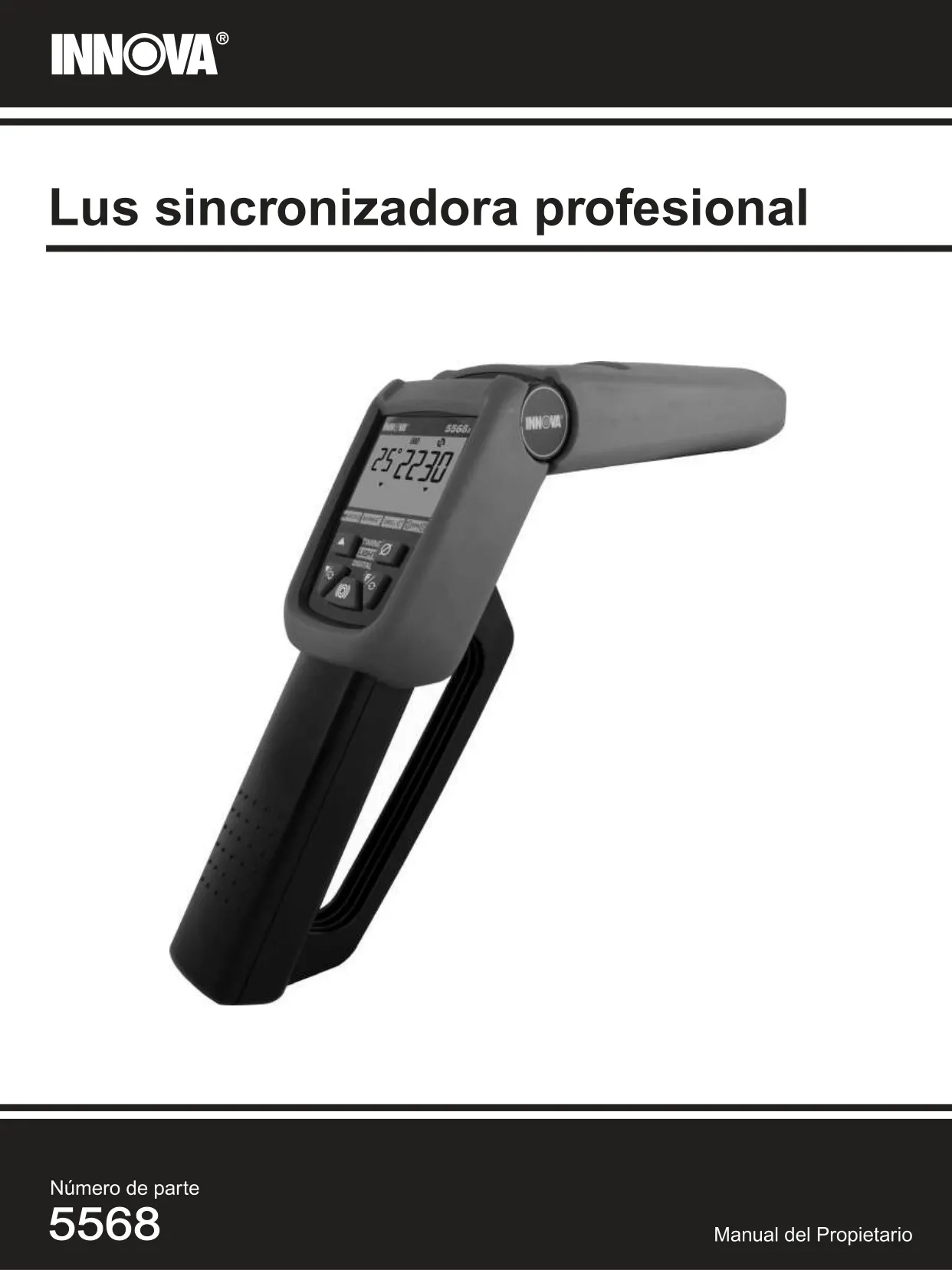
Innova 5568a Timing Light

























Innova 5568a Timing Light Instructions
Here we offer the Innova 5568a Timing Light manual completely free and in English. We have cataloged this manual in the Timing Lights section on Manualverse, and it has been rated by 1 users with an average rating of 5. If you have any specific questions about Innova 5568a Timing Light, we suggest checking the Frequently Asked Questions (FAQs) section of this manual.
Product Images

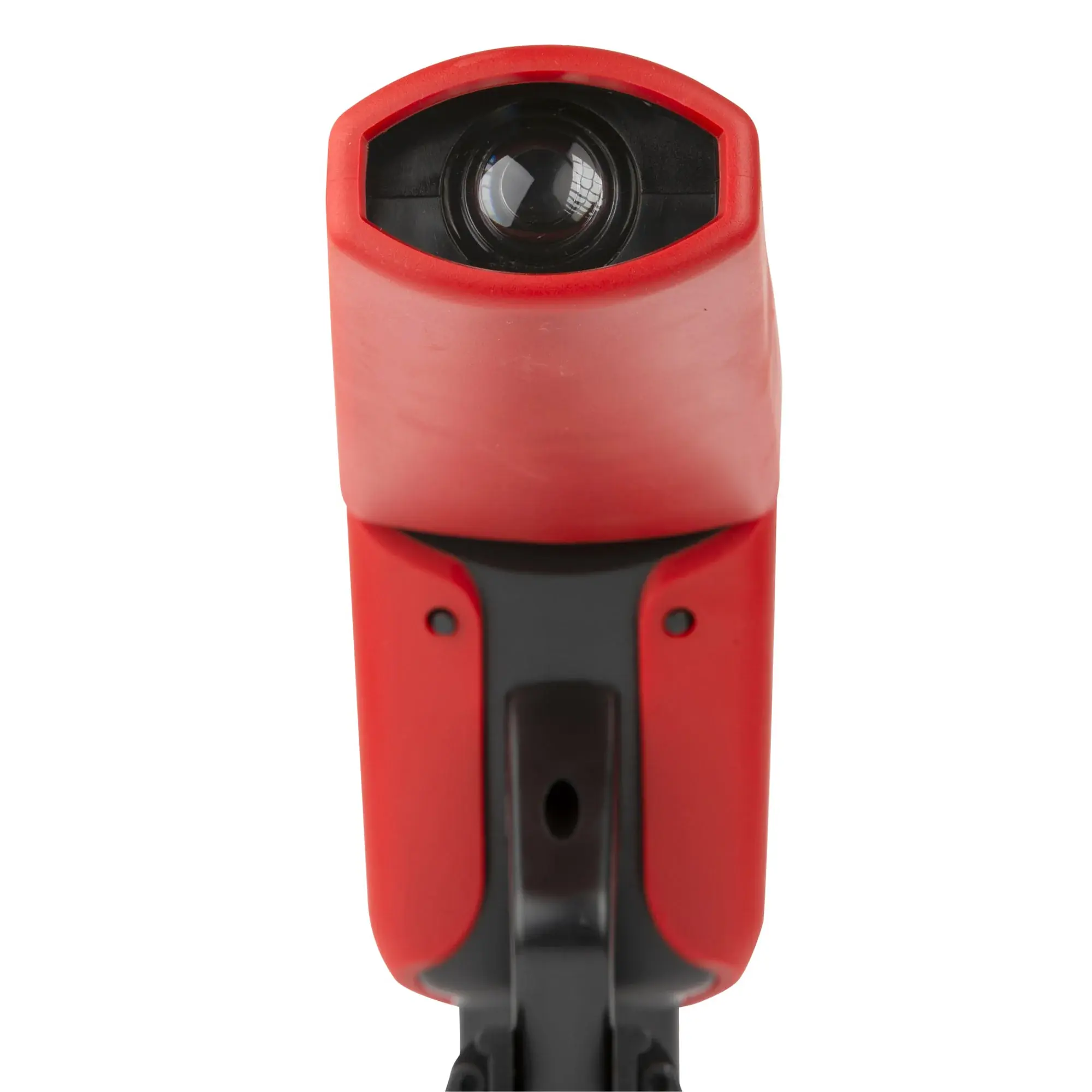
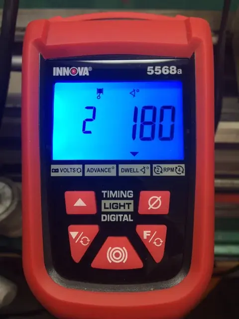
Innova 5568a Timing Light Specifications
| Feature | Specification |
|---|---|
| Product Type | Professional Digital Timing Light |
| Part Number | 5568 |
| Vehicle Compatibility | All 12-volt negative-ground vehicles |
| Supported Ignition Systems | Conventional, electronic and DIS (distributorless ignition systems) |
| Power Requirements | 10 to 16 volts DC |
| Operating Temperature | 32 to 122°F (0 to 50°C) |
| Tachometer Range | 240 to 9,990 RPM |
| Timing Advance Range | 0 to +90° |
| Light Source | Xenon bulb |
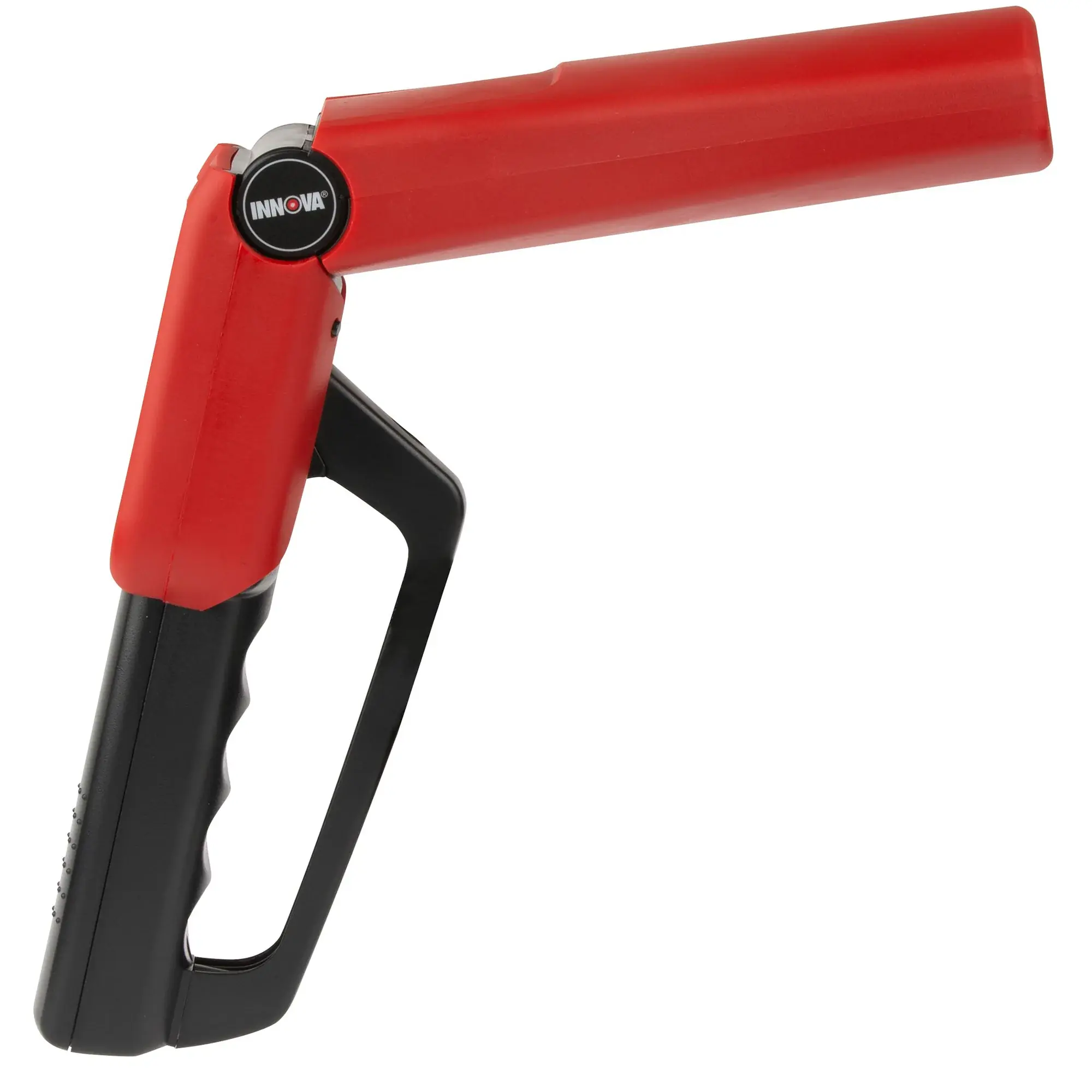
| Swiveling Head Rotation | Approximately 70° |
| Display | LCD, backlit in soft blue light |
| Displayed Parameters | Engine speed (rpm), advance (degrees), dwell angle (degrees), battery and charging system voltage |
| Operating Modes | Battery voltage, voltage/rpm, advance, dwell |
| Ignition Mode Selection | 2-cycle (DIS) or 4-cycle |
| Signal Pickup | Inductive pickup clip on No. 1 spark plug cable |
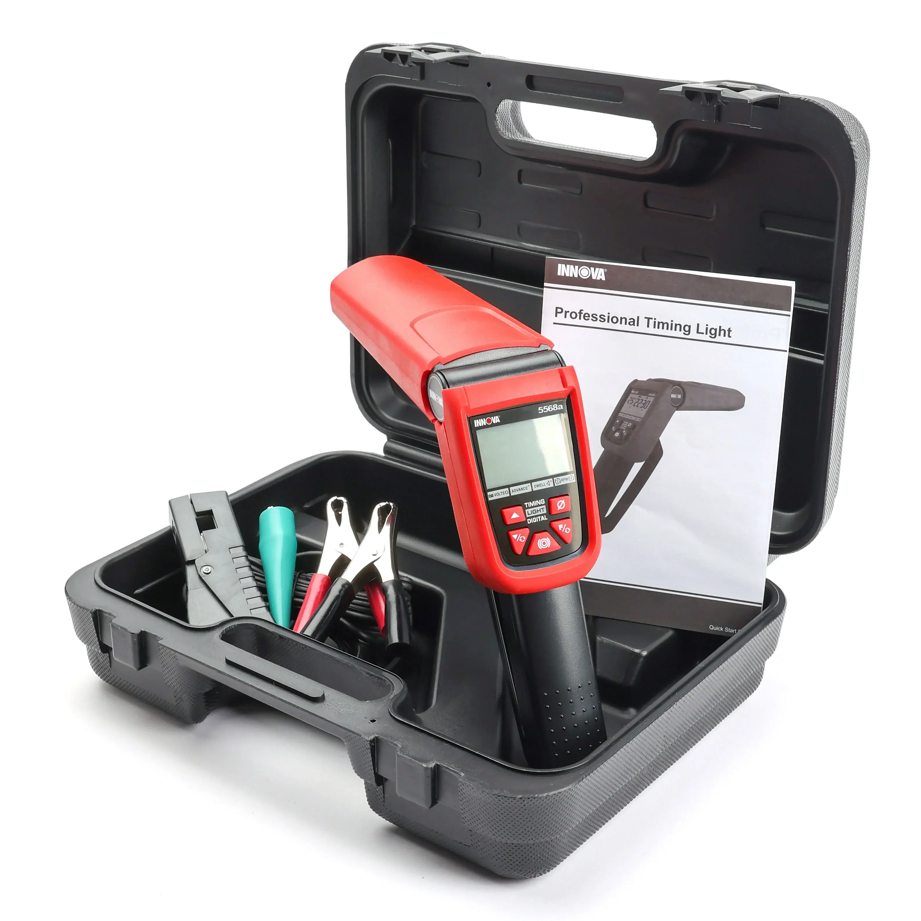
| Leads Assembly | Detachable; red battery clip, black battery clip, inductive pickup clip, green DWELL clip |
| Warranty | Limited one year, original purchaser only (non-transferable) |
| Service Turnaround | 3 to 4 weeks |
| Manual Languages | English, French, Spanish |
| Manual Reference | MRP 493-0386 |
Innova 5568a Timing Light Details
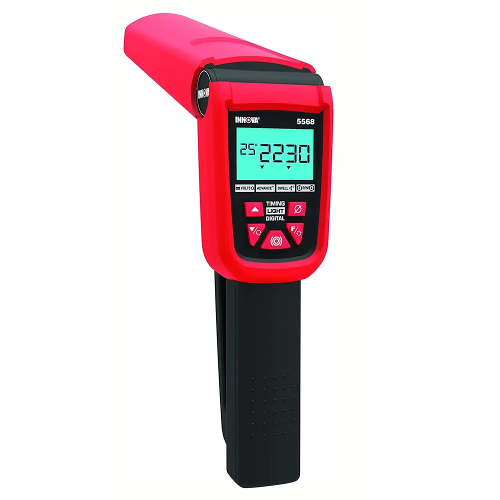
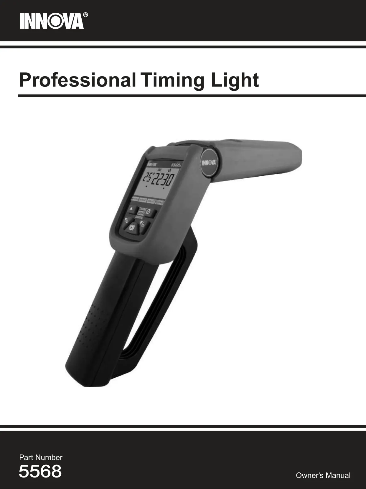
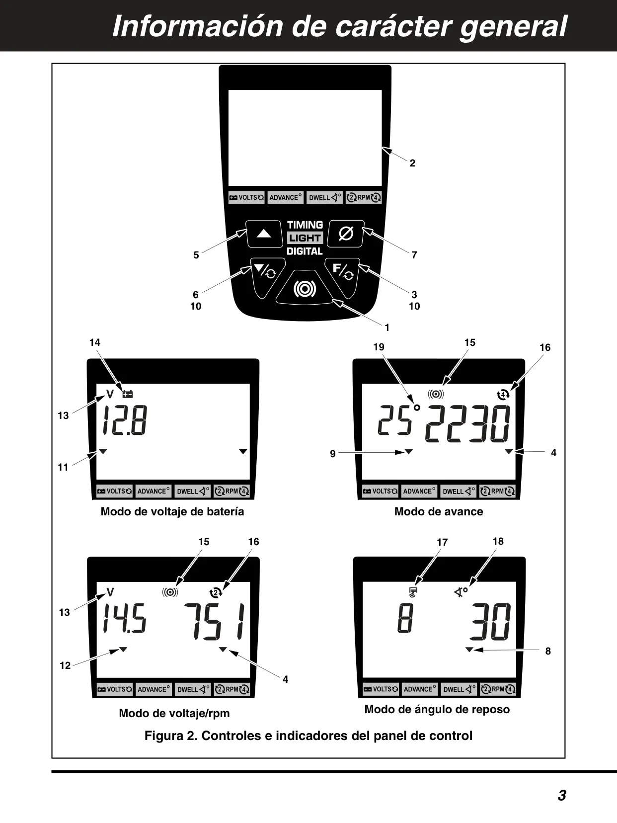
The Innova 5568a Timing Light is more than a strobe: it also works as a digital tachometer, dwell meter, advance meter and voltmeter. Its control panel has a Flash switch, a Function (F) switch, Cylinder/Advance Increment and Decrement switches, and a Zeroing switch. The Flash switch turns the strobe on and off. The Function switch steps through the voltage/rpm, advance and dwell modes. To choose 2-cycle (DIS) or 4-cycle operation, press the Function and Decrement switches at the same time.
The LCD uses a clear set of indicators and symbols. The DWELL, ADVANCE, RPM, Battery VOLTS and Charging System Battery VOLTS indicators show which mode is active. Additional symbols show volts, battery, cylinder count, dwell angle, advance degrees and the selected ignition mode. A Flash symbol blinks while the strobe is running, so you can see at a glance that the light is triggering from the ignition signal.
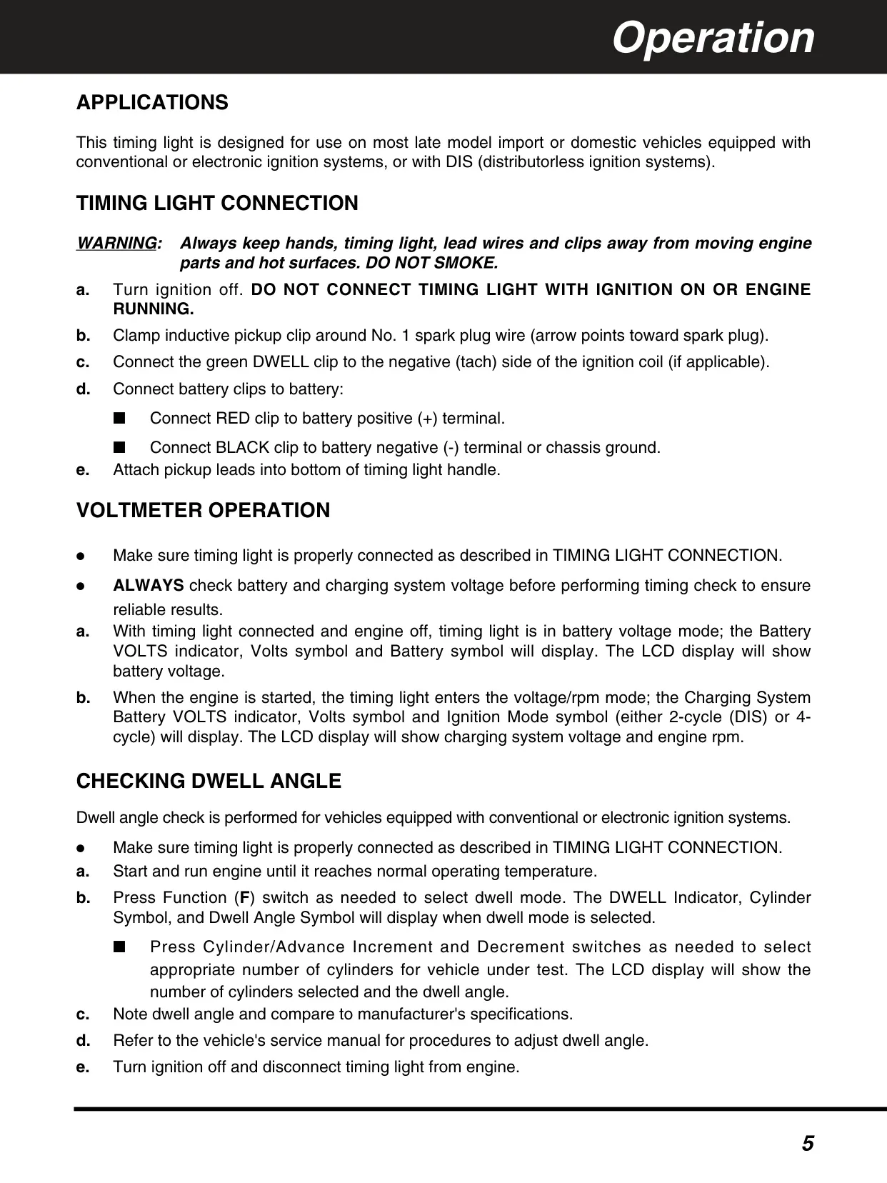
Connection is simple, but the manual gives a strict order. With the ignition off, clamp the inductive pickup around the No. 1 spark plug wire with the arrow pointing toward the plug. If applicable, attach the green DWELL clip to the negative (tach) side of the coil. Connect the red clip to battery positive and the black clip to battery negative or chassis ground. Then plug the leads into the bottom of the handle.
The voltmeter switches modes automatically. With the engine off, the unit shows battery voltage. Once the engine starts, it switches to voltage/rpm mode and shows charging system voltage together with engine speed. The manual advises you to always check battery and charging voltage before any timing test, because an unhealthy electrical system can produce unreliable results.
The dwell check applies to conventional and electronic ignition systems. After warming up the engine, select dwell mode and use the Increment/Decrement switches to set the correct number of cylinders. The display then shows dwell angle and cylinder count so you can compare them with factory specifications. On engines with distributor points, dwell should be set before initial timing is checked.
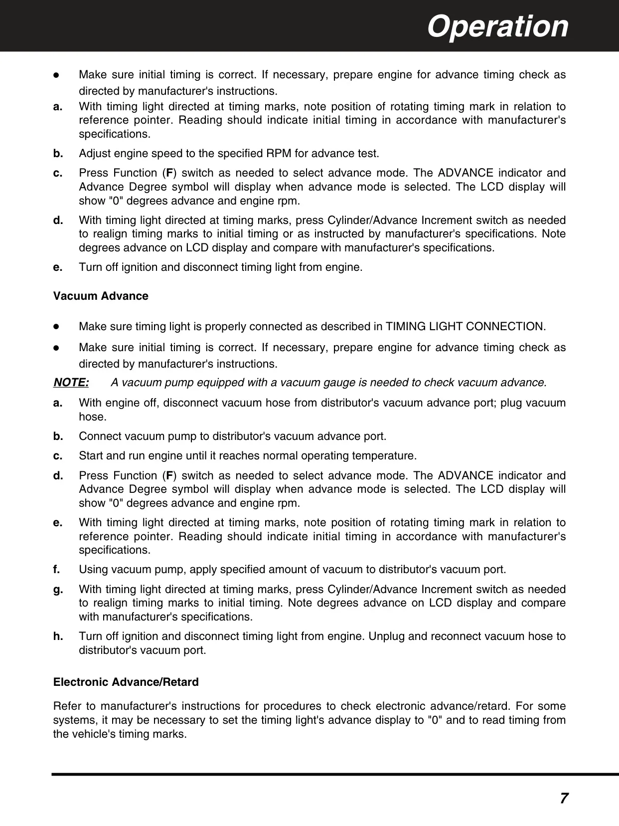
For advance testing, the unit starts at "0" degrees in advance mode. You press the Increment switch until the timing marks line up again with the initial timing position, then read the degrees of advance on the LCD. The manual describes procedures for centrifugal/mechanical advance and for vacuum advance, which needs a vacuum pump with a gauge. For electronic advance/retard systems, you may need to set the display to zero and read the timing from the engine's own marks.
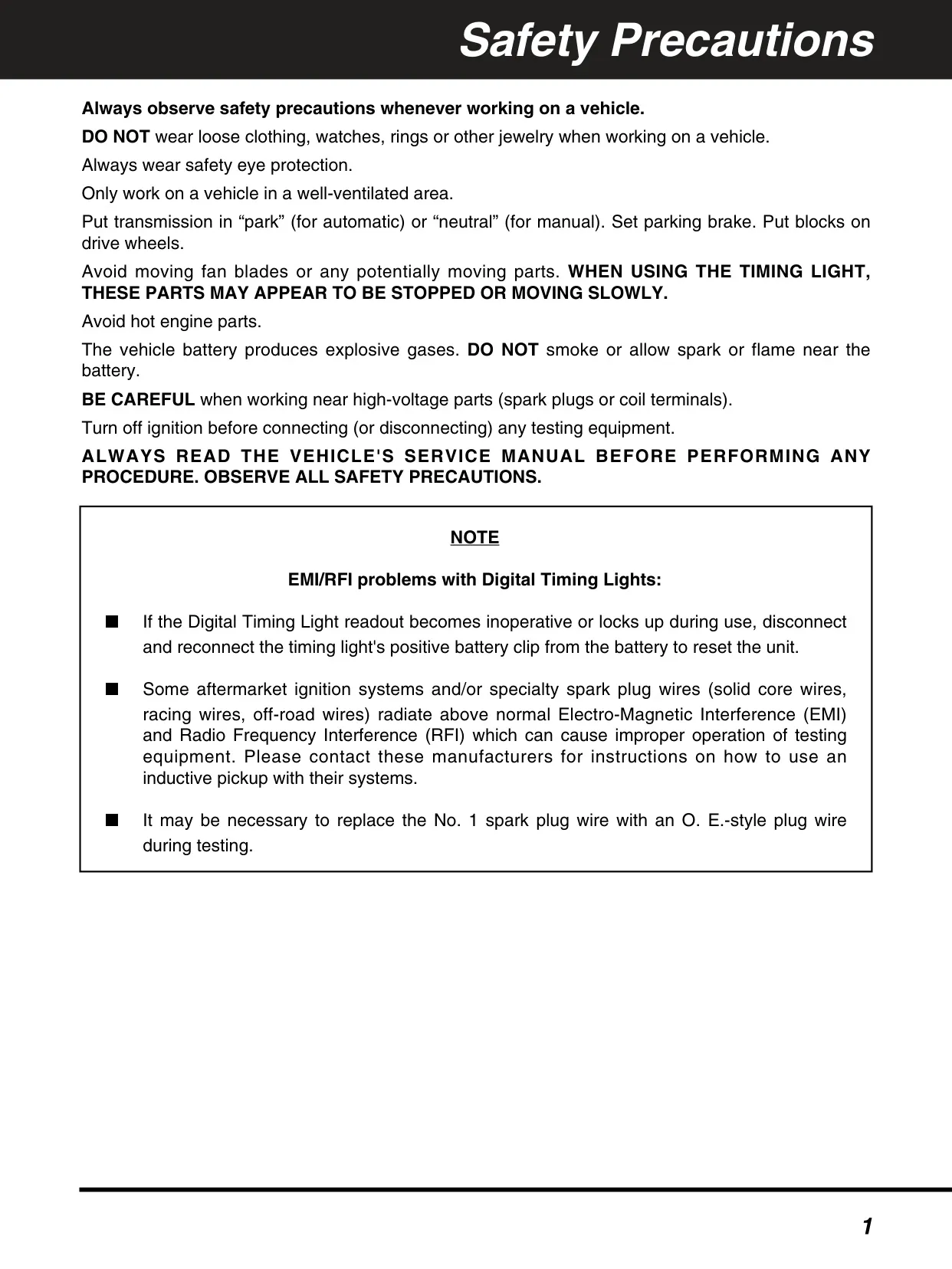
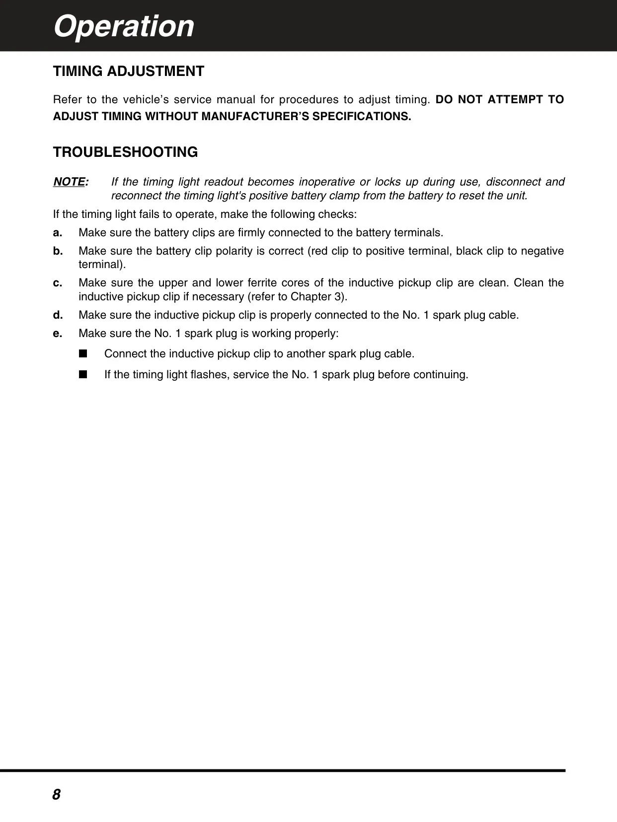
The troubleshooting section covers clip connections, polarity, clean ferrite cores and correct pickup placement. You can test the No. 1 plug circuit by moving the pickup to another wire. If the readout locks up, disconnecting and reconnecting the positive battery clip resets the unit. Aftermarket ignitions and solid-core or racing wires may cause EMI/RFI interference, so an OE-style No. 1 wire may be needed during testing.
Maintenance is minimal. To avoid erratic flashing, wipe the inside surfaces of the inductive pickup clip with a soft cloth from time to time. The detachable leads make storage easier, and replacement sets are available from dealers or the service center. The safety guidance warns that under the strobe, fans and other moving parts may appear stopped.
Frequently Asked Questions (FAQs)
Can't find the answer you need? Here are some frequently asked questions about the Innova 5568a Timing Light, and we answer them below.