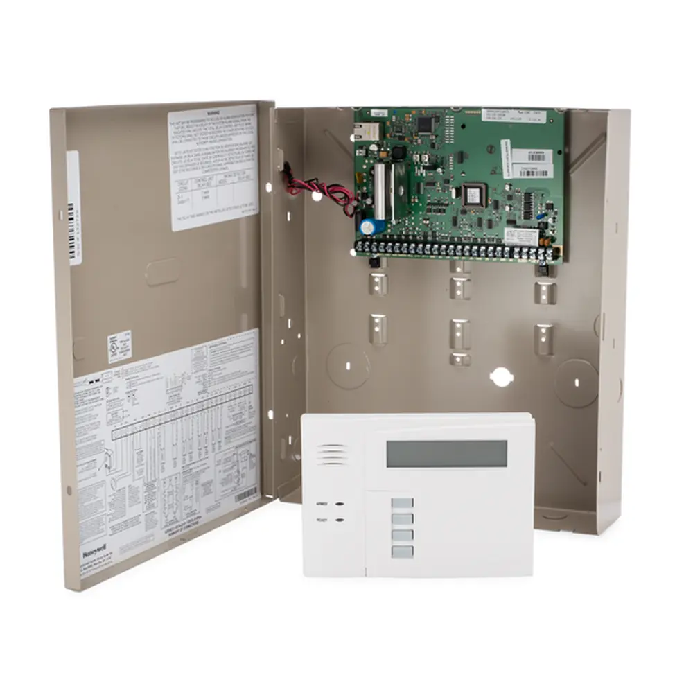
Honeywell UDC2000 Digital Controller Instruction Manual
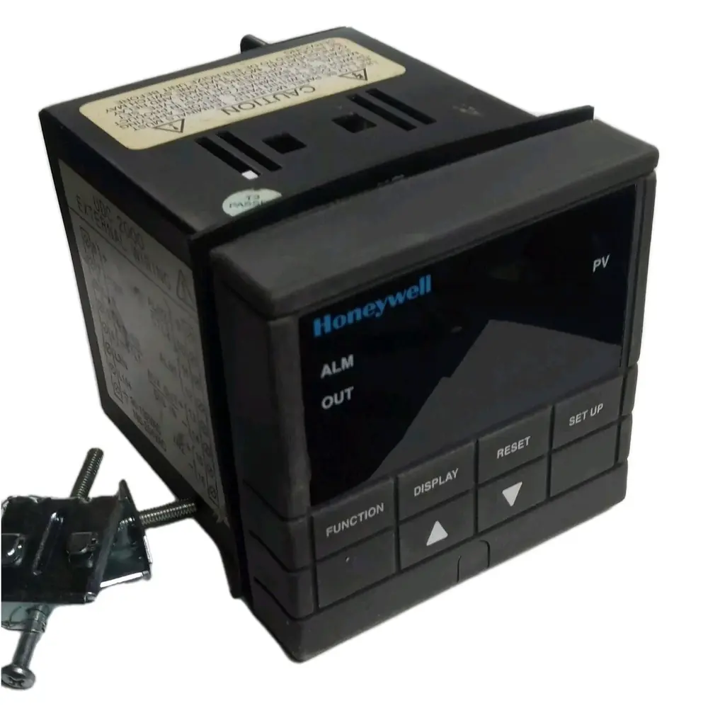
Honeywell UDC2000 Digital Controller
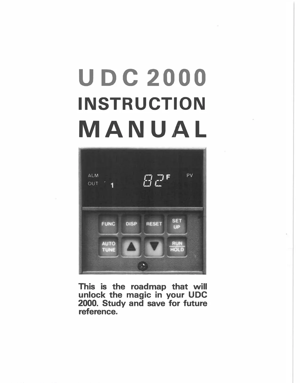
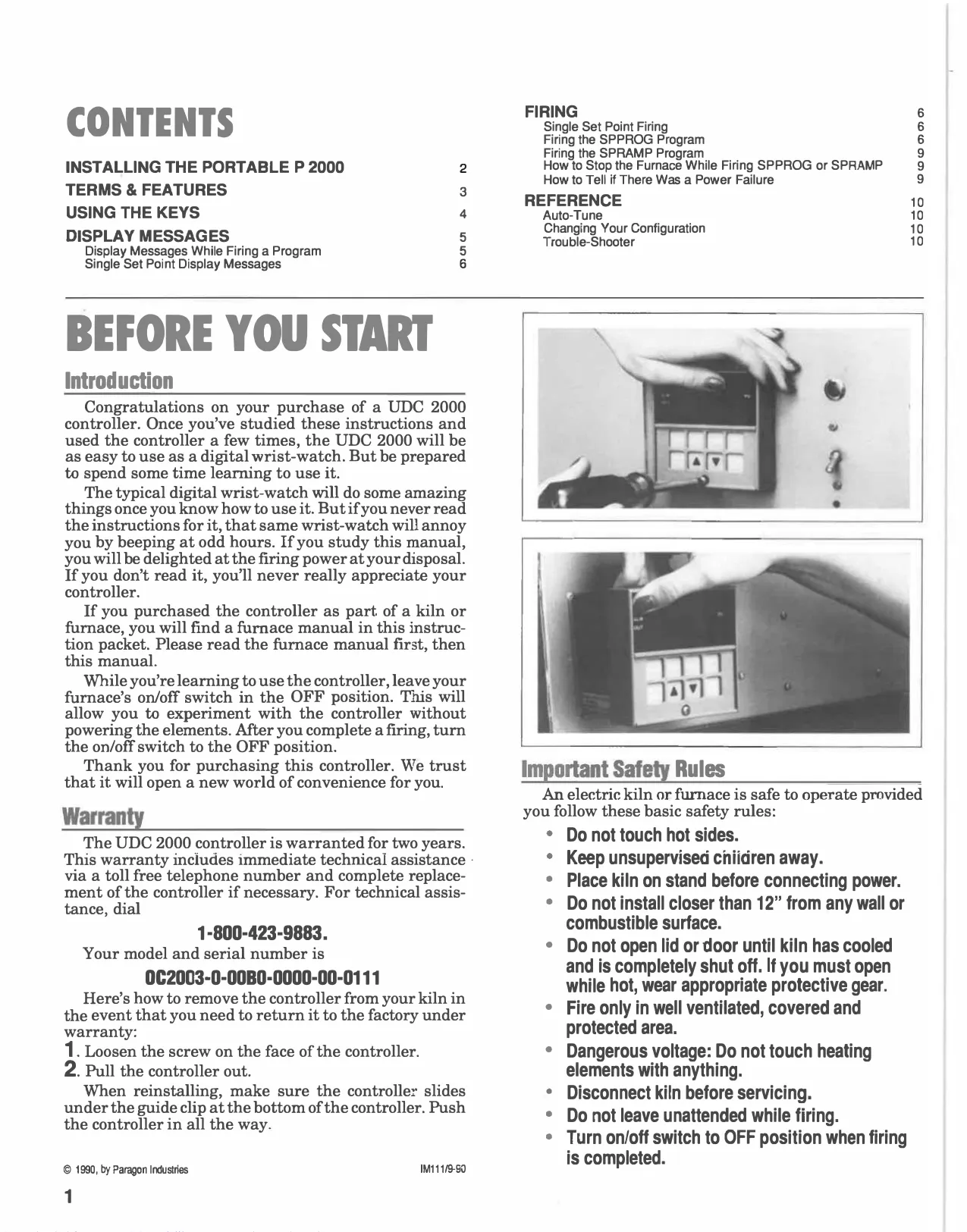
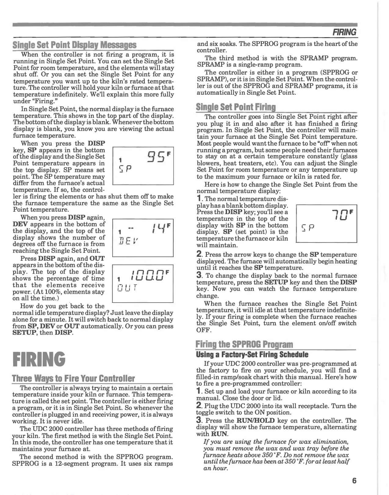
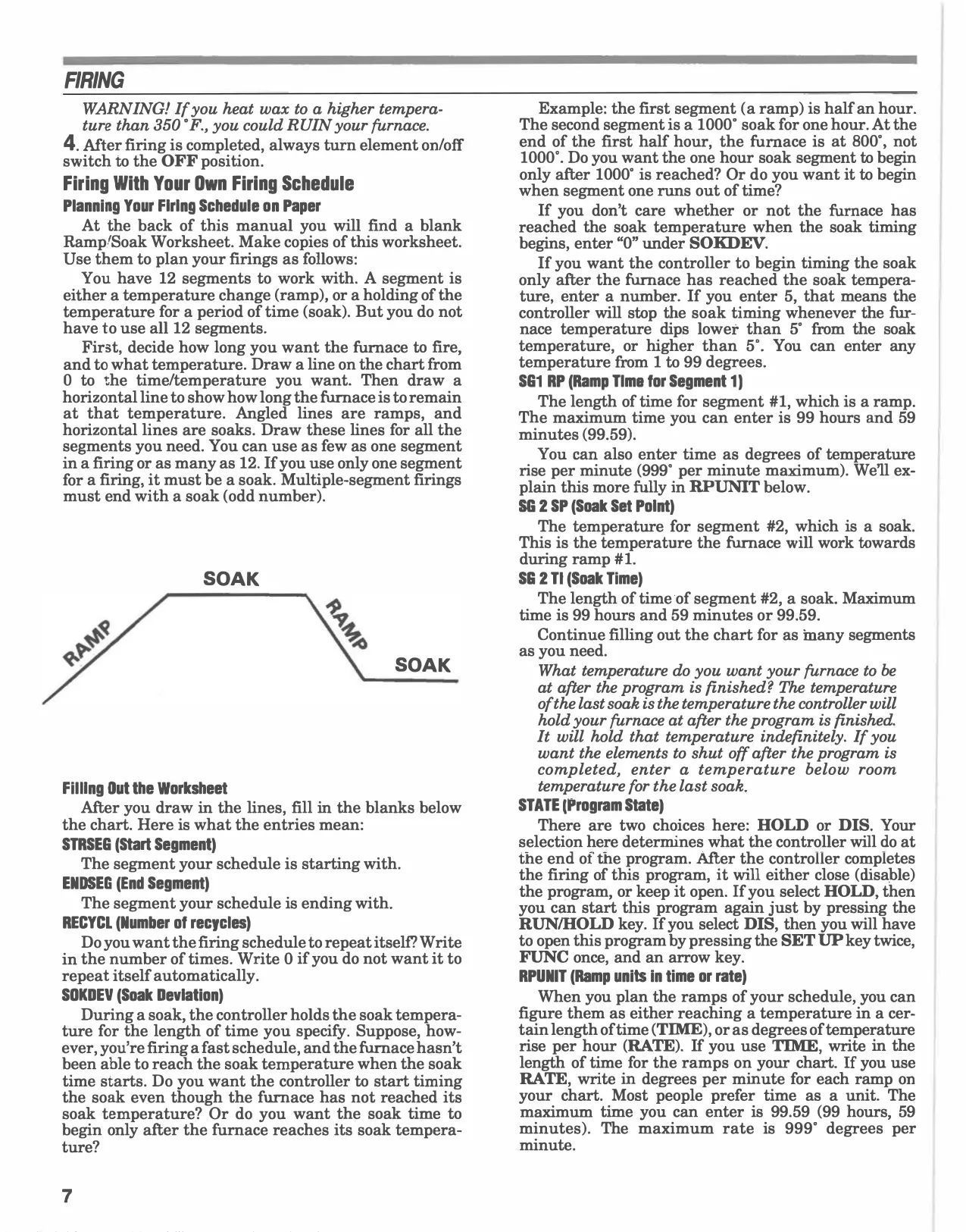

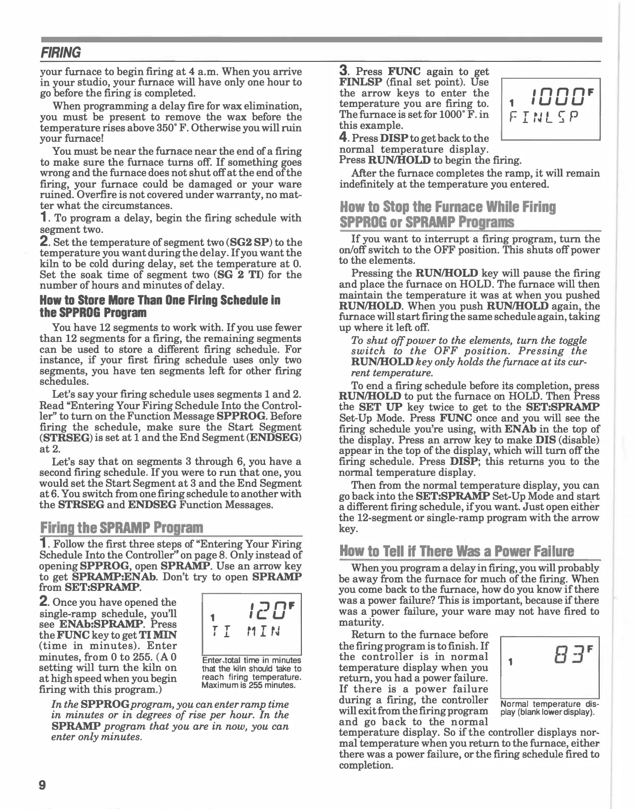
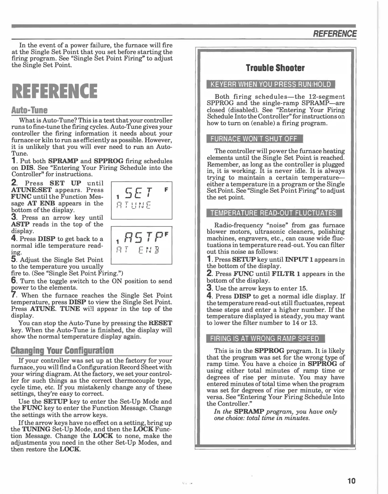


Honeywell UDC2000 Digital Controller
Honeywell UDC2000 Instructions
Here we offer the Honeywell UDC2000 Digital Controller manual completely free and in English. We have cataloged this manual in the Digital Controllers section on Manualverse, and it has been rated by 1 users with an average rating of 5. If you have any specific questions about Honeywell UDC2000 Digital Controller, we suggest checking the Frequently Asked Questions (FAQs) section of this manual.
Product Images

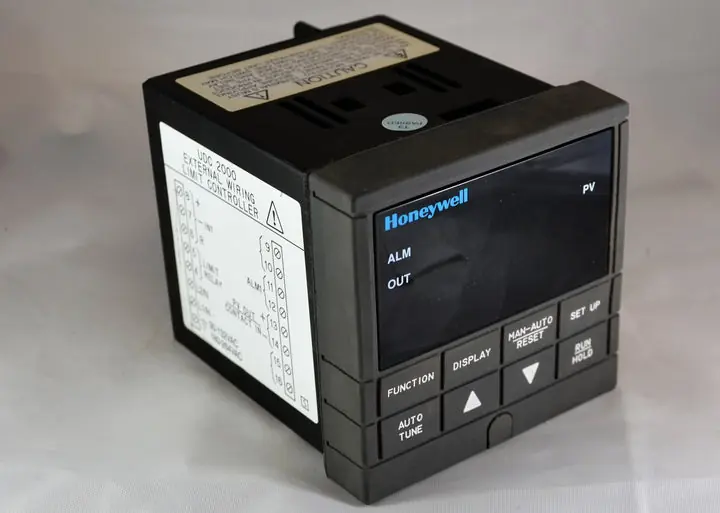
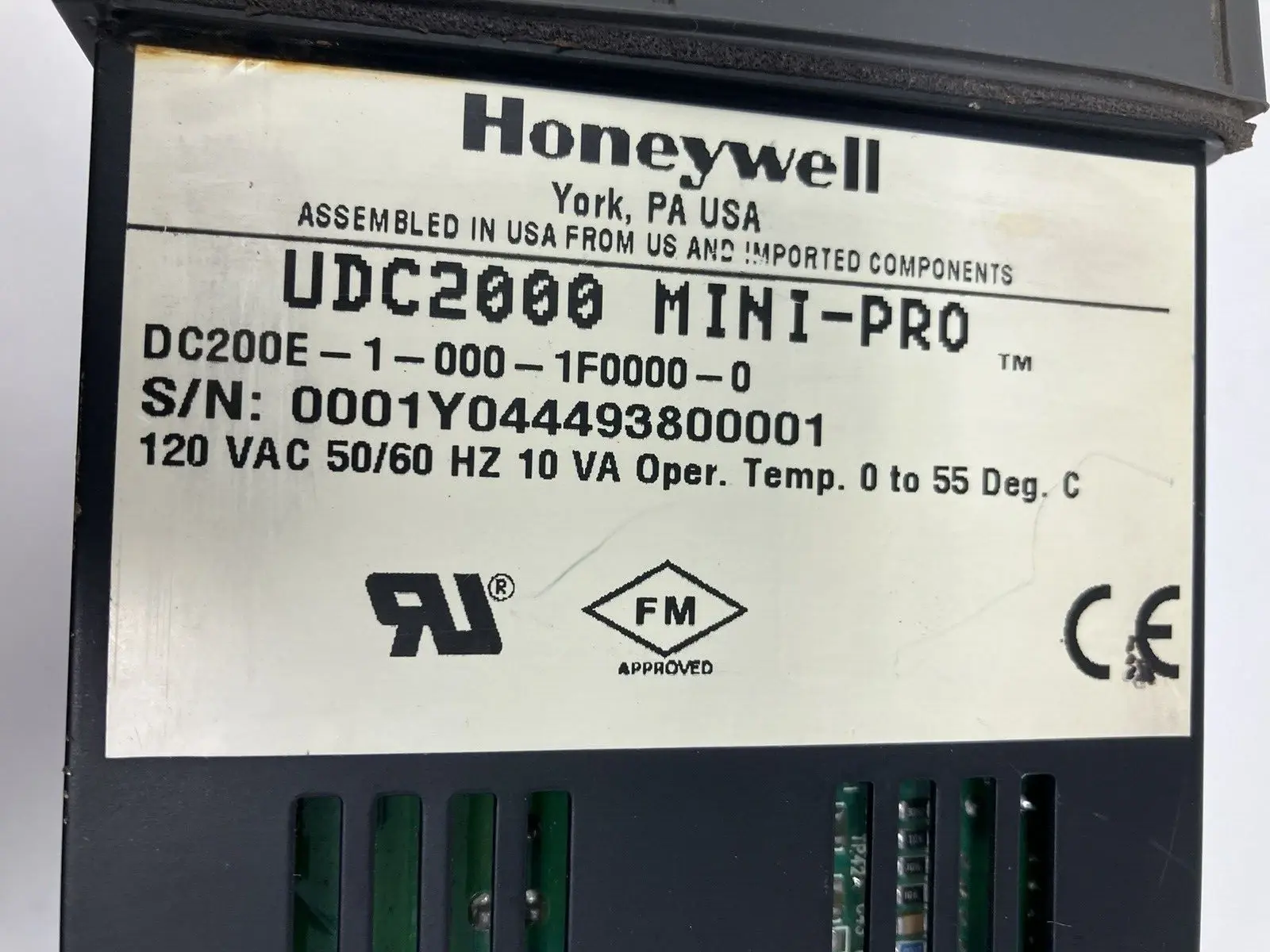
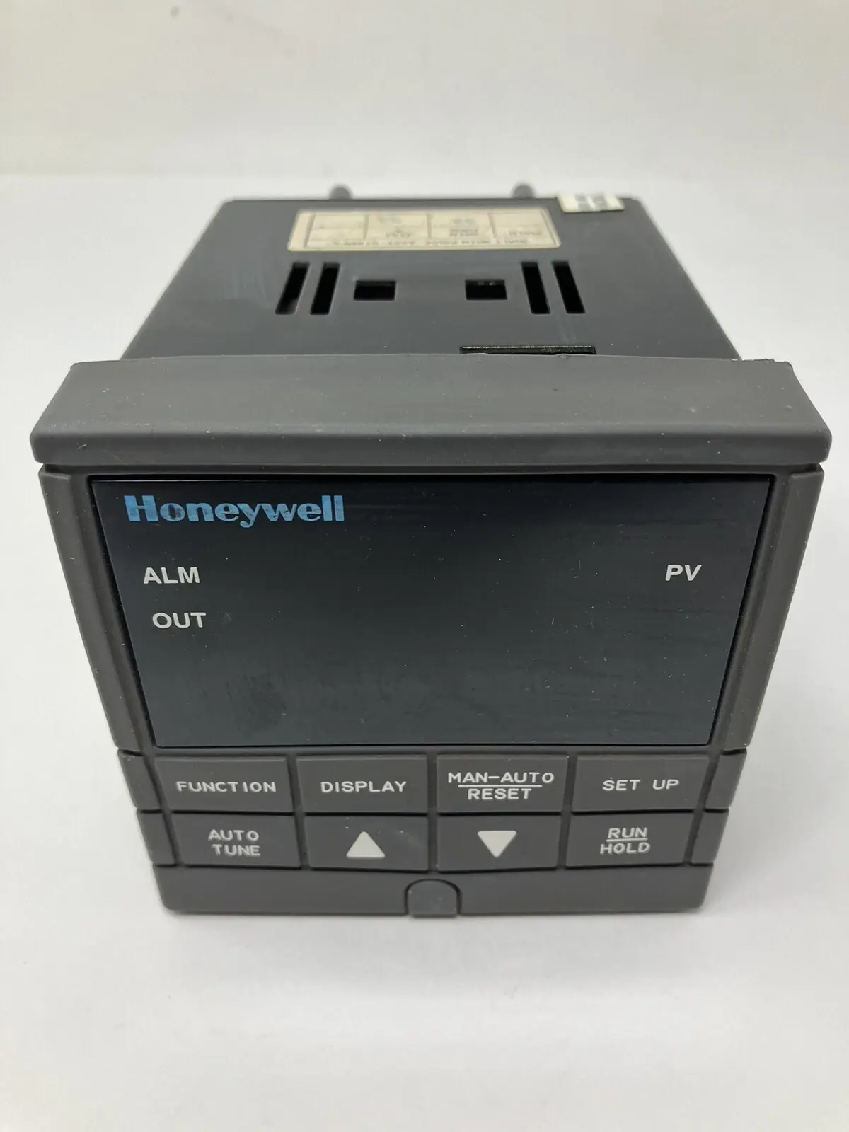
Honeywell UDC2000 Digital Controller Specifications
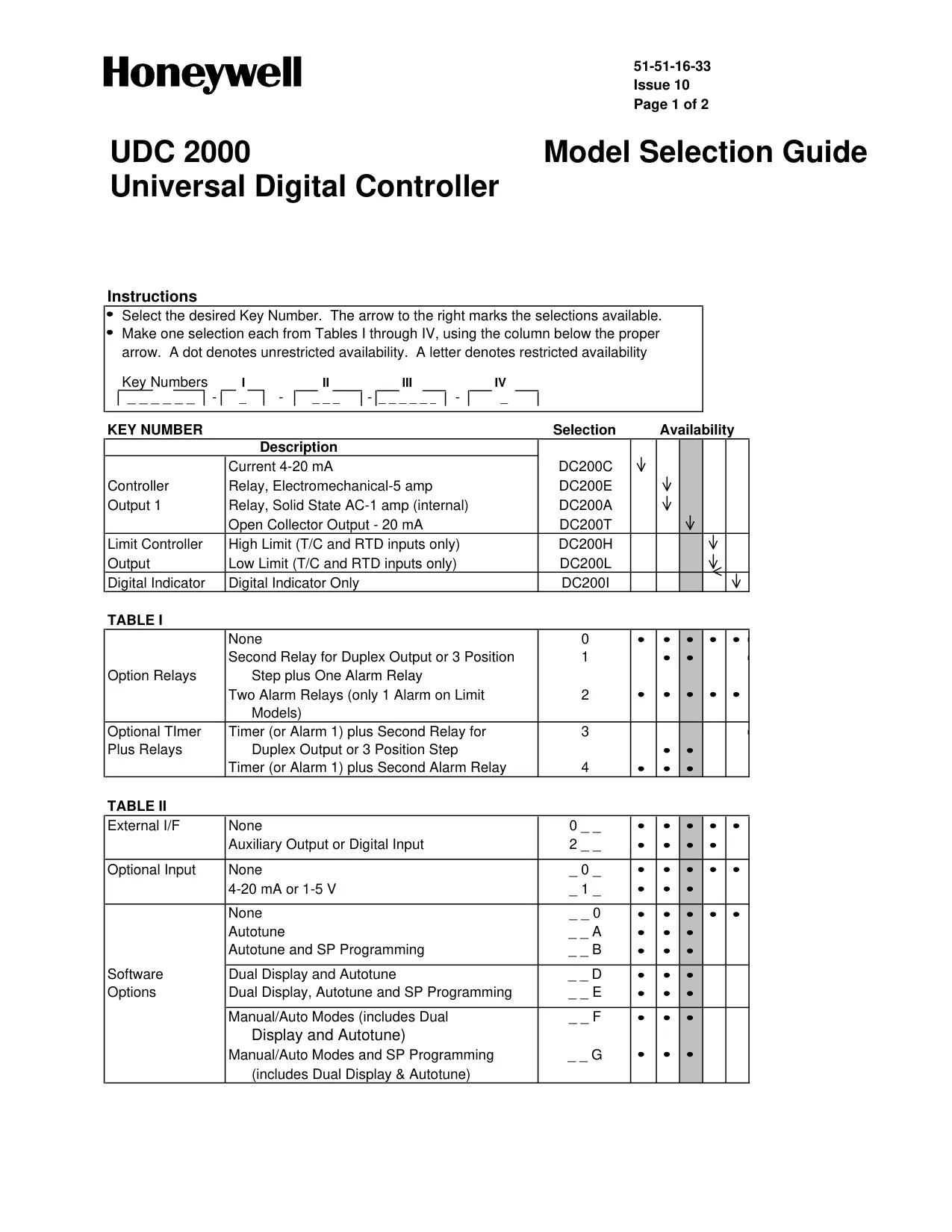
| Feature Category | Specification / Option |
|---|---|
| Controller Type (Key Number) |
DC200C: Current 4-20 mA Output DC200E: Electromechanical Relay Output - 5 amp DC200A: Solid State Relay AC Output - 1 amp (internal) DC200T: Open Collector Output - 20 mA DC200H: High Limit Controller (T/C and RTD inputs only) DC200L: Low Limit Controller (T/C and RTD inputs only) DC200I: Digital Indicator Only |
| Option Relays (Table I) |
0: None 1: Second Relay for Duplex Output or 3 Position Step + One Alarm Relay 2: Two Alarm Relays (only 1 Alarm on Limit Models) |
| Optional Timer Plus Relays (Table I) |
3: Timer (or Alarm 1) + Second Relay for Duplex Output or 3 Position Step 4: Timer (or Alarm 1) + Second Alarm Relay |
| External I/F (Table II) |
0: None 2: Auxiliary Output or Digital Input |
| Optional Input (Table II) |
0: None 1: 4-20 mA or 1-5 V |
| Software Options (Table II) |
0: None A: Autotune B: Autotune and SP Programming D: Dual Display and Autotune E: Dual Display, Autotune and SP Programming F: Manual/Auto Modes (includes Dual Display and Autotune) G: Manual/Auto Modes and SP Programming (includes Dual Display & Autotune) |
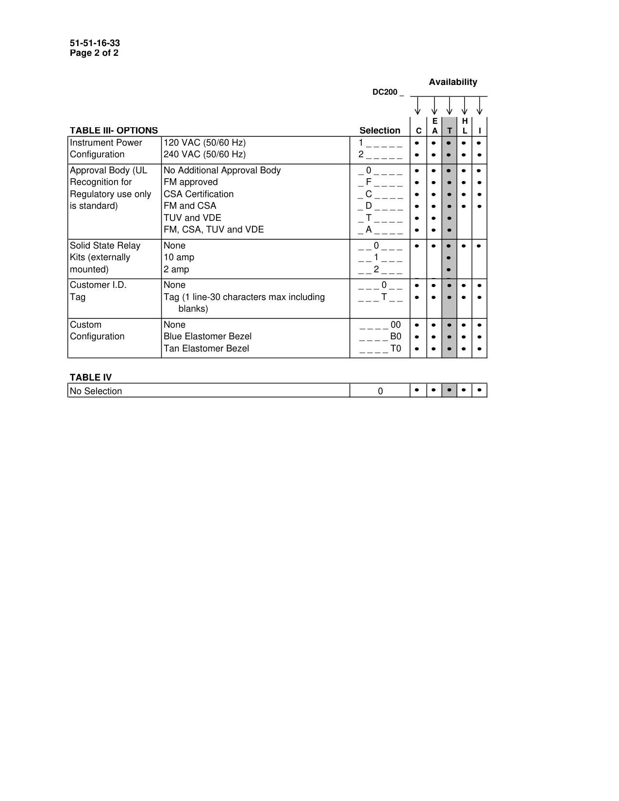
| Instrument Power Configuration (Table III) |
1: 120 VAC (50/60 Hz) 2: 240 VAC (50/60 Hz) |
| Approval Body (Table III) |
0: No Additional Approval Body (UL Recognition standard) F: FM approved C: CSA Certification D: FM and CSA T: TUV and VDE A: FM, CSA, TUV and VDE |
| Solid State Relay Kits (Table III, externally mounted) |
0: None 1: 10 amp 2: 2 amp |
| Customer I.D. Tag (Table III) |
0: None T: Tag (1 line - 30 characters max) |
| Custom Configuration (Table III) |
00: None B0: Blue Elastomer Bezel T0: Tan Elastomer Bezel |
| No Selection (Table IV) | 0: Default / No Additional Selection |
| Warranty | Two years |
| Technical Assistance | 1-800-423-9883 |
Honeywell UDC2000 Controller Details
The Honeywell UDC2000 Digital Controller is designed to offer precise control over furnace and kiln operations, making complex firing schedules manageable. While initially requiring some study, its interface aims for ease of use comparable to a digital watch, unlocking significant power and convenience for various applications. It comes with a robust two-year warranty, including immediate technical assistance.
Safety is paramount when operating equipment with the UDC2000. Users are reminded to never touch hot surfaces, keep children away, and ensure proper installation on a stand with at least 12 inches clearance from combustible materials. It's crucial not to open a hot lid without protective gear and to always fire in a well-ventilated area.
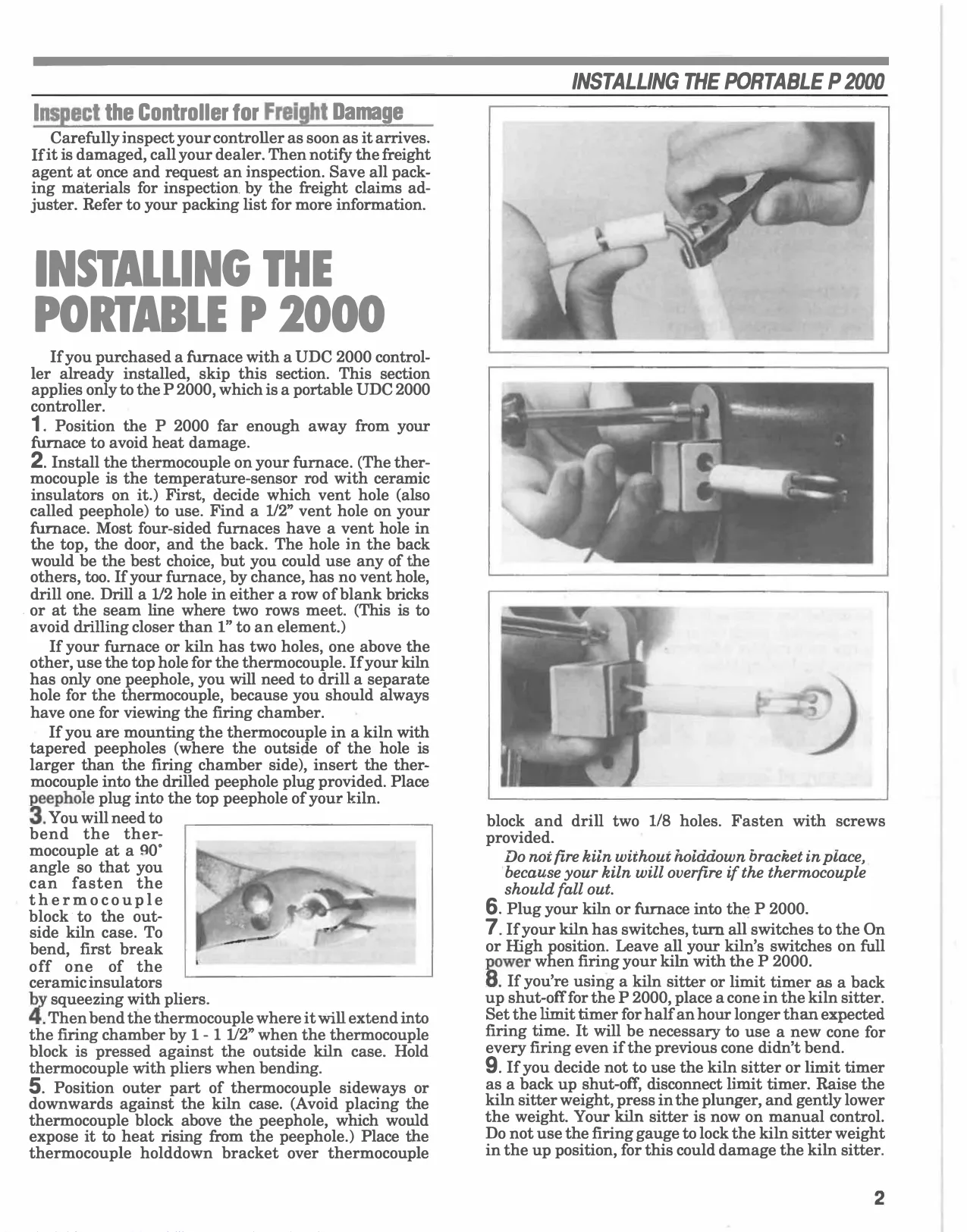
For P 2000 portable units, correct thermocouple installation is vital to prevent overfiring. This involves choosing a suitable 1/2-inch vent hole, bending the thermocouple to extend 1-1.5 inches into the chamber, and securing it with a hold-down bracket. All kiln switches should be set to ON or High when using the controller.
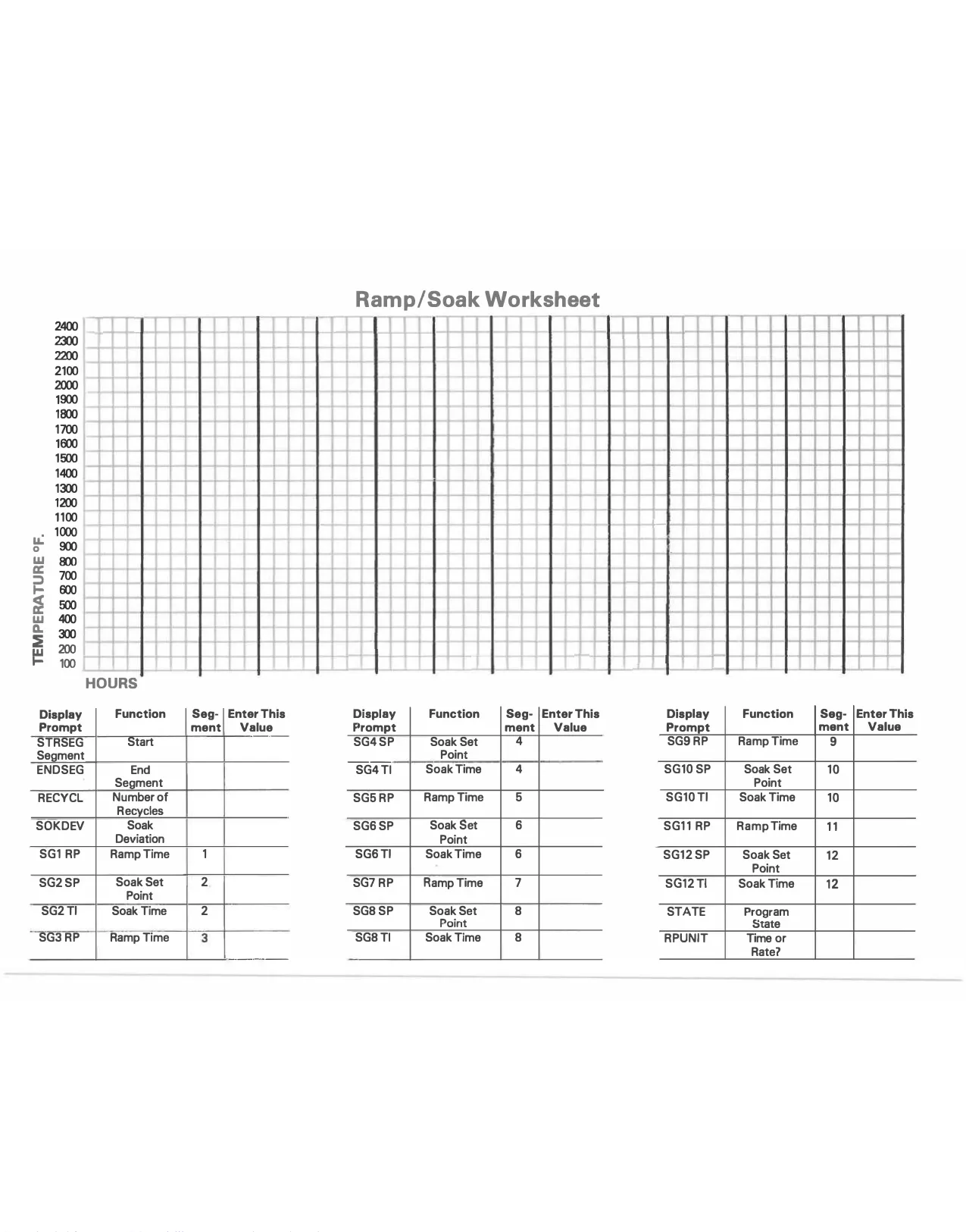
The controller utilizes distinct segments for firing: Ramps, which are stages of temperature change (increase or decrease), and Soaks, where the temperature is held steady for a specified duration. These segments form the building blocks of programmed firings.
The UDC2000 offers three primary firing methods. The Single Set Point mode maintains a constant temperature indefinitely, serving as the default when no program is active. For more complex needs, the SPRAMP program provides a single-ramp firing, allowing users to define a target temperature and the time to reach it.
The most versatile method is the SPPROG, a 12-segment program incorporating six ramps and six soaks. This method allows for intricate, multi-stage firing schedules, which can be either factory-preset or entirely user-defined. This flexibility makes it suitable for diverse industrial and artistic applications.
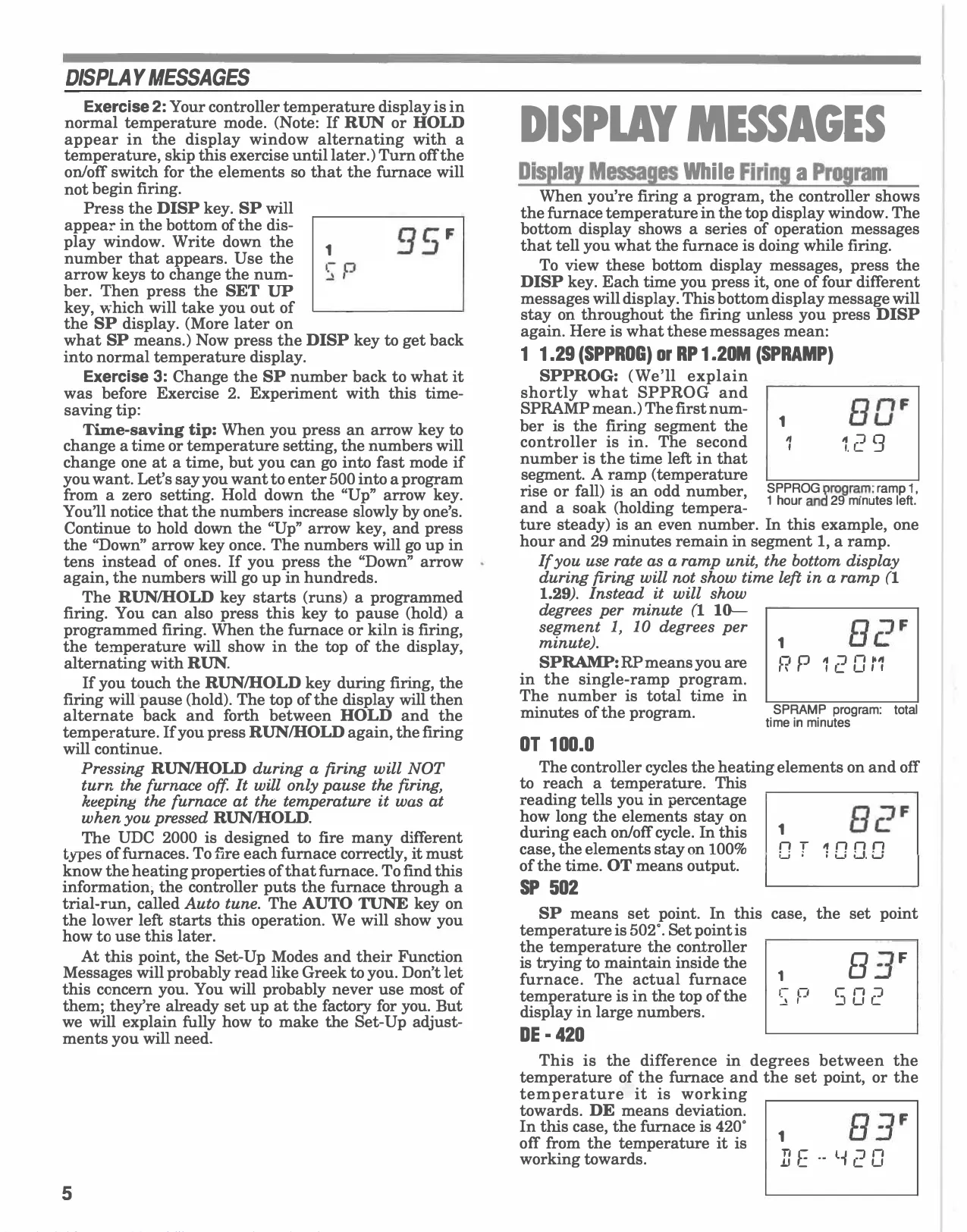
Understanding the display messages is key. During firing, the lower display cycles through operational messages like the current segment and time left (e.g., 1 1.29 for SPPROG), total program time (RP 1.20M for SPRAMP), heating element output percentage (OT 100.0), the active set point (SP 502), and temperature deviation (DE-420).
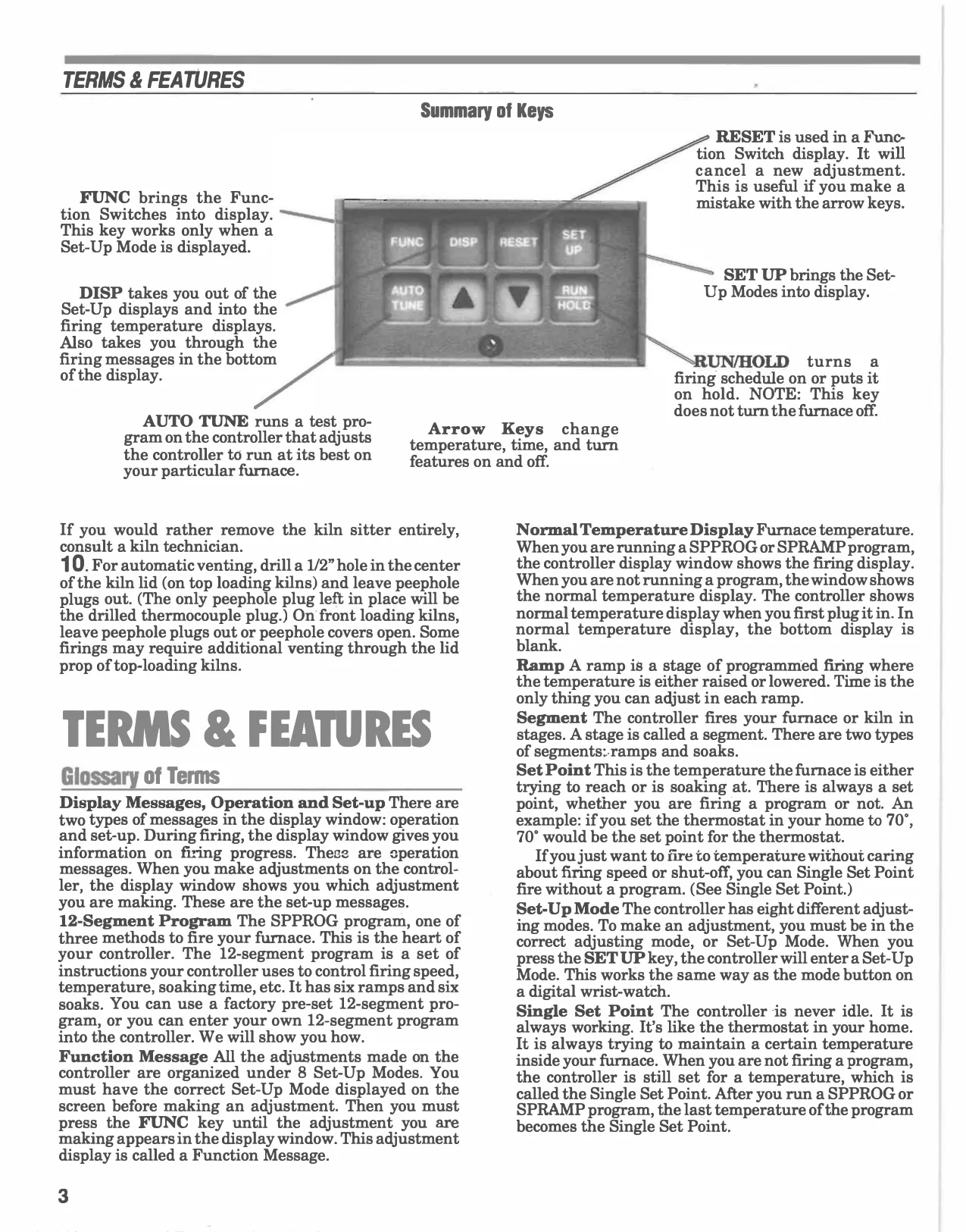
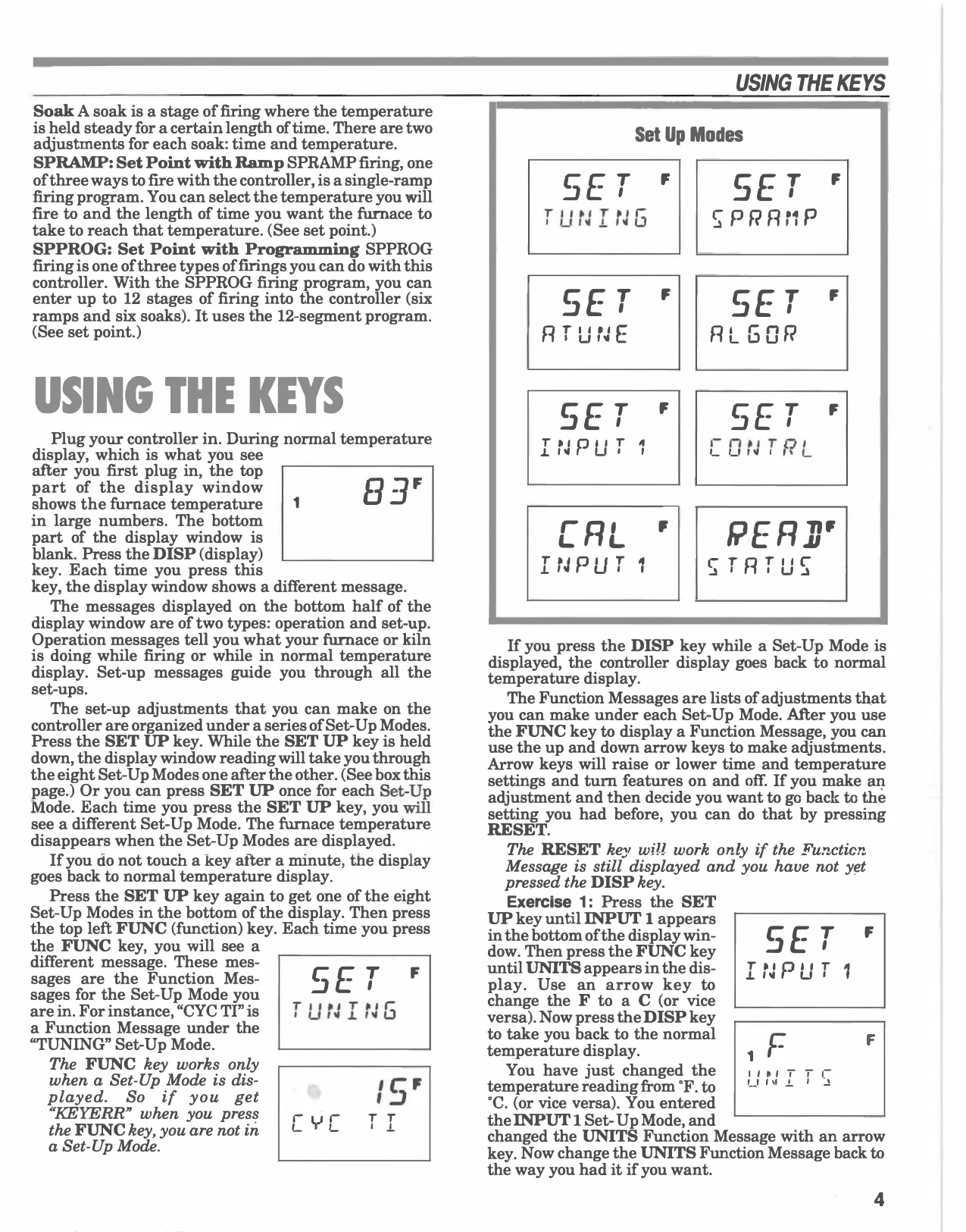
Key operation involves SET UP for accessing adjusting modes, FUNC for function messages within those modes, and arrow keys for value changes. The DISP key cycles through operational messages and exits set-up displays. RUN/HOLD starts or pauses a program, but critically, it *does not* turn off the furnace; only the main on/off switch does.
The AUTO TUNE feature is a self-optimization process where the controller runs a trial to learn the furnace's heating properties, though it's rarely needed for factory-calibrated units. A RESET key allows users to cancel adjustments made with arrow keys before exiting a function message.
Specialized programming includes Delay Fire, which schedules a program to begin at a later time. This requires careful attention, especially for processes like wax elimination, where wax must be removed before temperatures exceed 350°F to prevent furnace damage. Users must always be present at the end of firing.
The controller also supports storing multiple firing schedules within the SPPROG program by utilizing different segment ranges. If a power failure occurs, the controller will automatically exit any active firing program and revert to the normal temperature display, running at the previously set Single Set Point.
Troubleshooting guidance addresses common issues. A KEYERR when pressing RUN/HOLD indicates that both SPRAMP and SPPROG firing schedules are disabled. Fluctuating temperature readings, often caused by radio-frequency noise, can be resolved by adjusting the FILTH 1 setting in the INPUT 1 Set-Up Mode.
Frequently Asked Questions (FAQs)
Can't find the answer you need? Here are some frequently asked questions about the Honeywell UDC2000 Digital Controller, and we answer them below.