Trane TR150 Variable Frequency Drive Instruction Manual
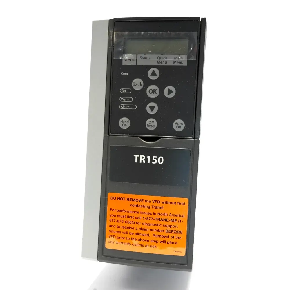
Trane TR150 Variable Frequency Drive
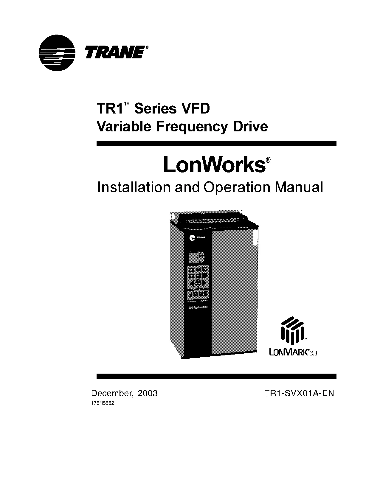
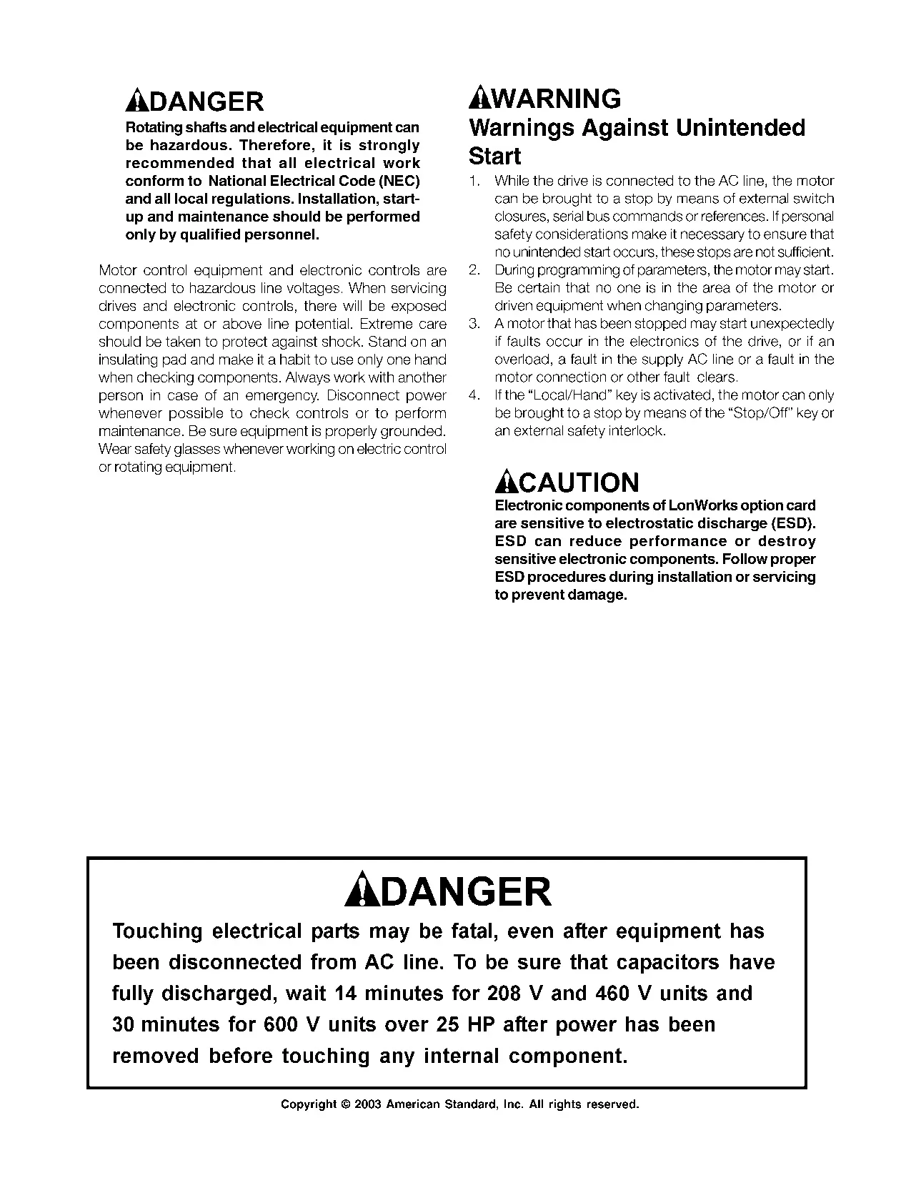
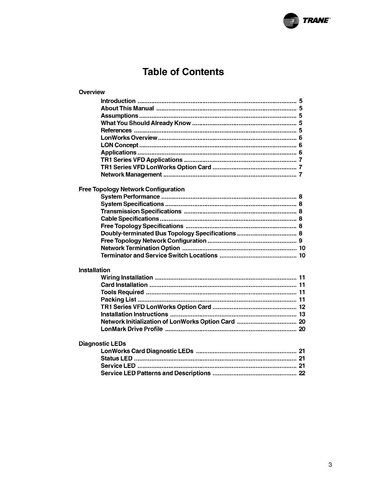




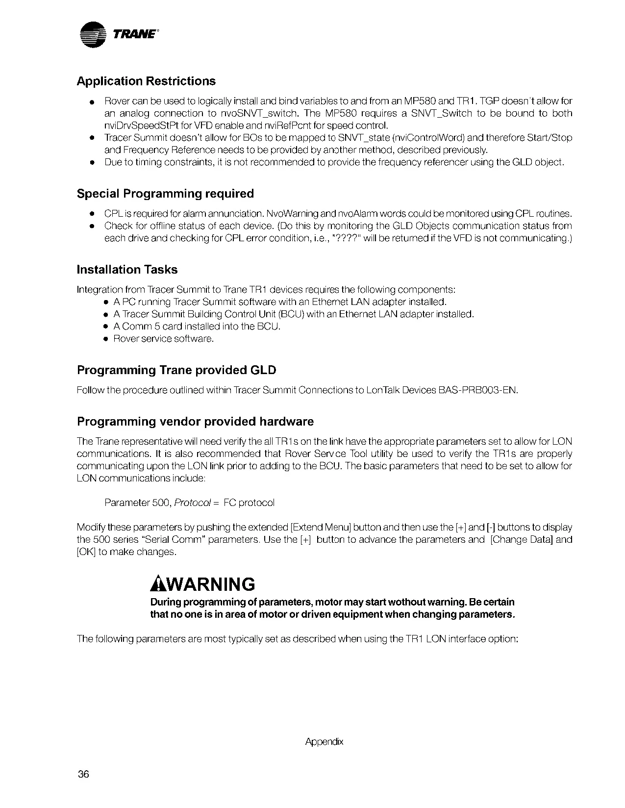
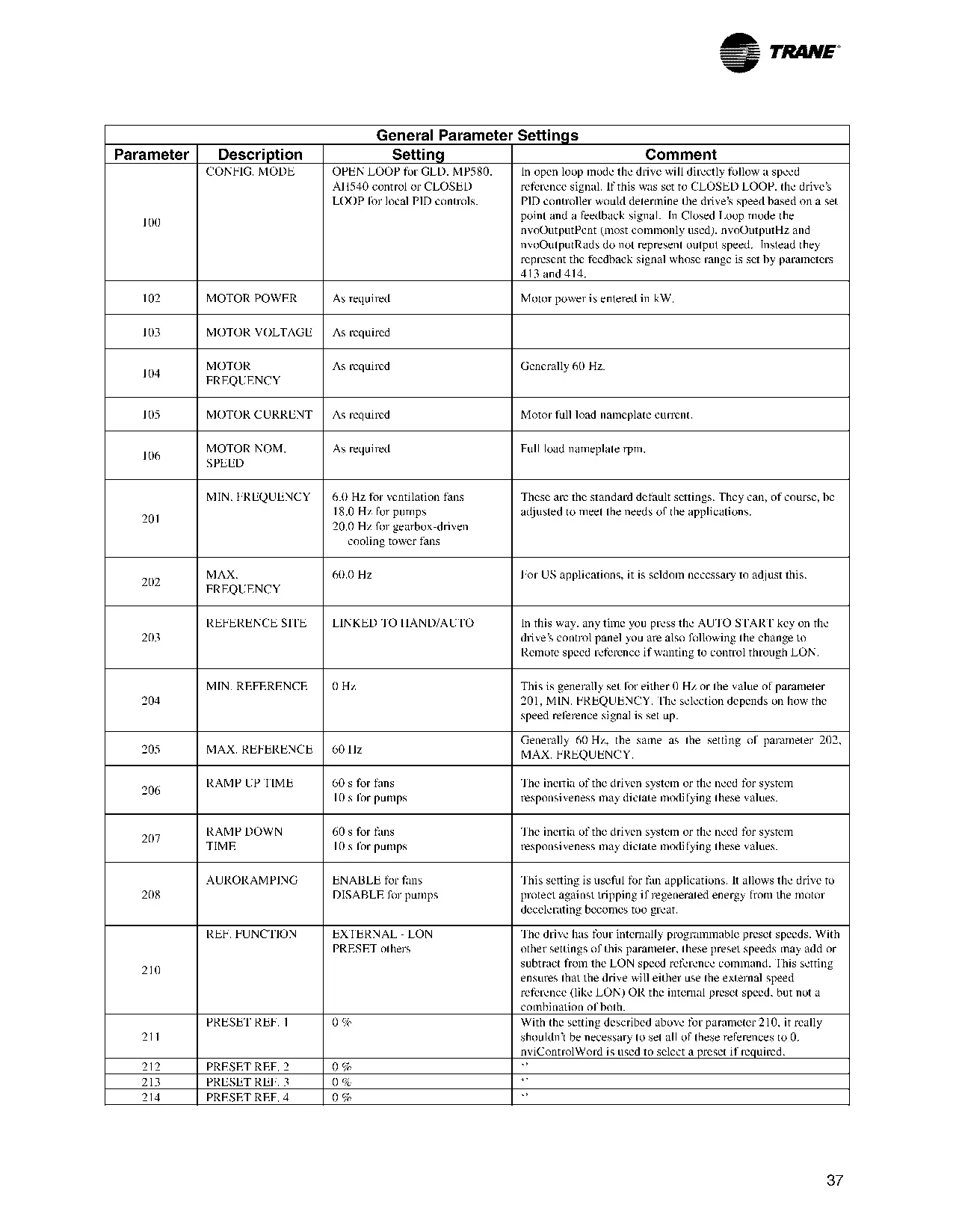

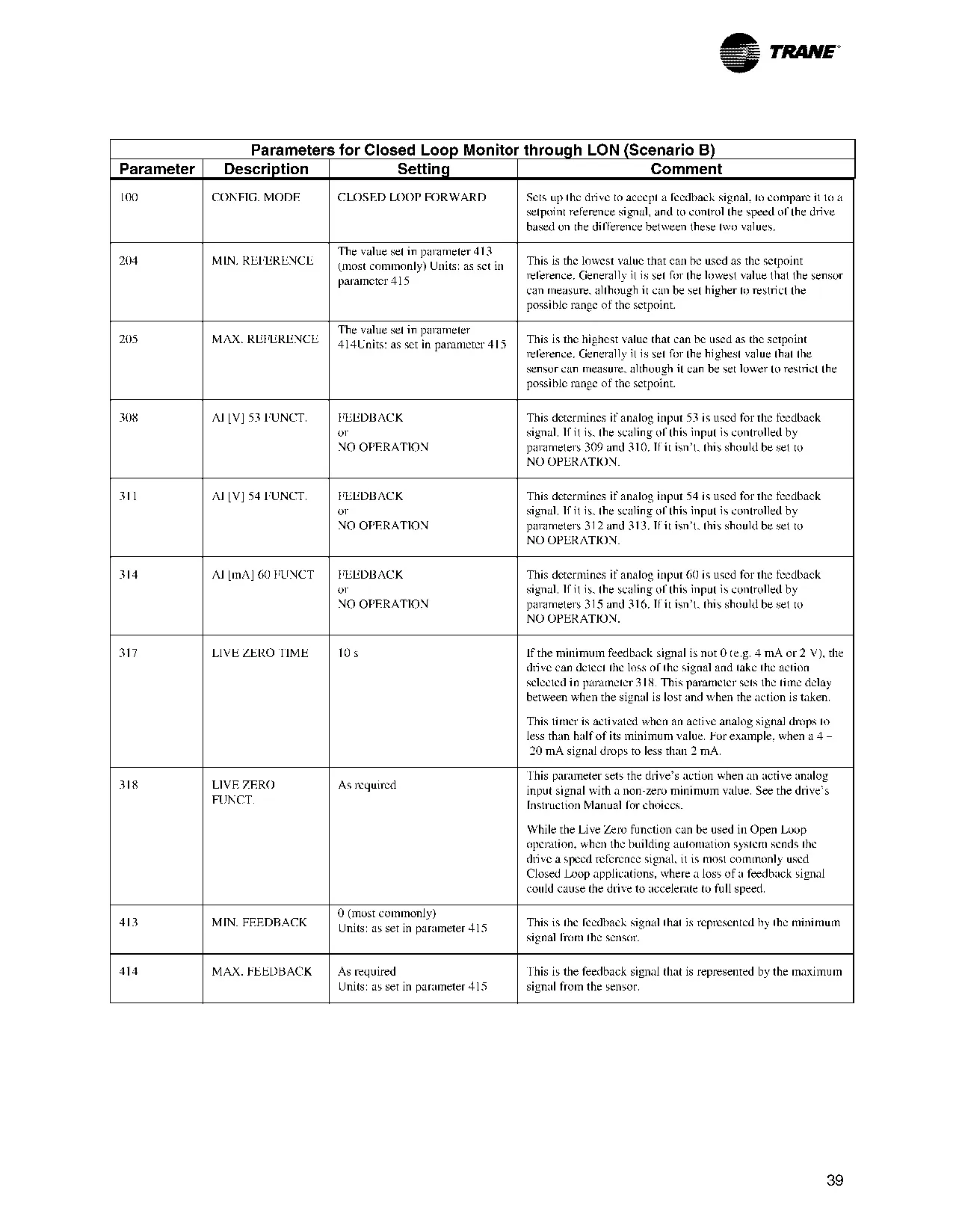
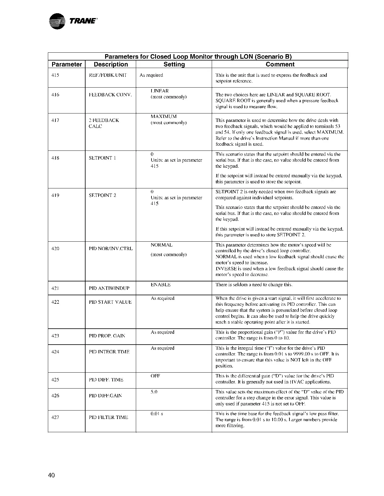
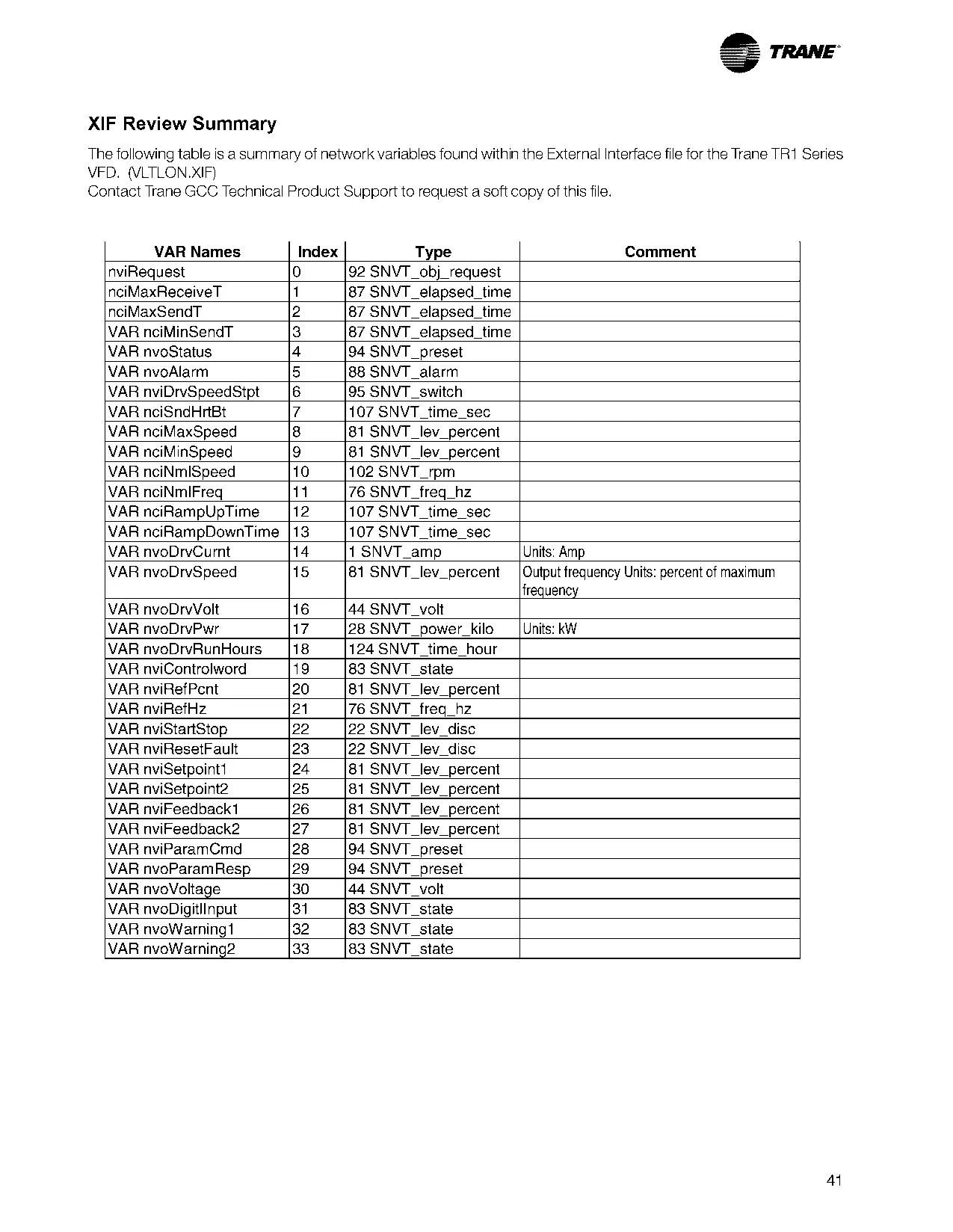
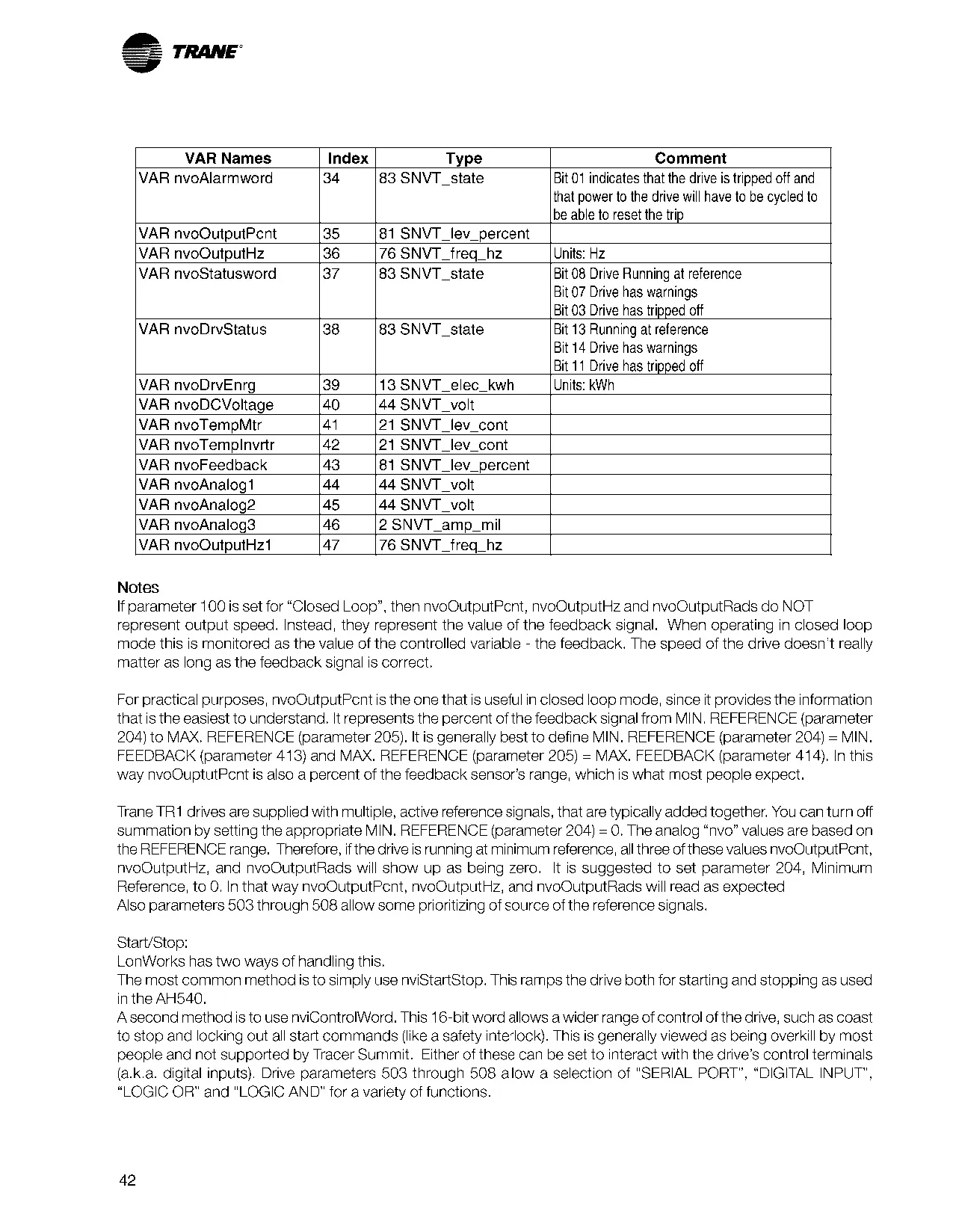
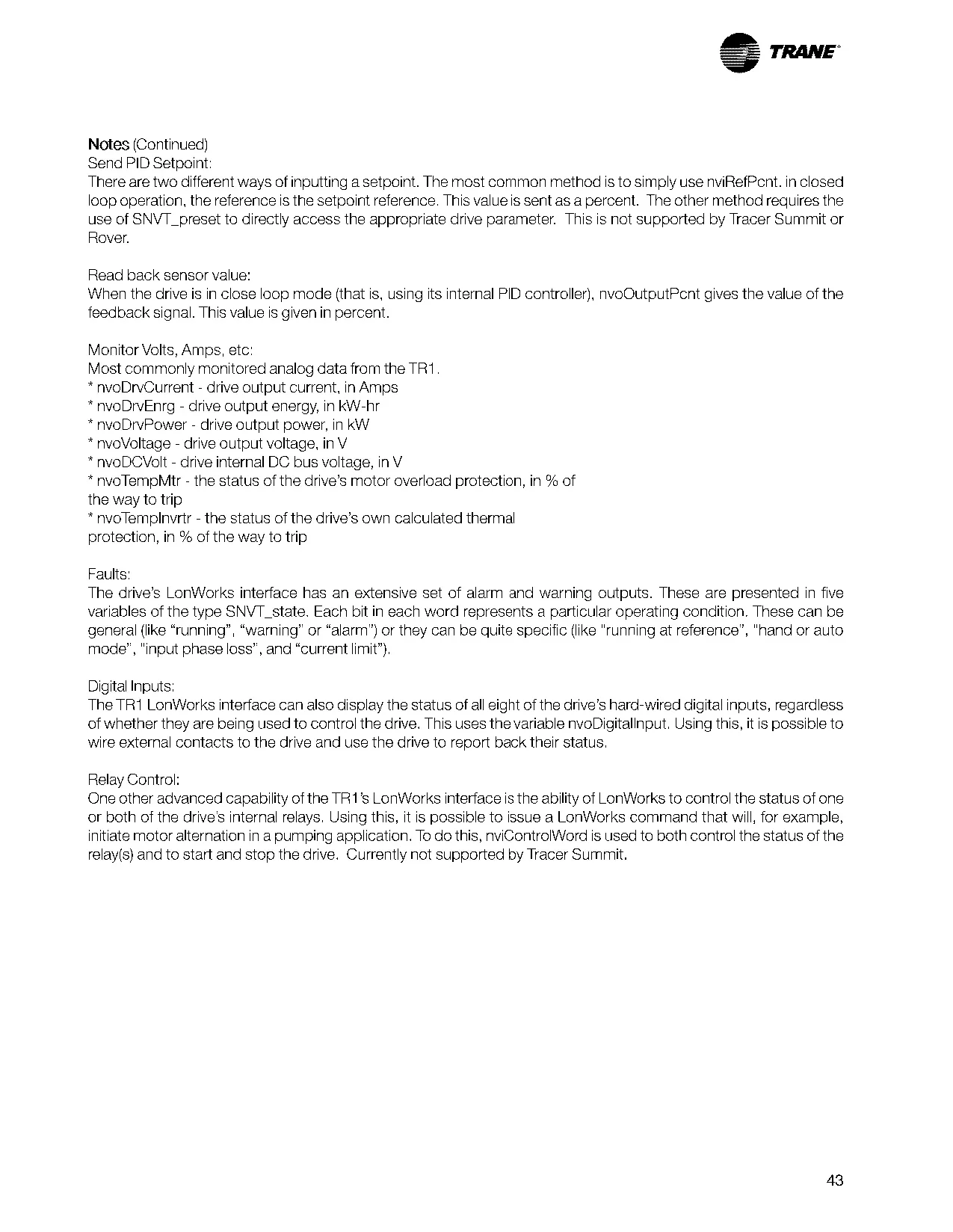


Trane TR150 Variable Frequency Drive
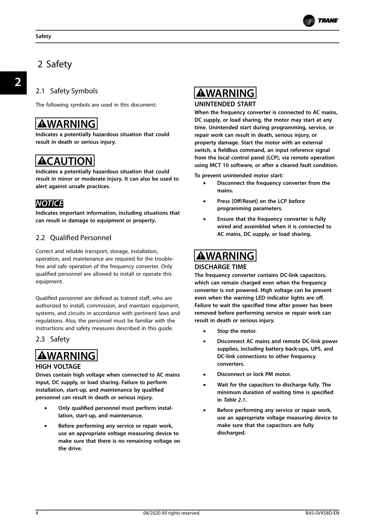
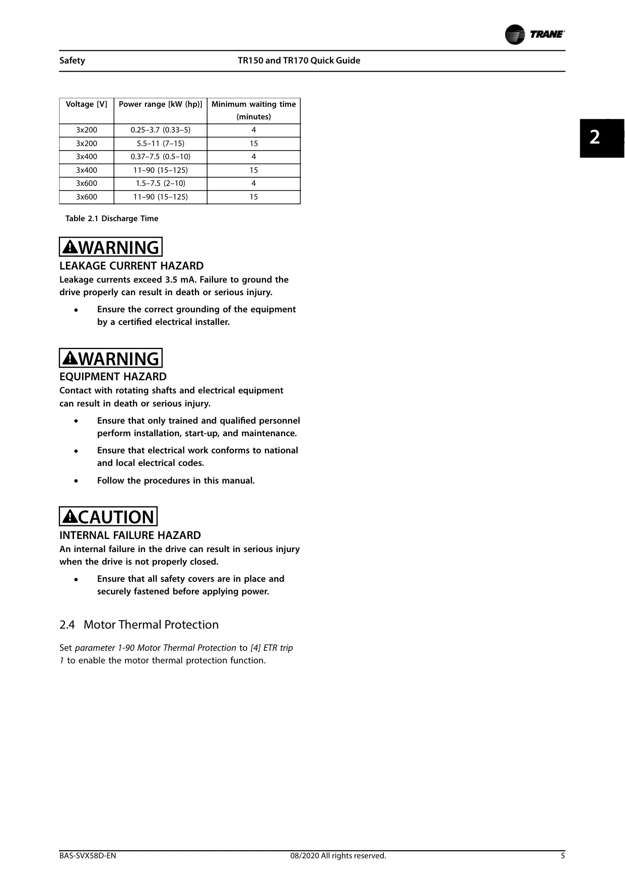
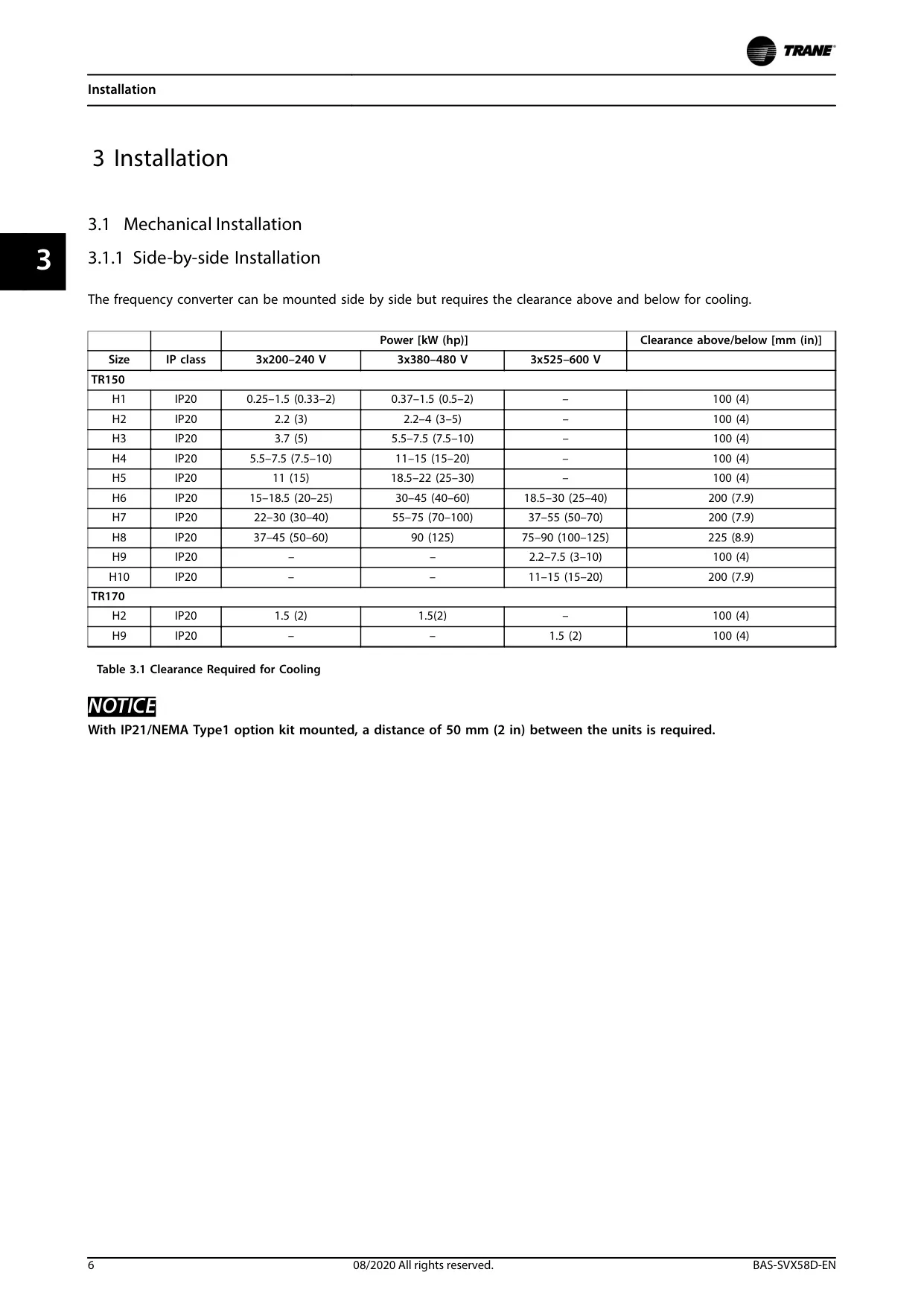
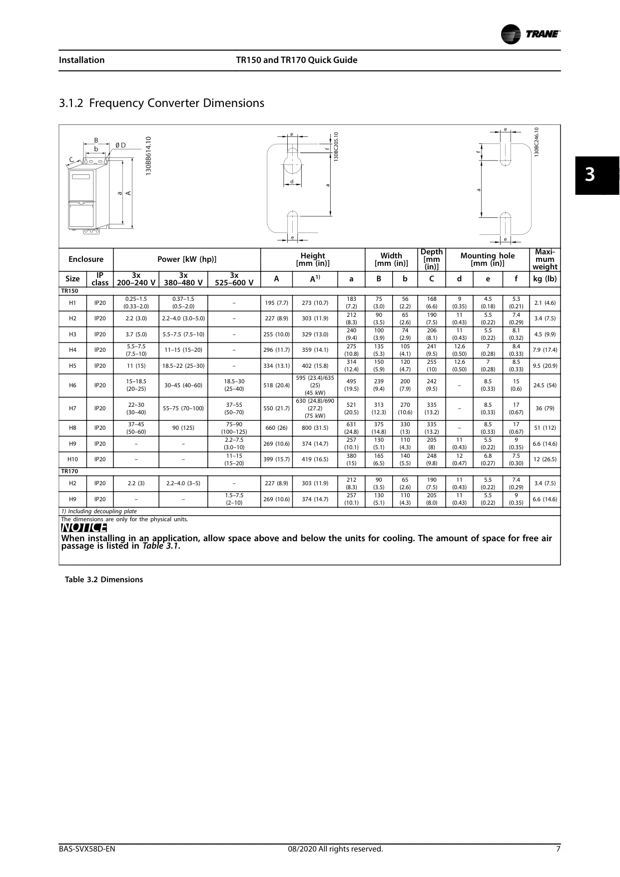





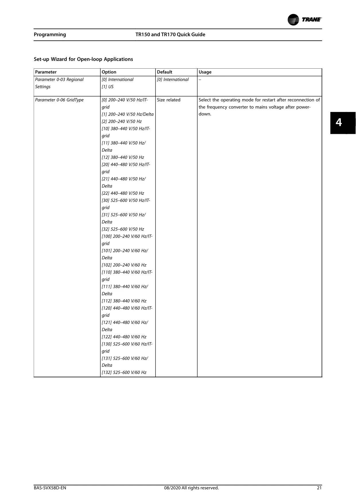
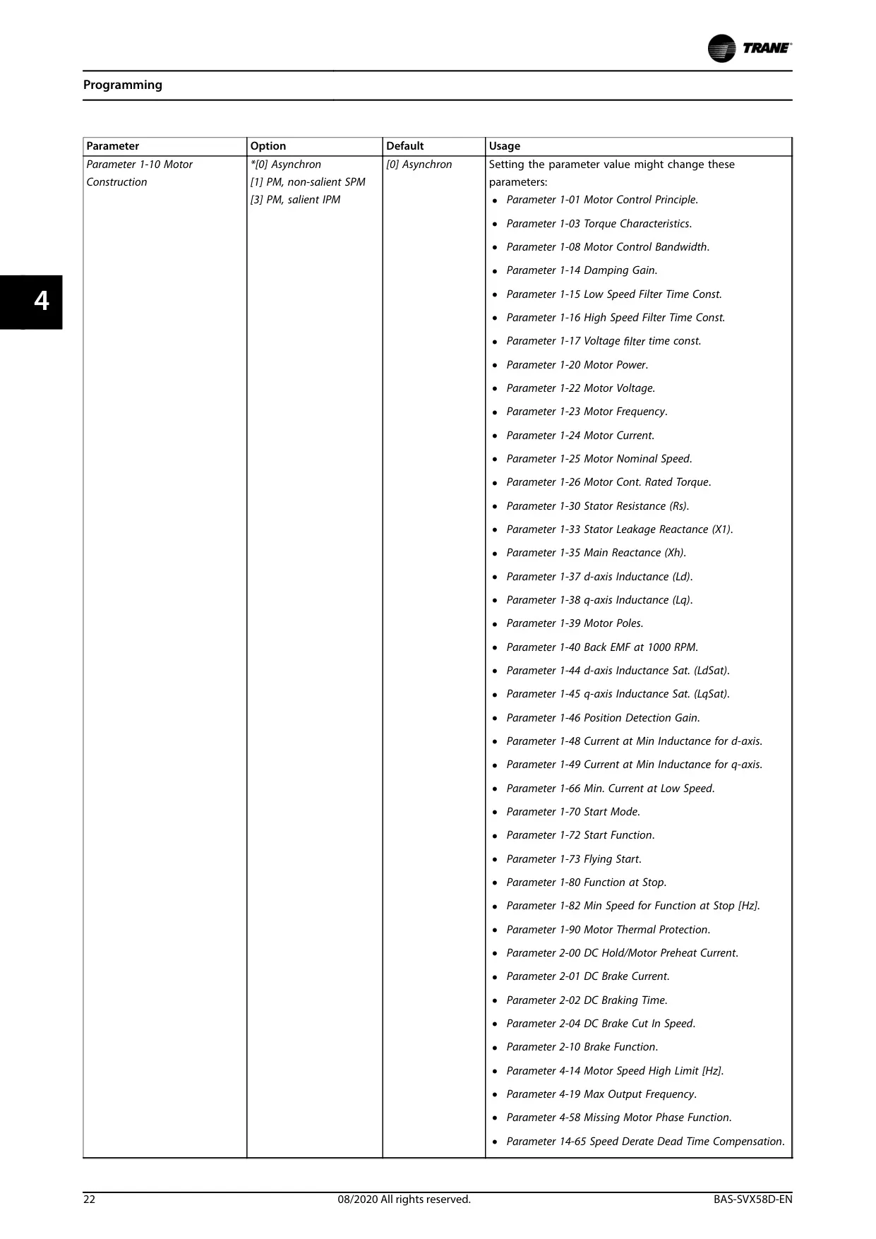


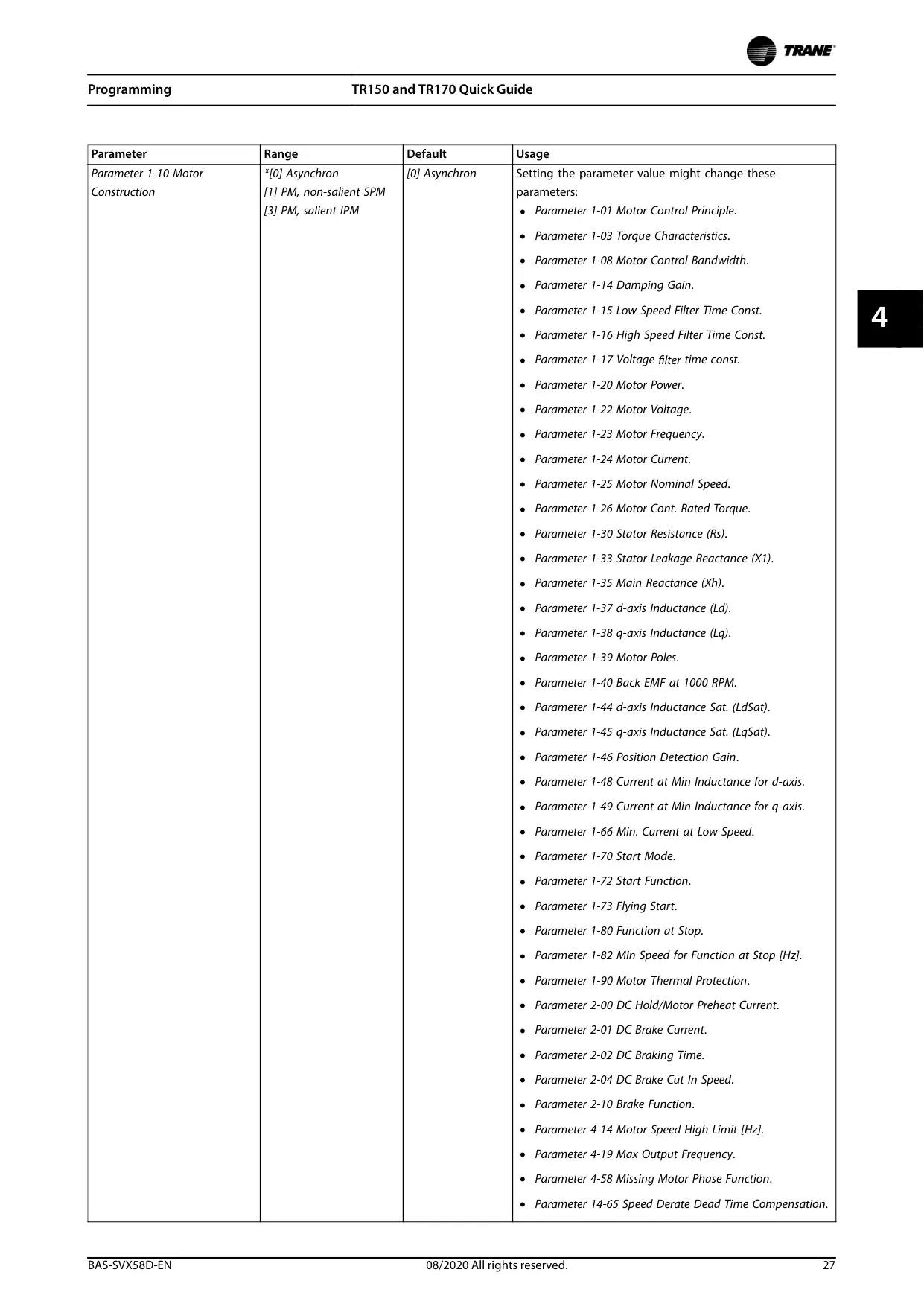
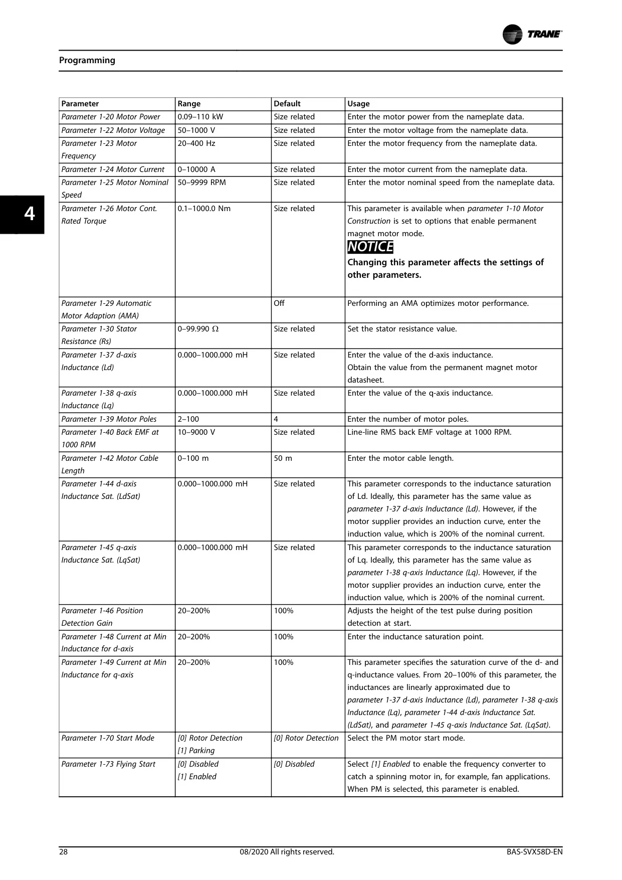
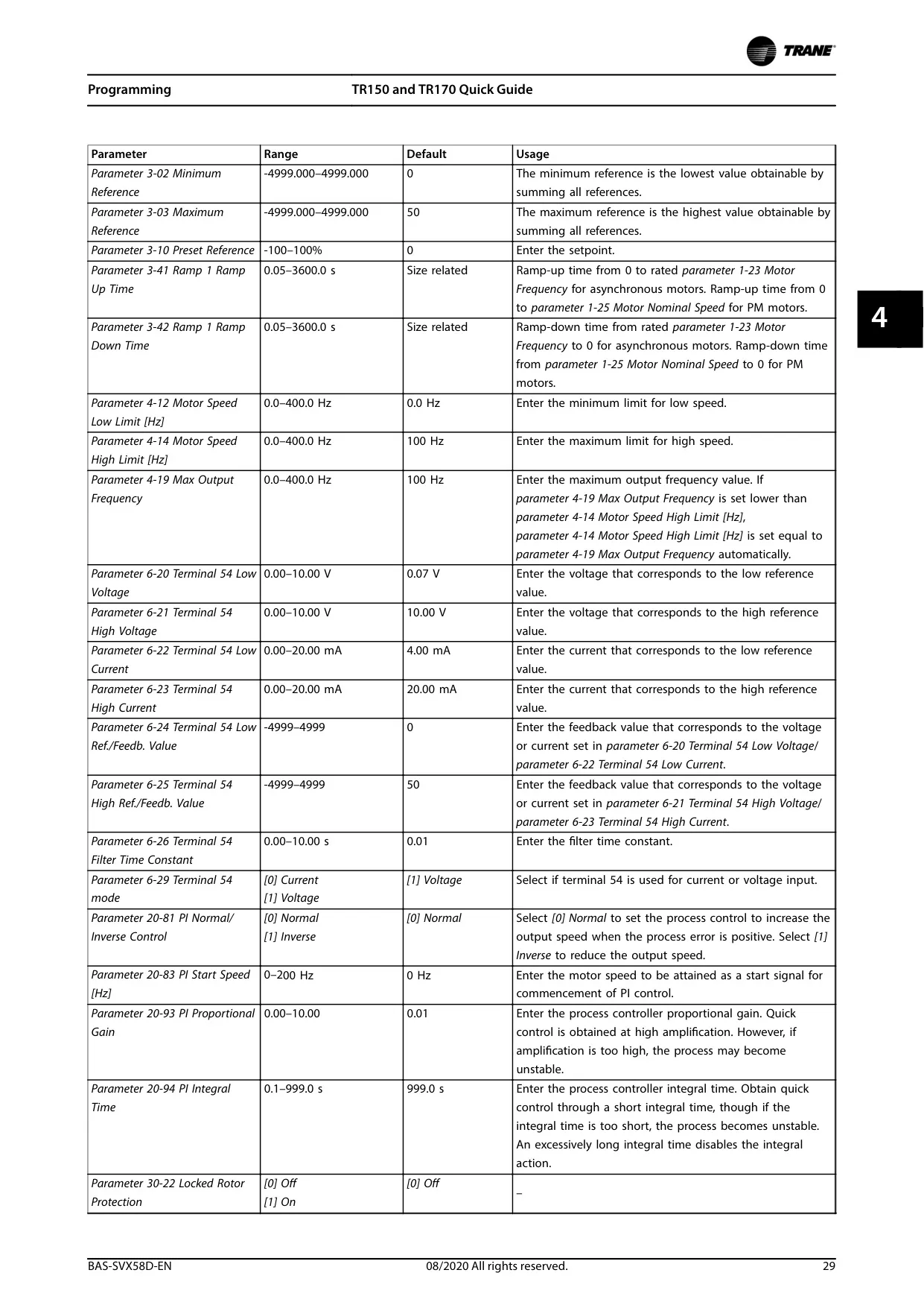


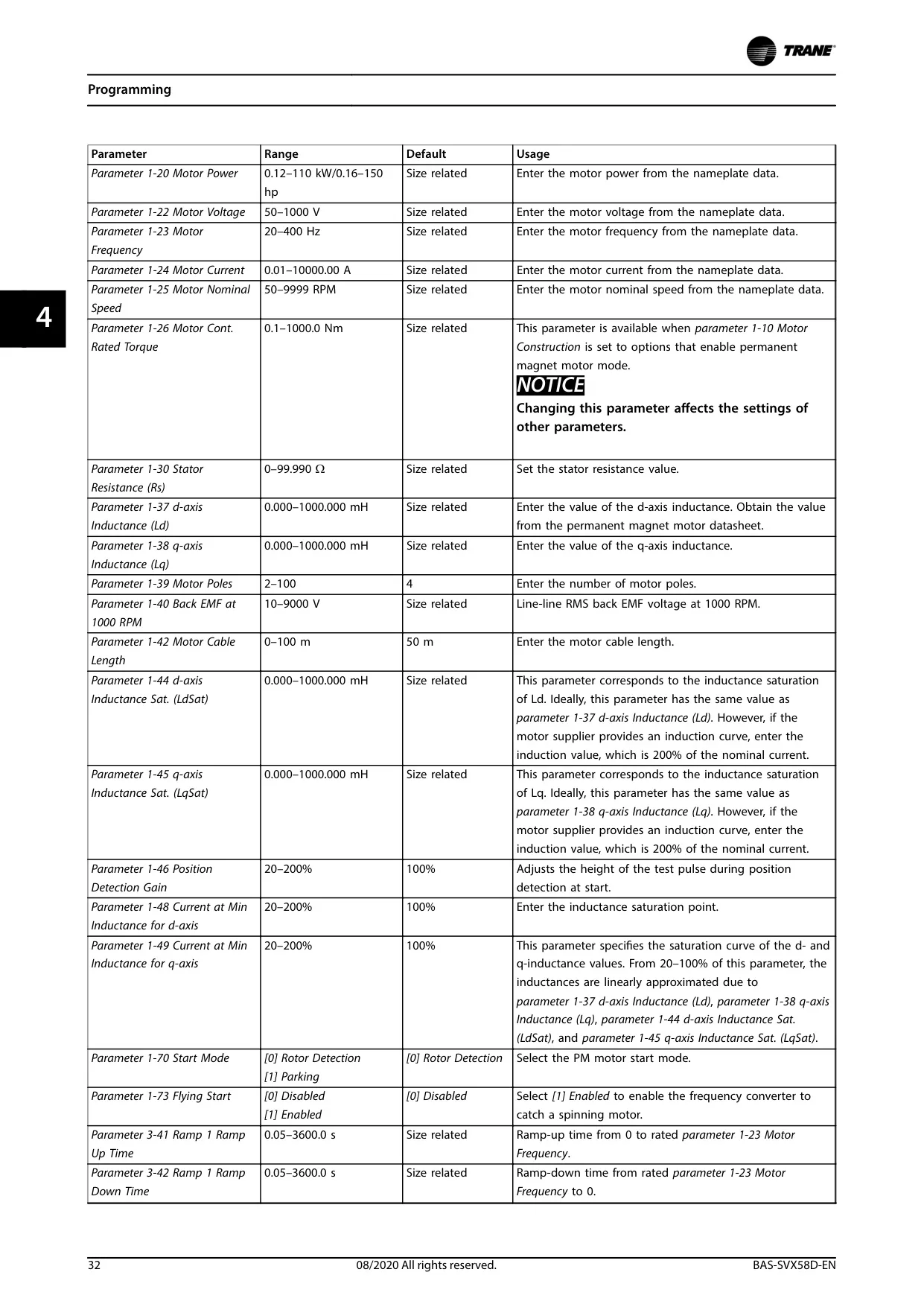
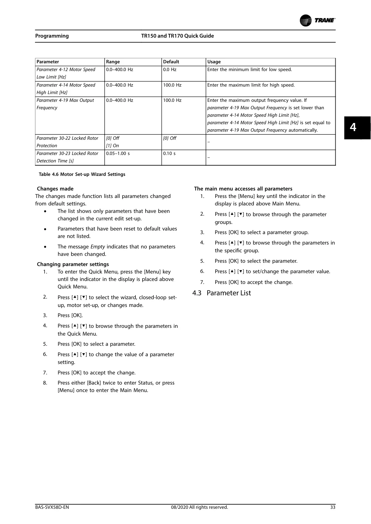
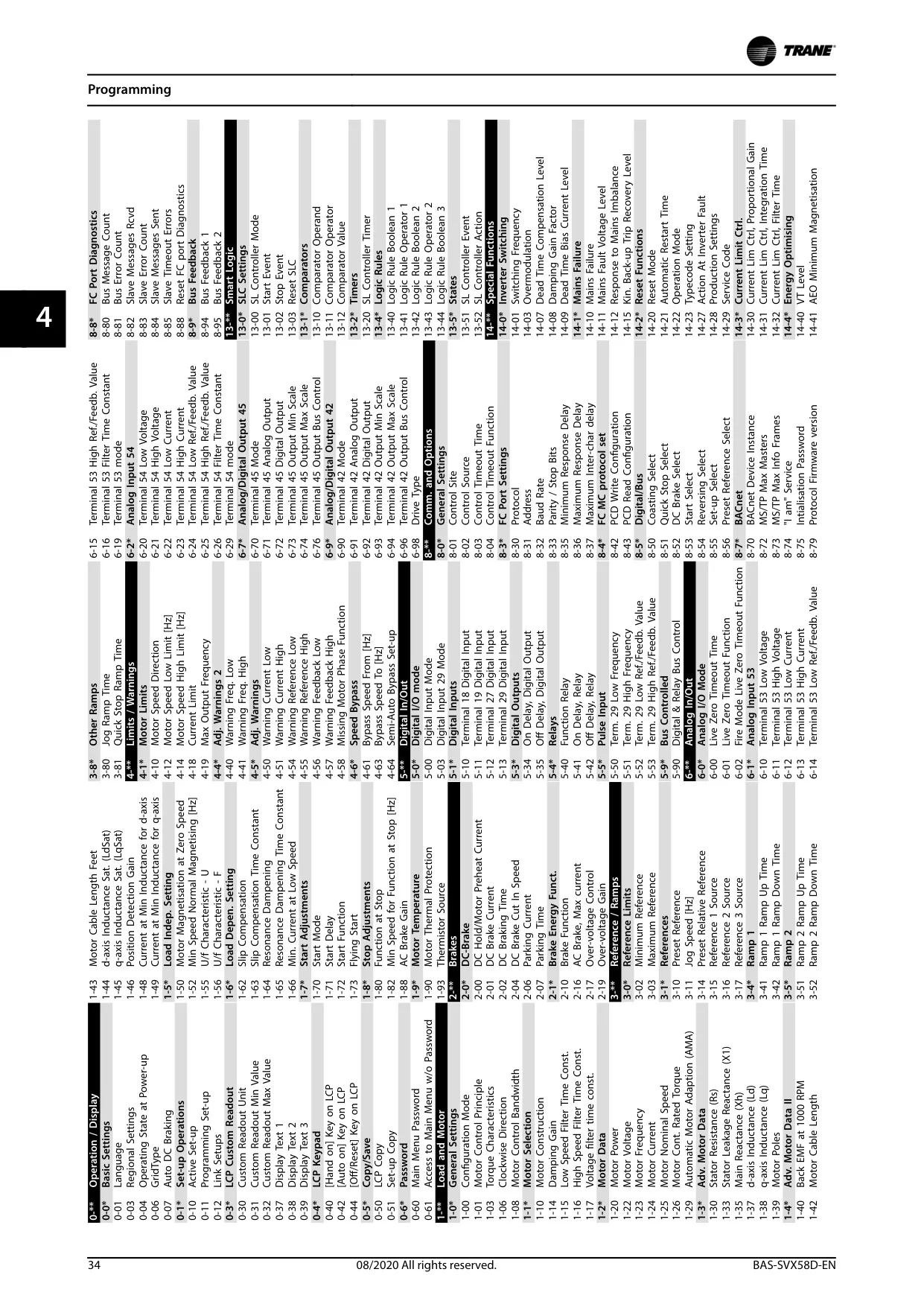
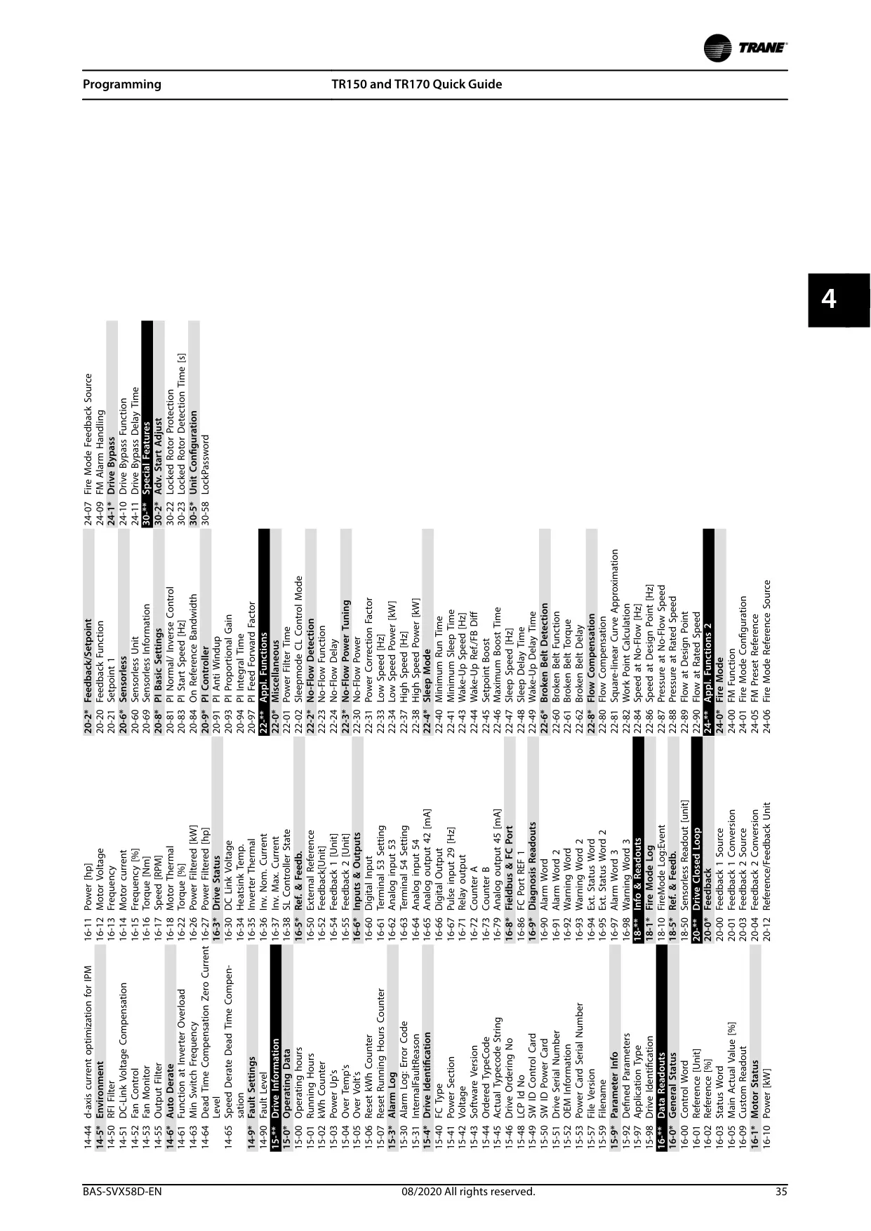
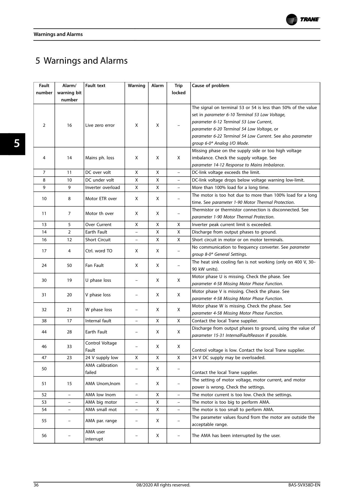
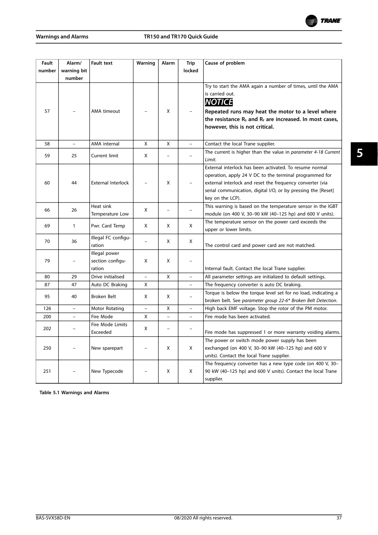
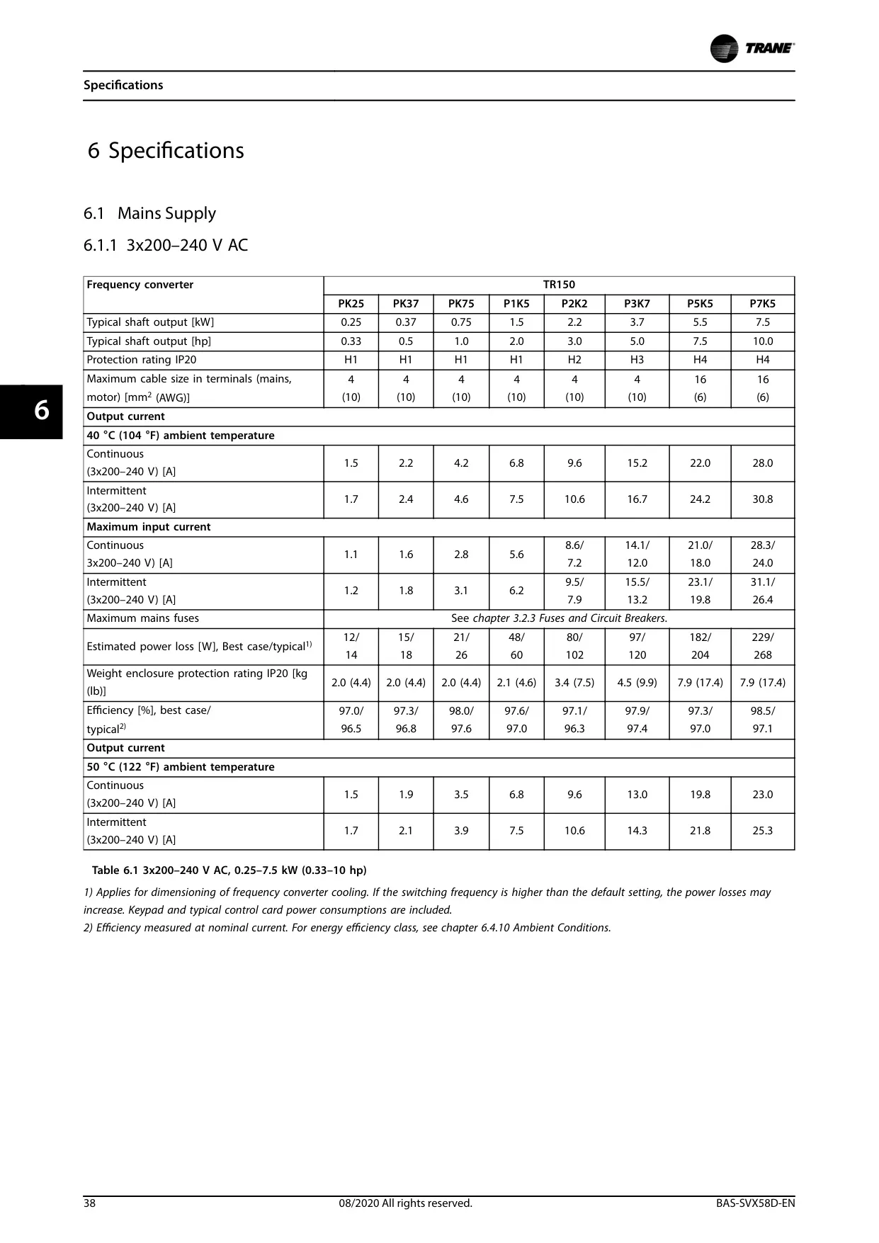

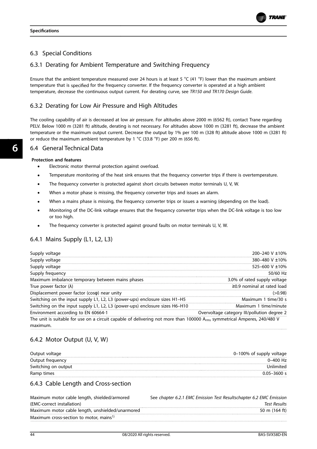
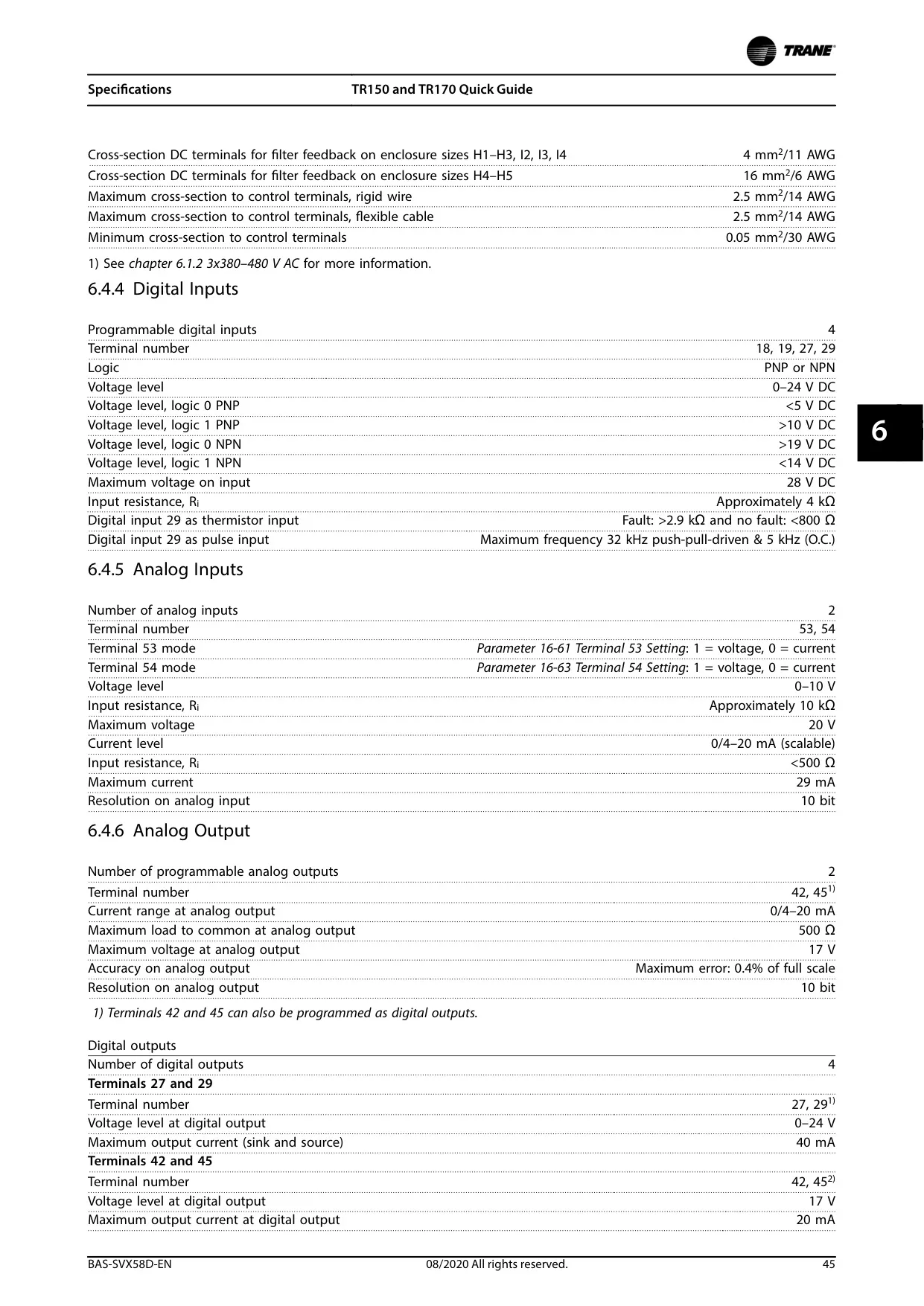
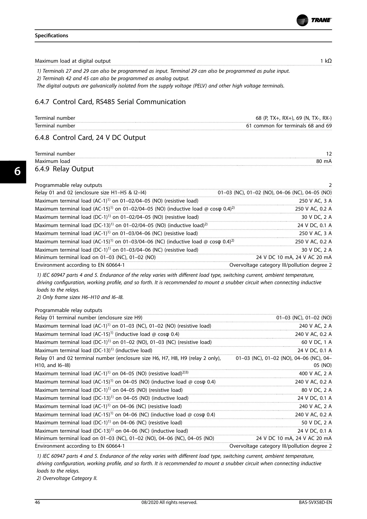
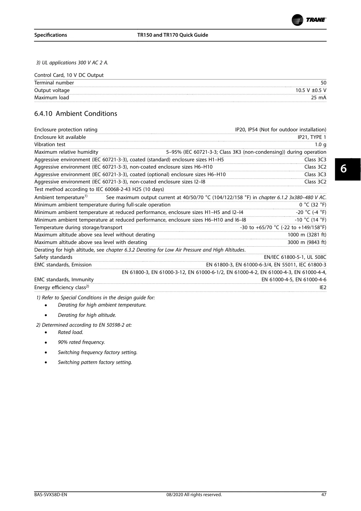
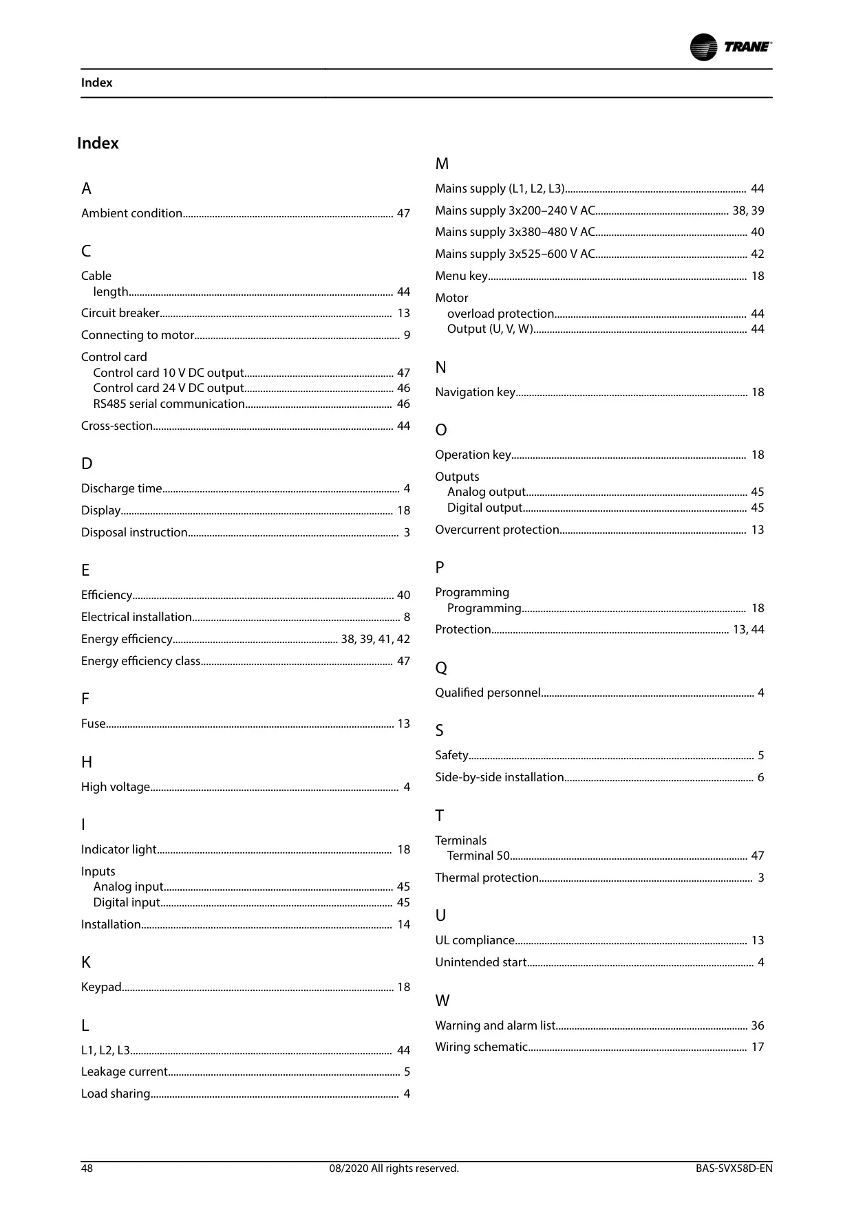
Trane TR150 Variable Frequency Drive

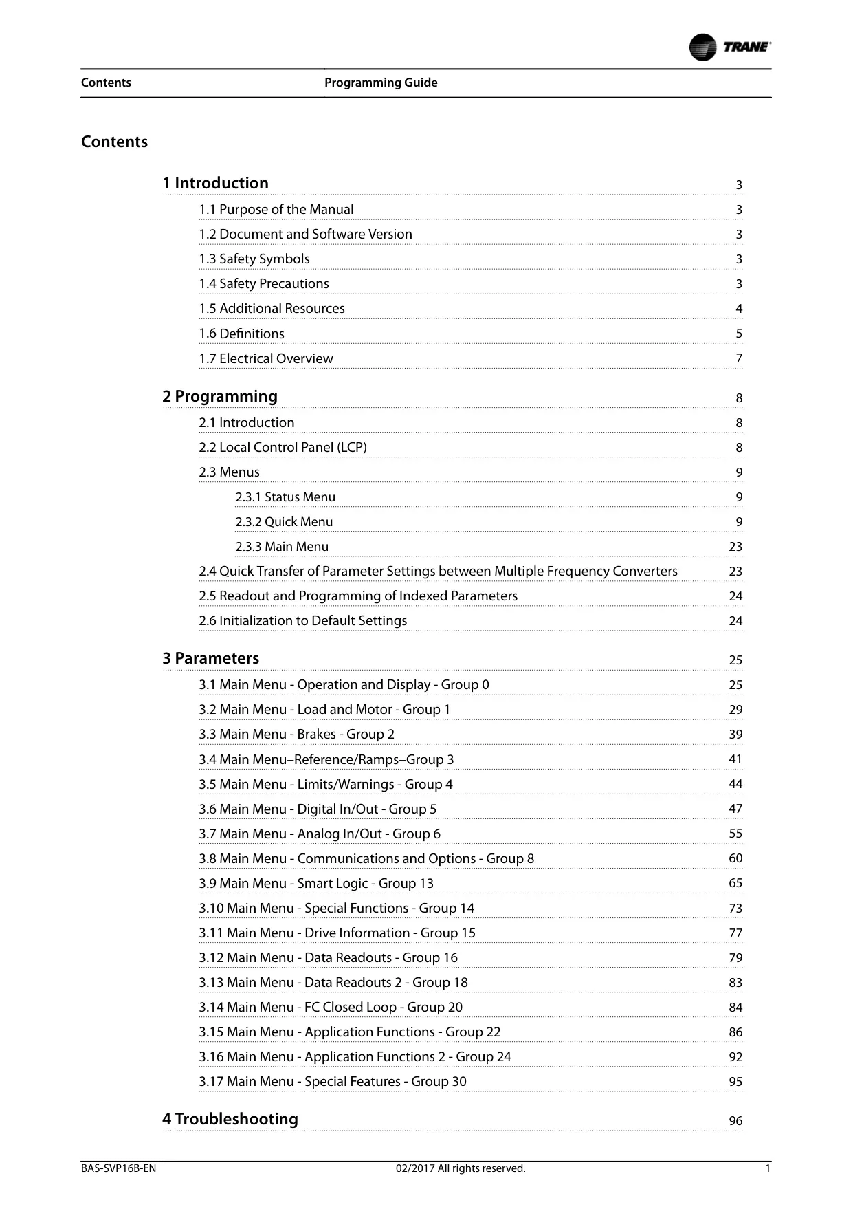

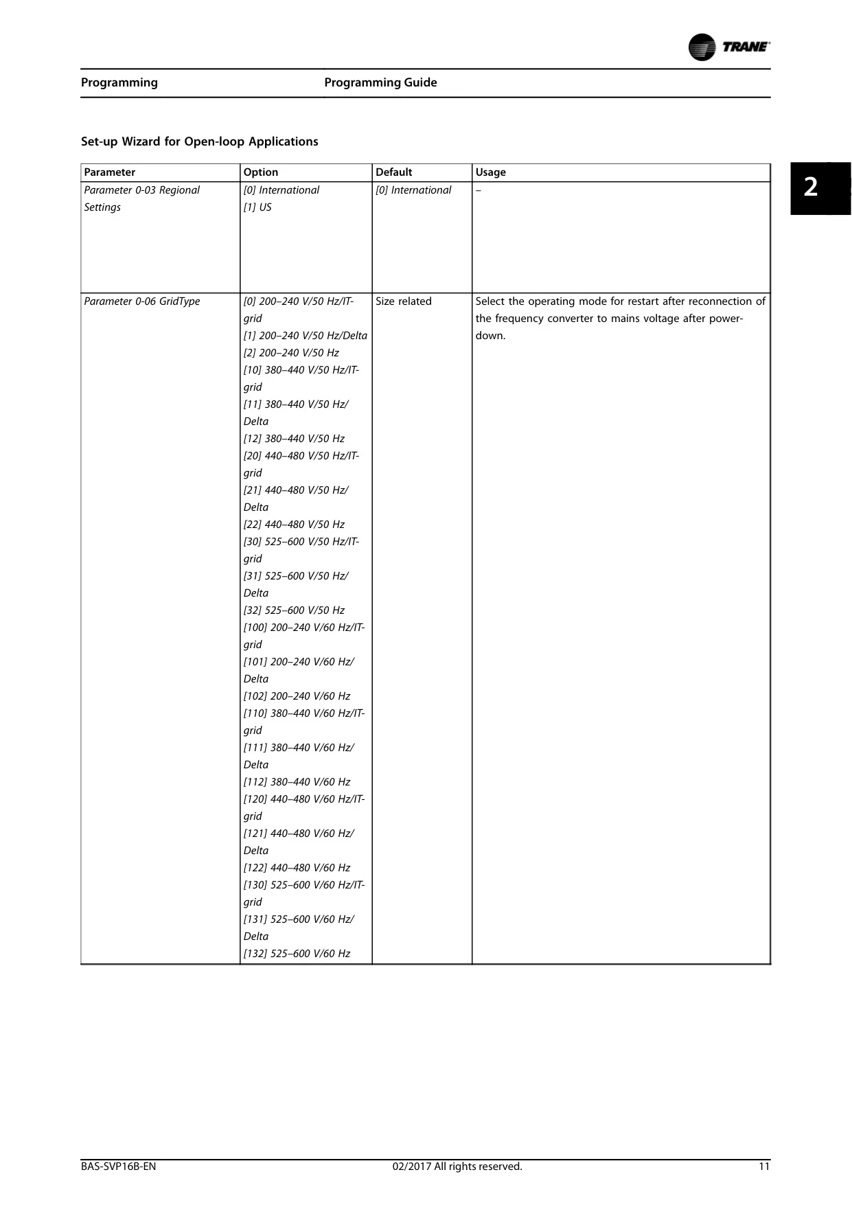
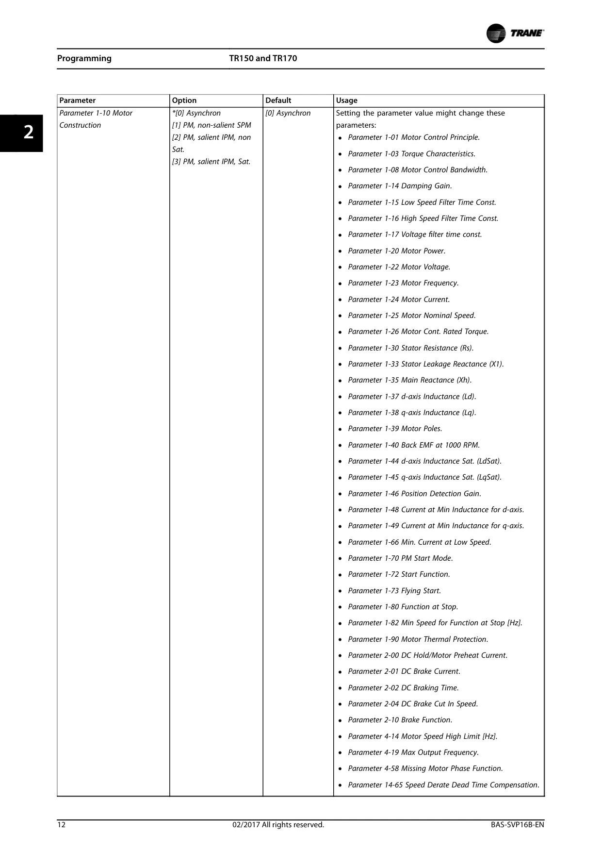
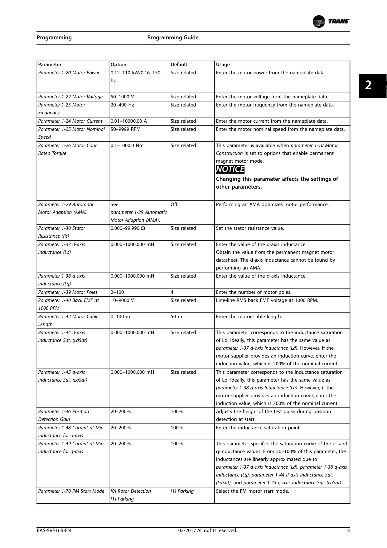
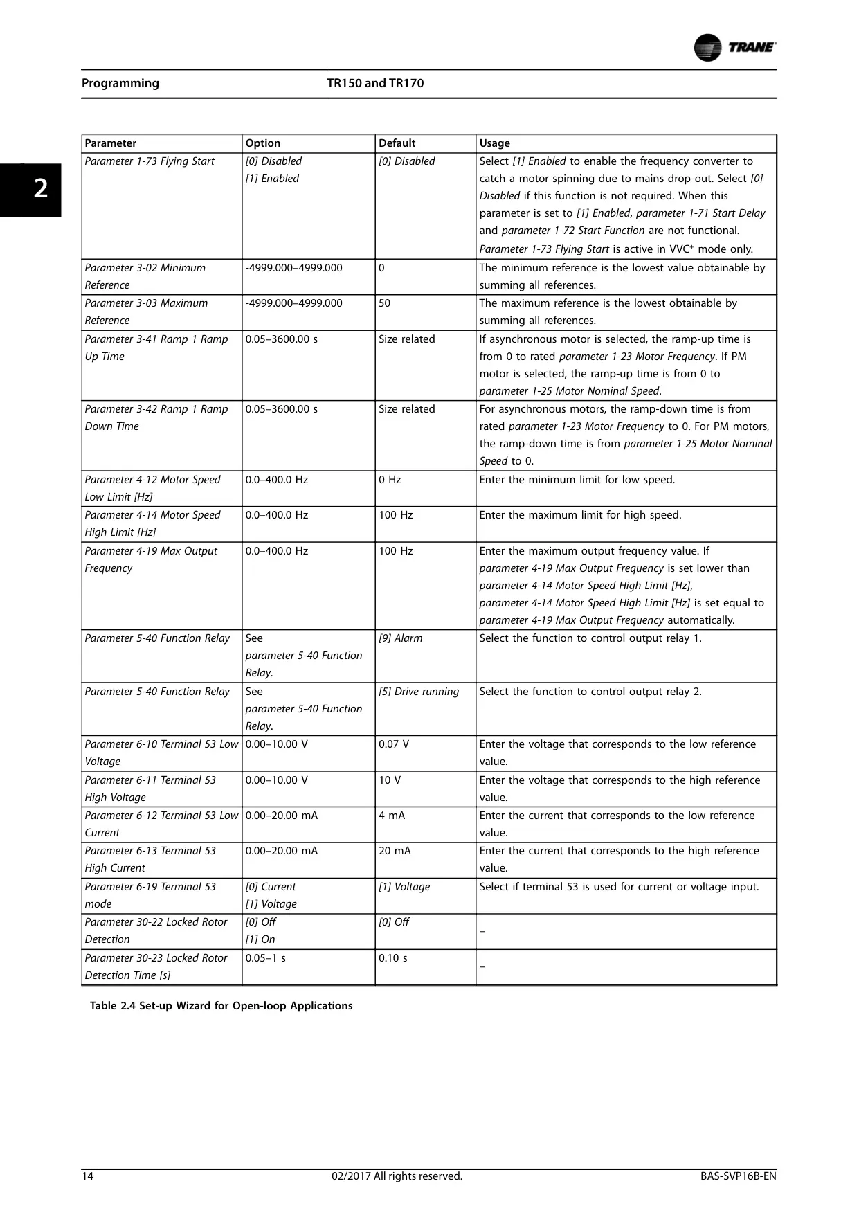
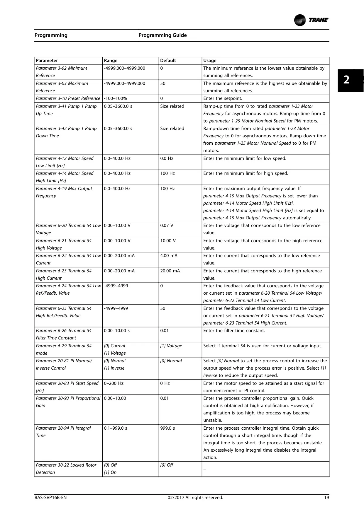

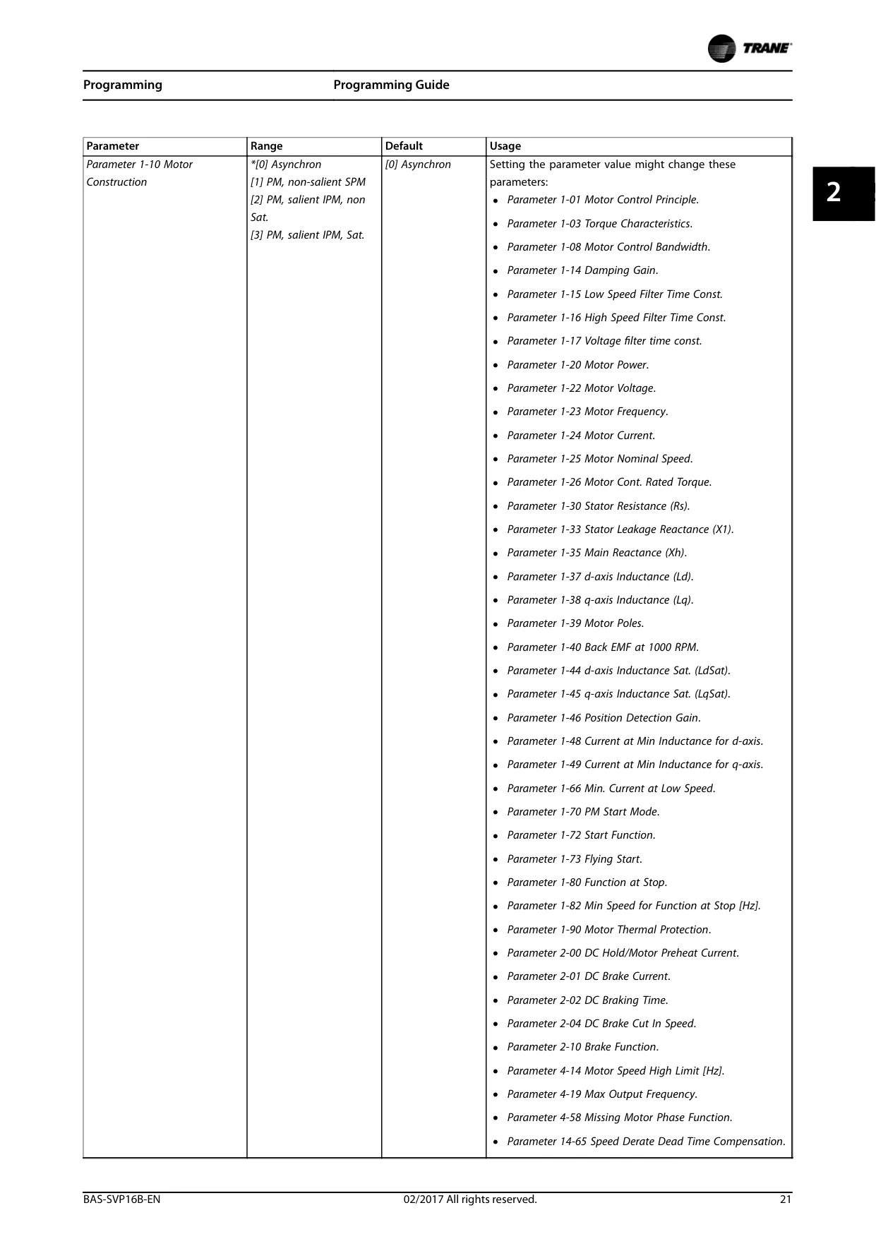
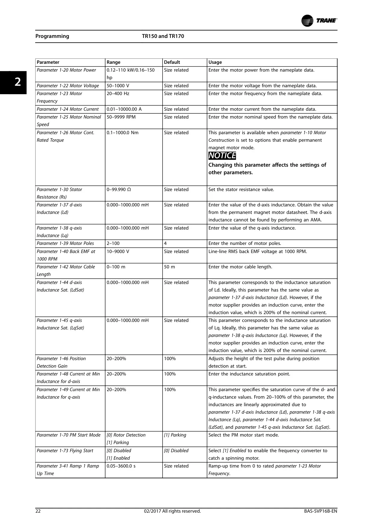
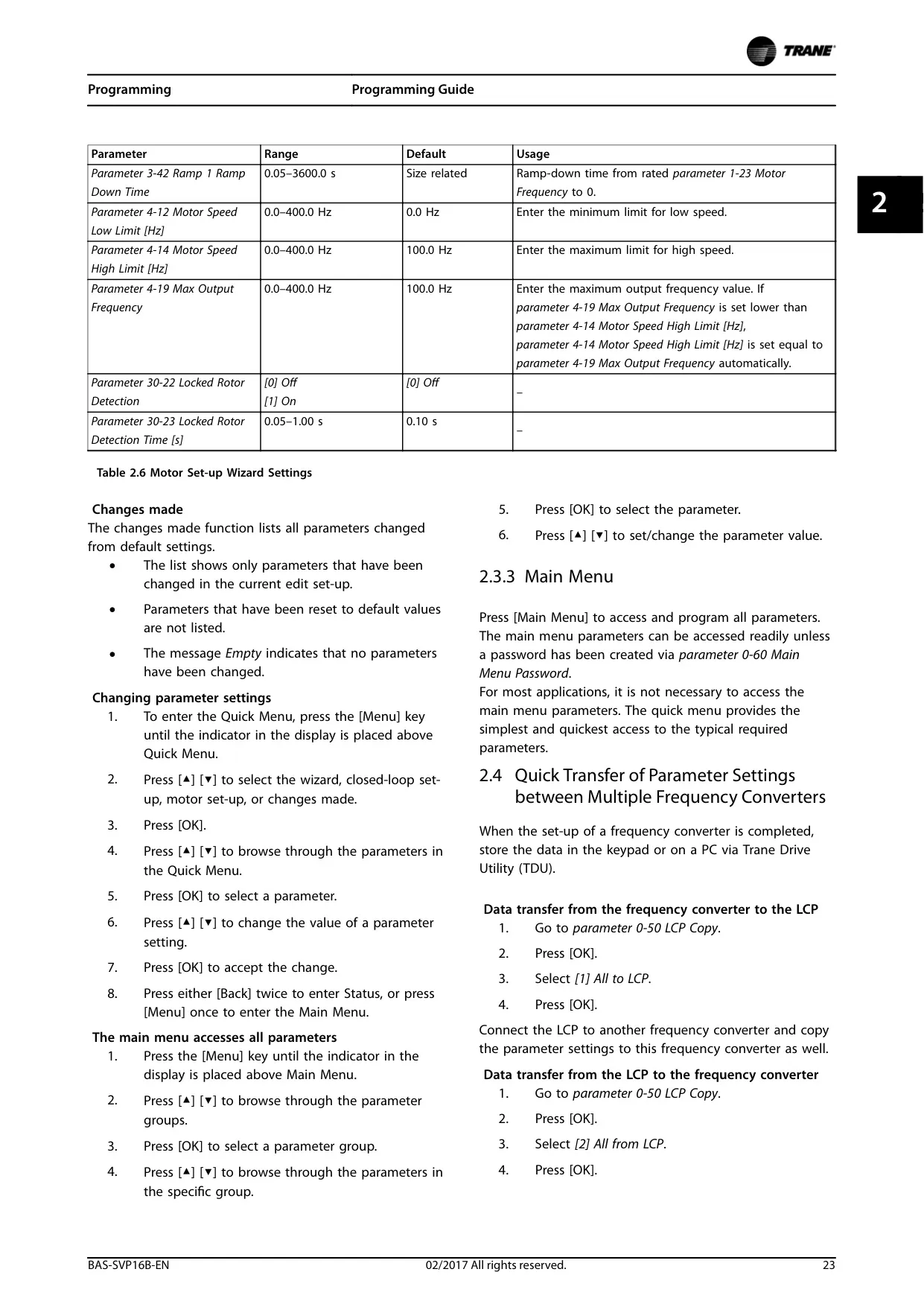
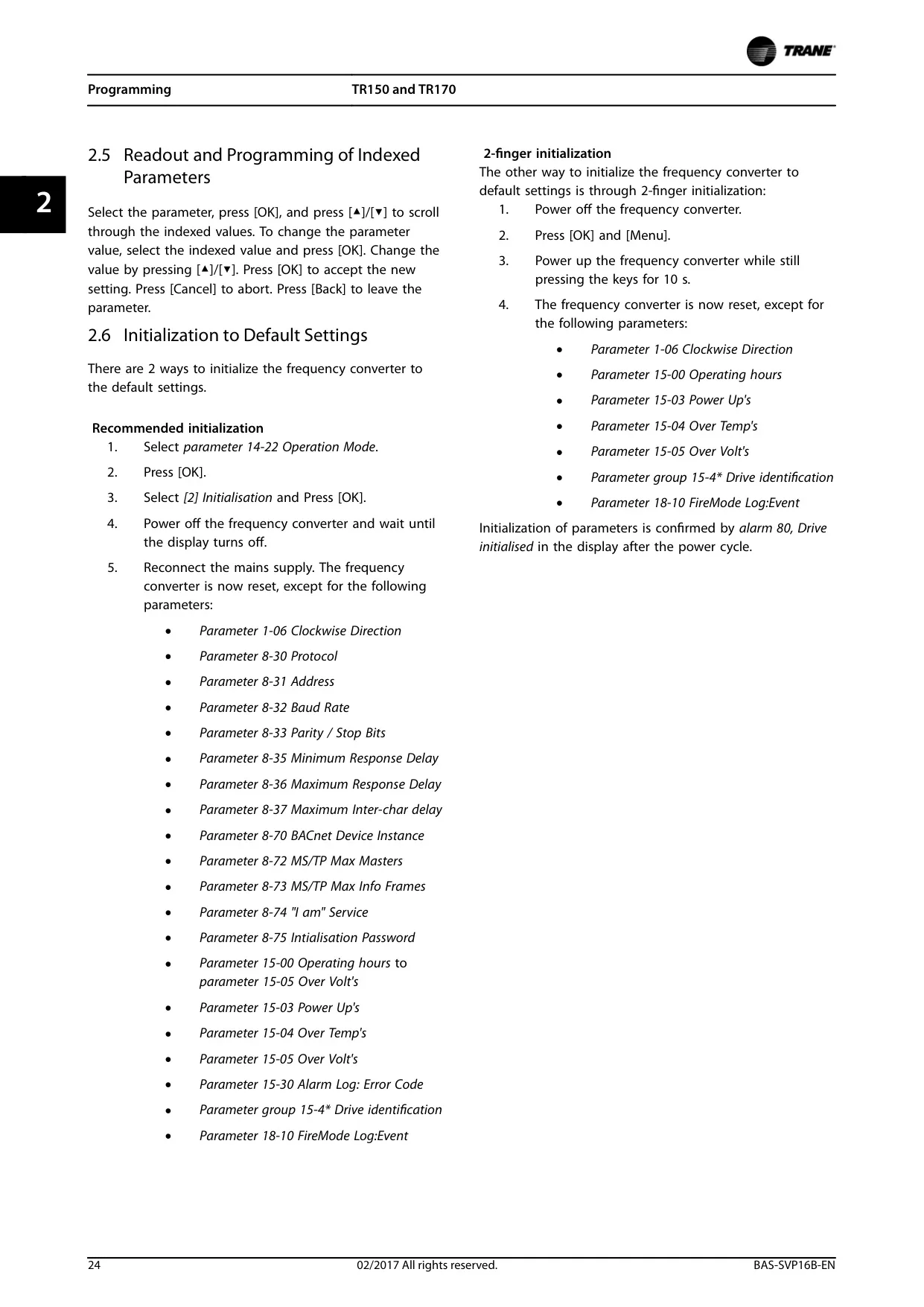
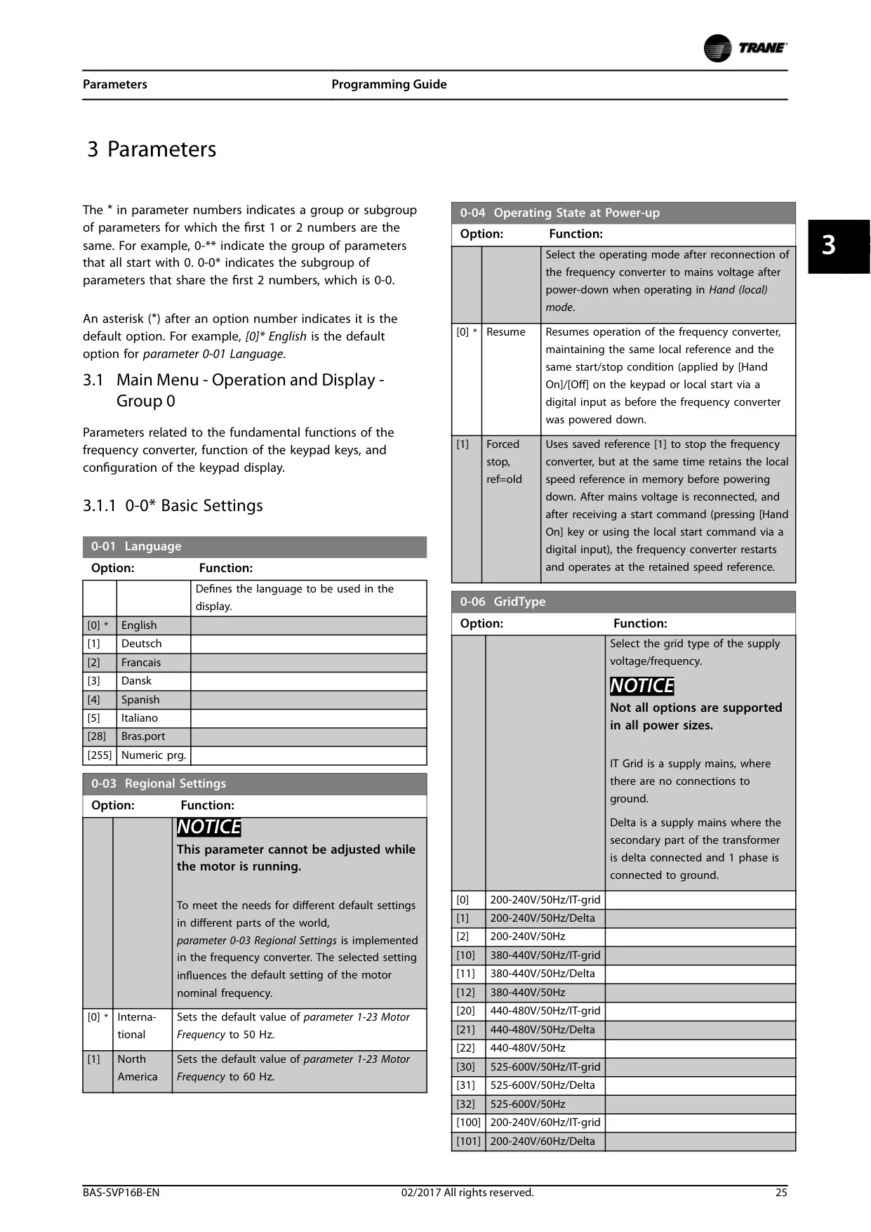
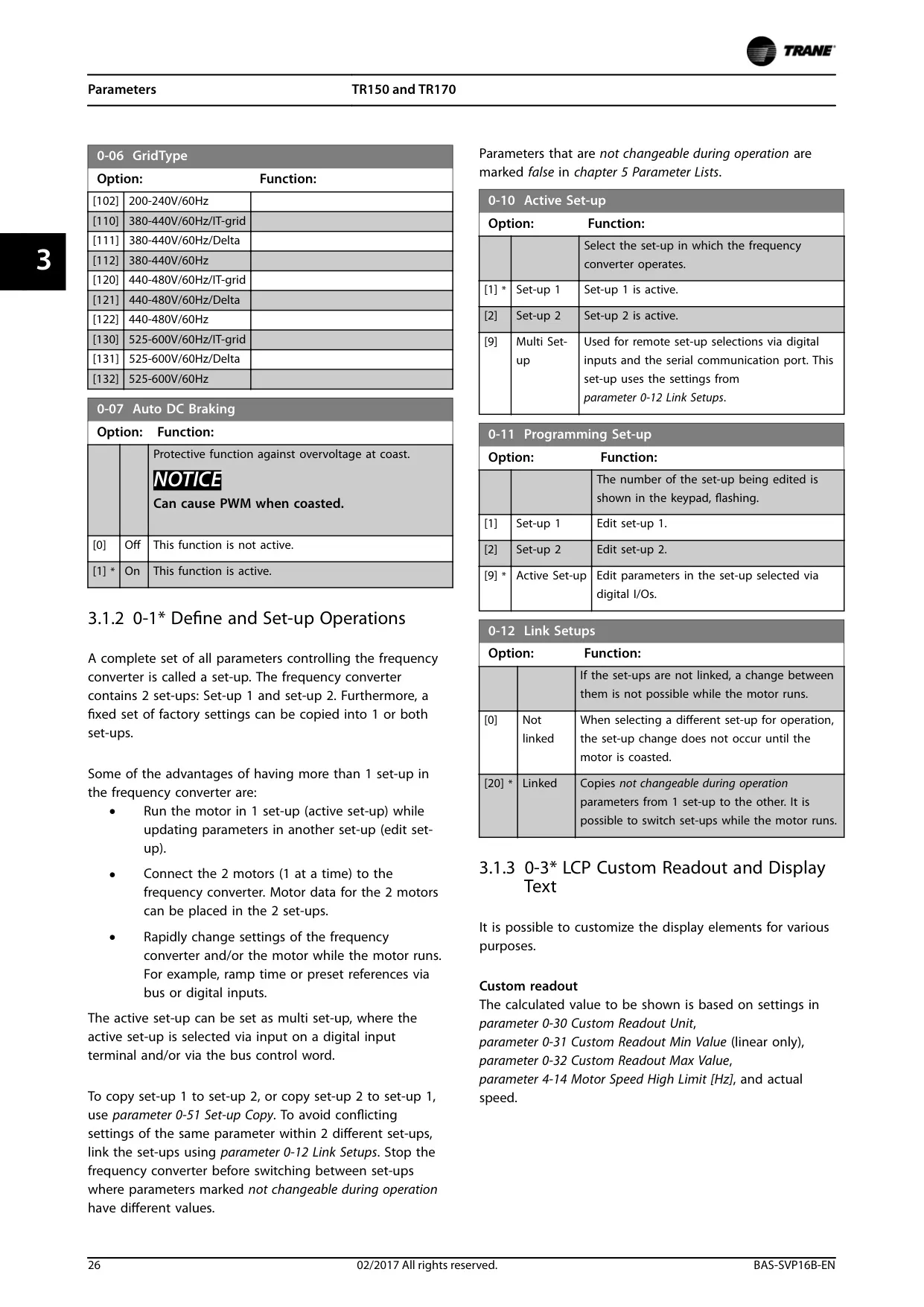


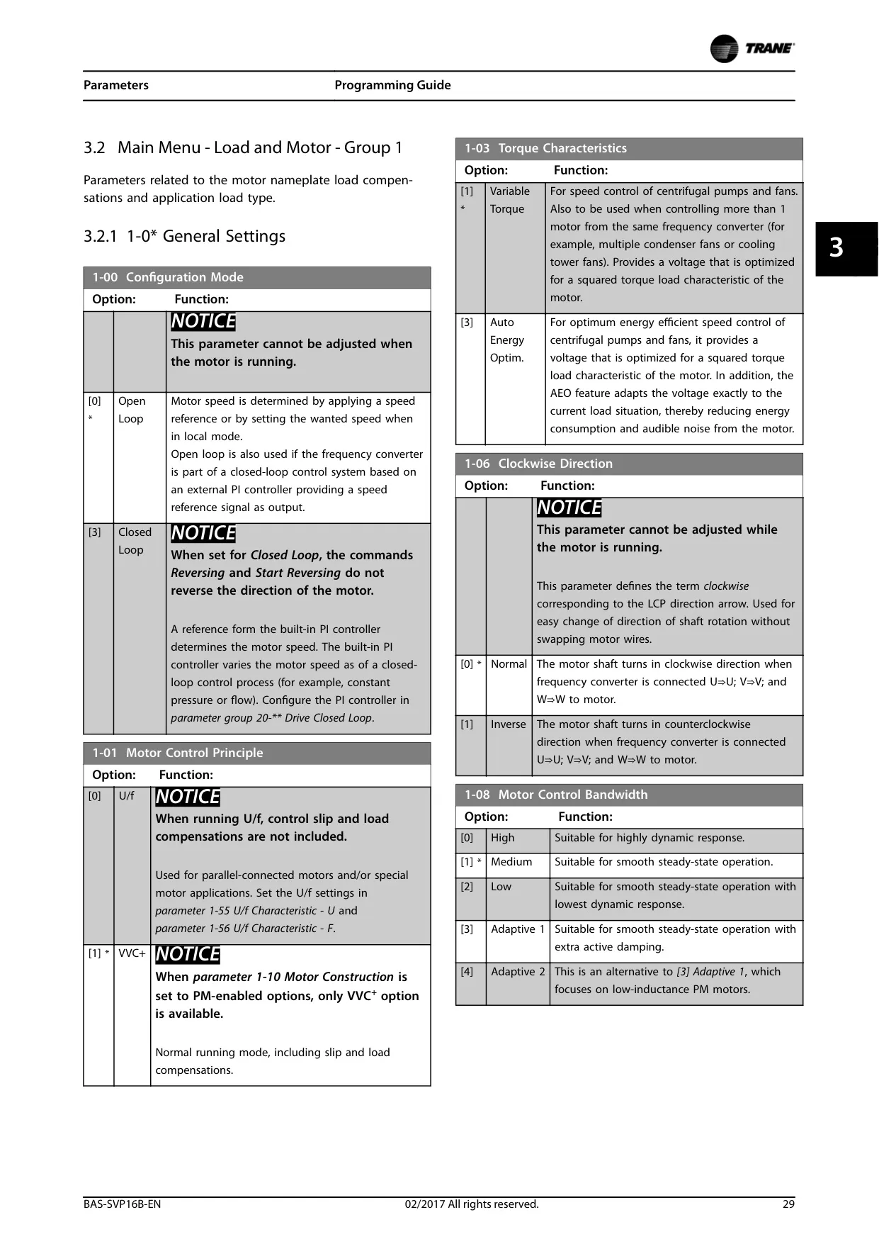
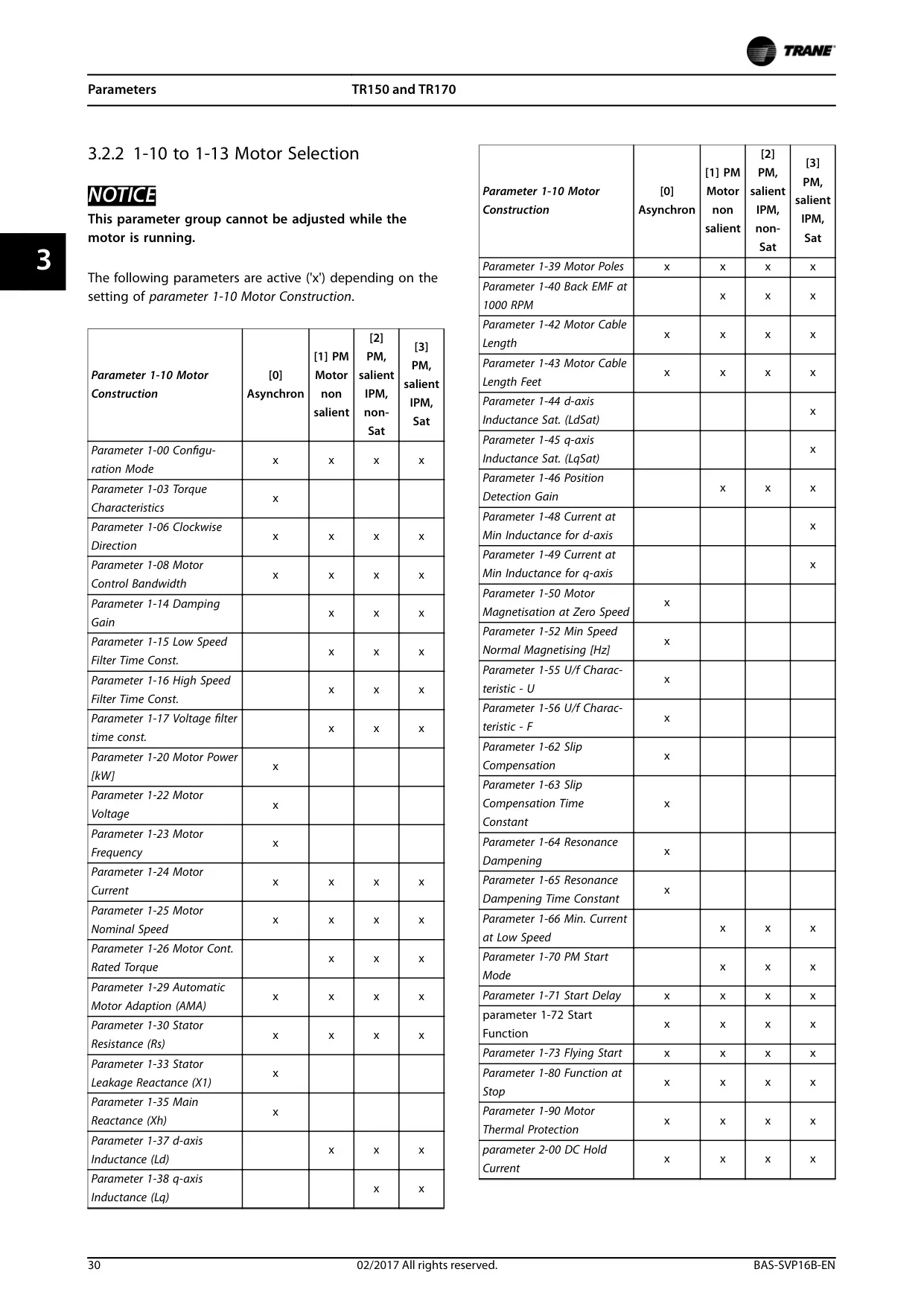
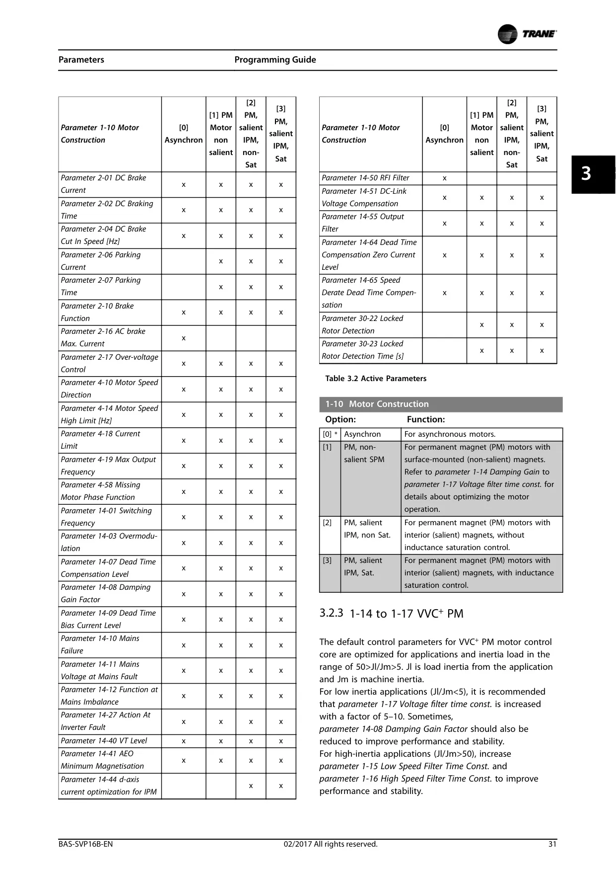
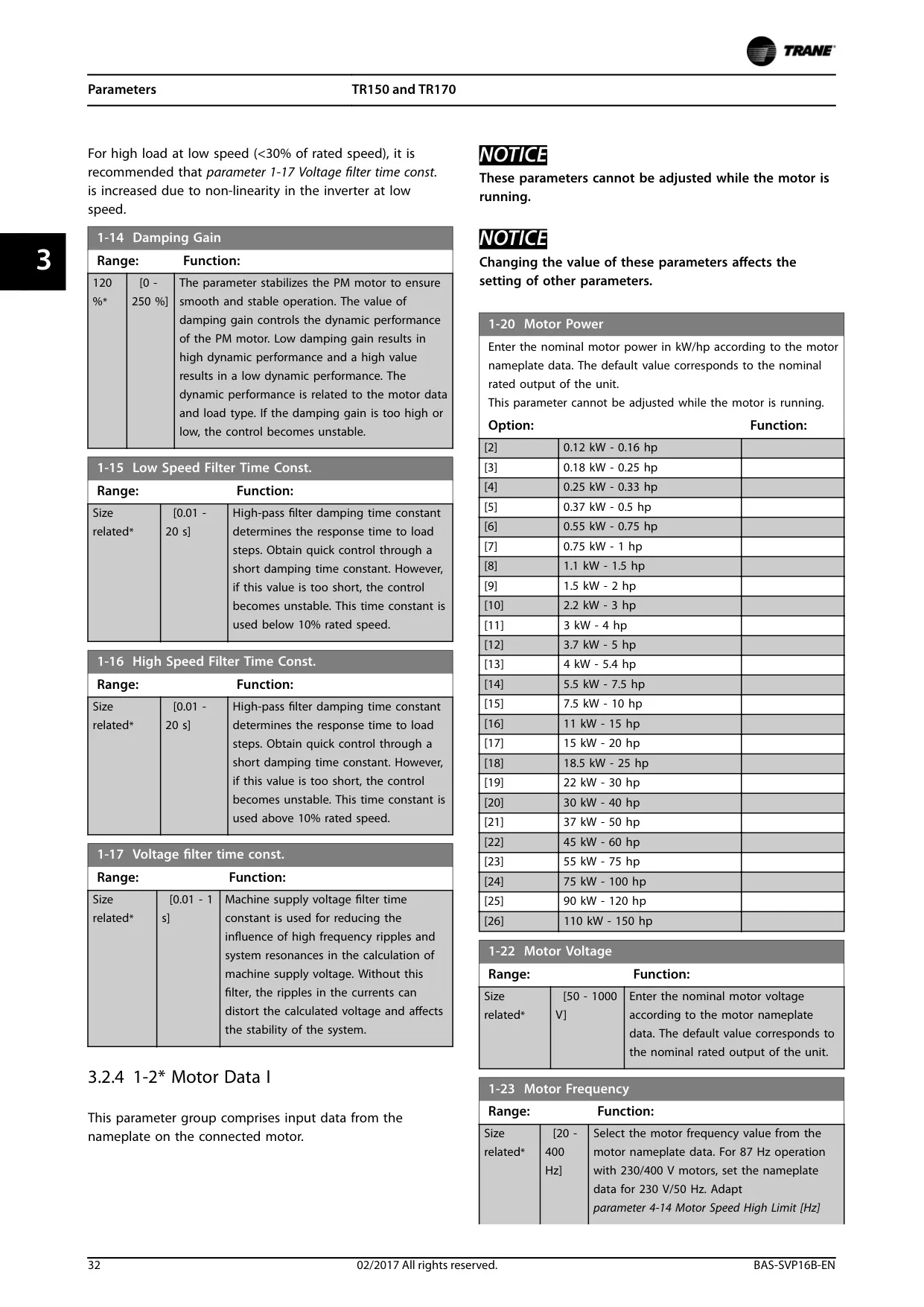
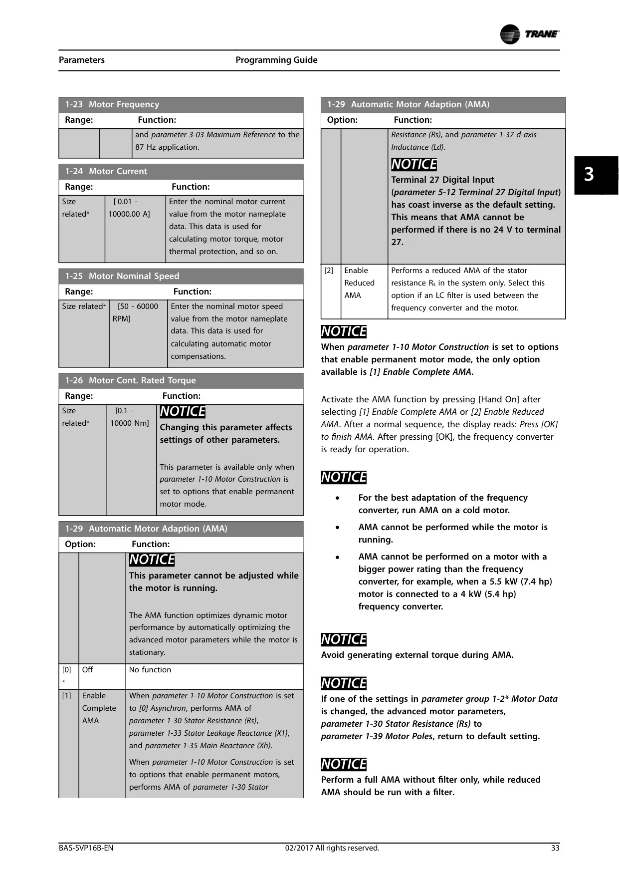
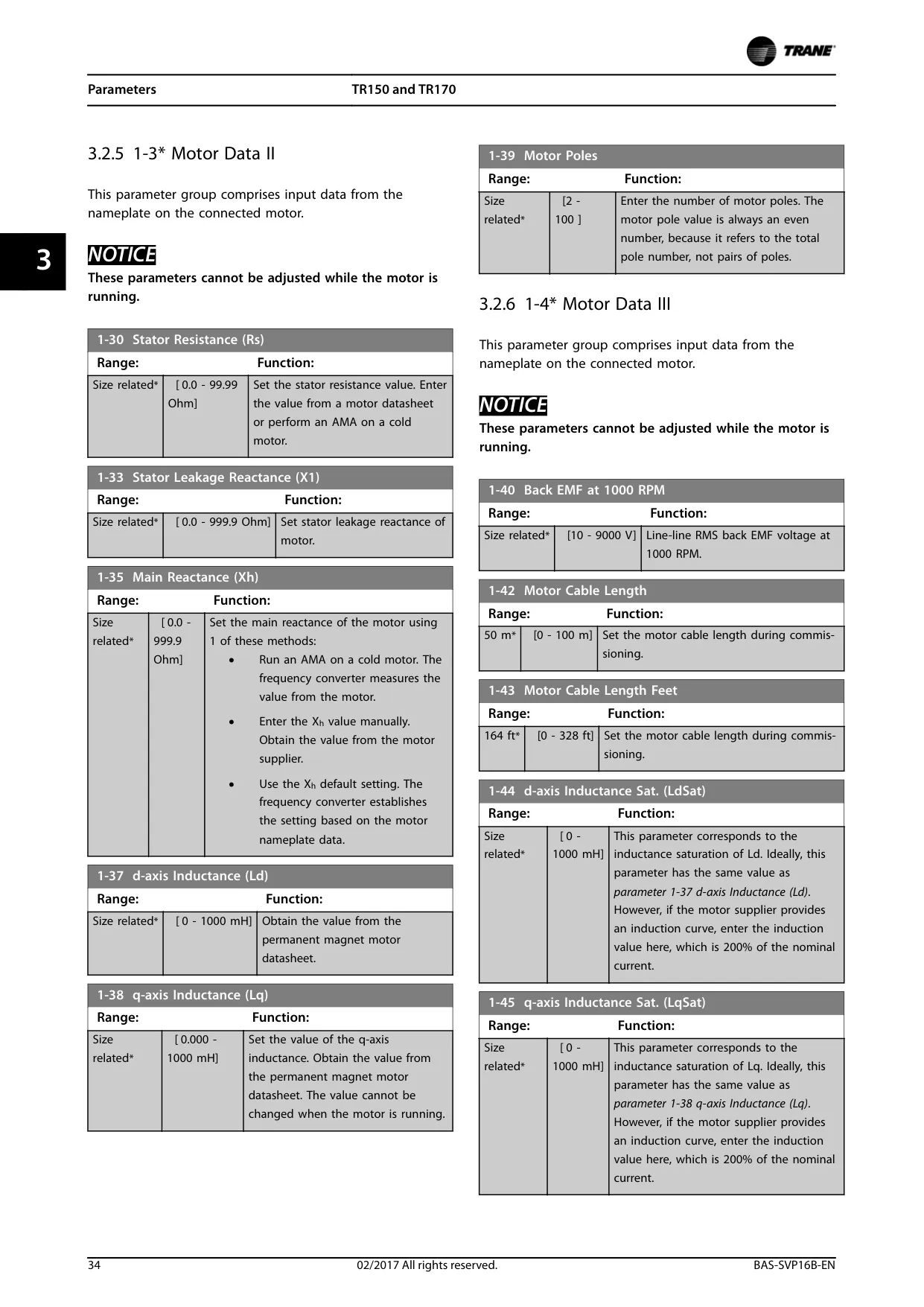
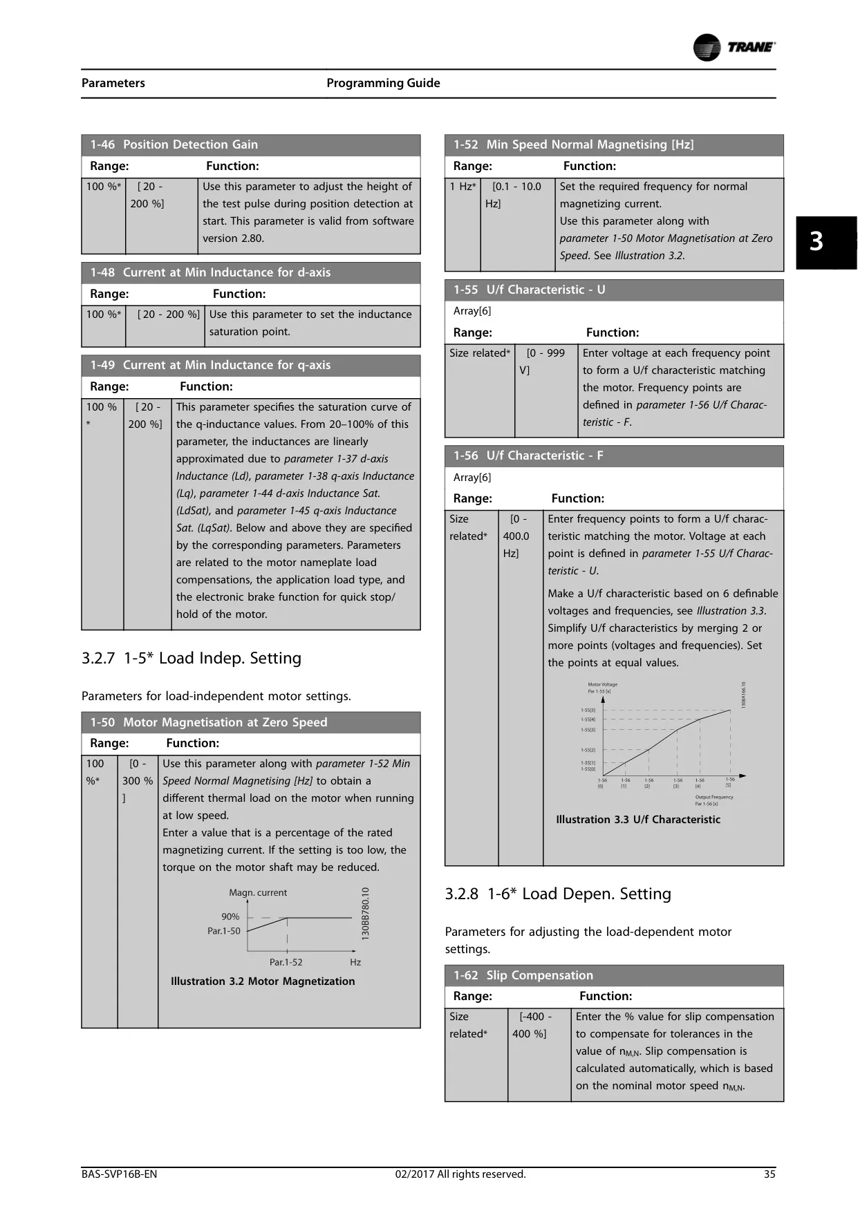
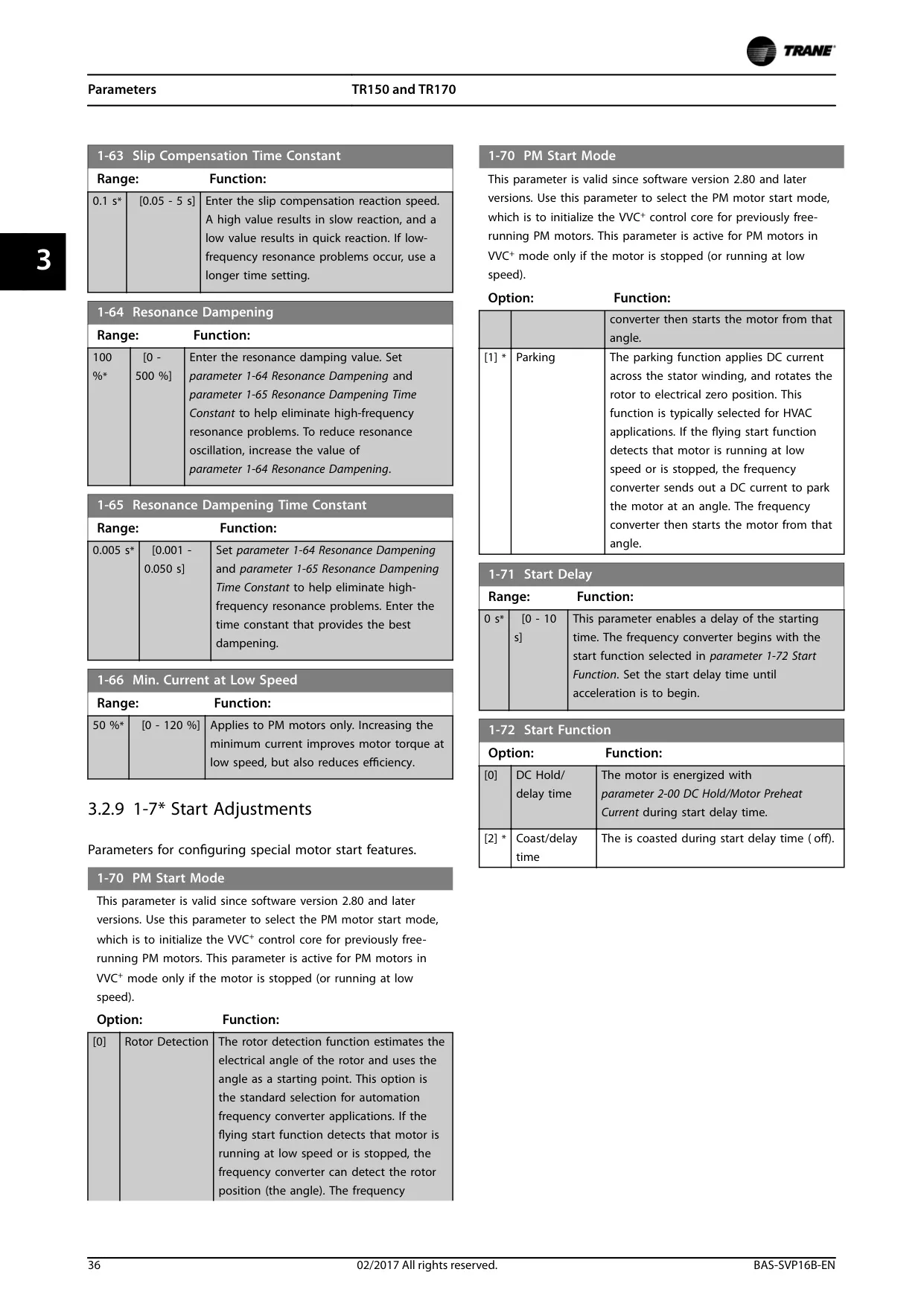

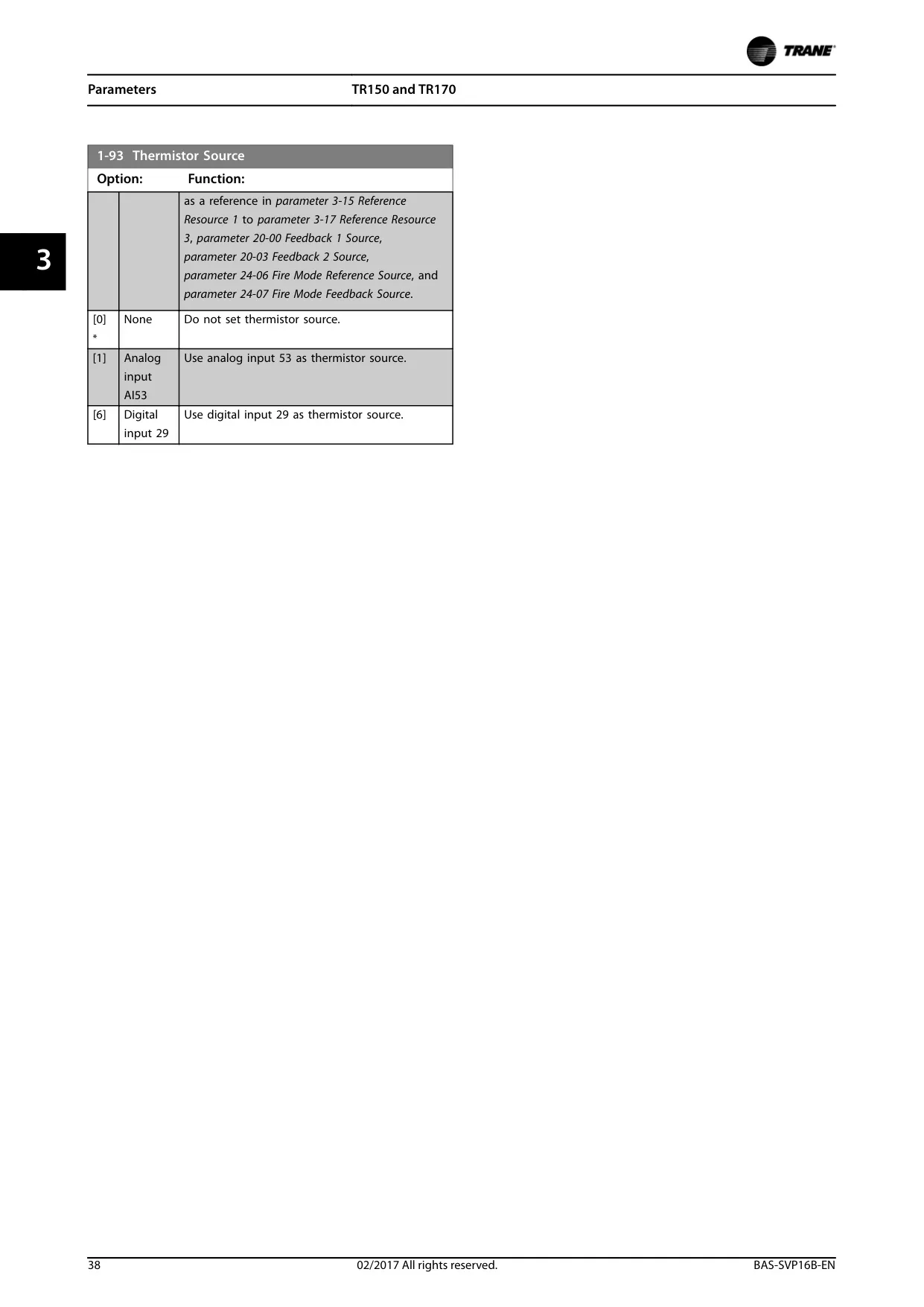
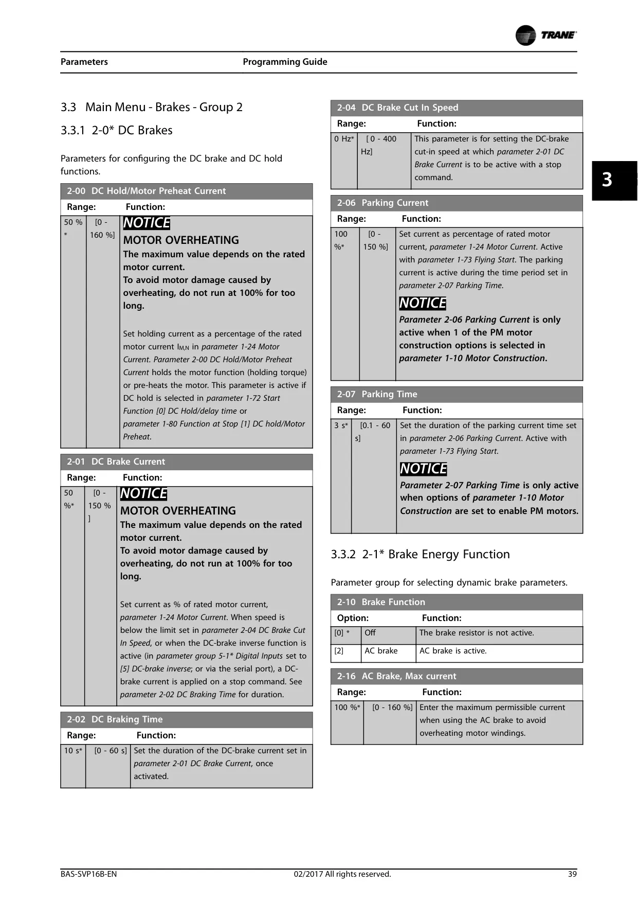
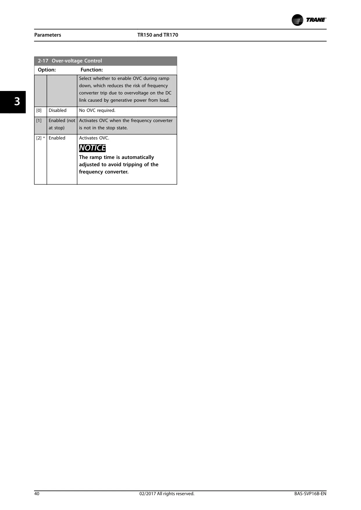
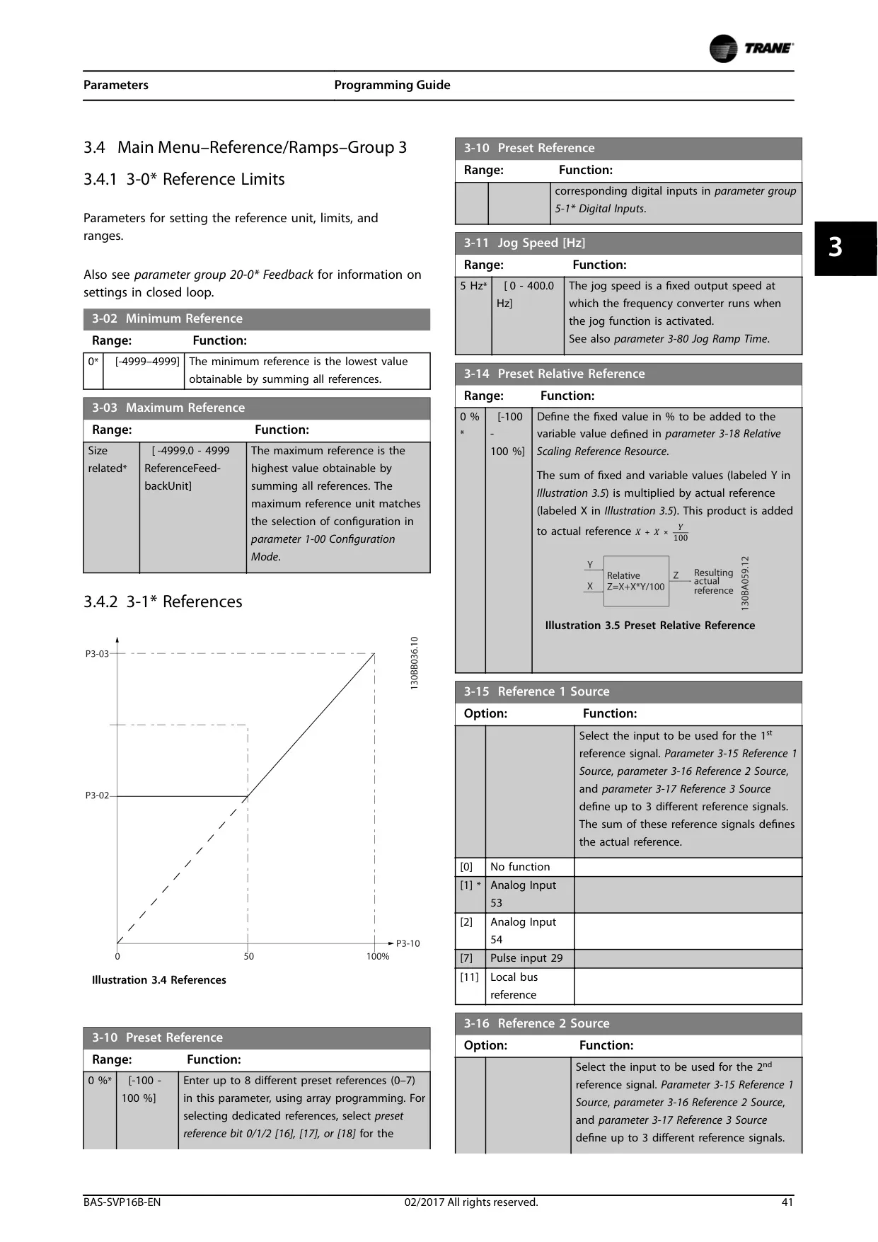
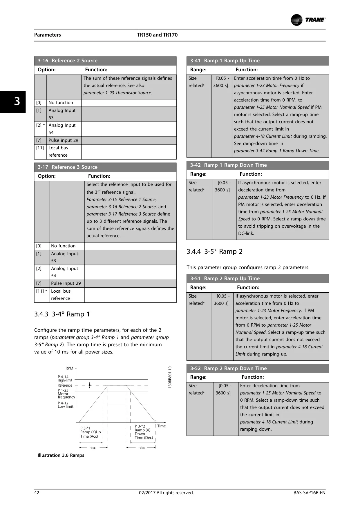
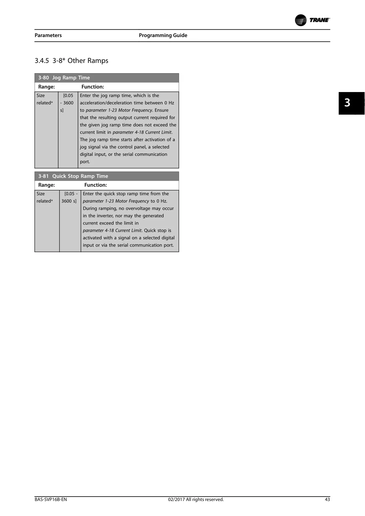
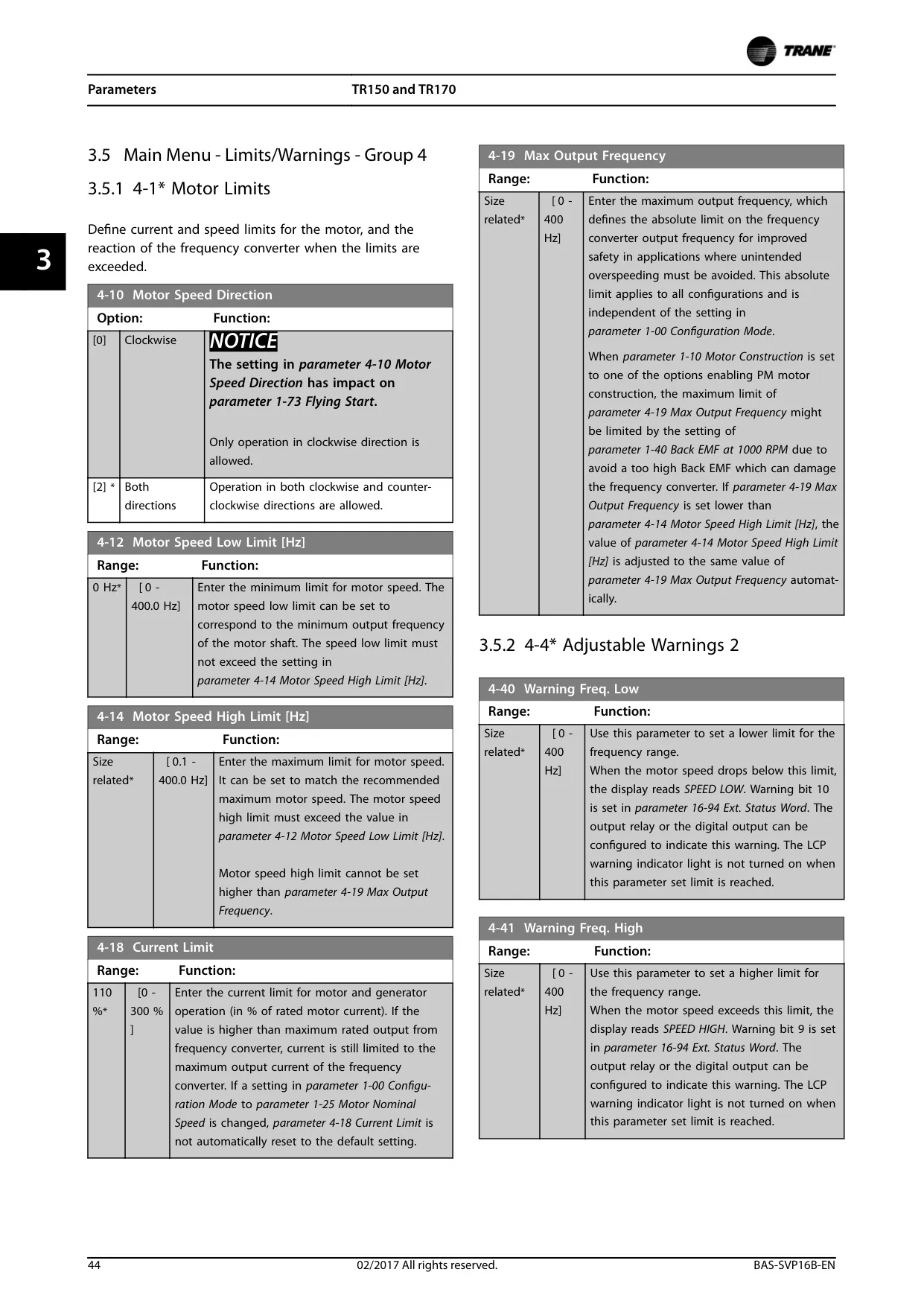
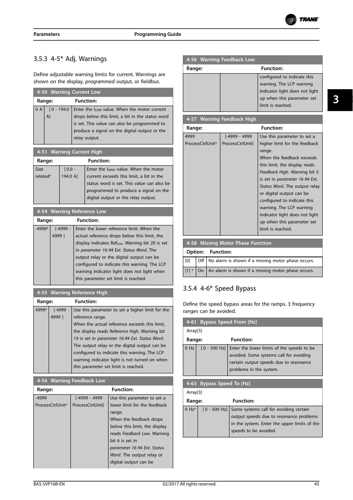
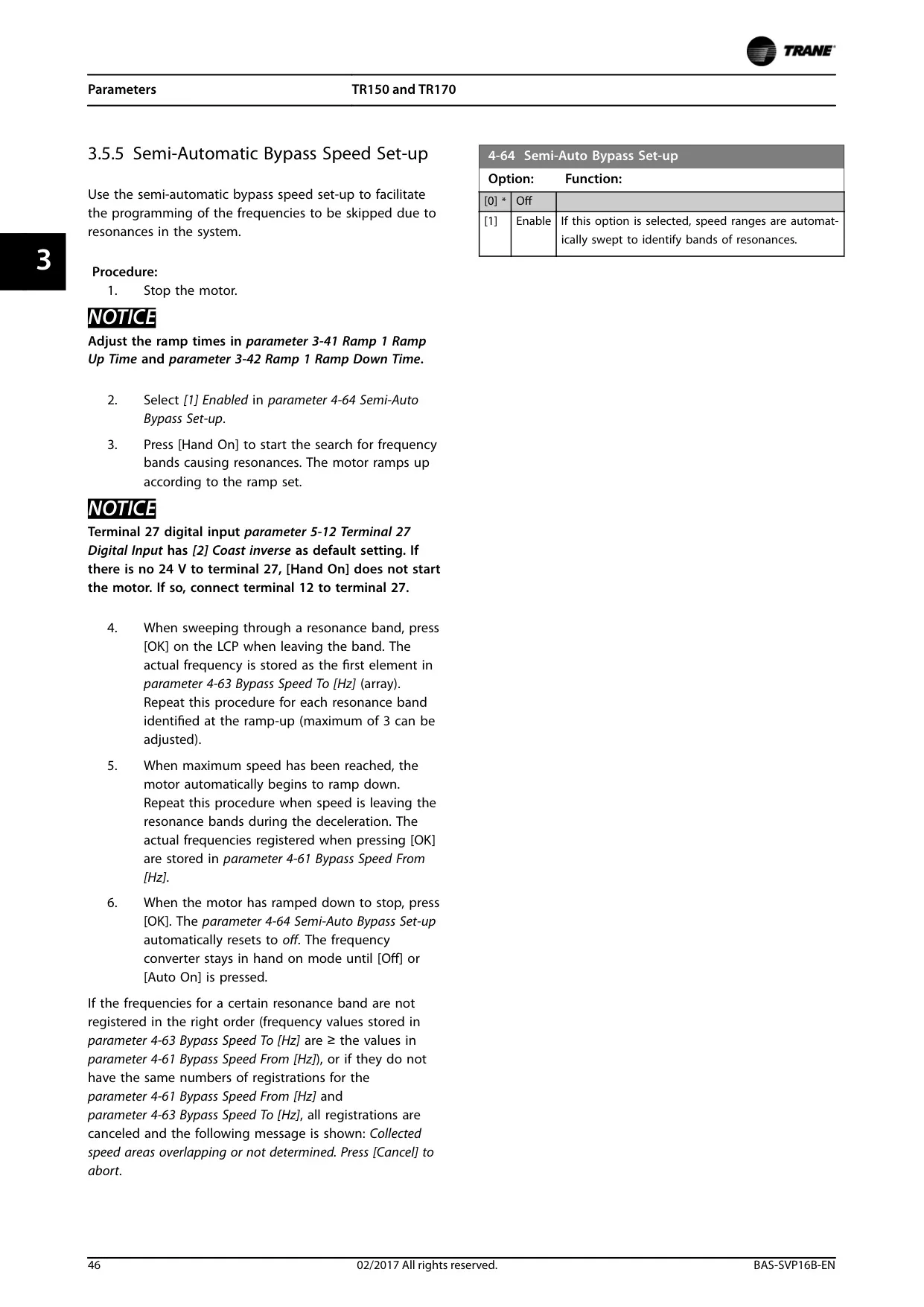



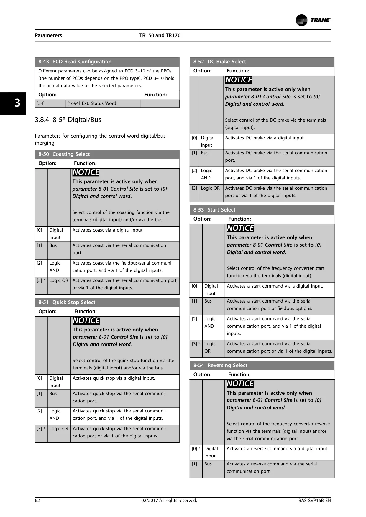
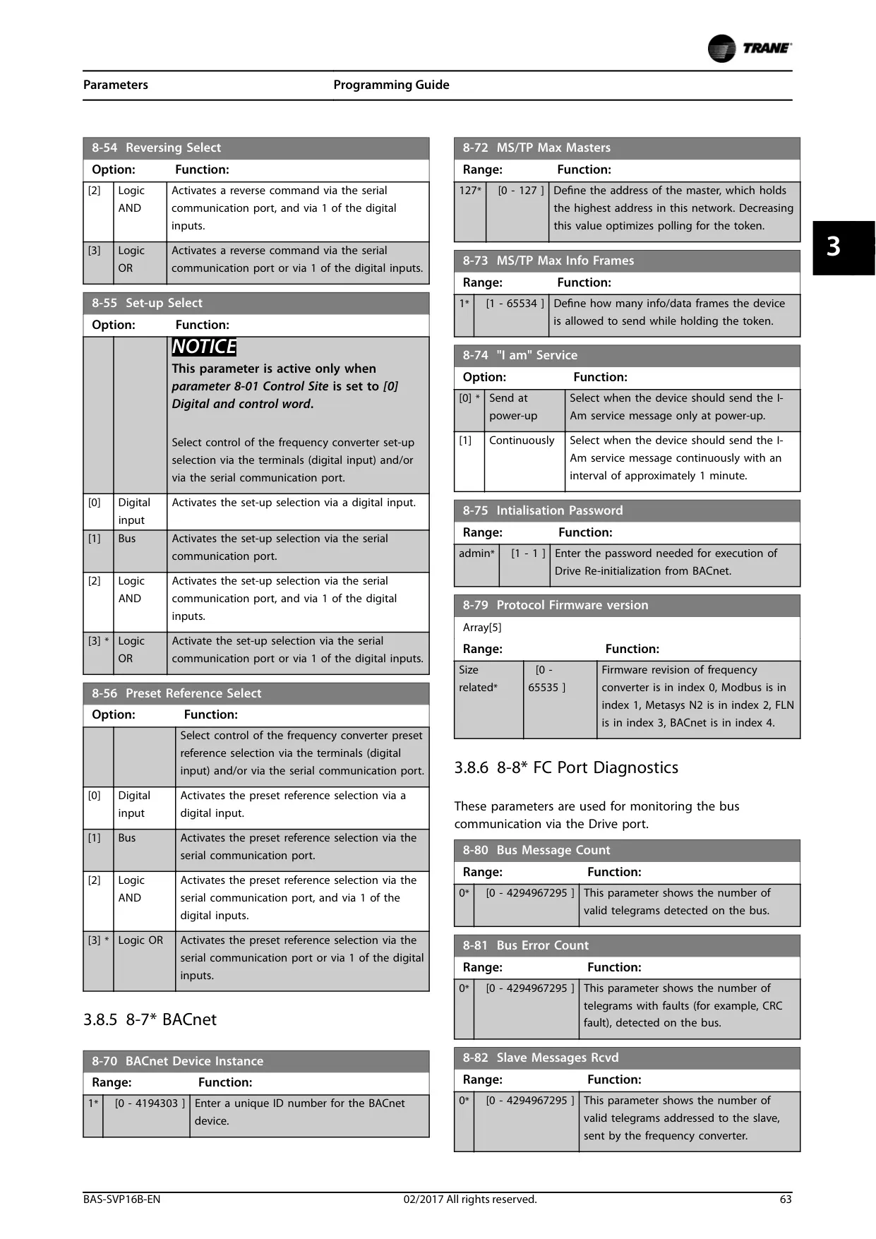
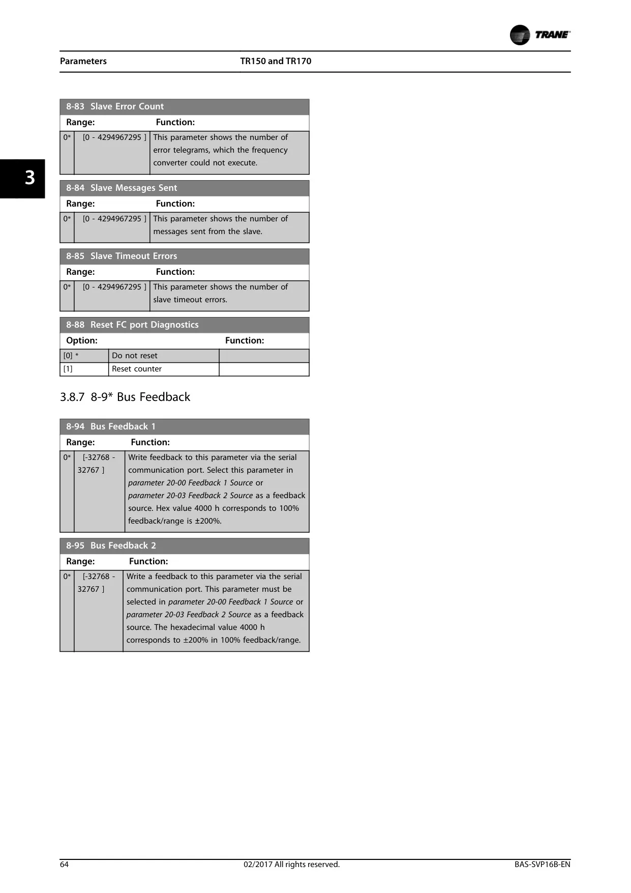
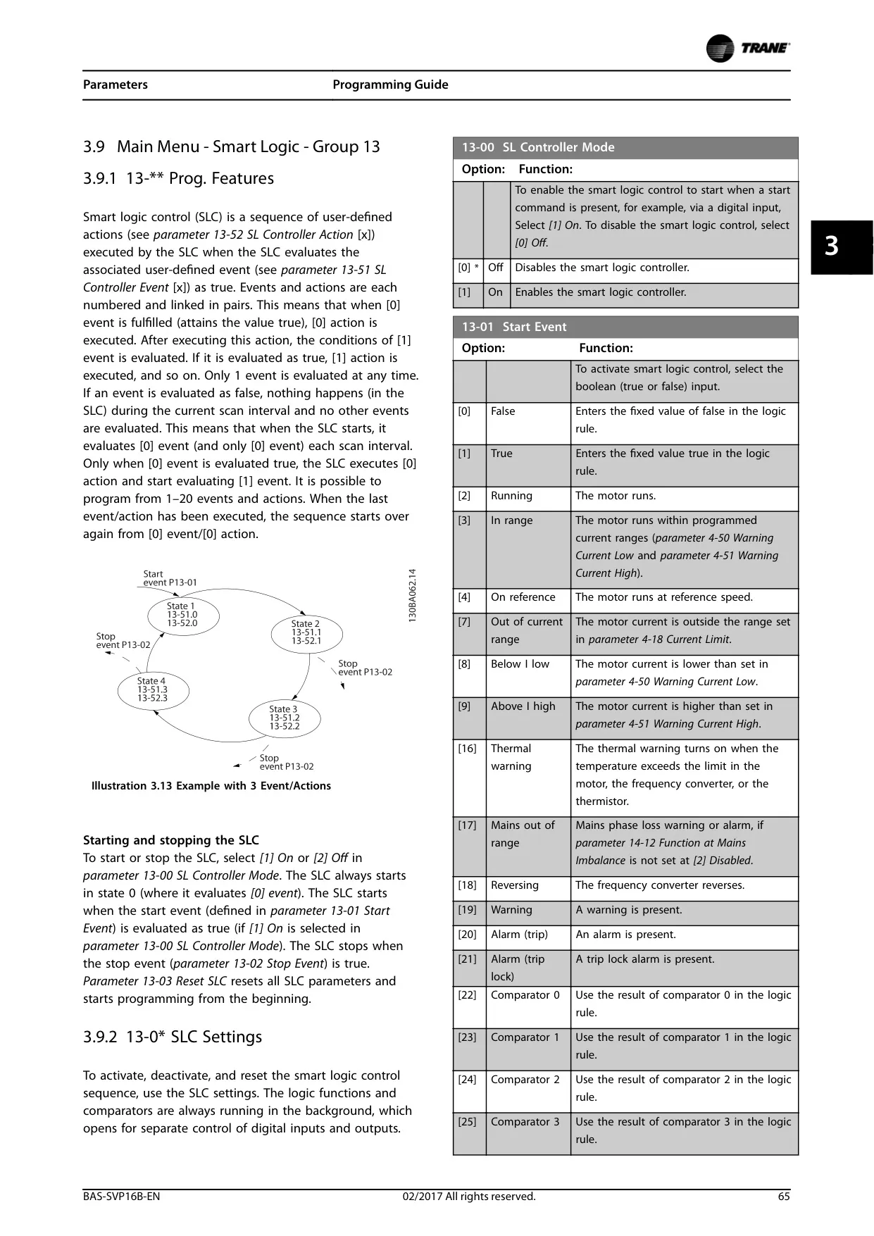

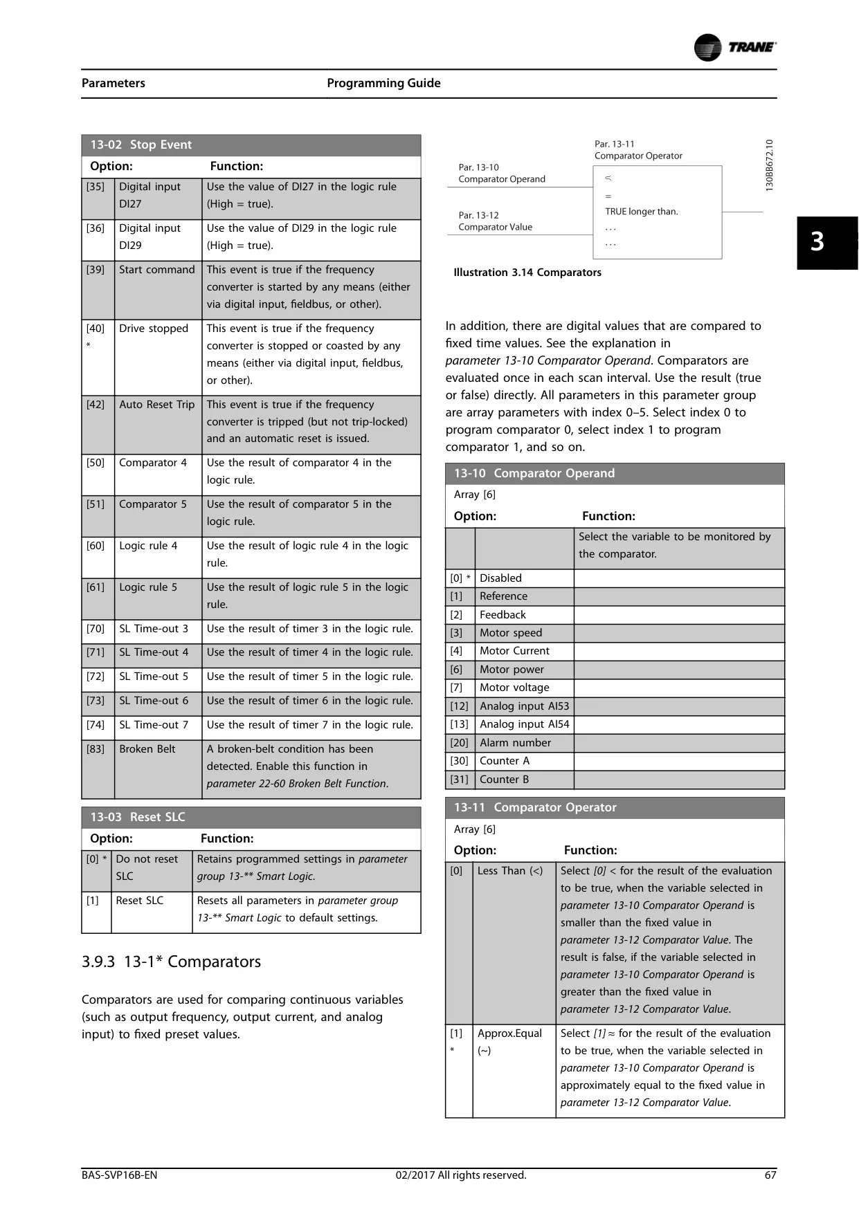
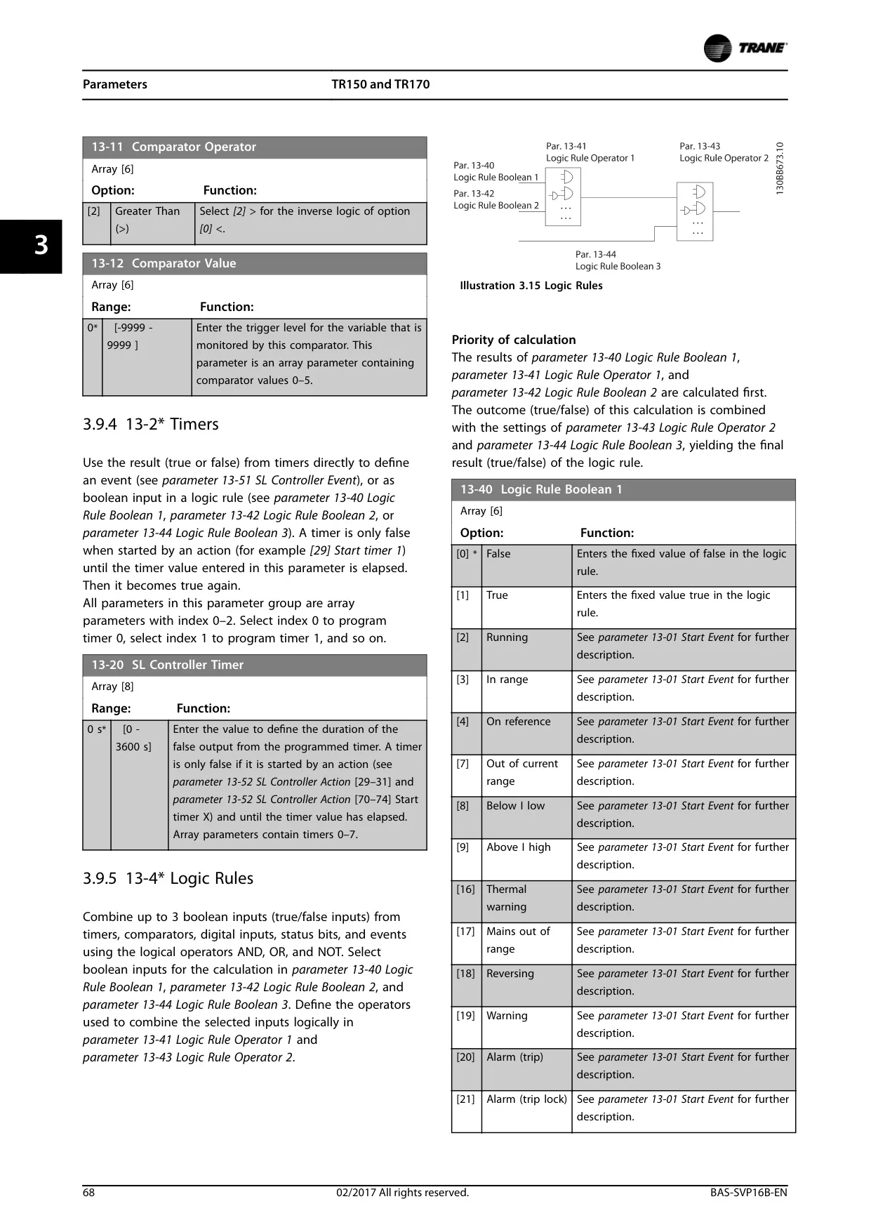
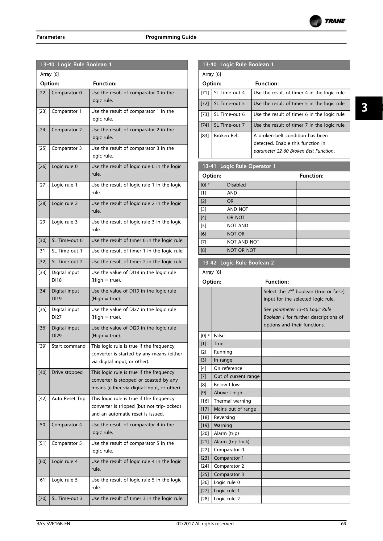
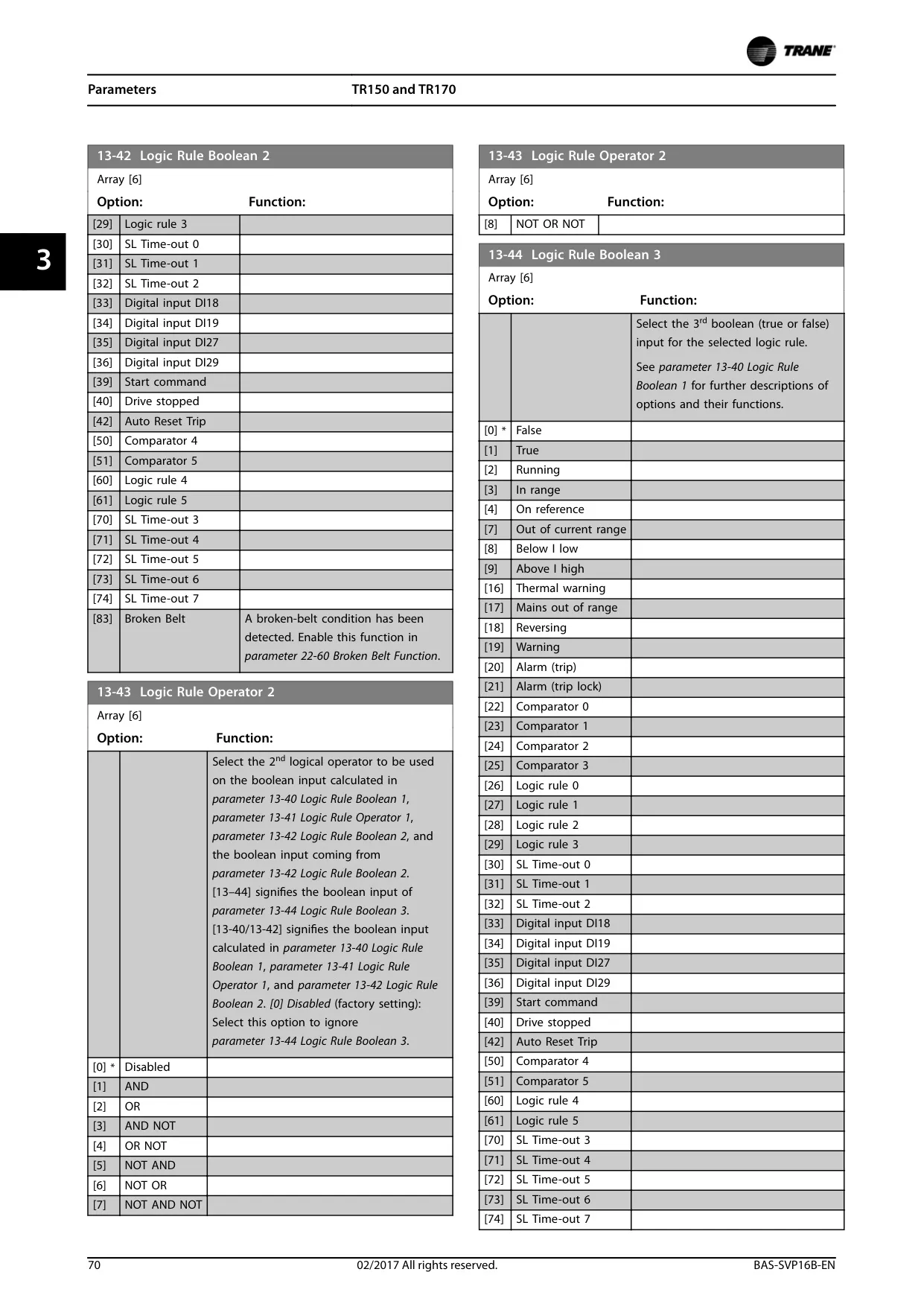
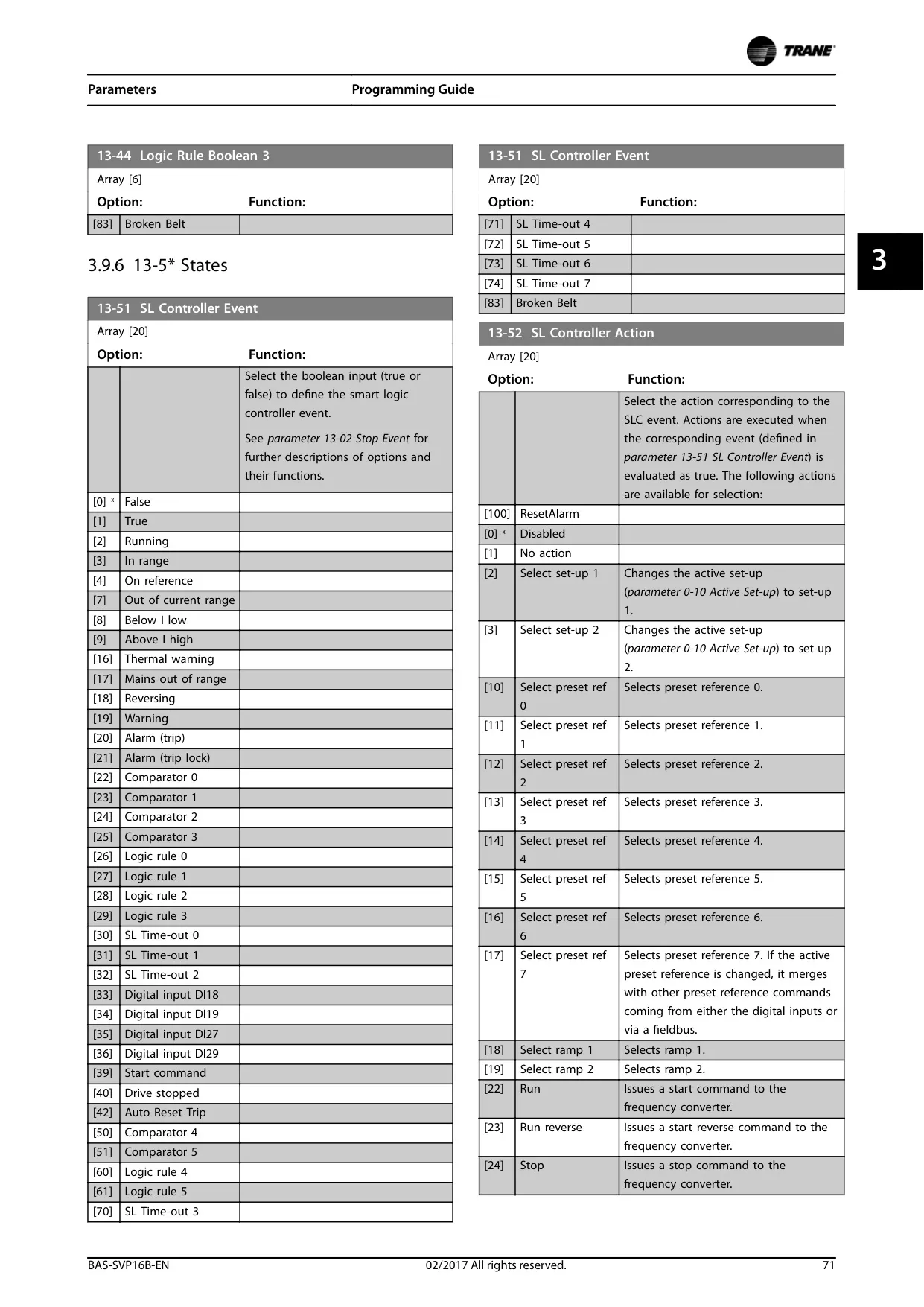

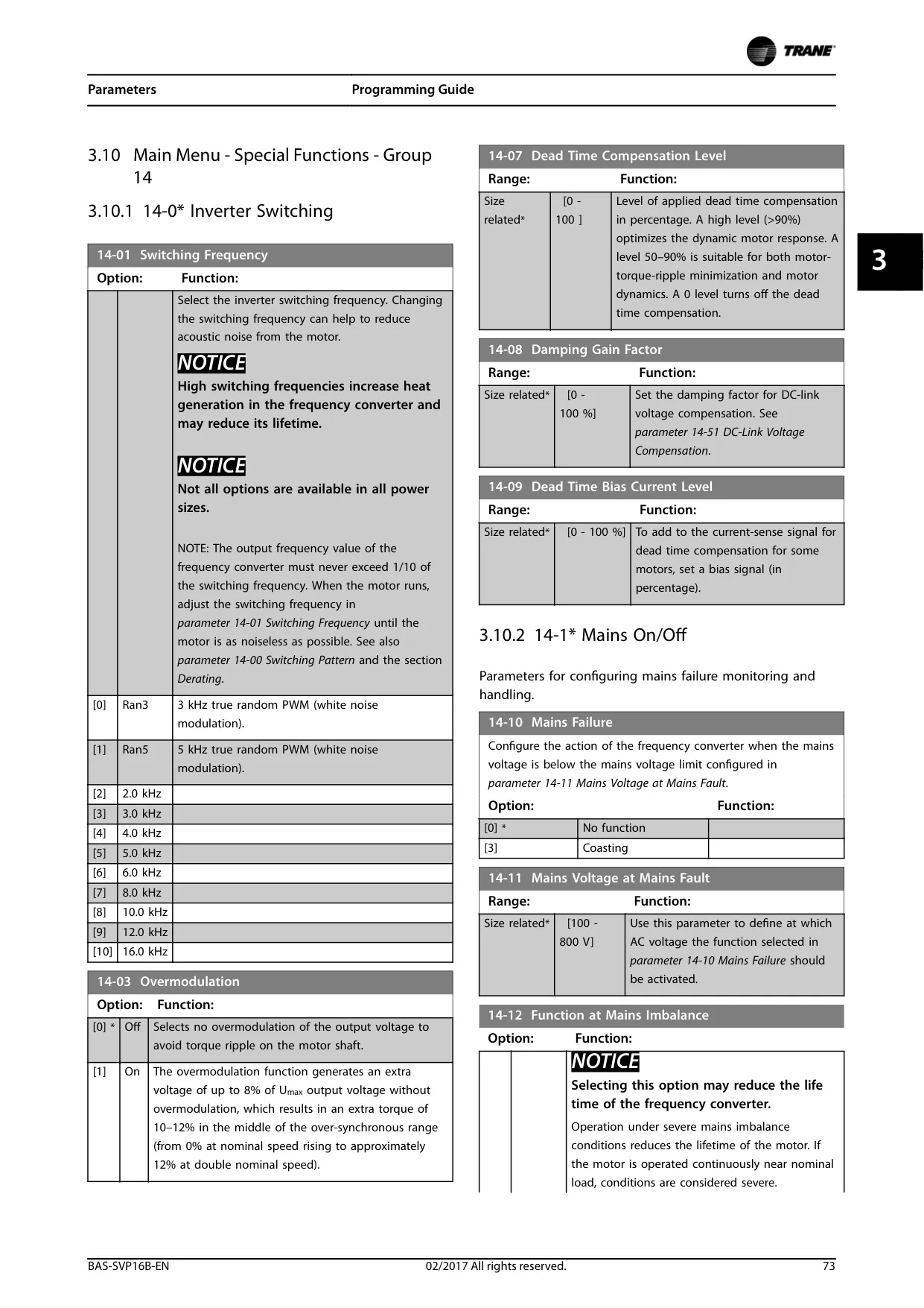

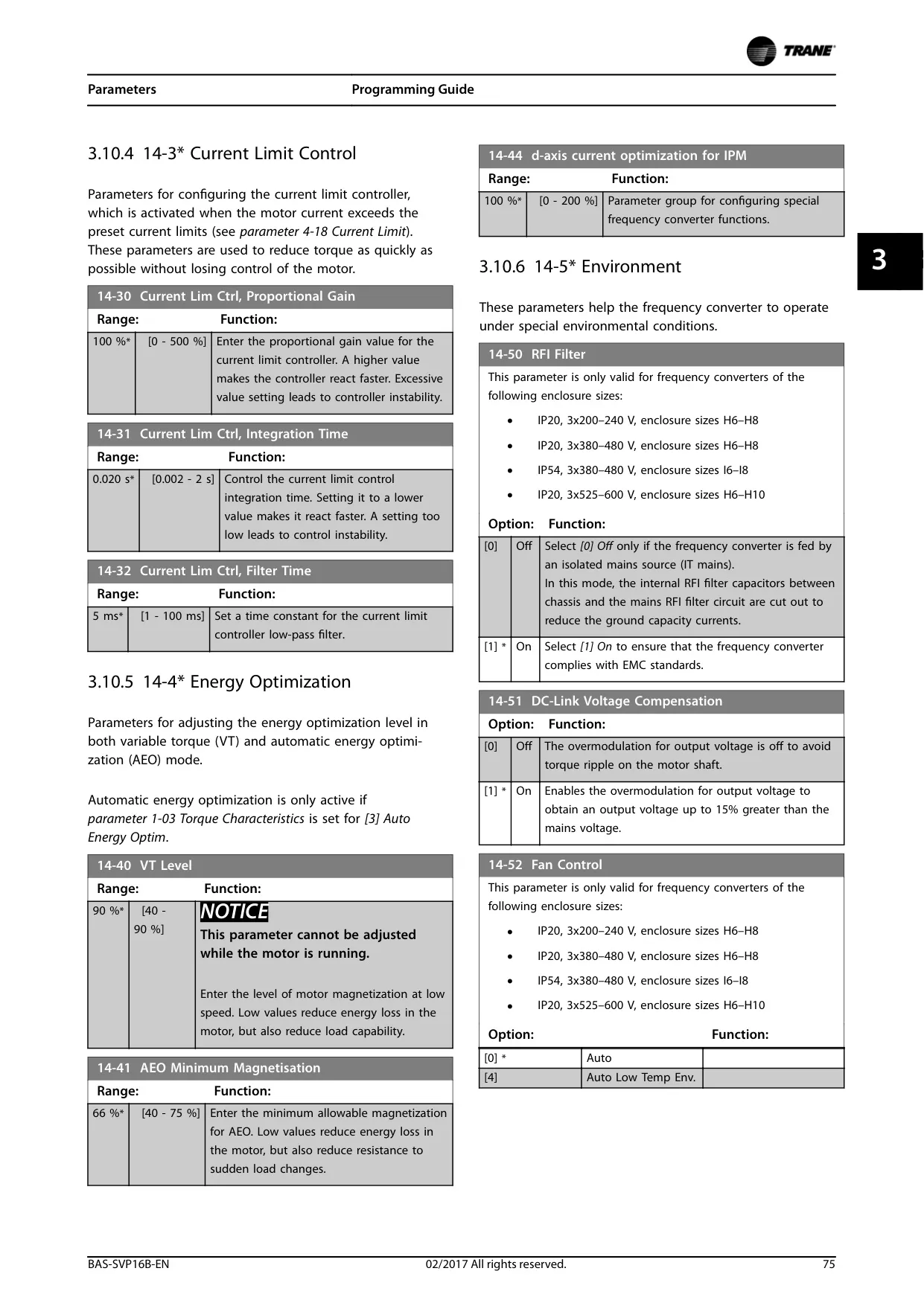
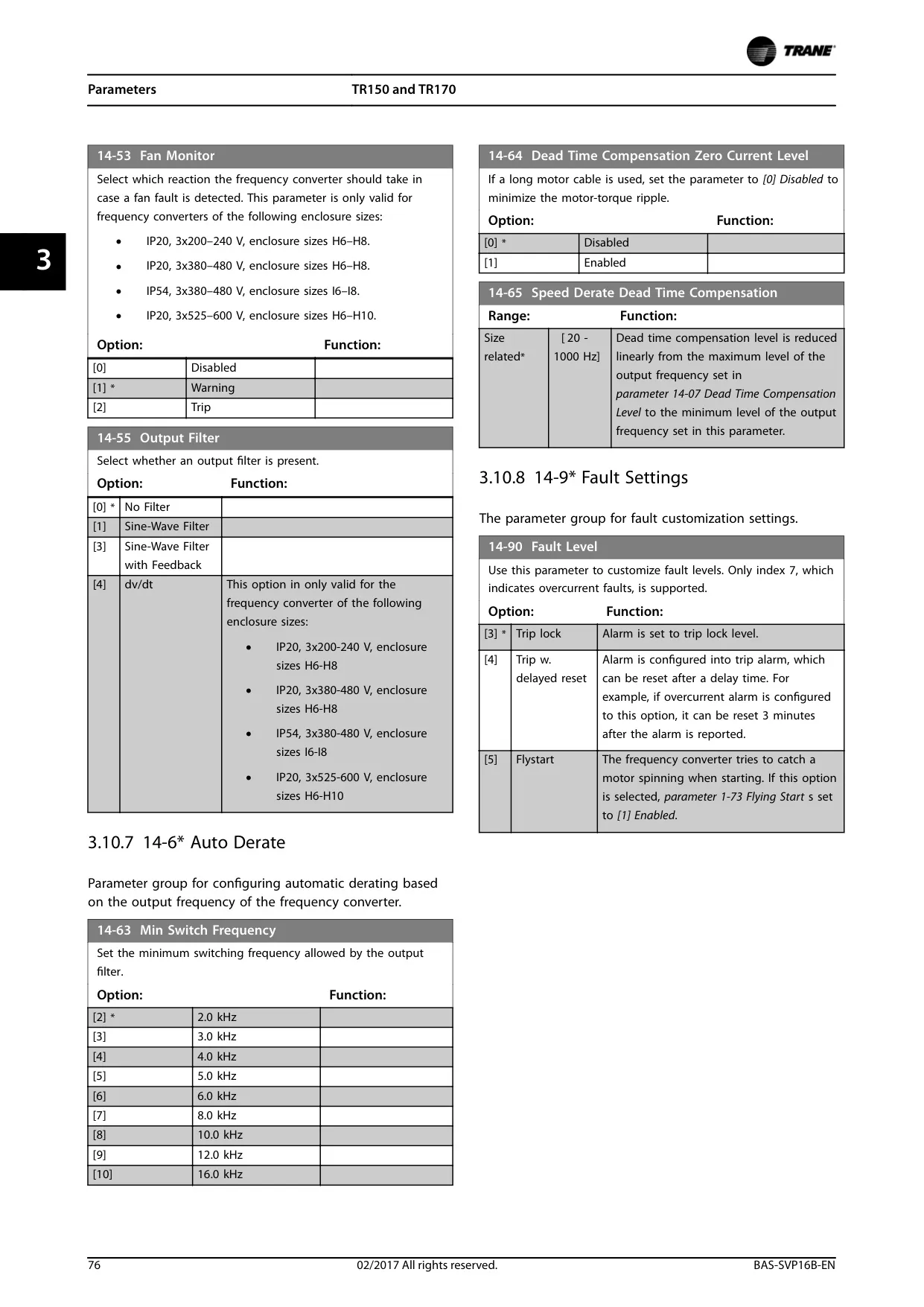
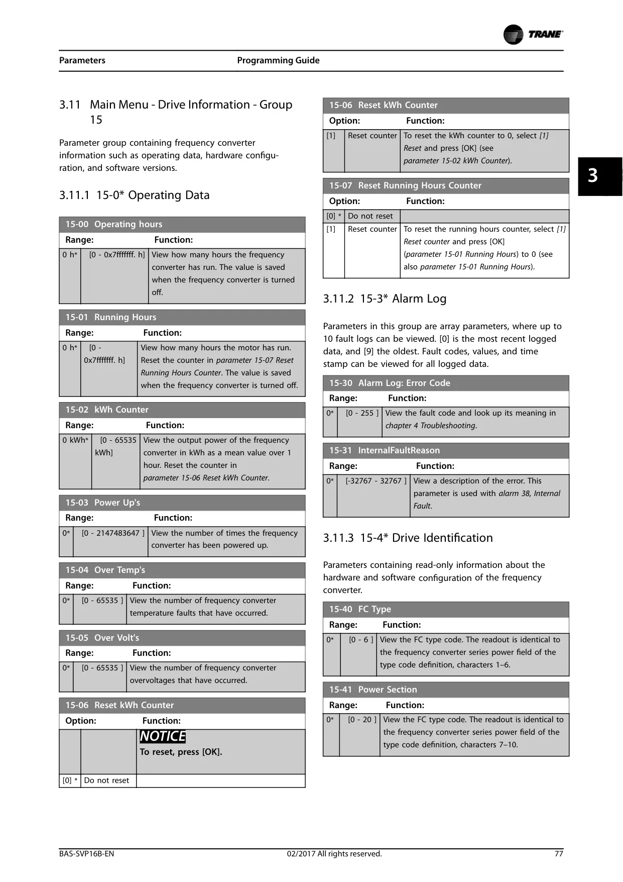
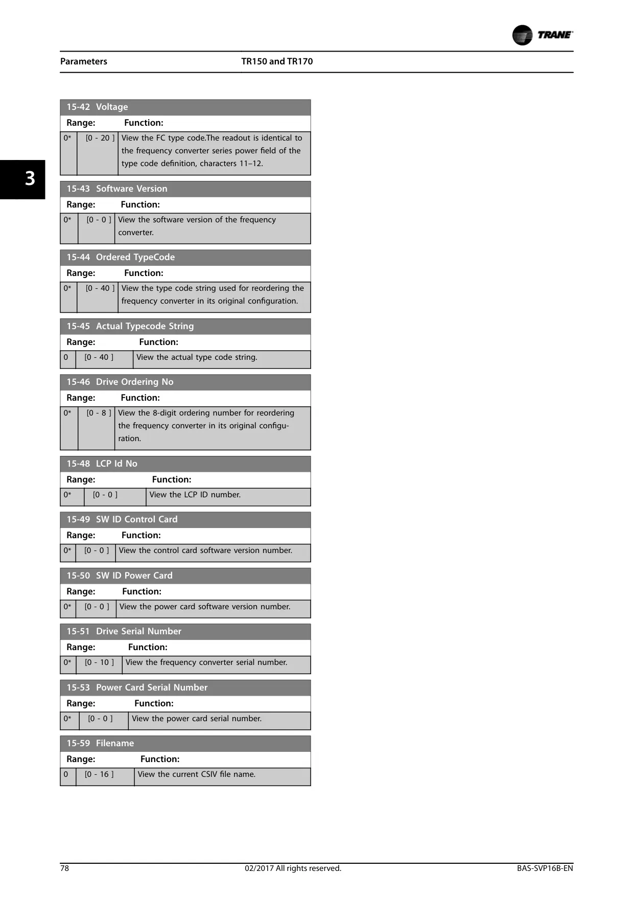
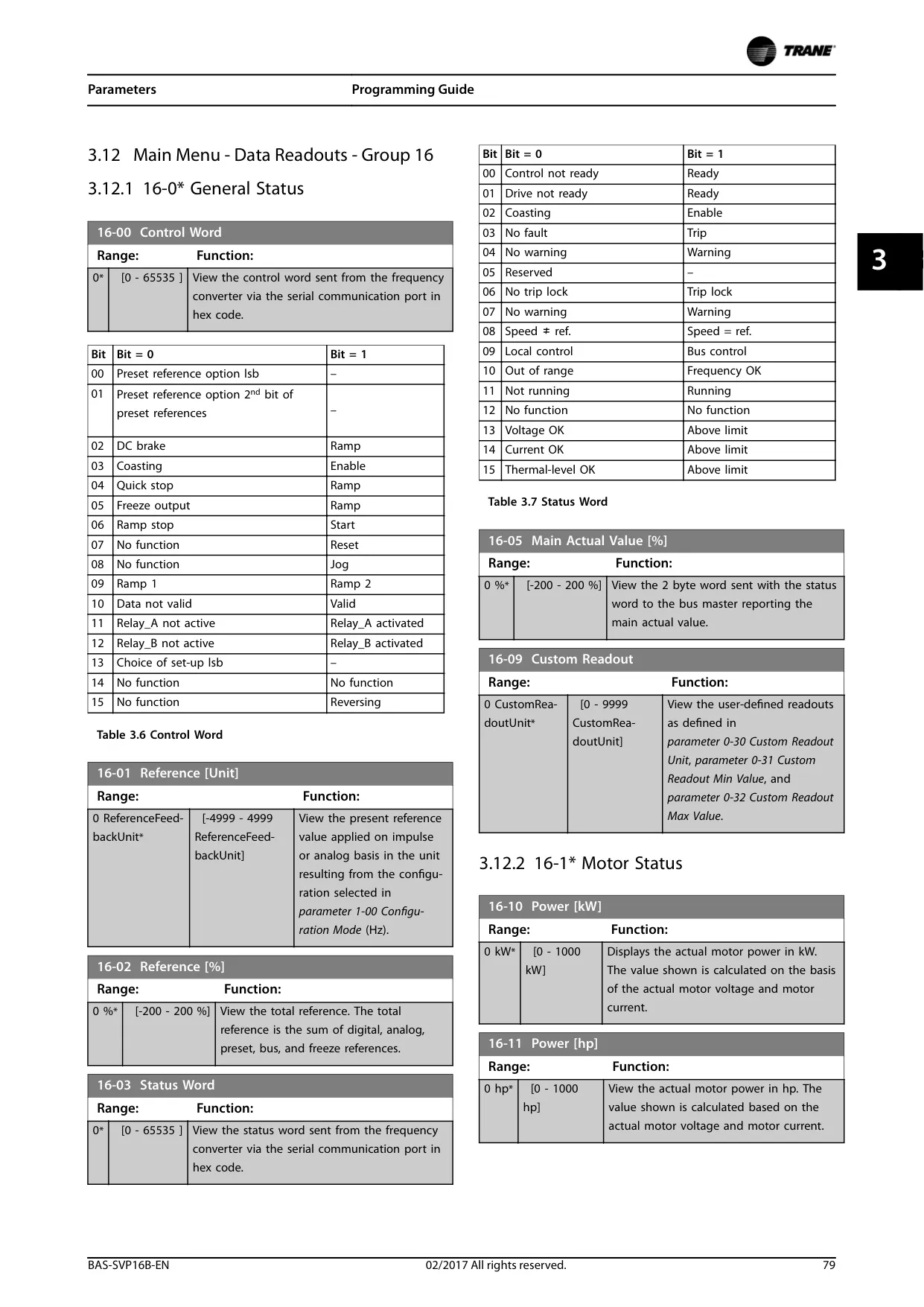
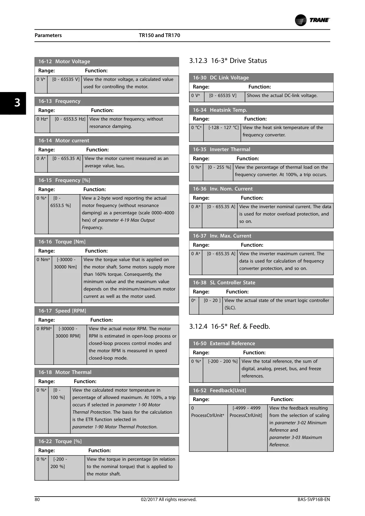

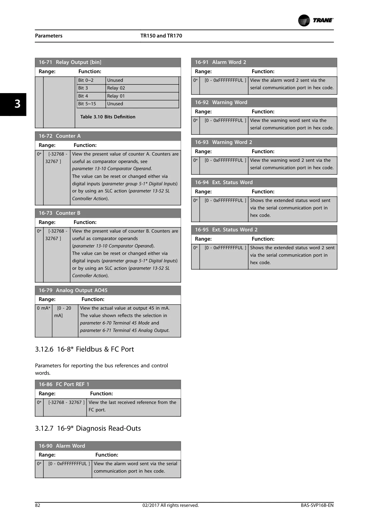
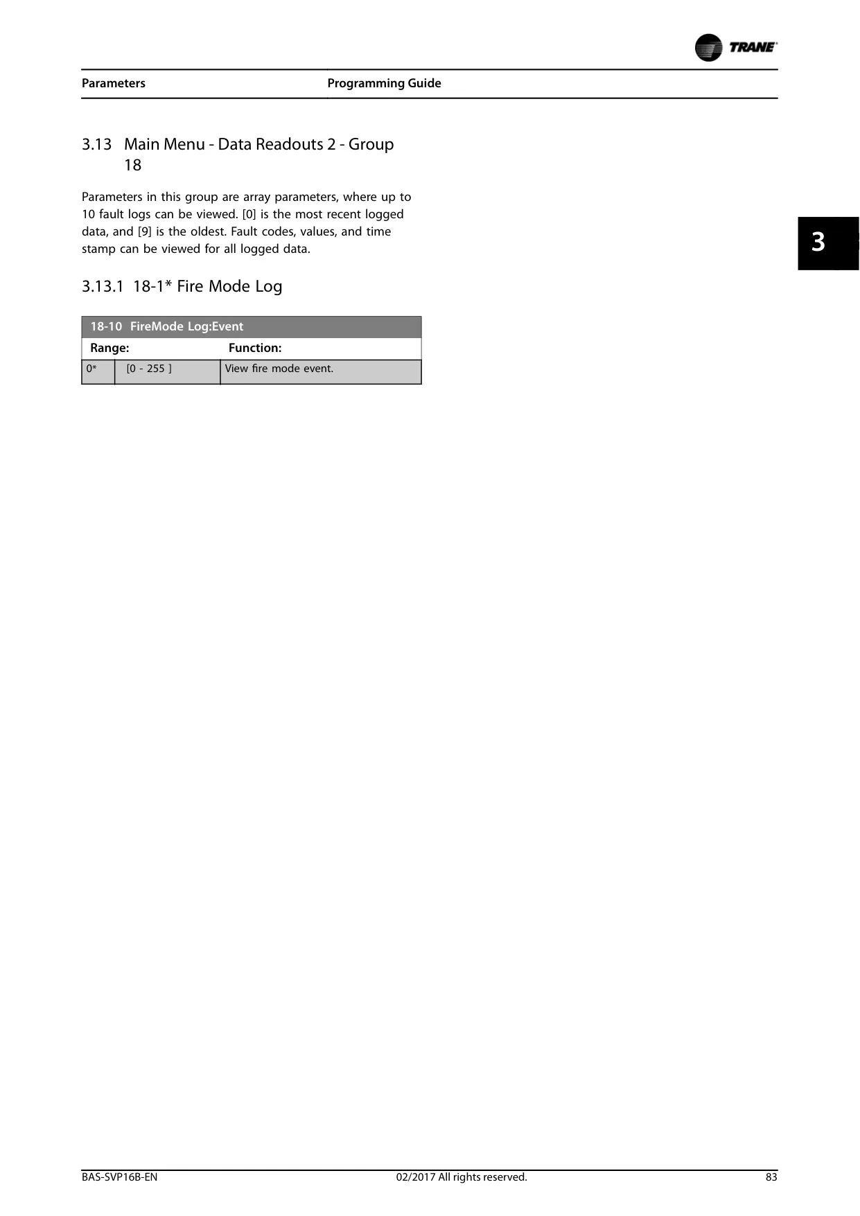
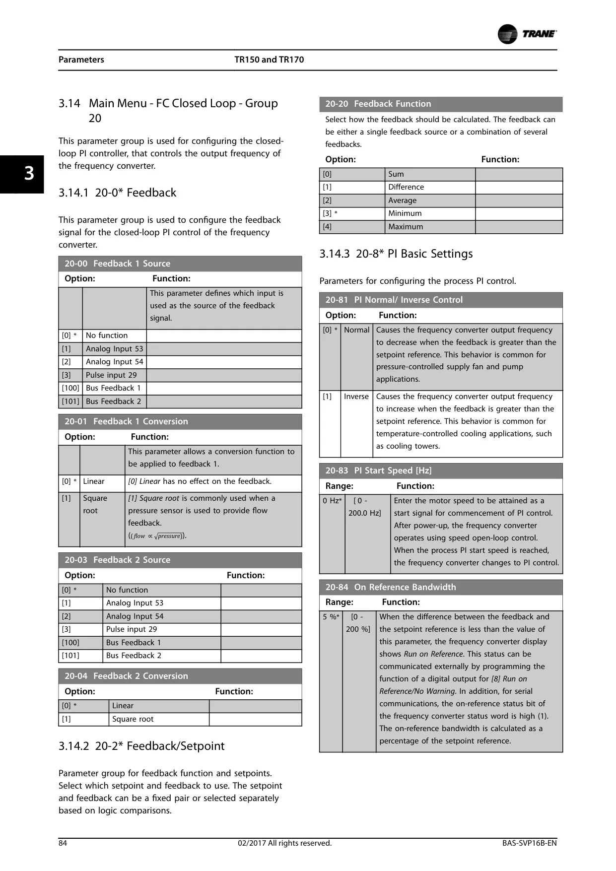
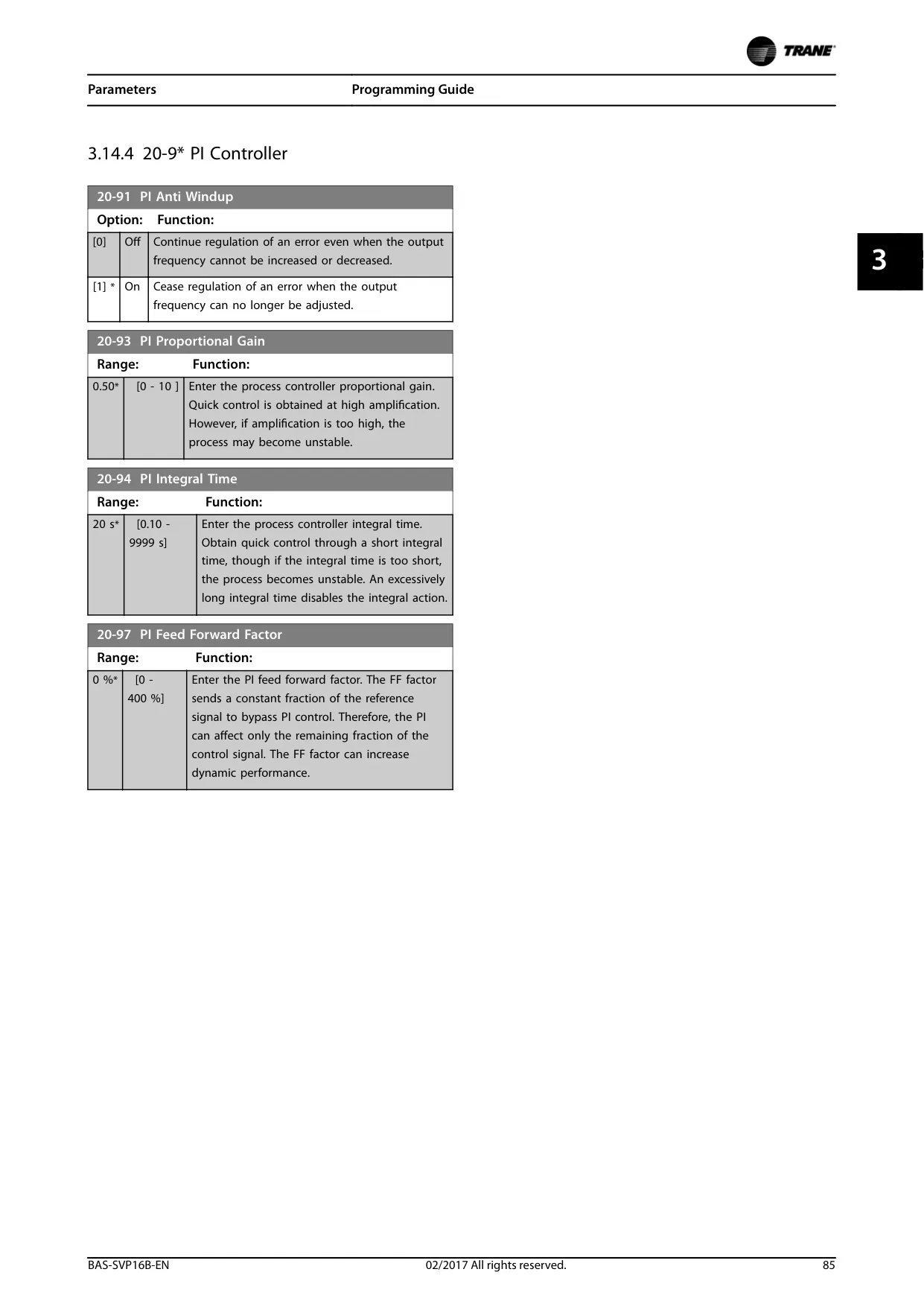
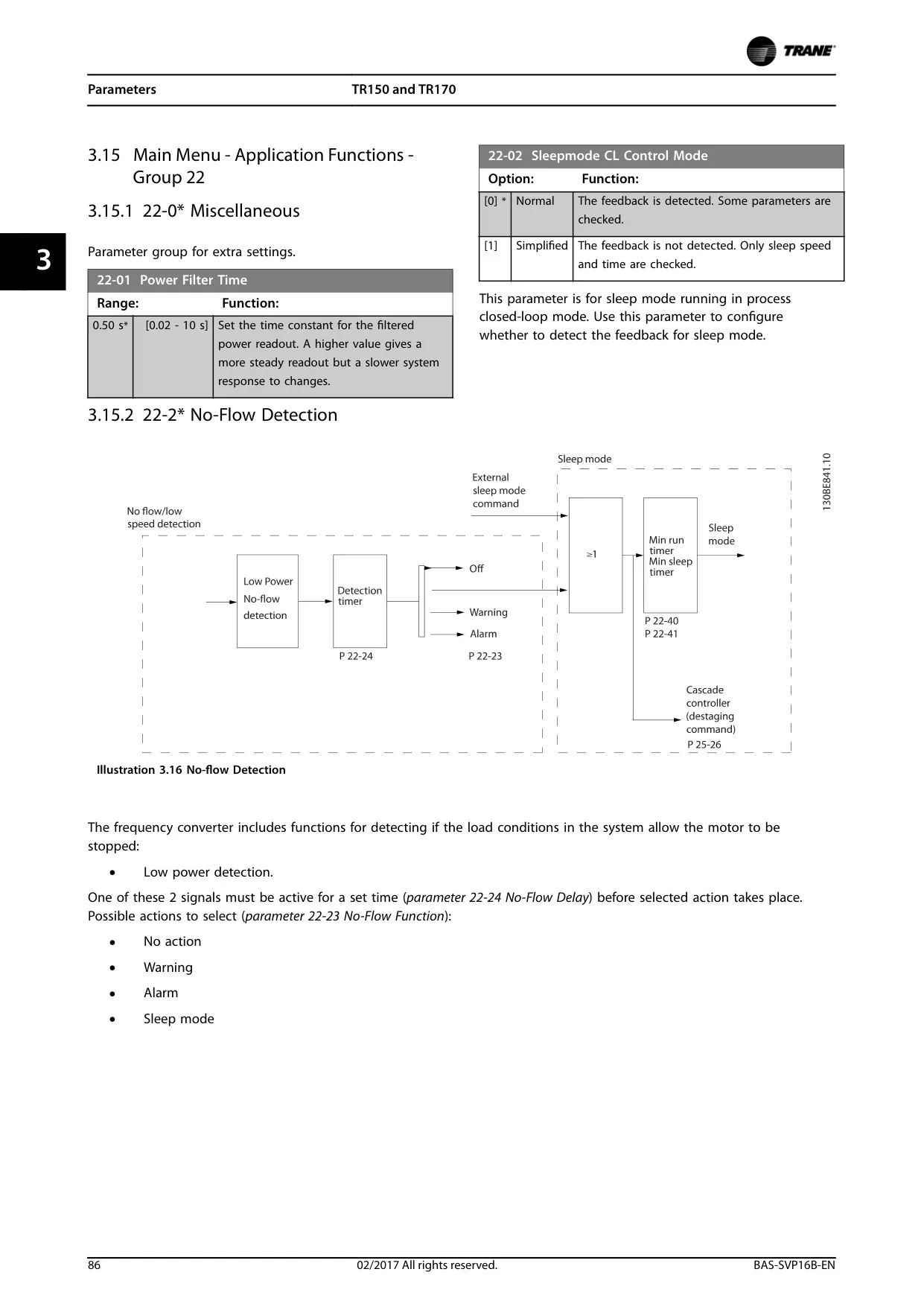
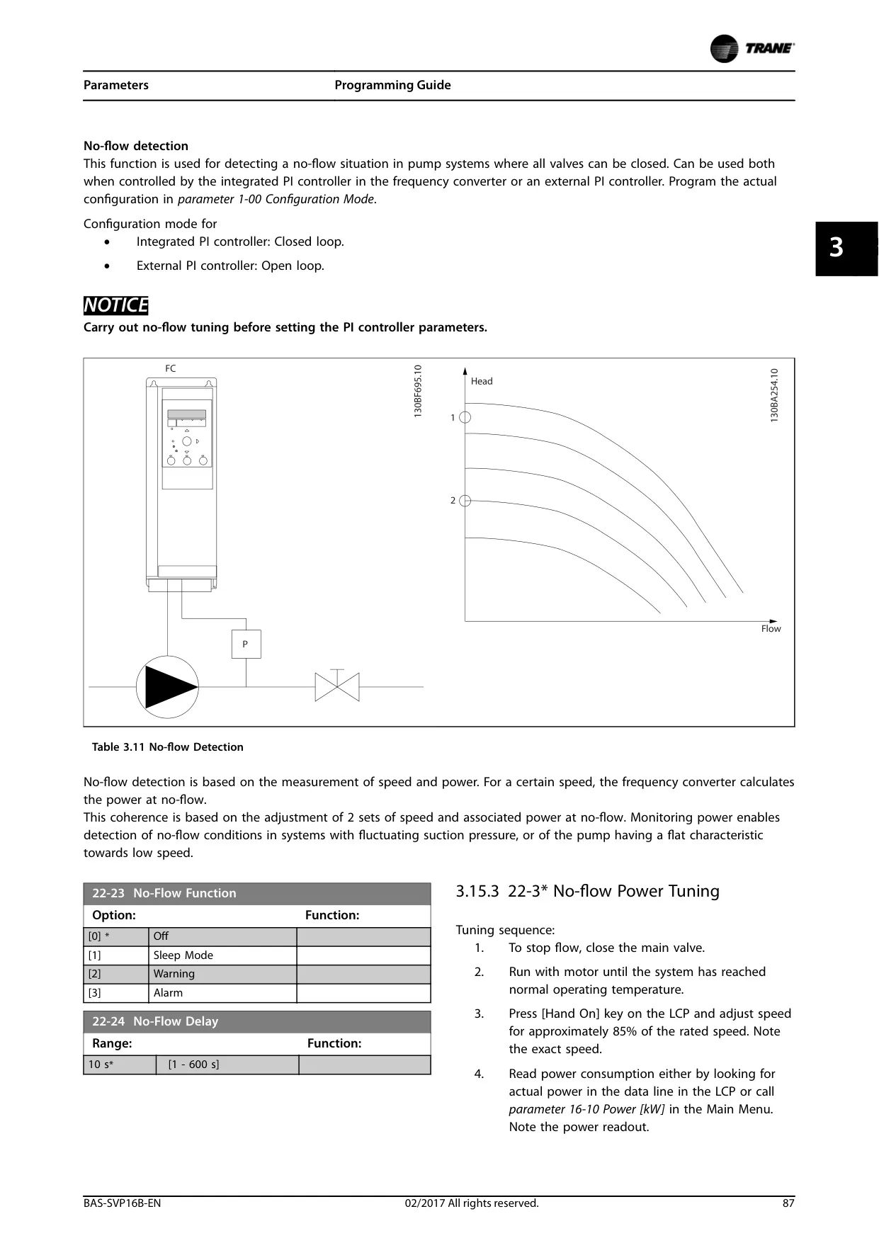
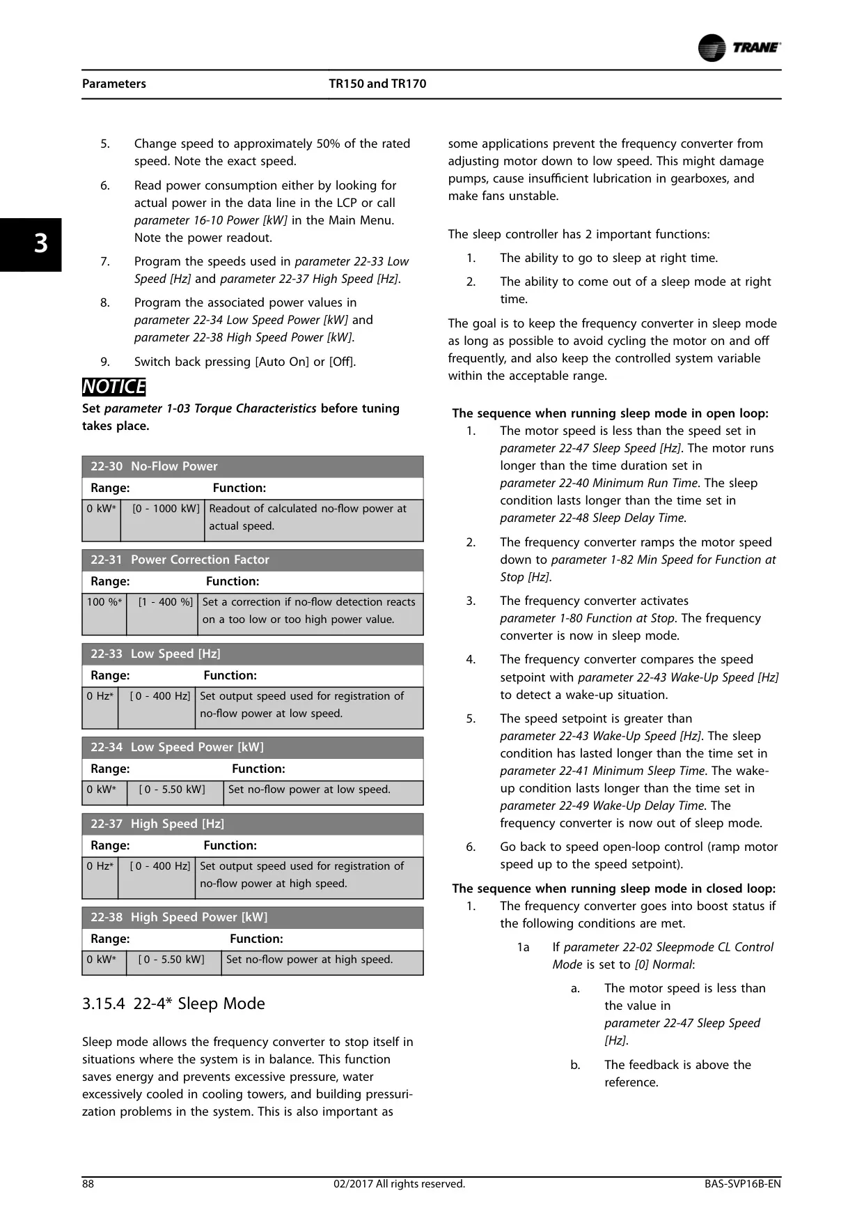

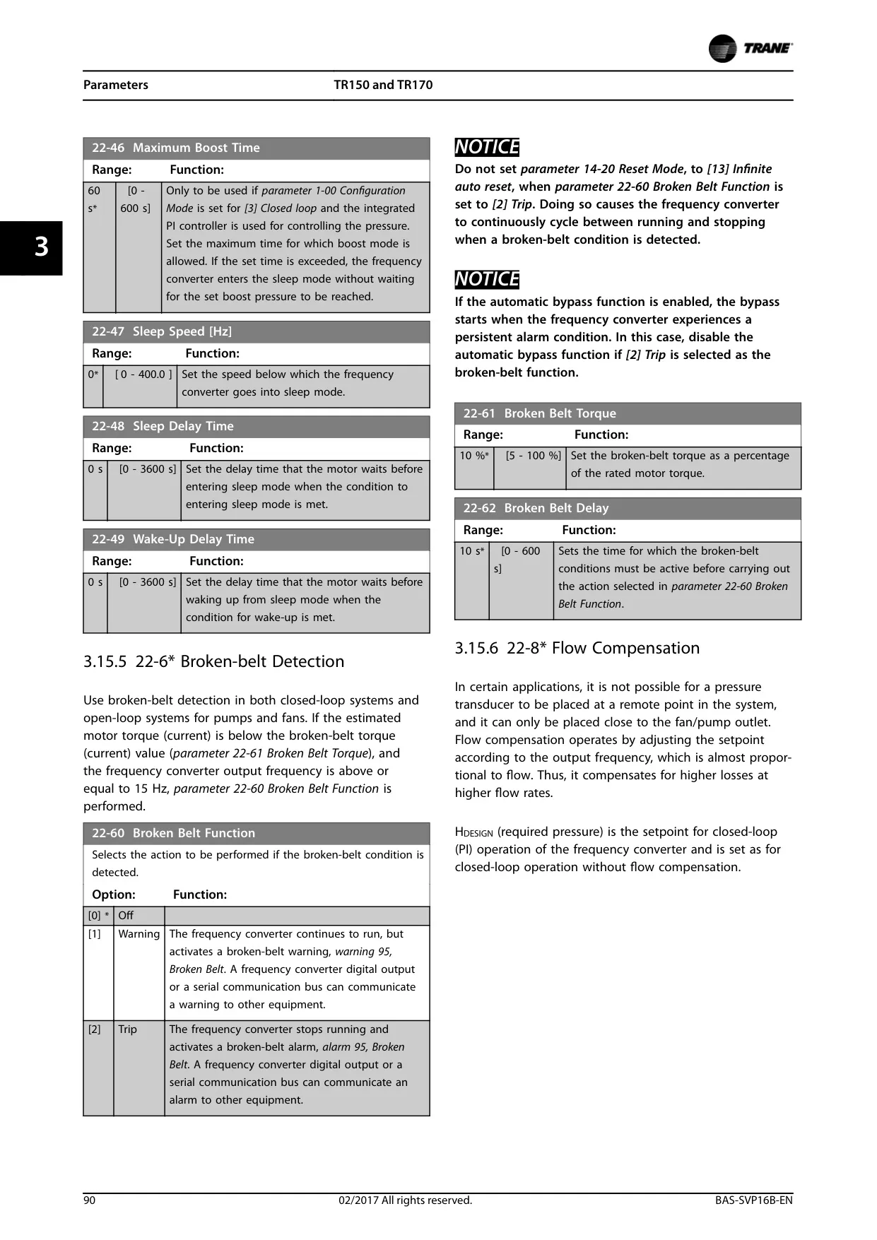

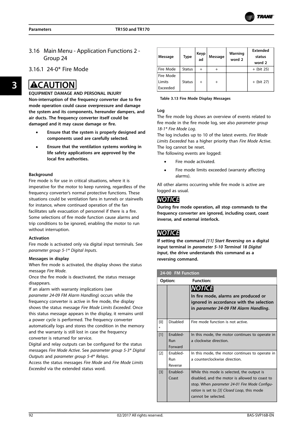
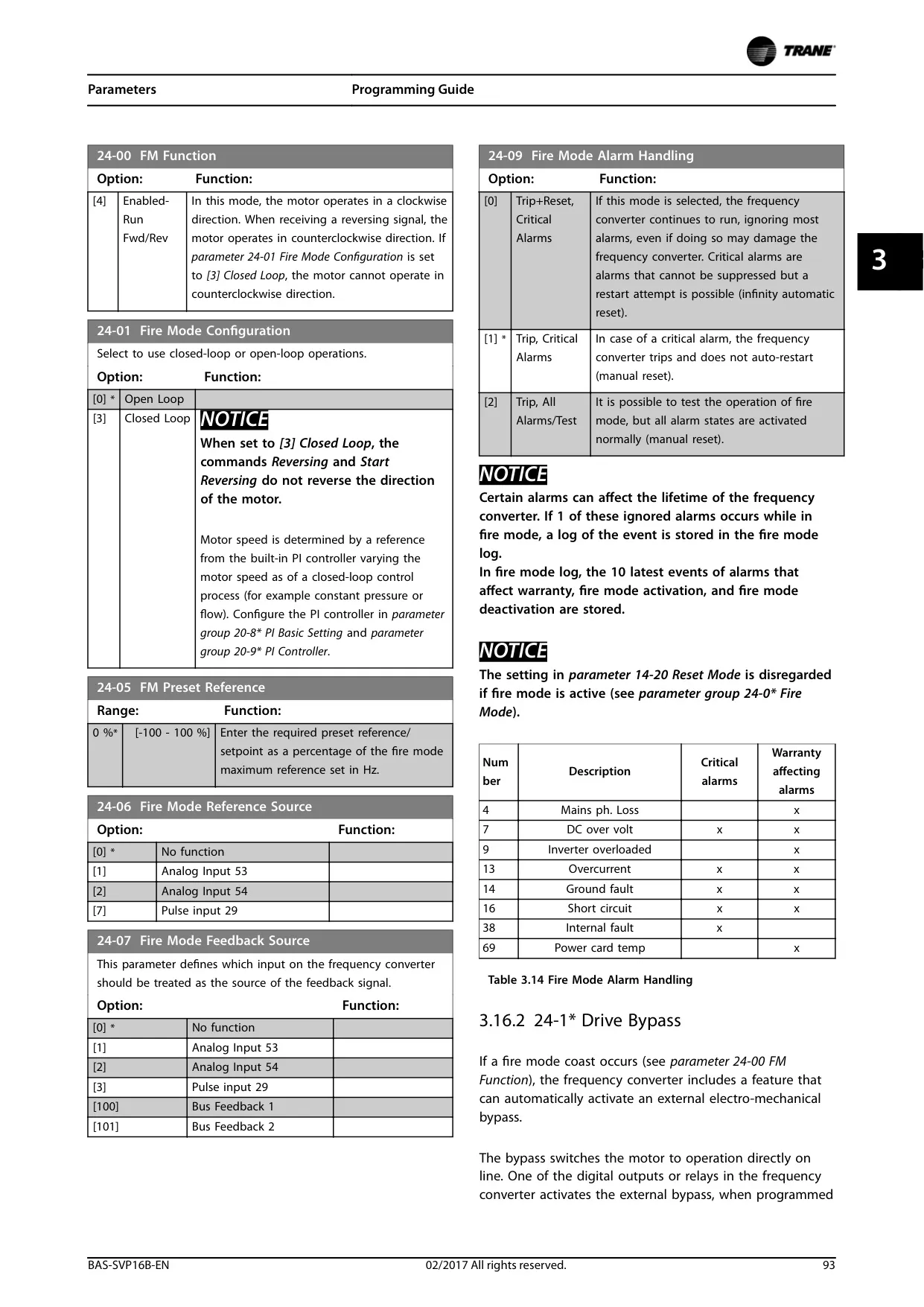
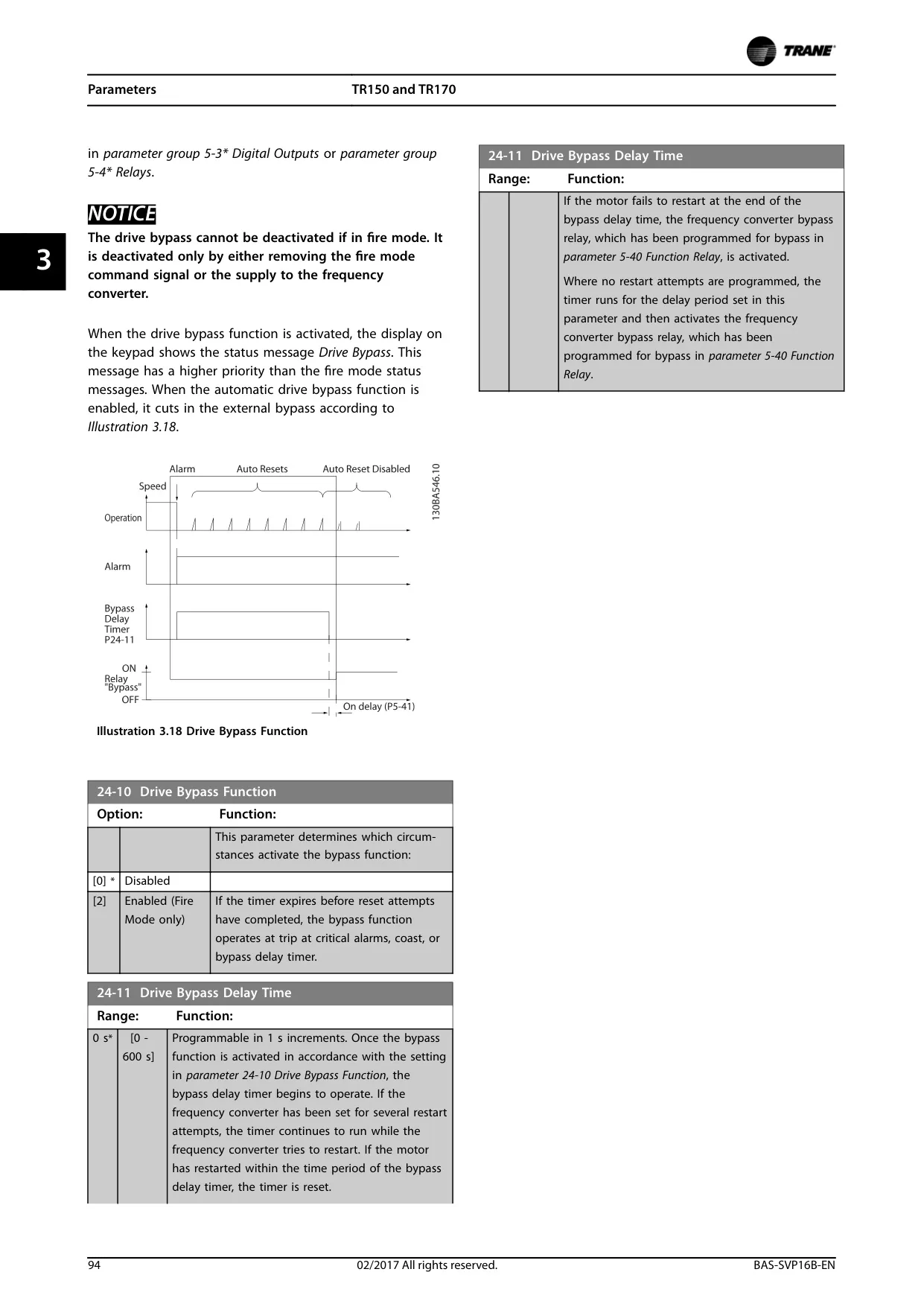
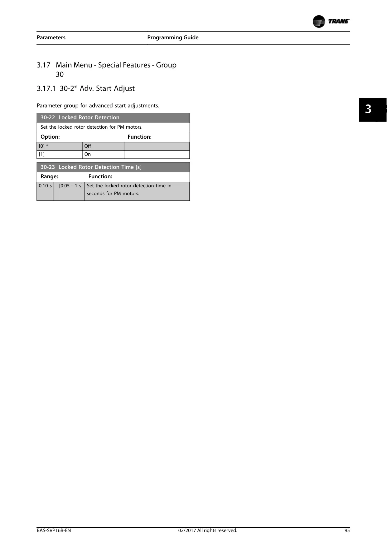
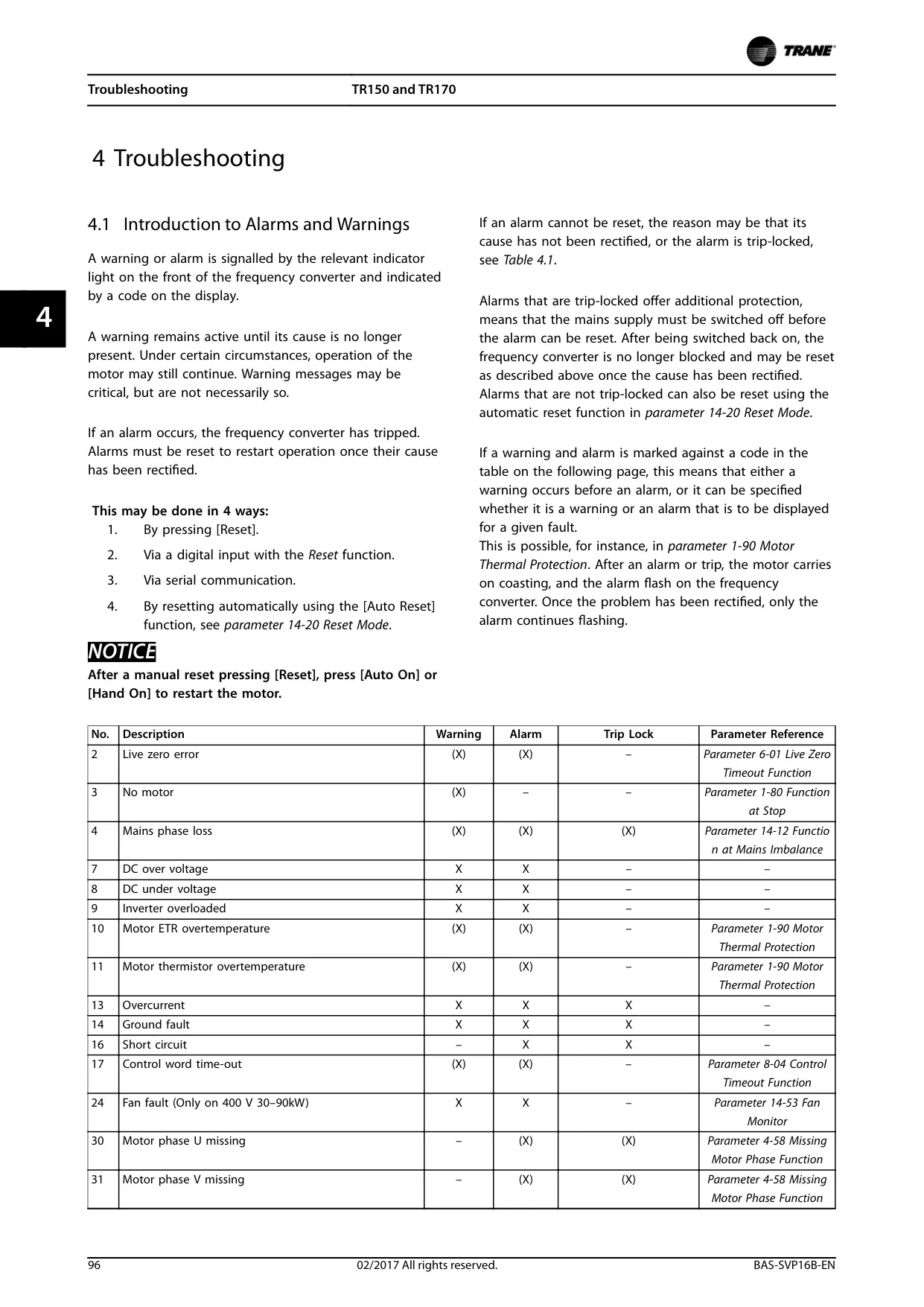

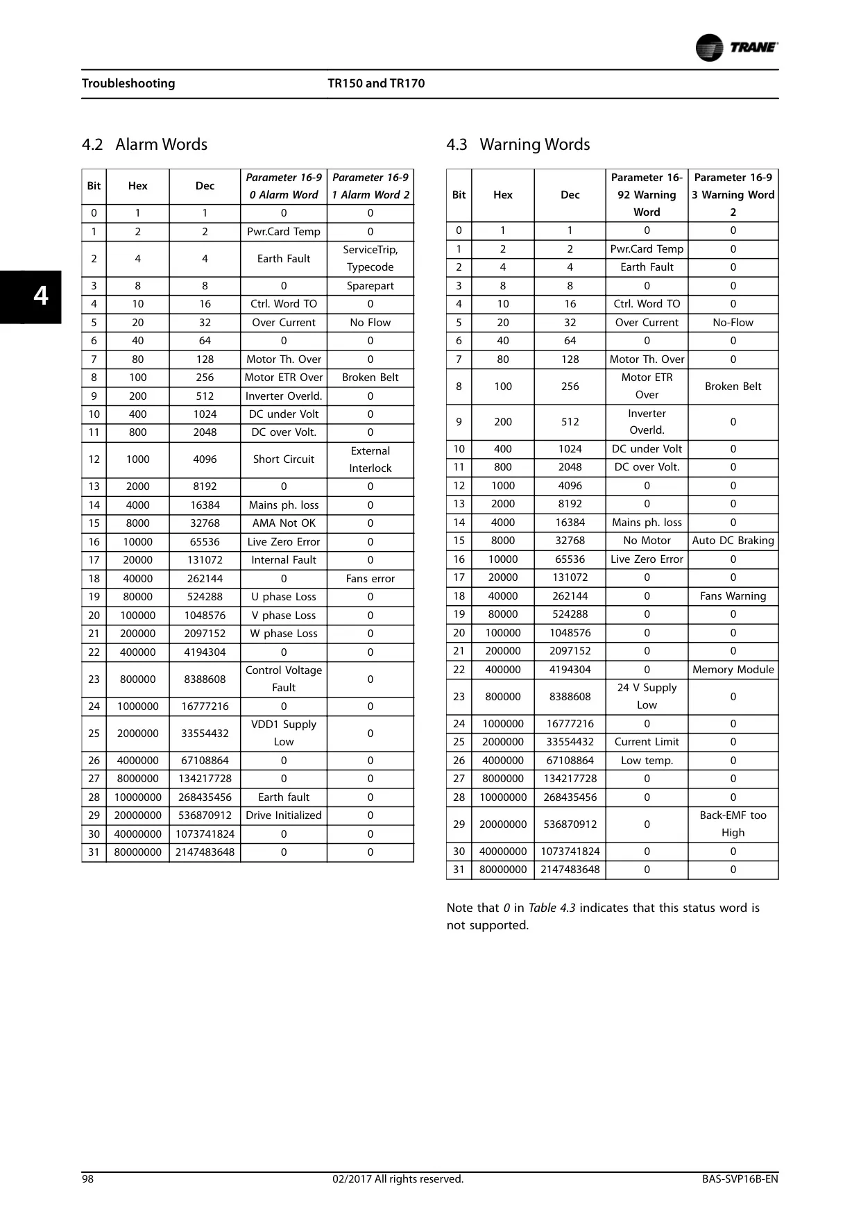
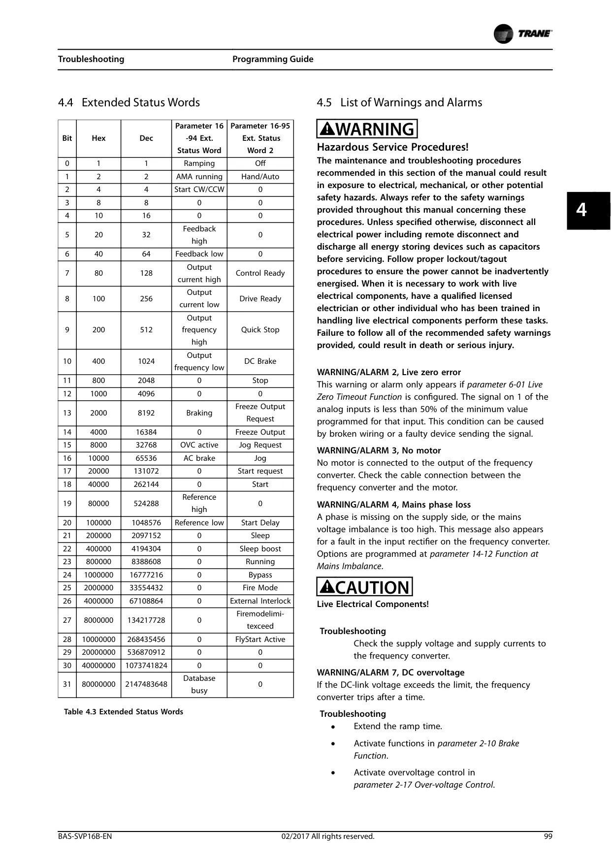
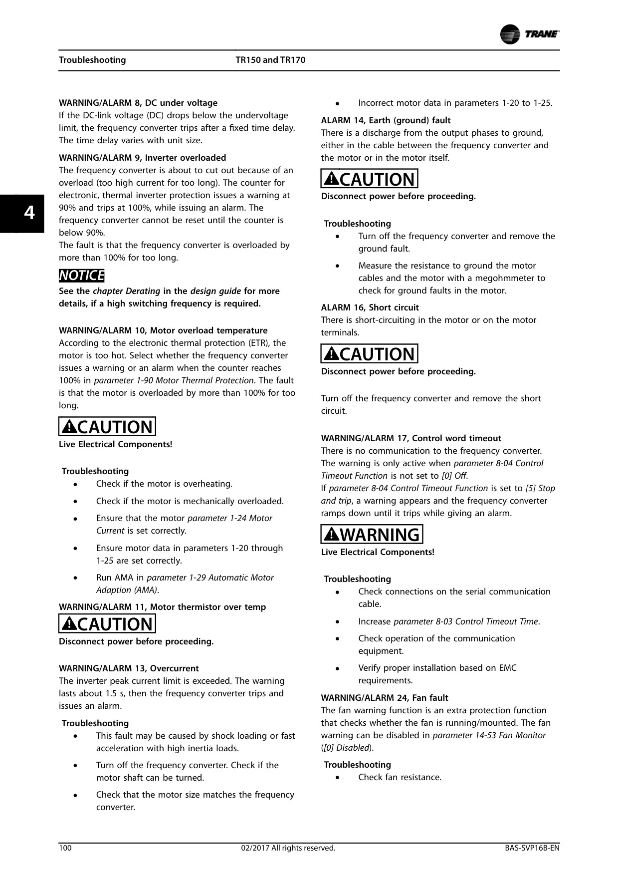



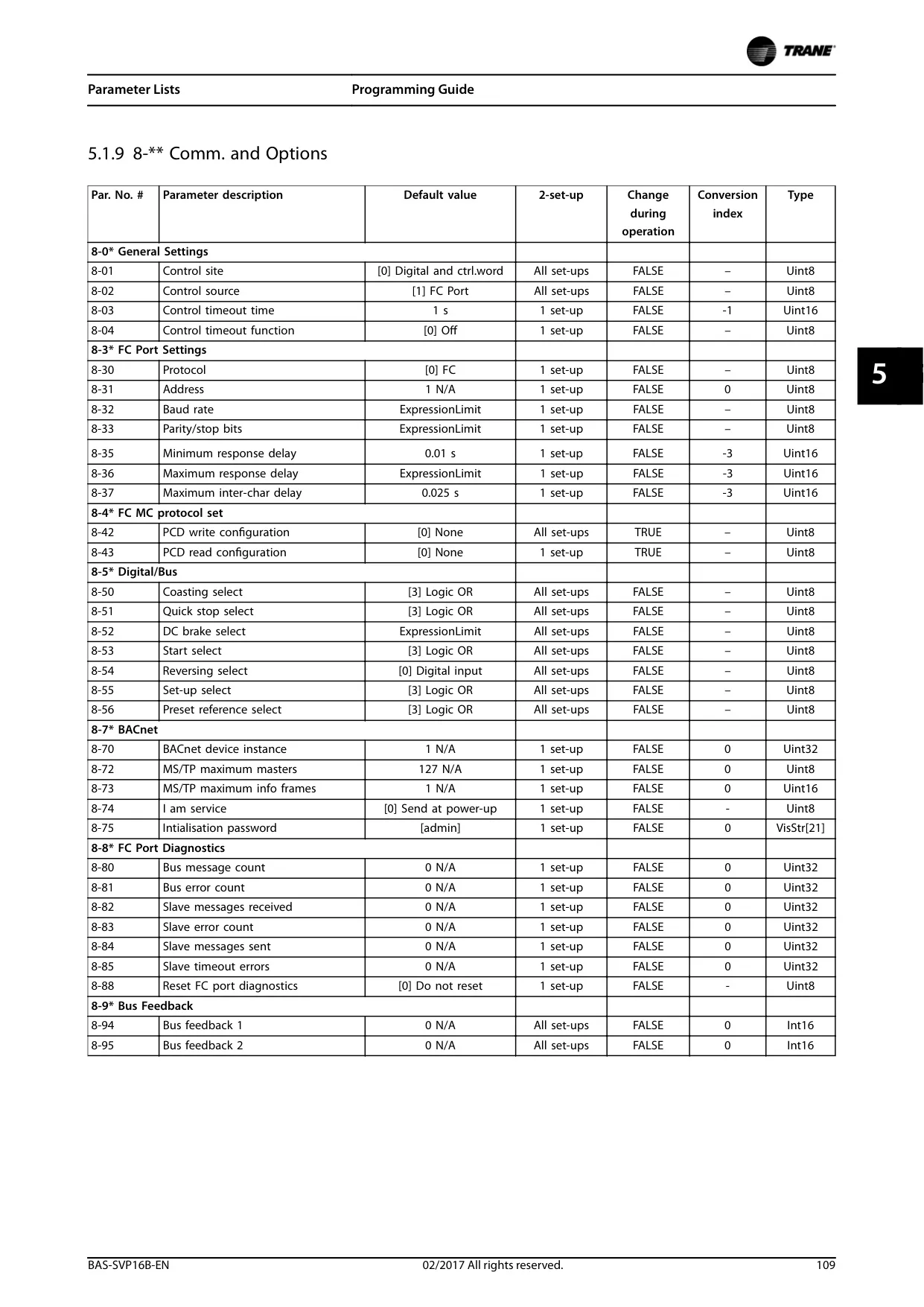
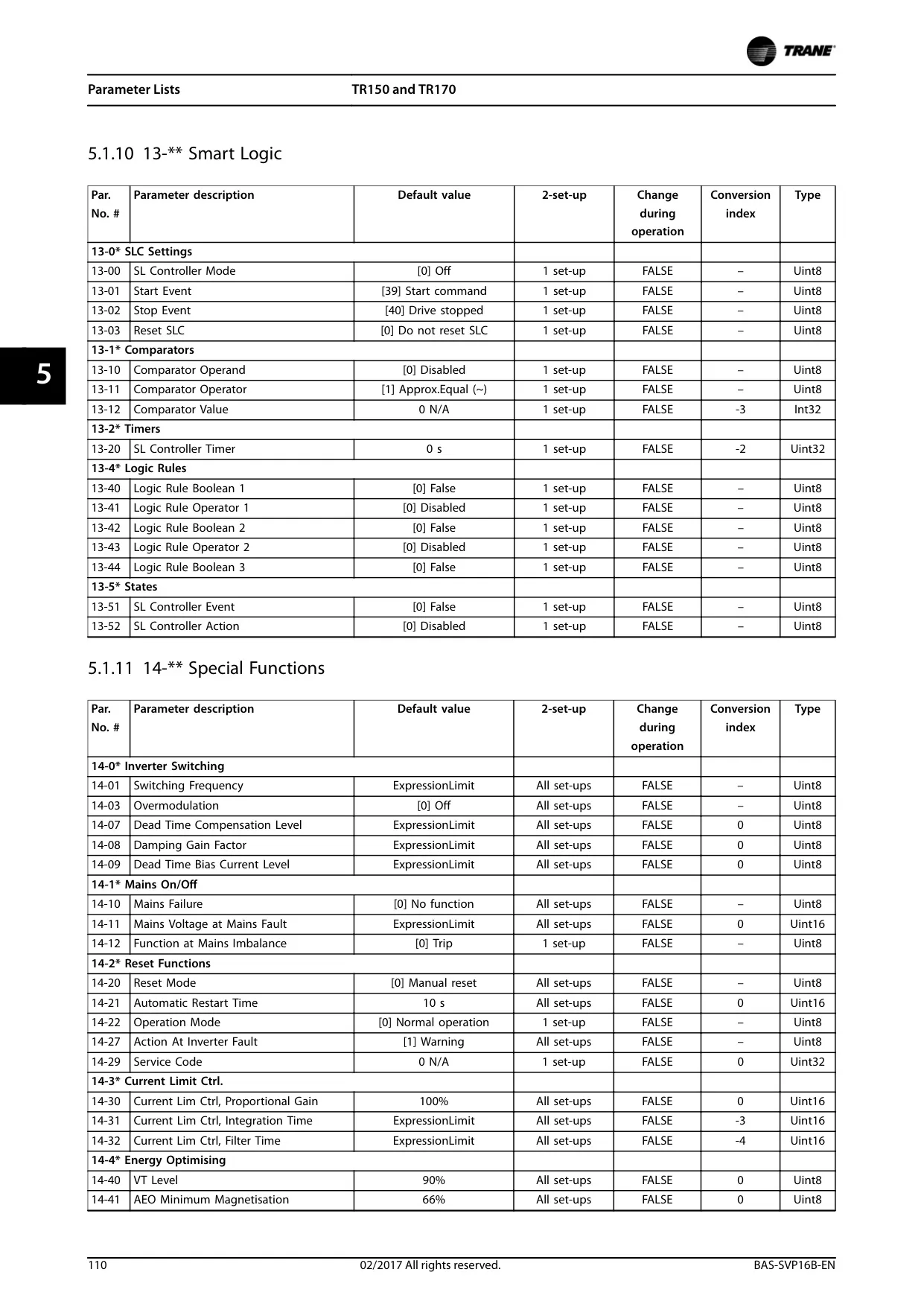
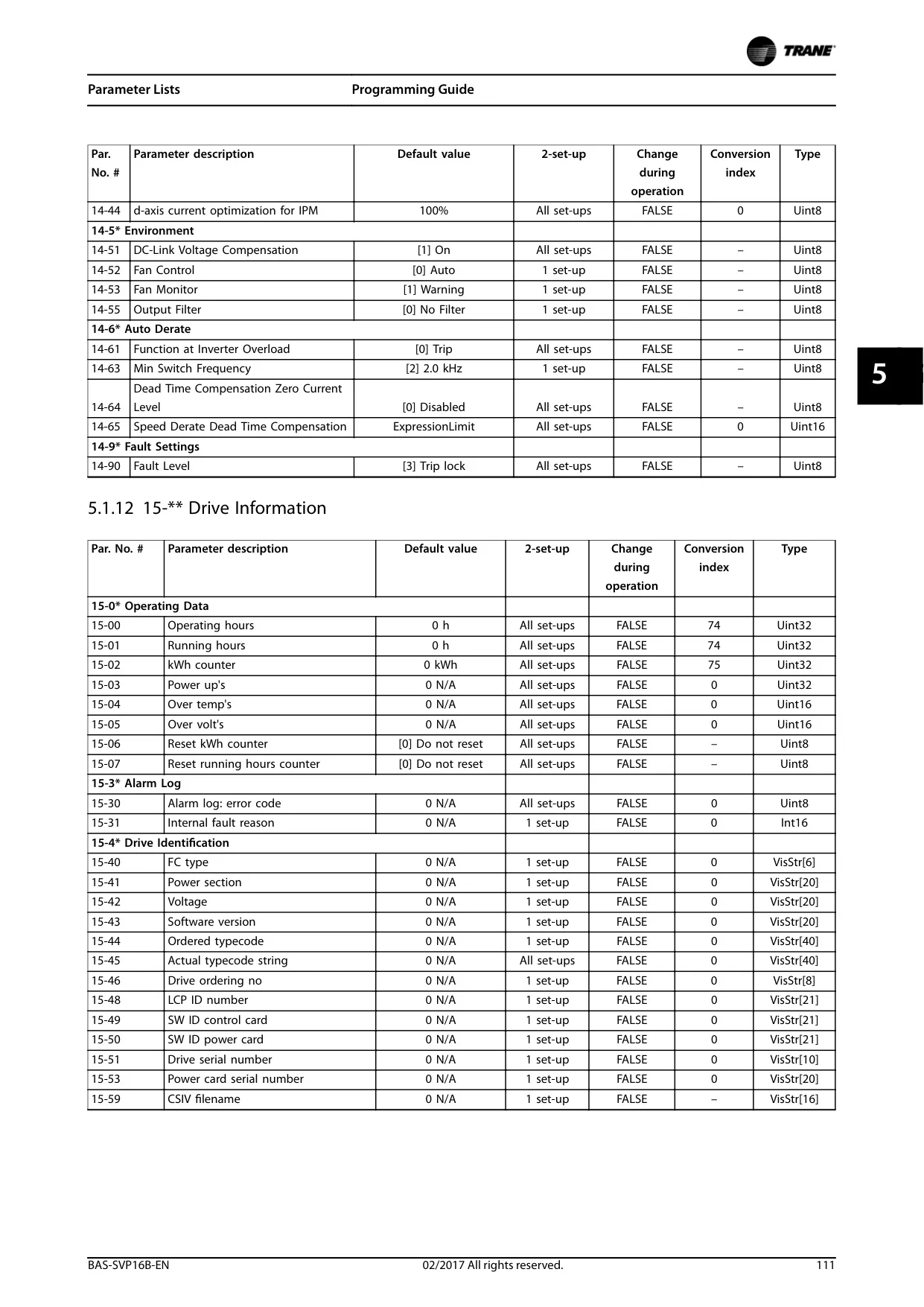
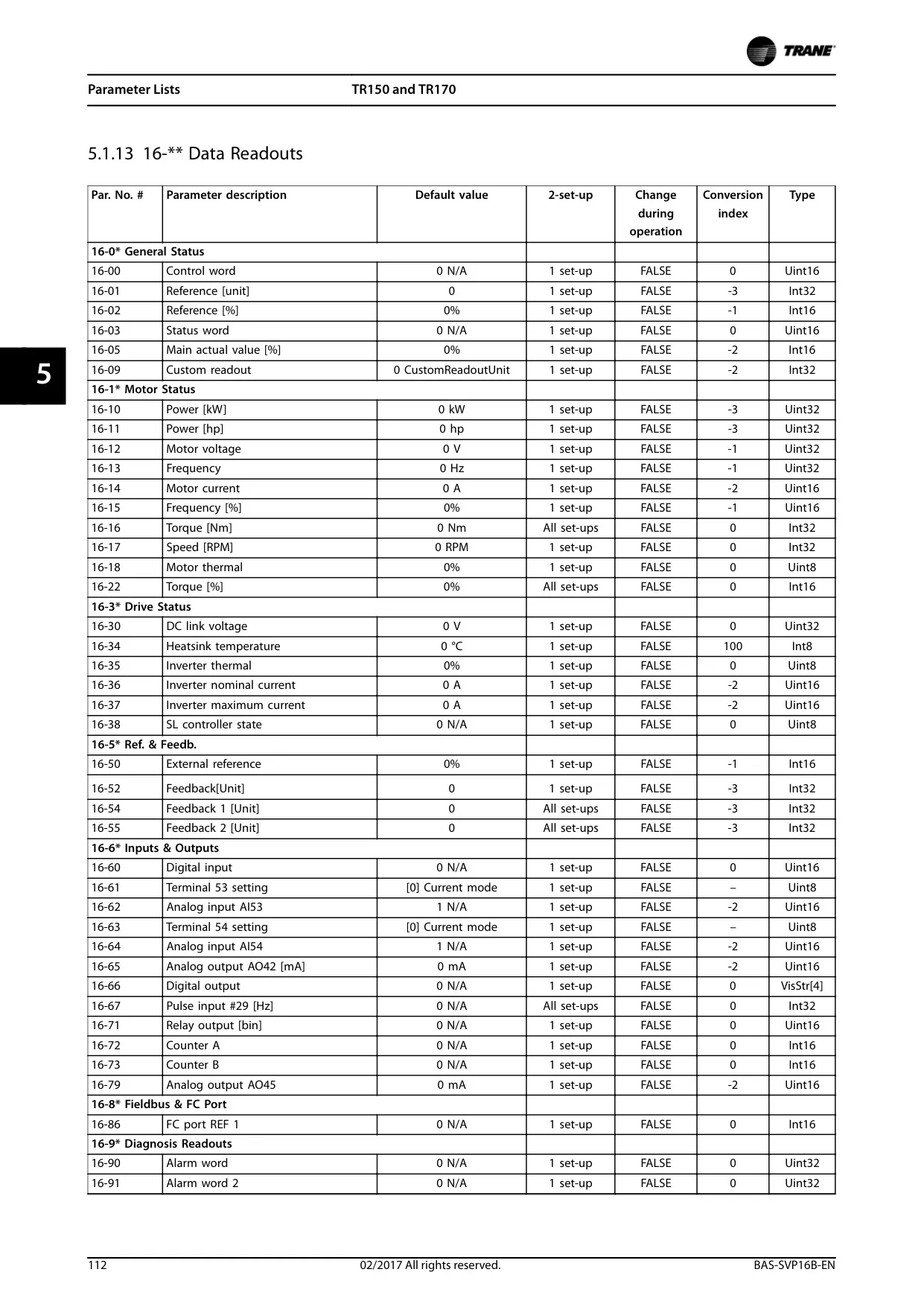


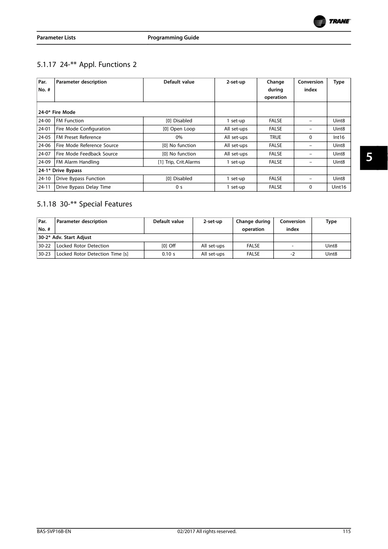



Trane TR150 Variable Frequency Drive
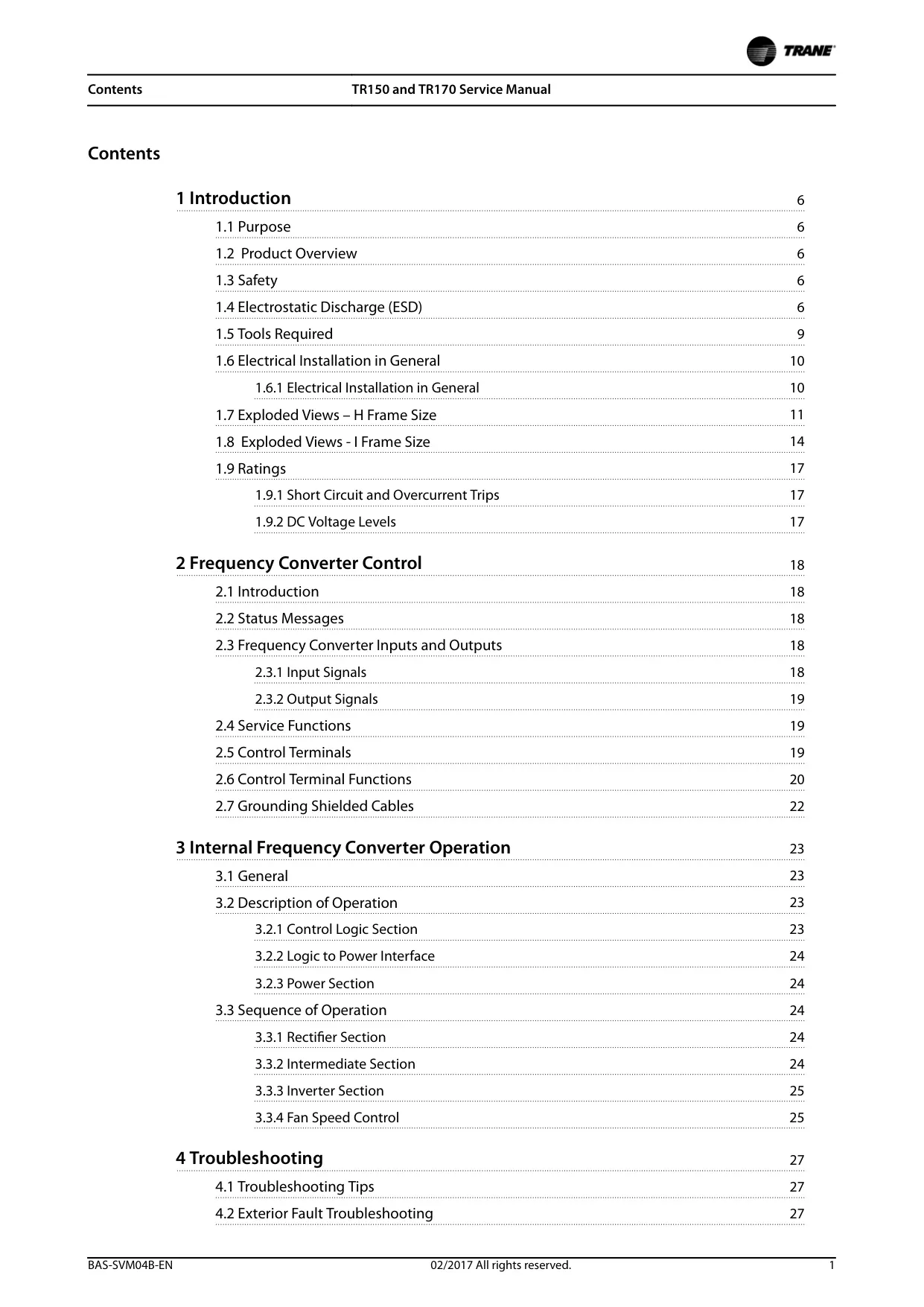
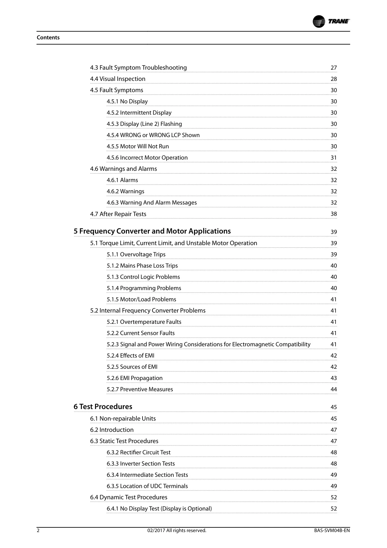
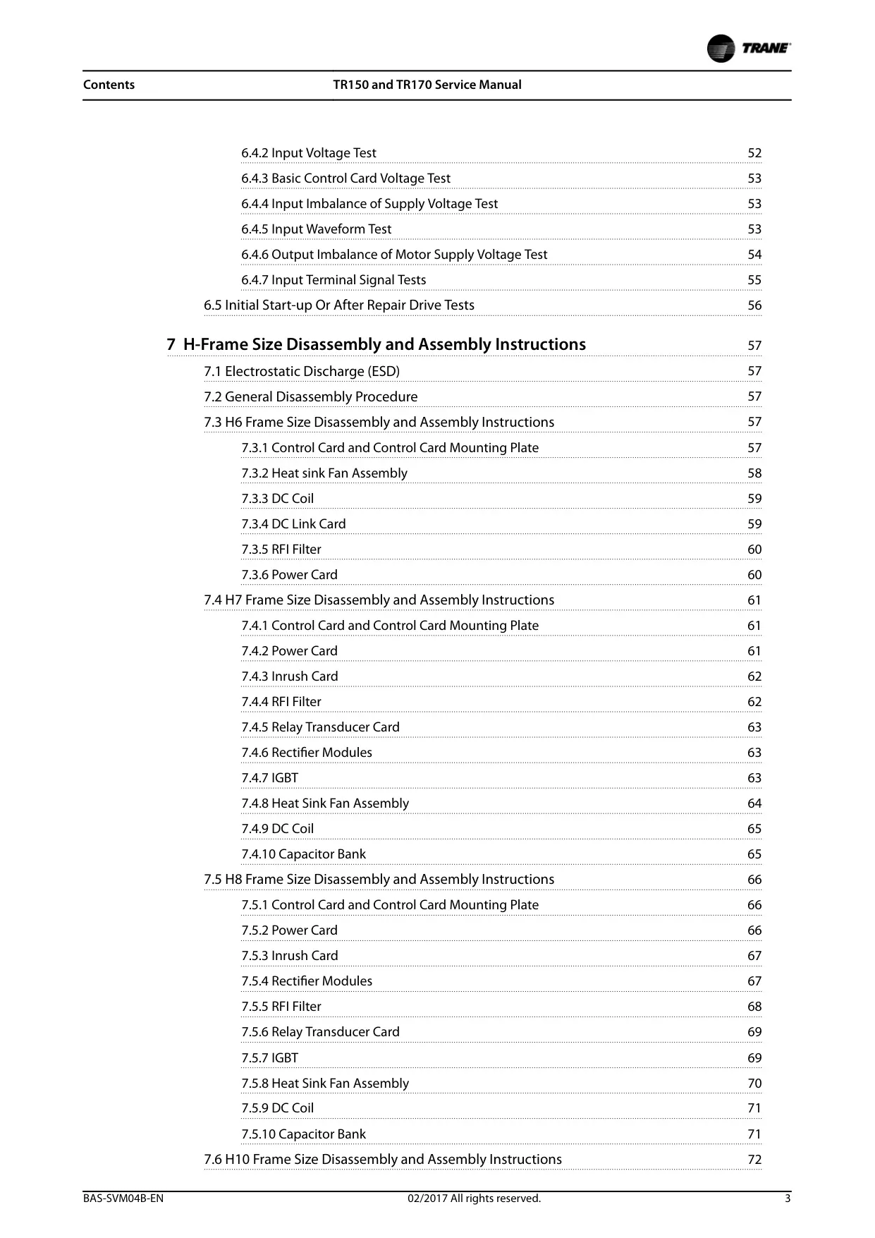
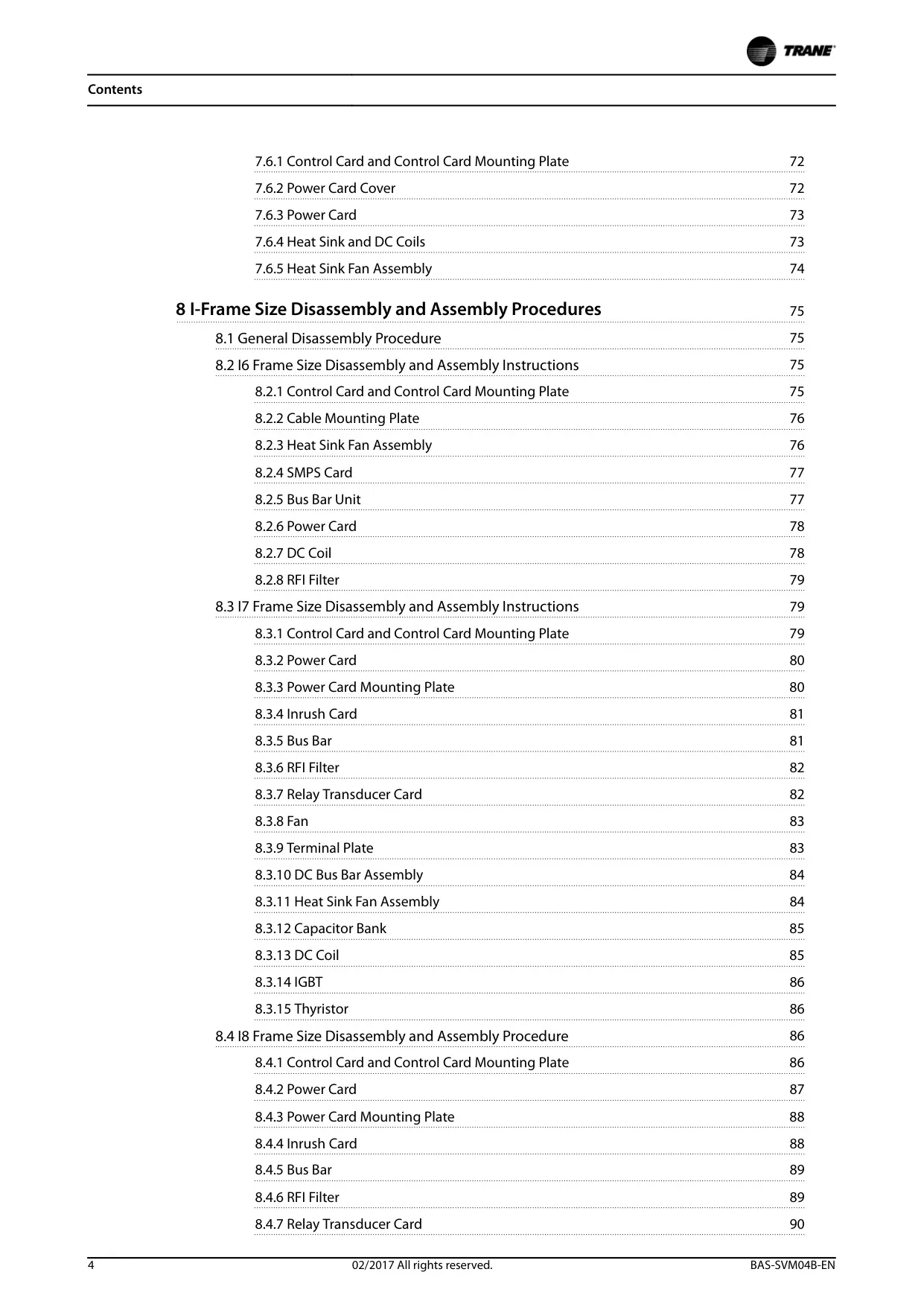

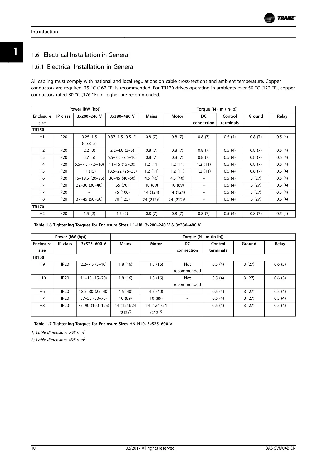
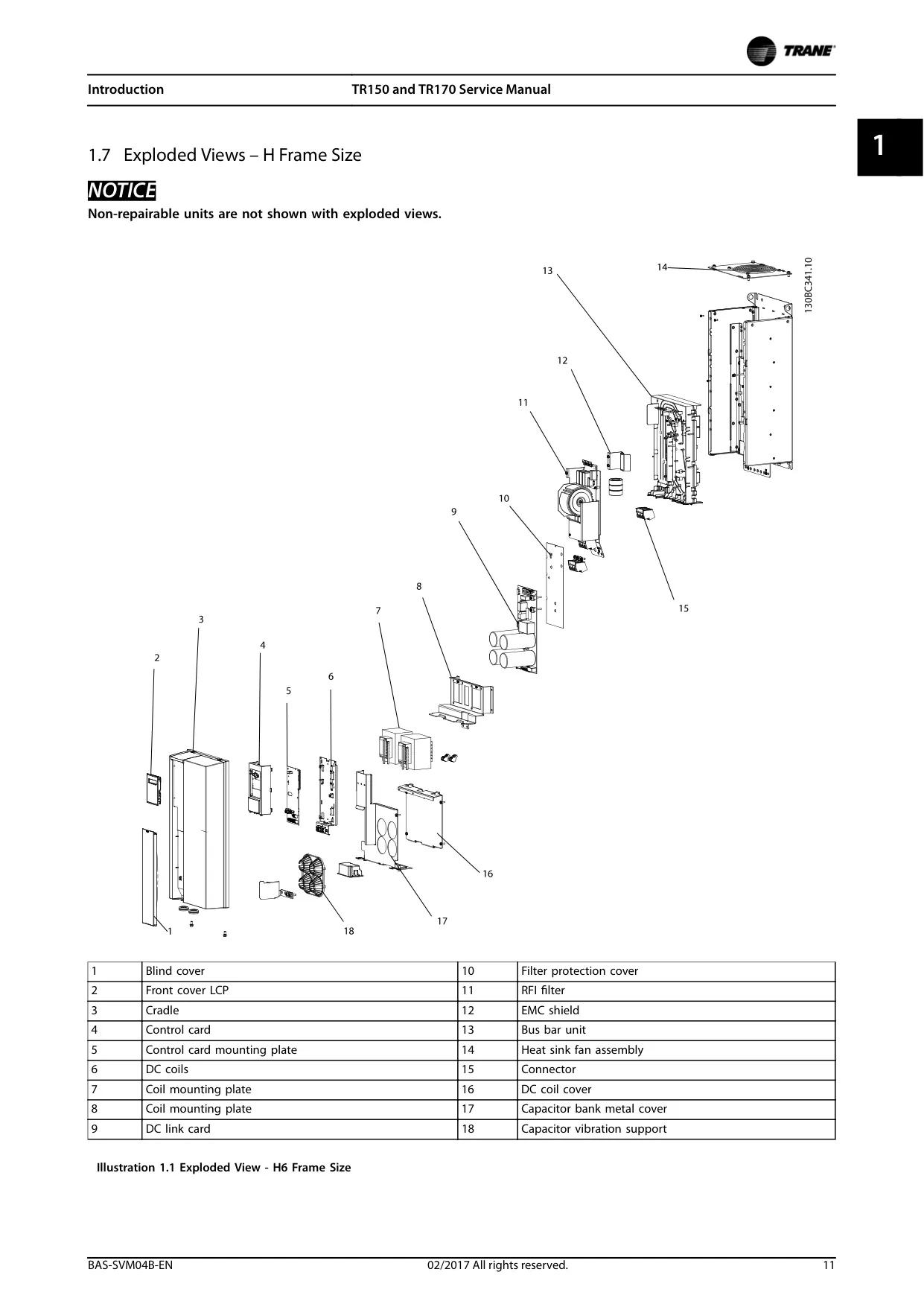
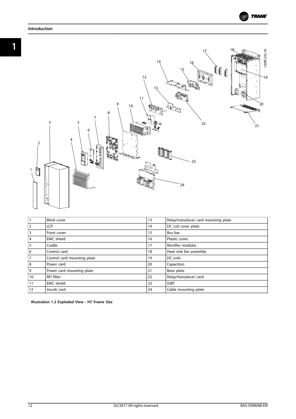
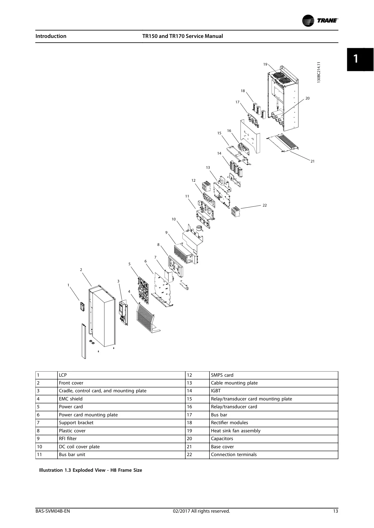

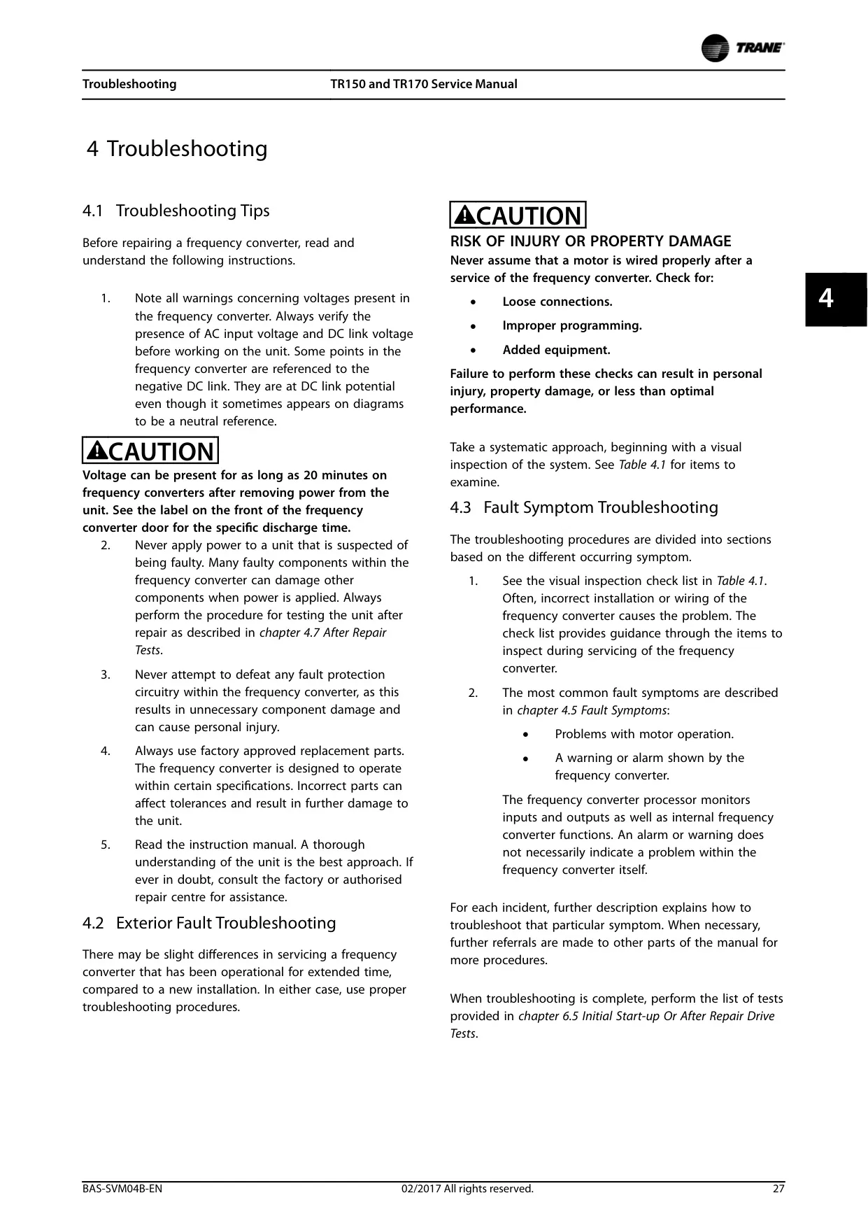
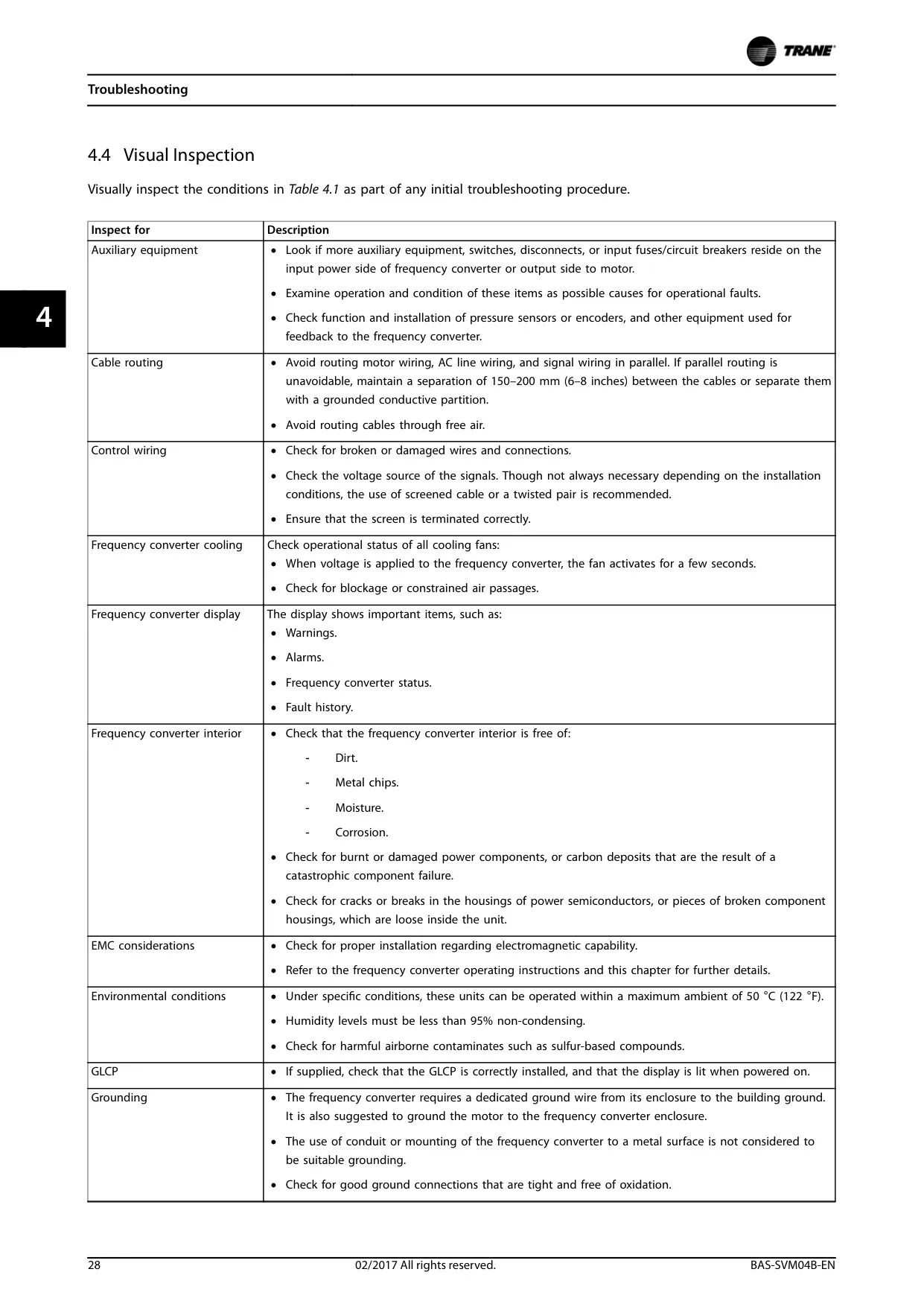

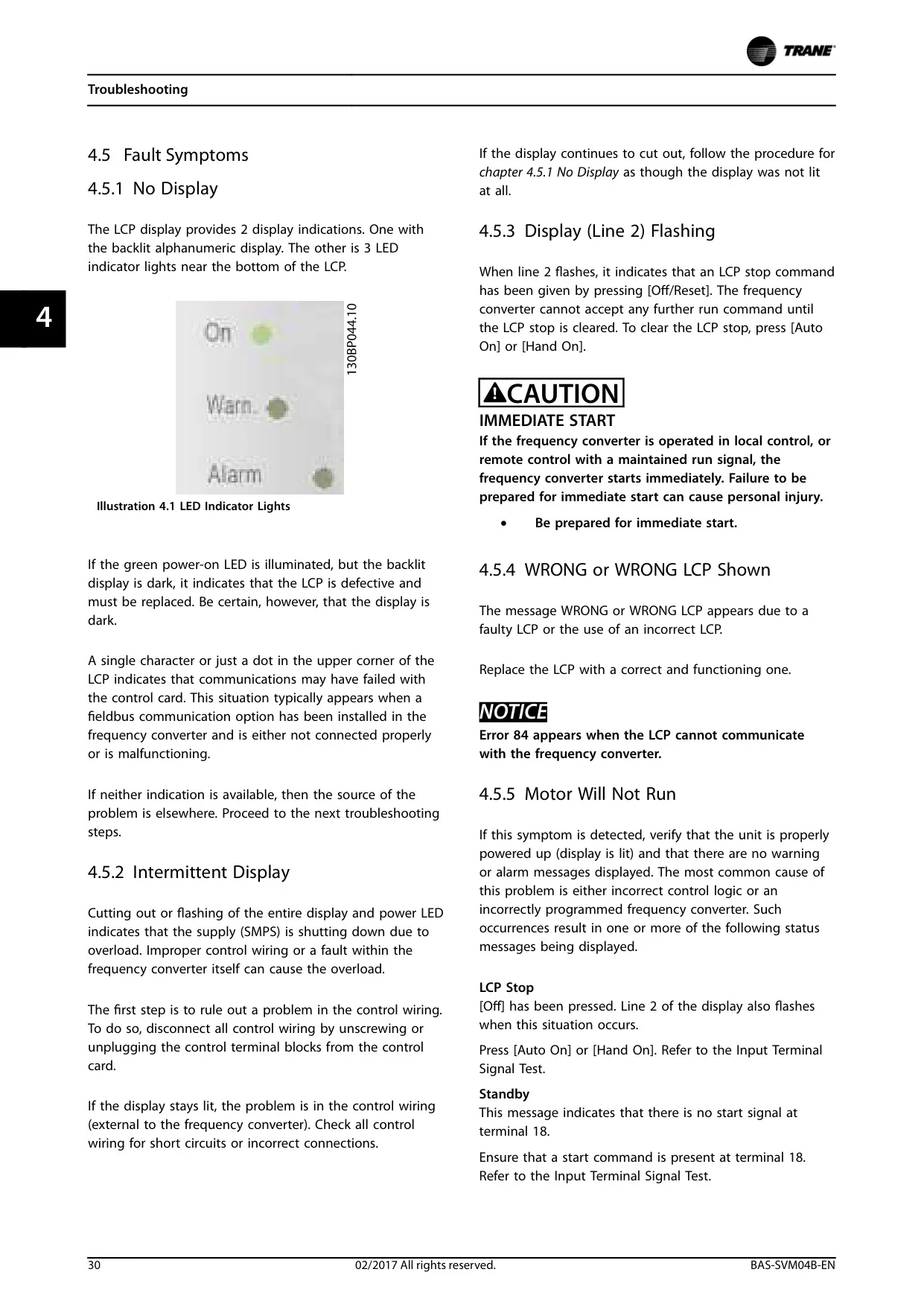
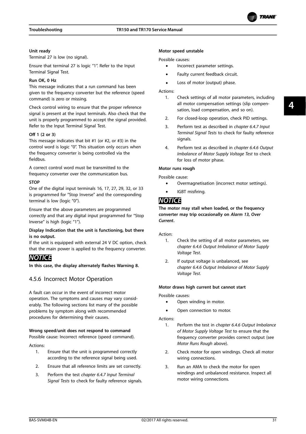
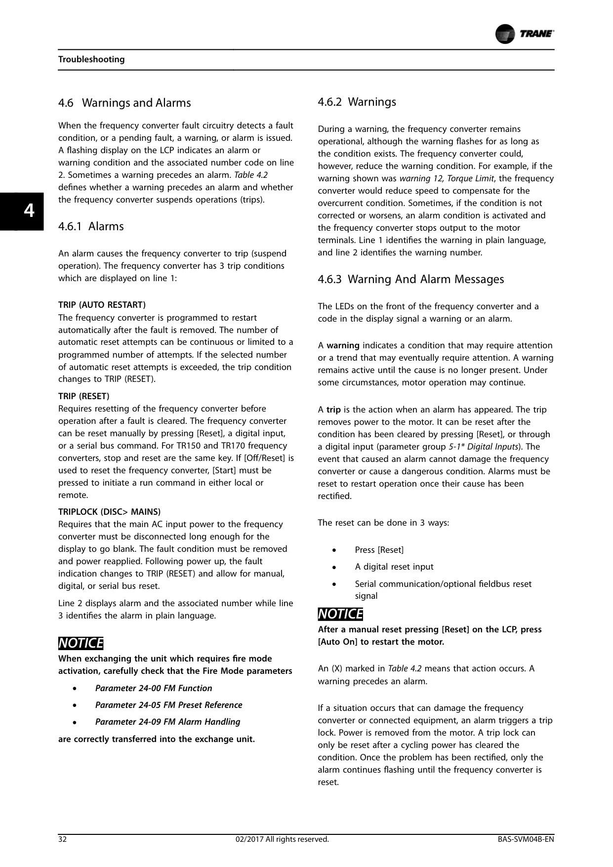
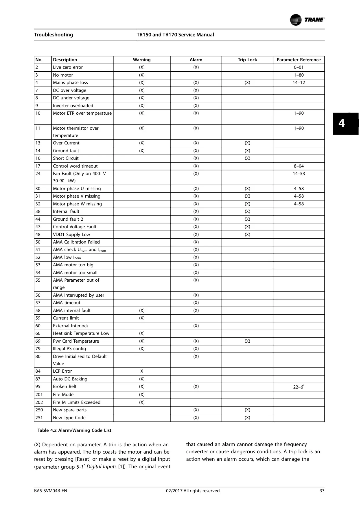
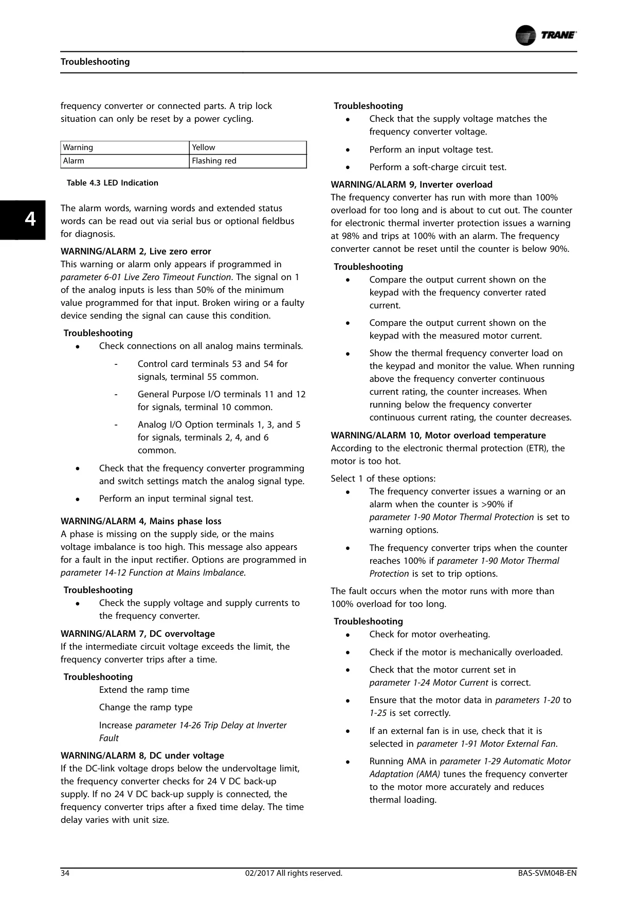
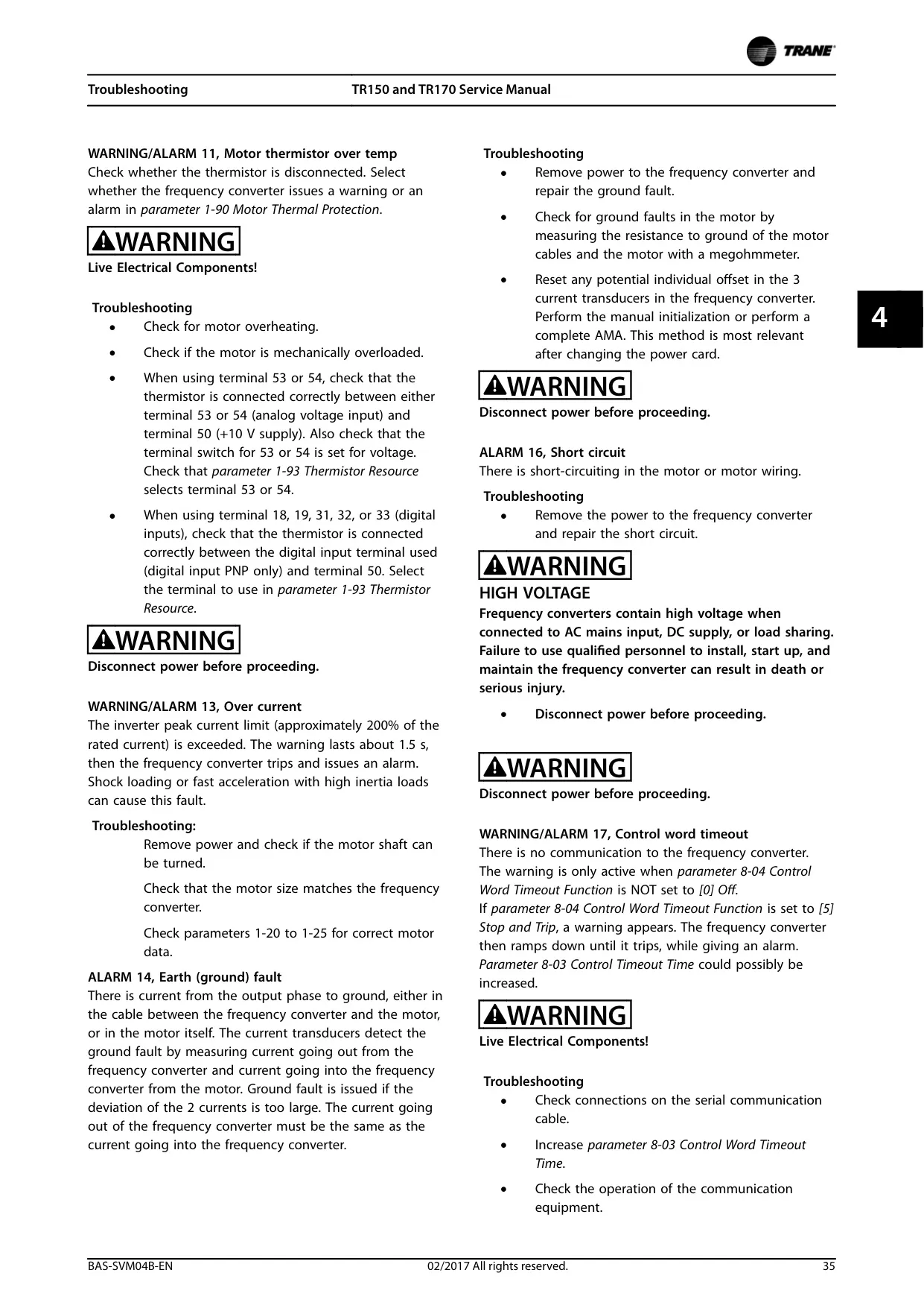
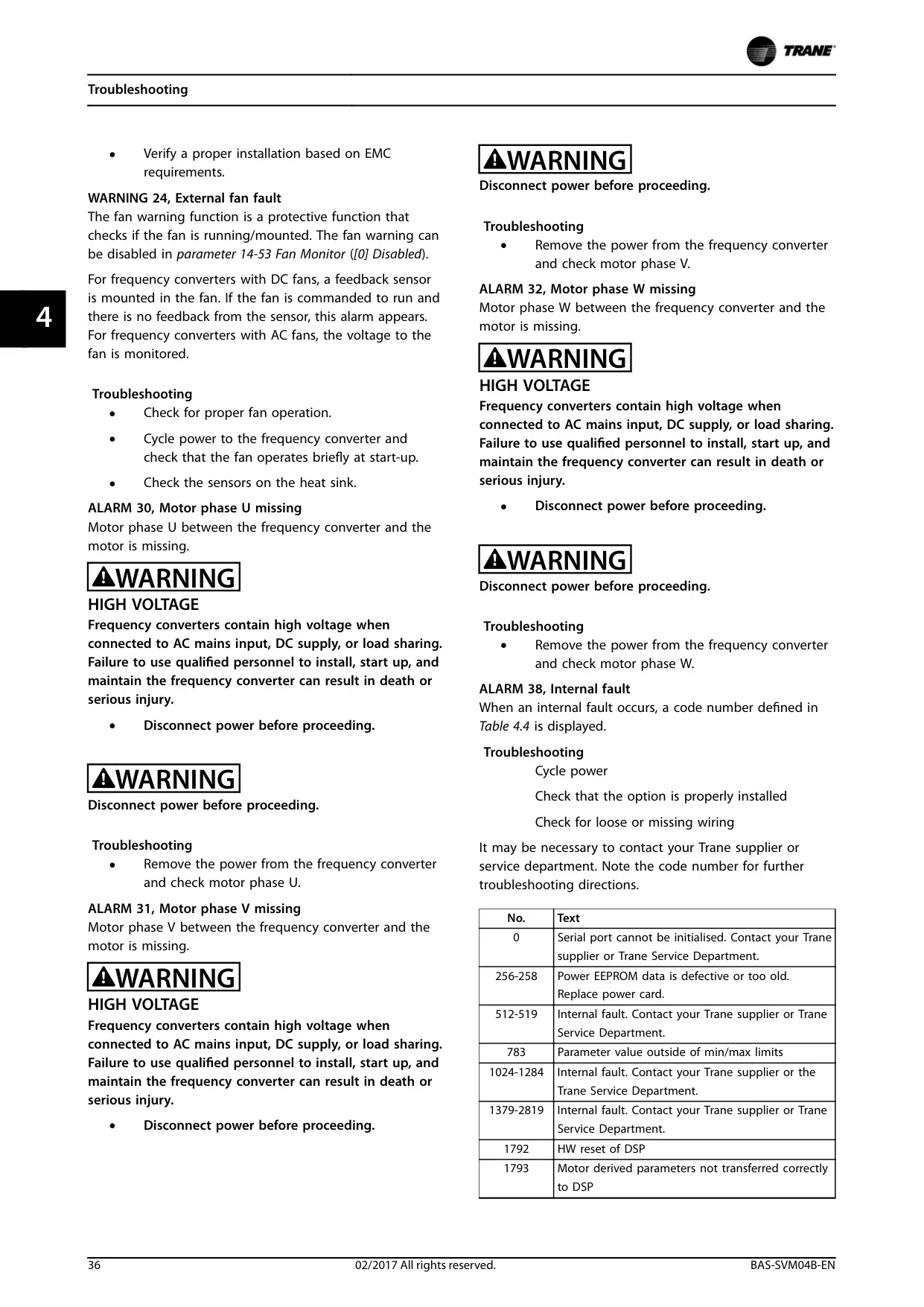
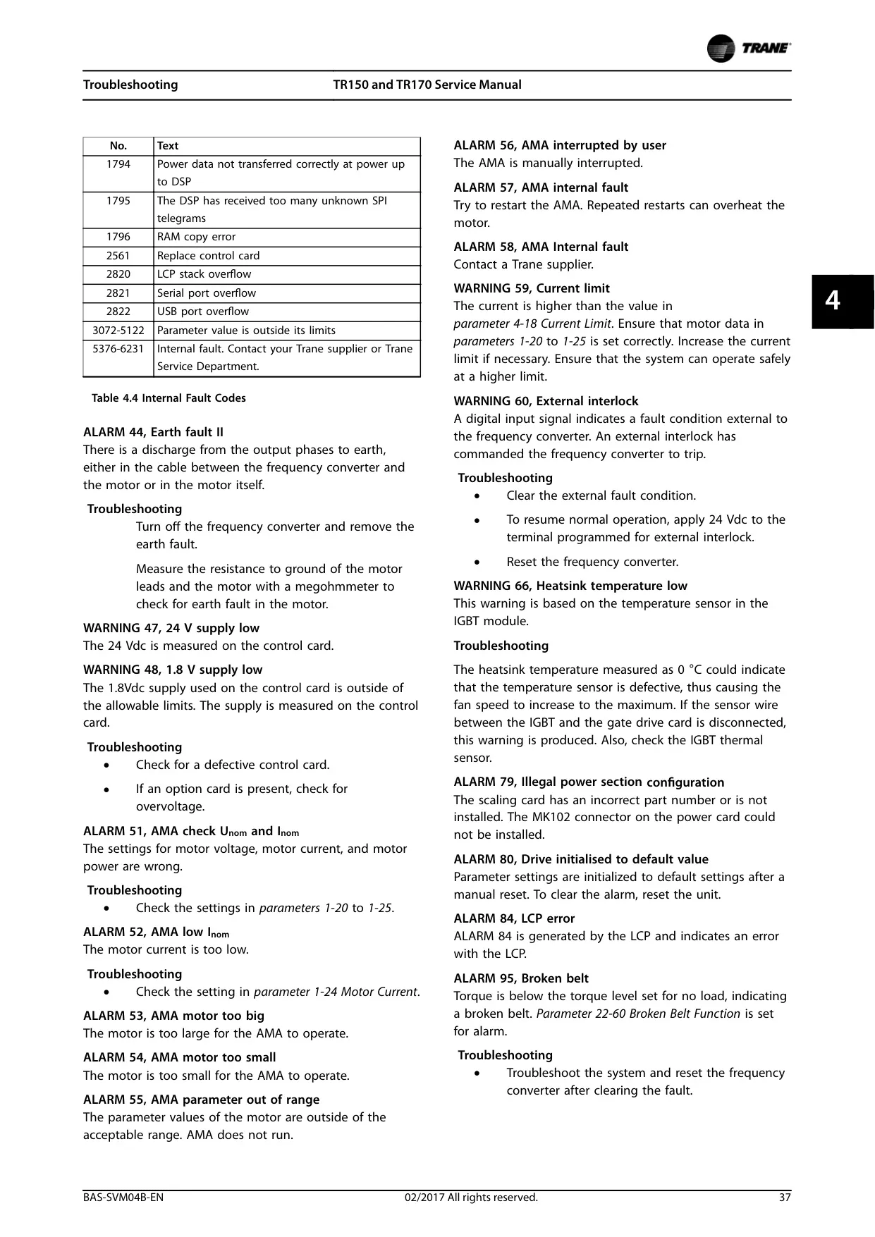
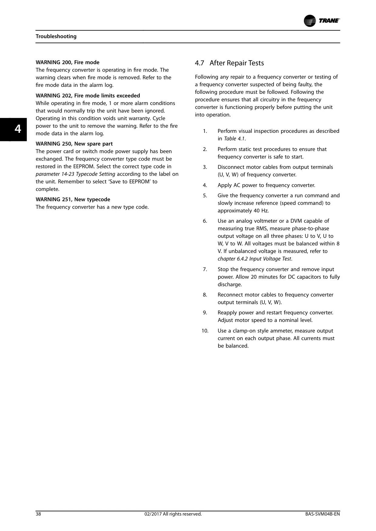
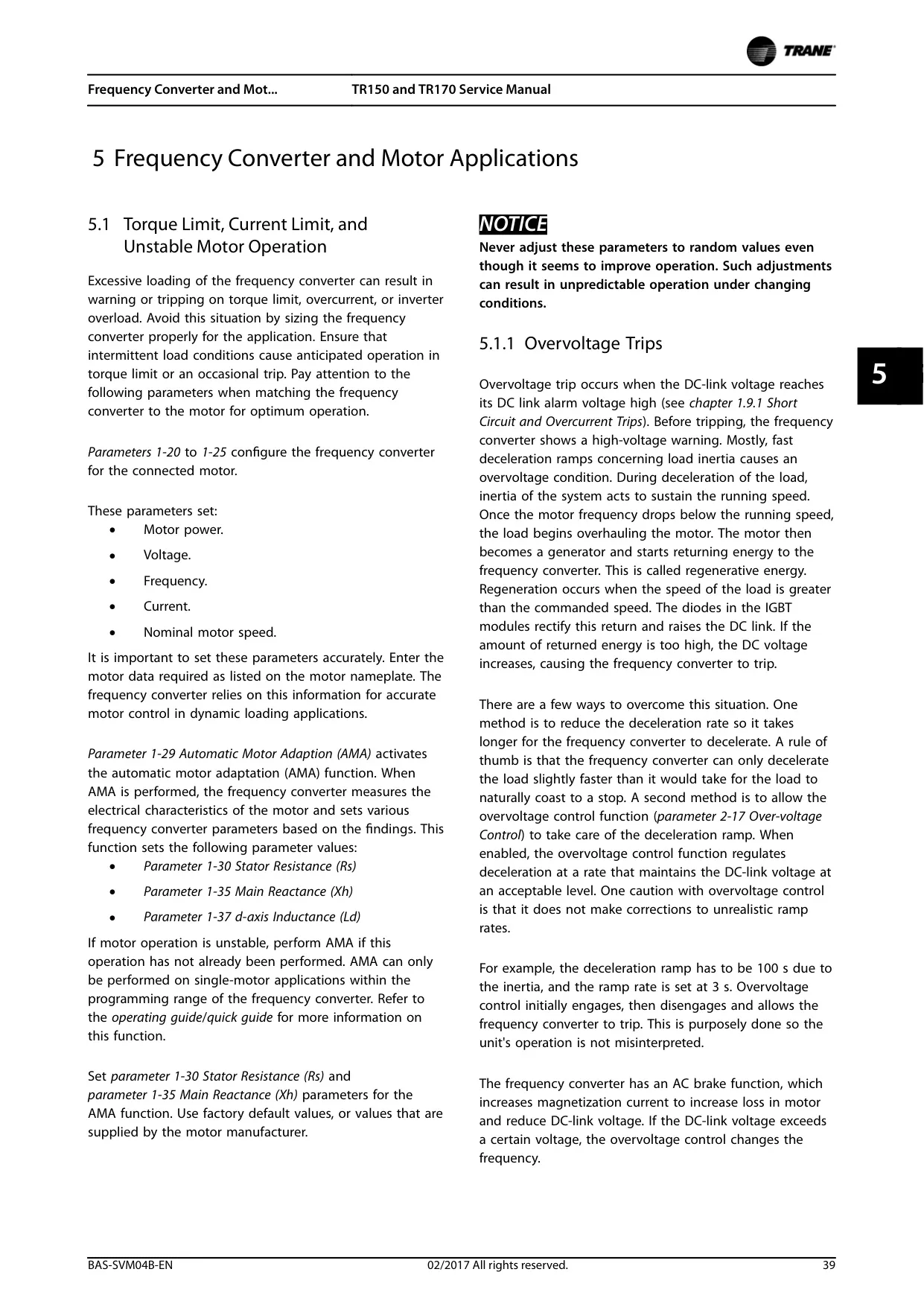
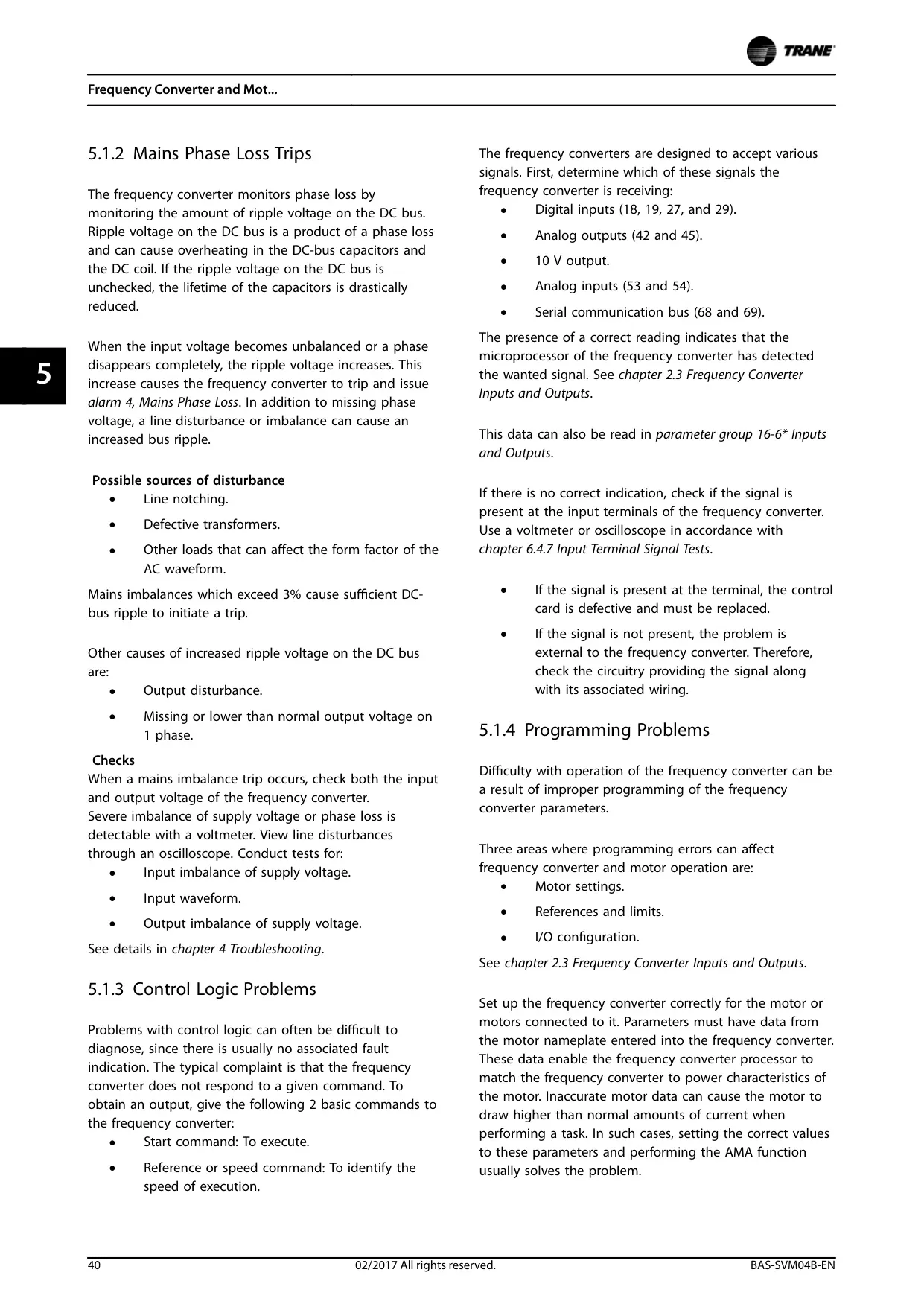
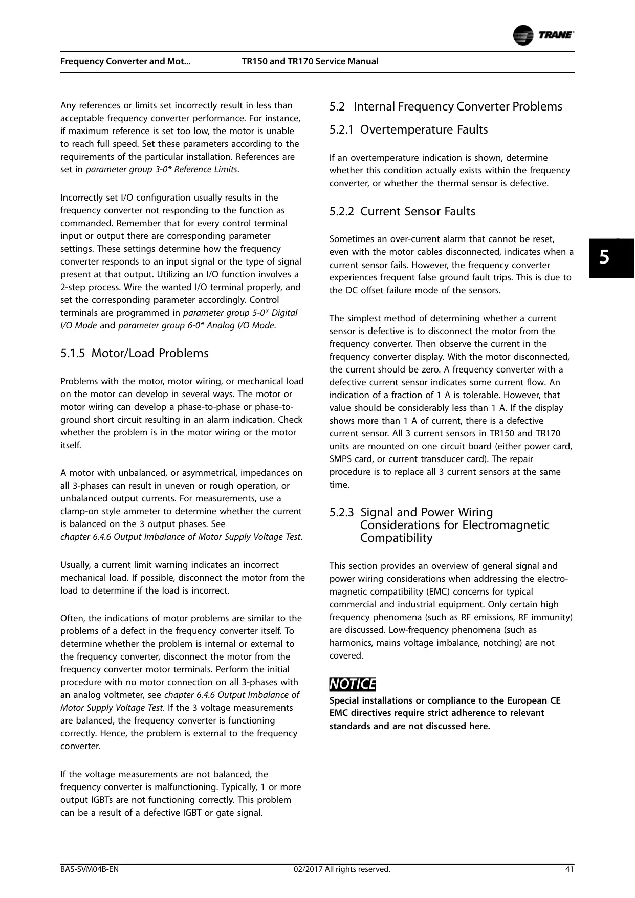
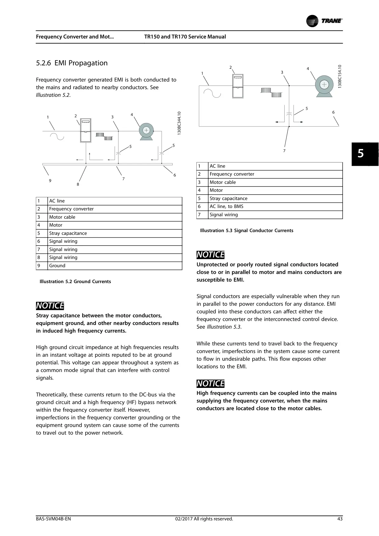
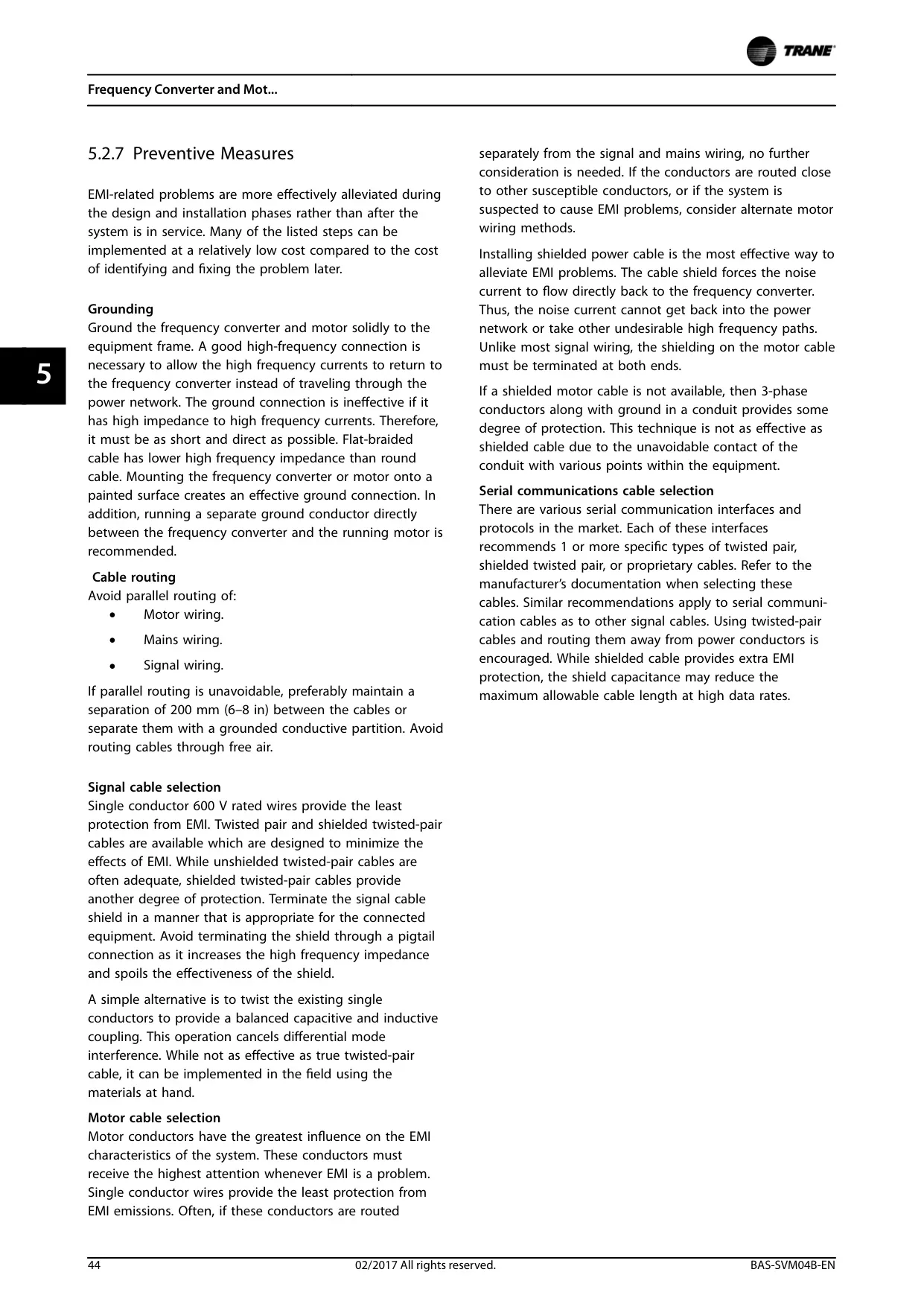
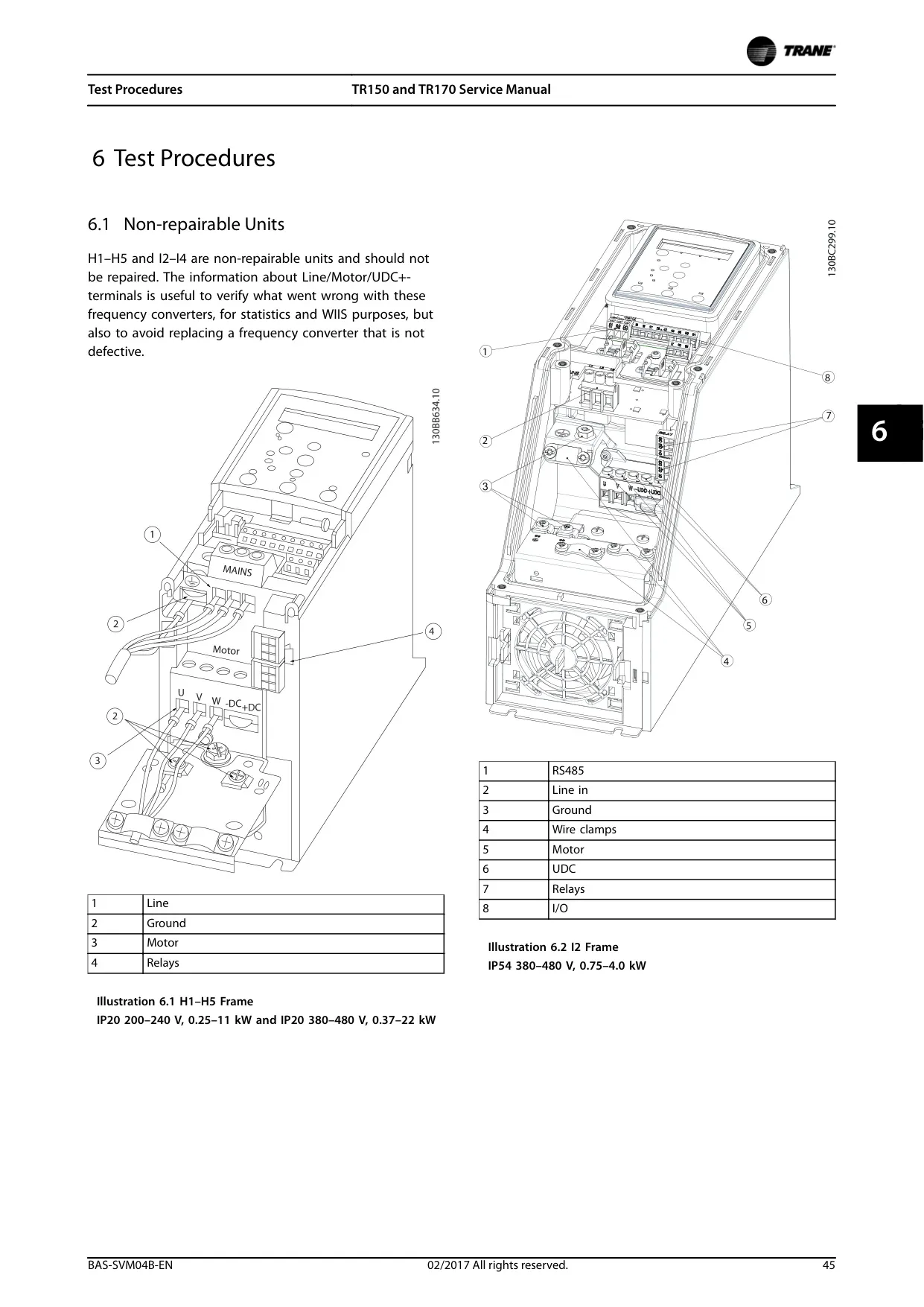
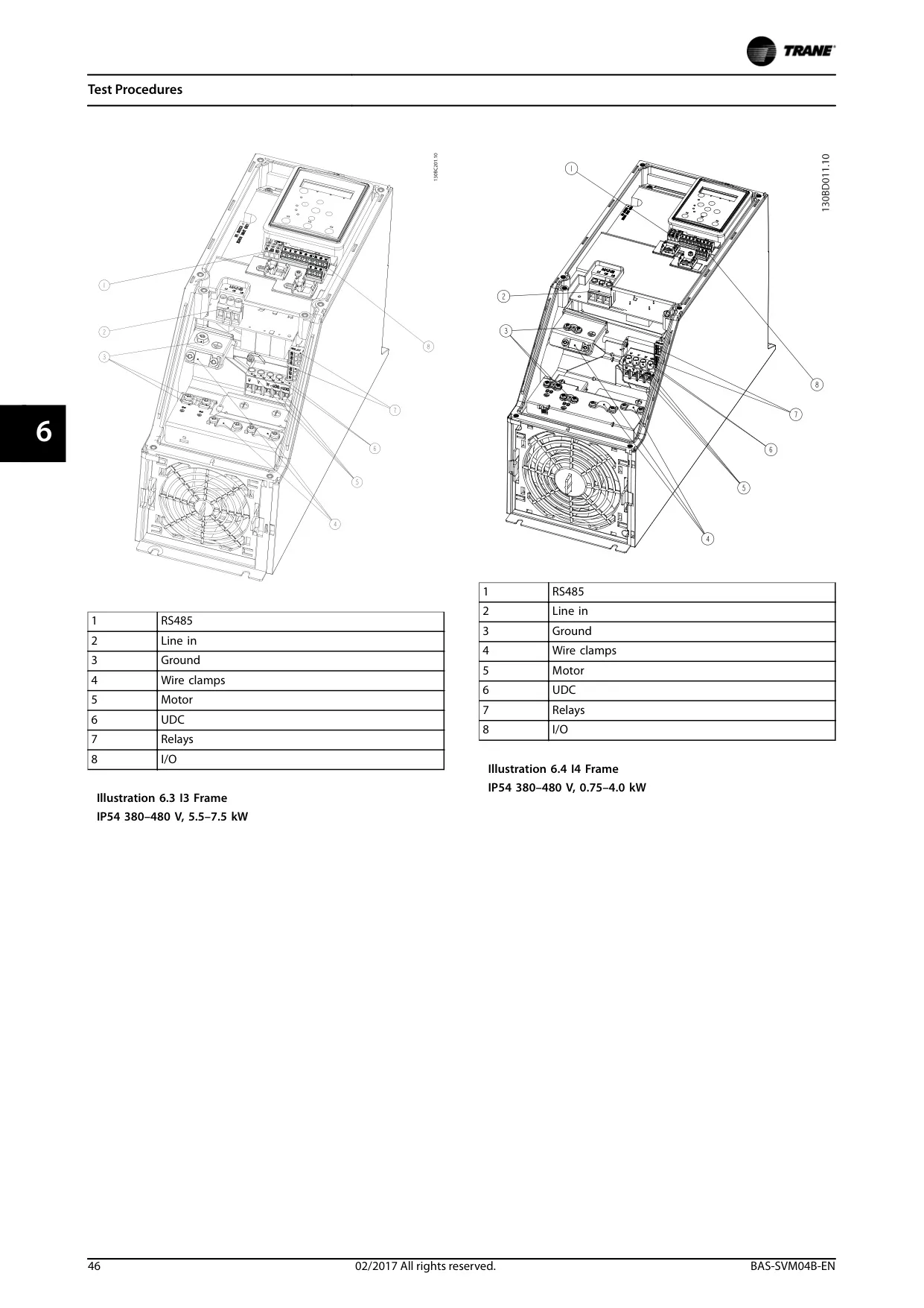
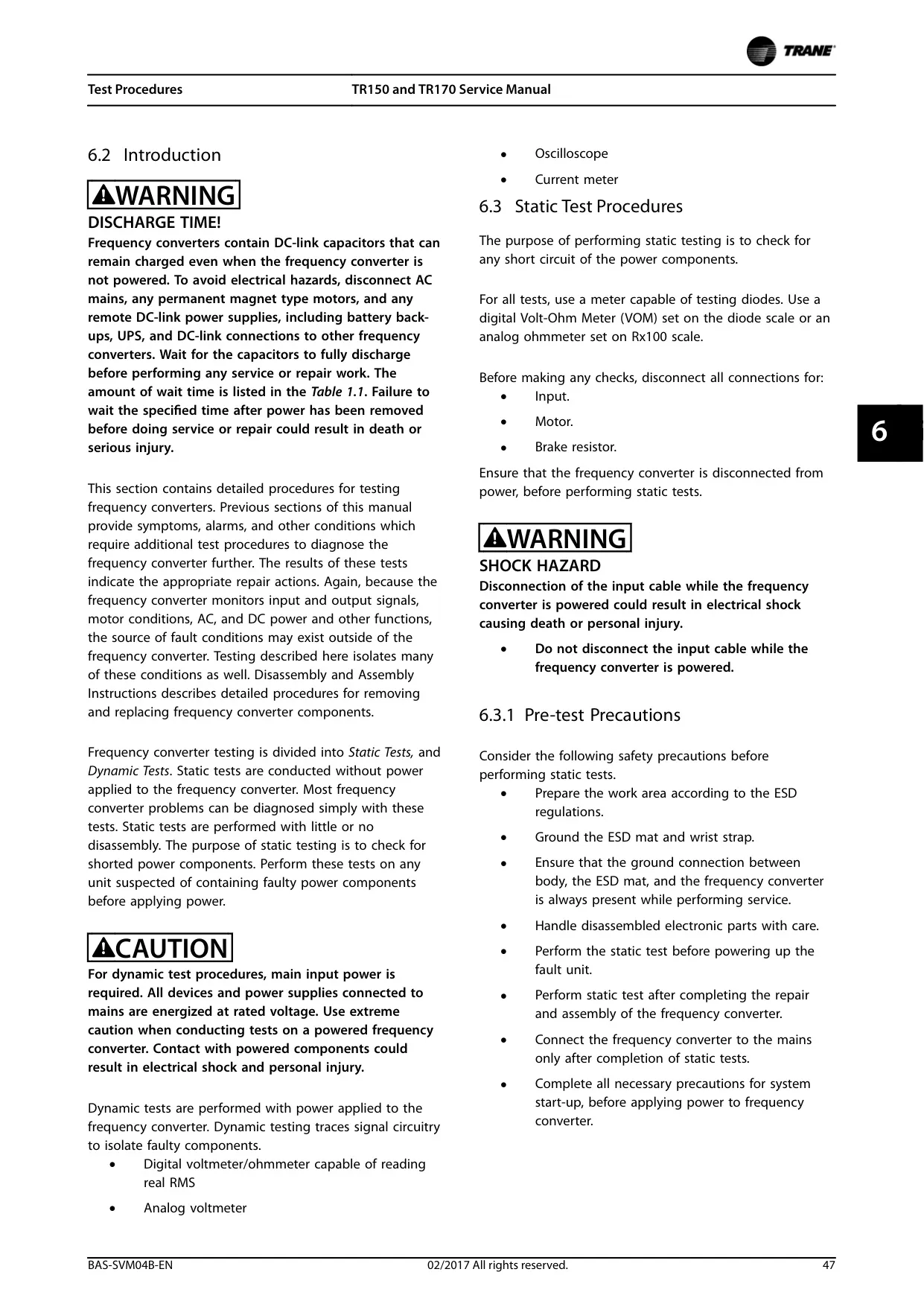
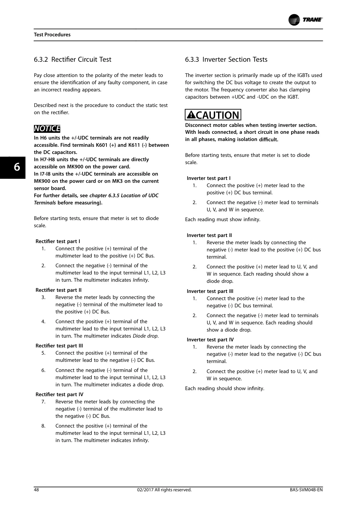
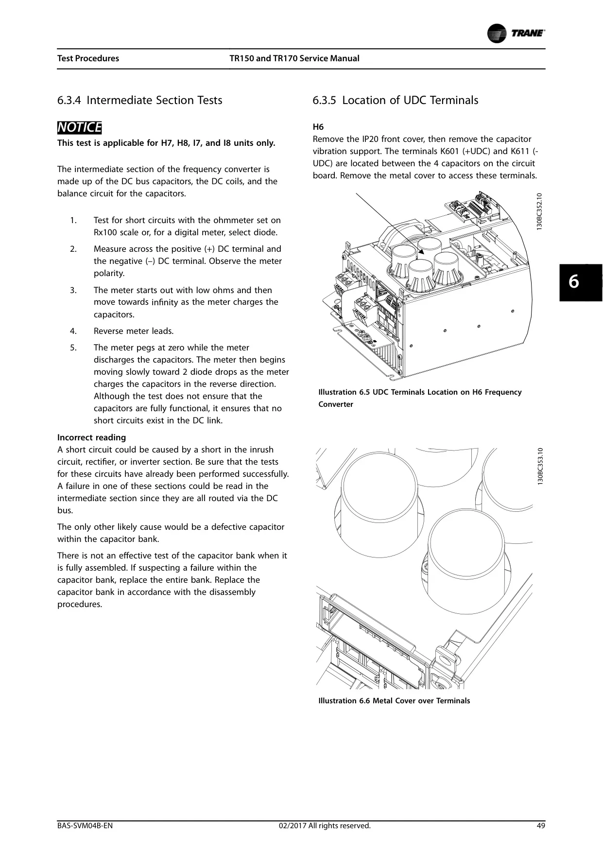
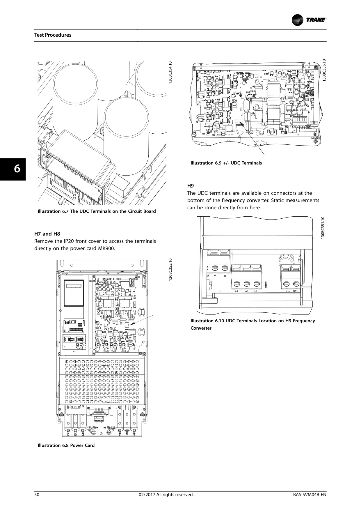
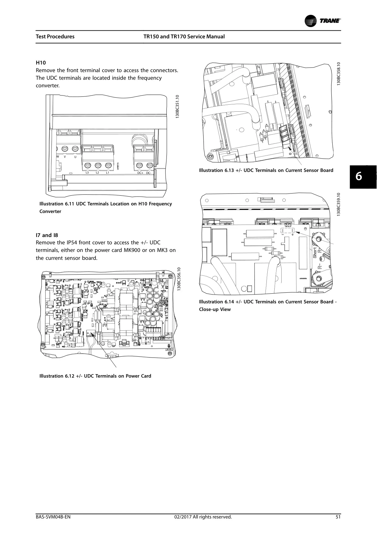
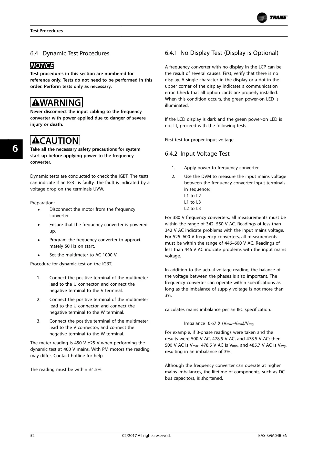
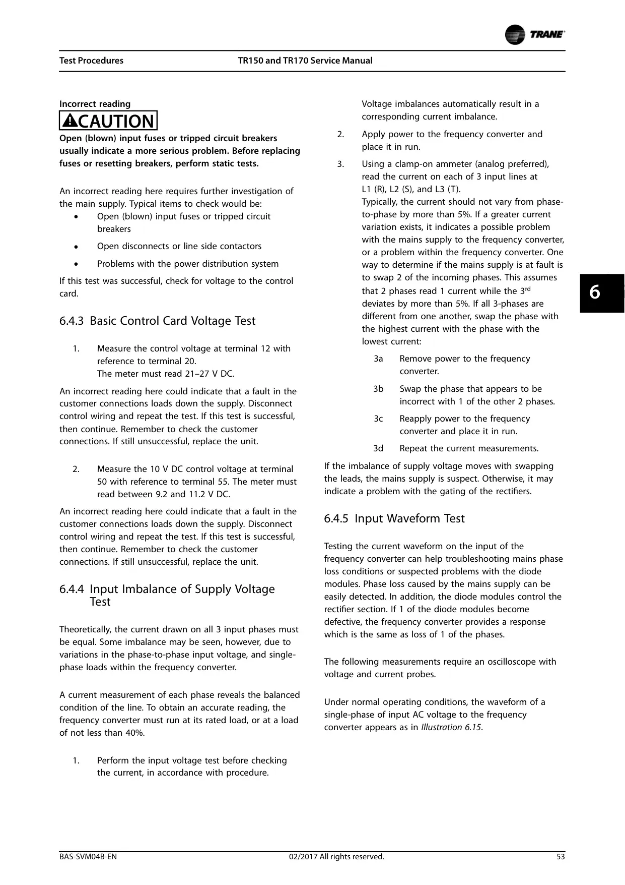
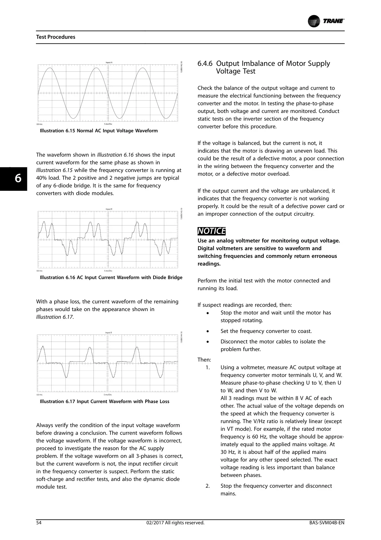
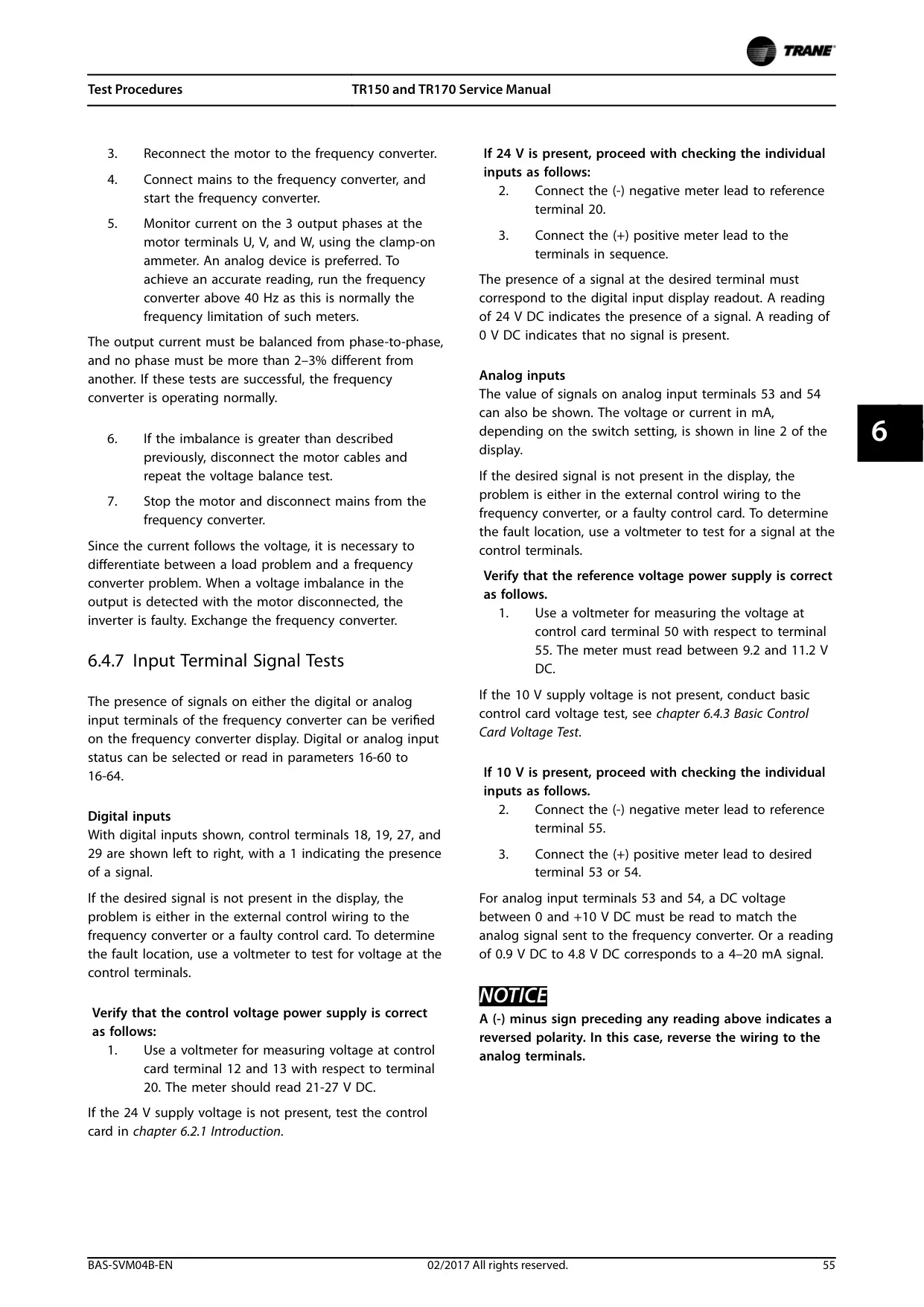
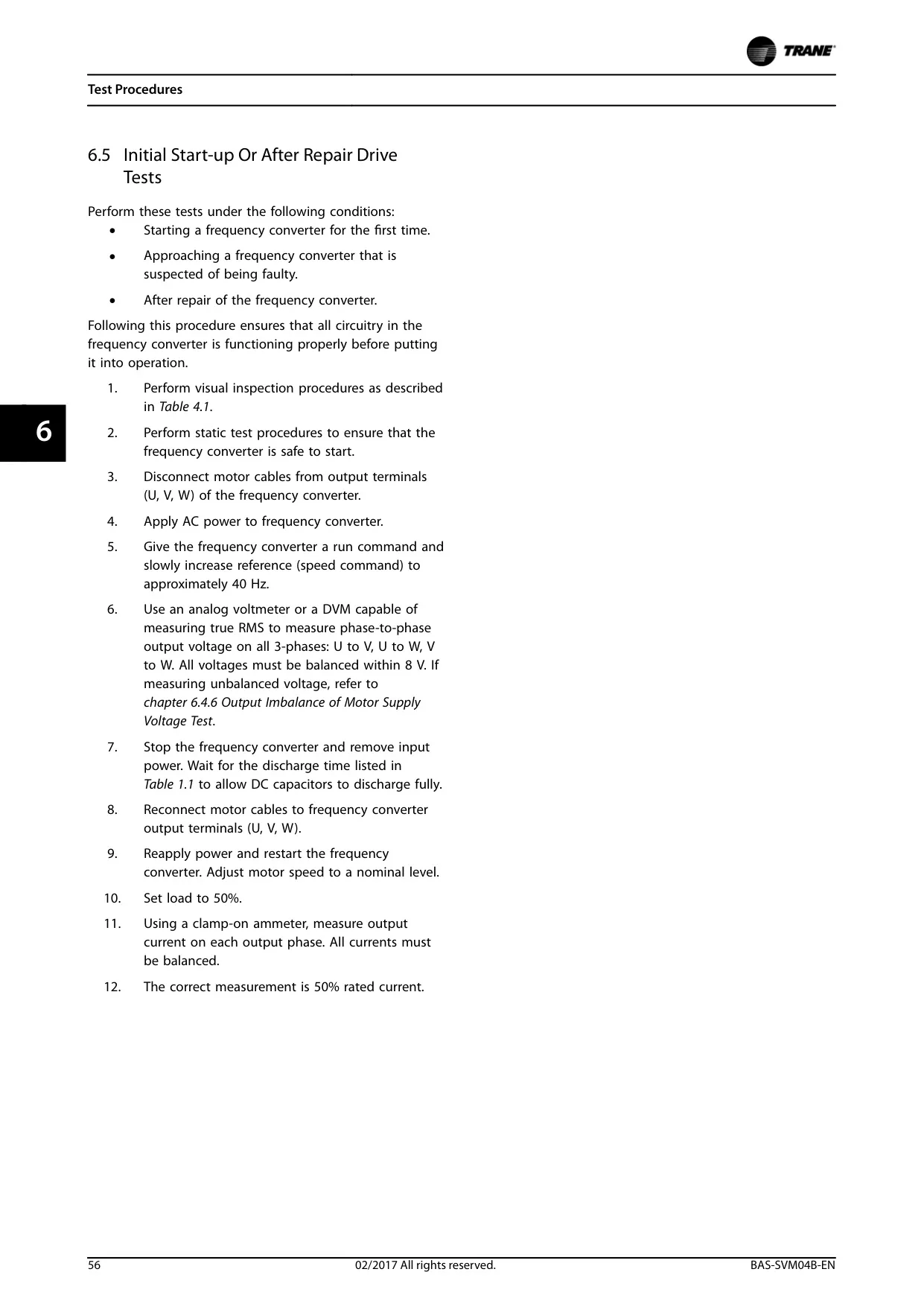
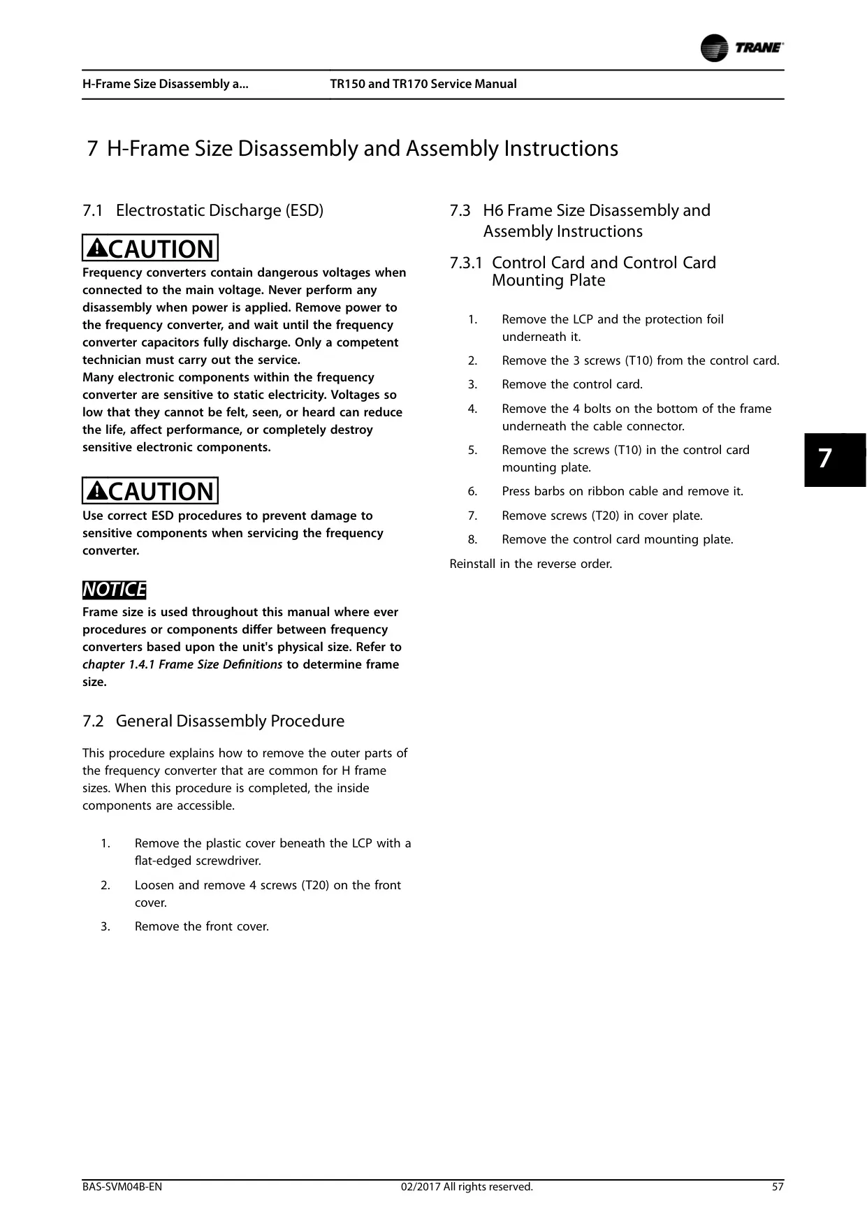
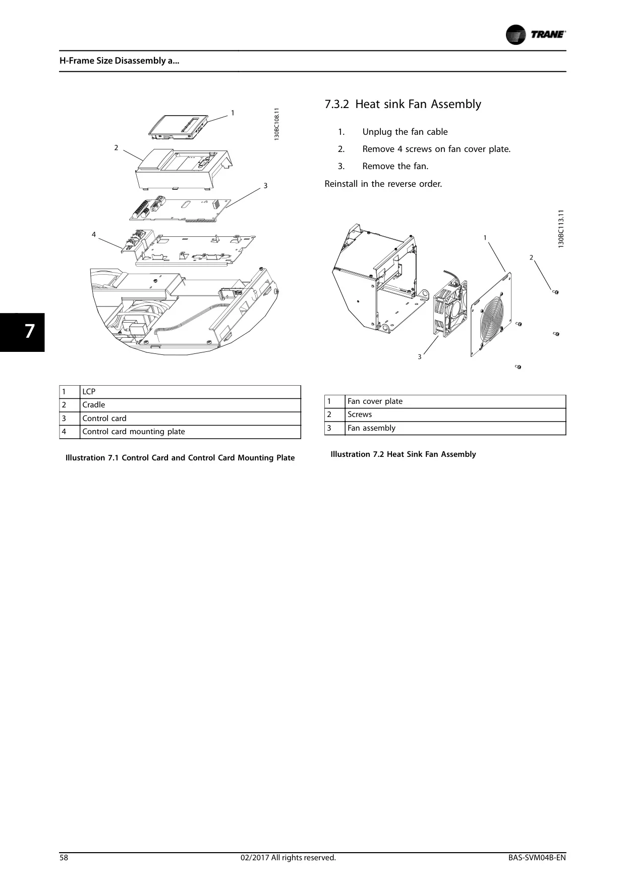
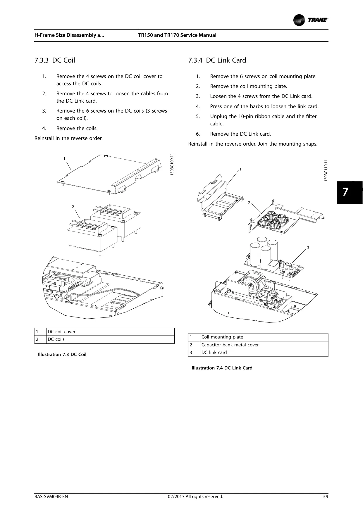
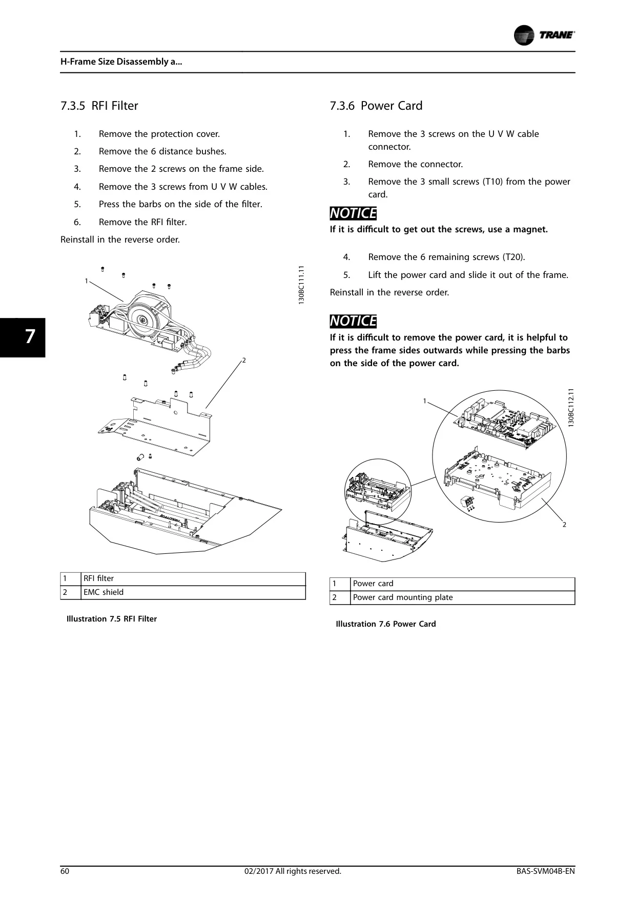
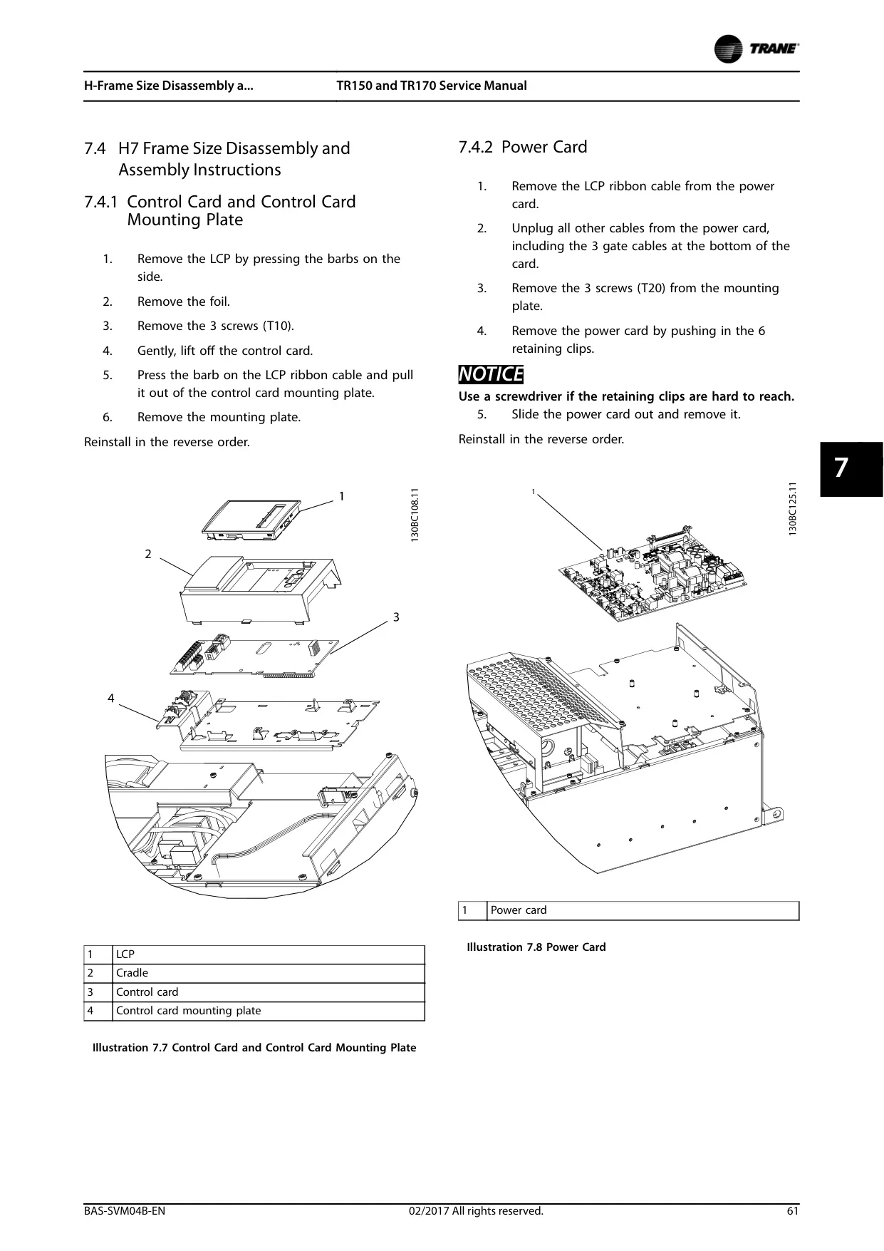
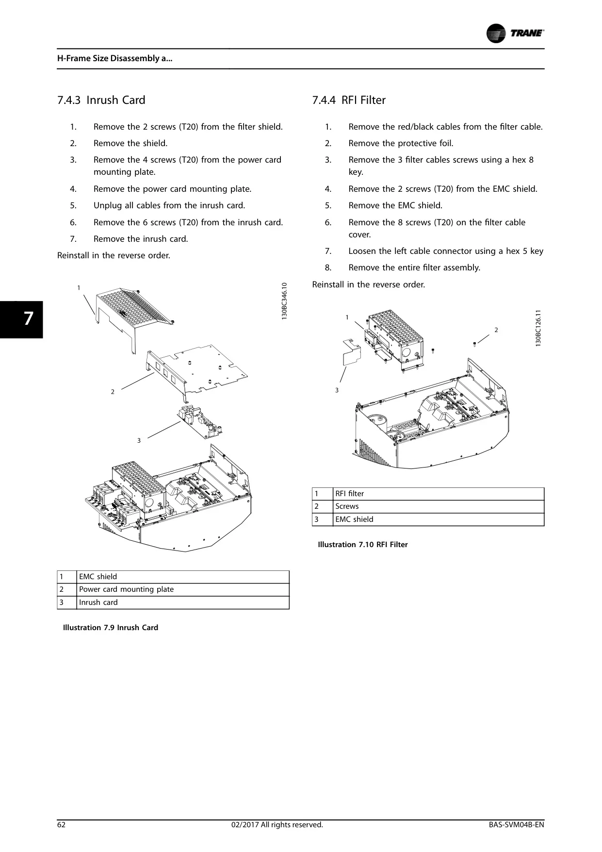
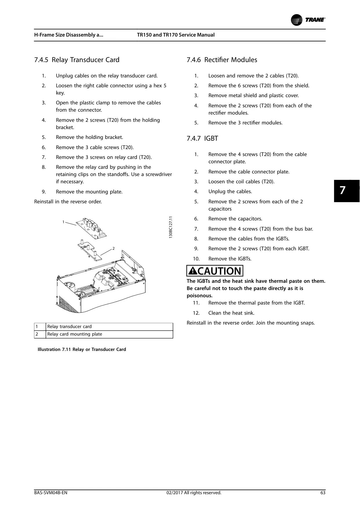
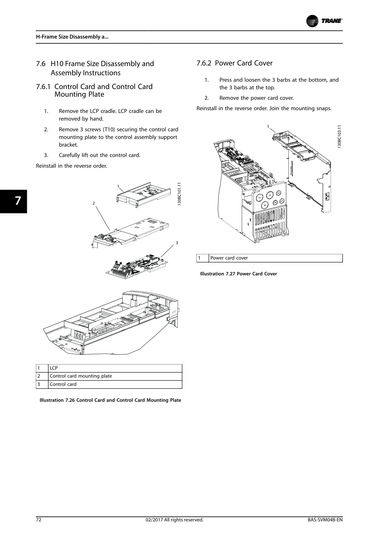
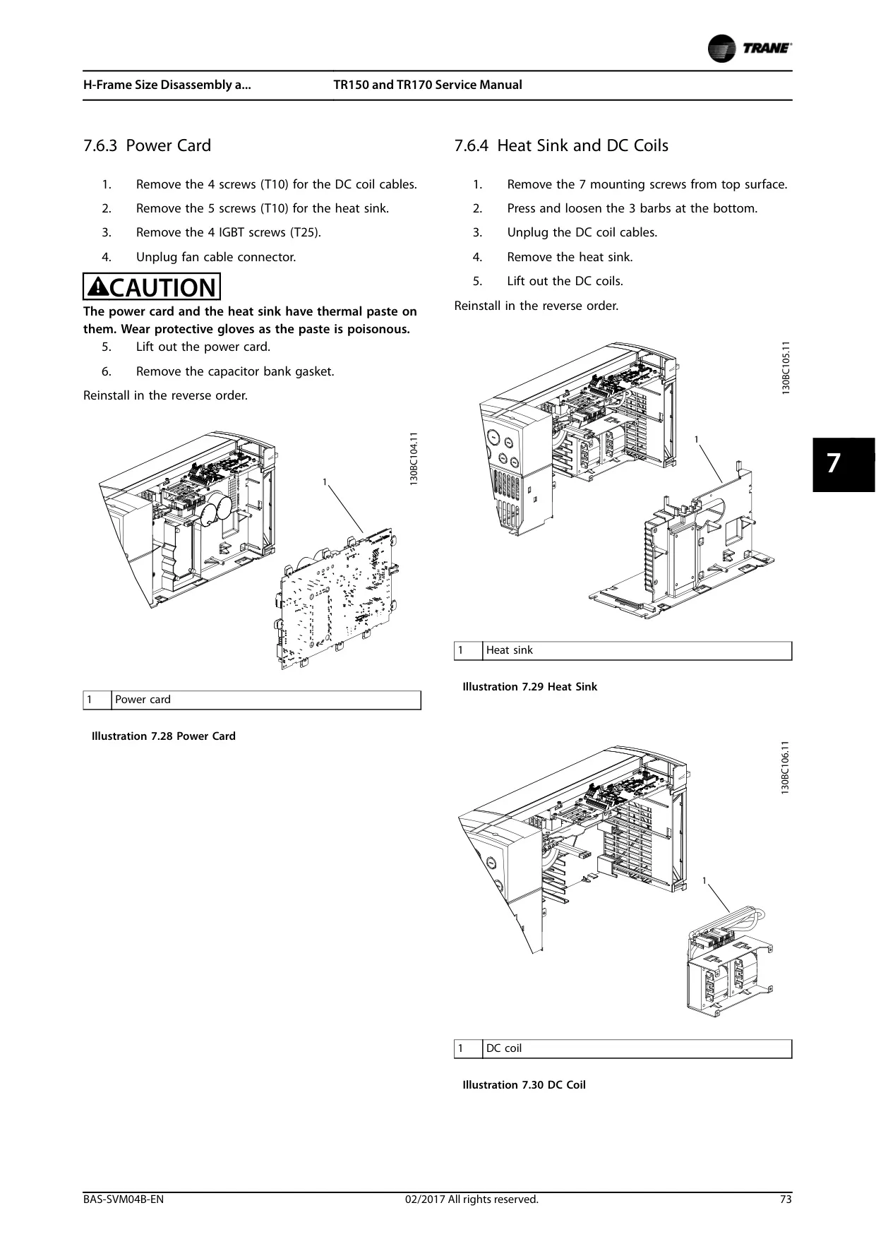
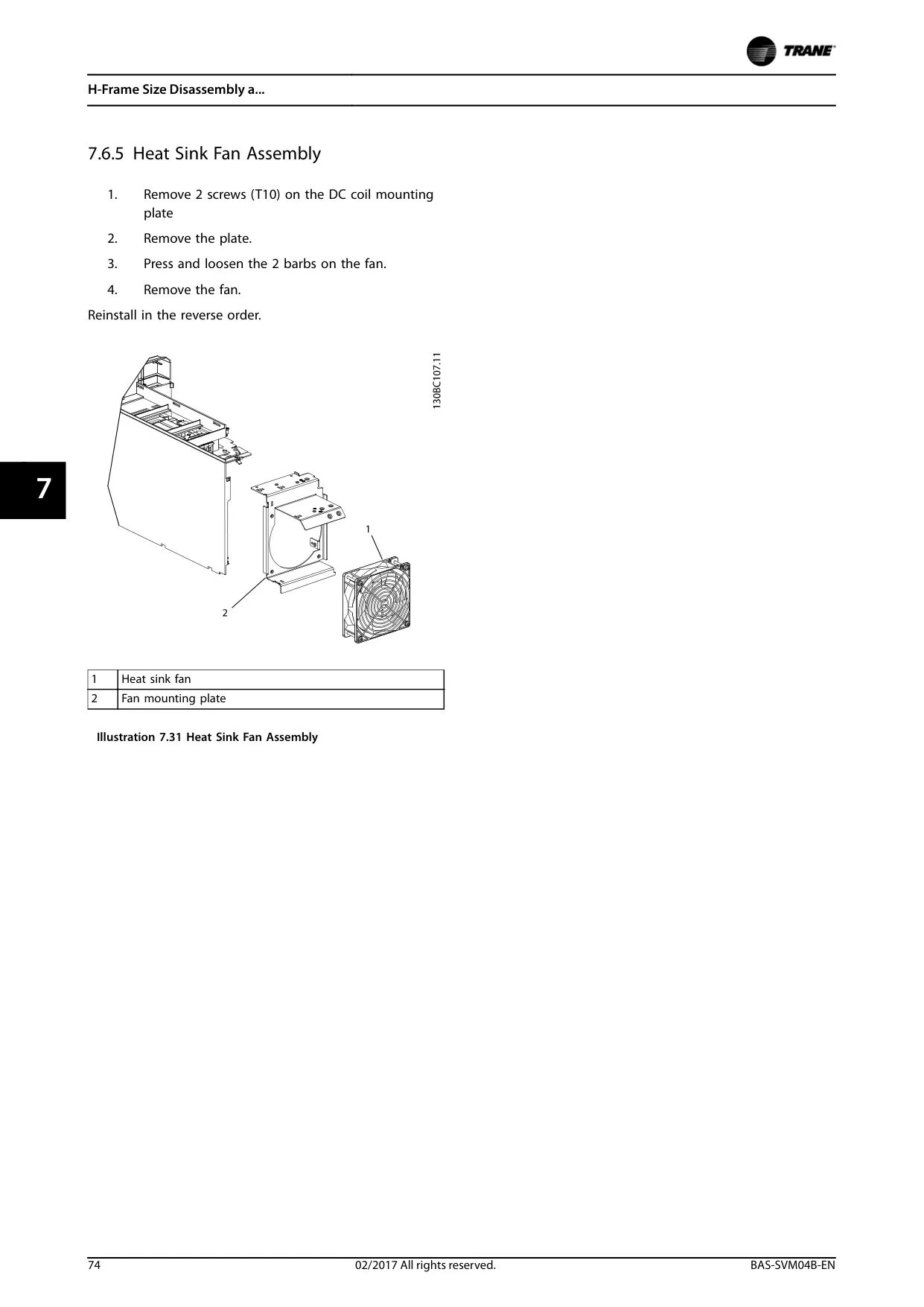
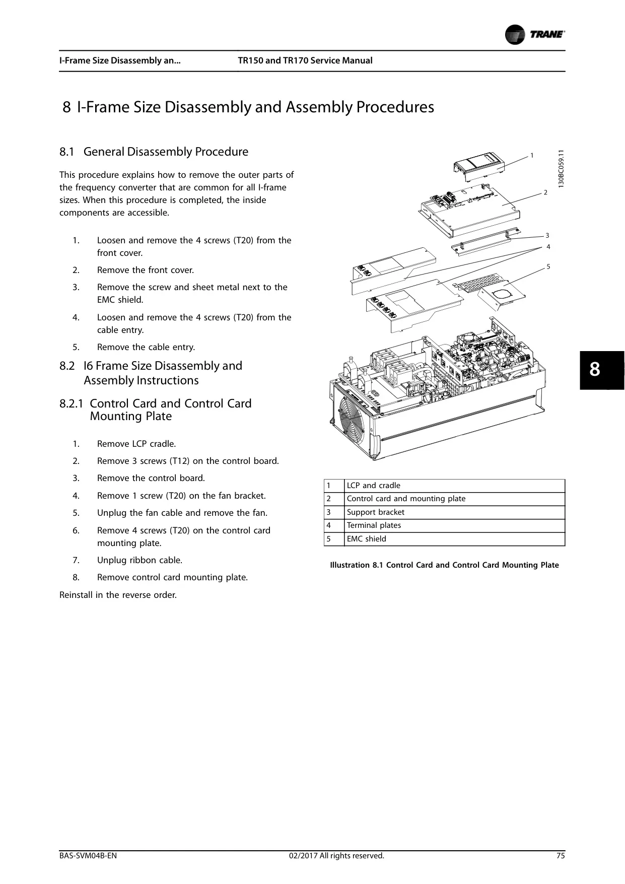
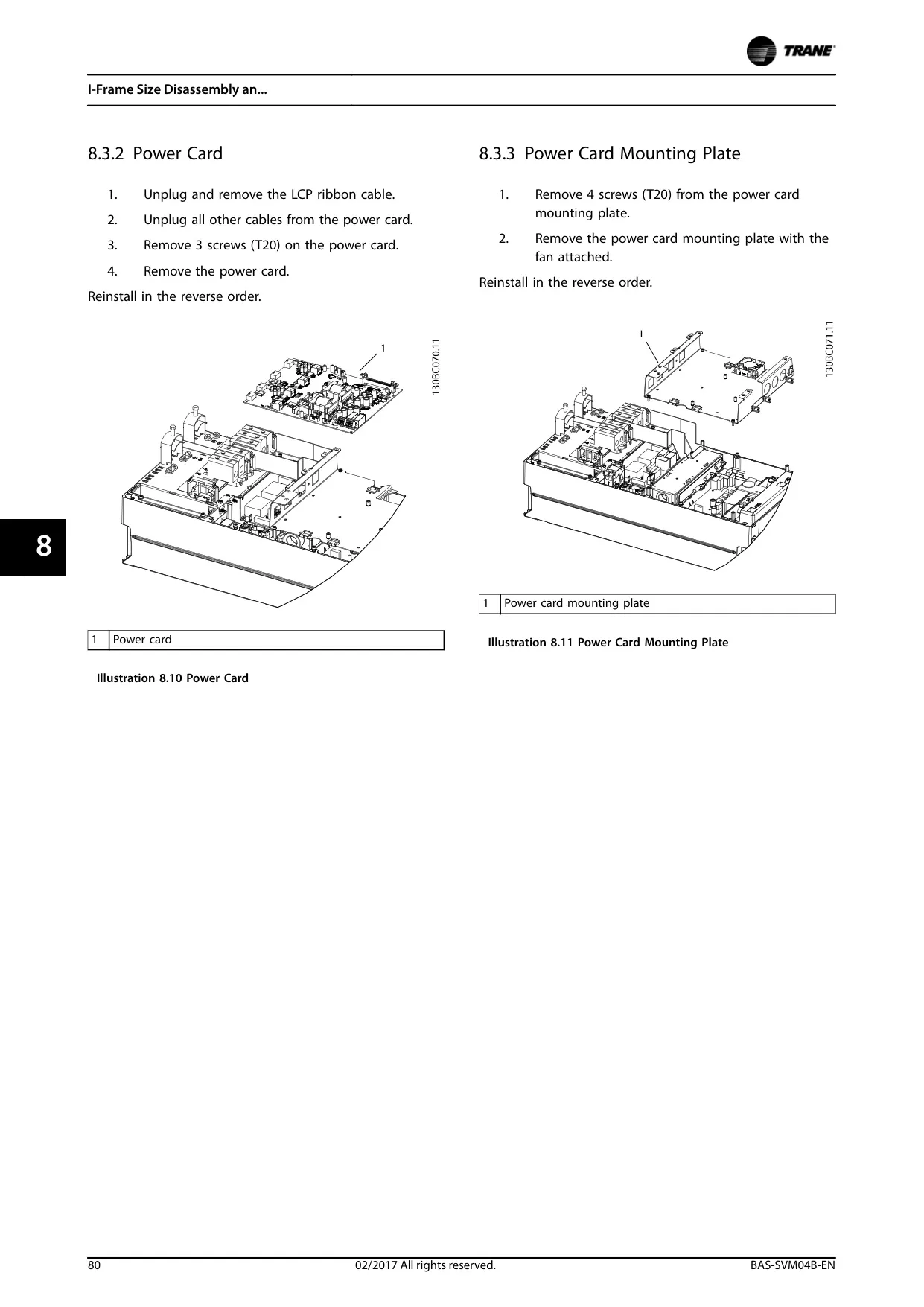
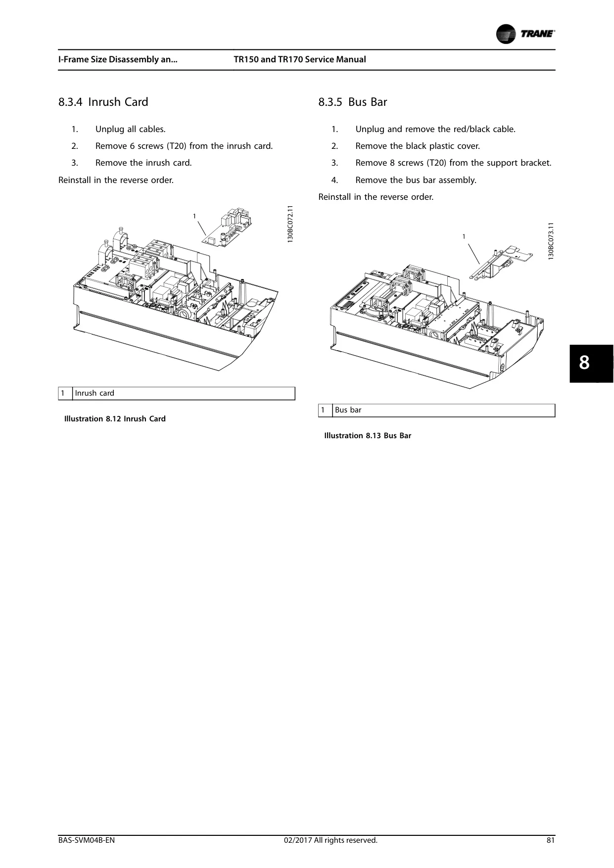
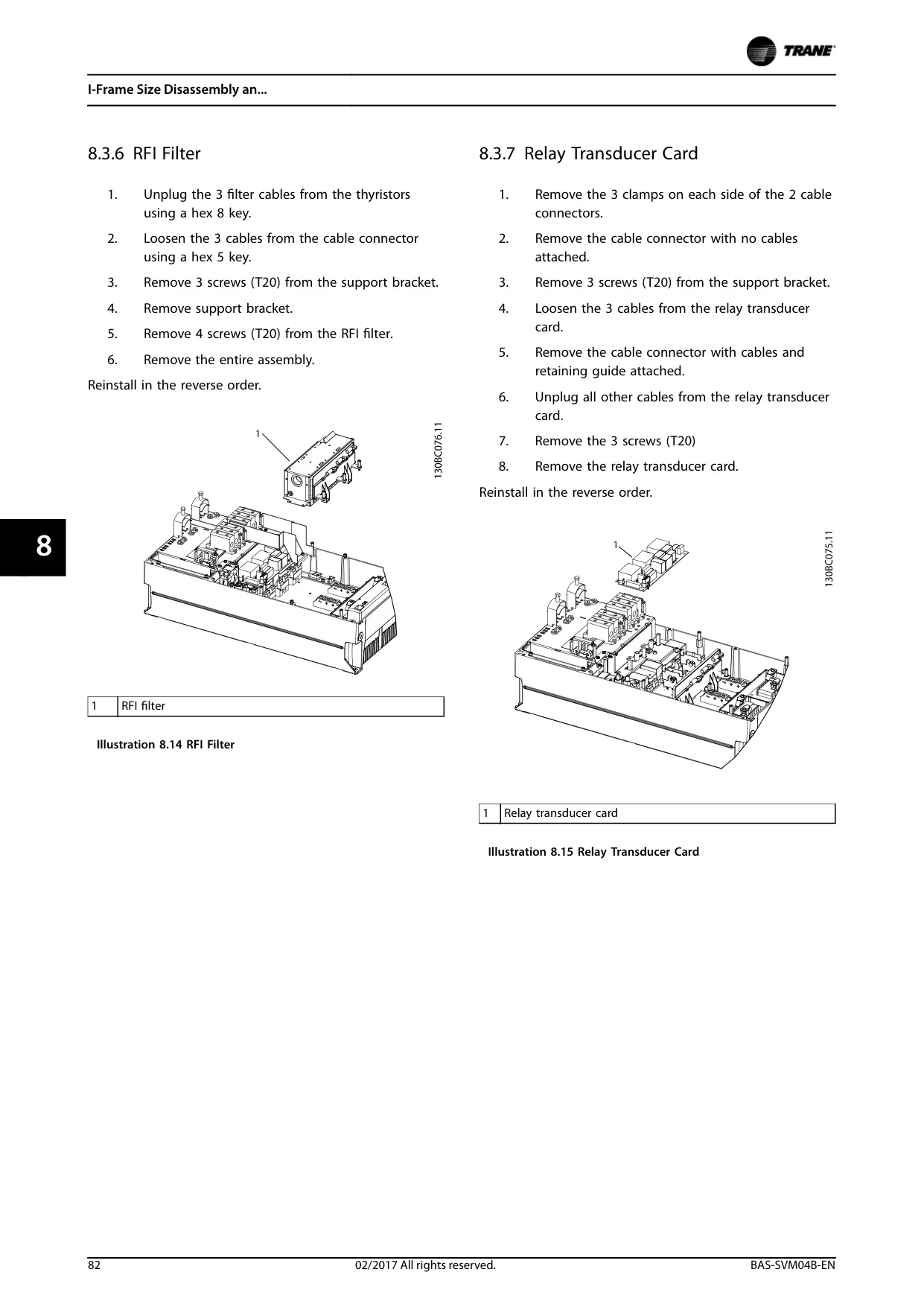
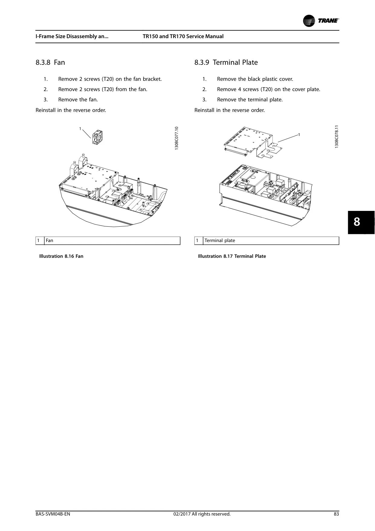
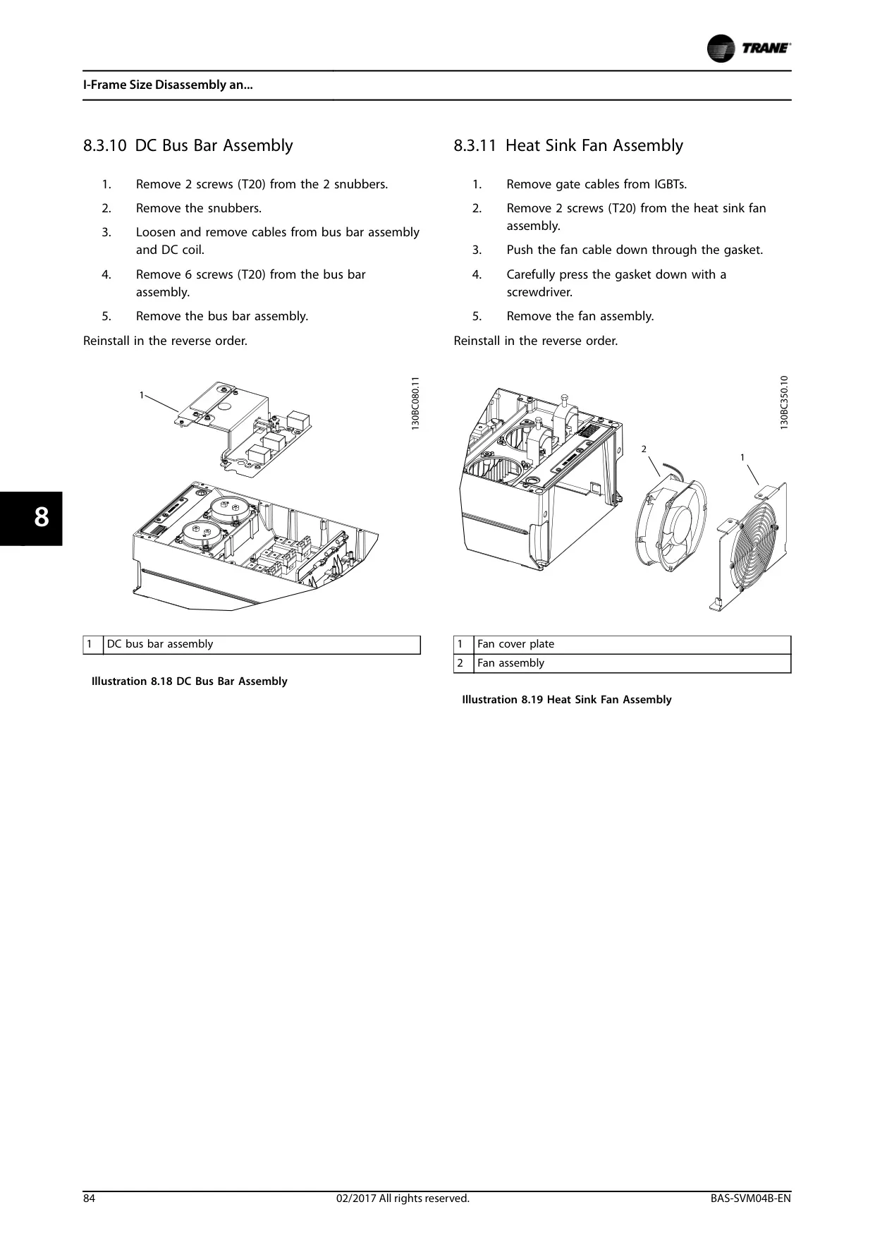
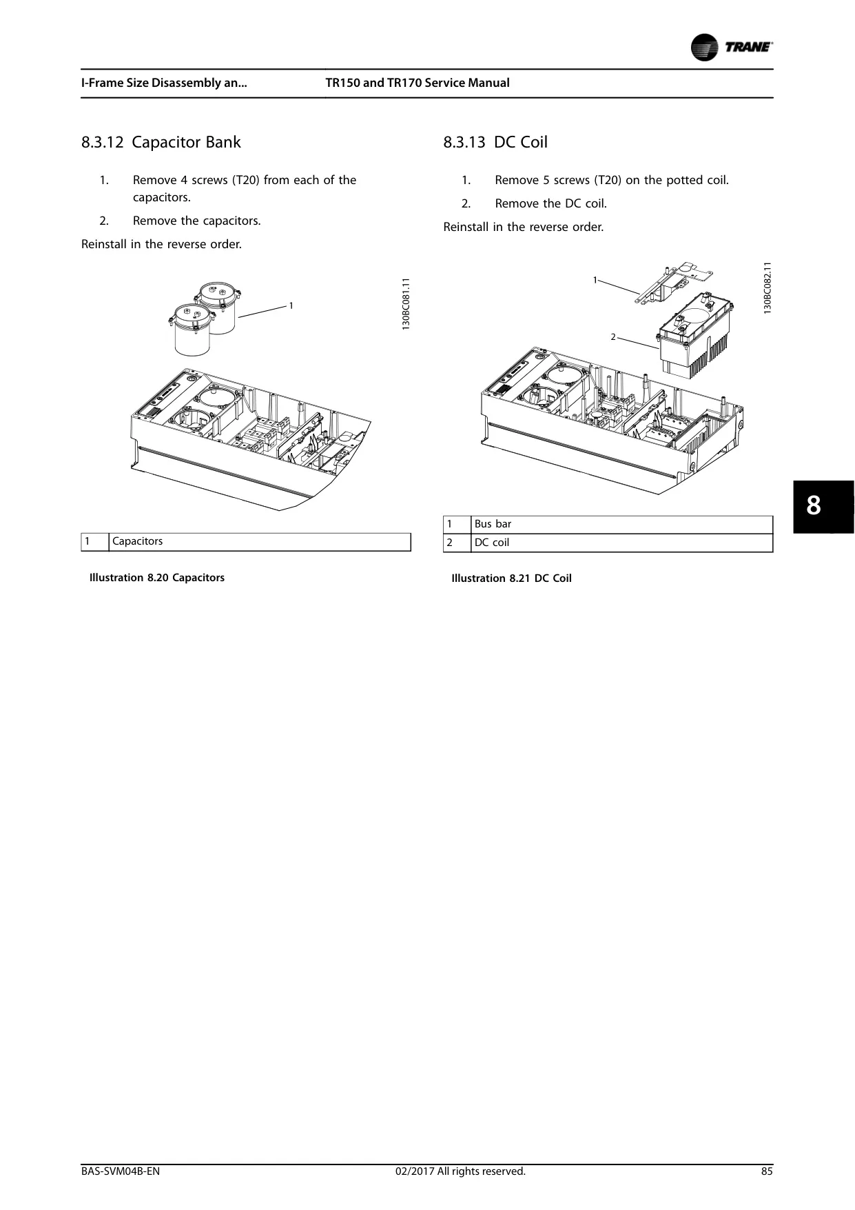
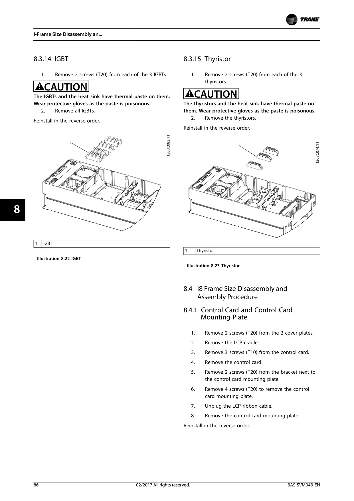
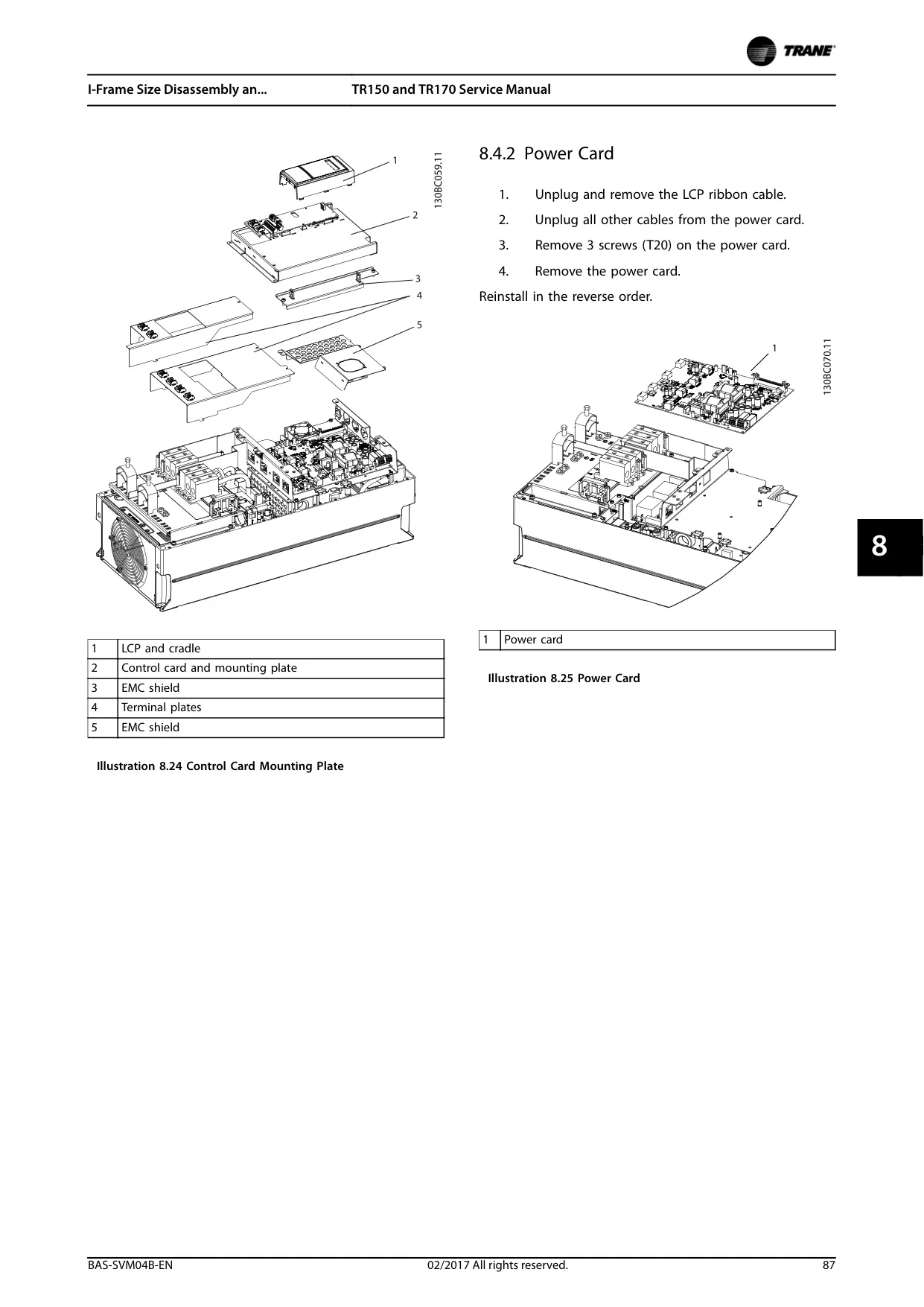
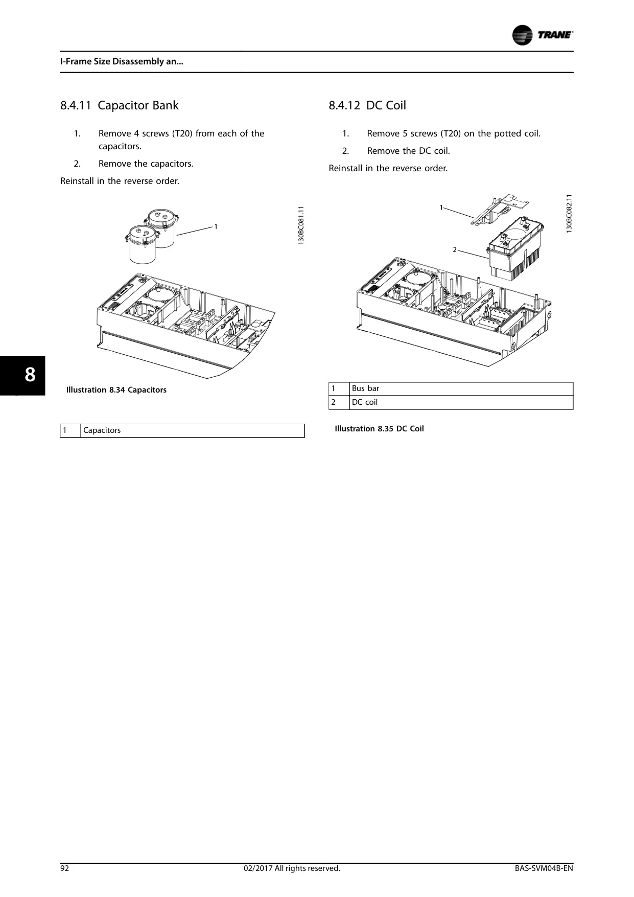
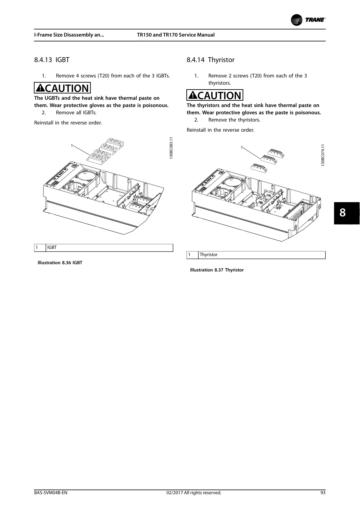
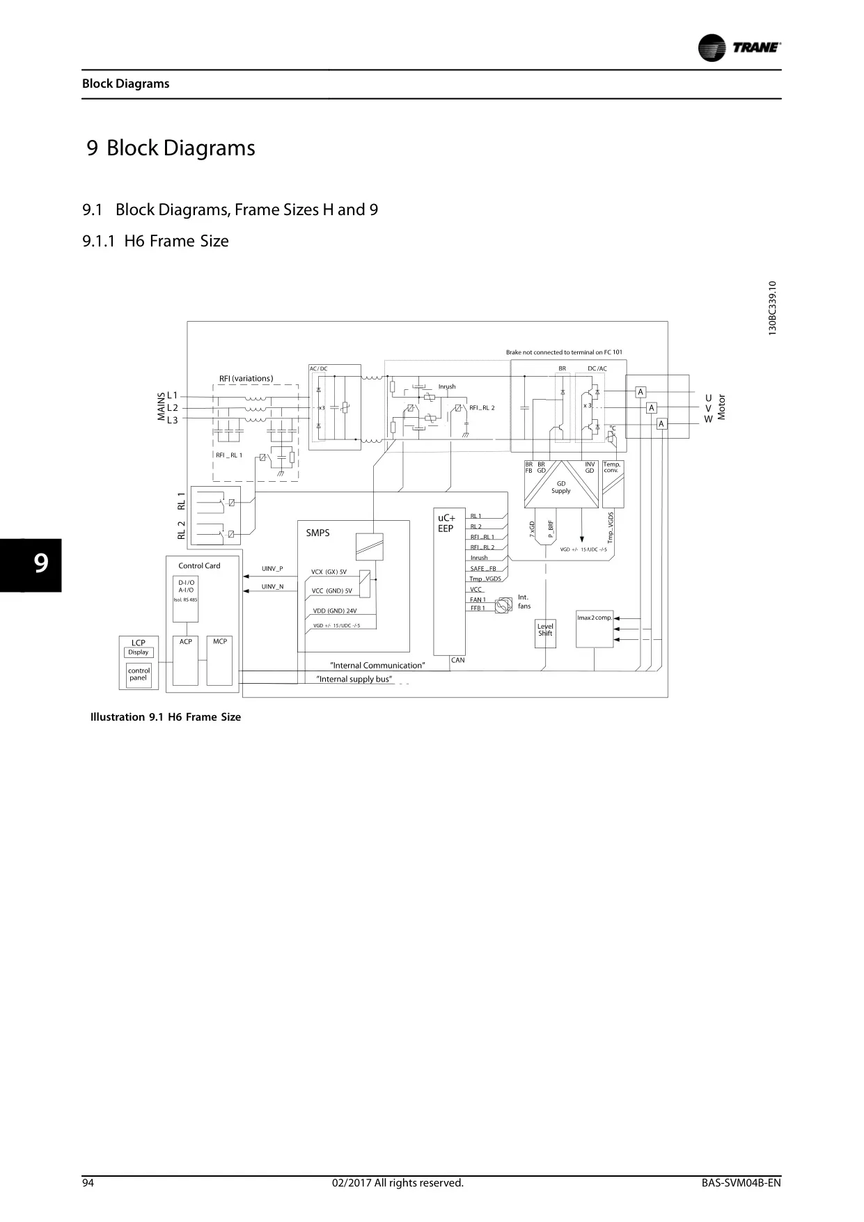
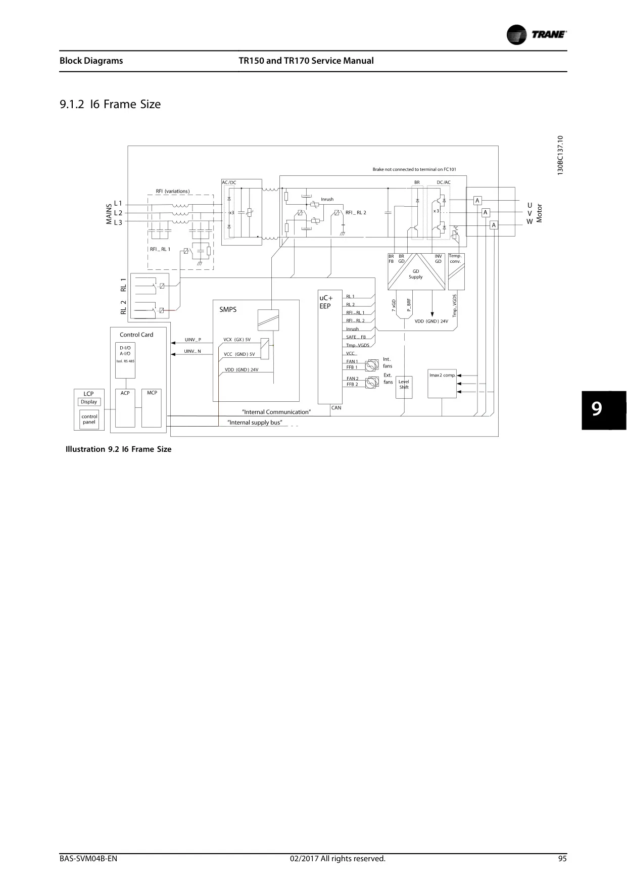
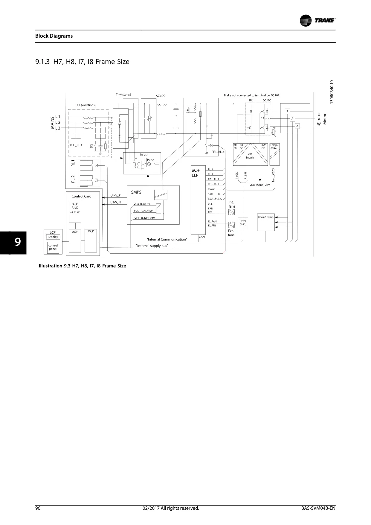
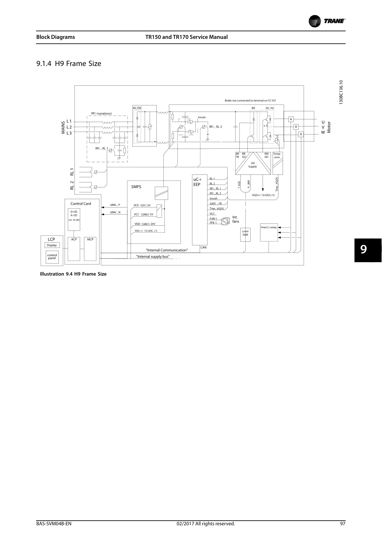
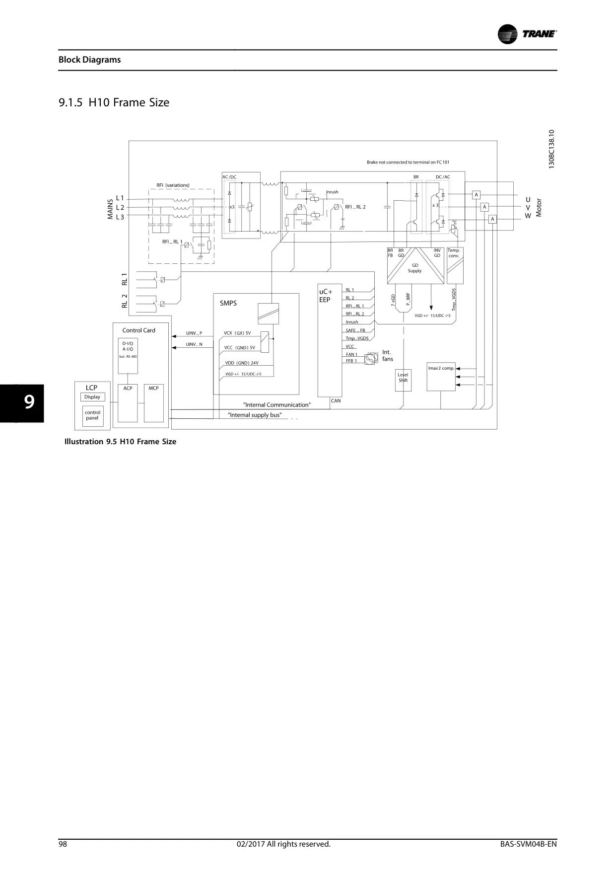
Trane TR150 VFD Instructions
Here we offer the Trane TR150 Variable Frequency Drive manual completely free and in English. We have cataloged this manual in the Variable Frequency Drives section on Manualverse, and it has been rated by 1 users with an average rating of 5. If you have any specific questions about Trane TR150 Variable Frequency Drive, we suggest checking the Frequently Asked Questions (FAQs) section of this manual.
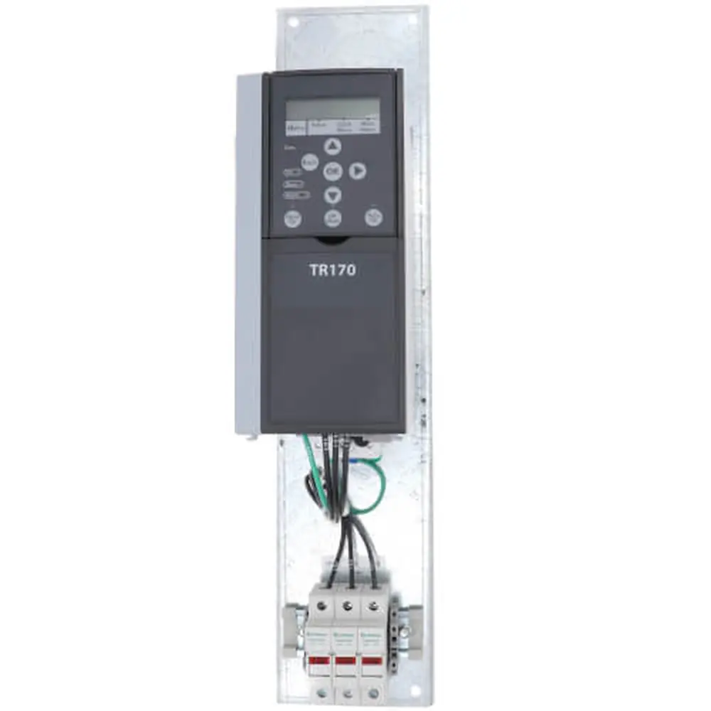
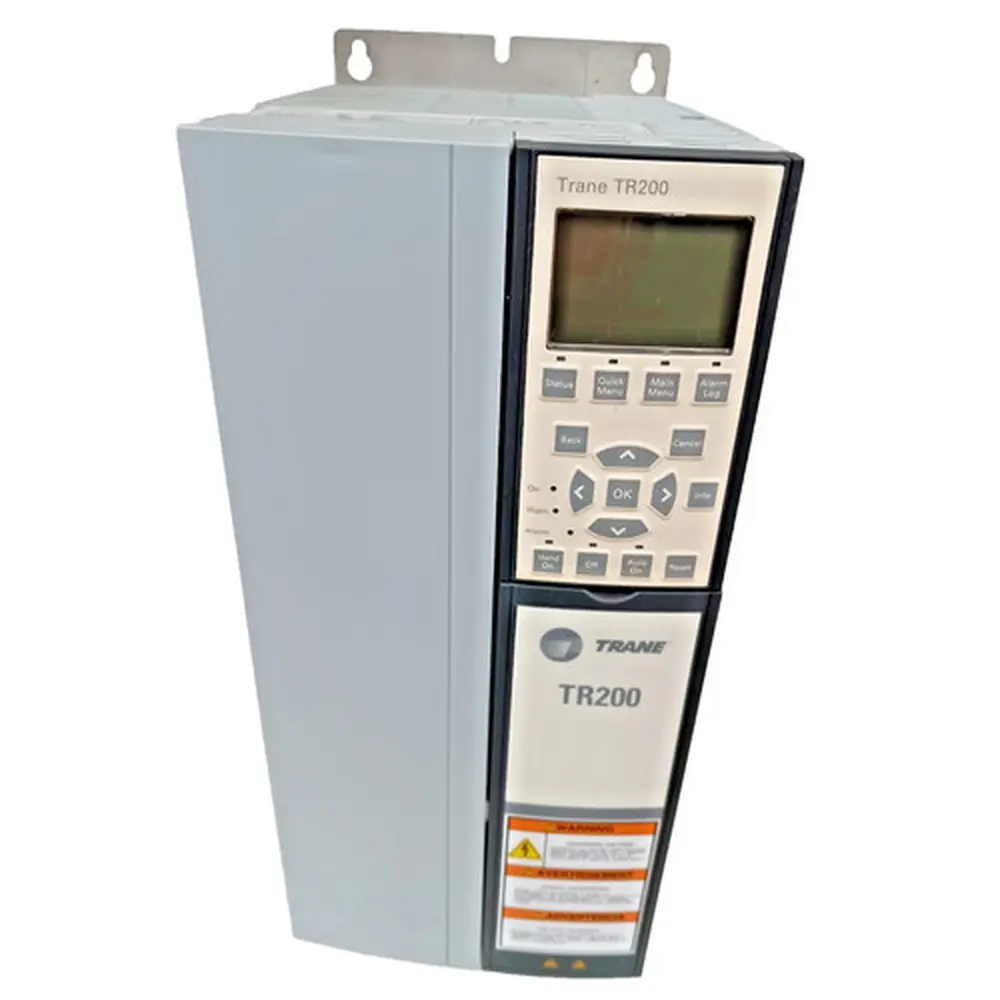
Product Images
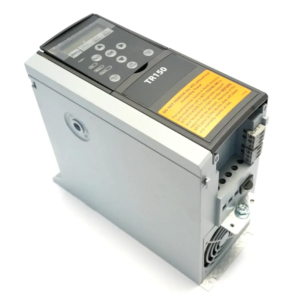


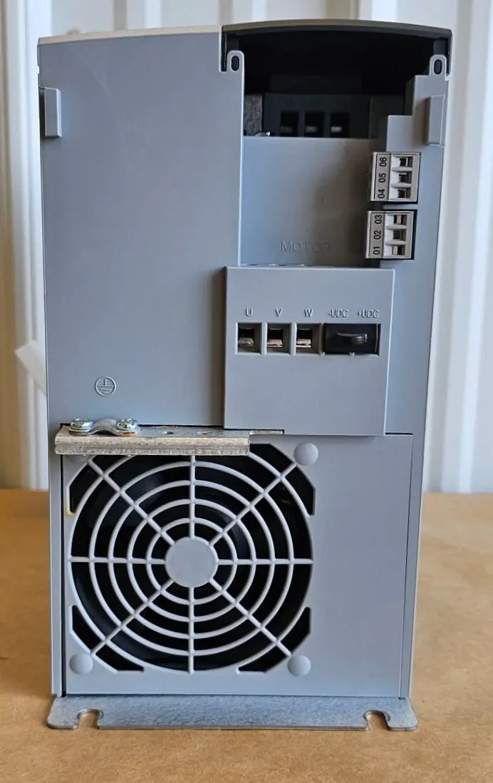
Trane TR150 Variable Frequency Drive Specifications
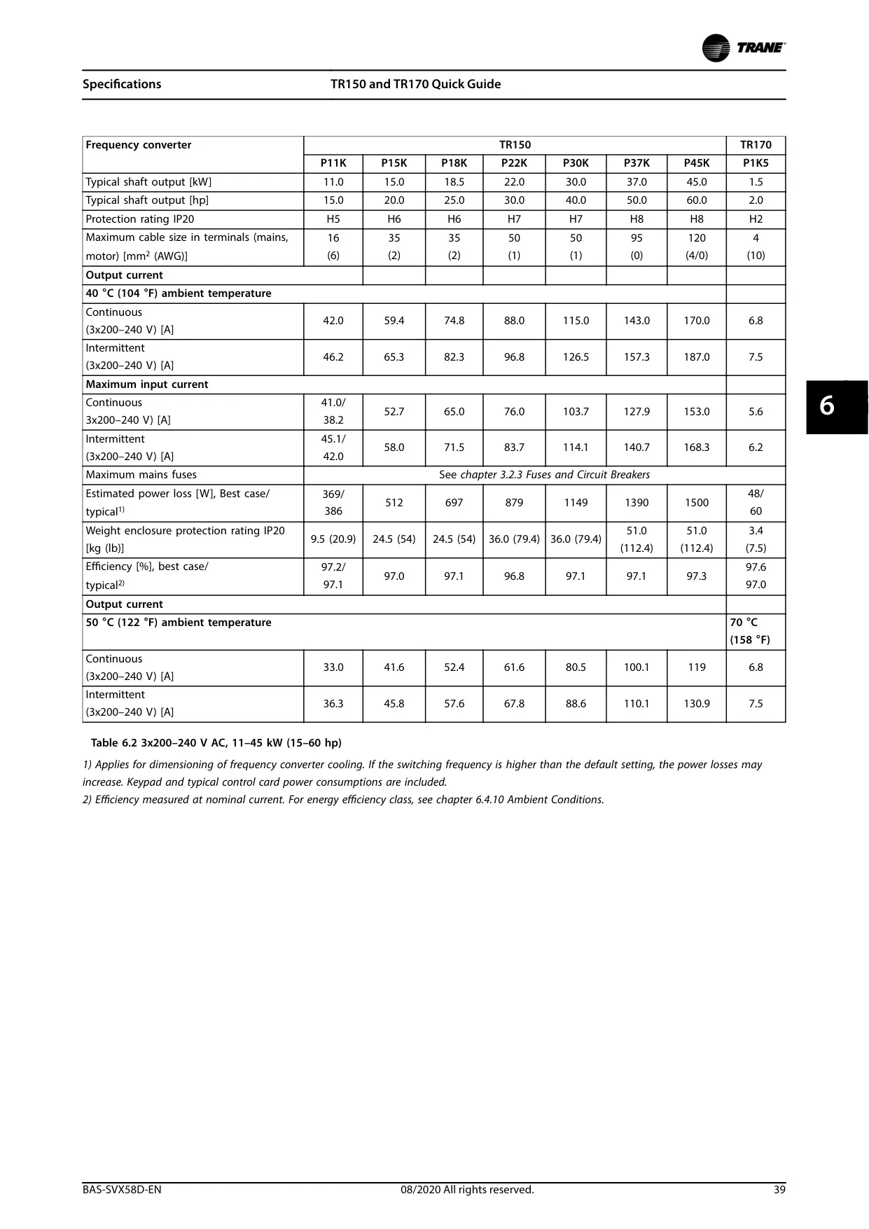
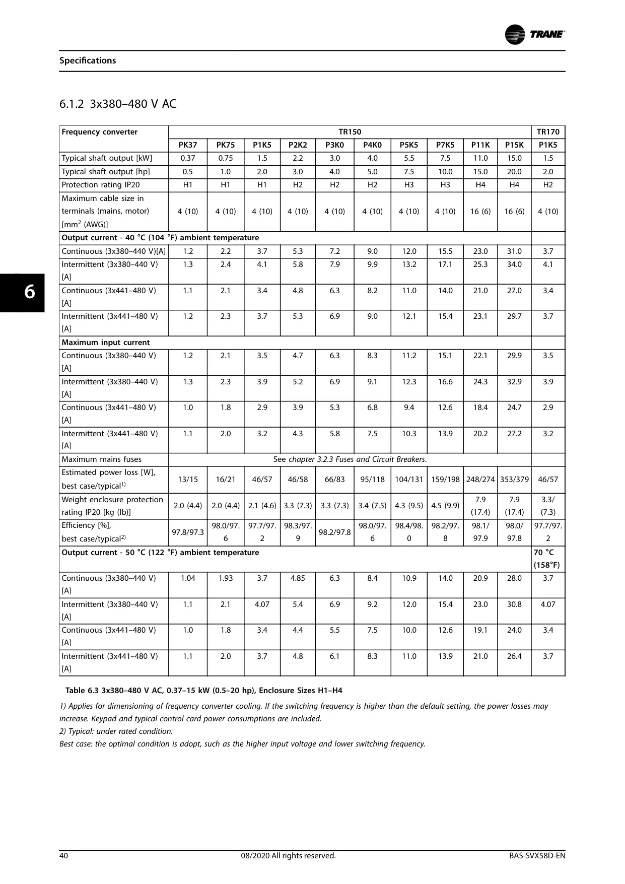
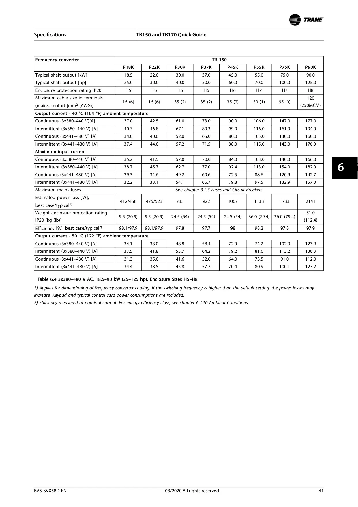
| Feature | Specification |
|---|---|
| Product Type | HVAC Variable Frequency Drive (VFD) |
| Target Audience | Qualified and Trane-approved technicians. |
| Design | Designed for the Heating, Ventilation, and Air Conditioning (HVAC) market. Operates in variable torque mode, with specific features for fan and pump applications. |
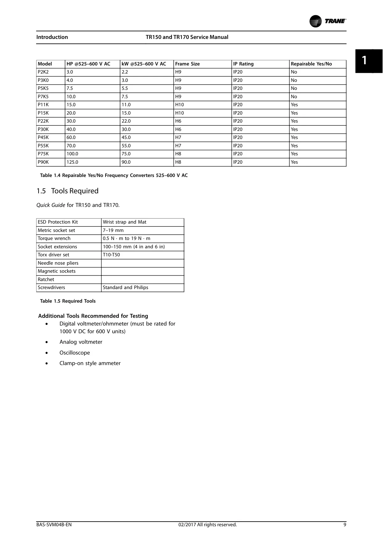
| Supply Voltage (Three-Phase) | 200–240 V AC, 380–480 V AC, 525–600 V AC |
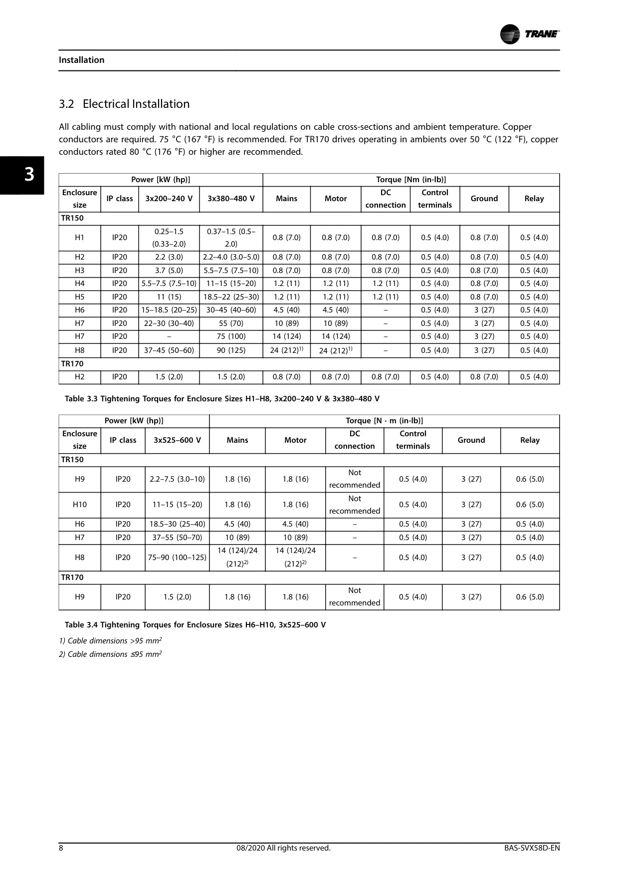
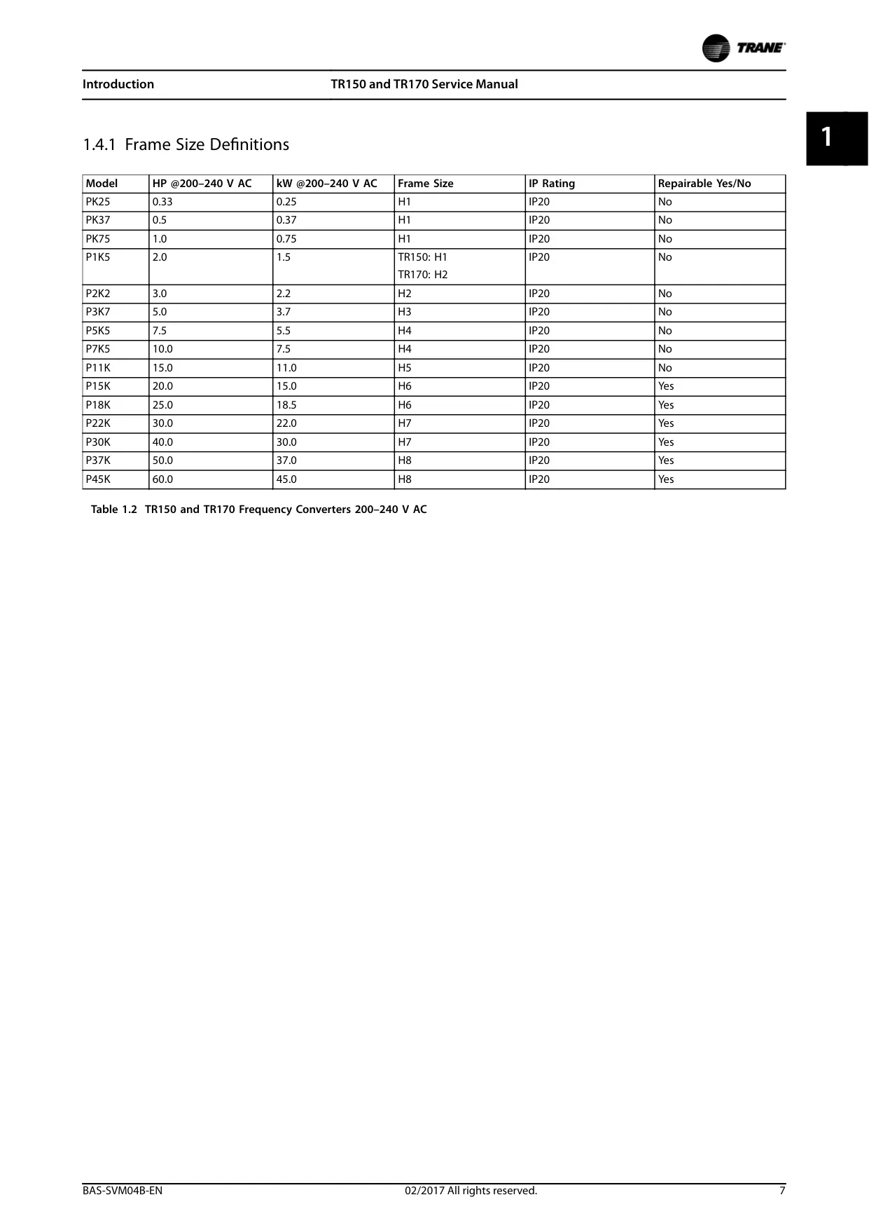
| Power Range | 0.25 kW (0.33 HP) to 90 kW (125 HP) (Varies depending on model and voltage) |
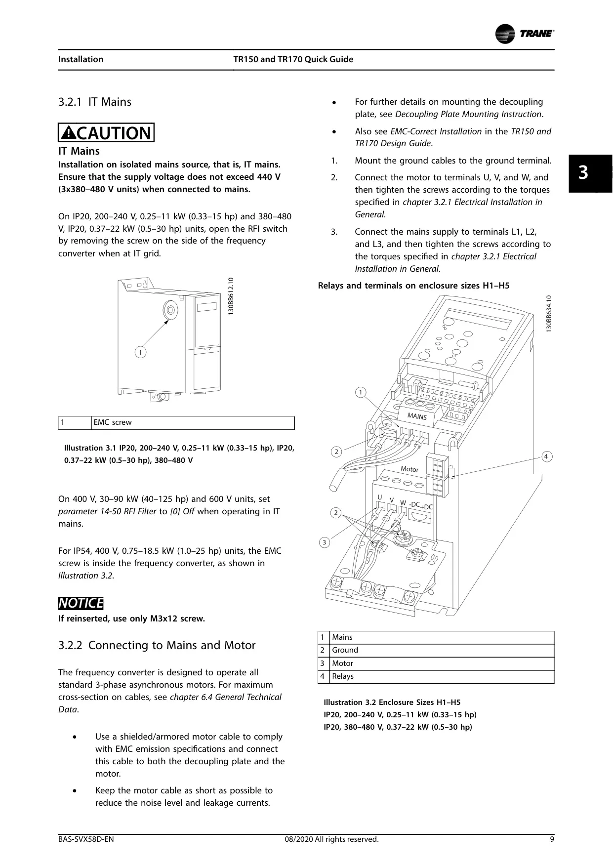
| IP Rating | IP20 (H-Frame), IP54 (I-Frame) |
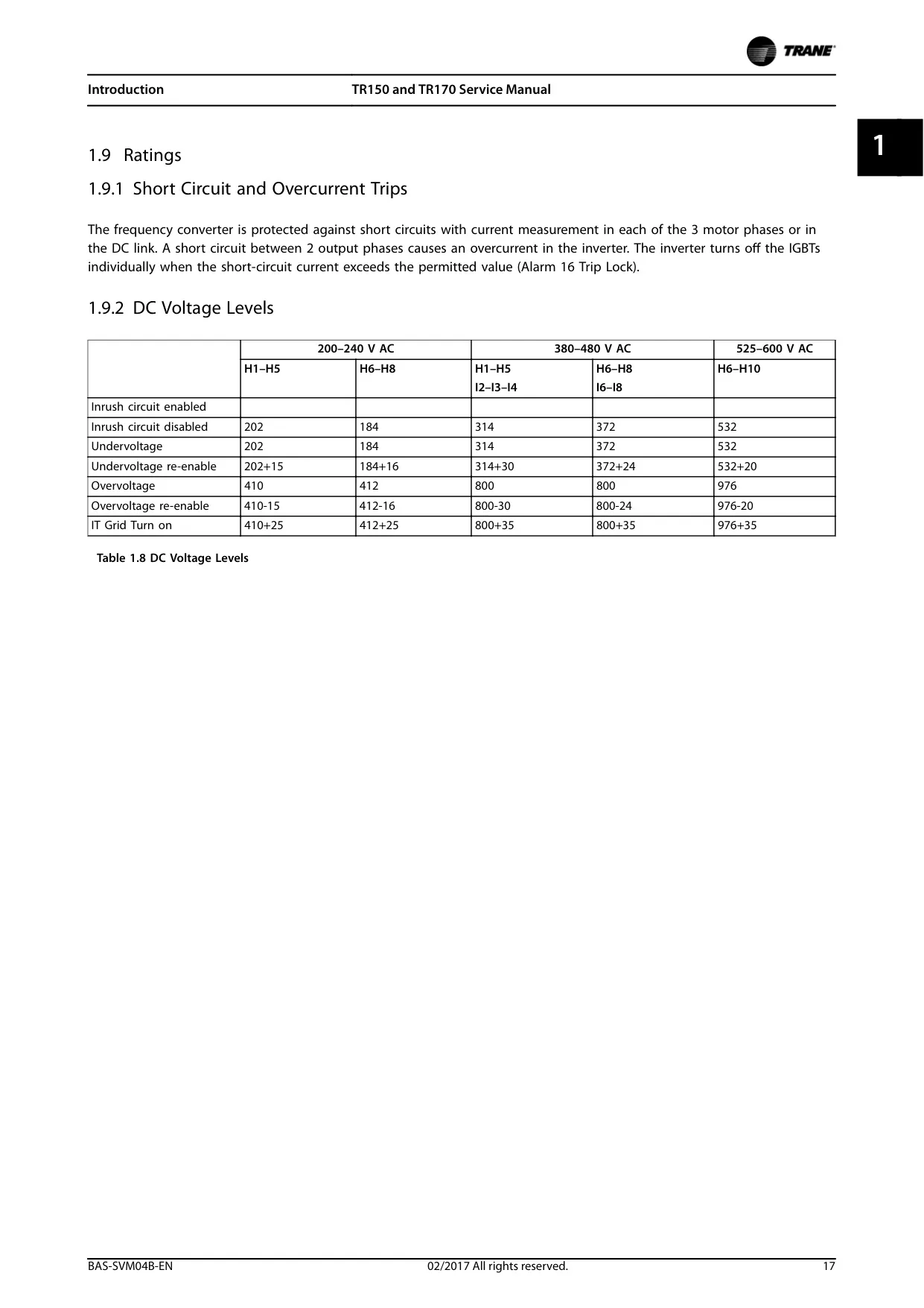
| DC Voltage Levels (Intermediate Circuit) | 200-240 V AC: Undervoltage (184-202 V DC), Overvoltage (410-412 V DC) 380-480 V AC: Undervoltage (314-372 V DC), Overvoltage (800 V DC) 525-600 V AC: Undervoltage (532 V DC), Overvoltage (976 V DC) |
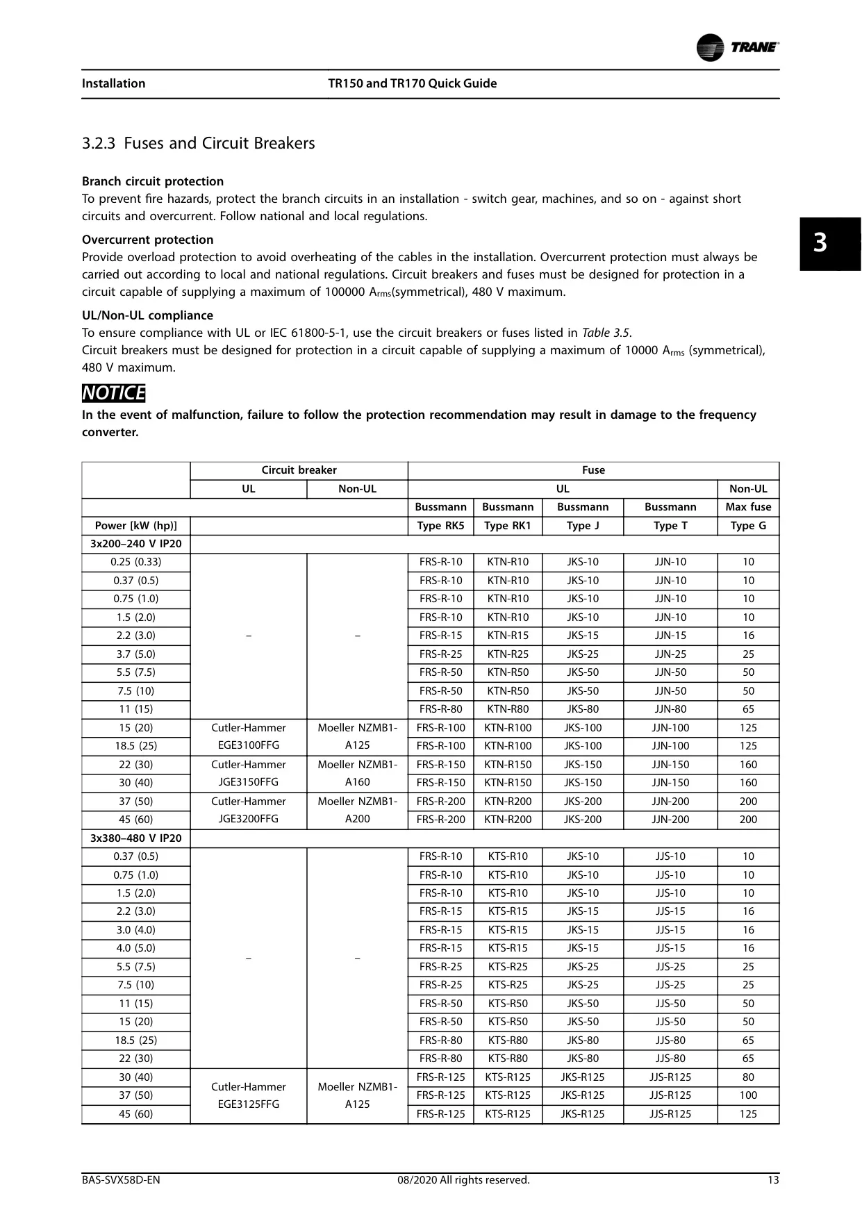
| Protection | Short-circuit and overcurrent (measurement on all 3 motor phases or in the DC link, individual shut-off of IGBTs - Alarm 16 Trip Lock). |
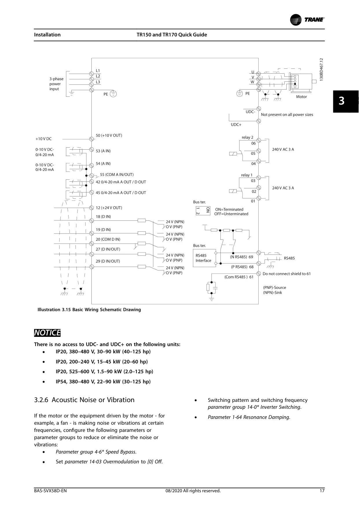
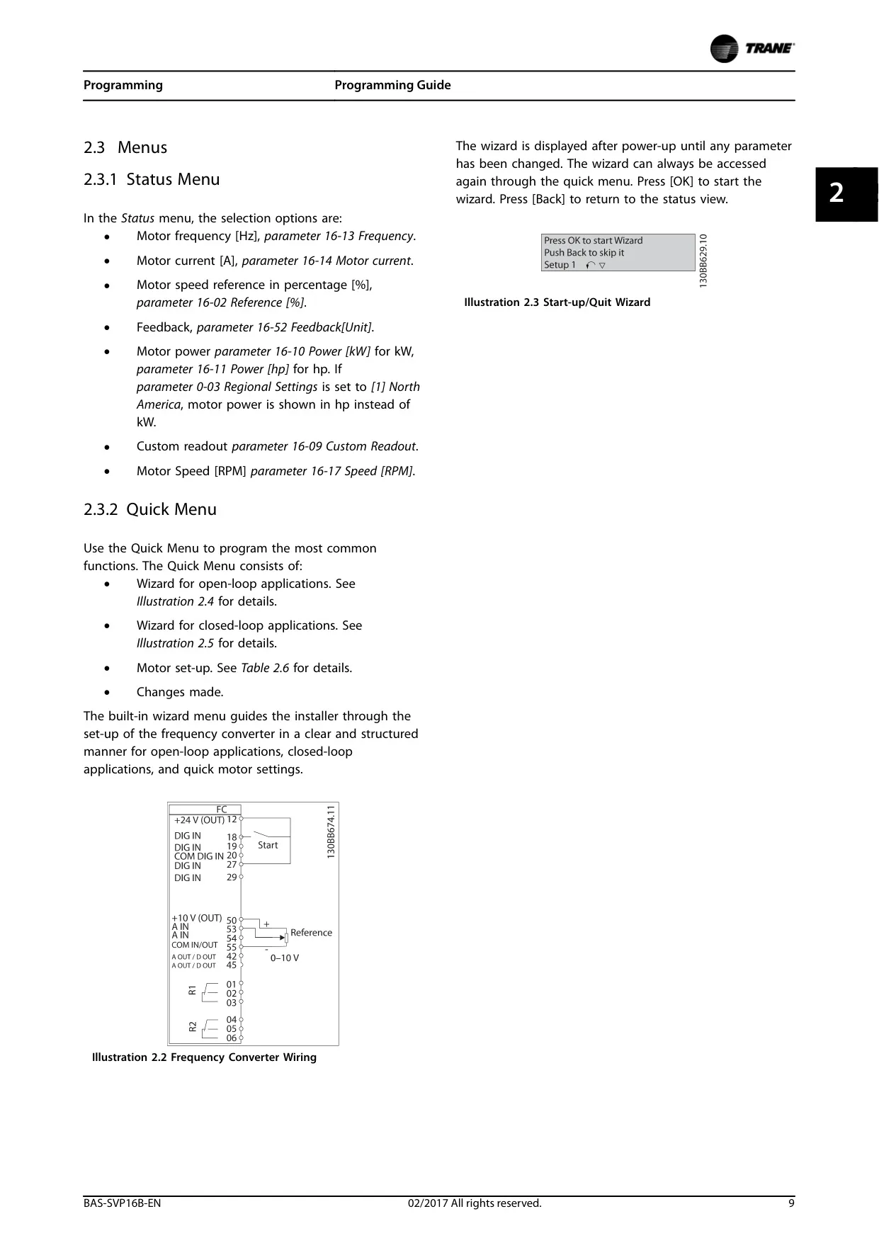
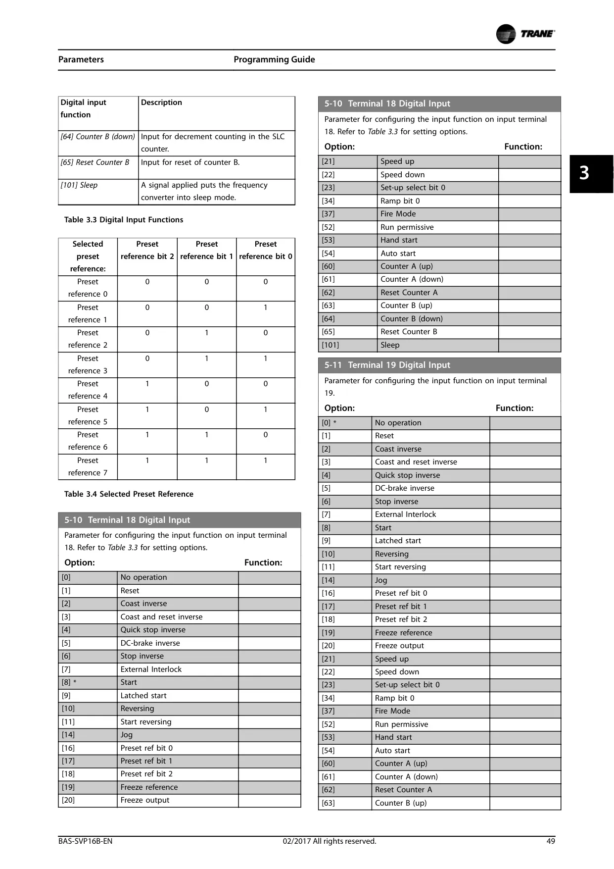
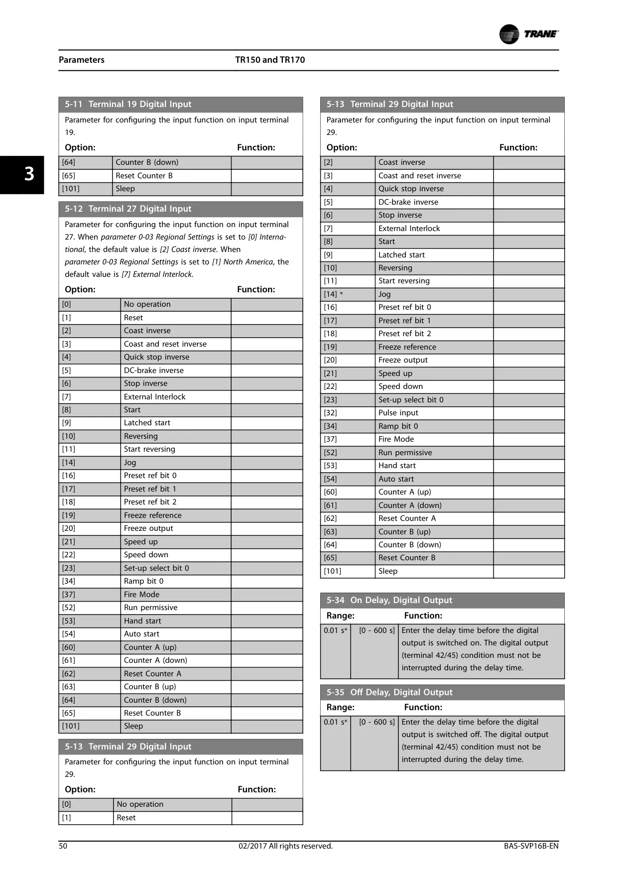
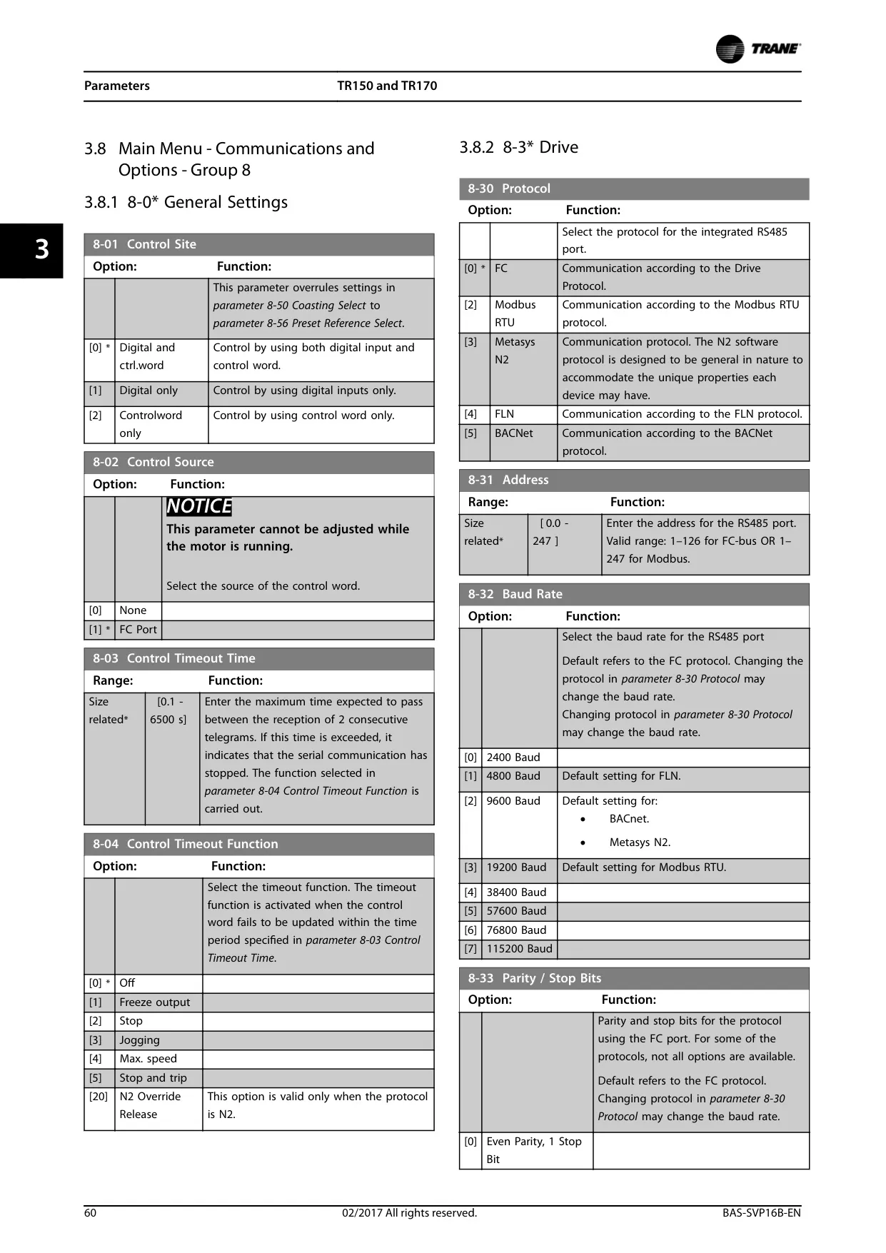
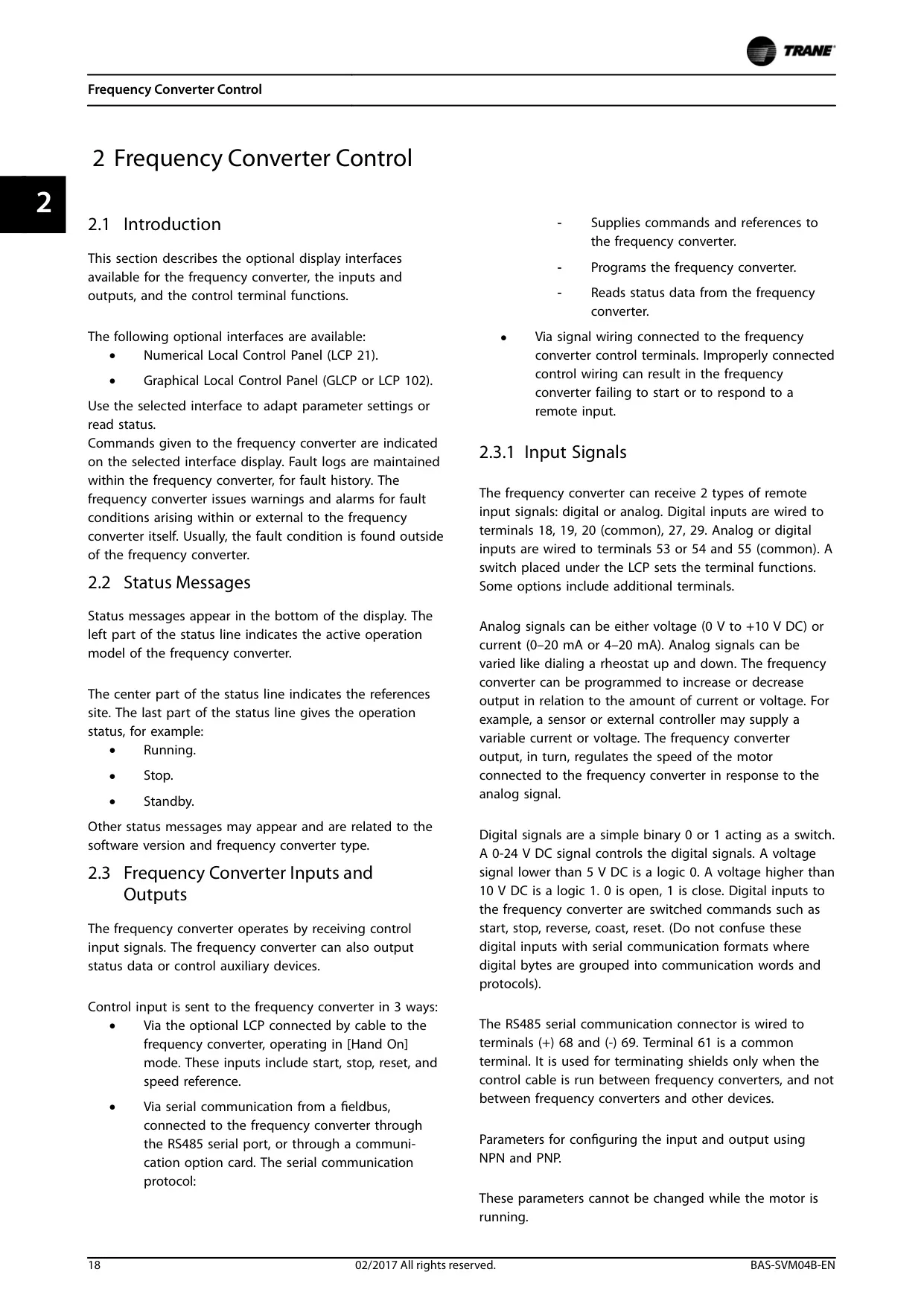
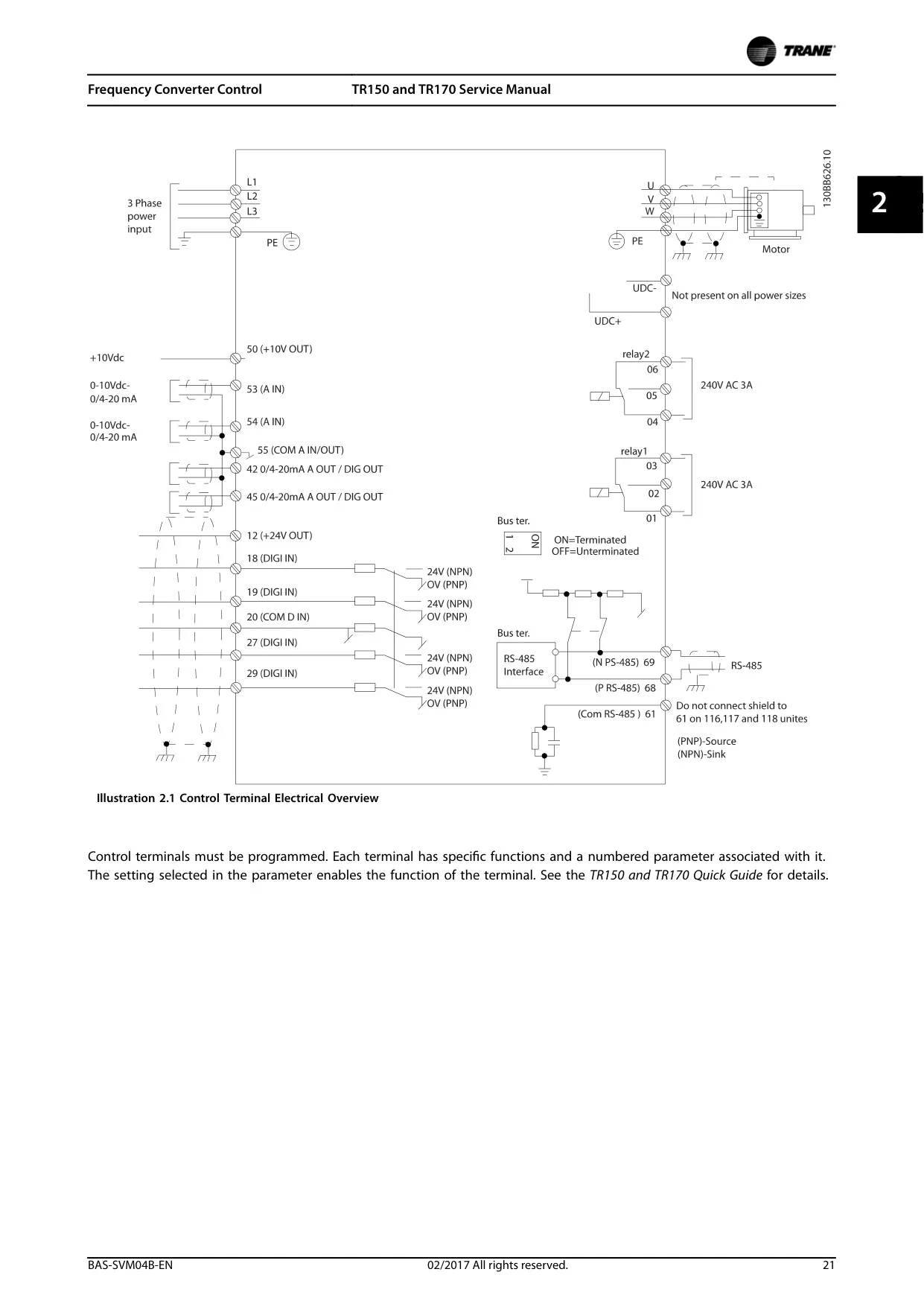
| Signal Inputs | 2 analog inputs (0-10 V DC or 0/4-20 mA) on terminals 53 and 54. 5 digital inputs (0-24 V DC) on terminals 18, 19, 20 (common), 27, 29. RS485 interface for serial communication (terminals (+) 68 and (-) 69). |
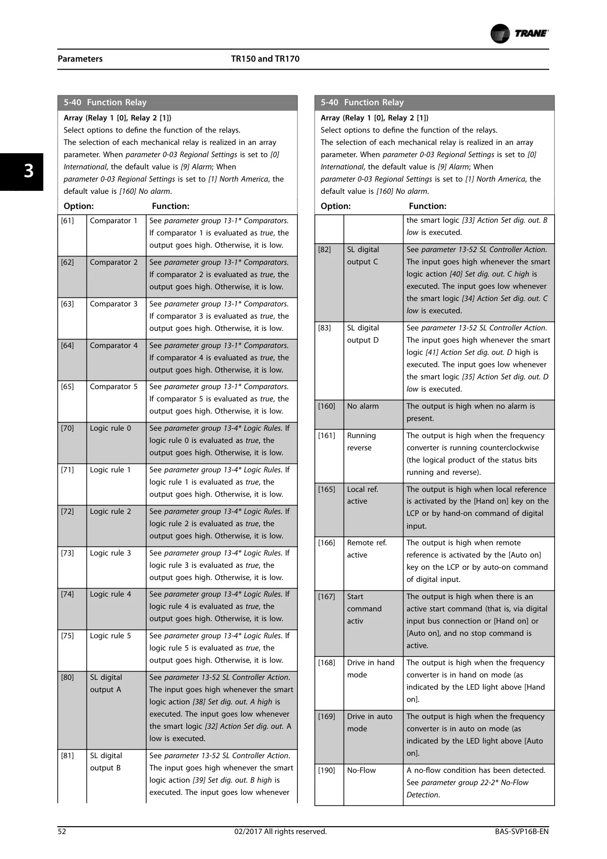
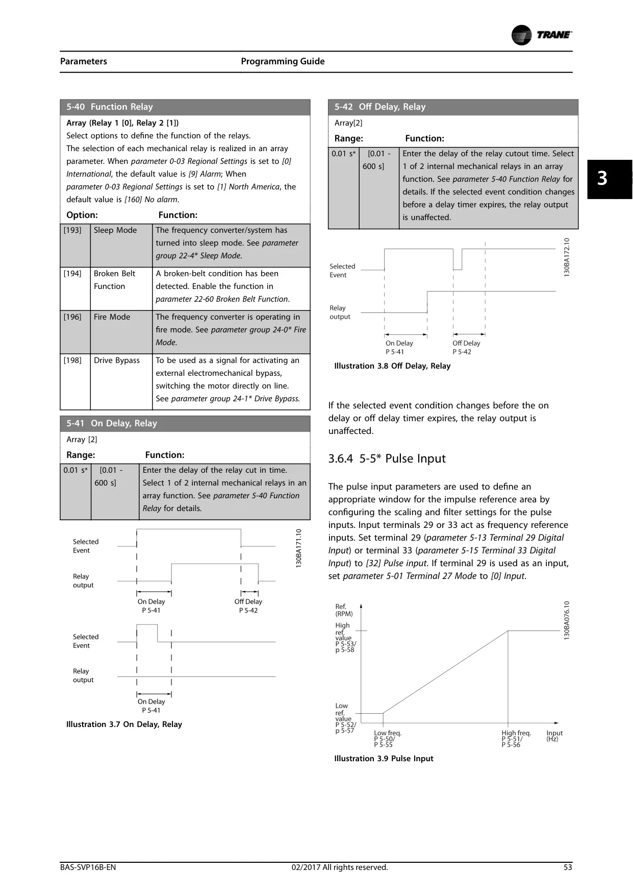
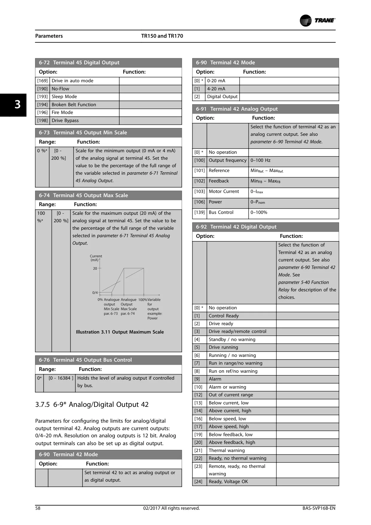
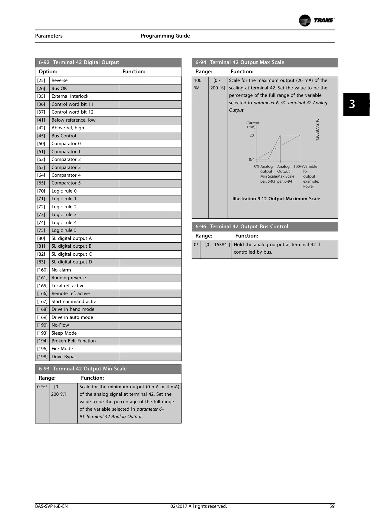
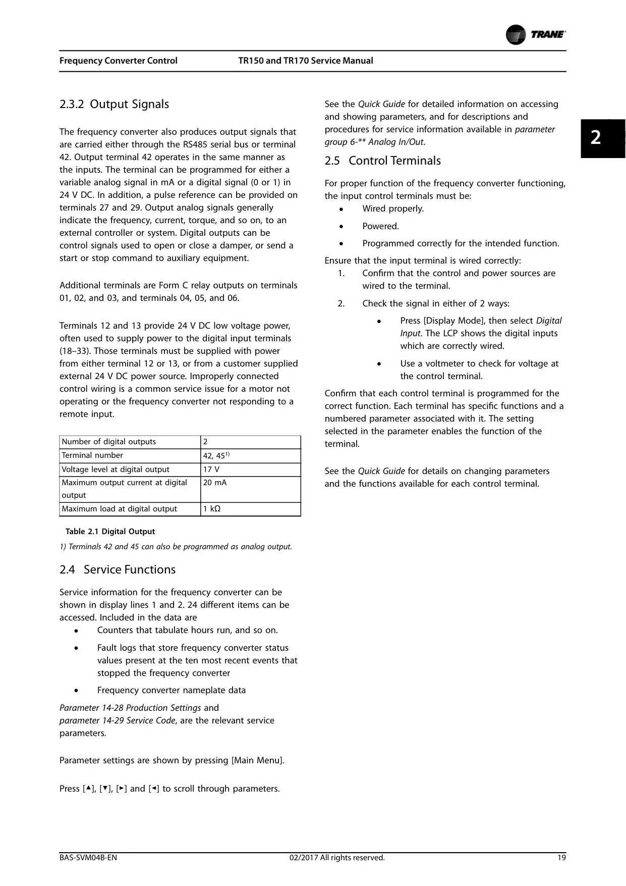
| Signal Outputs | 2 programmable digital (17 V, 20 mA max.) or analog (0/4-20 mA) outputs on terminals 42, 45. Form C relay outputs (01, 02, 03) and Form A (04, 05). |
| Control Voltage Supply | 24 V DC (max. 200 mA) on terminals 12, 13. 10 V DC (max. 17 mA) on terminal 50. |
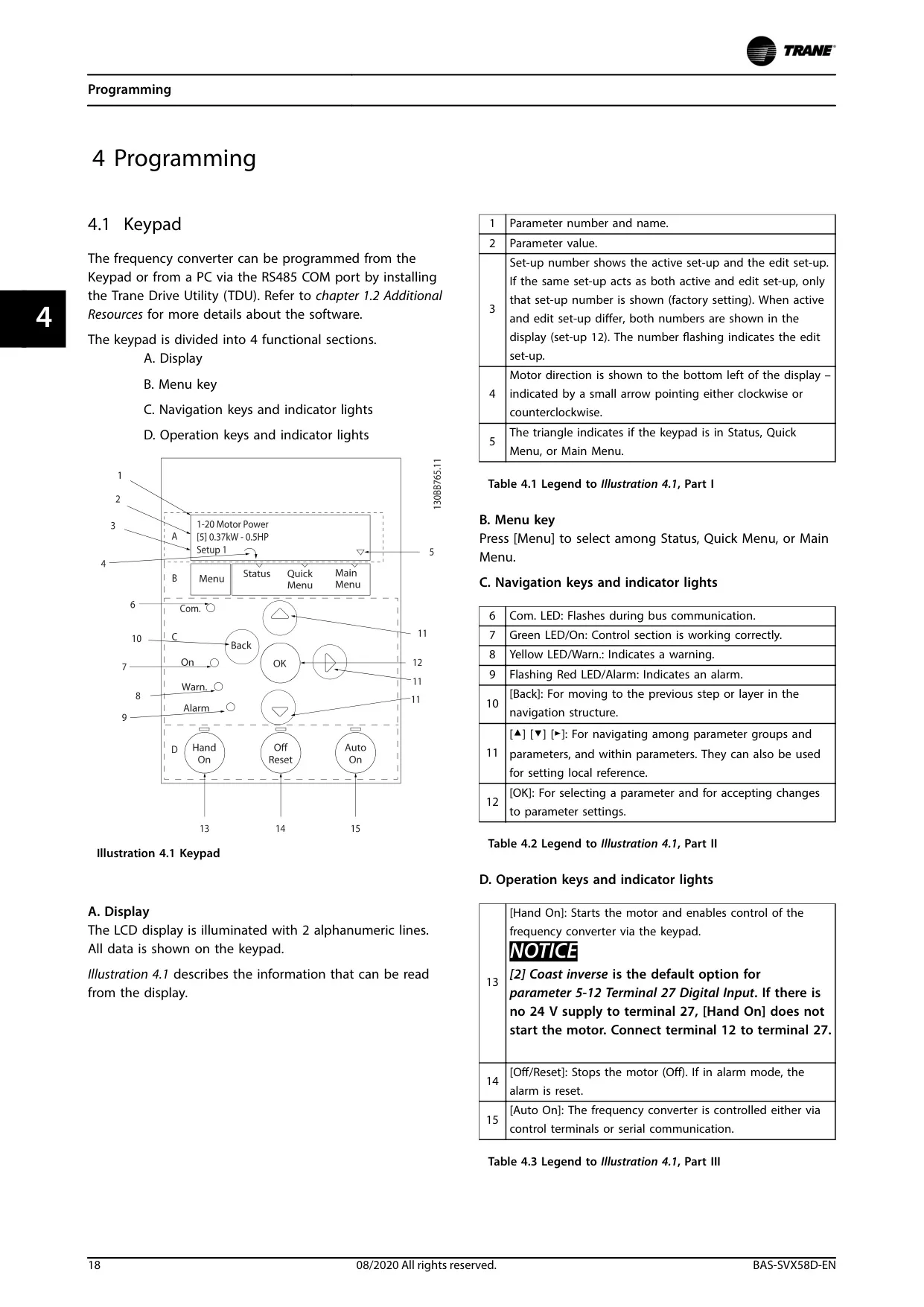
| User Interface | Optional numerical (LCP 21) or graphical (GLCP or LCP 102) Local Control Panel (LCP). |
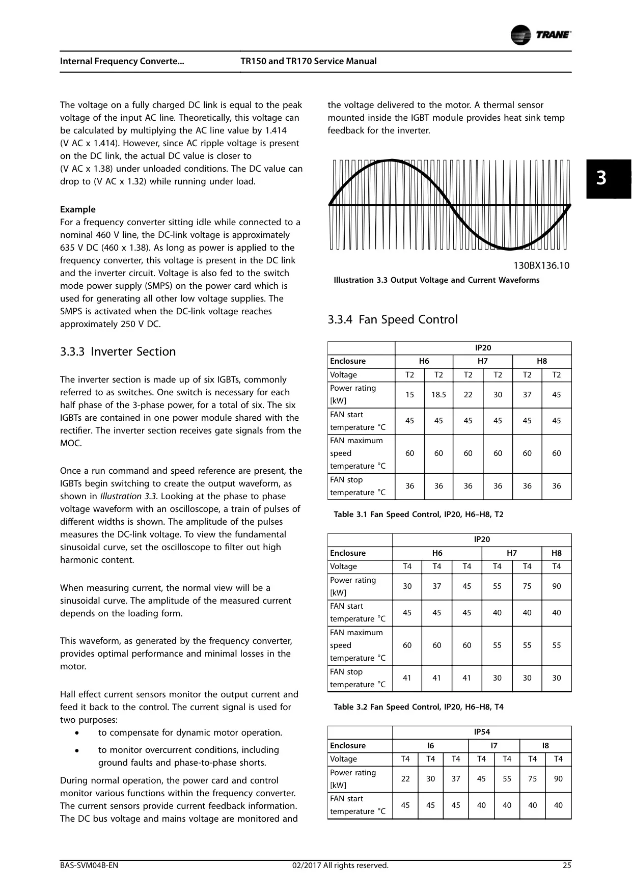
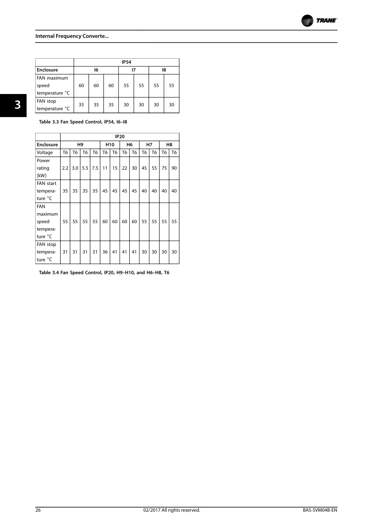
| Fan Speed Control | Controlled by heatsink temperature (e.g., Start at 35-45 °C, maximum speed at 55-60 °C, stop at 30-41 °C, varies by model). |
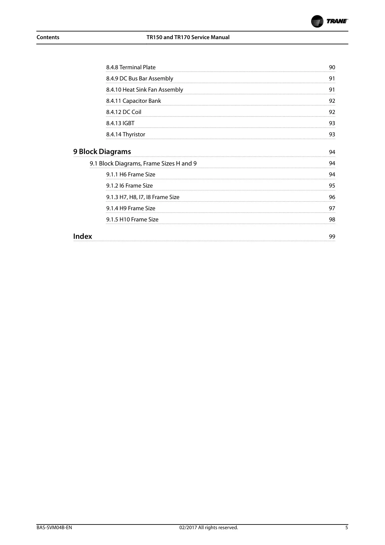
| Repairability | Frame sizes H1-H5 and I2-I5 models are Non-Repairable. Frame sizes H6-H8, H10, and I6-I8 models are Repairable. |
Trane TR150 VFD Details
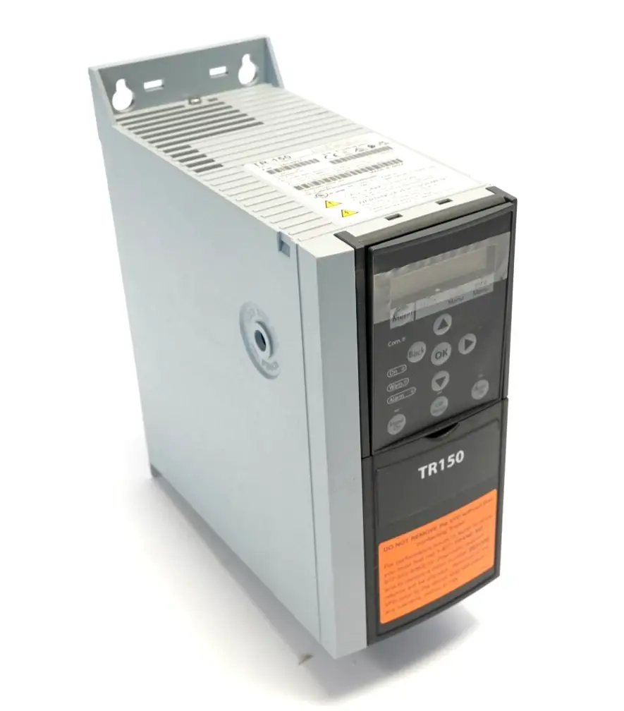
The Trane TR150 VFD is a highly specialized frequency converter designed specifically to meet the demanding requirements of the Heating, Ventilation, and Air Conditioning (HVAC) sector. Its operation in variable torque mode makes it ideal for fan and pump applications, offering precise control and optimal energy efficiency.
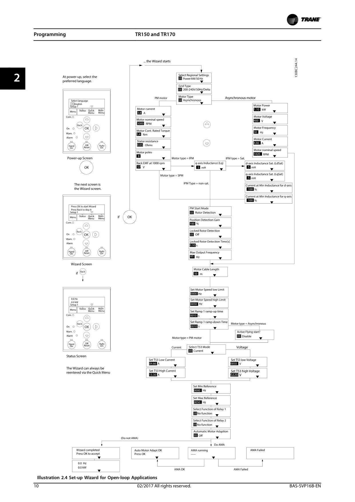
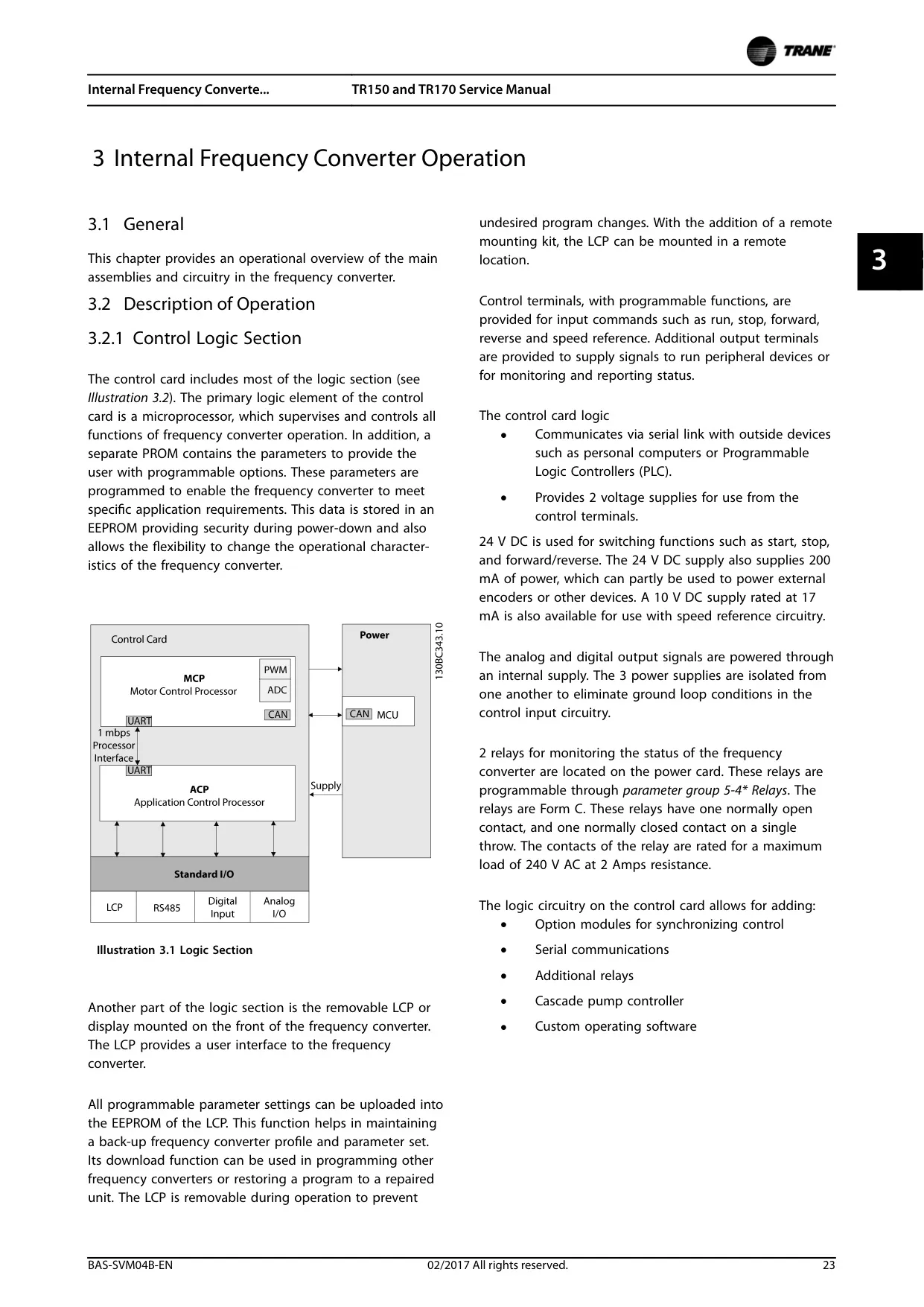
The unit incorporates a robust control logic section centered around a microprocessor that monitors all functions. This allows for flexible programming to adapt the VFD to various application requirements, with parameters stored in an EEPROM for security and ease of modification.
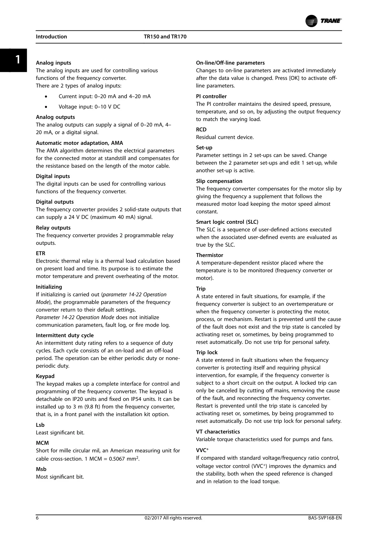
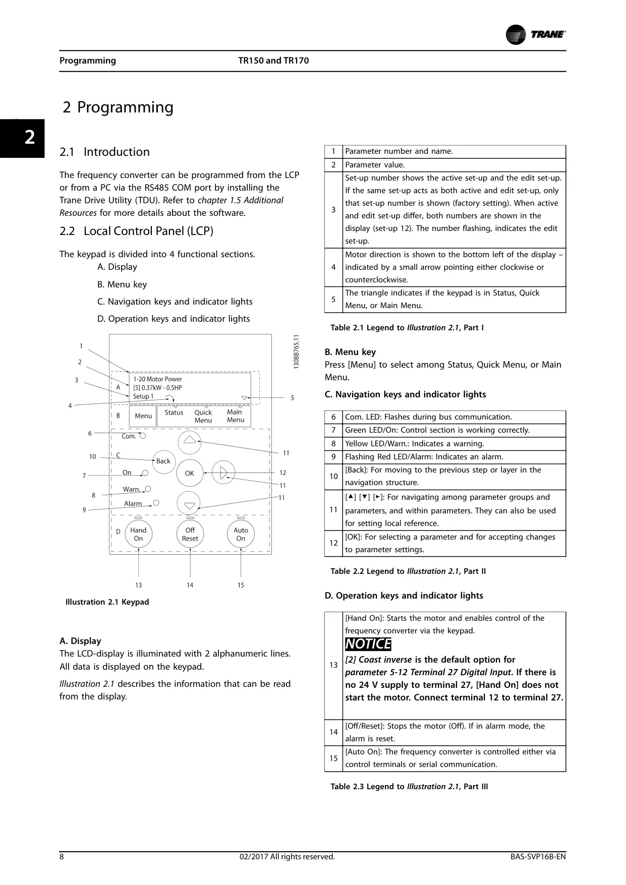
A key feature is the user interface, which can be either a numerical or graphical Local Control Panel (LCP). In addition to providing a clear display of status and settings, this panel allows the uploading and downloading of parameter profiles, facilitating the configuration of multiple units or restoration after maintenance.
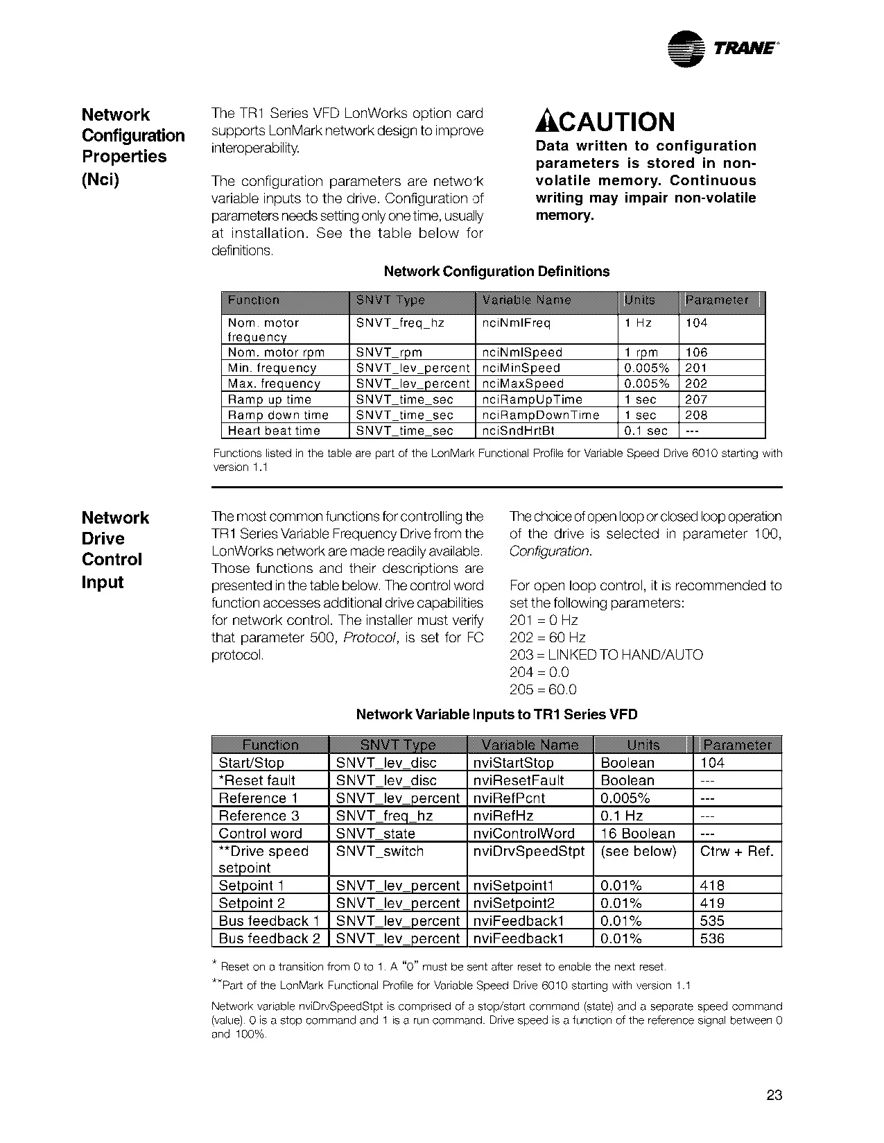
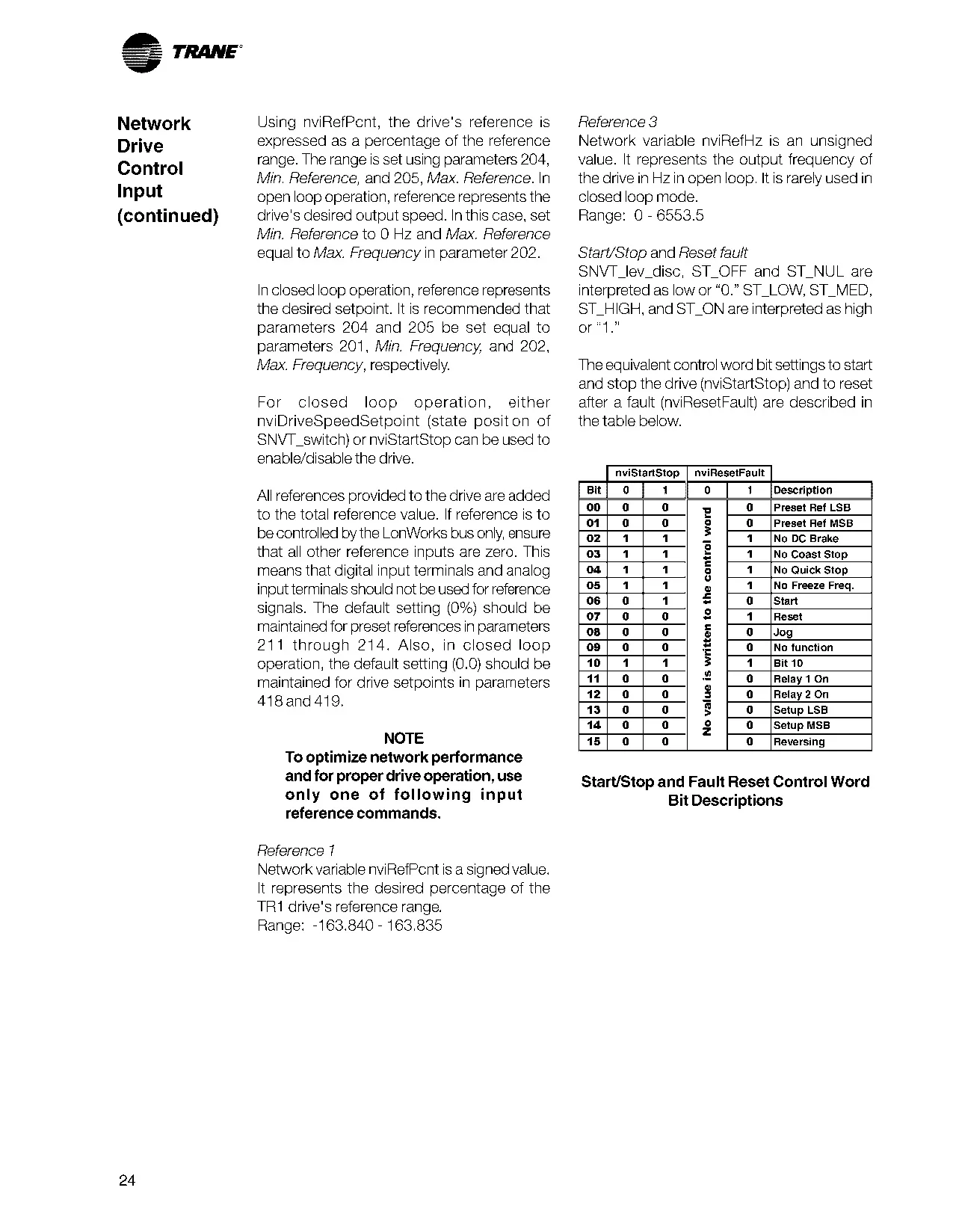
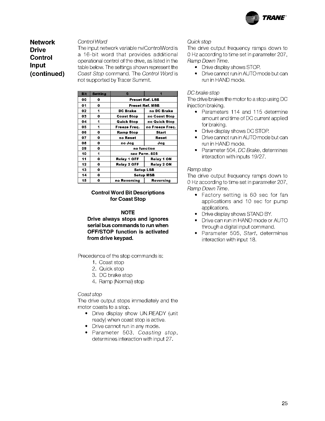
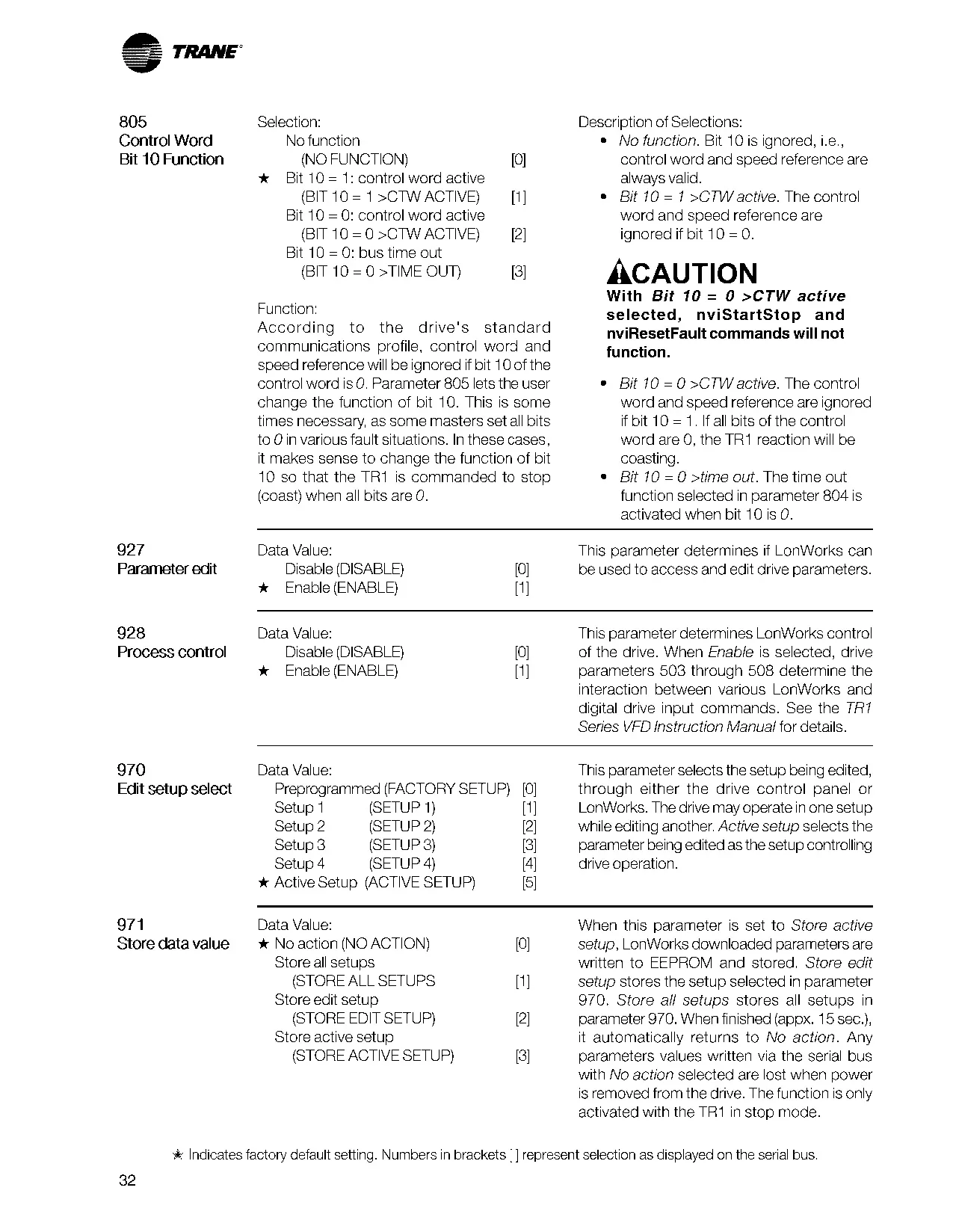
The TR150 VFD accepts various control signals. It can receive commands via the LCP, serial communication (using the RS485 port or a communication option card), or through signal wiring to its control terminals. This includes digital inputs for commands such as start, stop, and reverse, as well as analog inputs for speed references or sensor feedback.
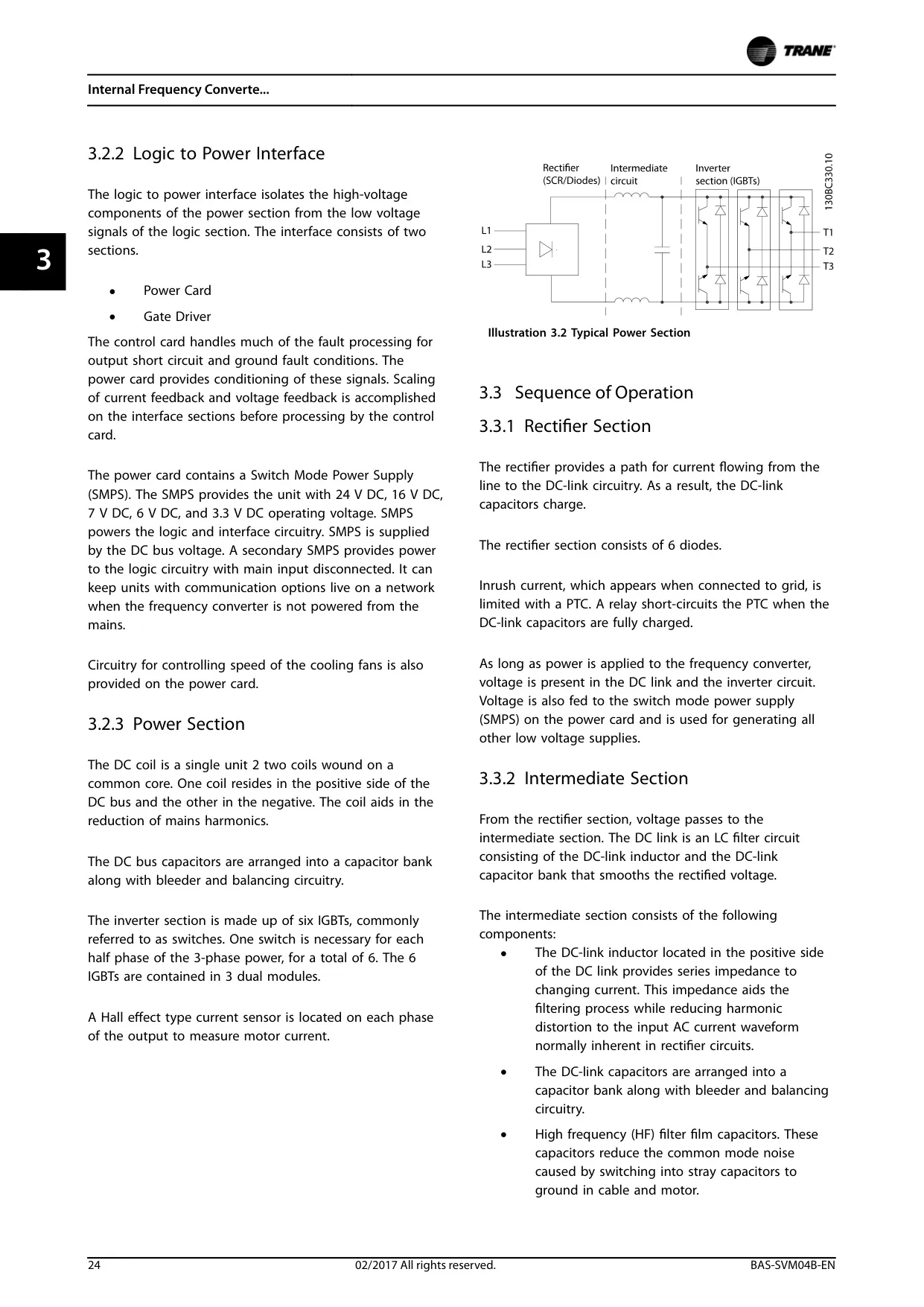
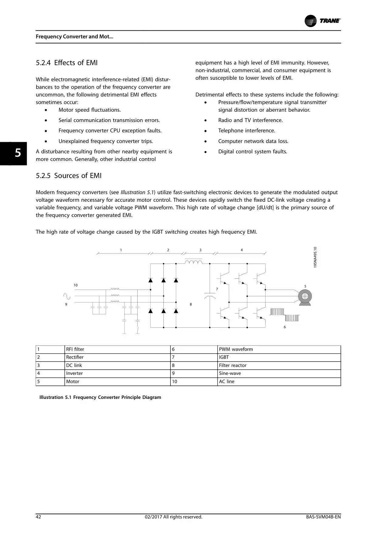
The power section of the VFD is engineered for efficient and safe energy conversion. It includes a rectifier section with 6 diodes and a DC link inductor to smooth the voltage. The inverter stage utilizes six IGBTs to generate the Pulse Width Modulated (PWM) output waveform, ensuring optimal motor performance with minimal losses.
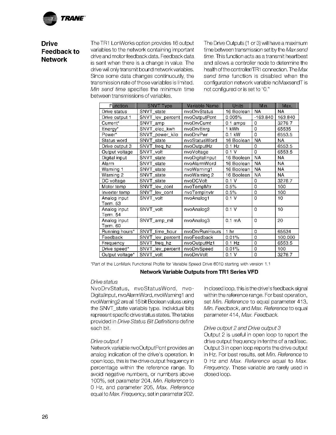
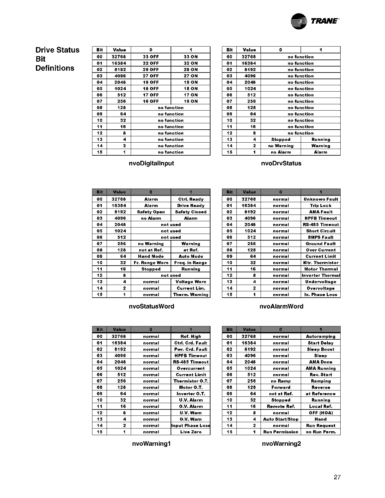
In addition to its control capabilities, the TR150 VFD offers a series of service and diagnostic features. Status messages on the LCP inform about the operating mode, active references, and overall status. The system also logs fault events and issues warnings or alarms for conditions arising both internally and externally, facilitating quick troubleshooting.
The adaptability of the TR150 VFD extends to its input and output configuration. The control terminals are programmable, allowing the technician to define how the VFD responds to input signals and the type of signal present at its outputs, such as frequency, current, or torque. This flexibility is crucial for integration into complex automation systems.
Internally, the VFD features a power card that includes a Switch Mode Power Supply (SMPS) to supply operating voltages to the logic circuits. This design ensures isolation between high- and low-voltage components, as well as the ability to keep communication options active even when the unit is not powered from the main grid.
To ensure long-term reliability, the system incorporates fan speed control based on heatsink temperature. This ensures efficient cooling and extends component life. Short-circuit and overcurrent protection is achieved through current measurement in the motor phases or DC link, disabling IGBTs individually if allowed limits are exceeded.
Frequently Asked Questions (FAQs)
Can't find the answer you need? Here are some frequently asked questions about the Trane TR150 VFD, and we answer them below.