Trane TR170 Variable Frequency Drive Instruction Manual
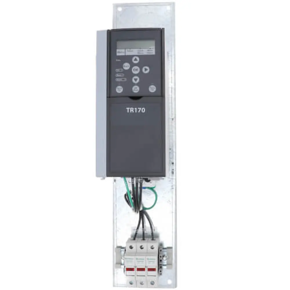
Trane TR170 Variable Frequency Drive
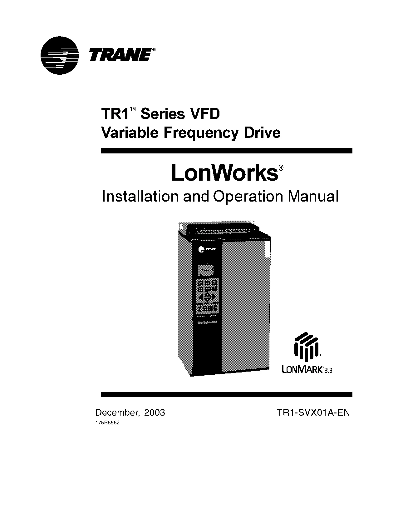
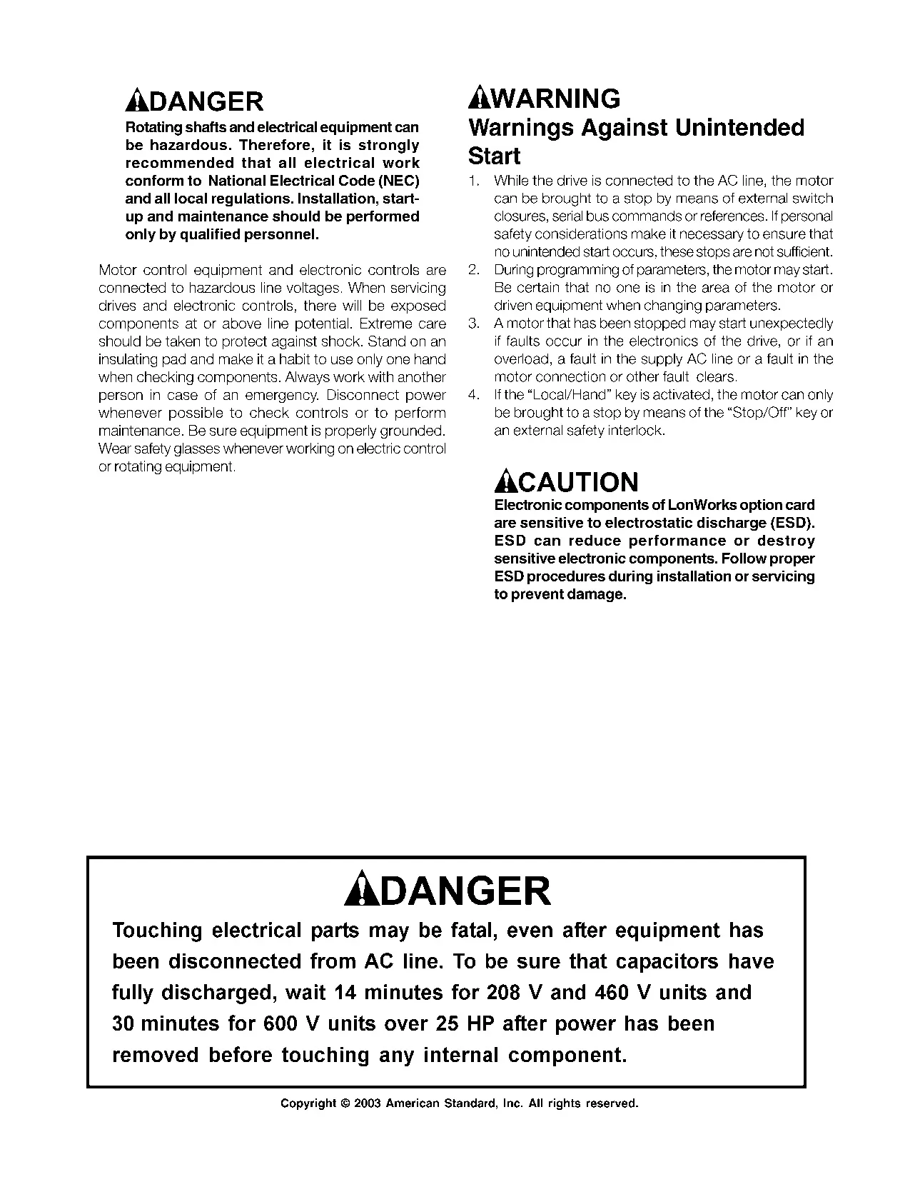



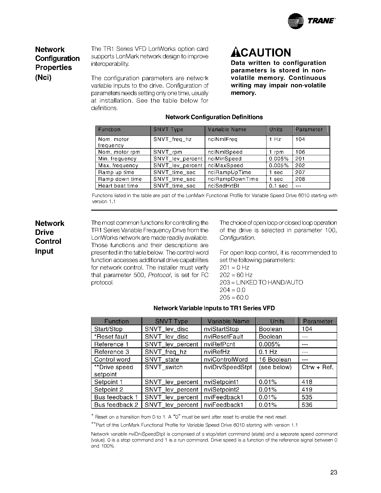
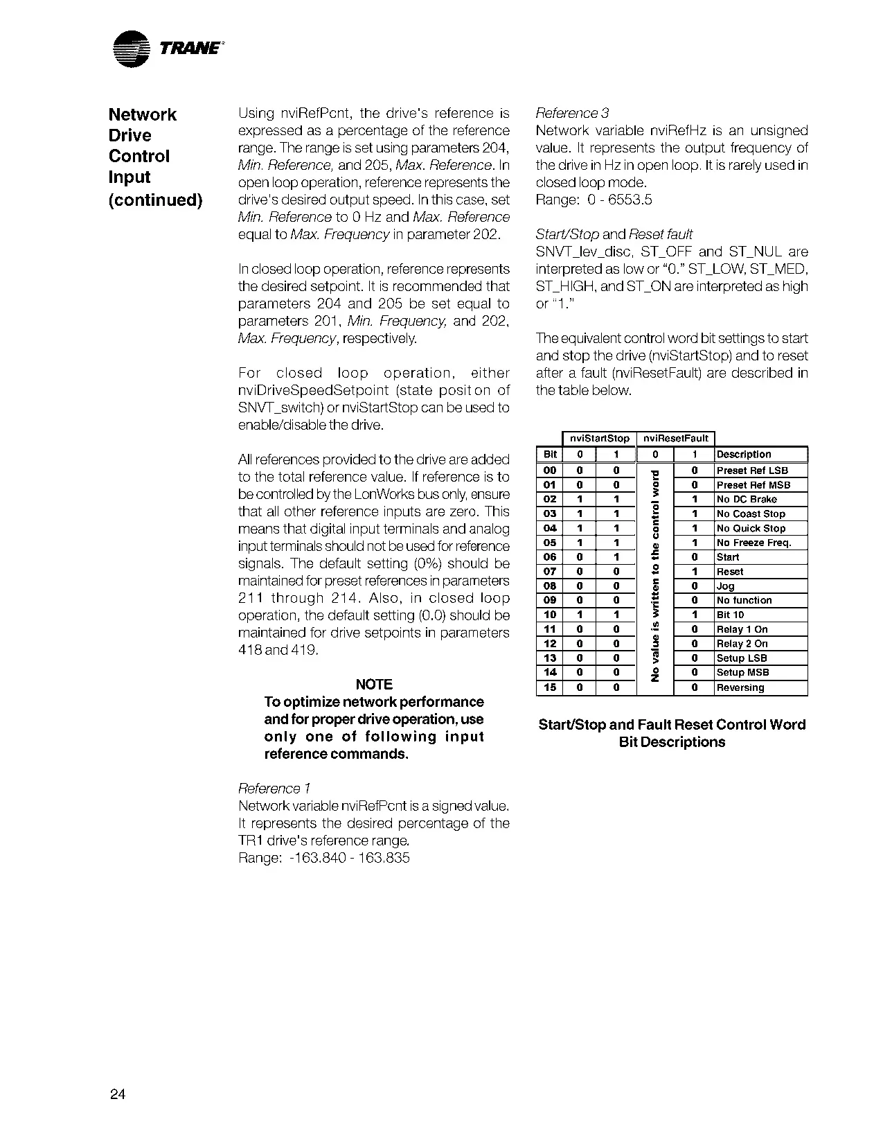
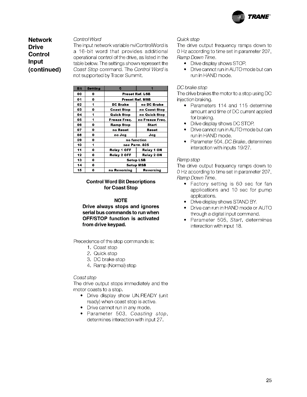
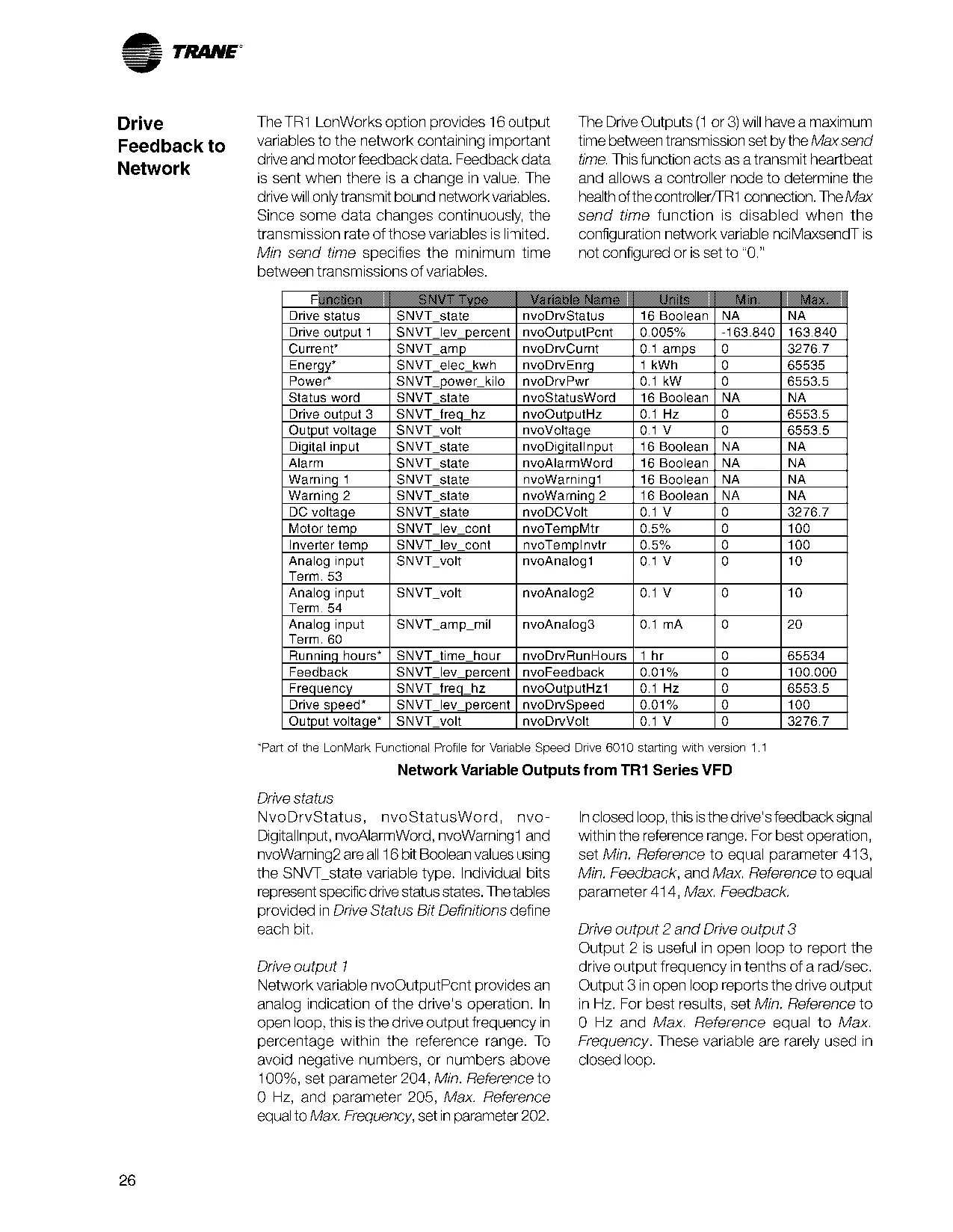
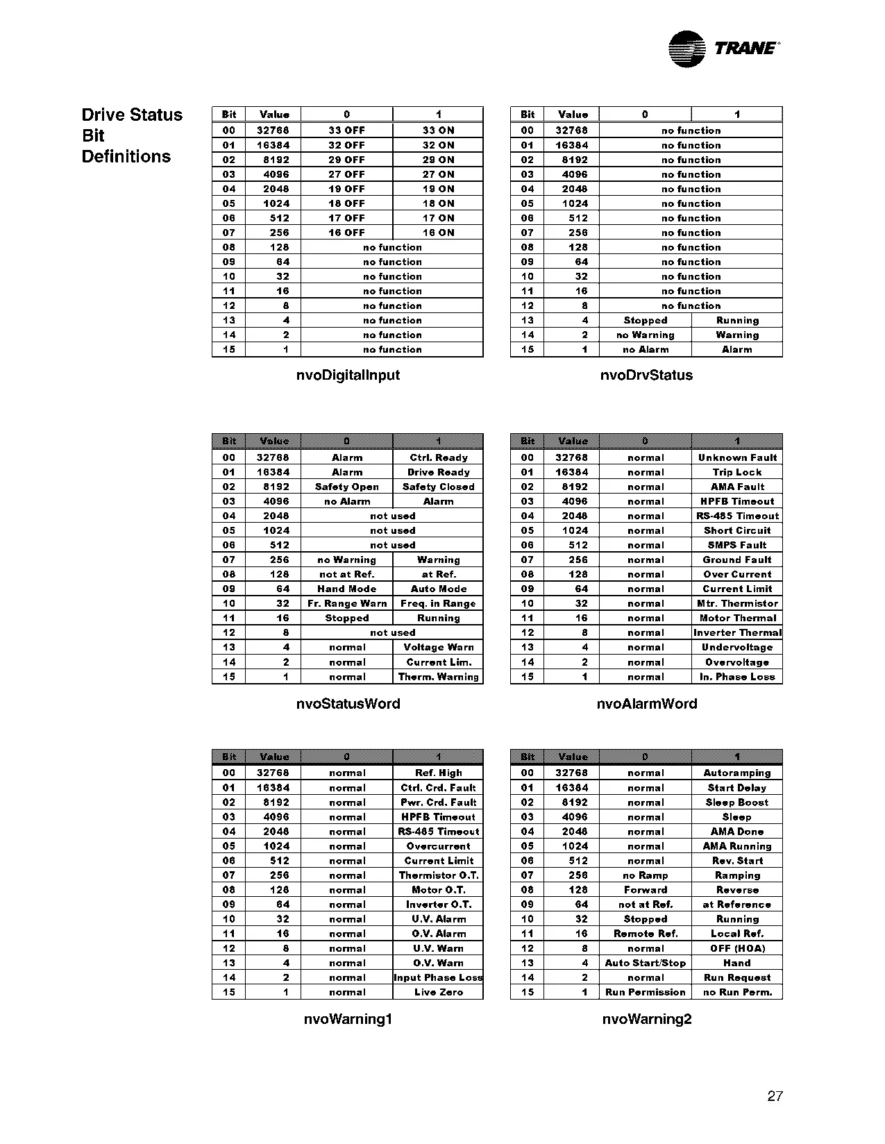
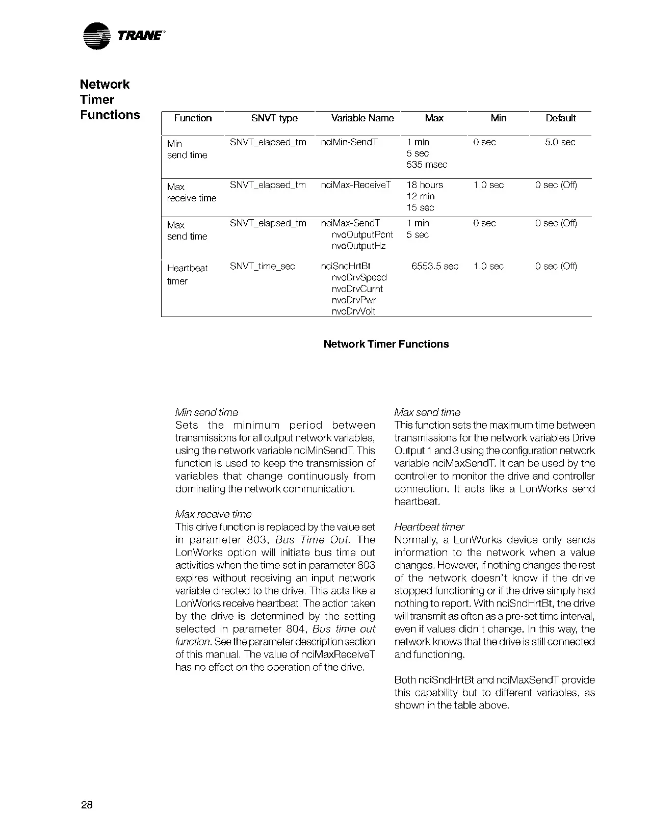
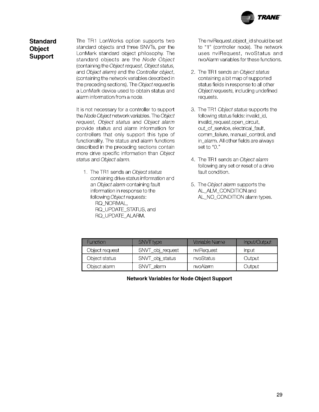

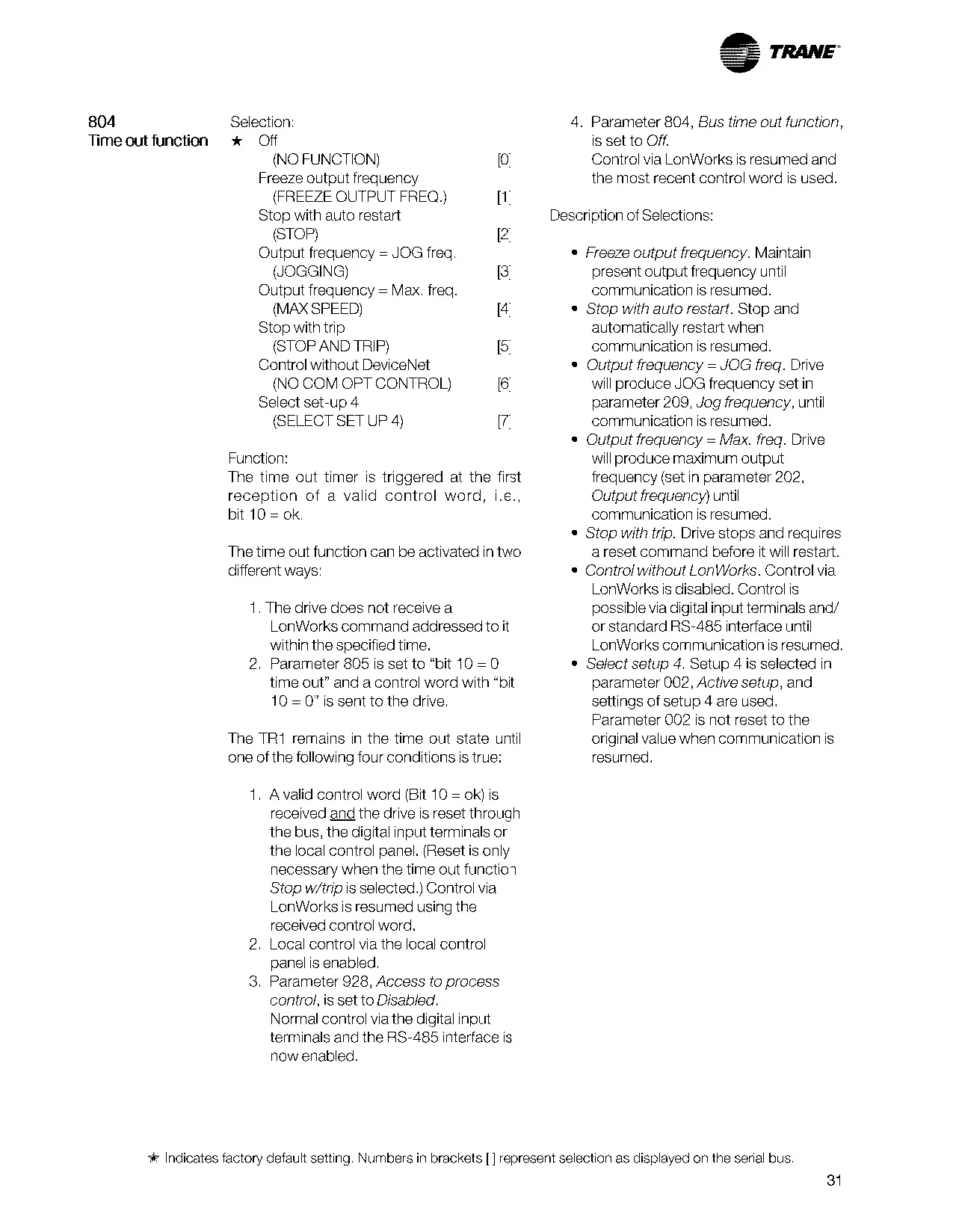
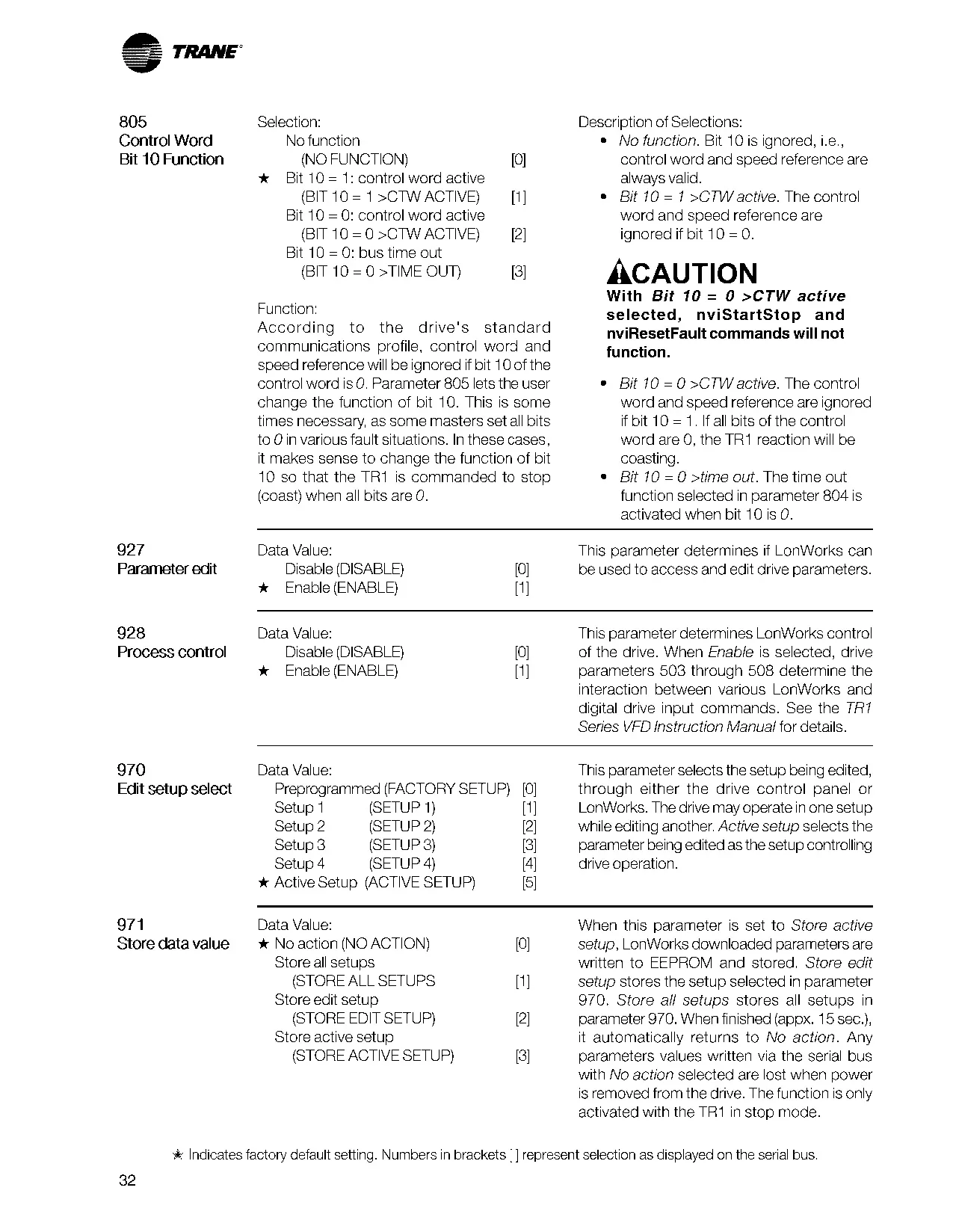
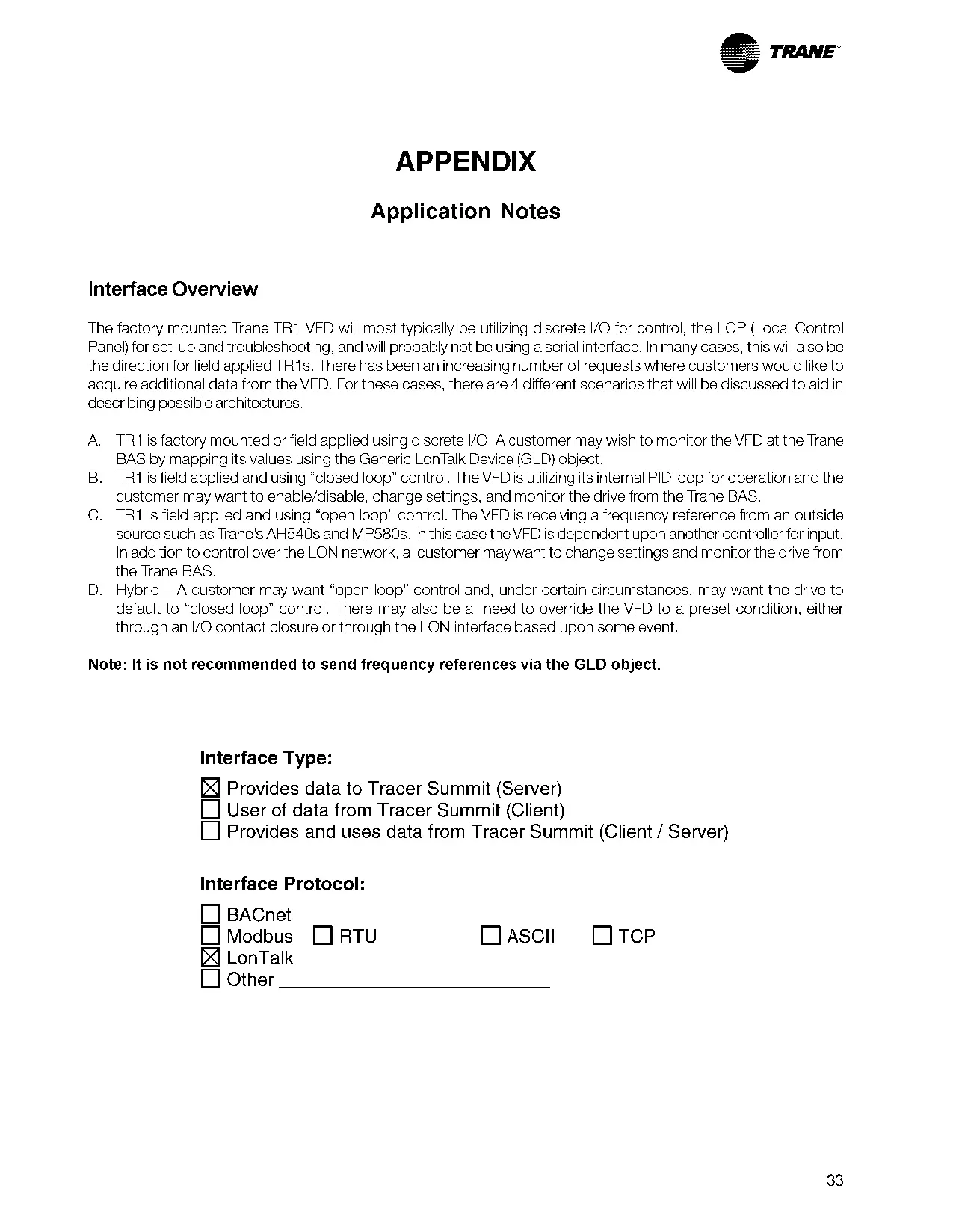
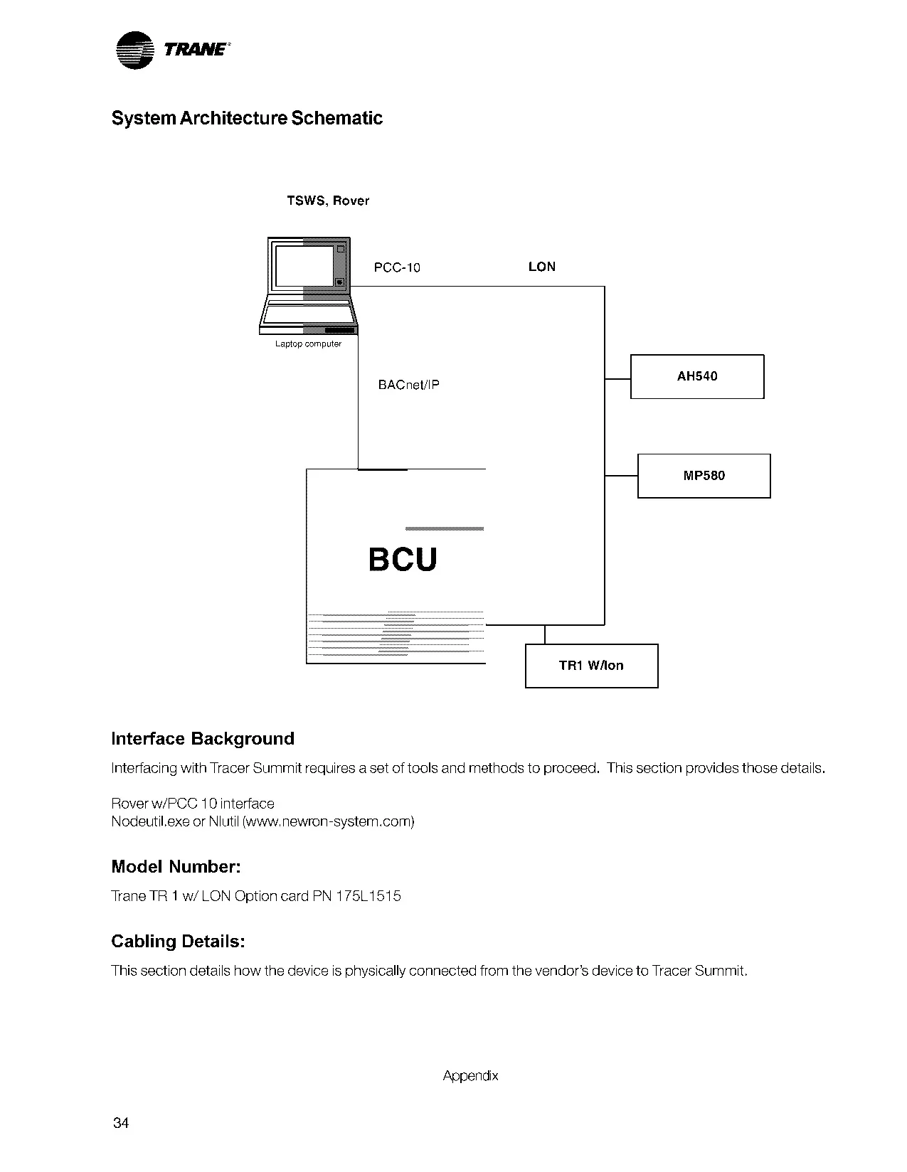
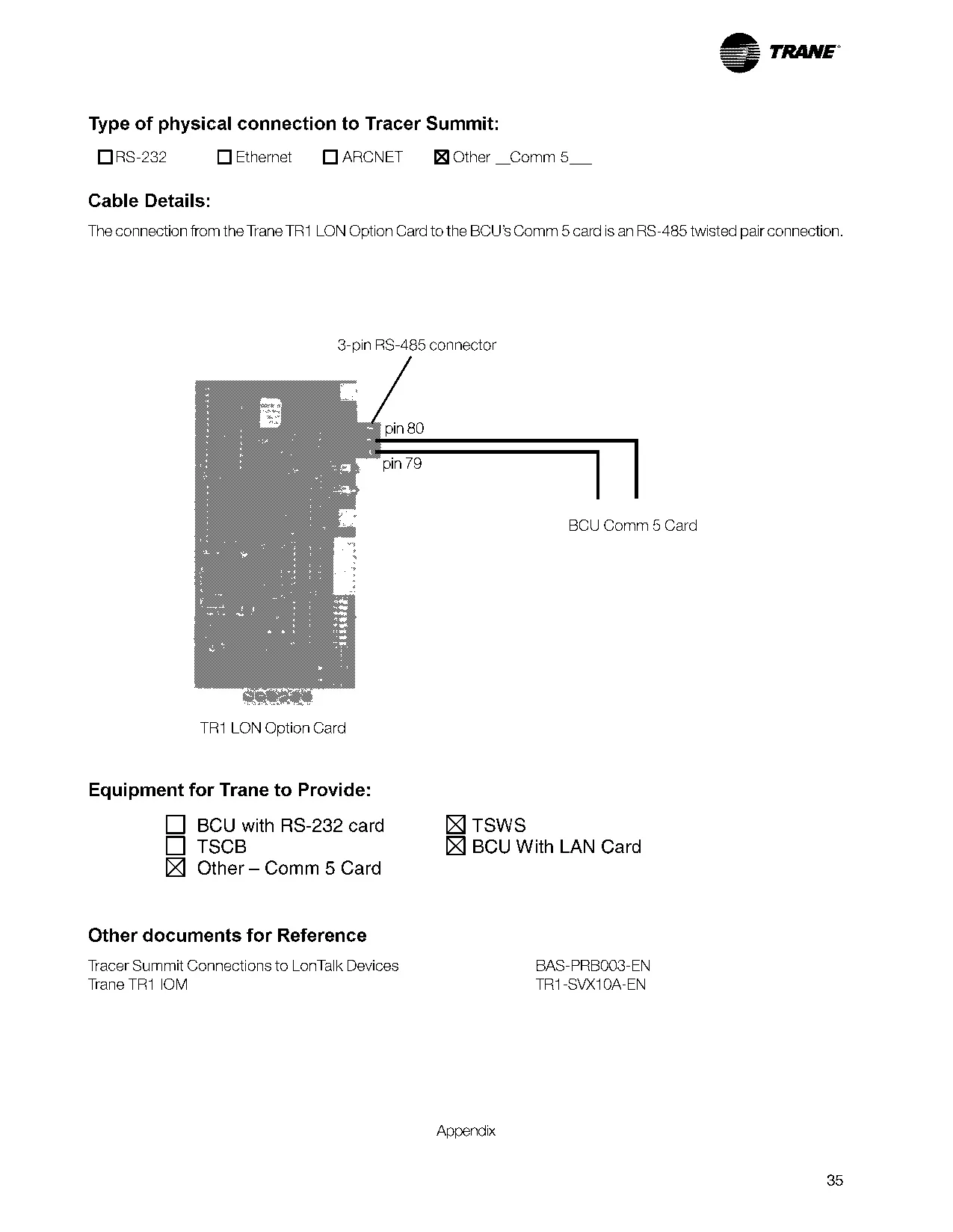
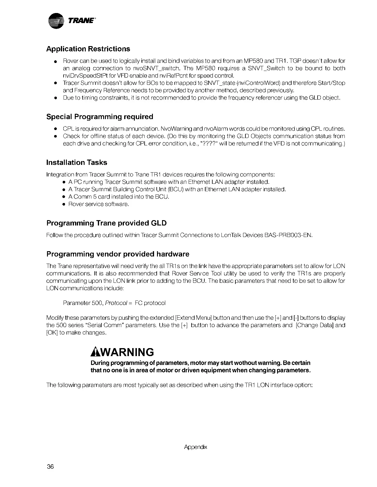
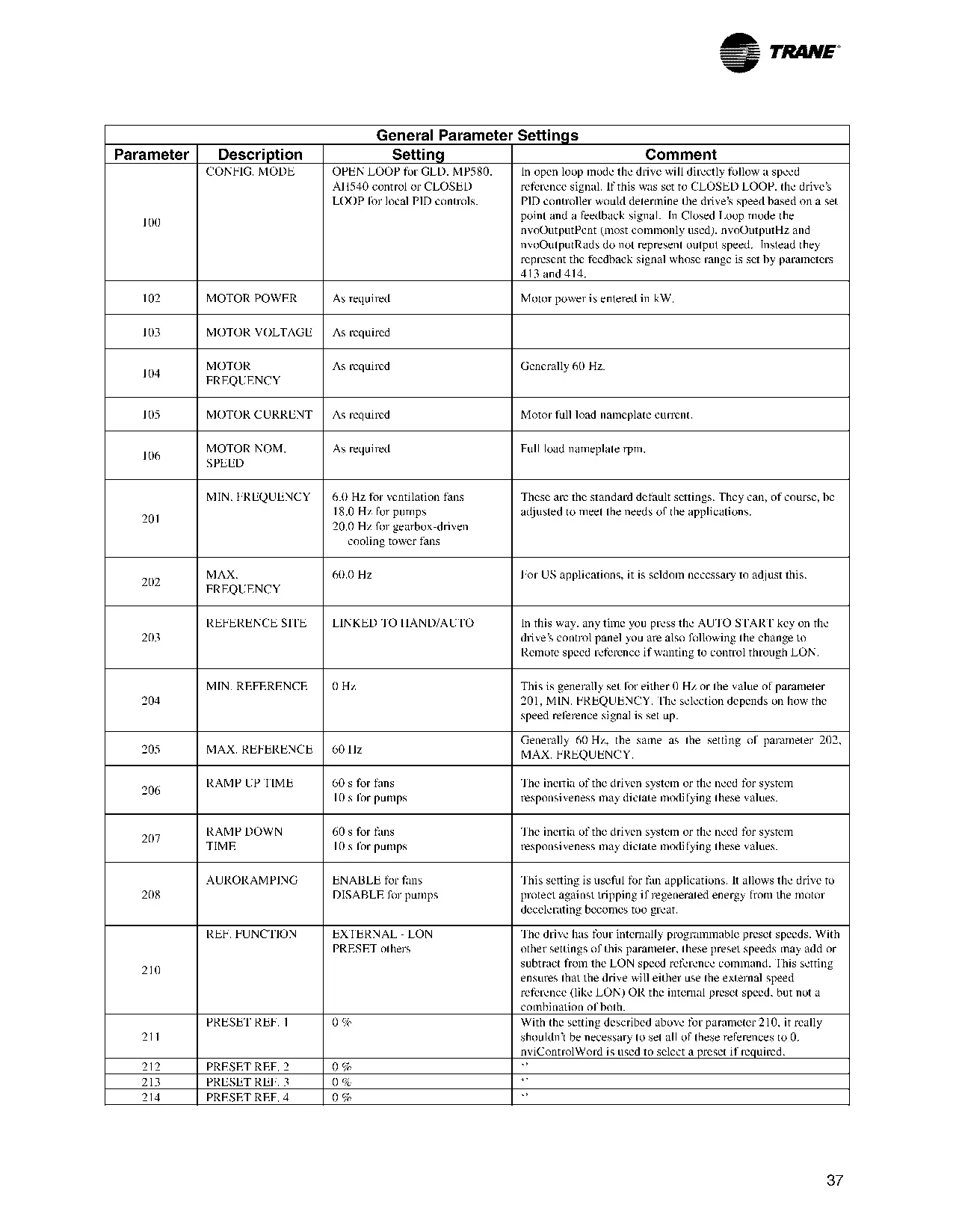

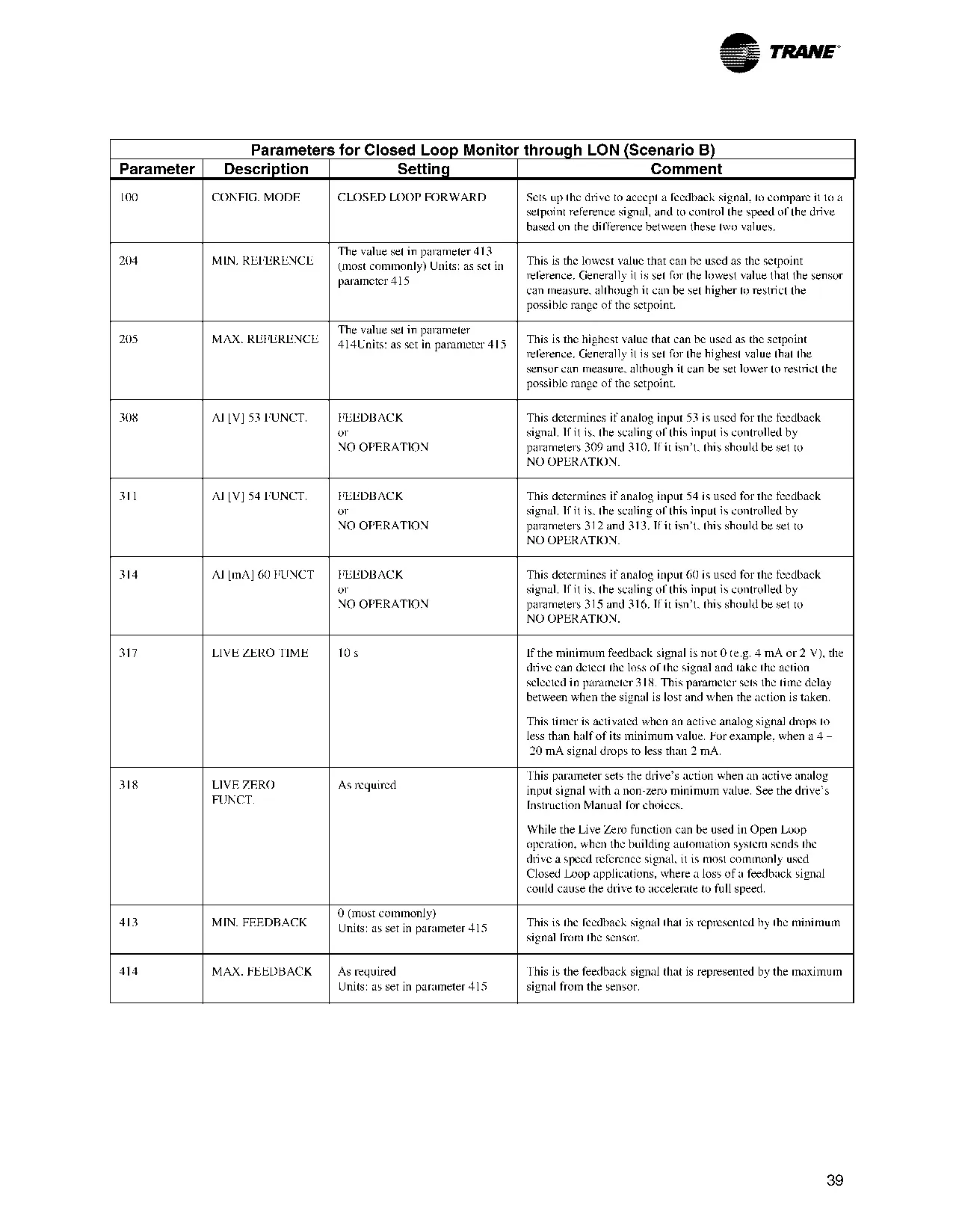
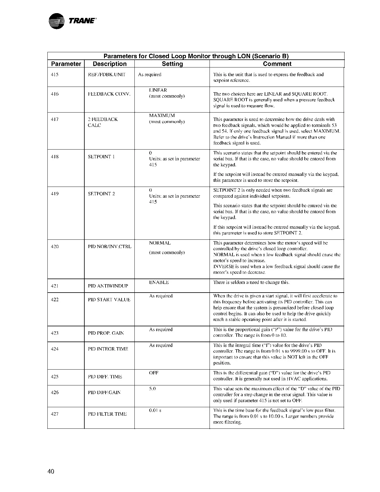
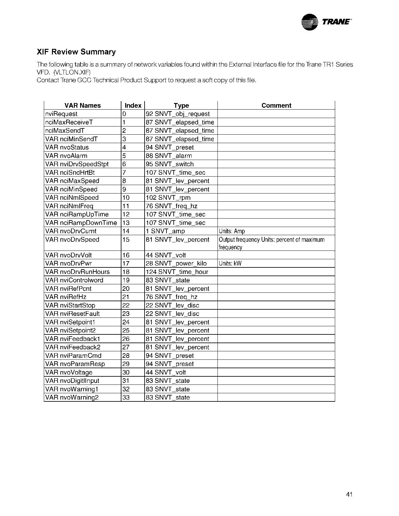
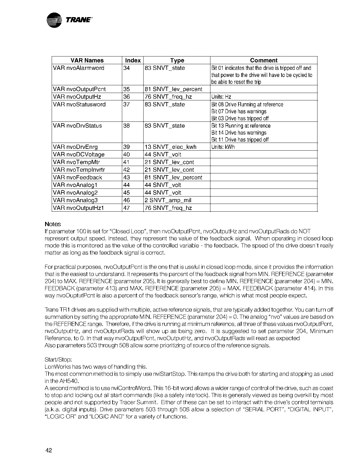
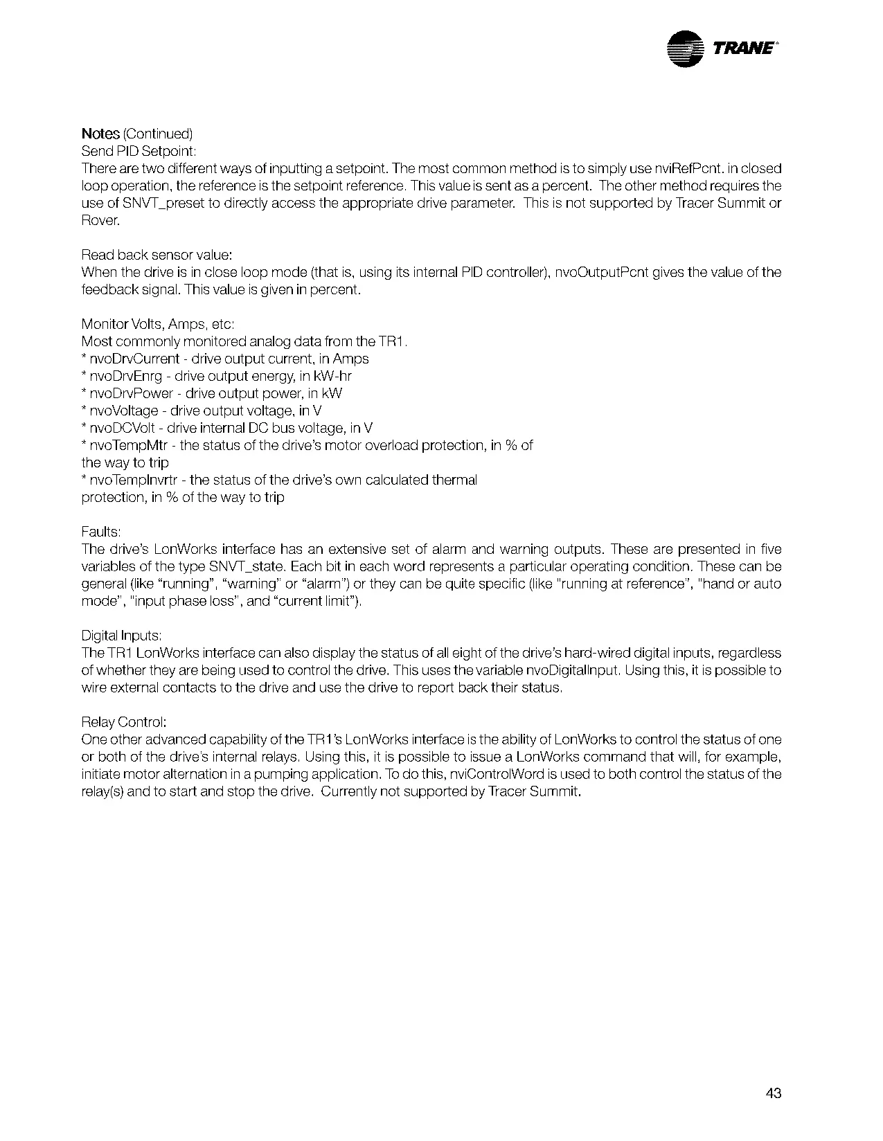


Trane TR170 Variable Frequency Drive
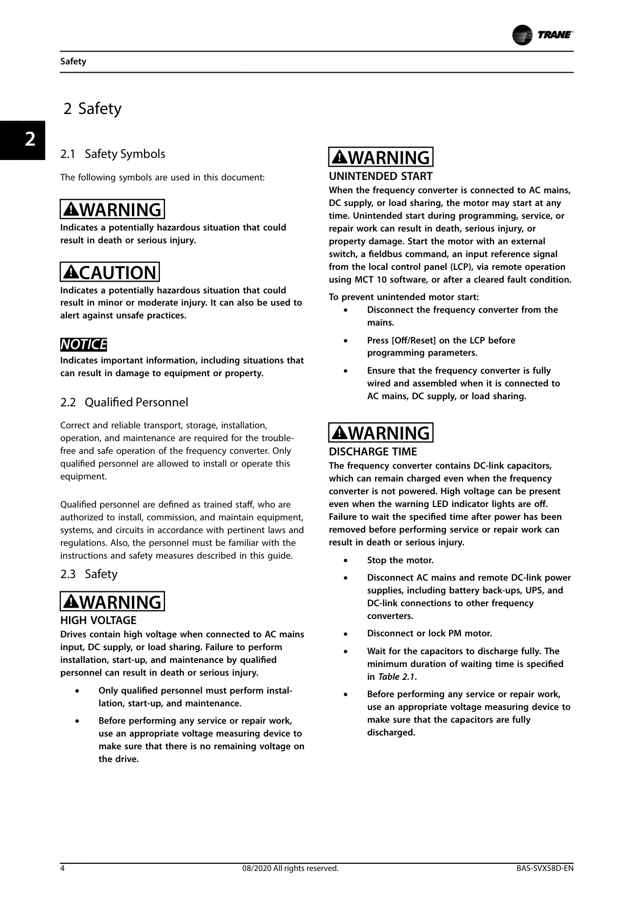
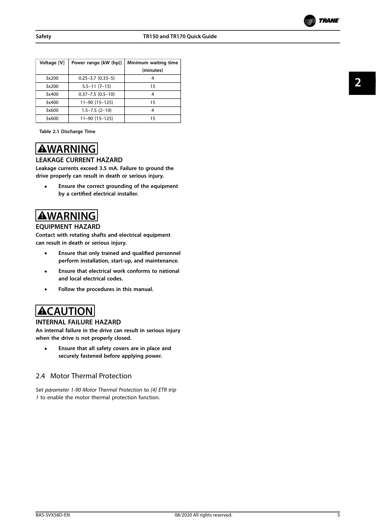
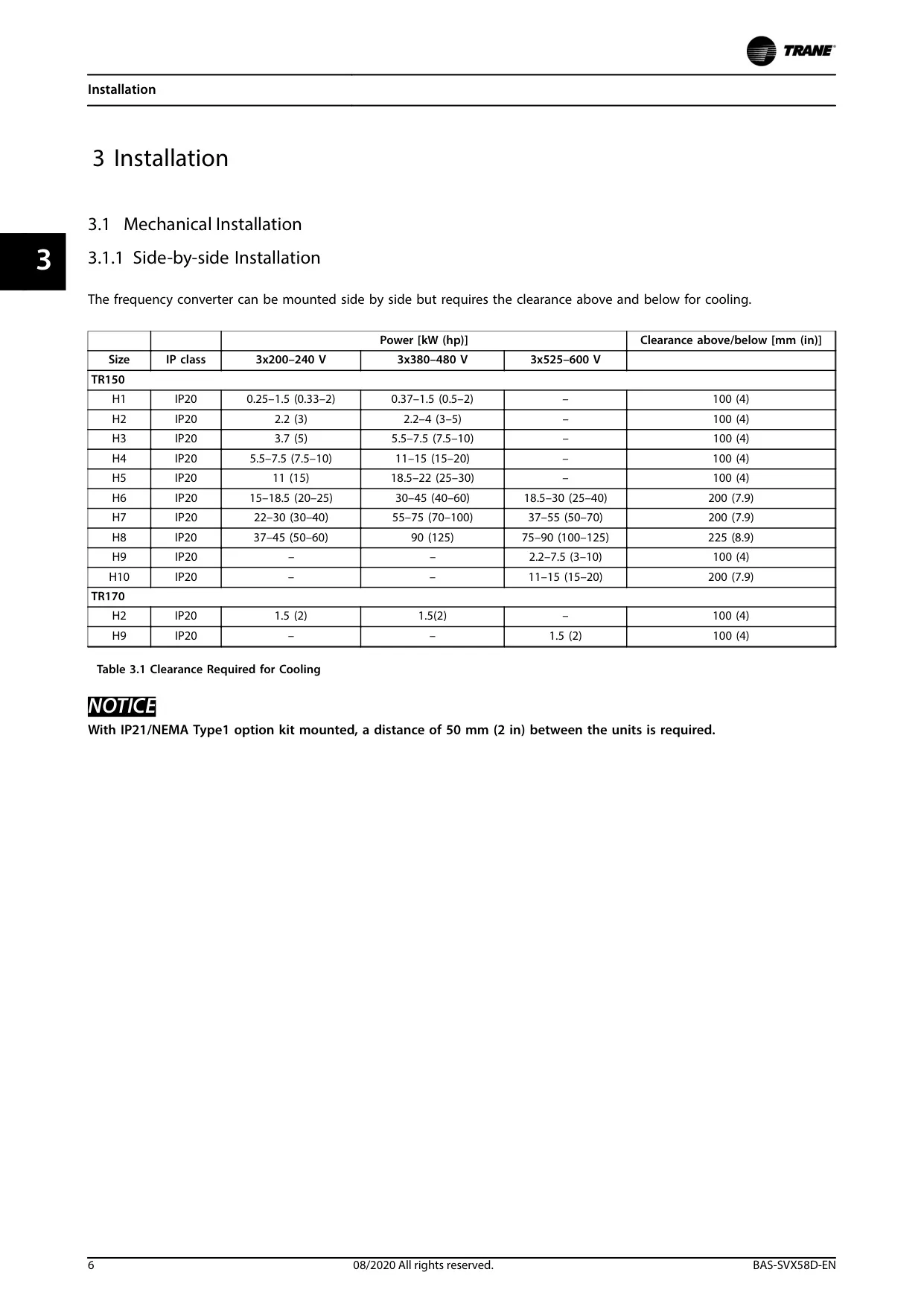
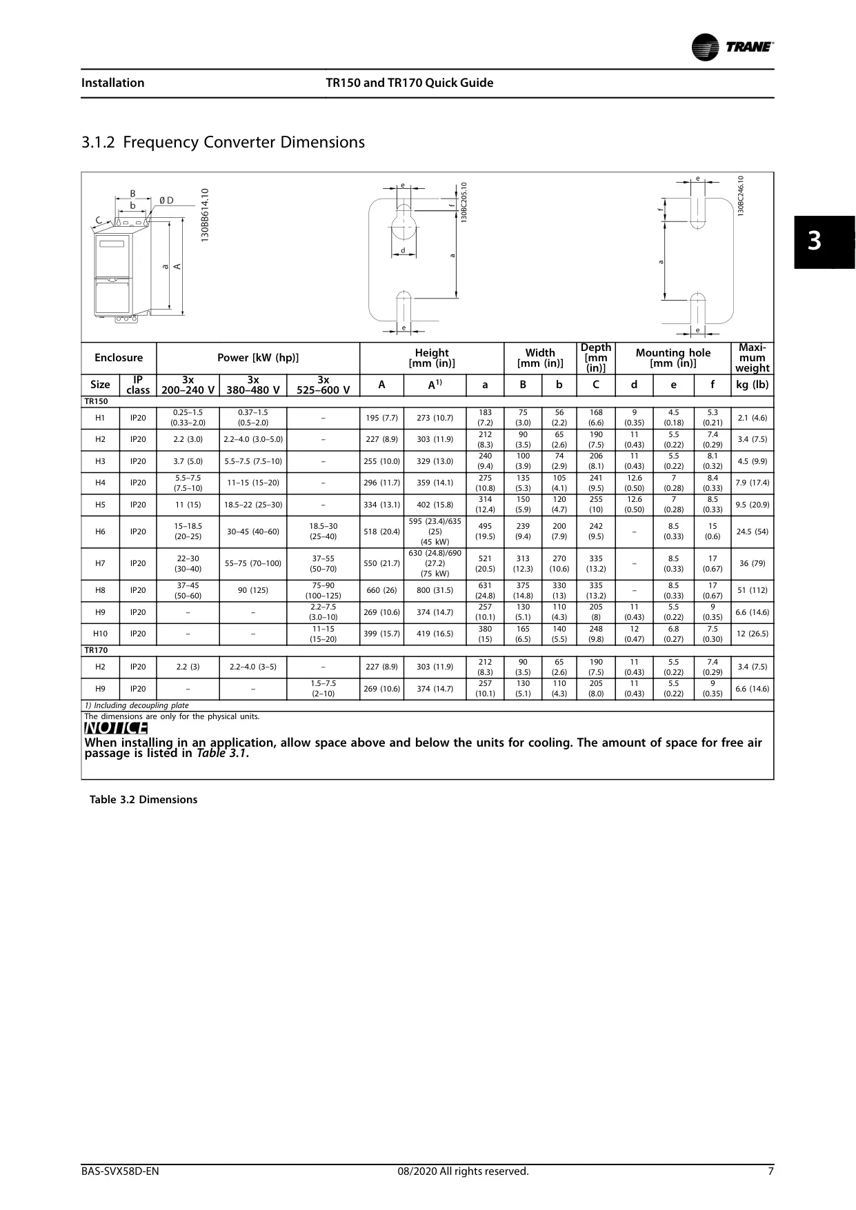










Trane TR170 Variable Frequency Drive

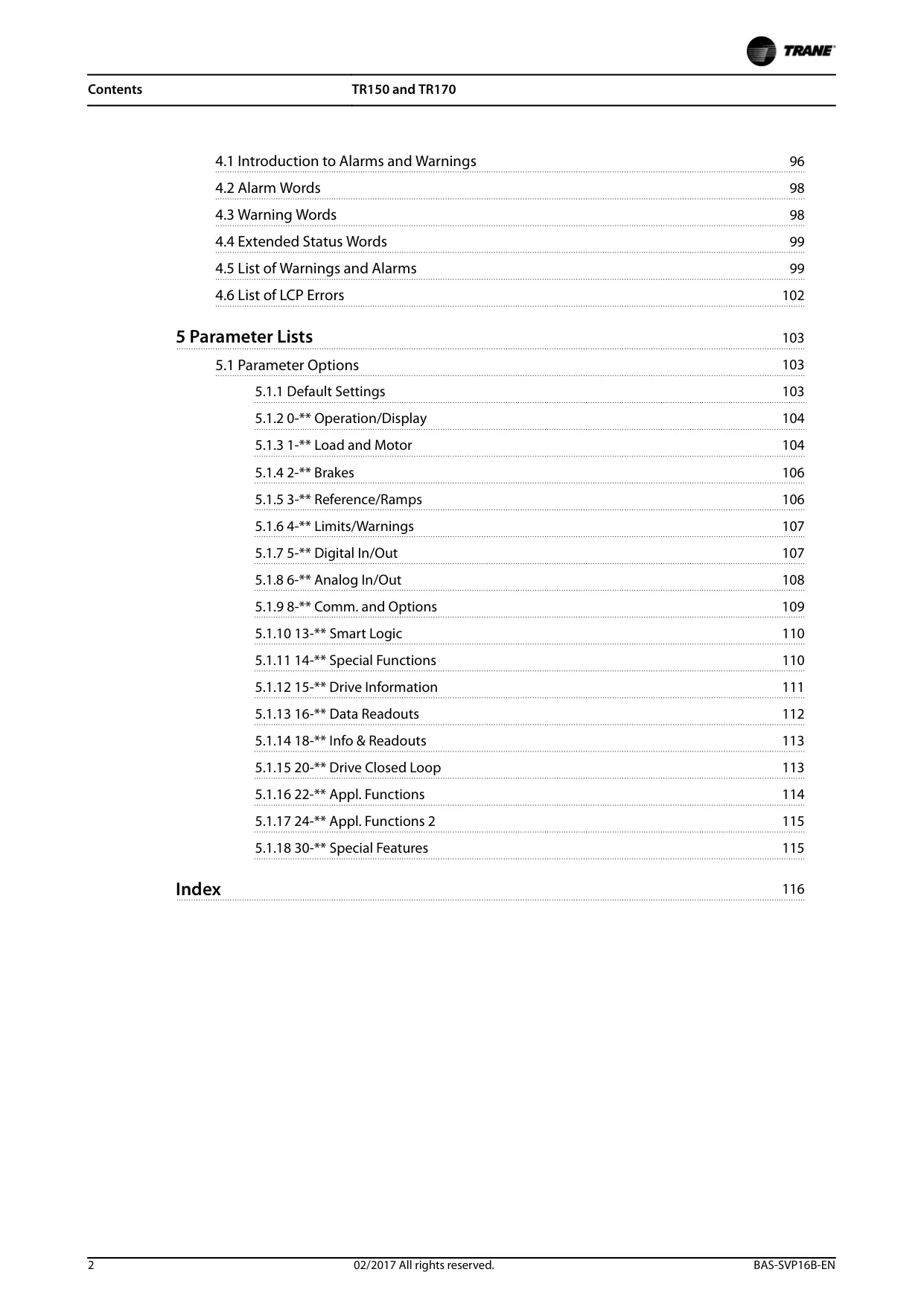
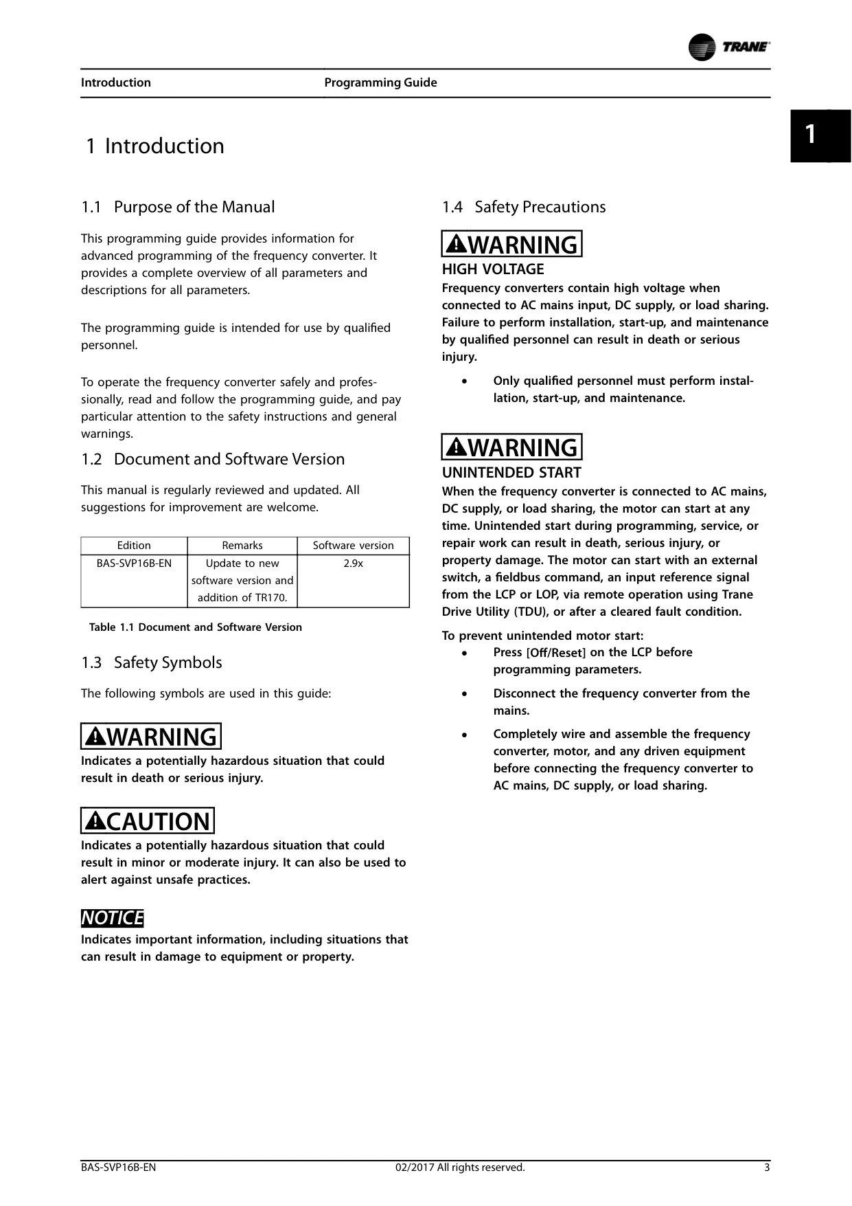
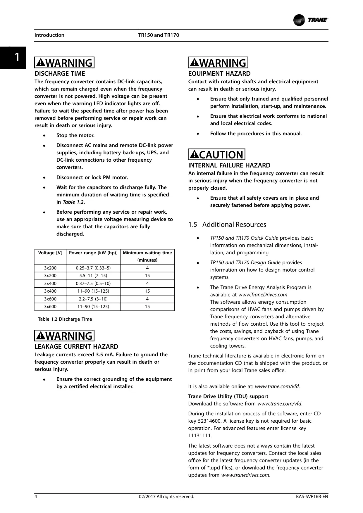
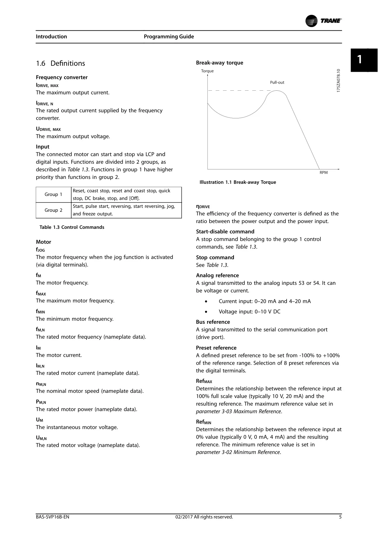

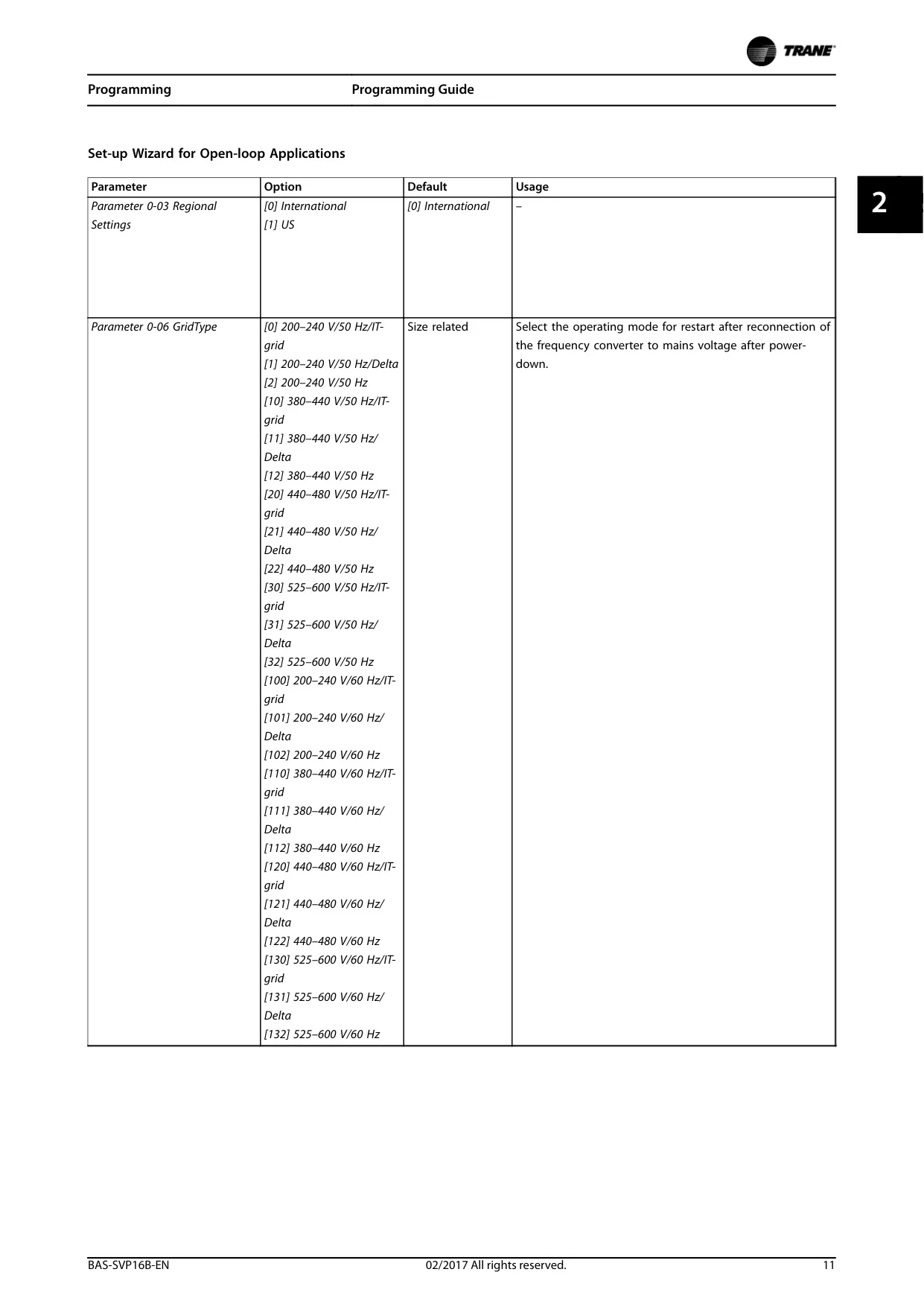
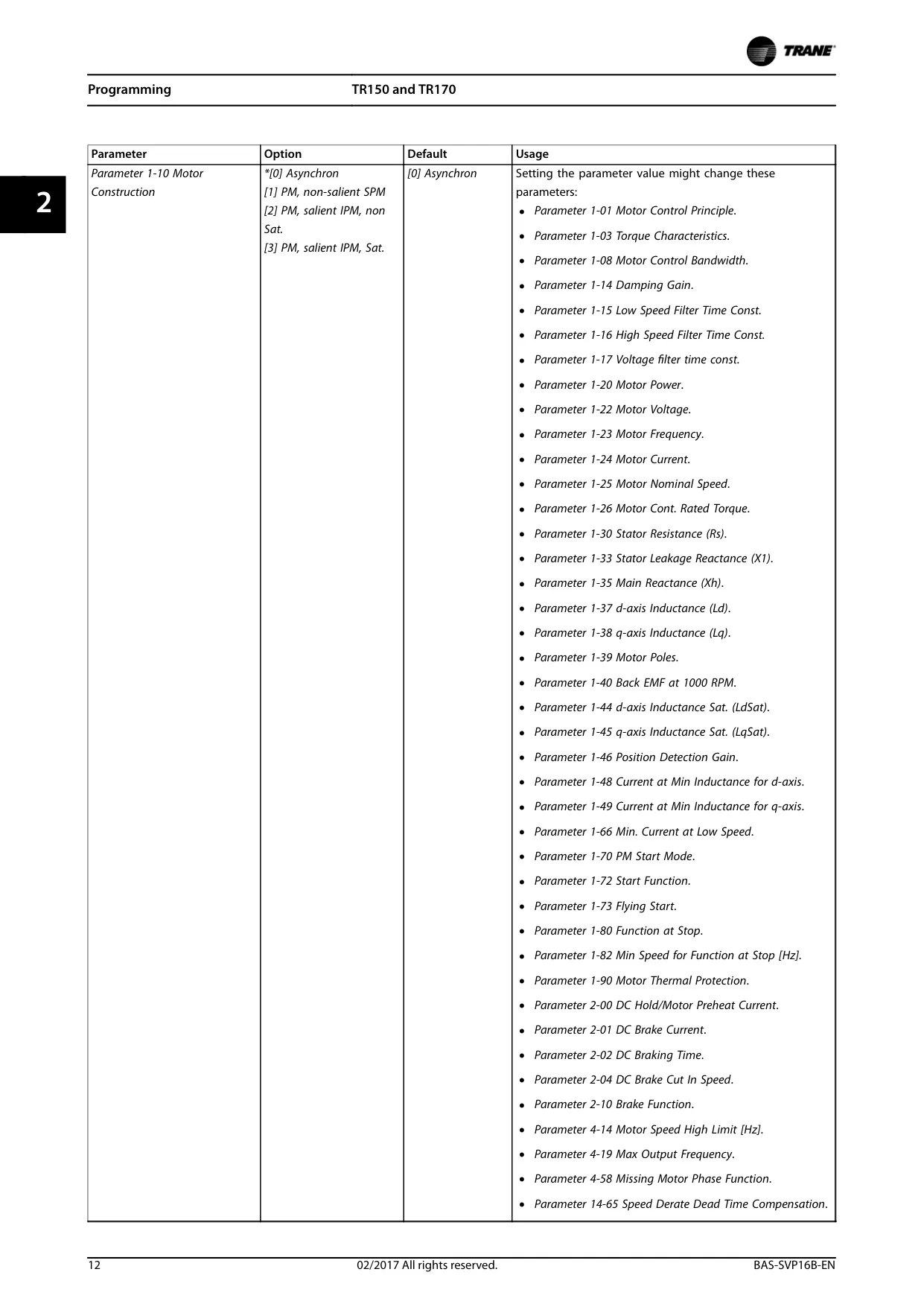
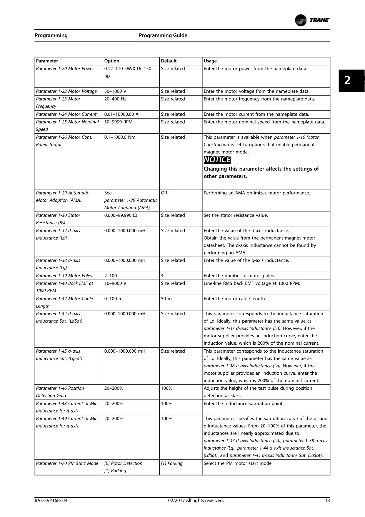
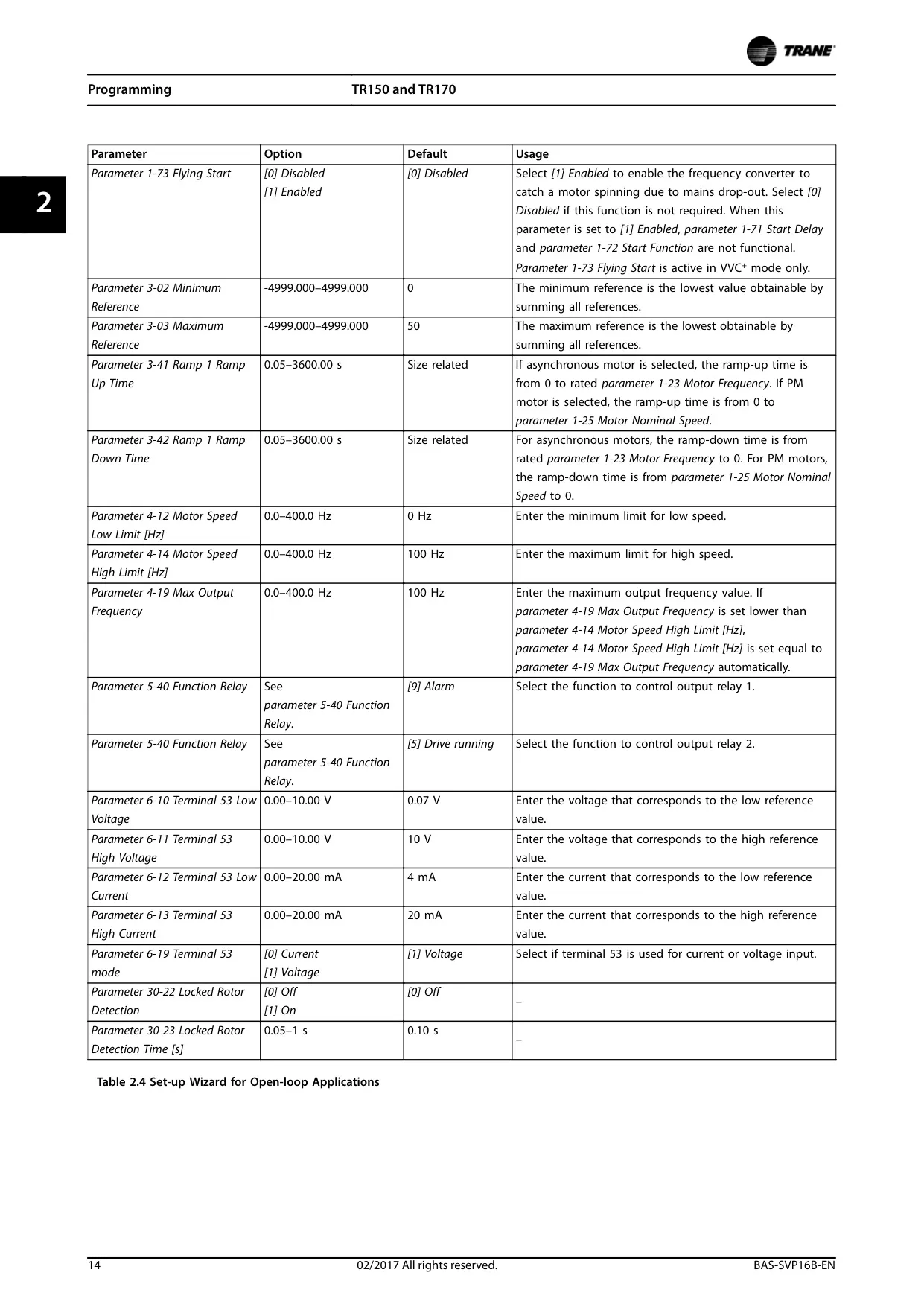

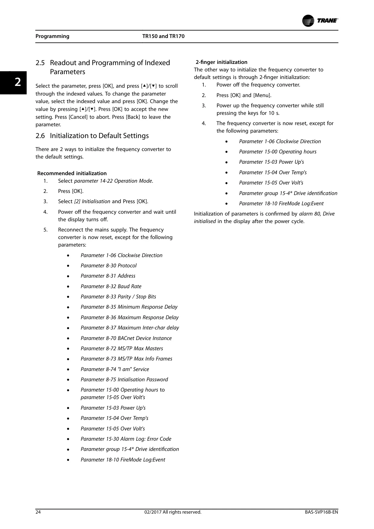
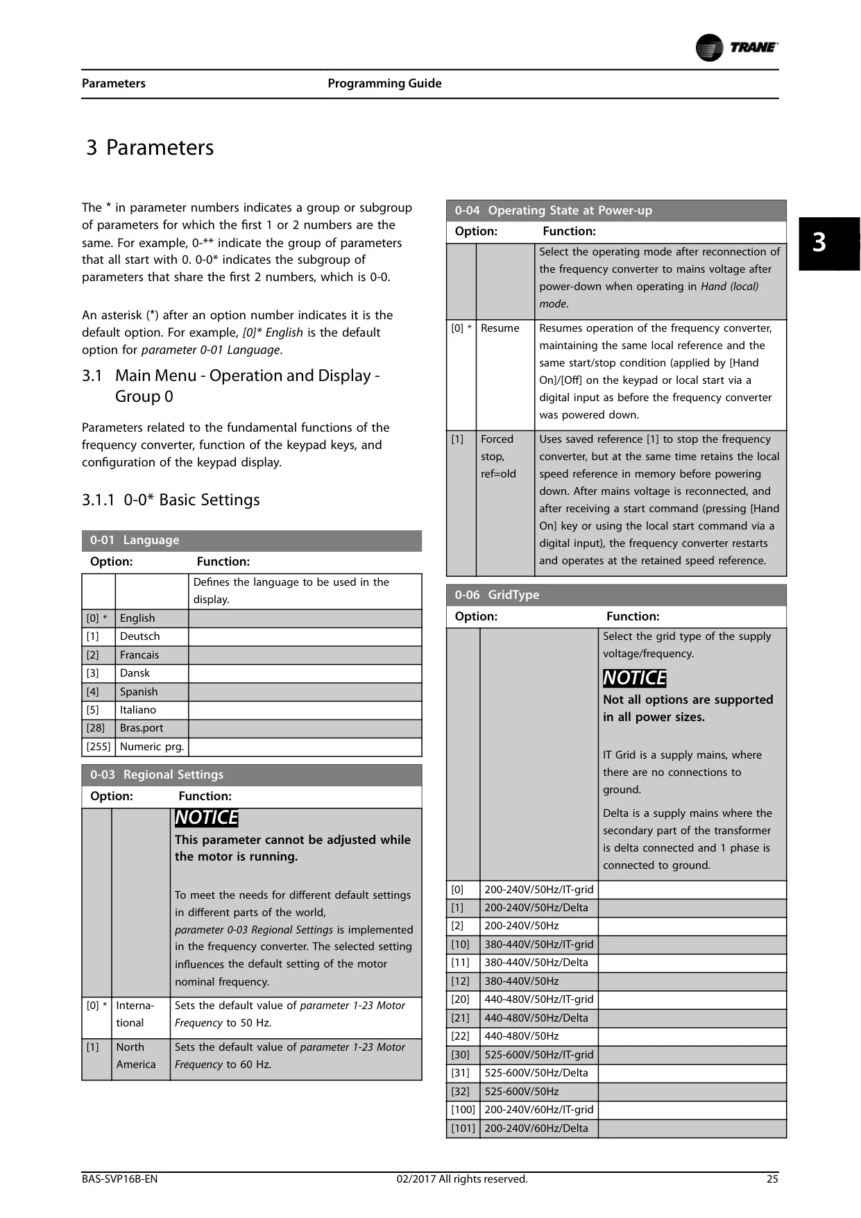
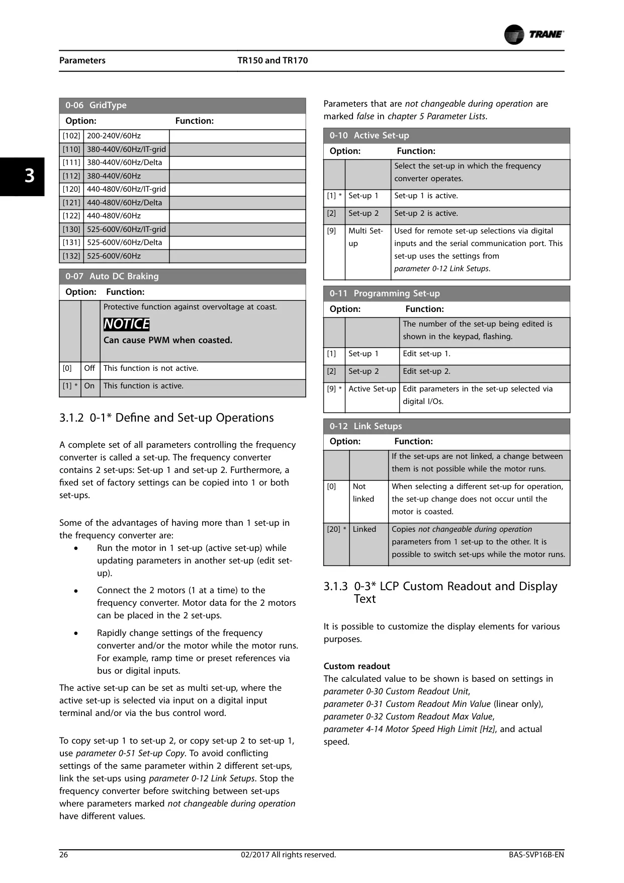


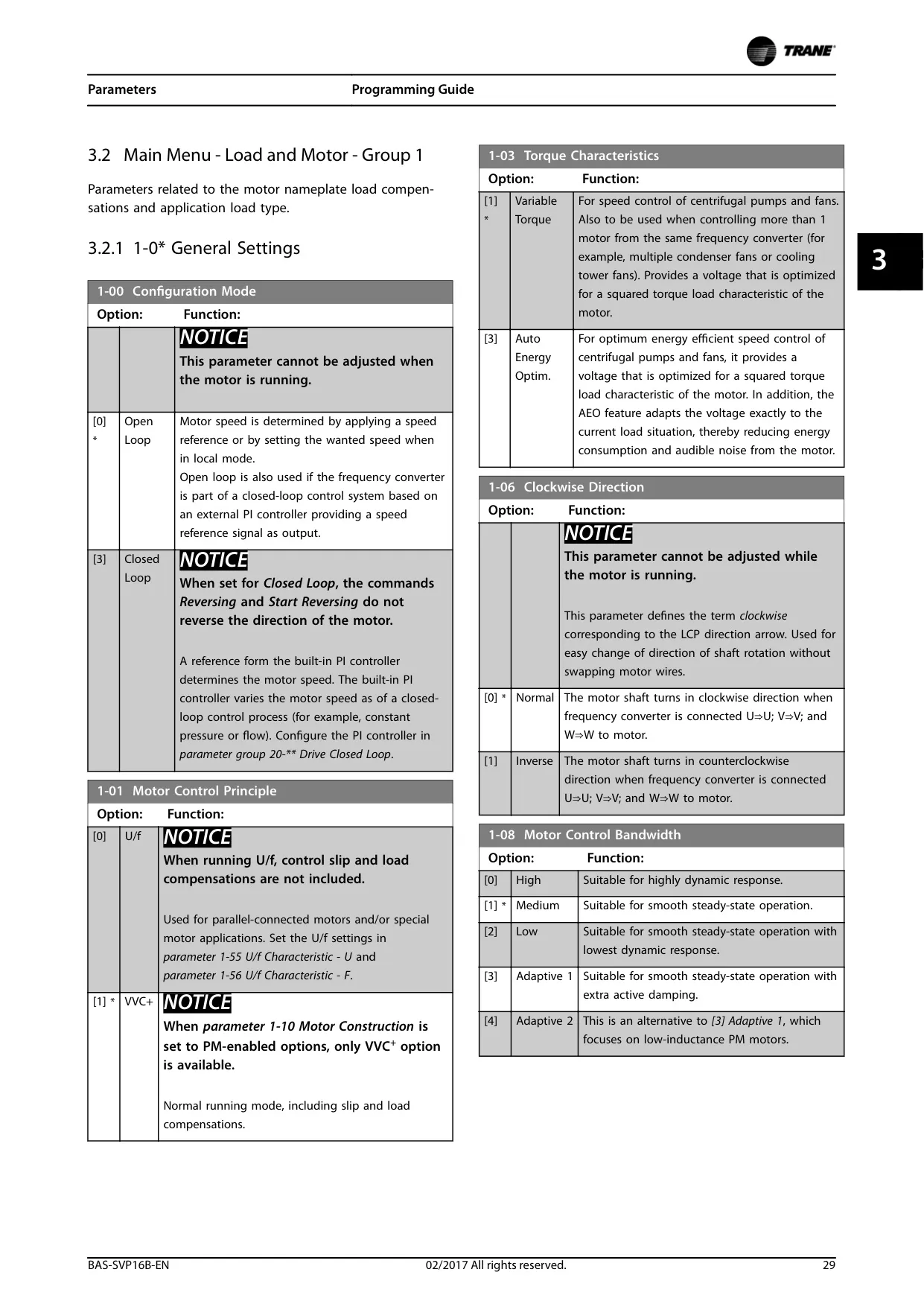
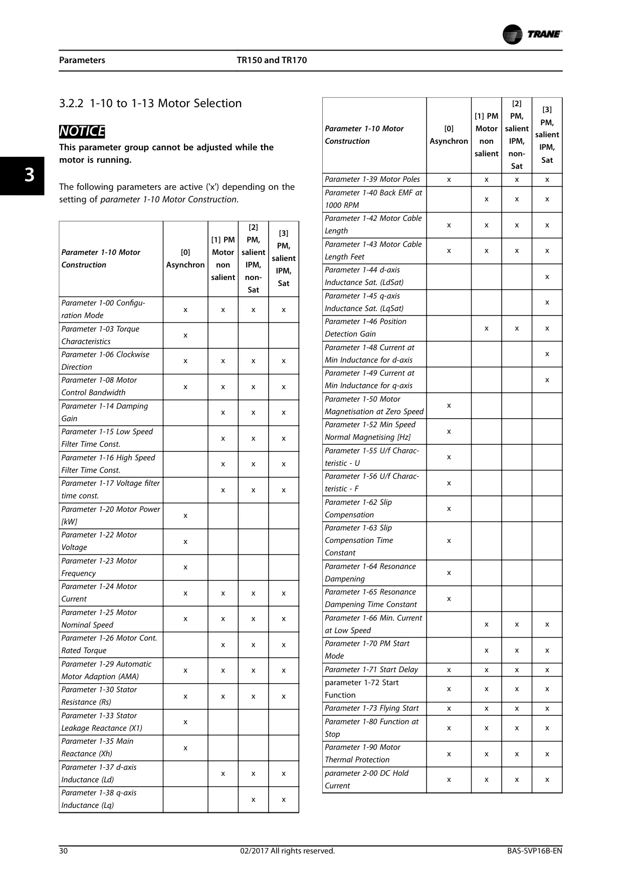
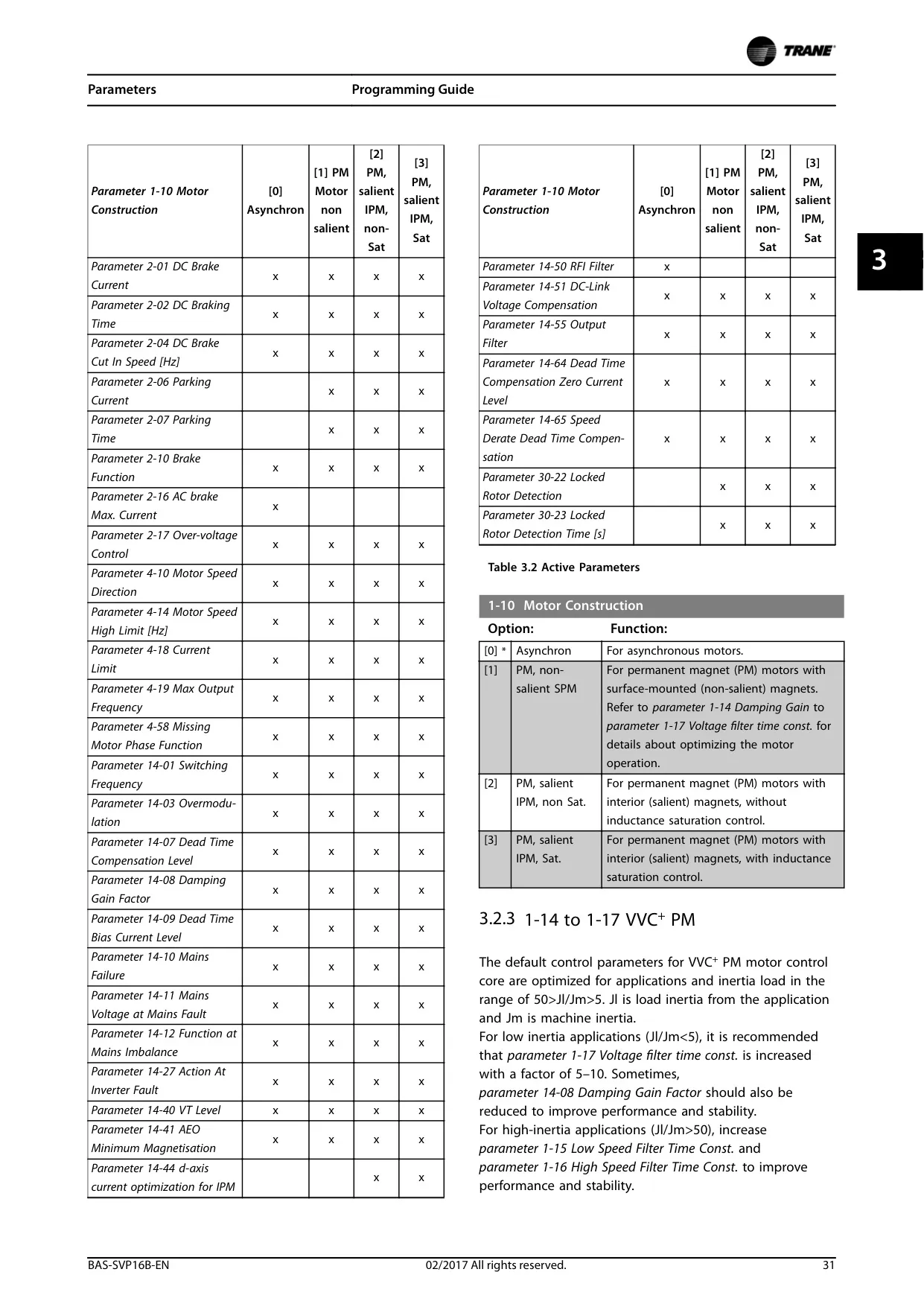
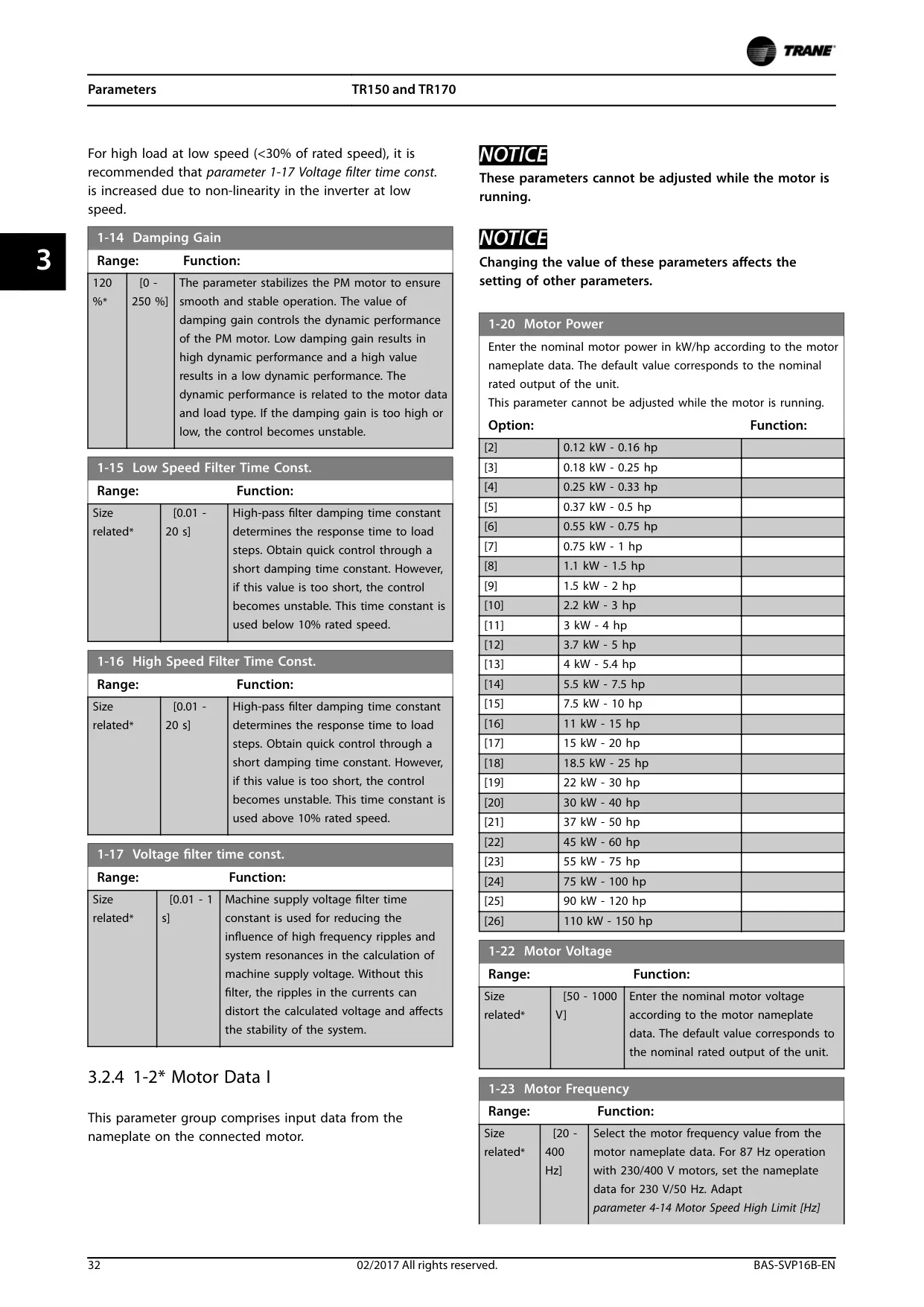
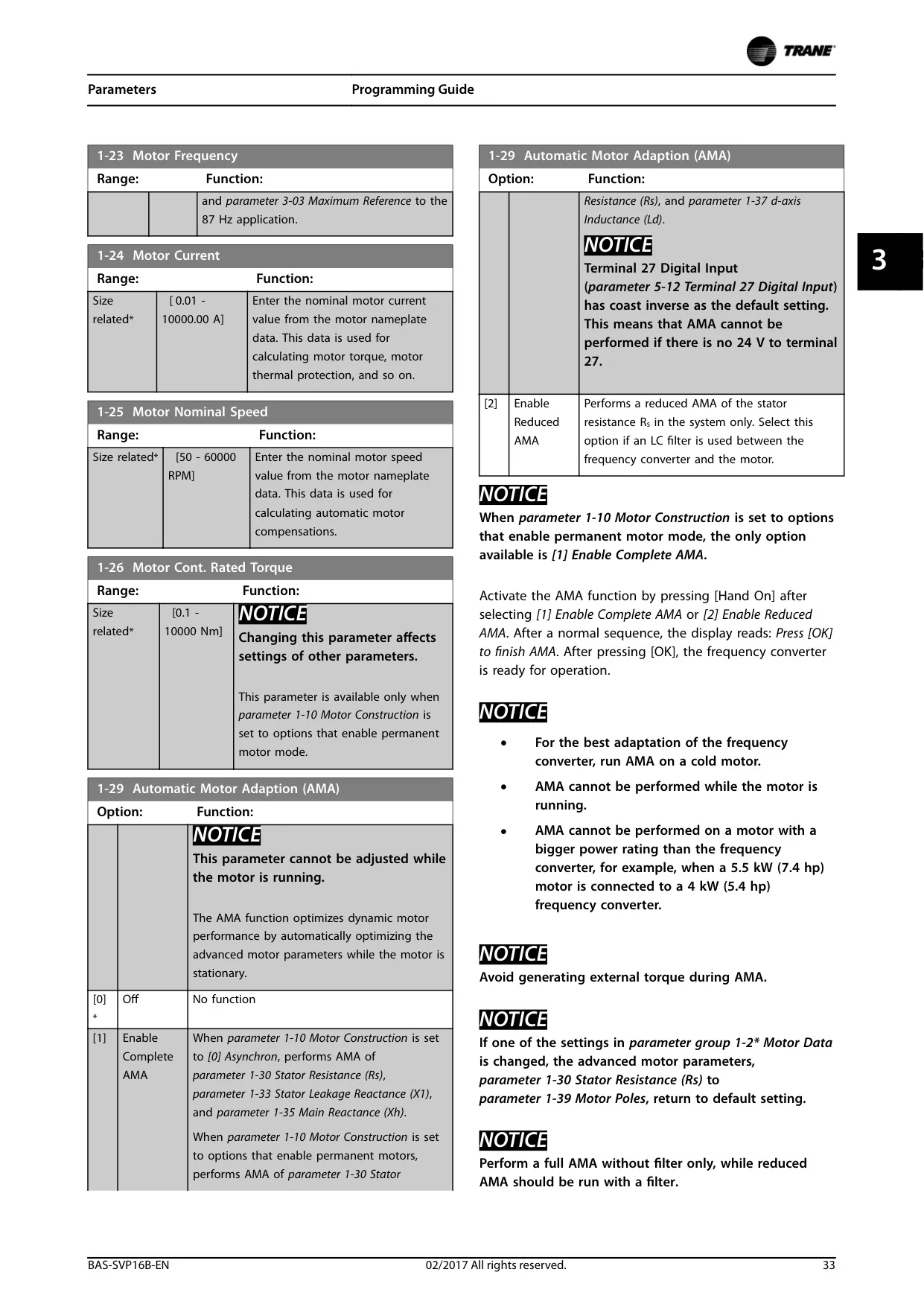
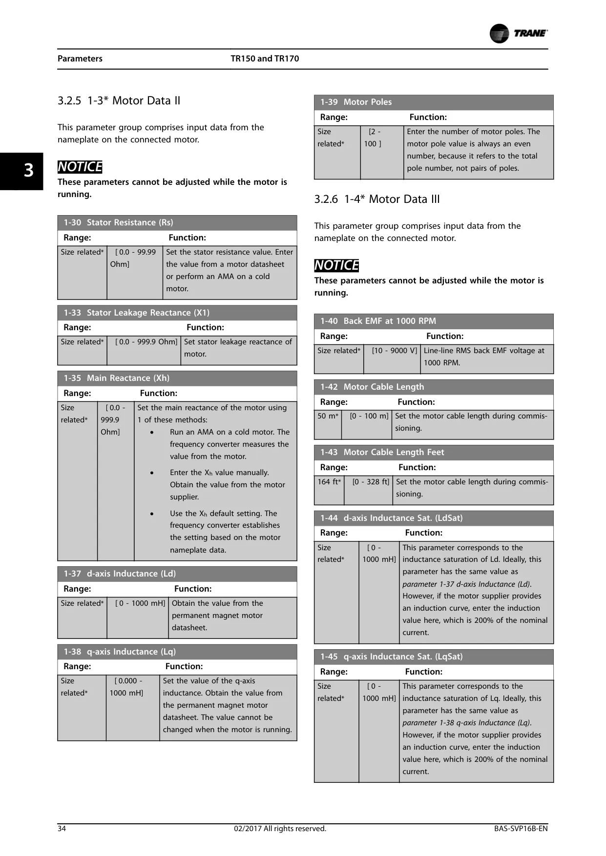
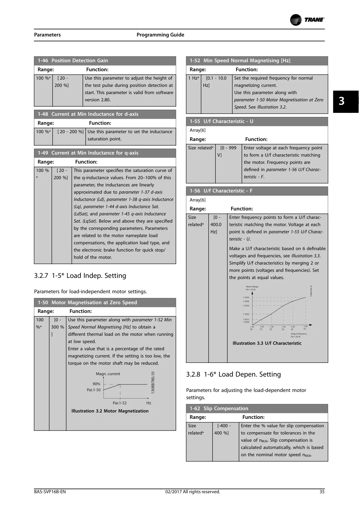
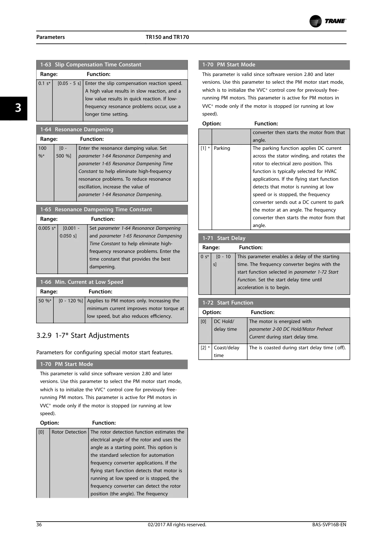

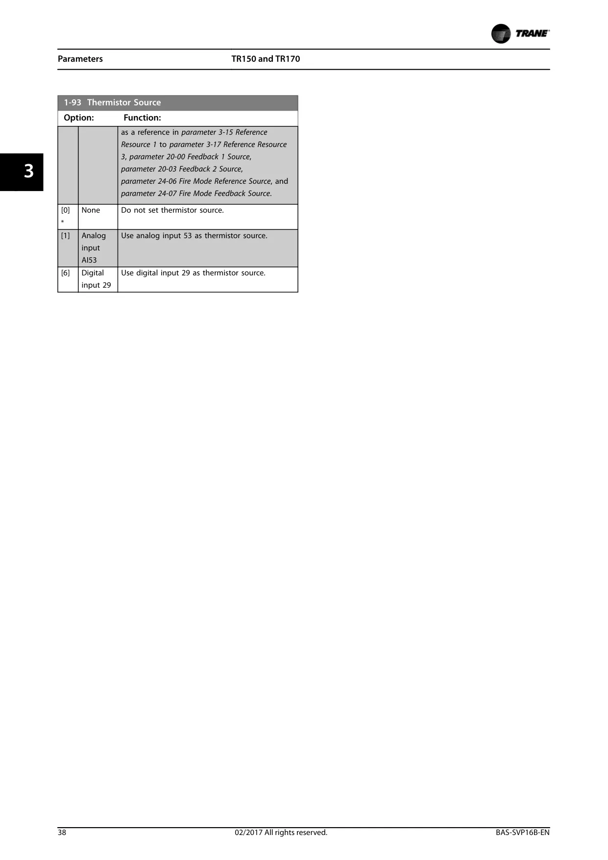









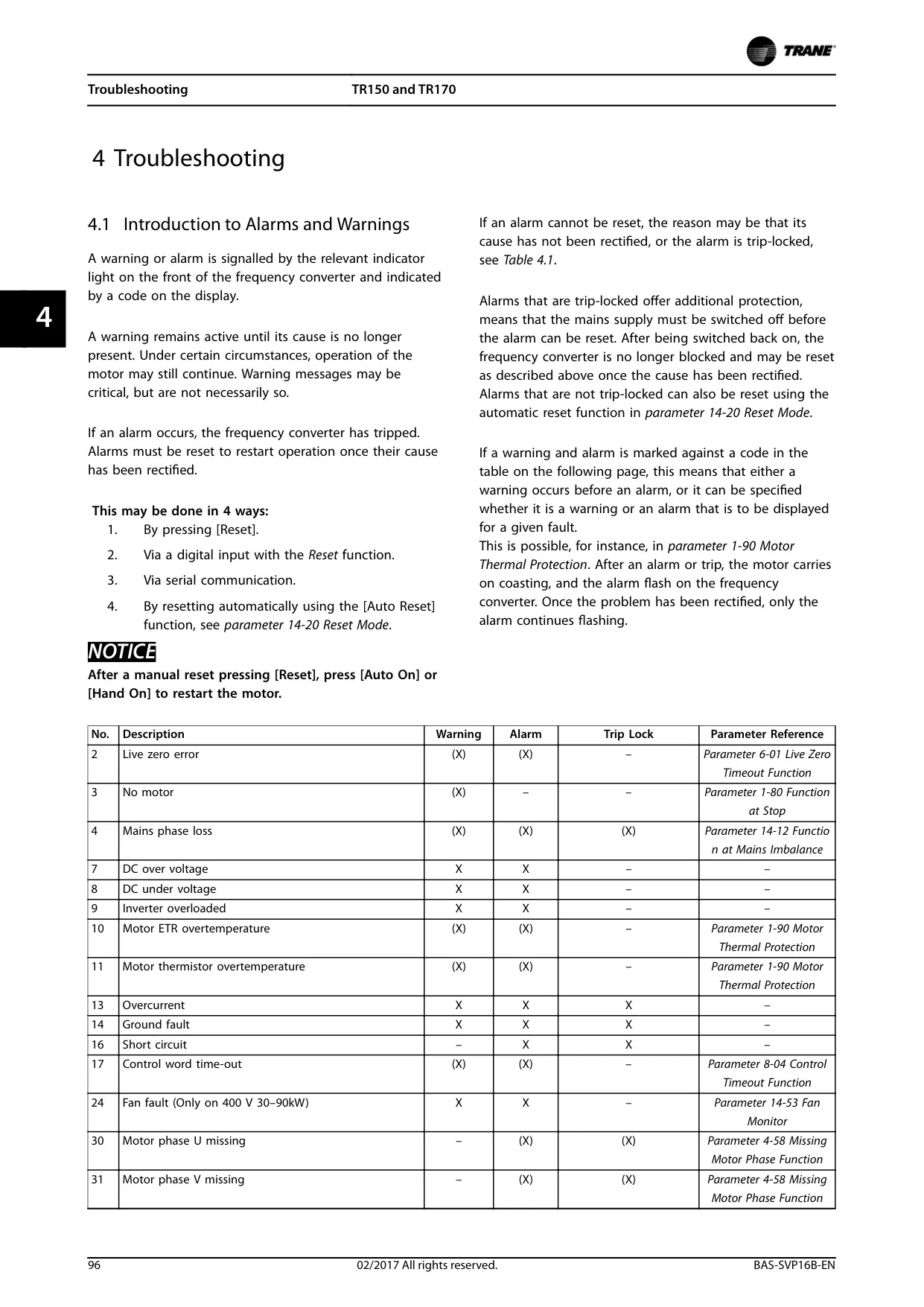

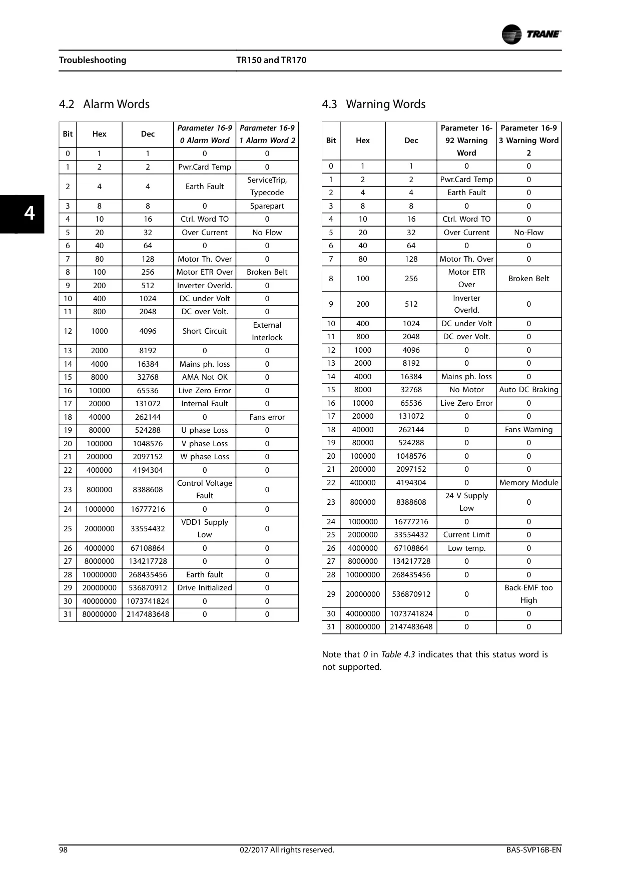
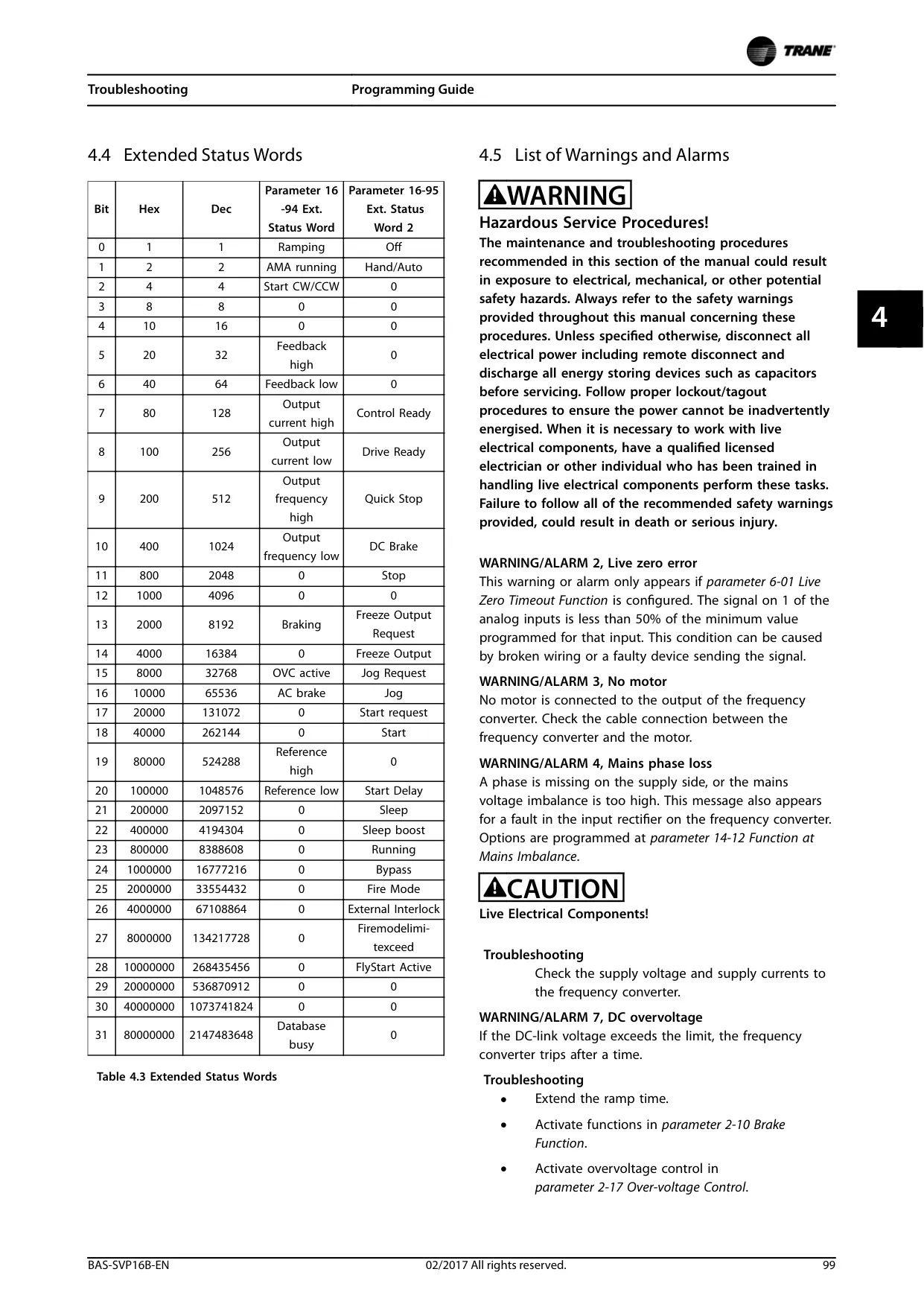
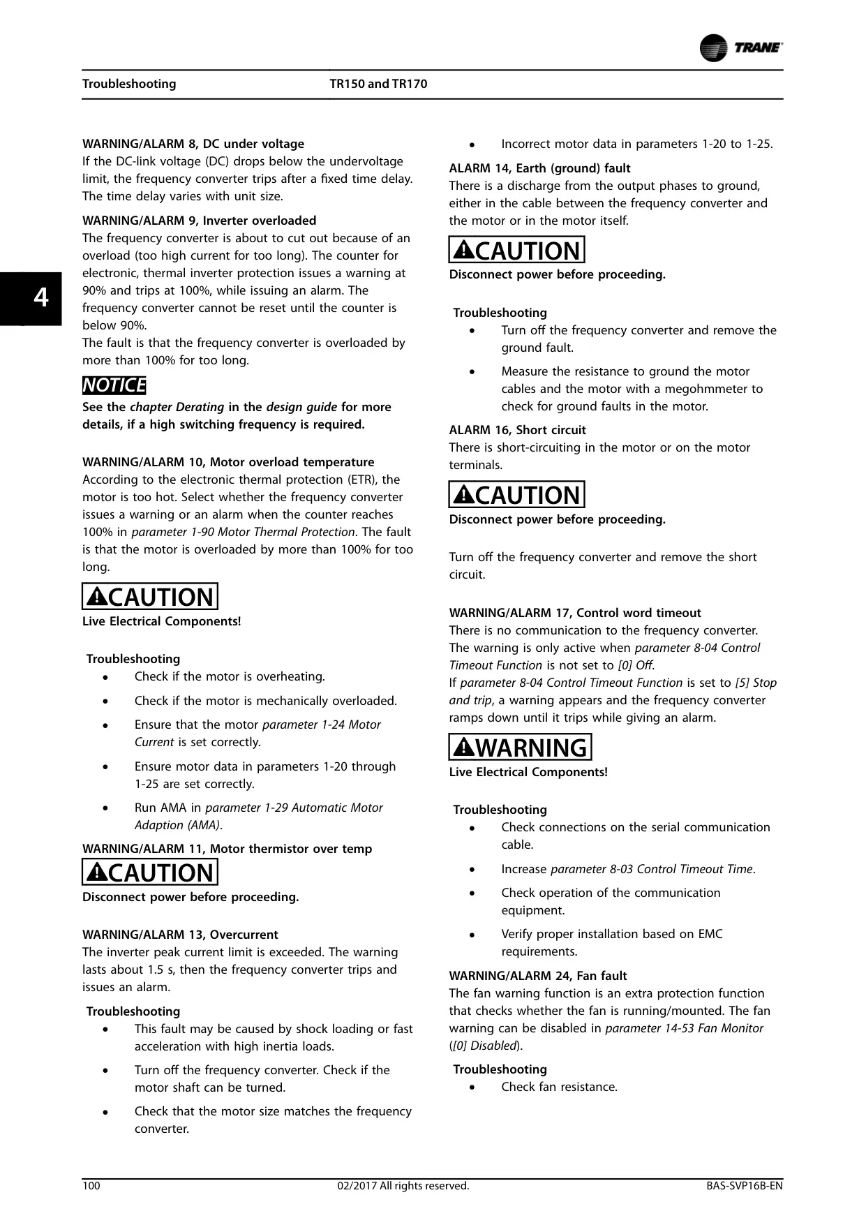



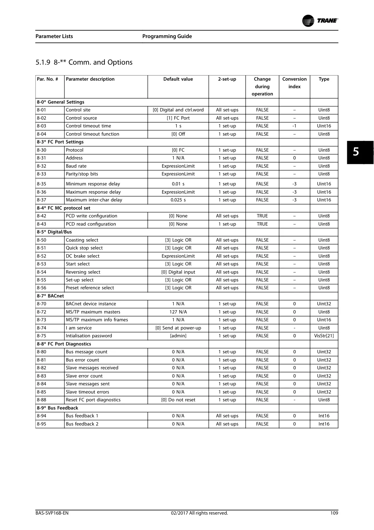
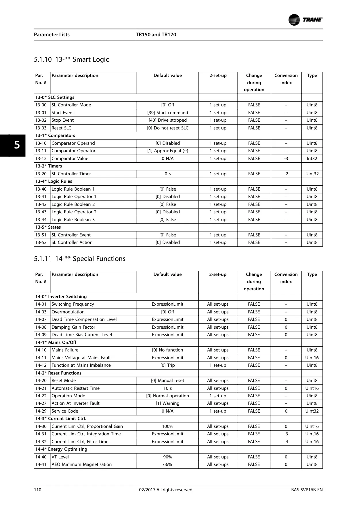
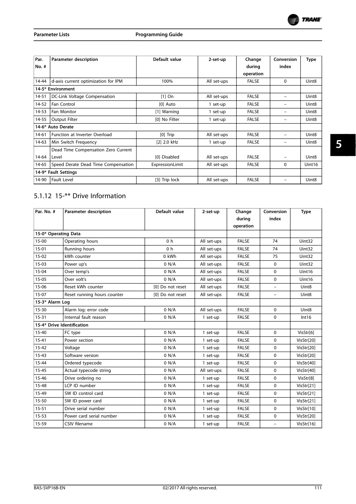
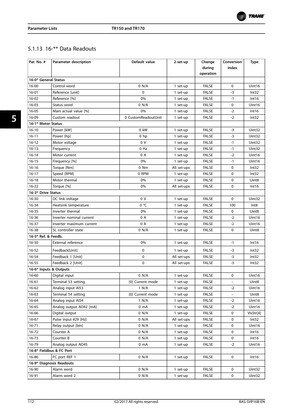





Trane TR170 Variable Frequency Drive
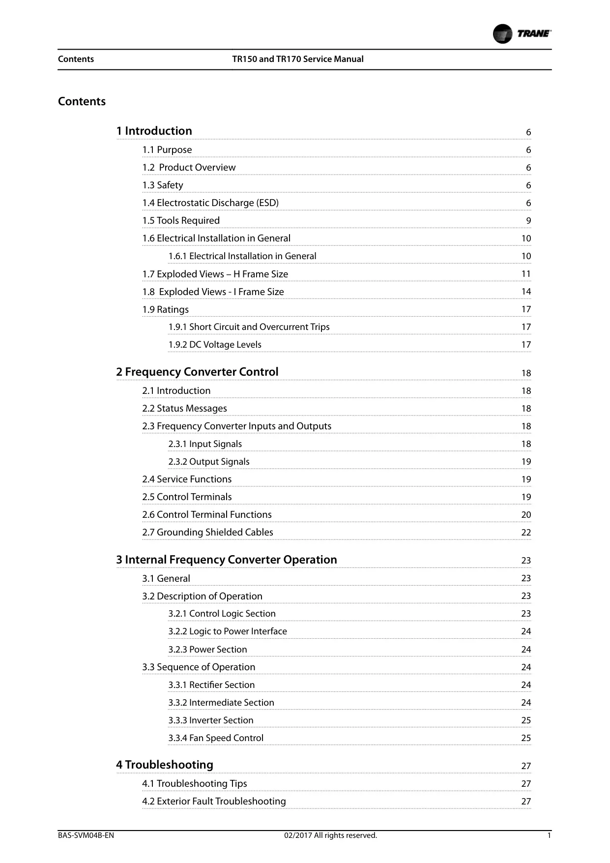
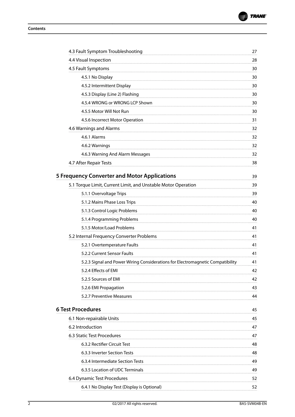
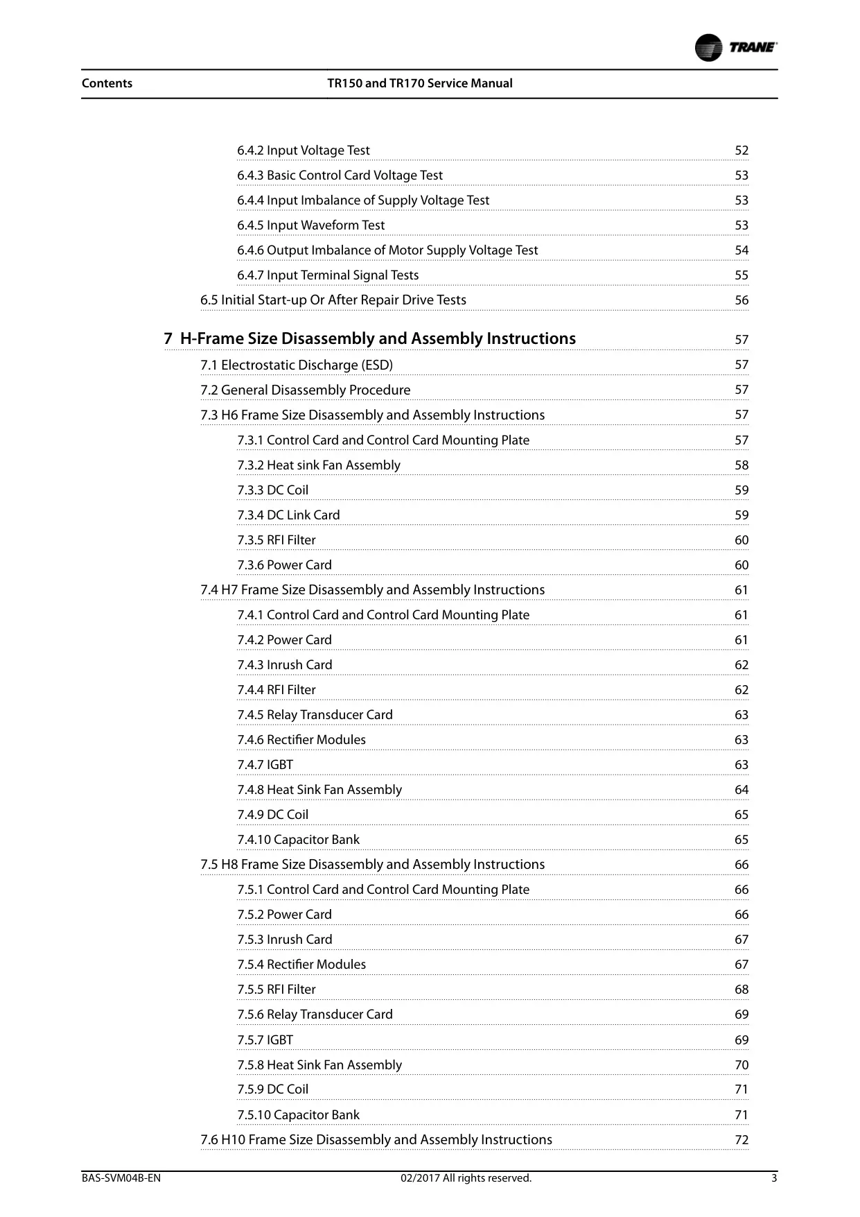
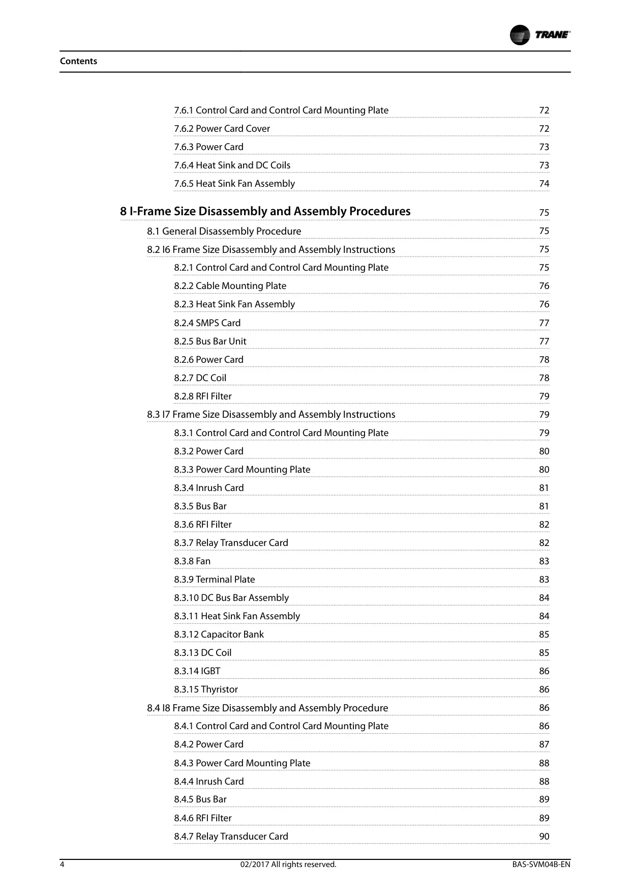

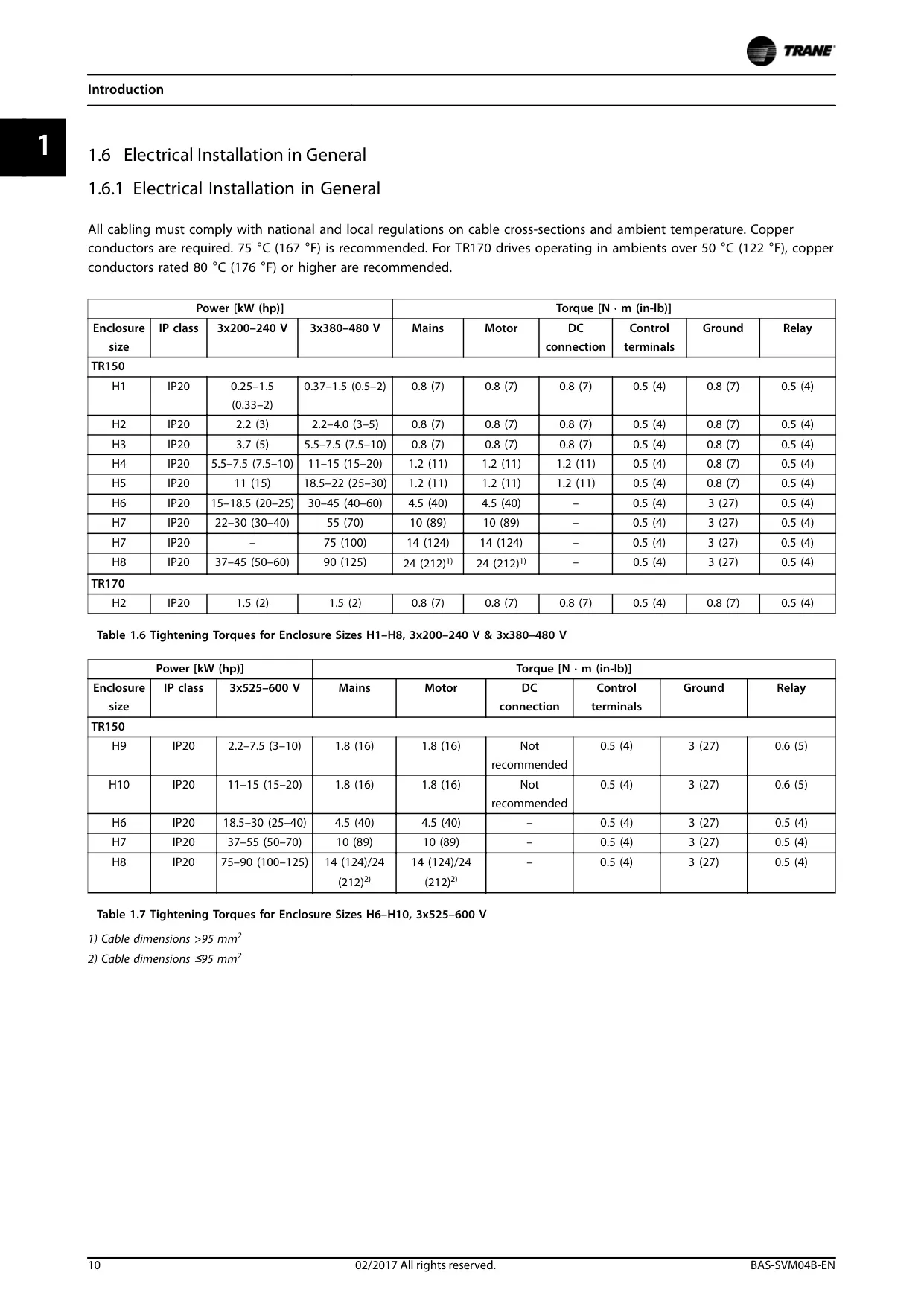
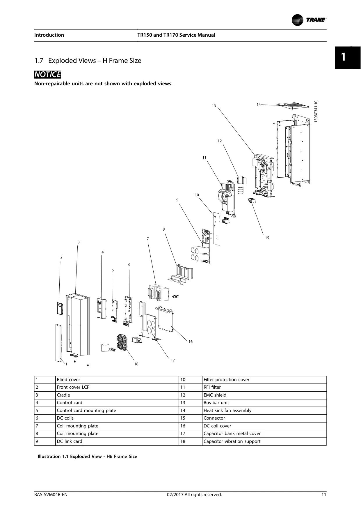
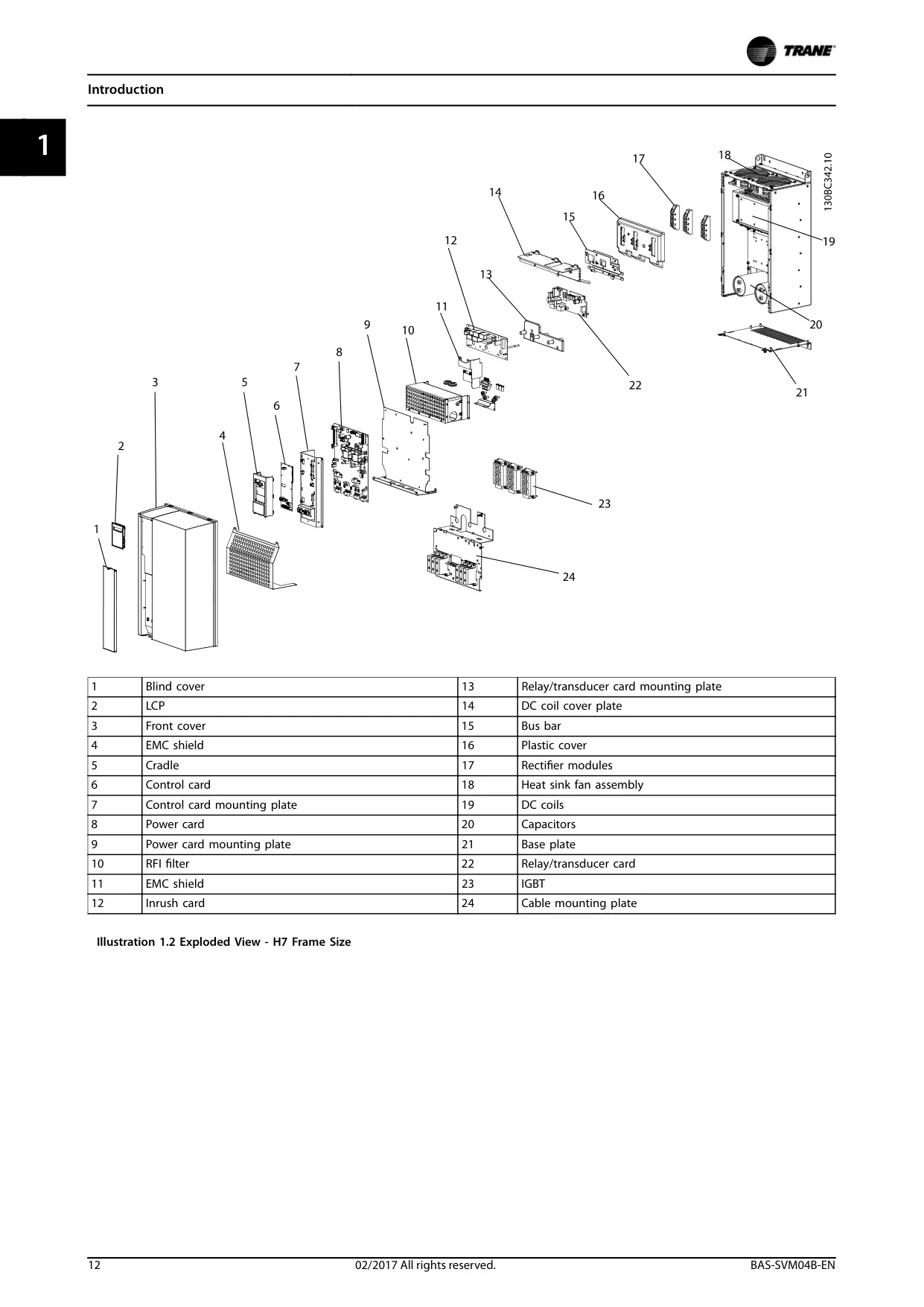
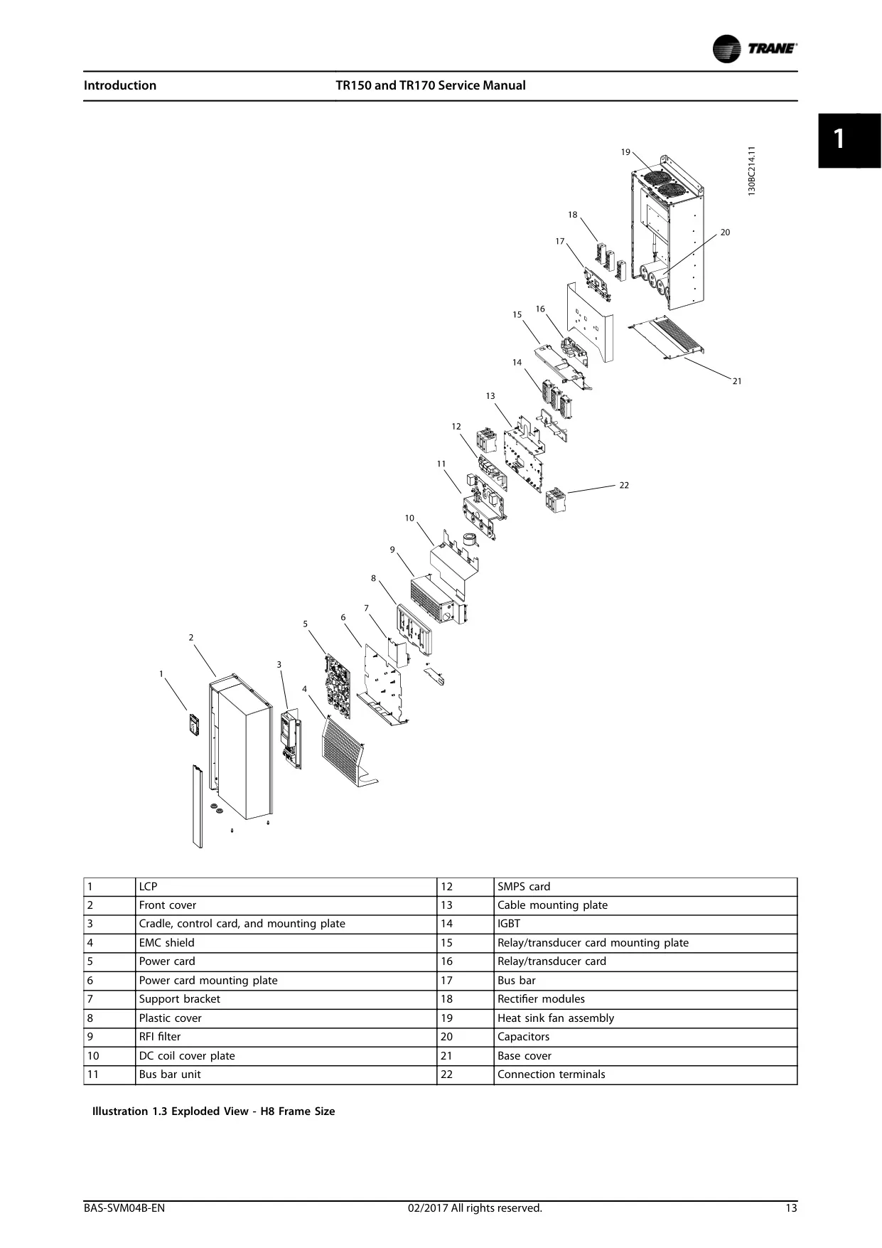
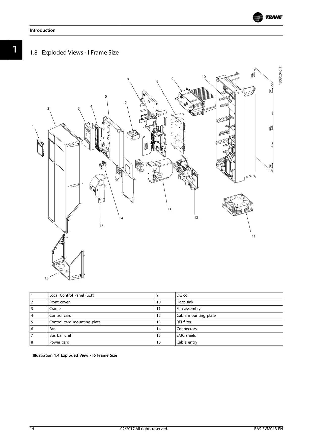
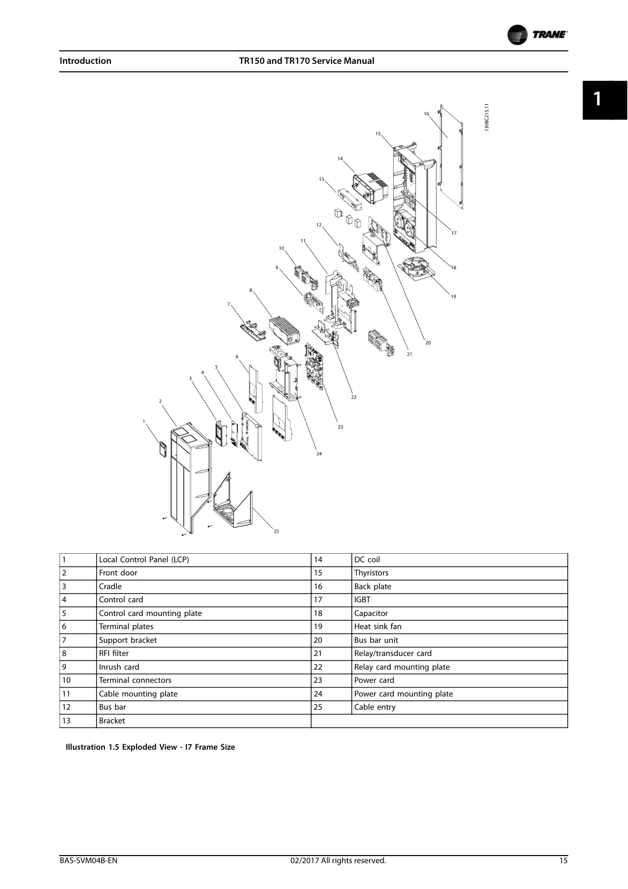
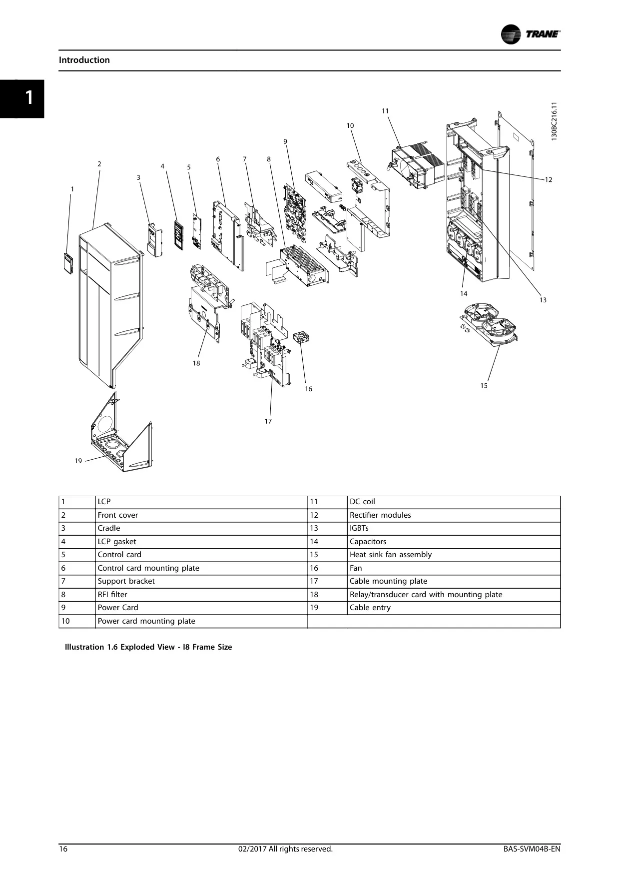
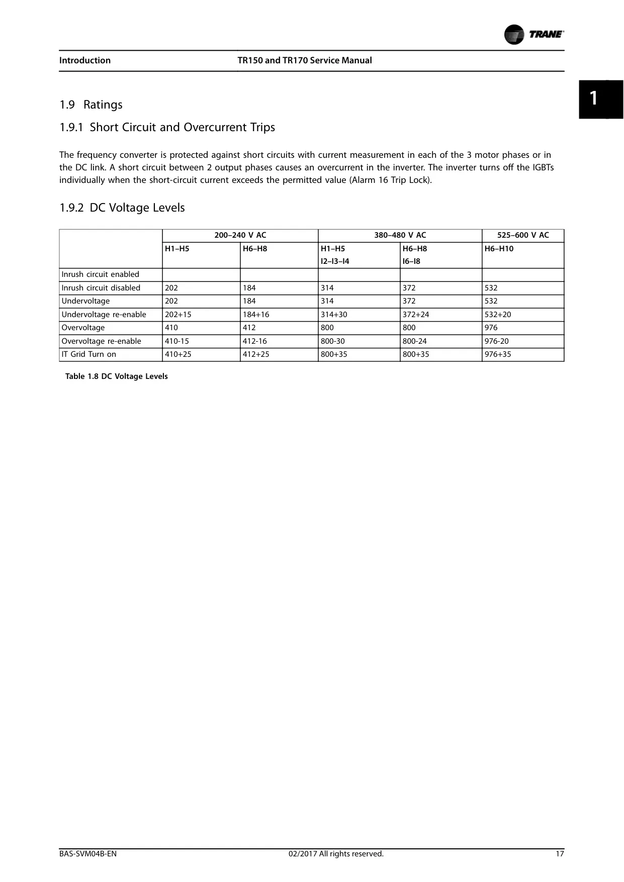


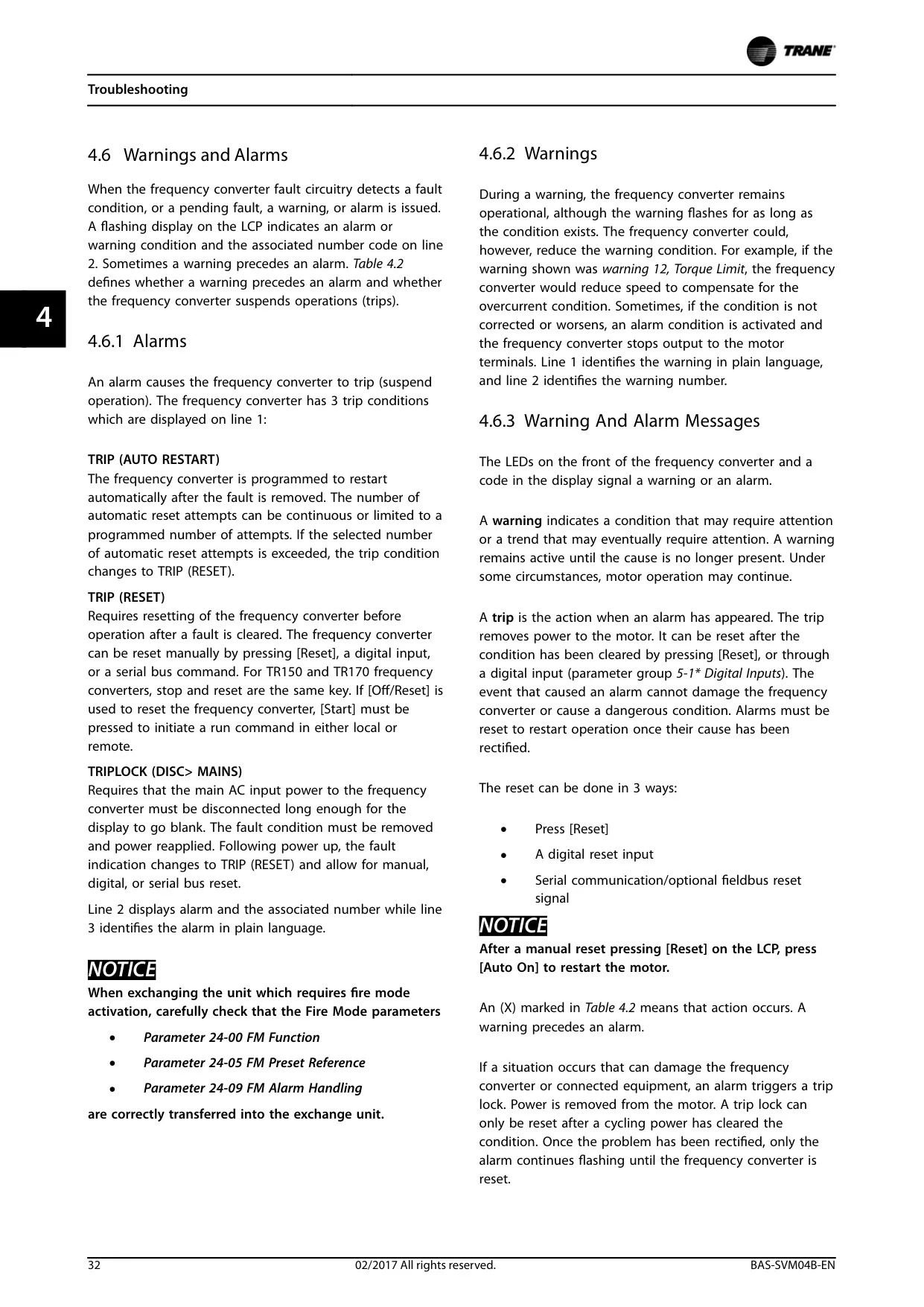
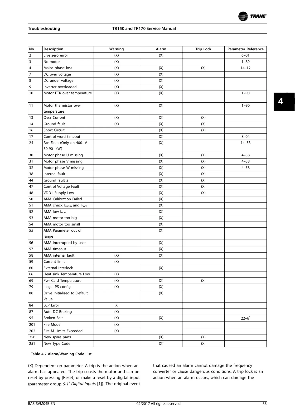
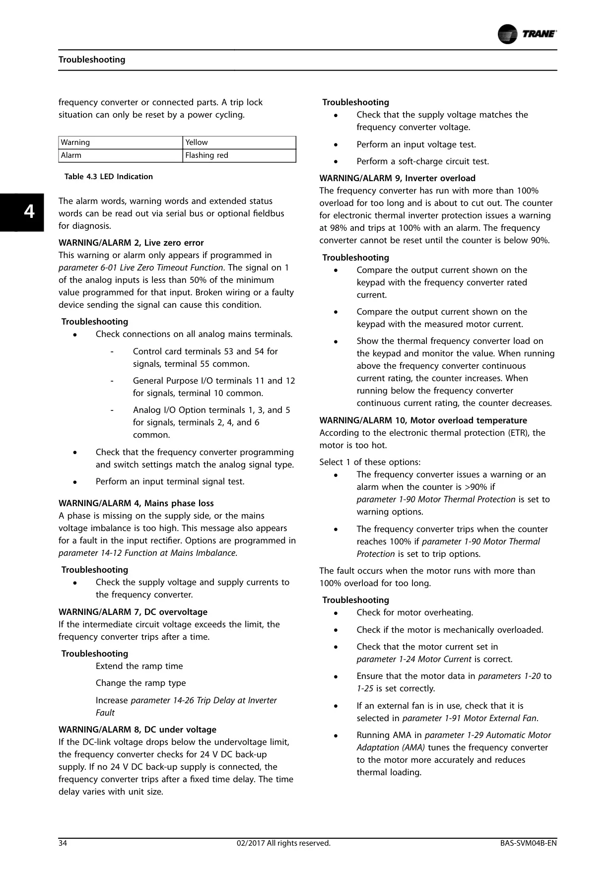
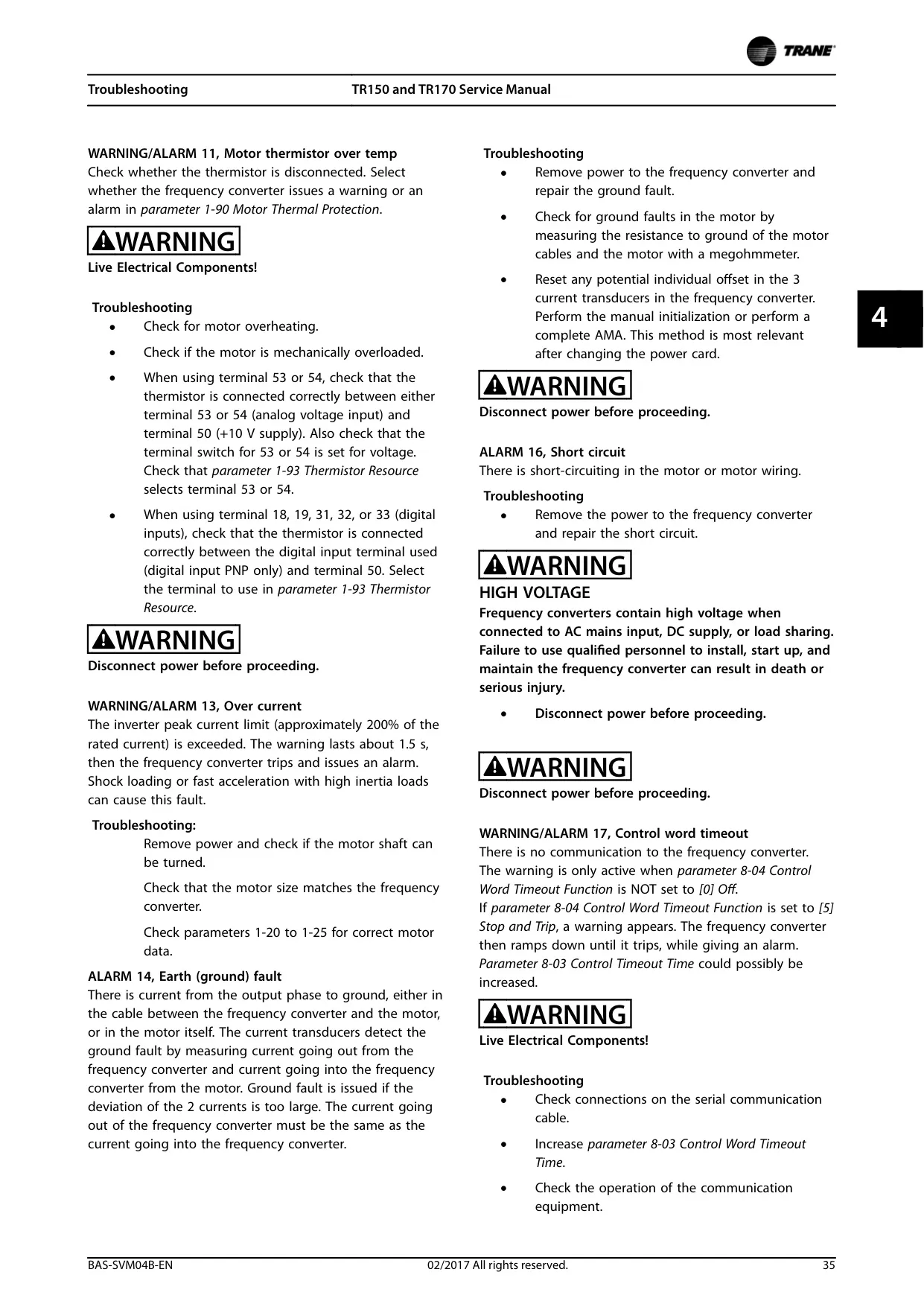
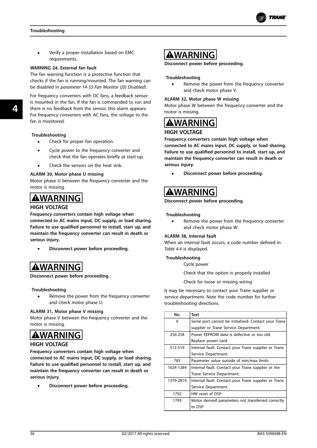
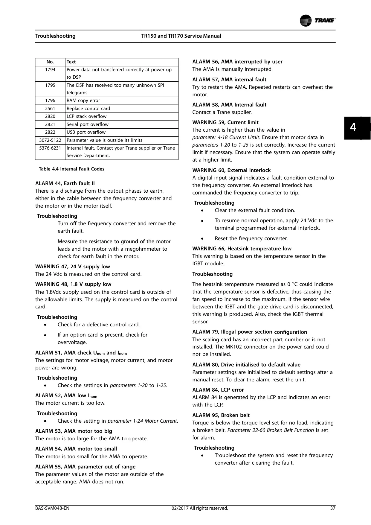
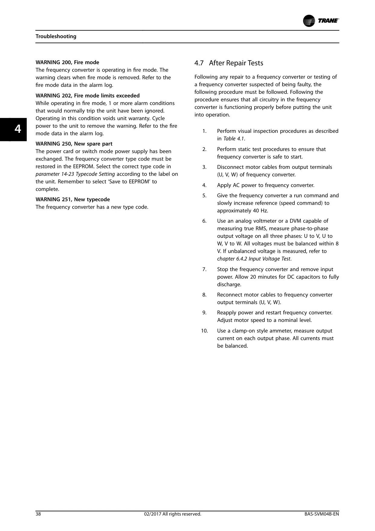
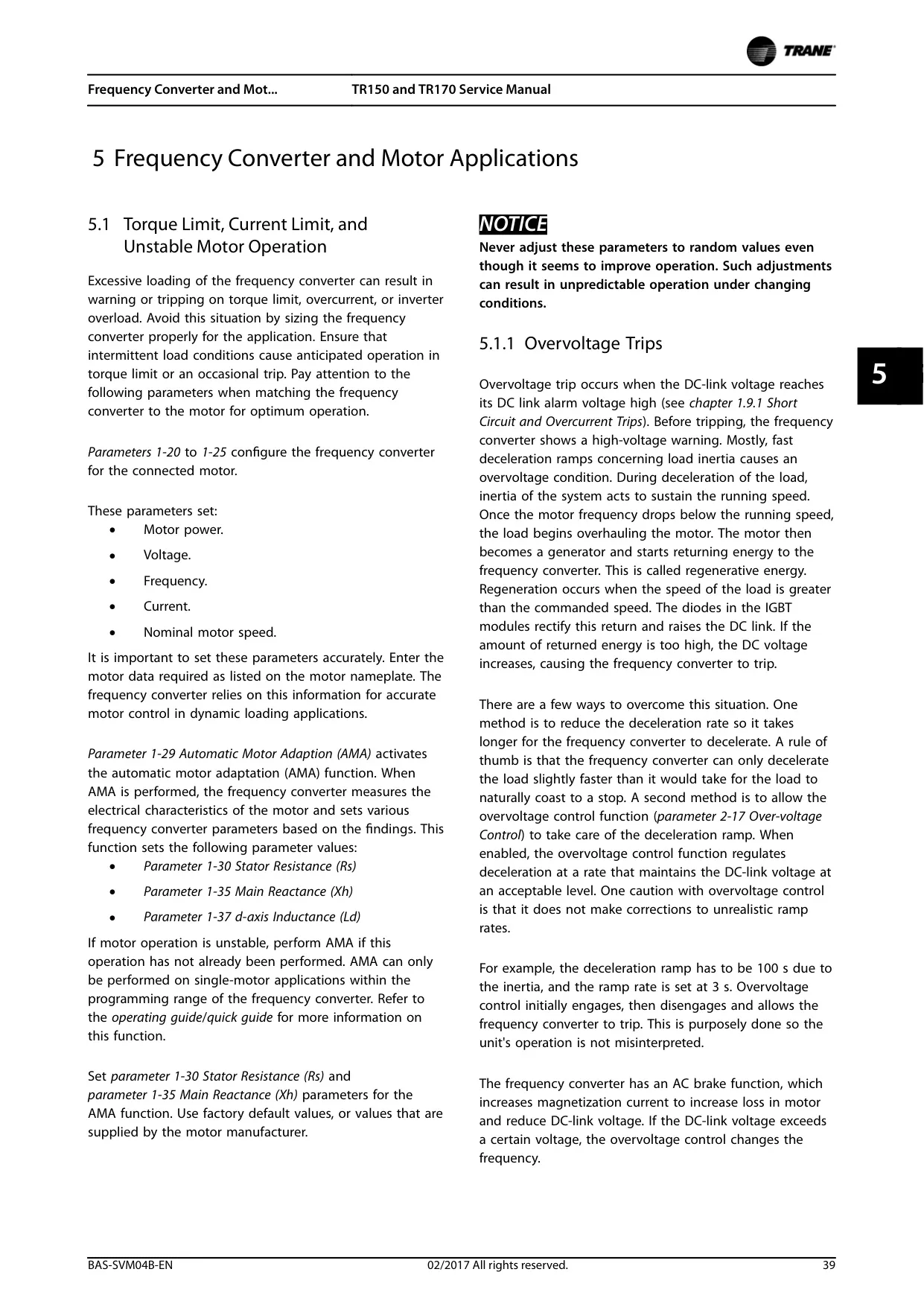
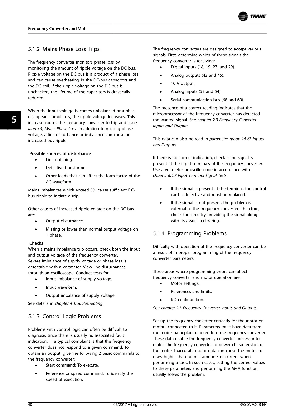
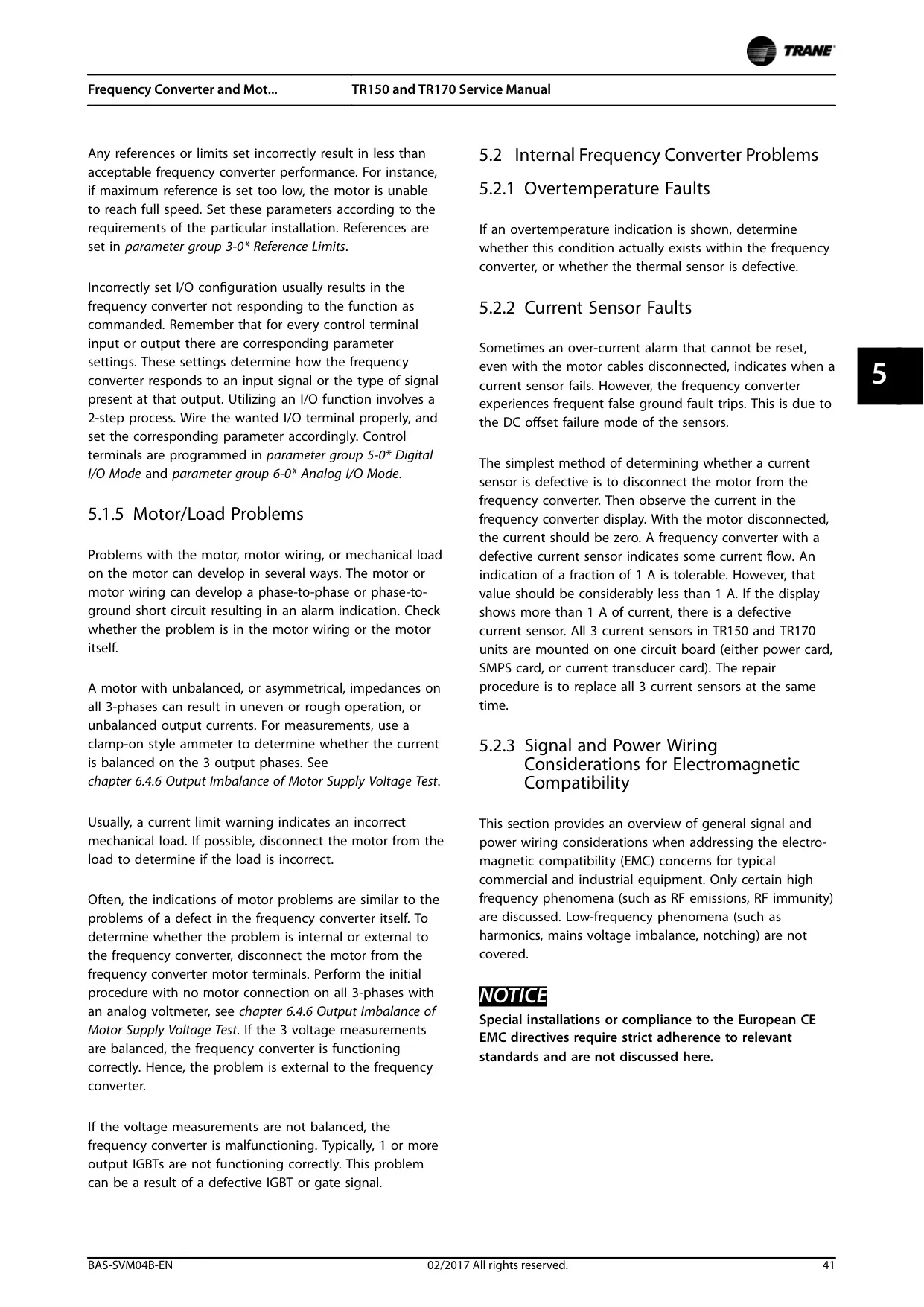
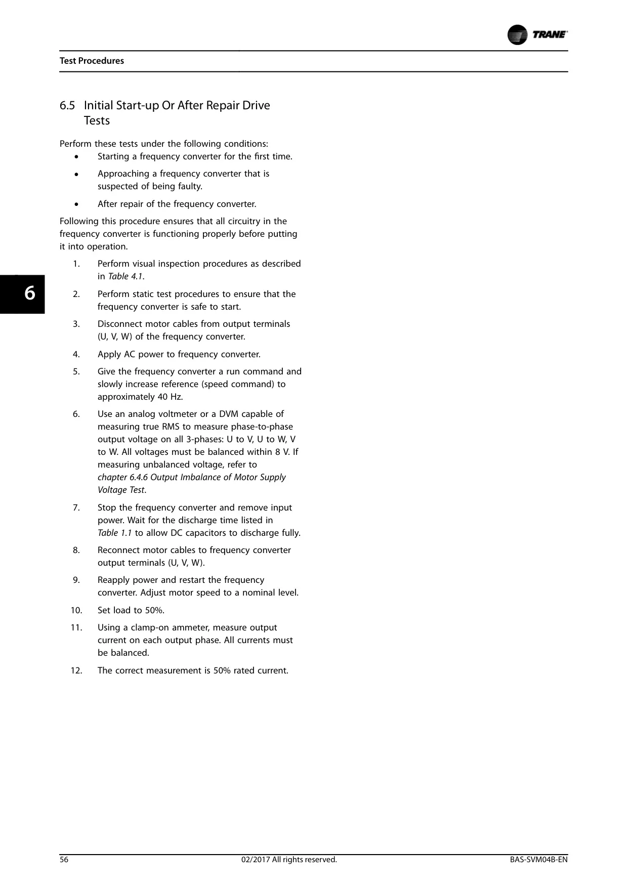
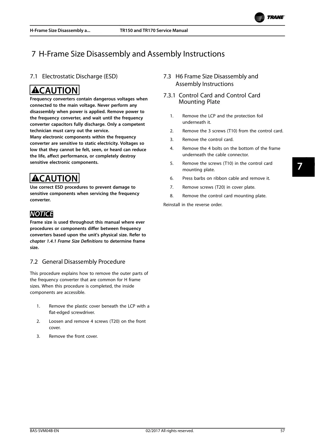
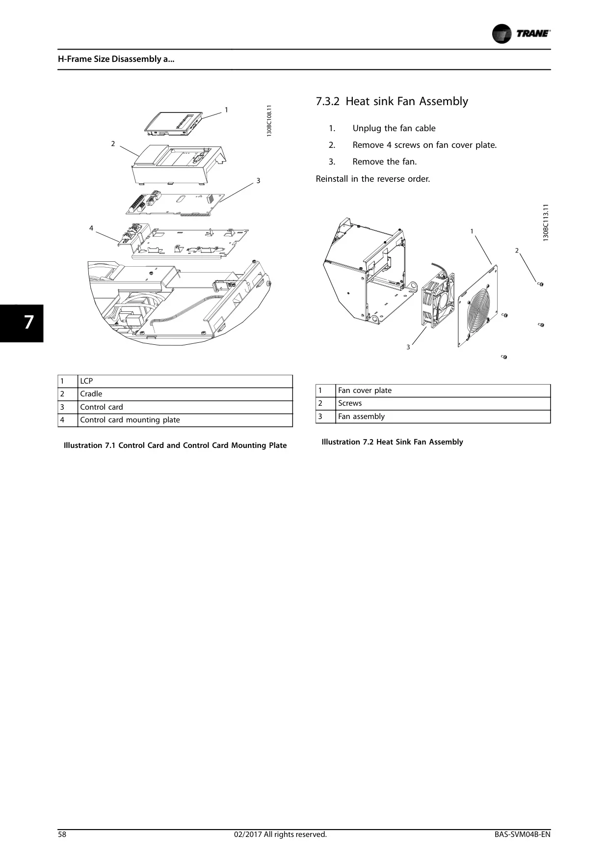
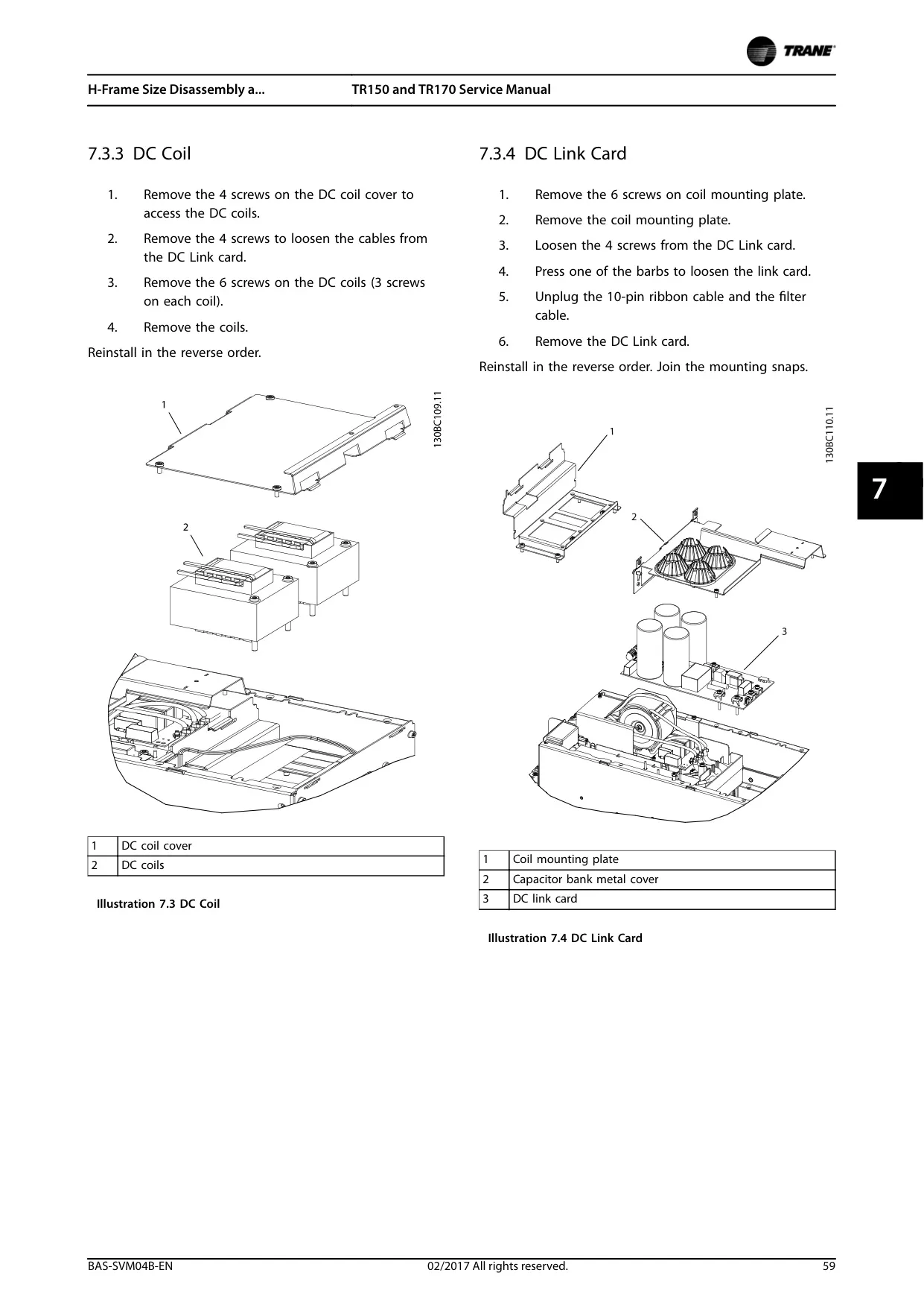
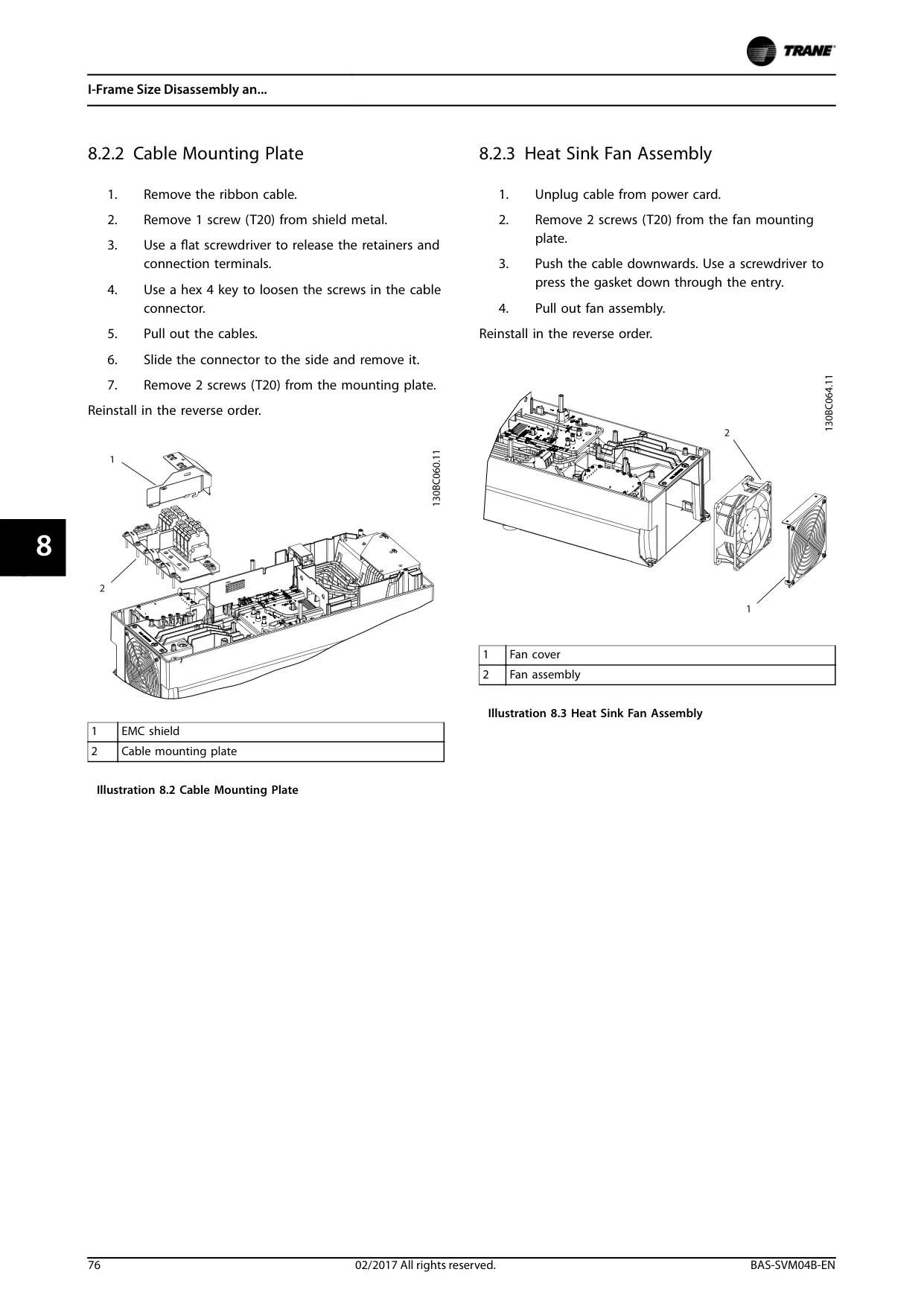
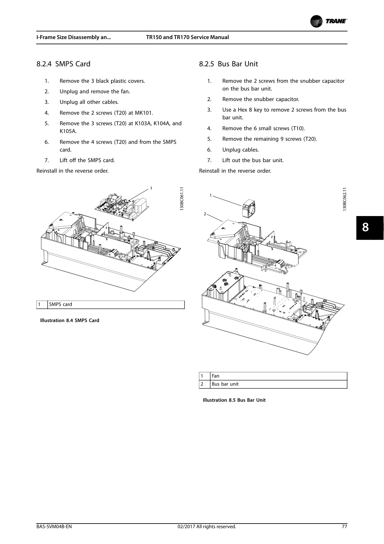
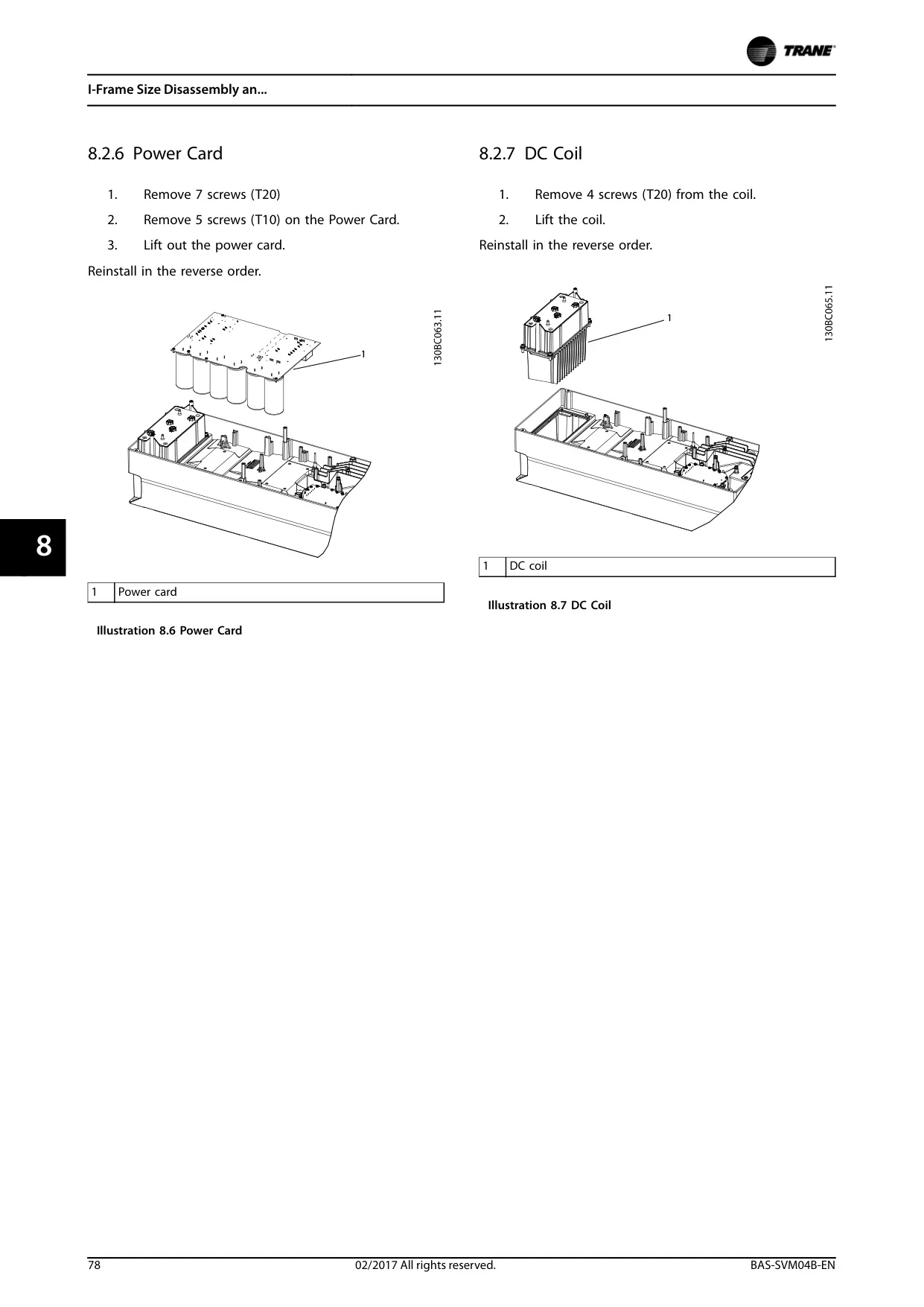
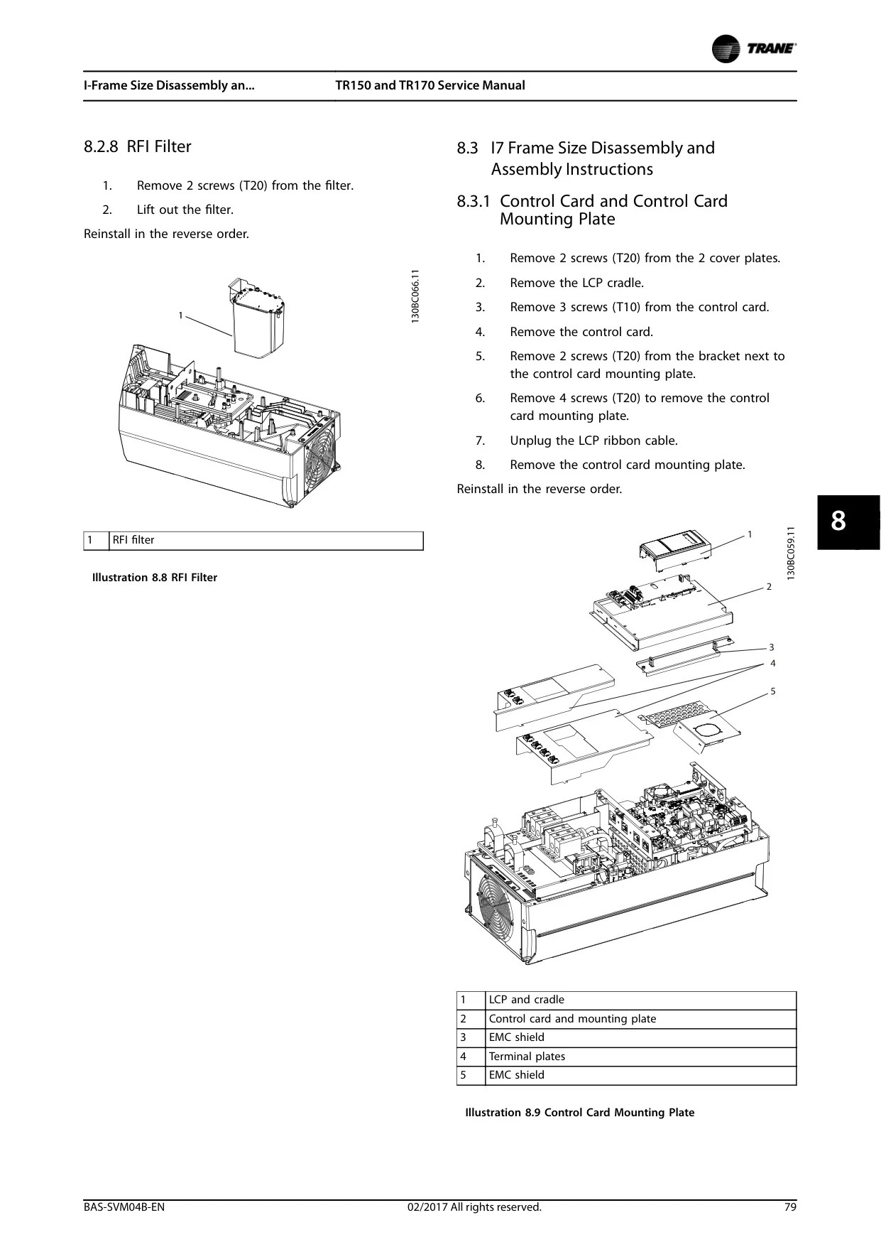
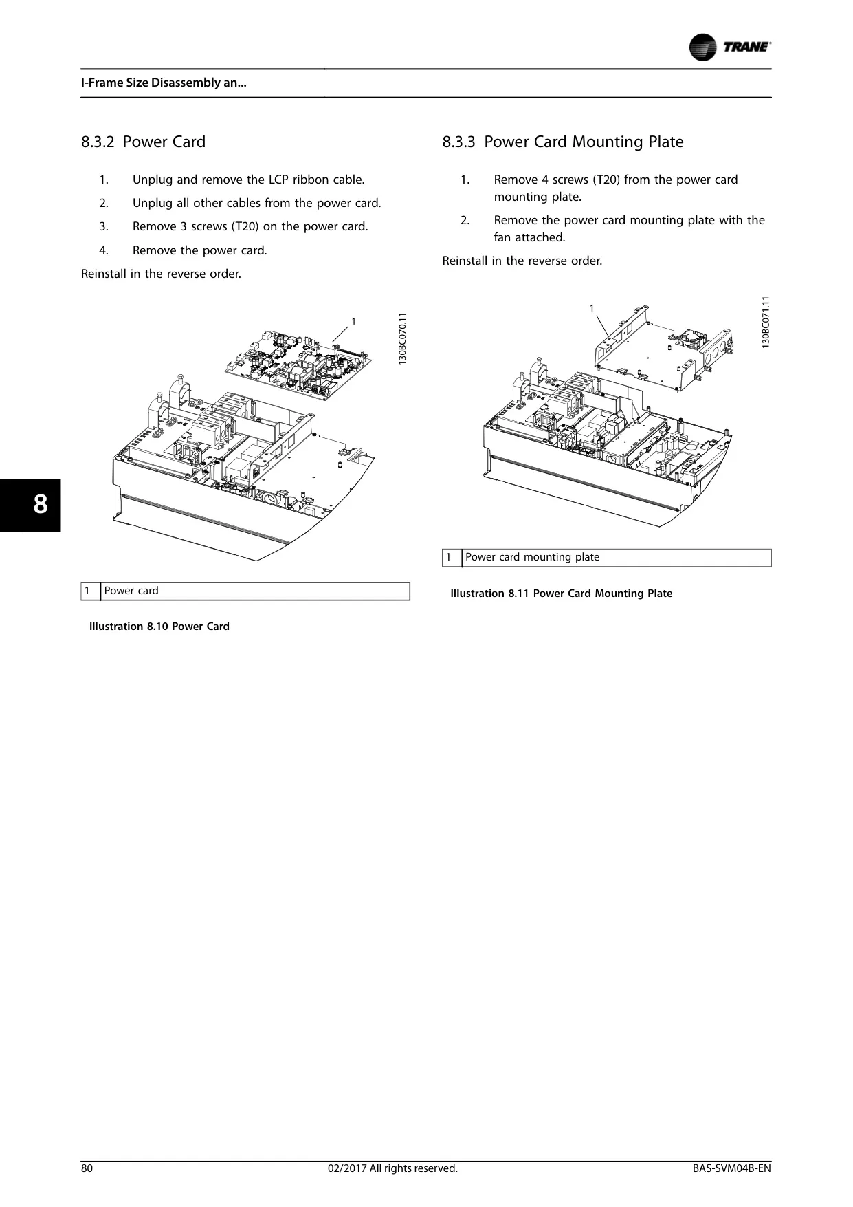
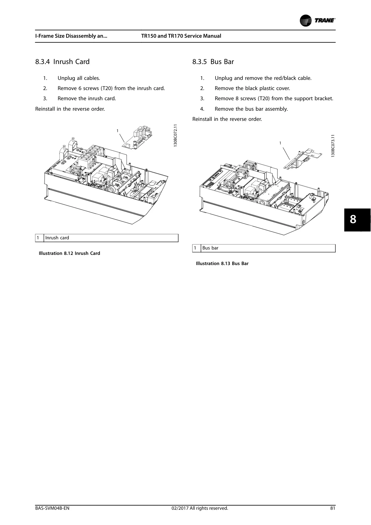
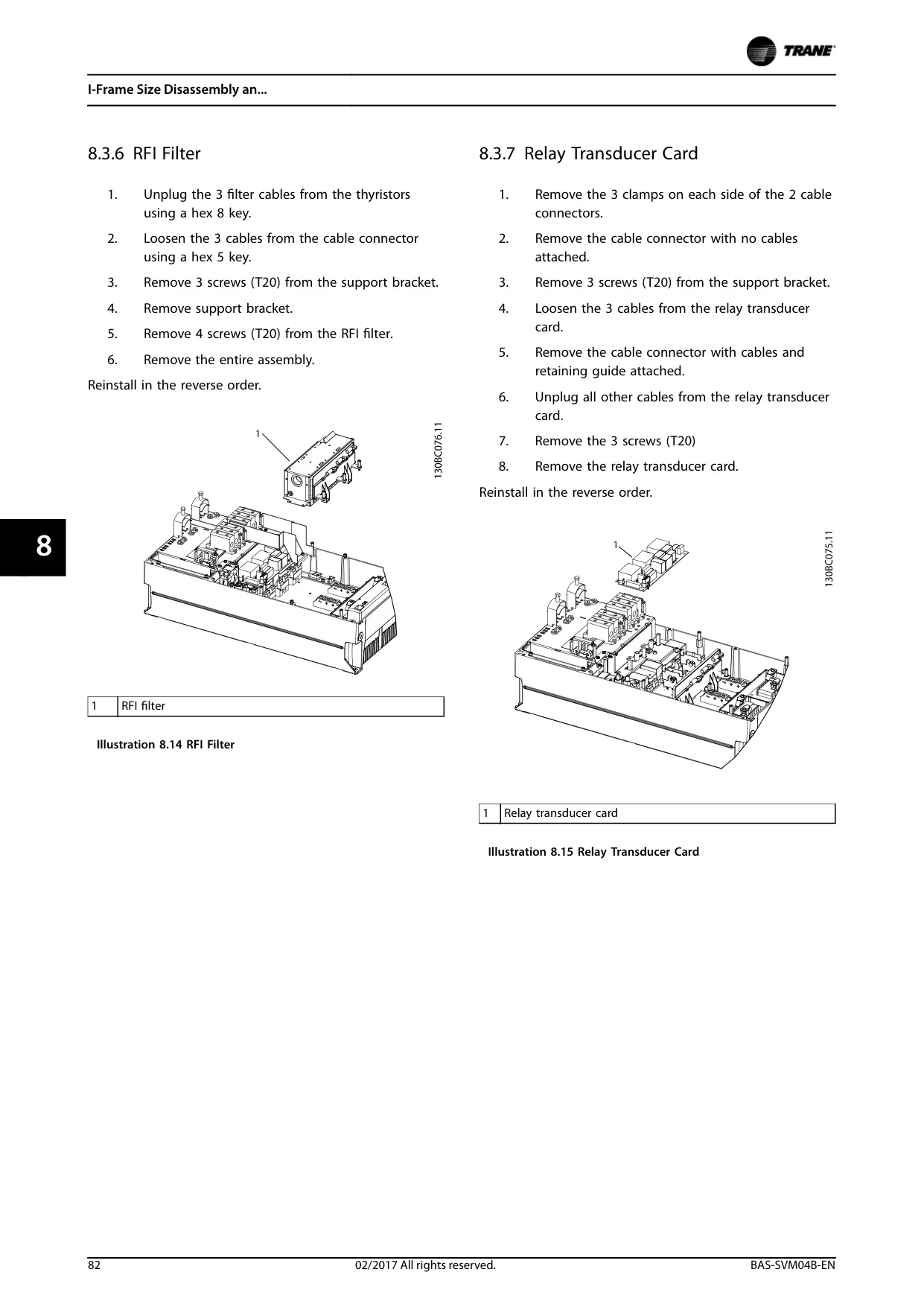
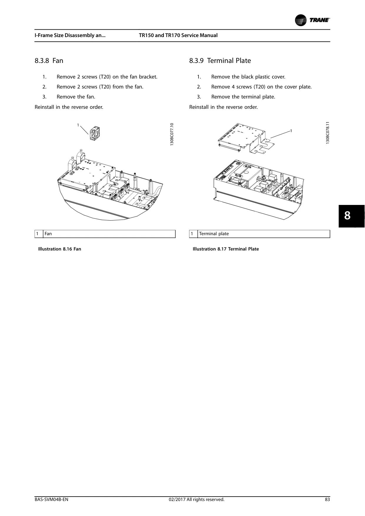
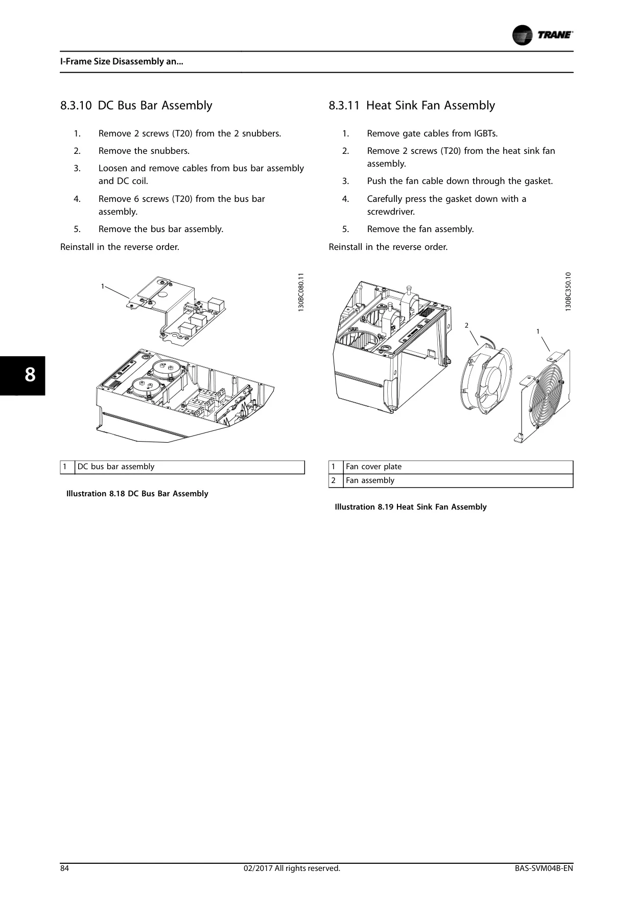
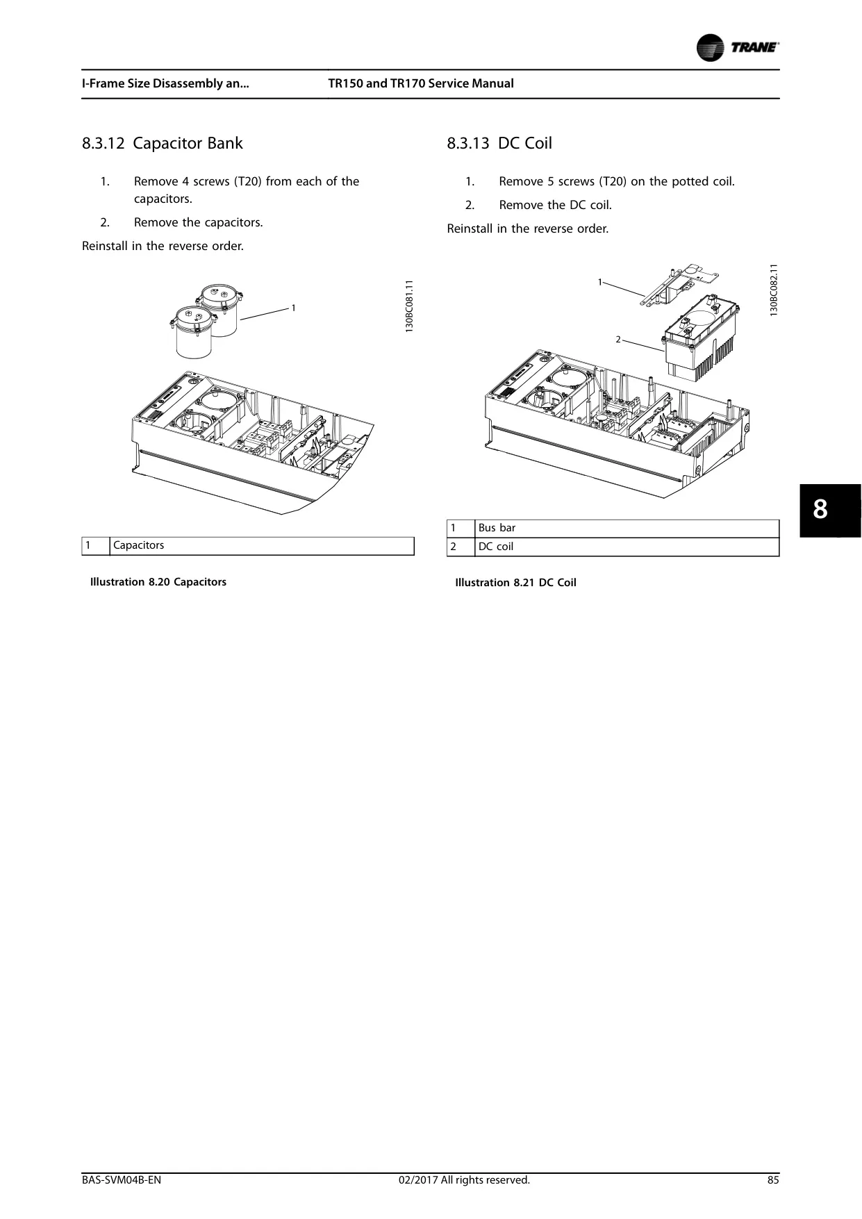
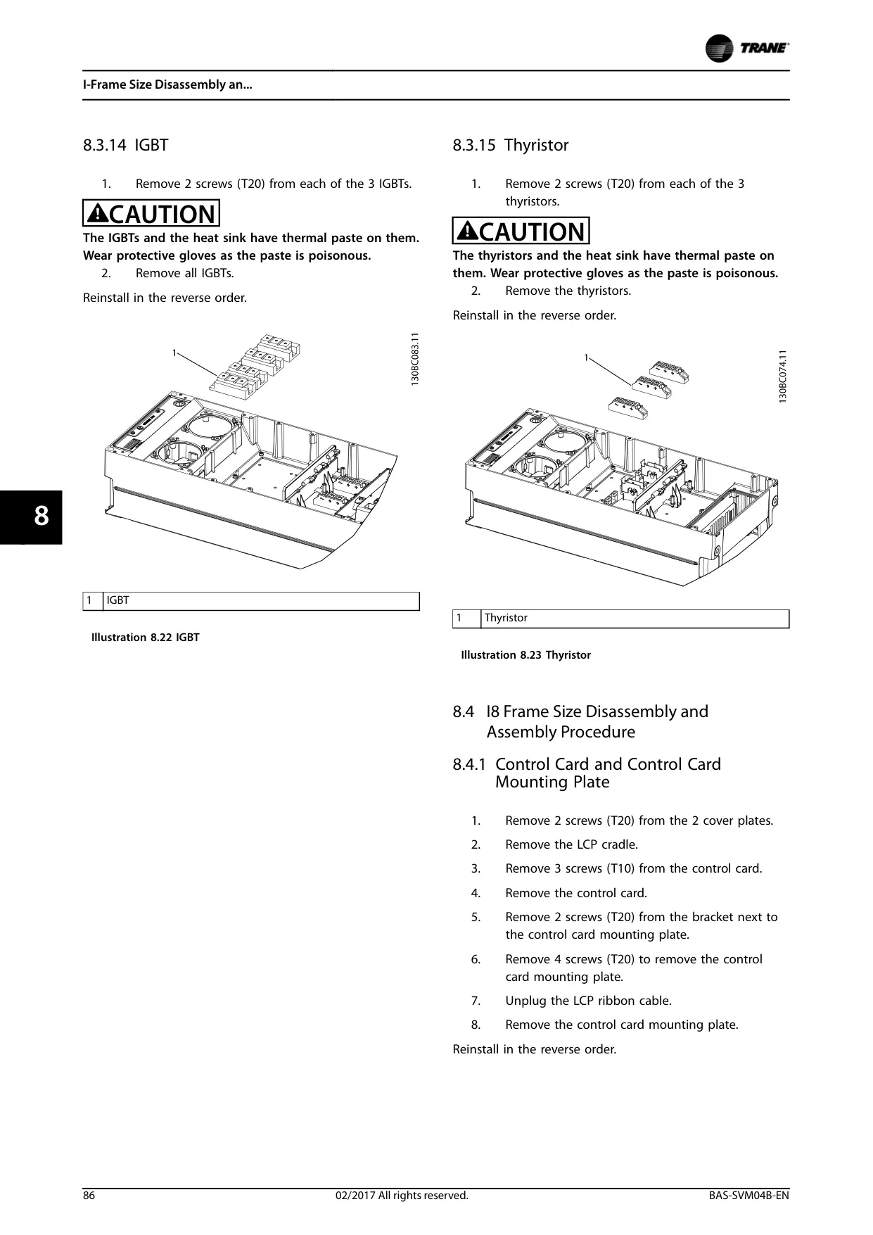
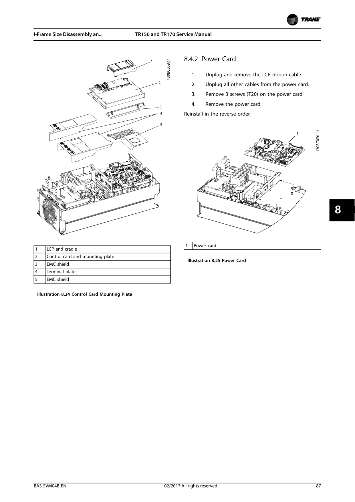
Trane TR170 VFD Instructions
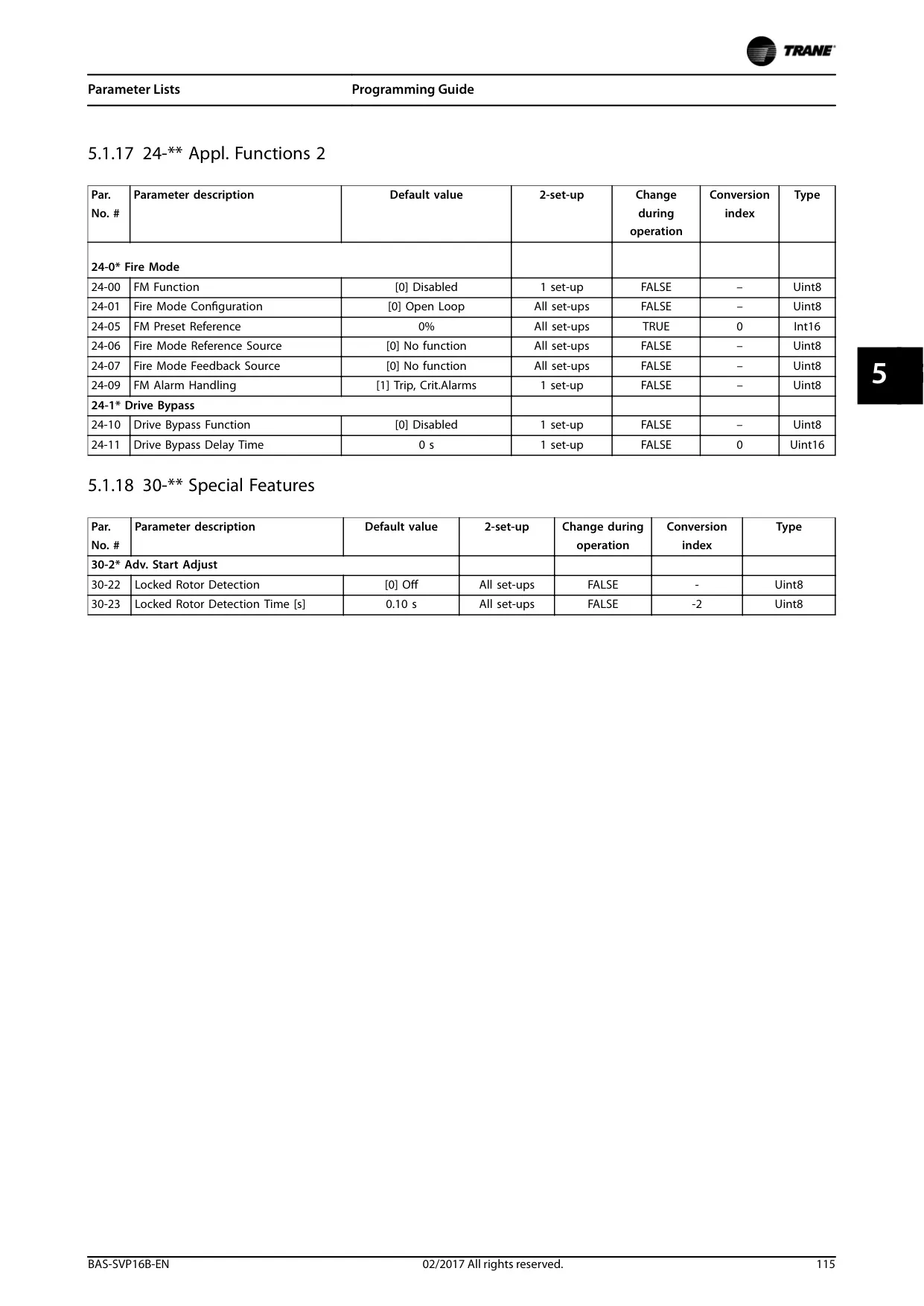
Here we offer the Trane TR170 Variable Frequency Drive manual completely free and in English. We have cataloged this manual in the Variable Frequency Drives section on Manualverse, and it has been rated by 1 users with an average rating of 5. If you have any specific questions about Trane TR170 Variable Frequency Drive, we suggest checking the Frequently Asked Questions (FAQs) section of this manual.
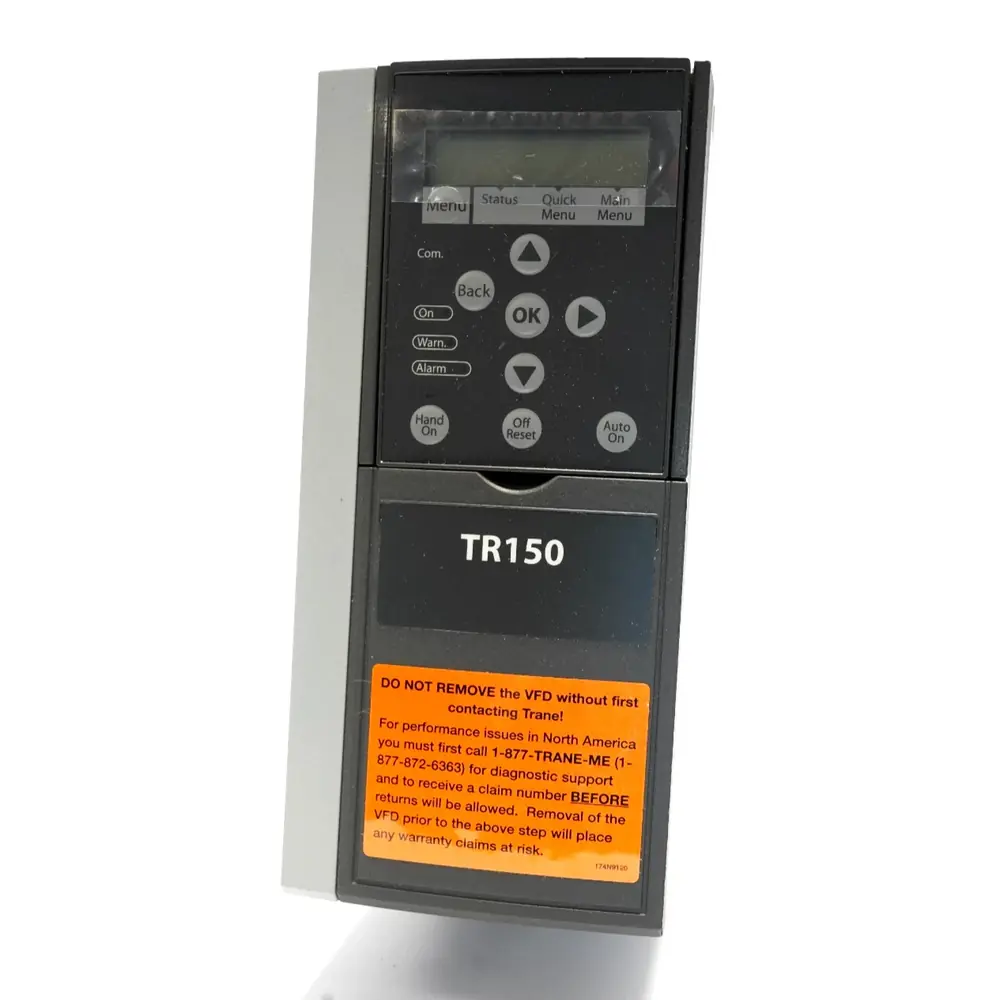
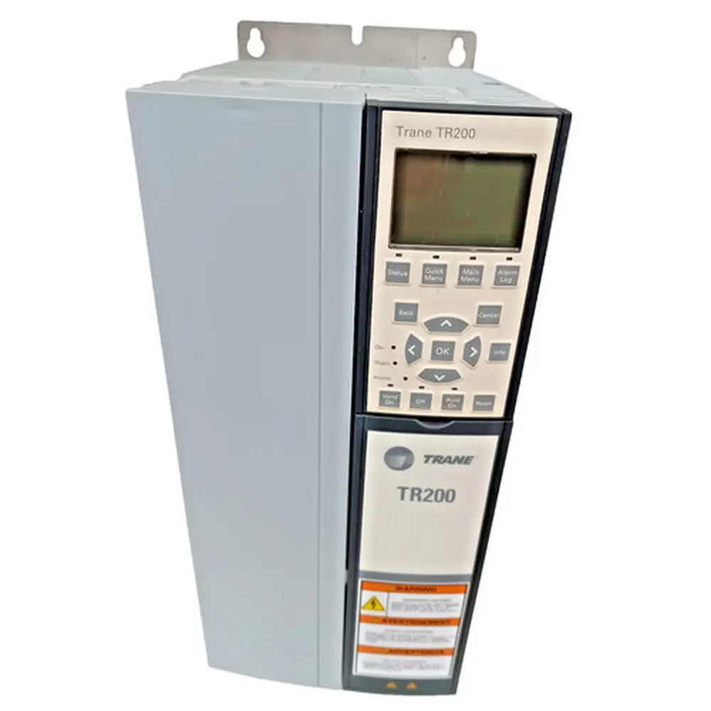
Product Images
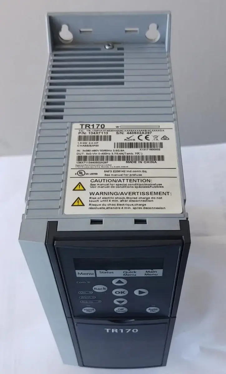


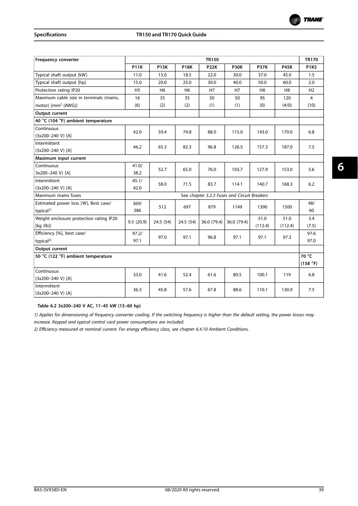
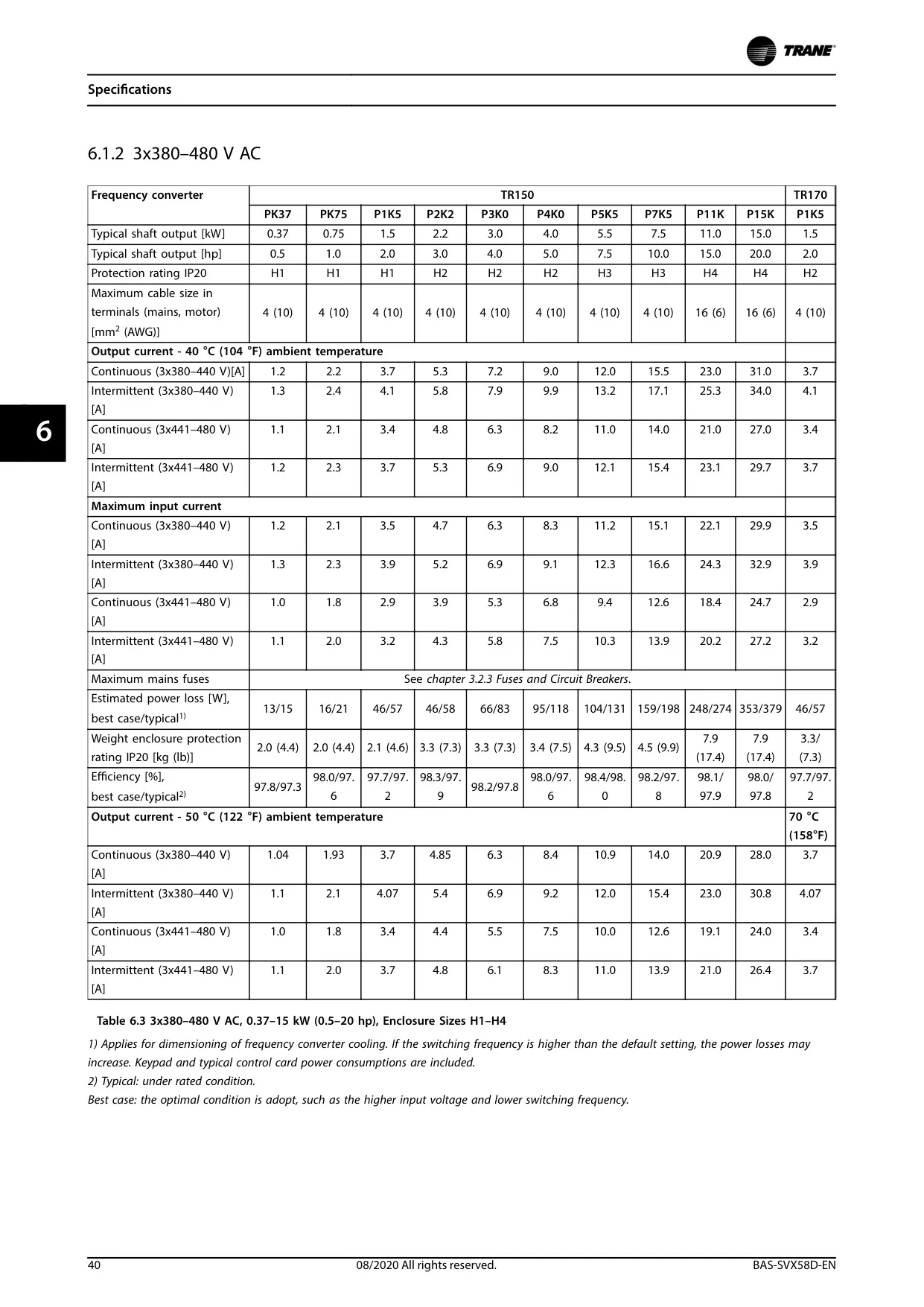
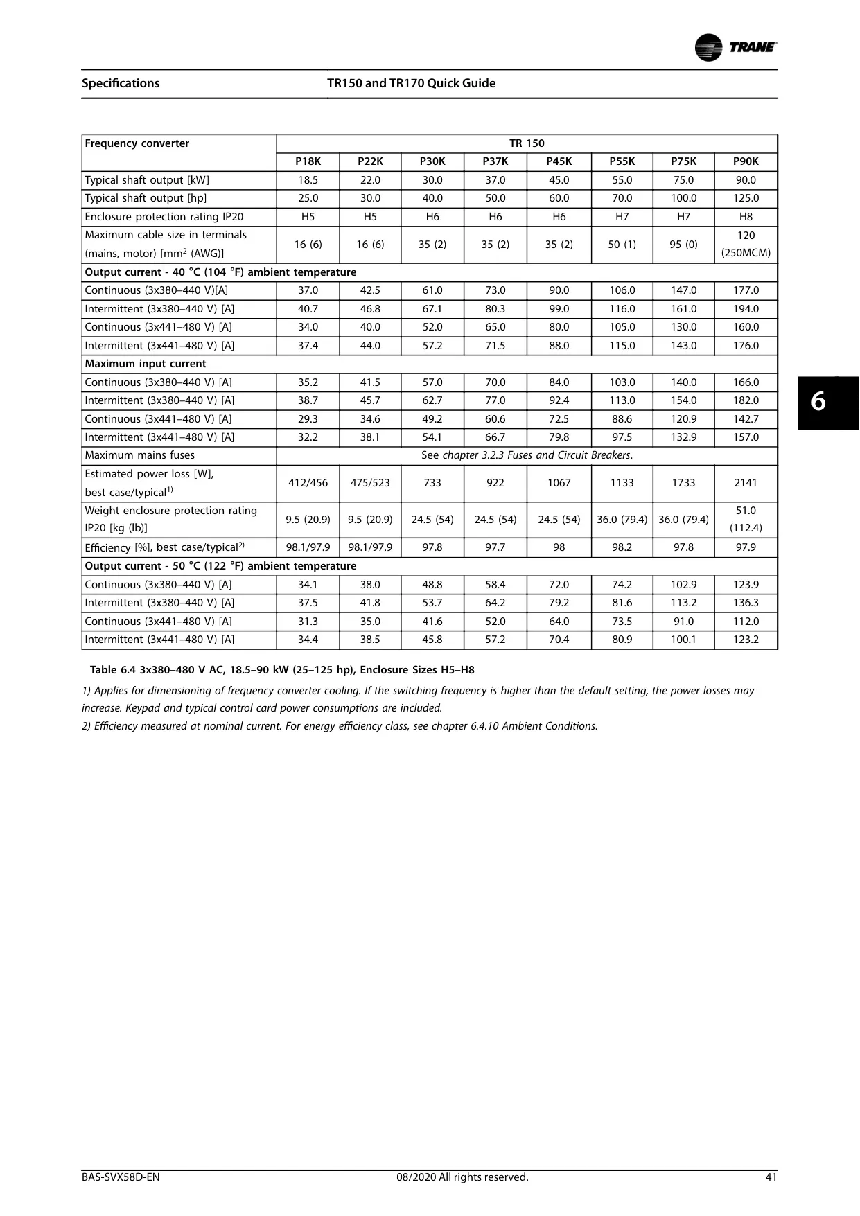
Trane TR170 Variable Frequency Drive Specifications
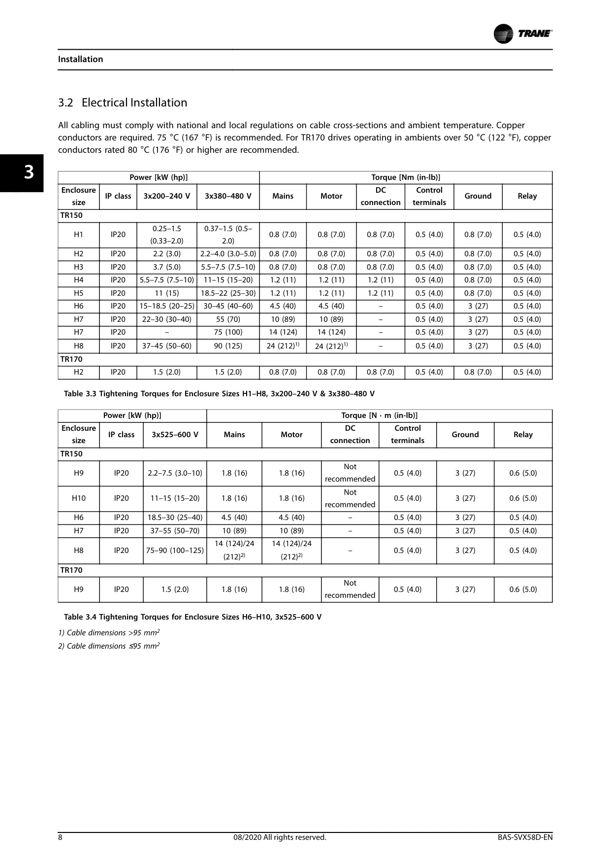
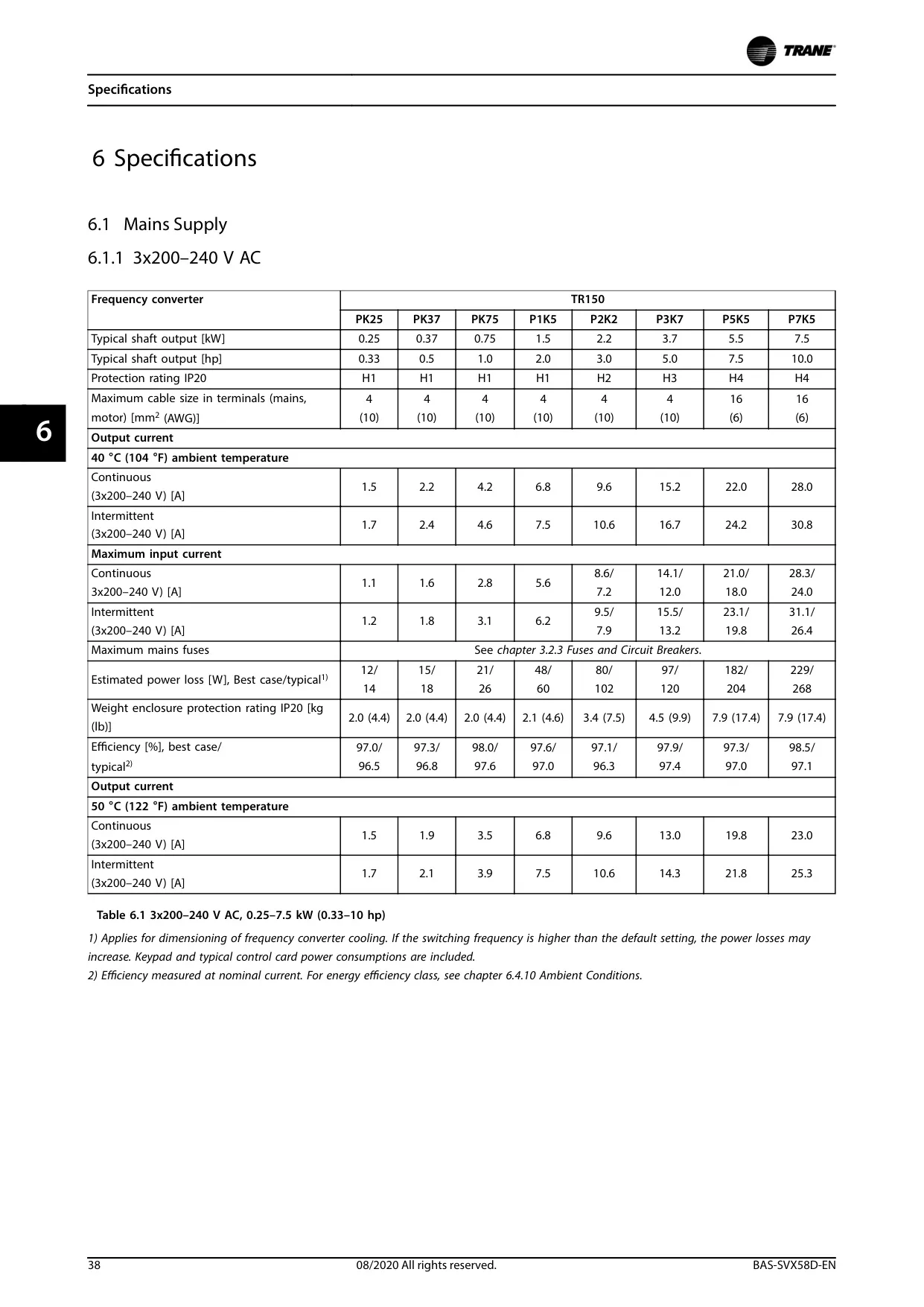
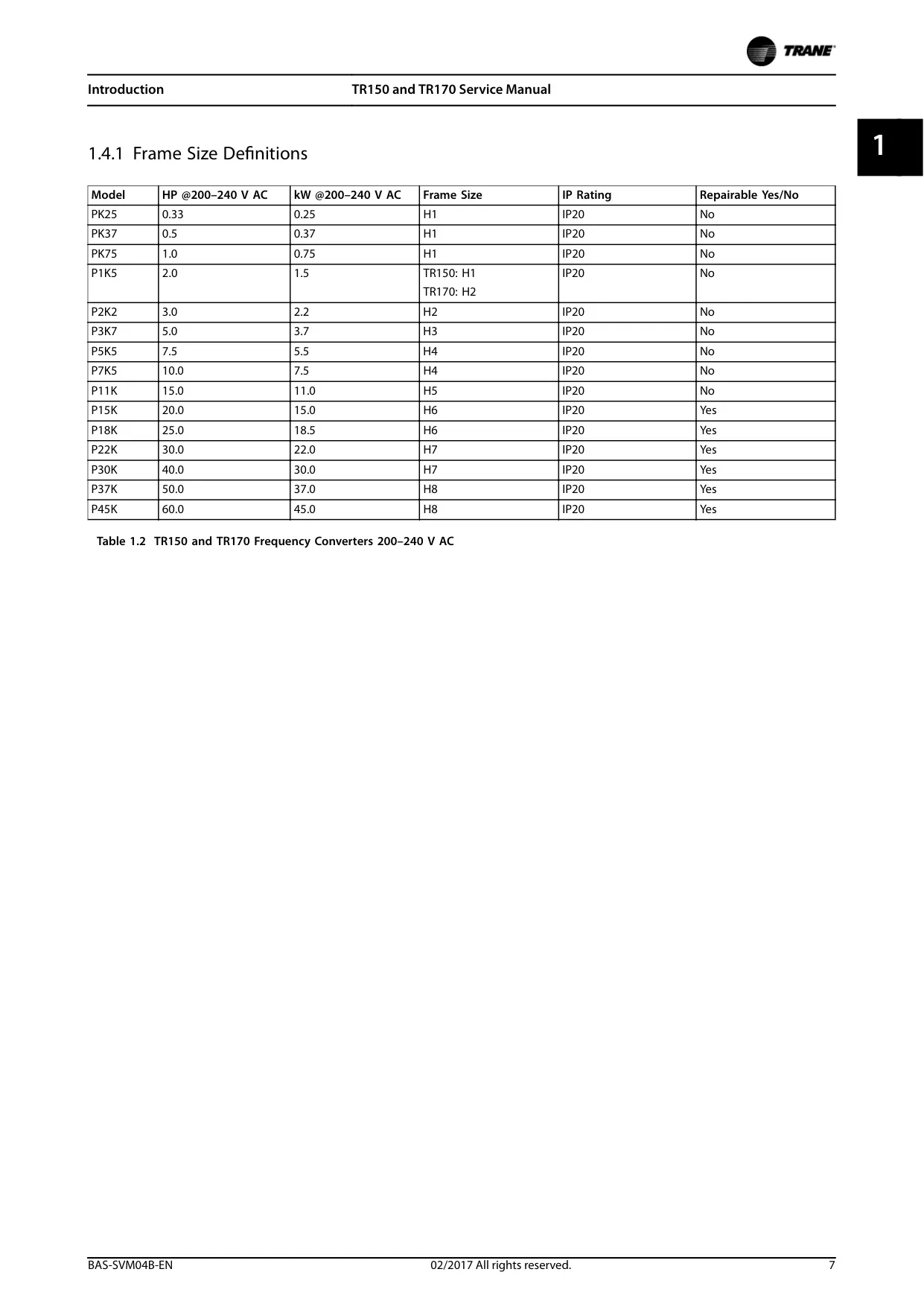
| Voltage Range | Power (HP) | Power (kW) | Frame Size | IP Rating | Repairable |
|---|---|---|---|---|---|
| TR170: 200–240 V AC | |||||
| 200–240 V AC | 2.0 | 1.5 | H2 | IP20 | No |
| 200–240 V AC | 20.0 | 15.0 | H6 | IP20 | Yes |
| 200–240 V AC | 25.0 | 18.5 | H6 | IP20 | Yes |
| 200–240 V AC | 30.0 | 22.0 | H7 | IP20 | Yes |
| 200–240 V AC | 40.0 | 30.0 | H7 | IP20 | Yes |
| 200–240 V AC | 50.0 | 37.0 | H8 | IP20 | Yes |
| 200–240 V AC | 60.0 | 45.0 | H8 | IP20 | Yes |
| TR170: 380–480 V AC | |||||
| 380–480 V AC | 2.0 | 1.5 | H2 | IP20 | No |
| 380–480 V AC | 30.0 | 22.0 | I6 | IP54 | Yes |
| 380–480 V AC | 40.0 | 30.0 | I6 | IP54 | Yes |
| 380–480 V AC | 50.0 | 37.0 | I6 | IP54 | Yes |
| 380–480 V AC | 60.0 | 45.0 | I7 | IP54 | Yes |
| 380–480 V AC | 70.0 | 55.0 | I7 | IP54 | Yes |
| 380–480 V AC | 100.0 | 75.0 | I8 | IP54 | Yes |
| 380–480 V AC | 125.0 | 90.0 | I8 | IP54 | Yes |
| TR170: 525–600 V AC | |||||
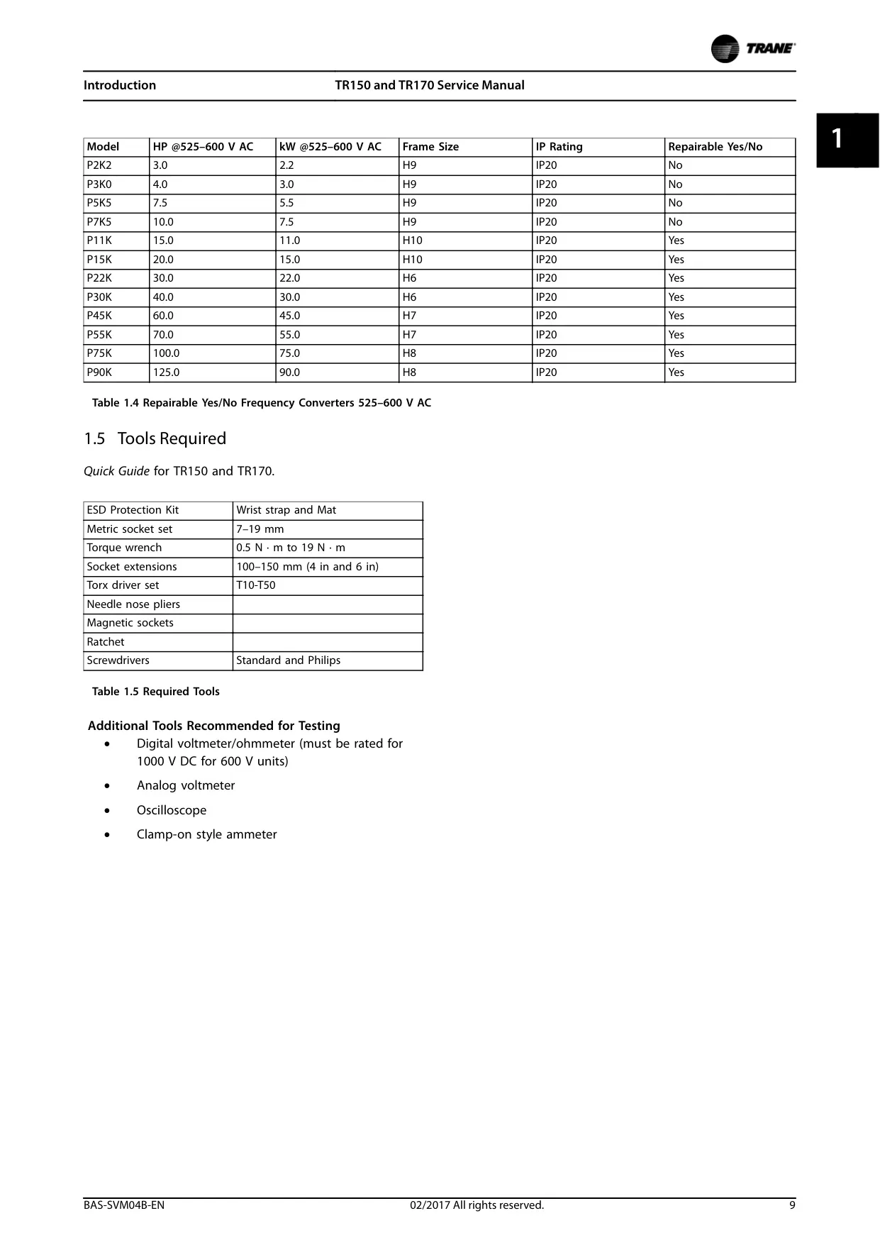
| 525–600 V AC | 15.0 | 11.0 | H10 | IP20 | Yes |
| 525–600 V AC | 20.0 | 15.0 | H10 | IP20 | Yes |
| 525–600 V AC | 30.0 | 22.0 | H6 | IP20 | Yes |
| 525–600 V AC | 40.0 | 30.0 | H6 | IP20 | Yes |
| 525–600 V AC | 60.0 | 45.0 | H7 | IP20 | Yes |
| 525–600 V AC | 70.0 | 55.0 | H7 | IP20 | Yes |
| 525–600 V AC | 100.0 | 75.0 | H8 | IP20 | Yes |
| 525–600 V AC | 125.0 | 90.0 | H8 | IP20 | Yes |
| DC Voltage Levels (Nominal) | |||||
| 200–240 V AC Input | Inrush enabled: 202 V | Overvoltage: 410 V | |||
| 380–480 V AC Input | Inrush enabled: 314-372 V | Overvoltage: 800 V | |||
| 525–600 V AC Input | Inrush enabled: 532 V | Overvoltage: 976 V | |||
Trane TR170 VFD Details
The Trane TR170 VFD is a sophisticated frequency converter specifically engineered for Heating, Ventilation, and Air-Conditioning (HVAC) applications. It operates primarily in variable torque mode, making it ideally suited for controlling fans and pumps with optimal efficiency and reduced energy consumption. This focus allows for tailored performance in dynamic building environments, ensuring precise control over air and fluid movement.
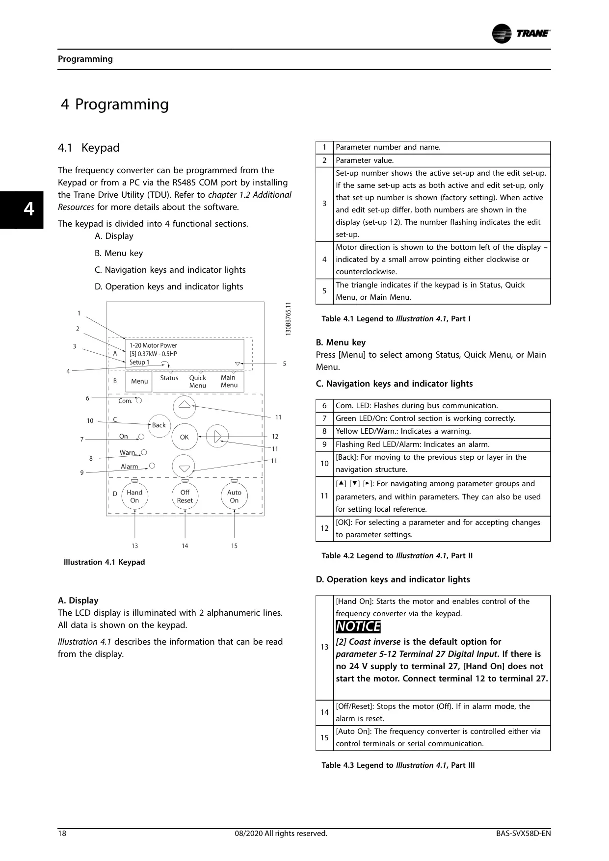
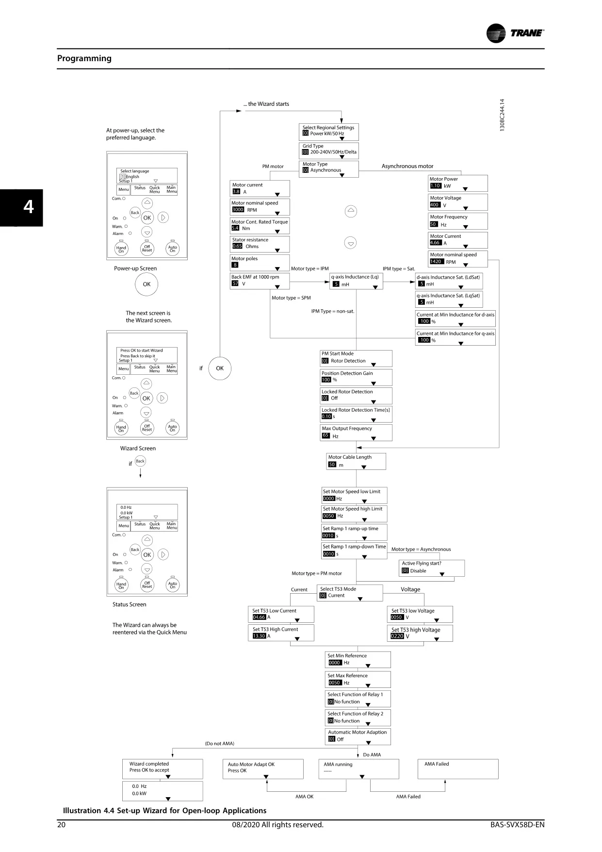
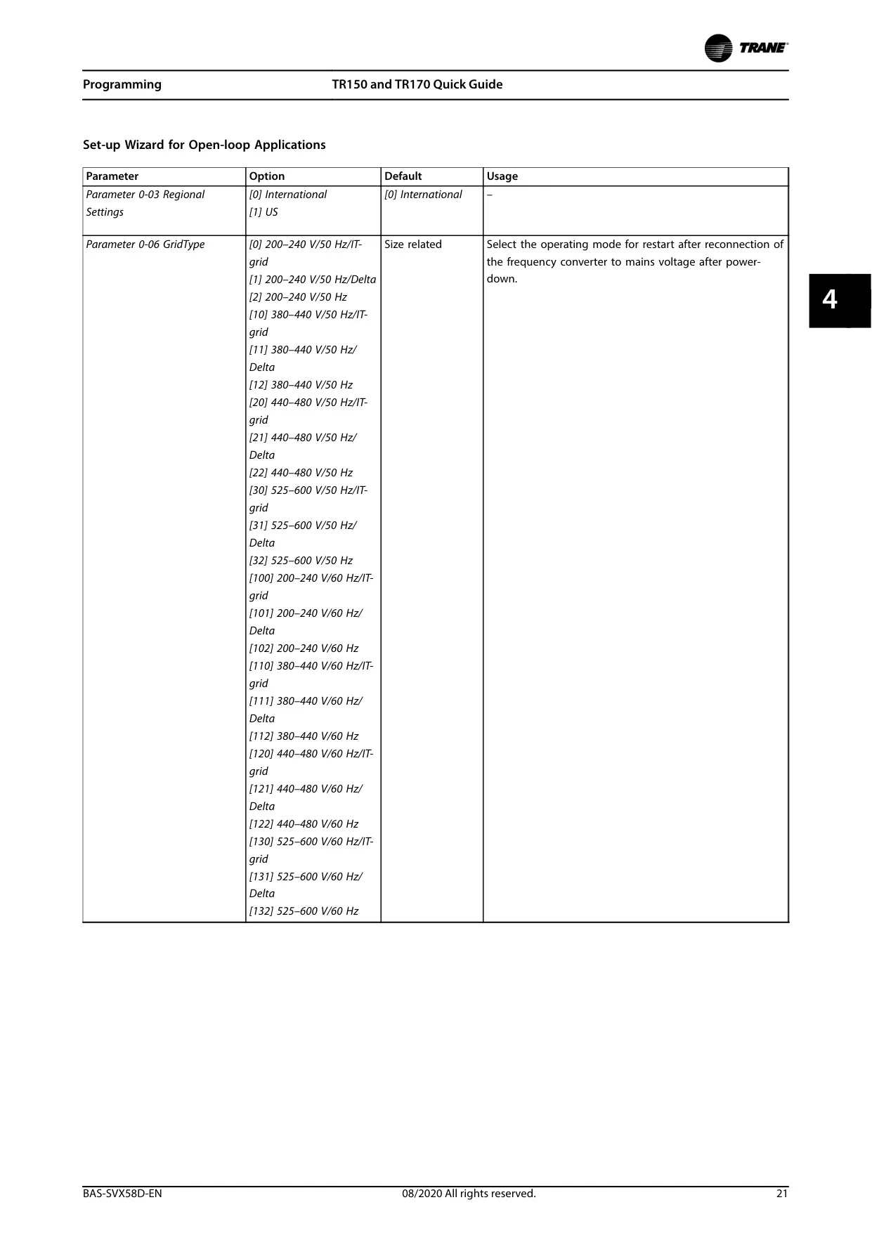
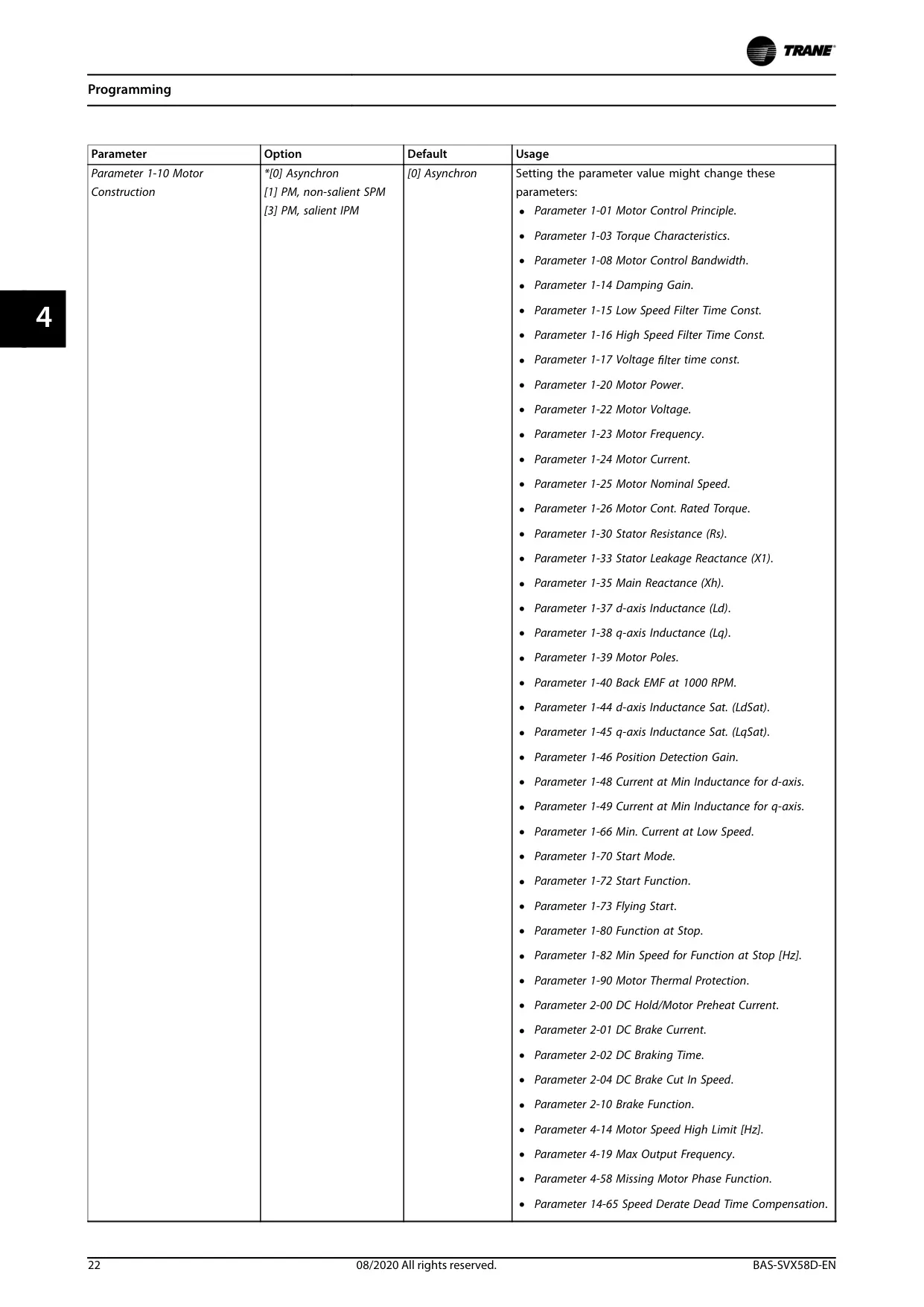
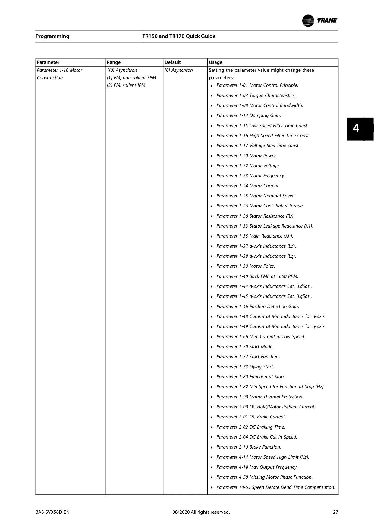
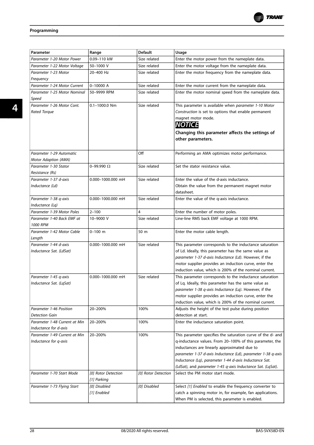
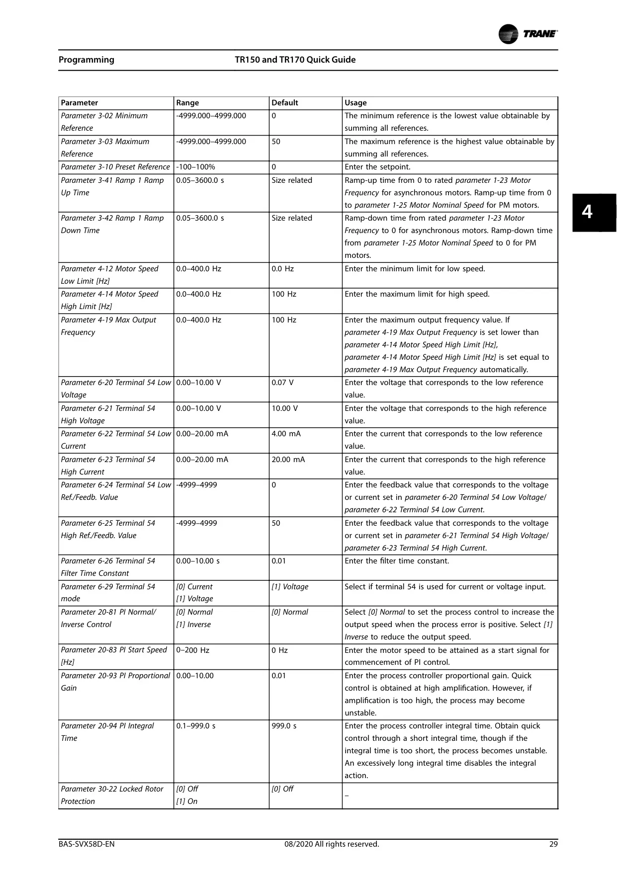
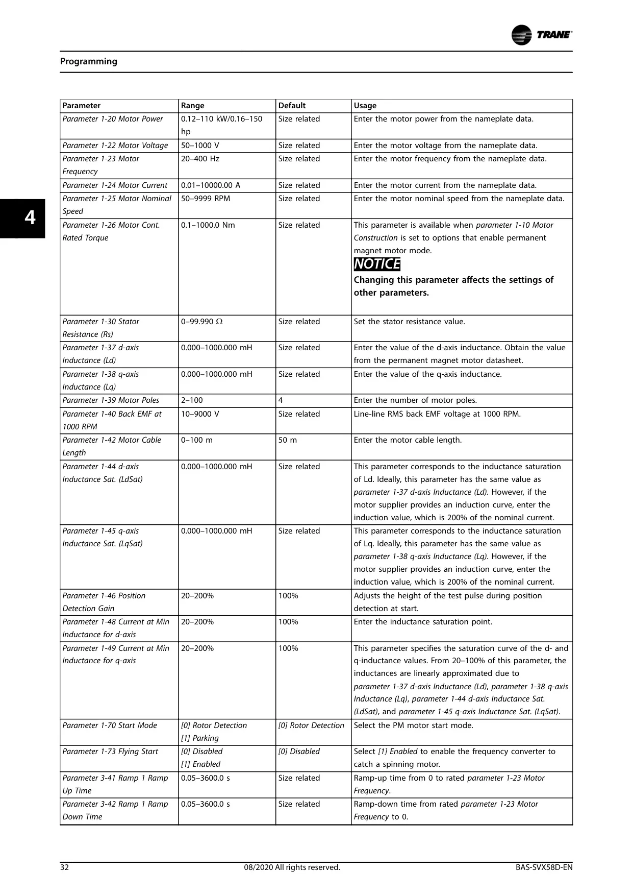
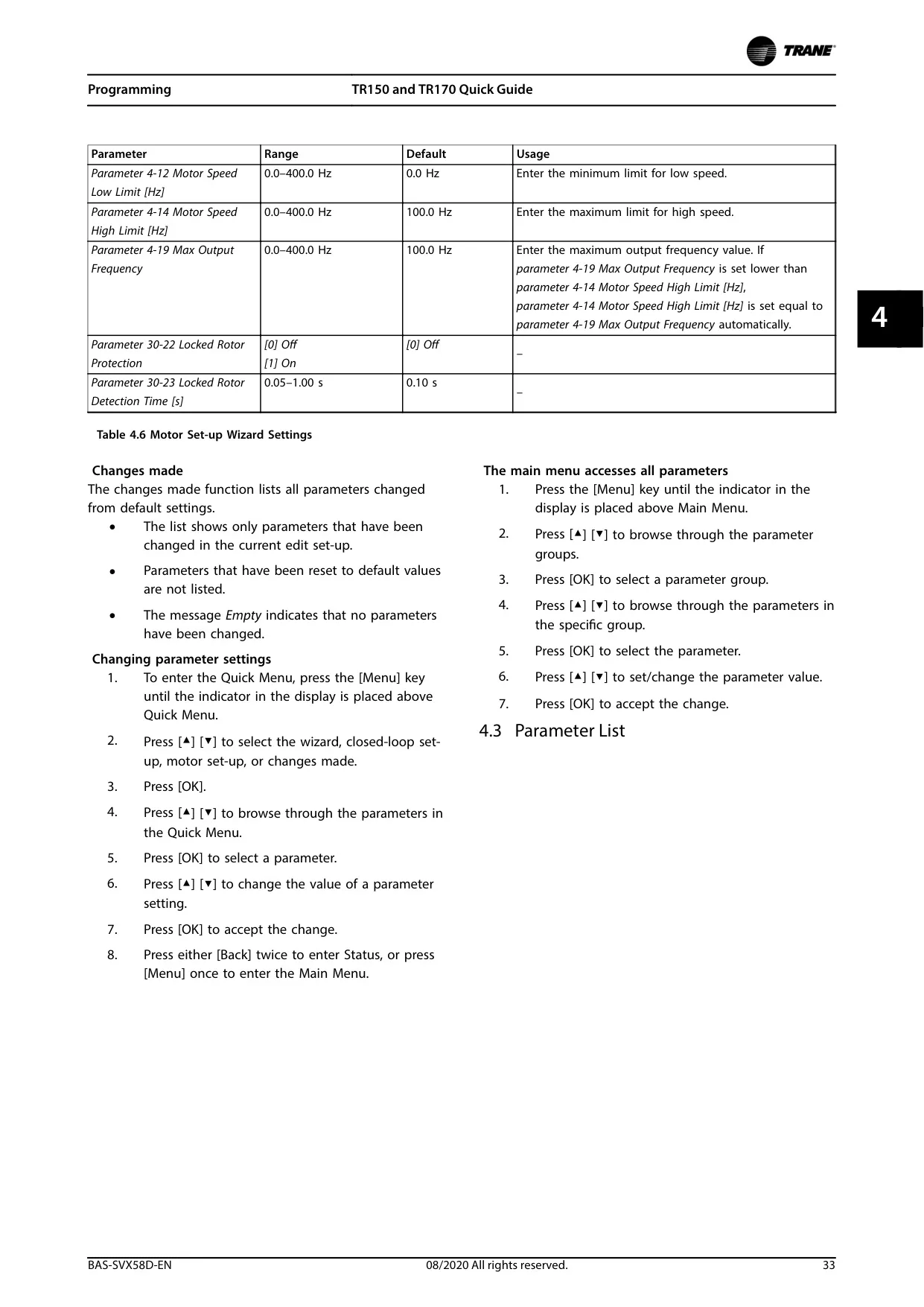
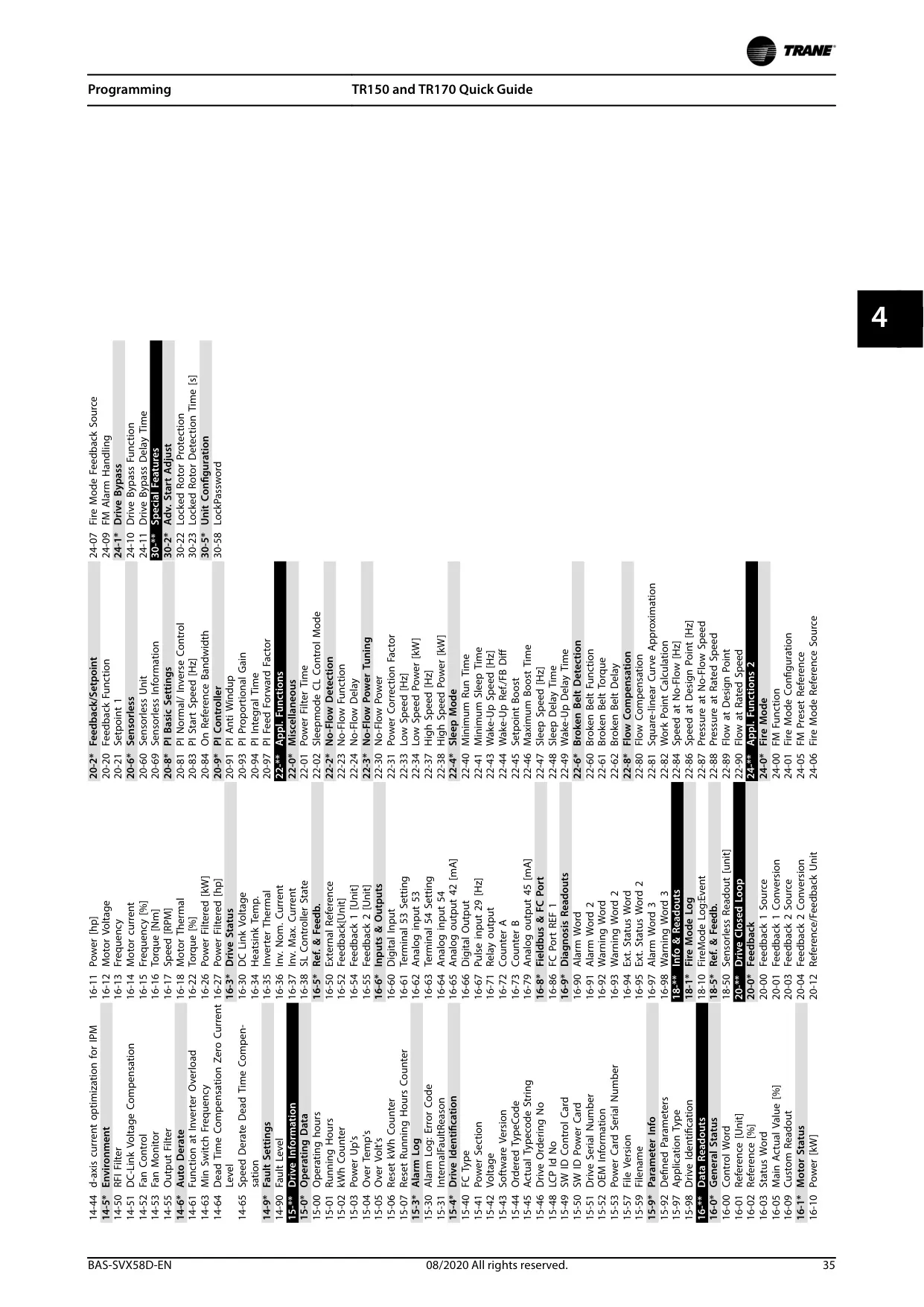
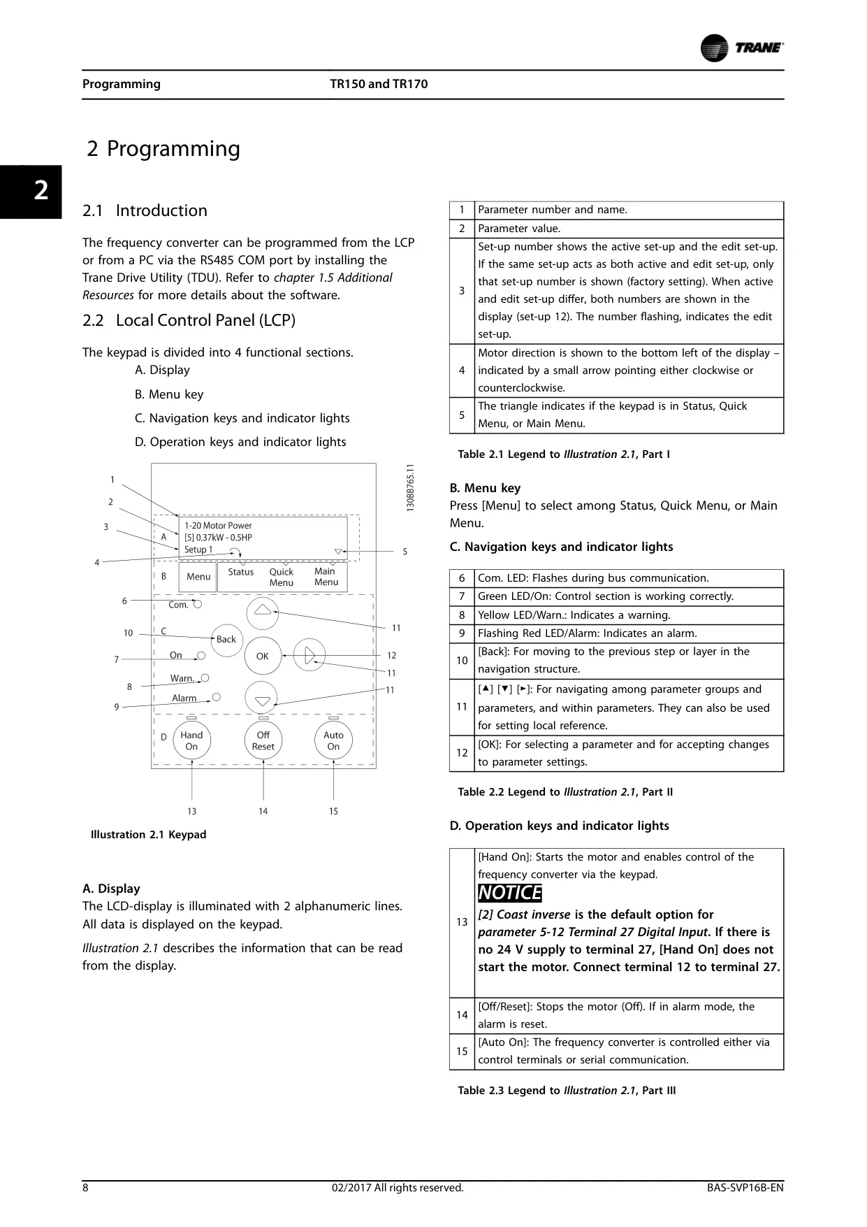
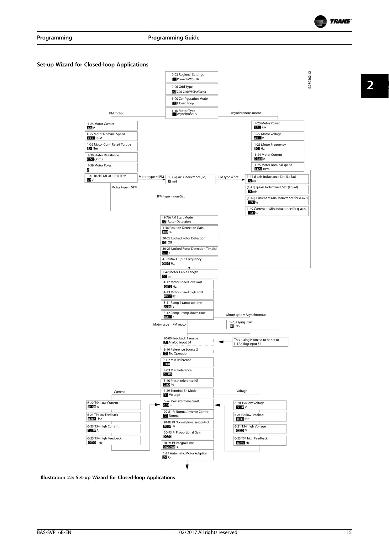
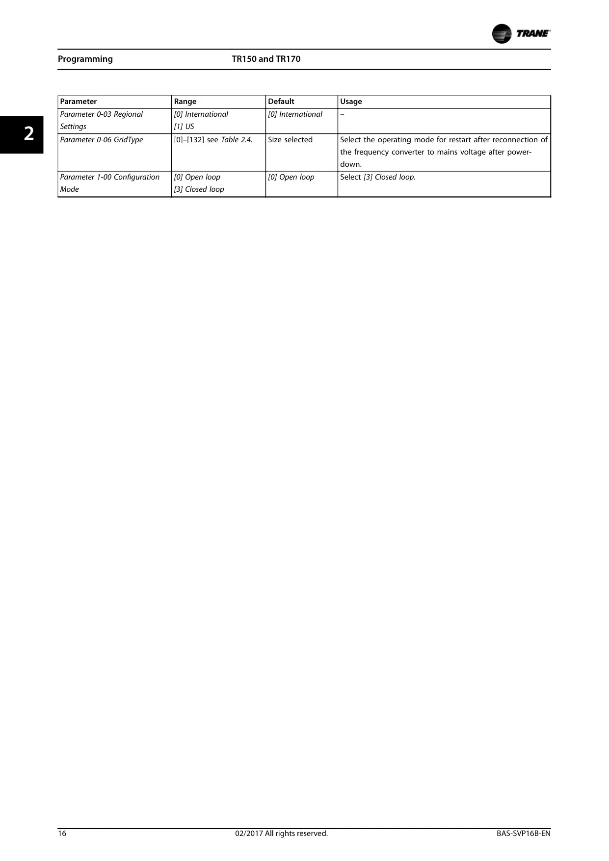
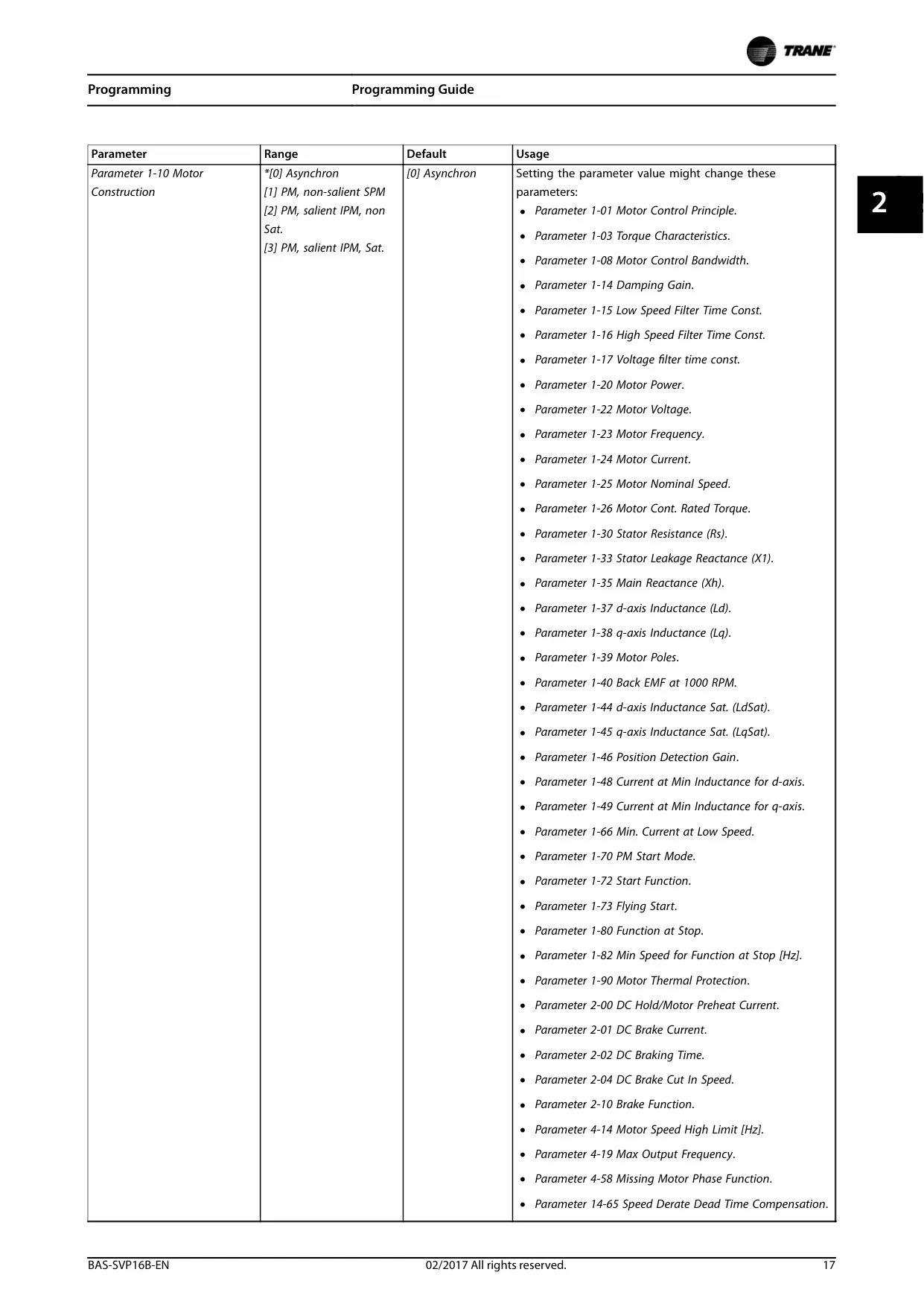
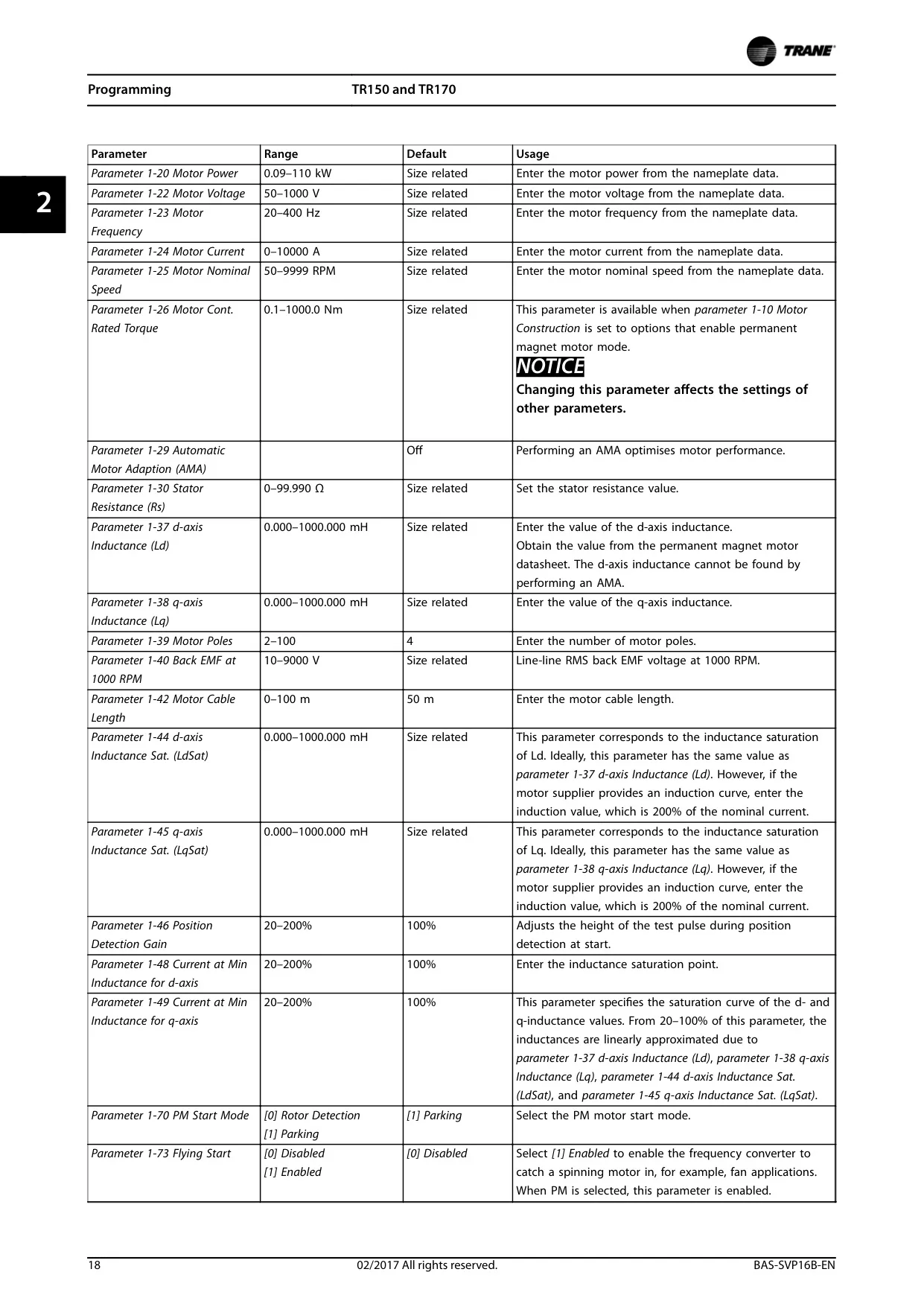
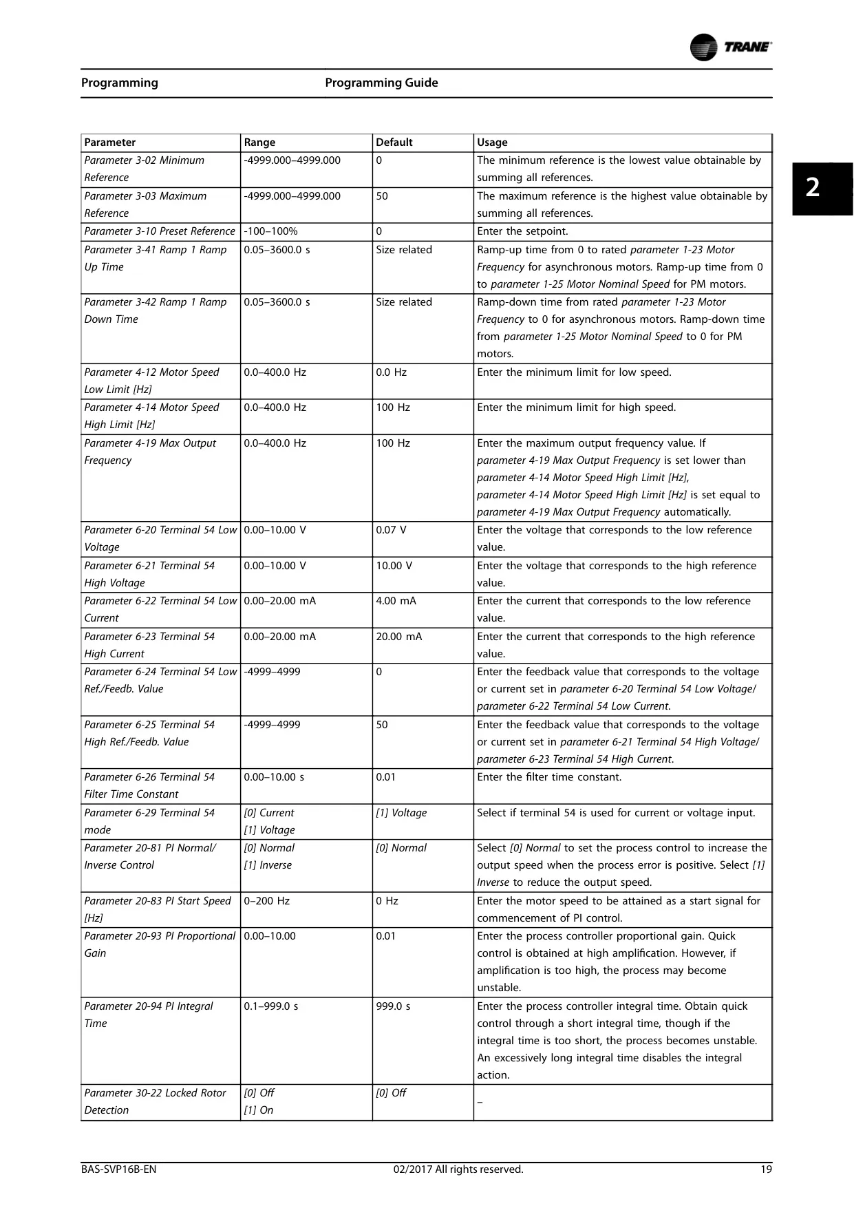
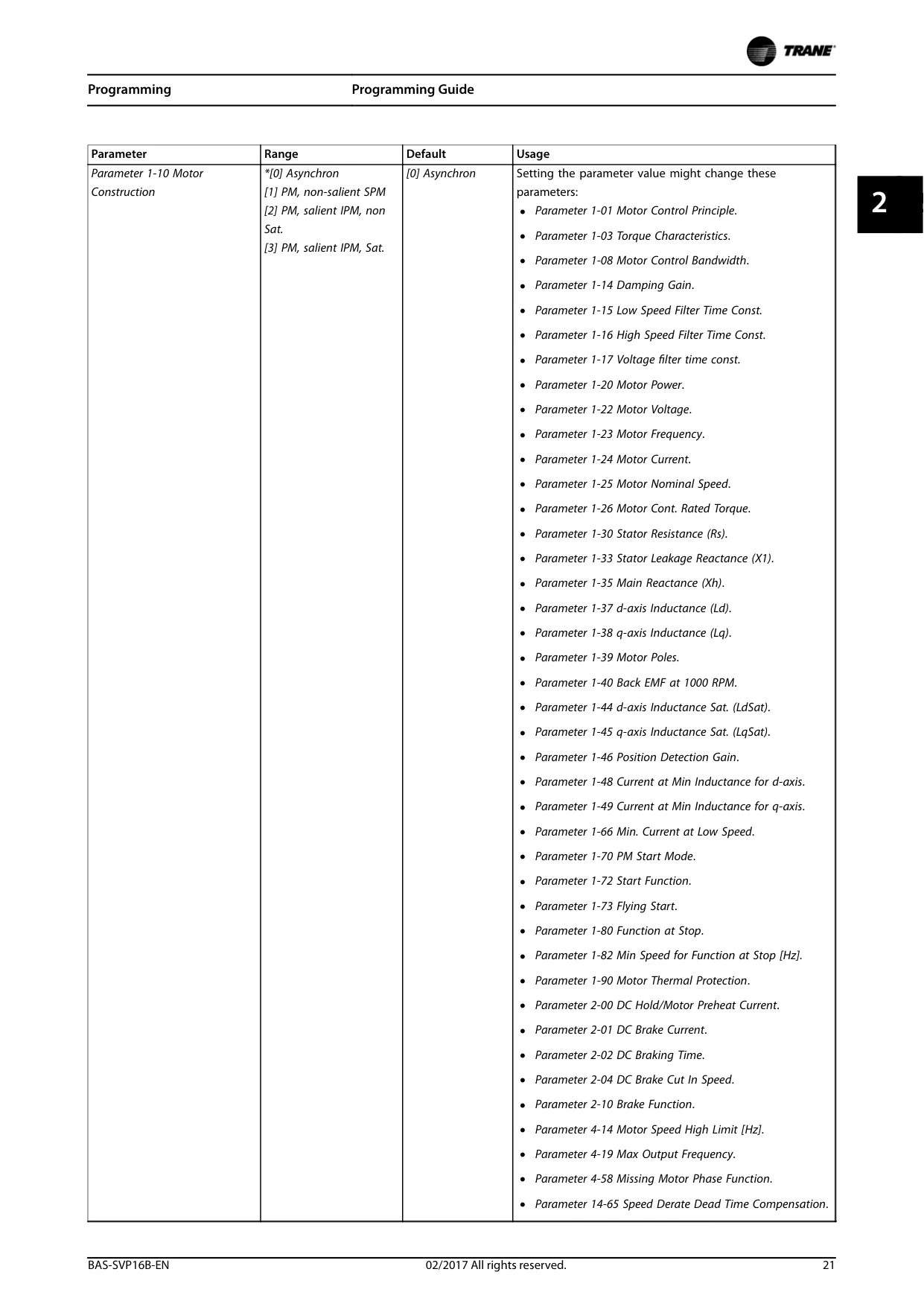
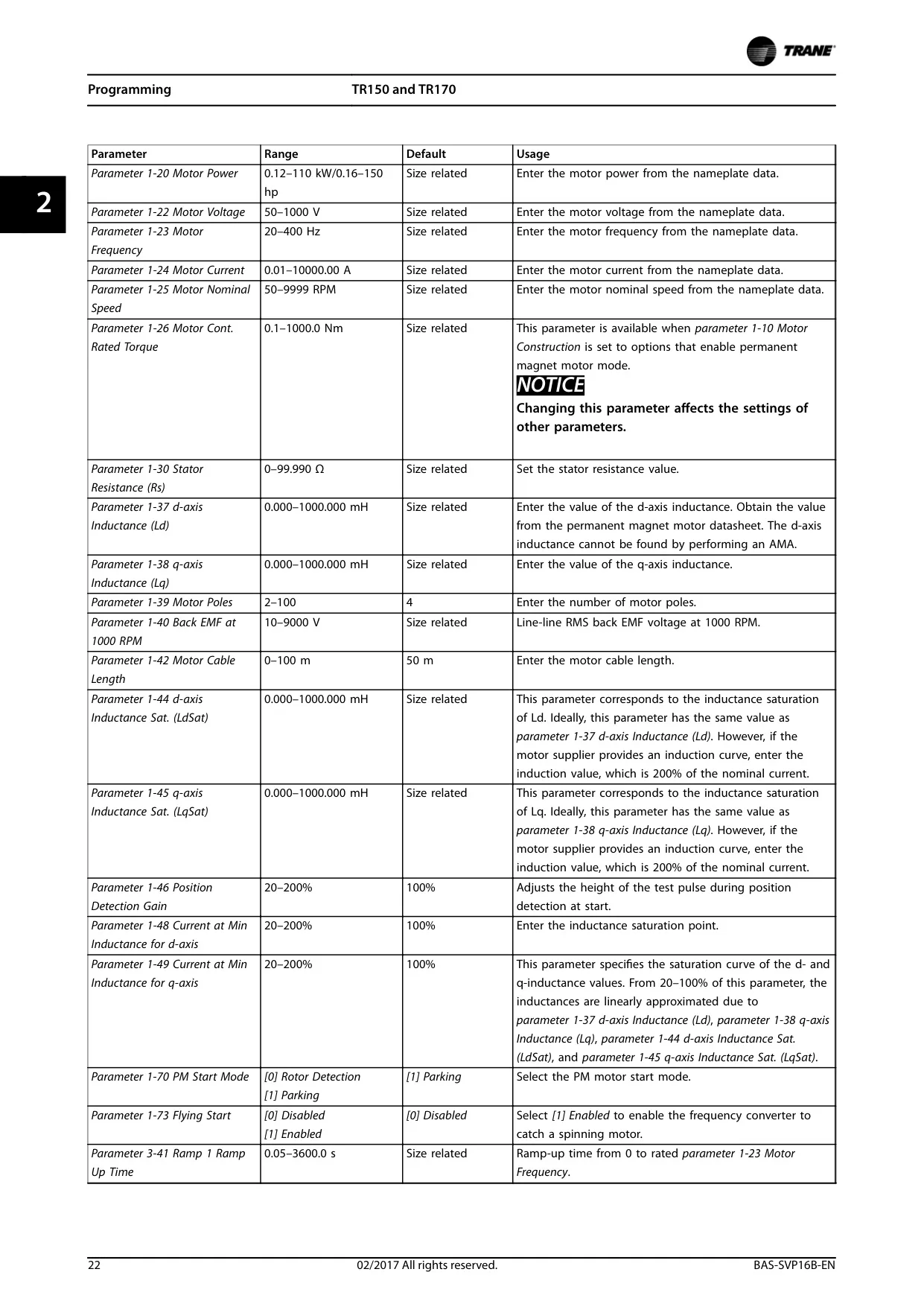
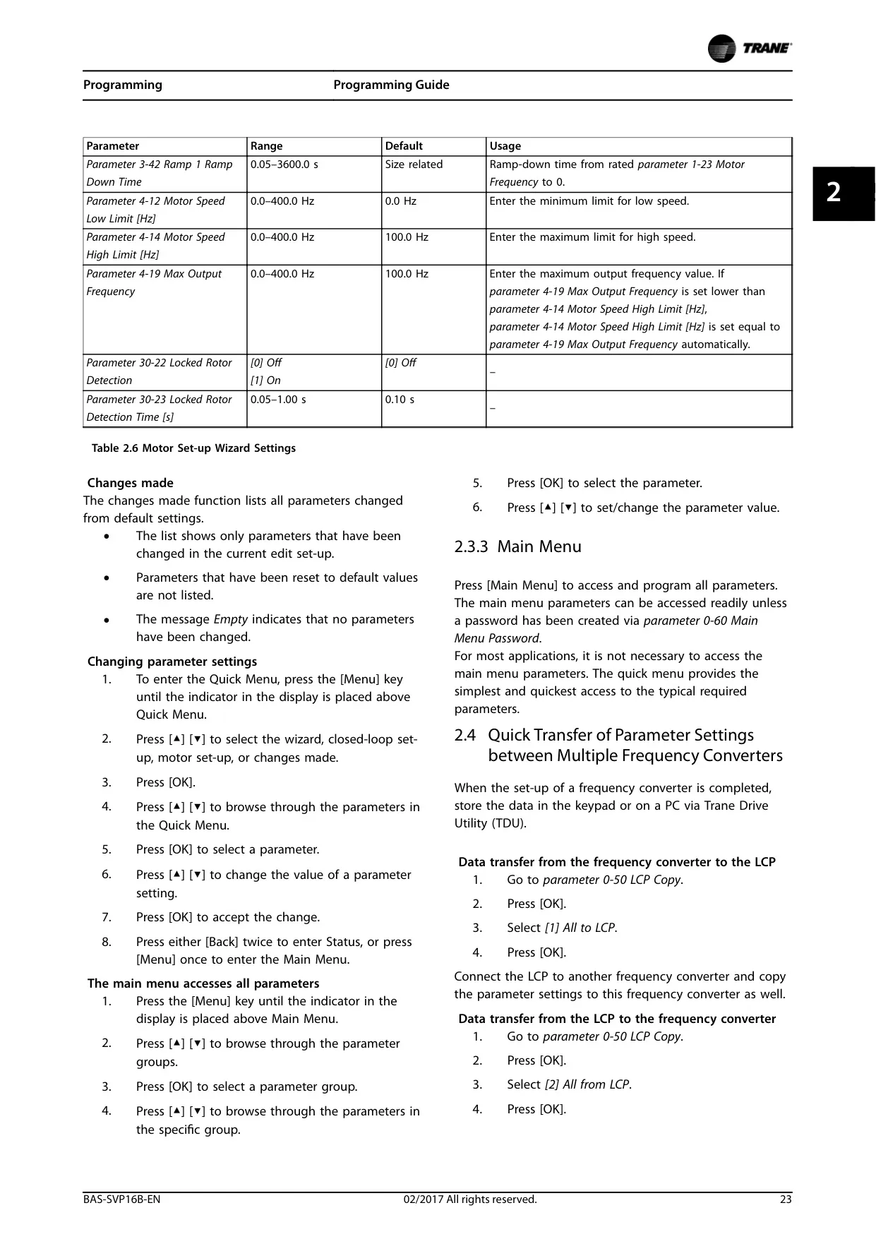
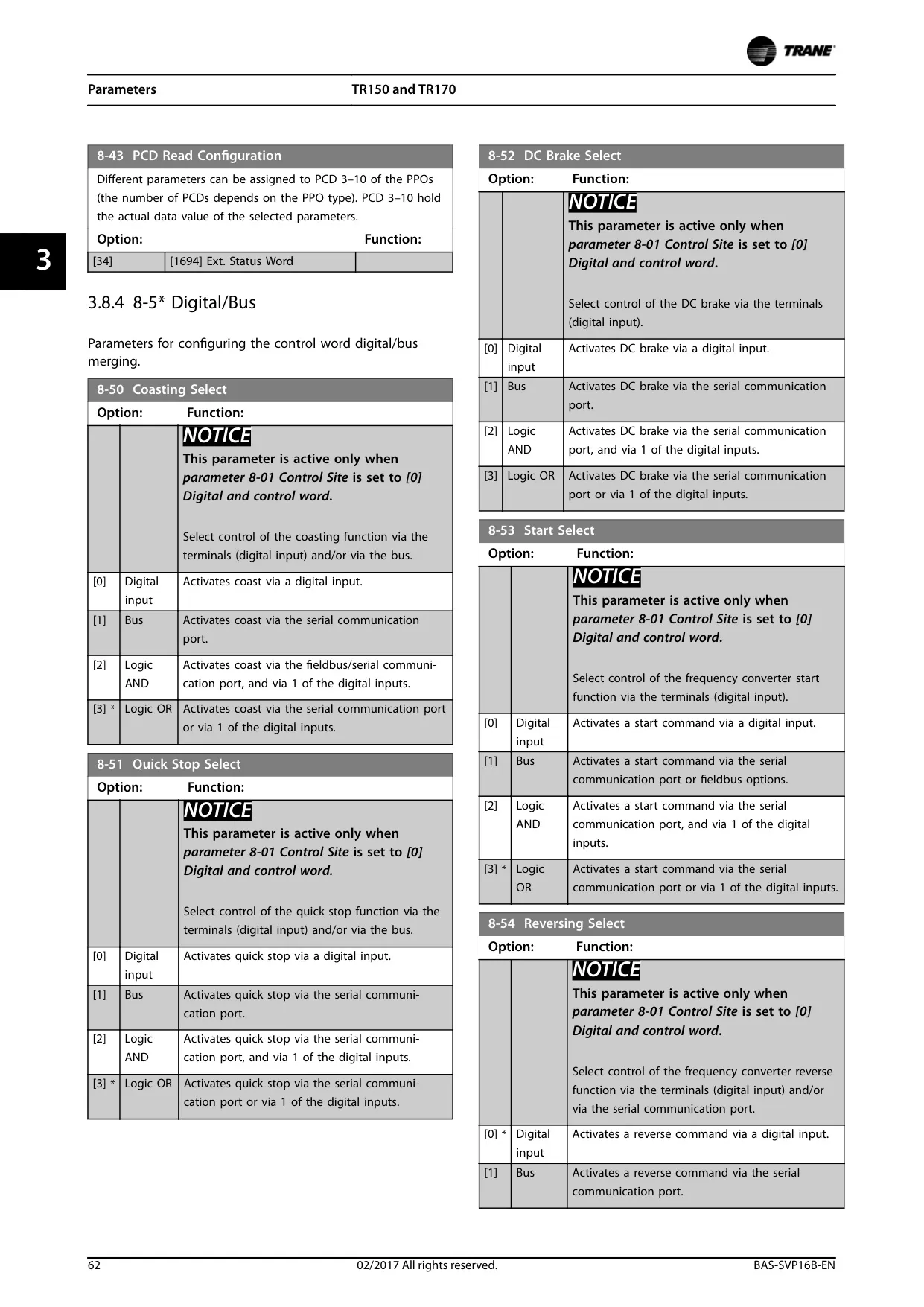
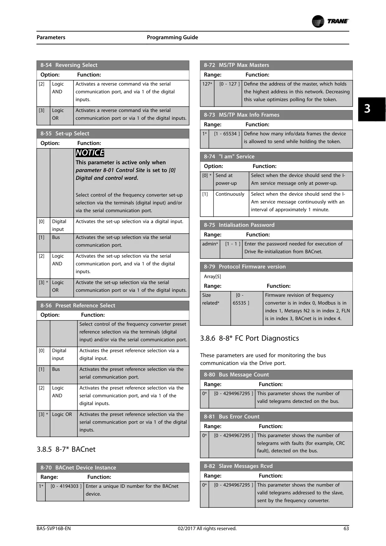
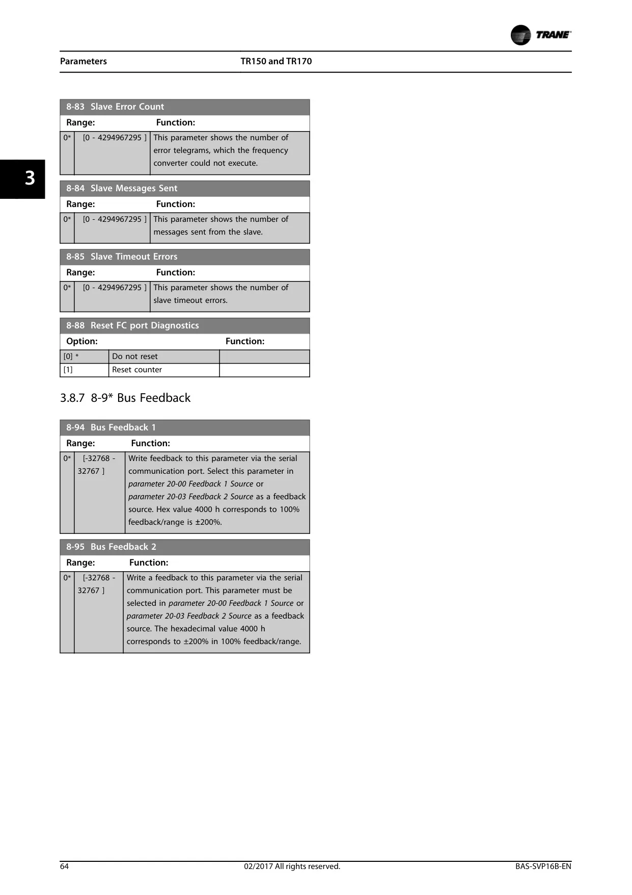
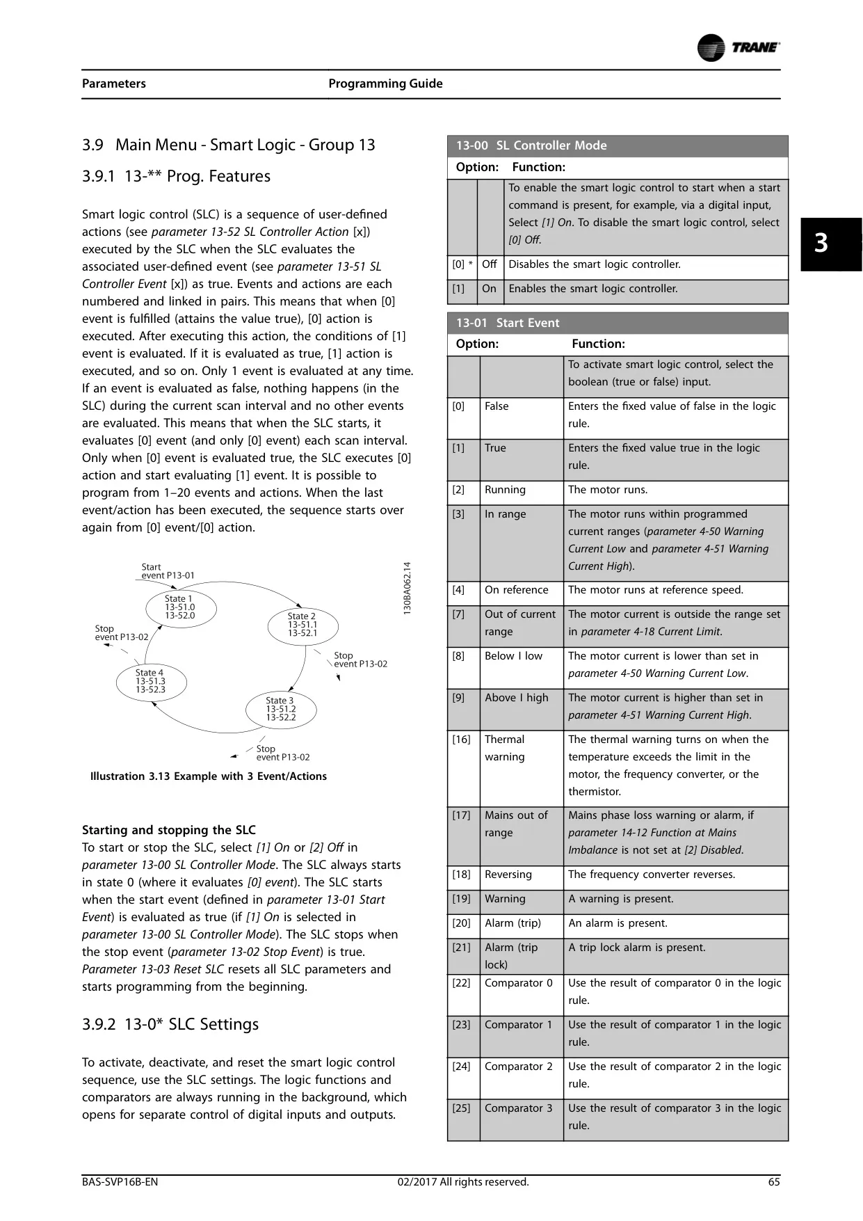
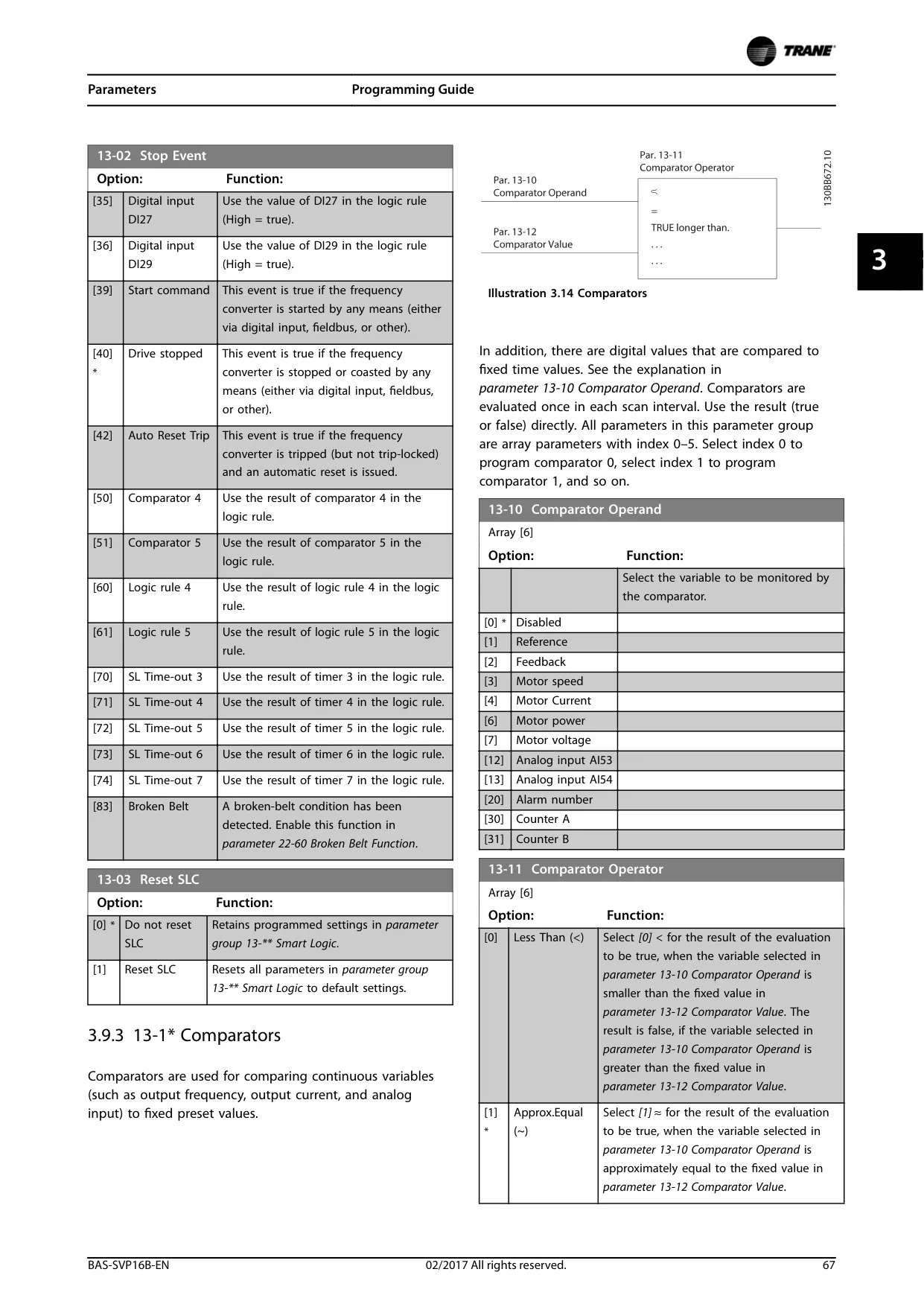
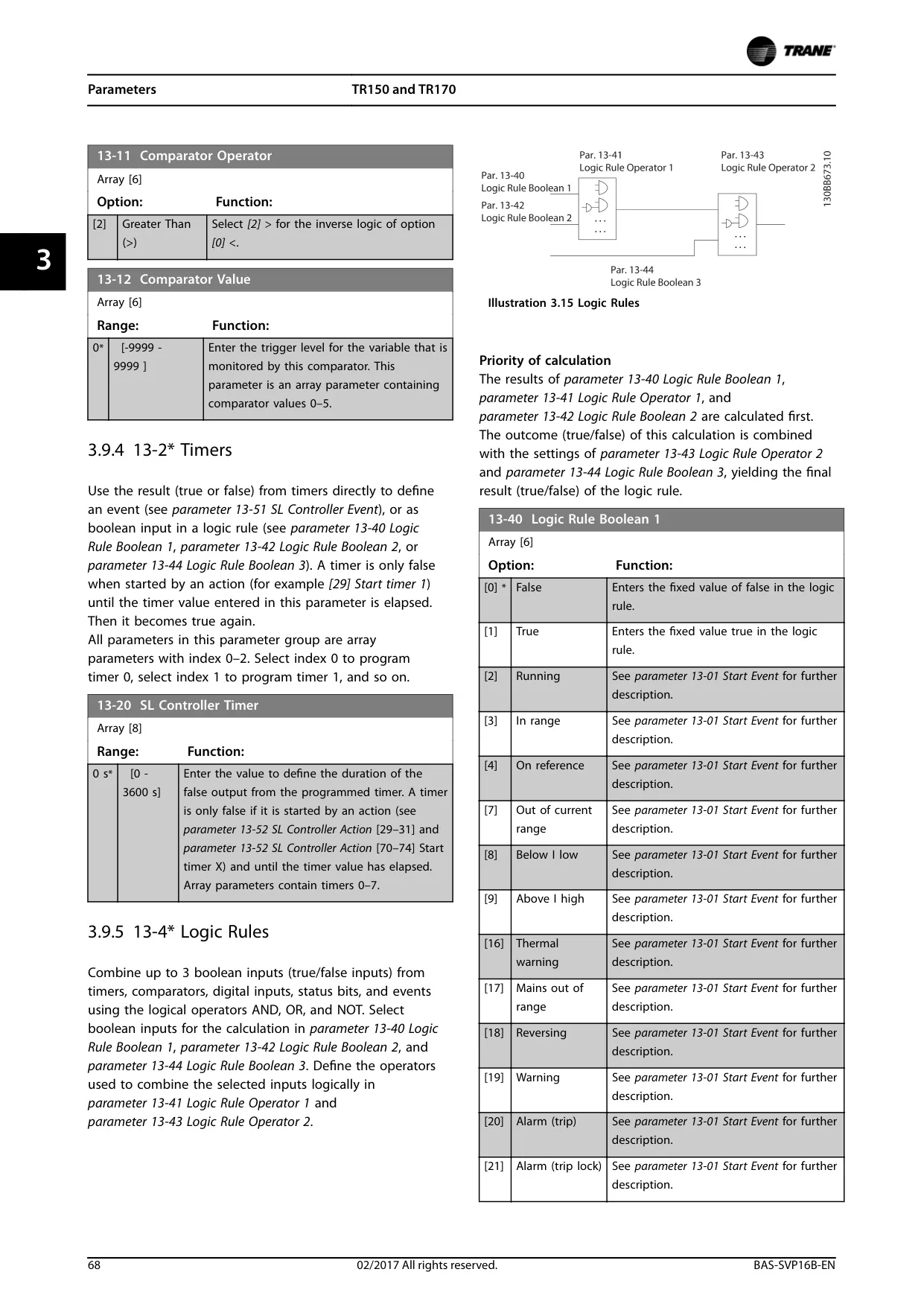
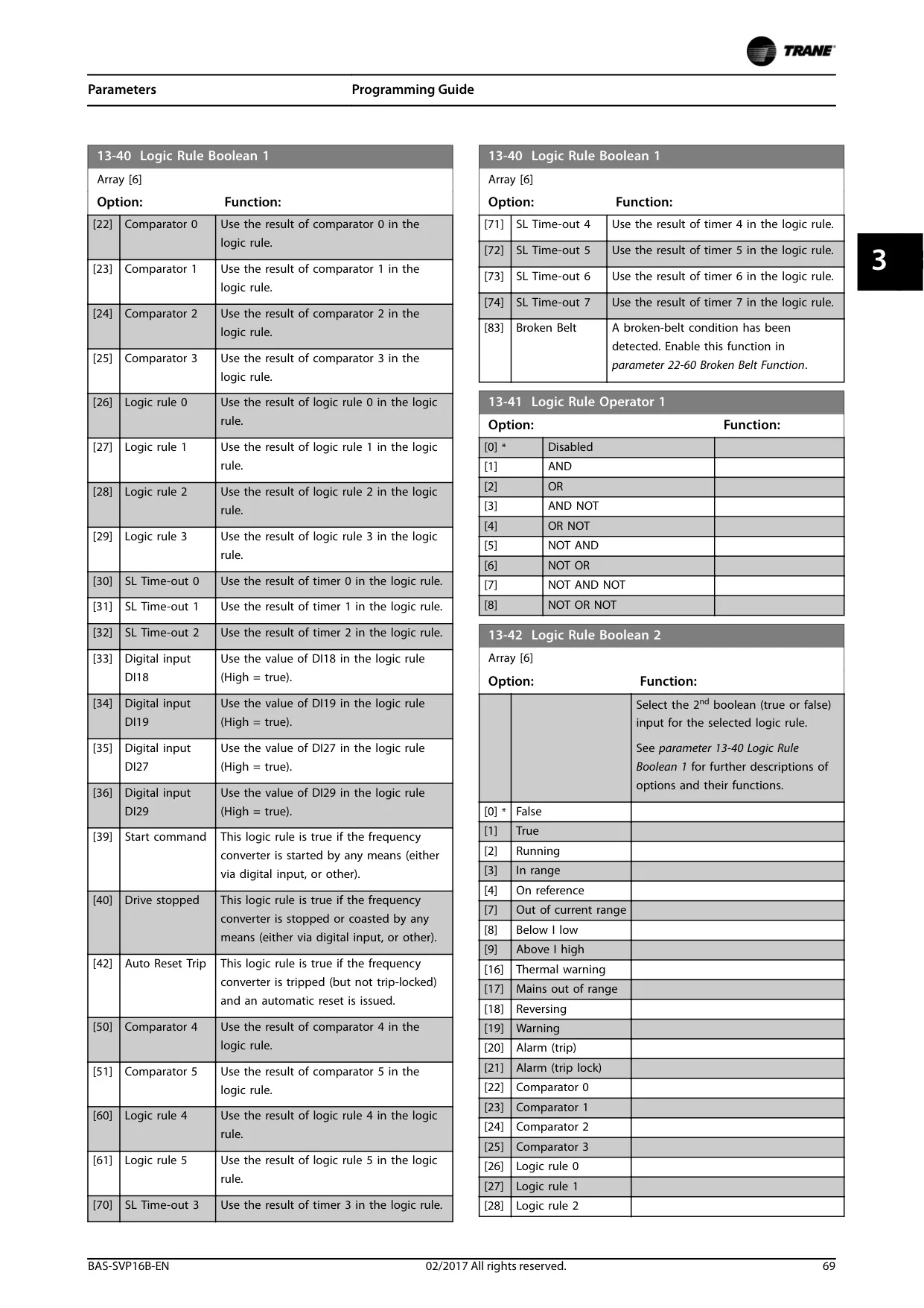
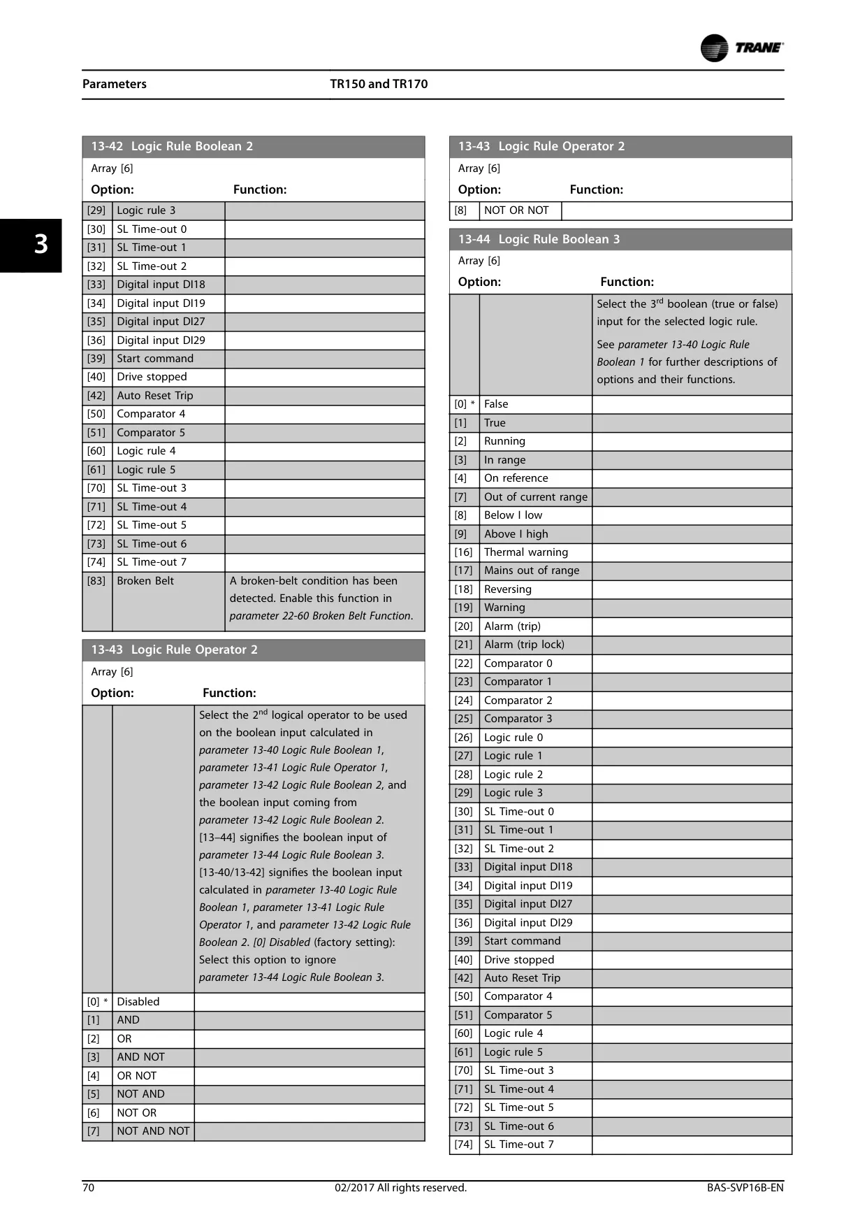
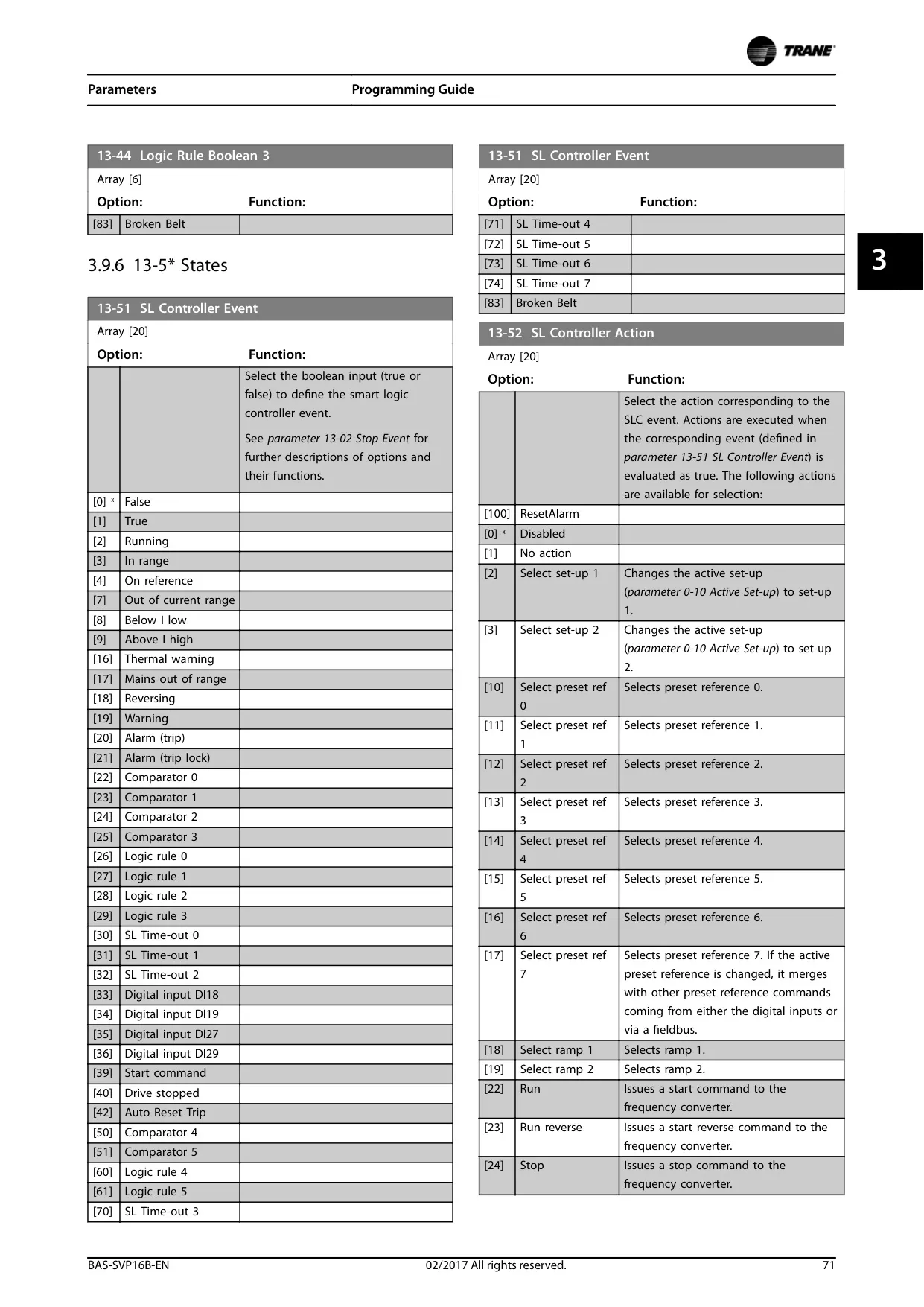
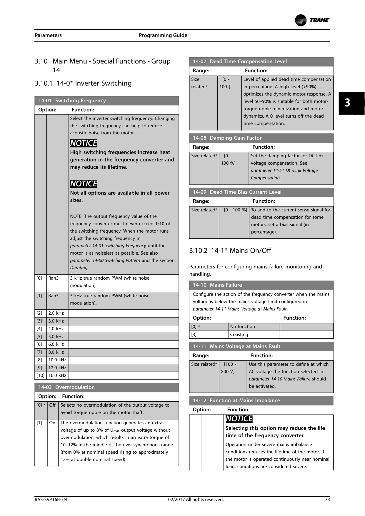
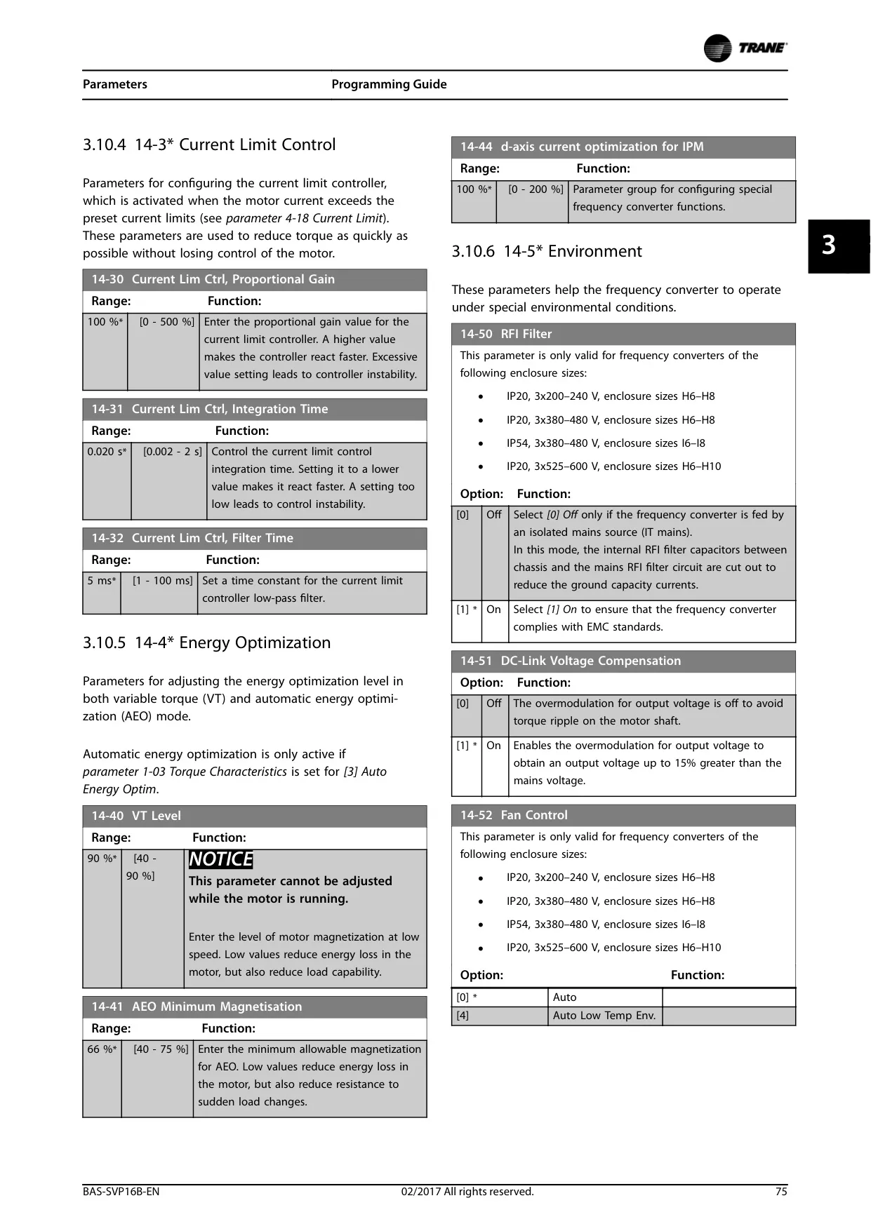
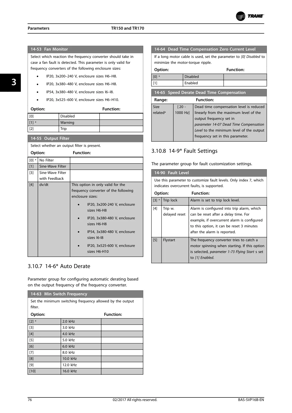
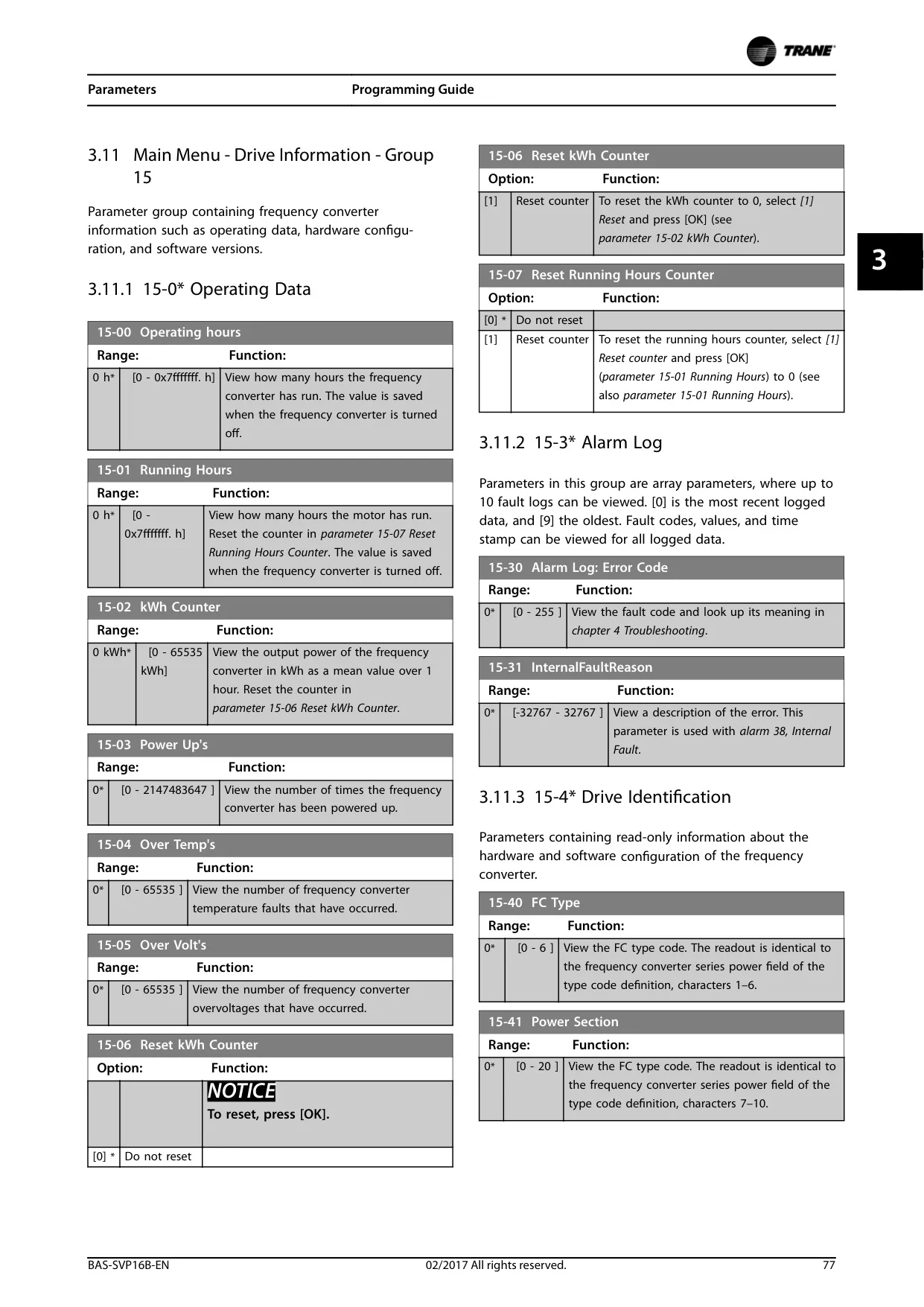
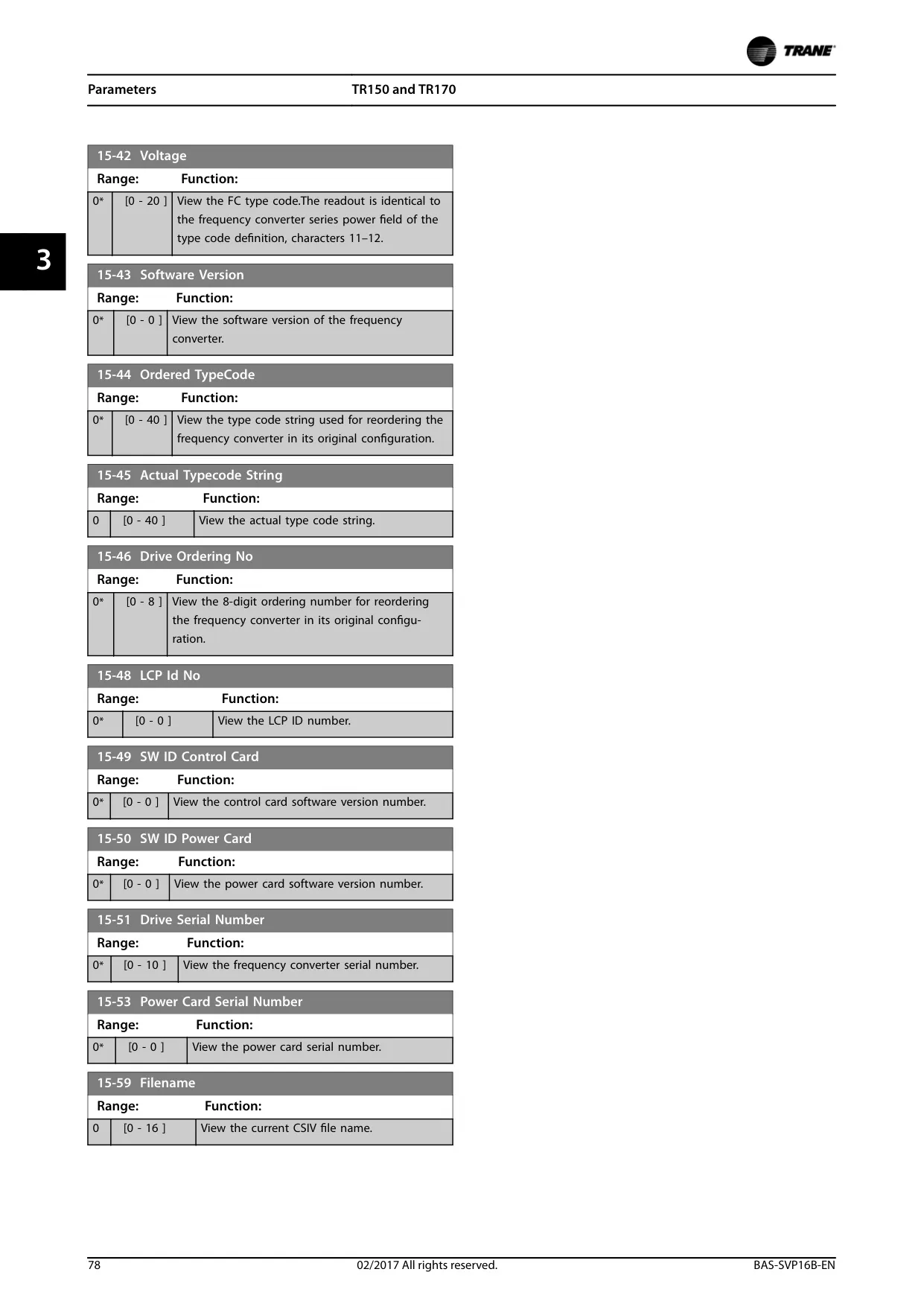
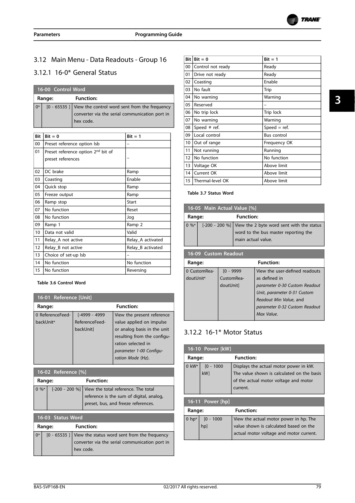
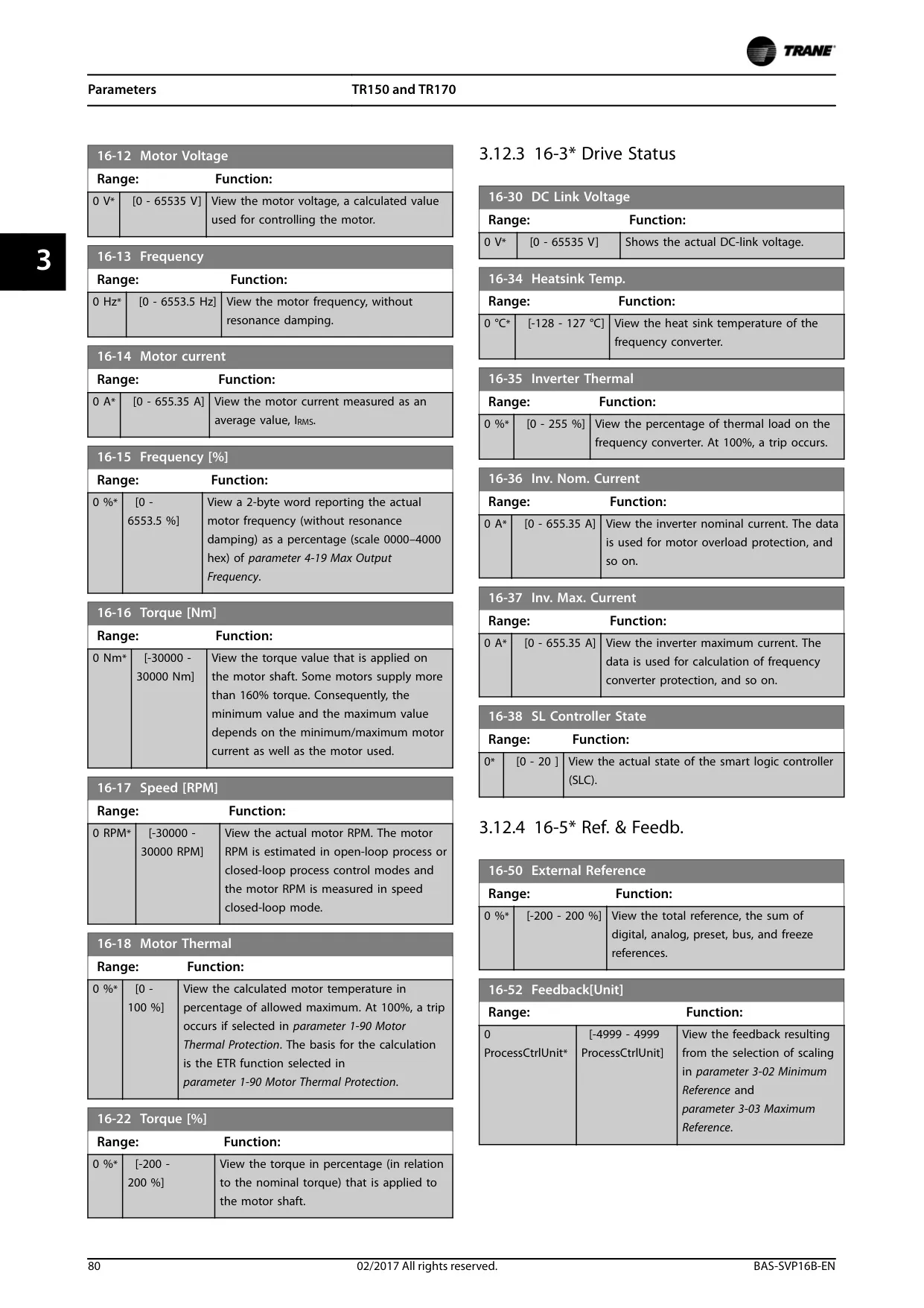
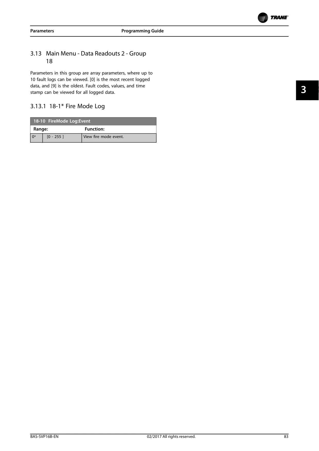
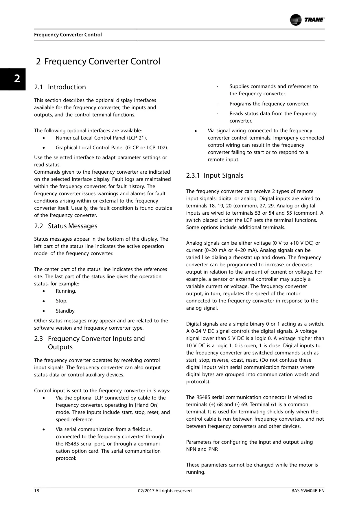
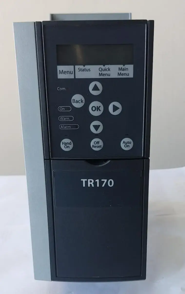
User interaction with the TR170 VFD is facilitated through several optional interfaces, including the Numerical Local Control Panel (LCP 21) and the Graphical Local Control Panel (GLCP or LCP 102). These panels enable technicians to easily adapt parameter settings, monitor operational status, and review historical fault logs, offering both visual feedback and hands-on control for commissioning and maintenance tasks.
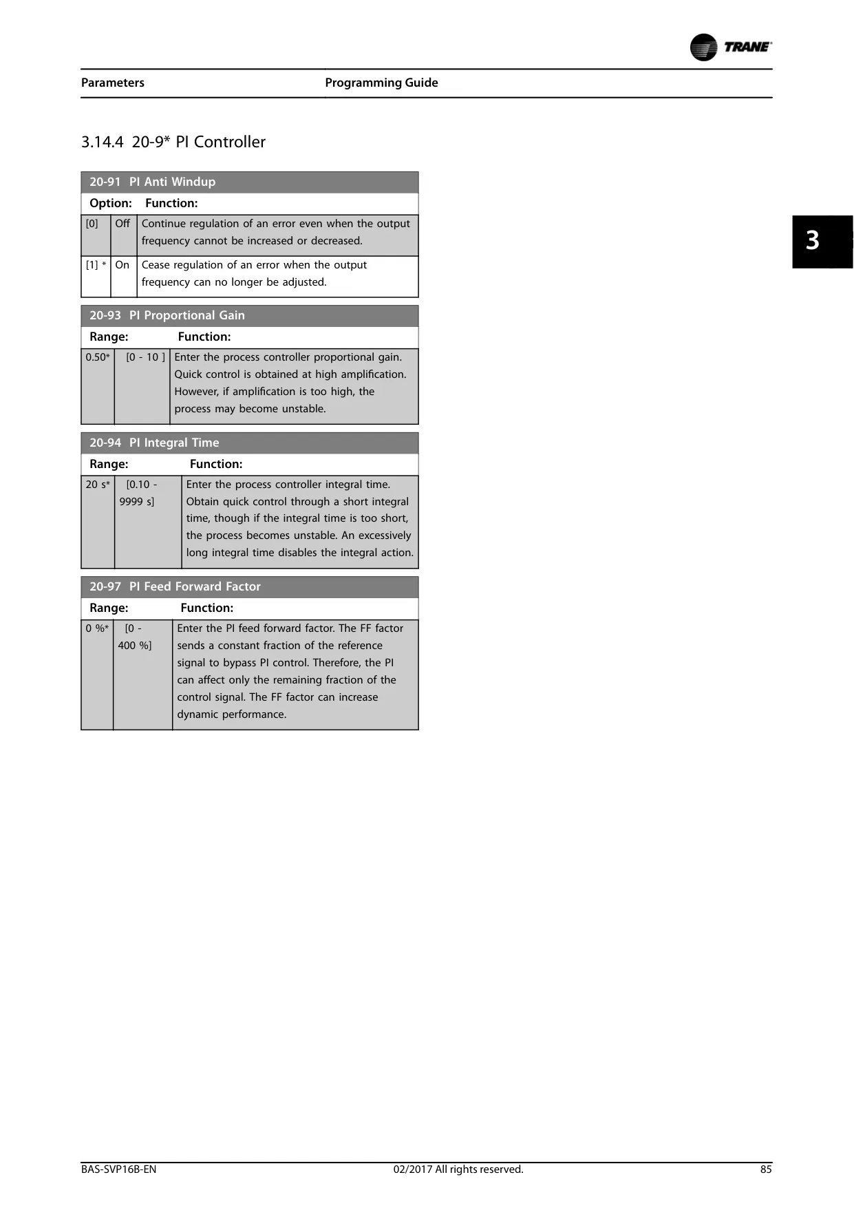
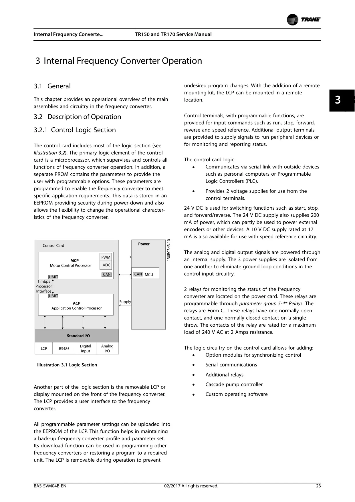
Internally, the TR170 VFD features a robust control logic section, powered by a microprocessor, which oversees and regulates all functions. This section utilizes a PROM for programmable options and an EEPROM to securely store user-defined parameters, ensuring flexibility and data retention even during power outages. This design allows for customization to meet specific application demands efficiently.
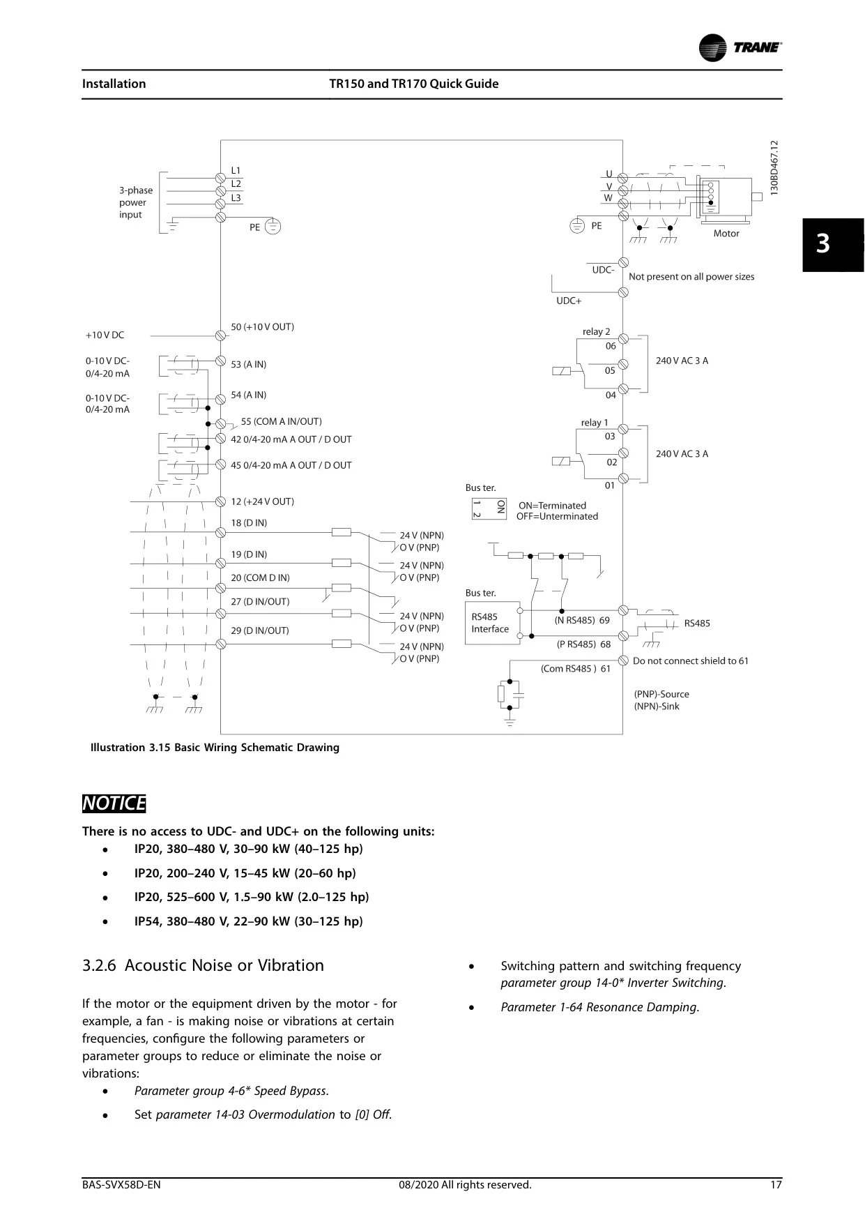
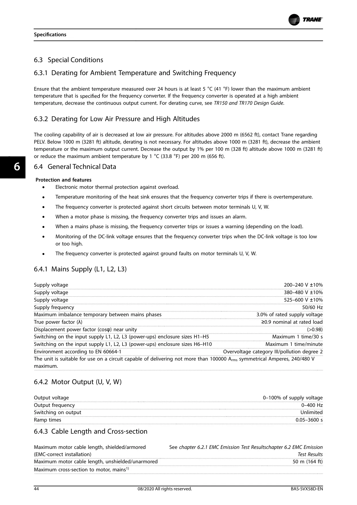
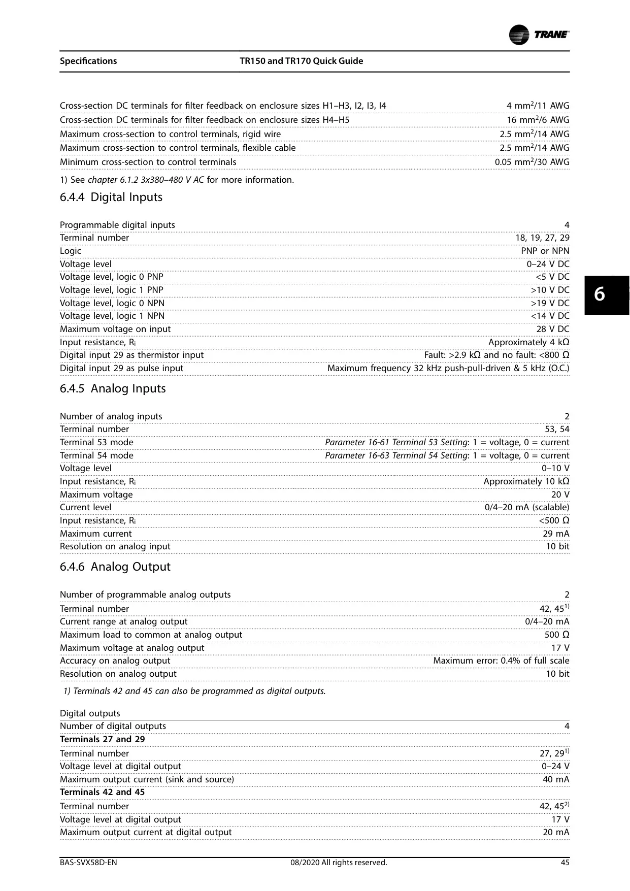
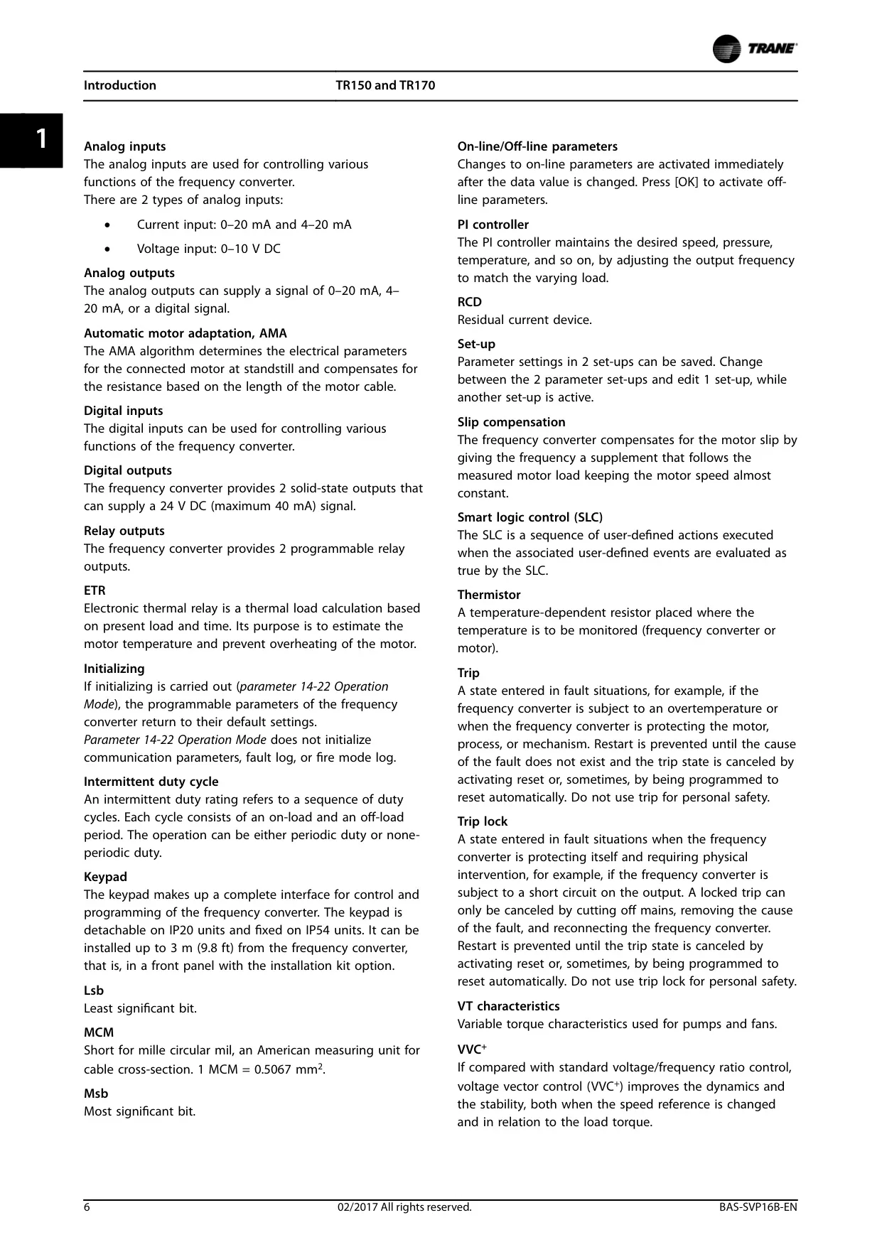
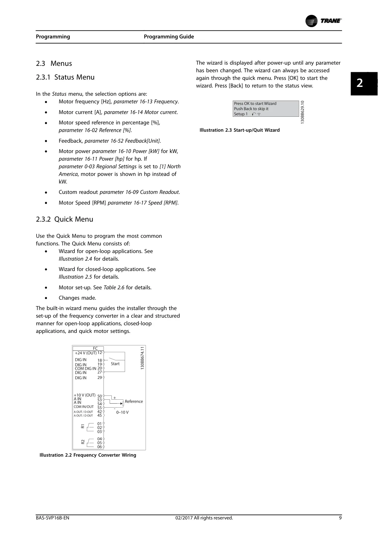
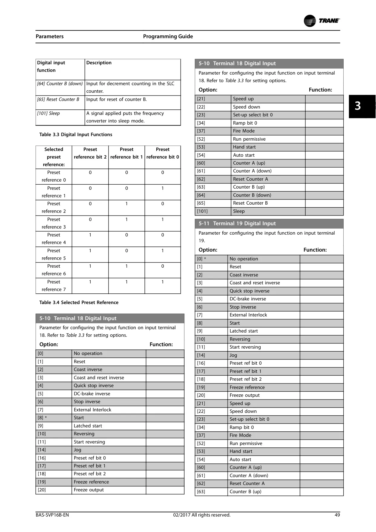
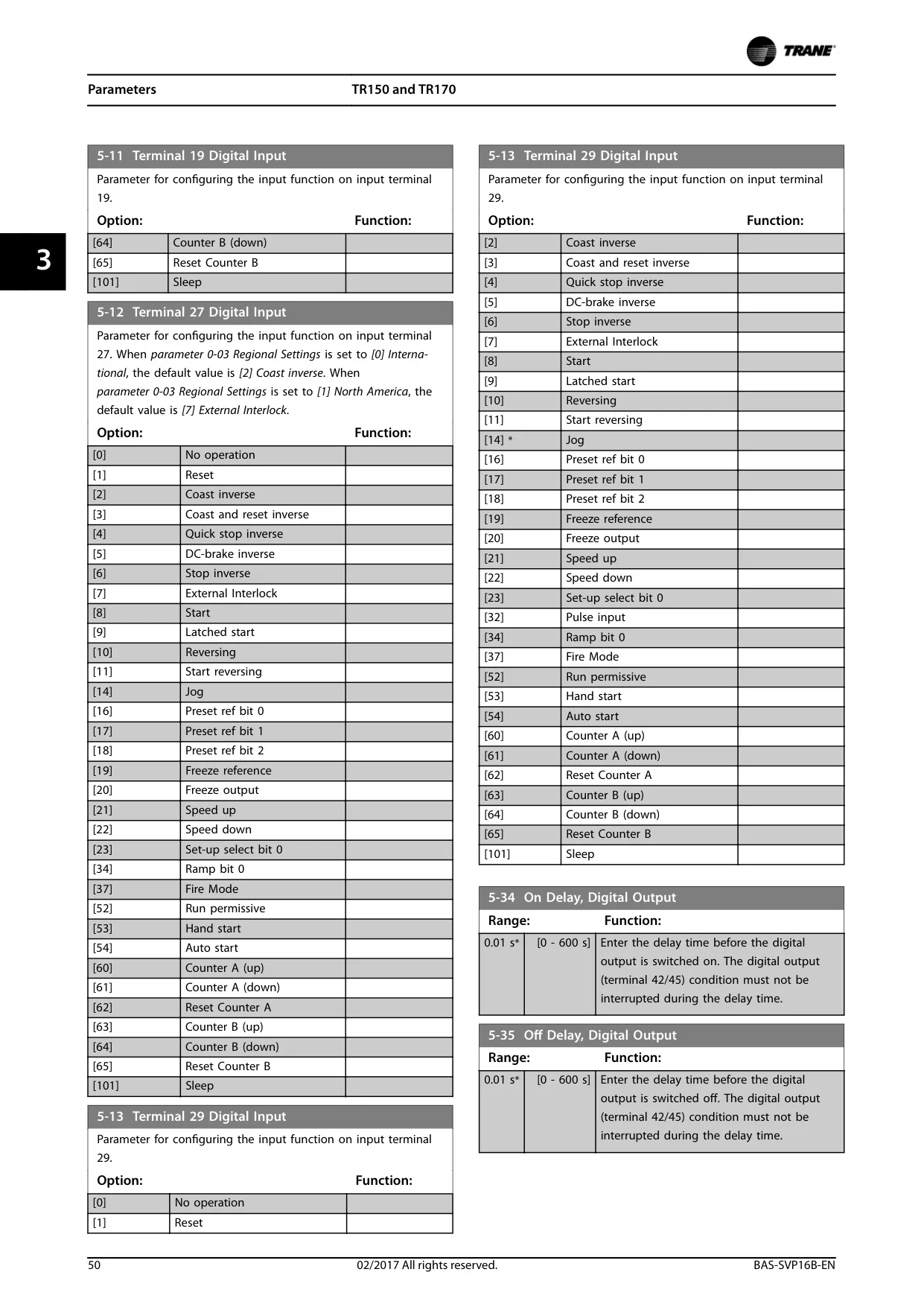
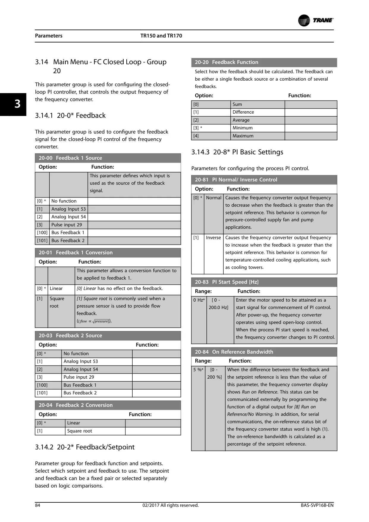
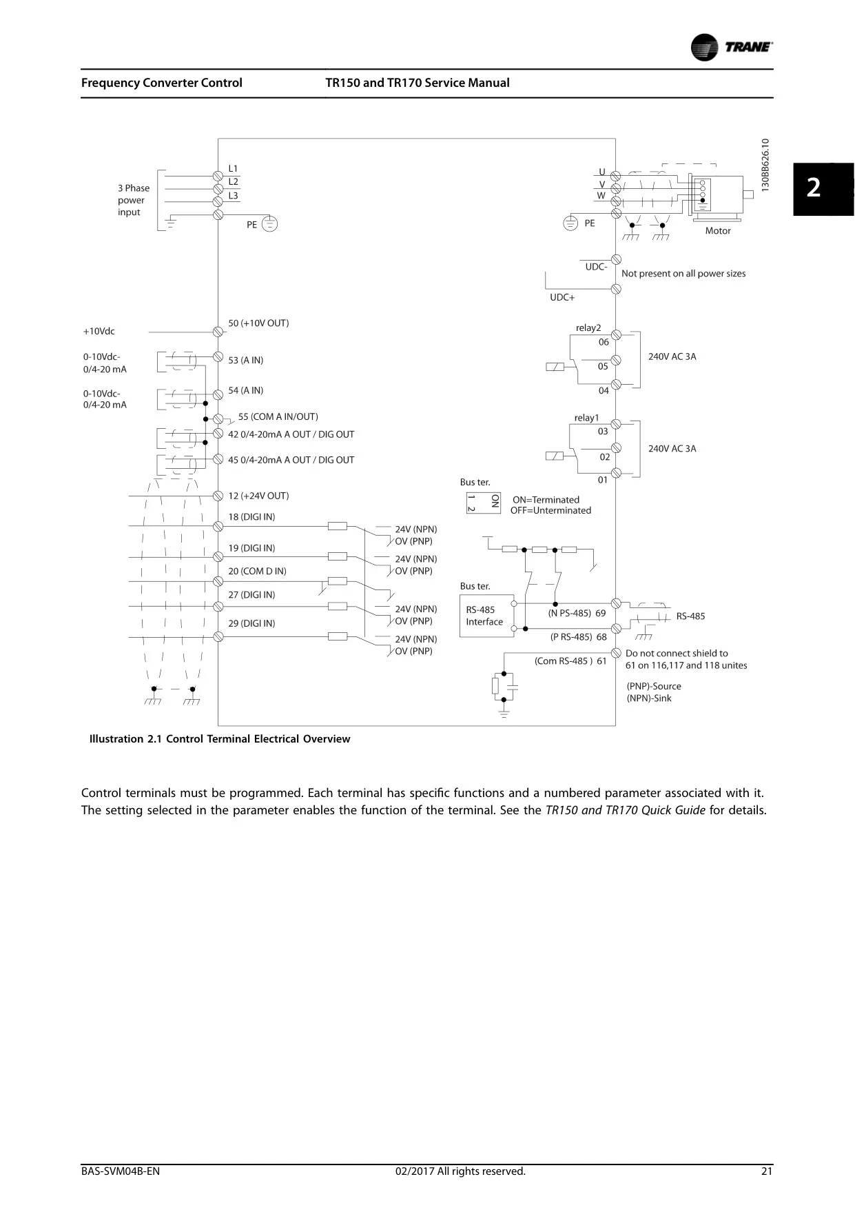
The device supports a variety of input and output signals for comprehensive control and monitoring. It can receive digital (0–24 V DC) and analog (0–10 V DC or 0/4–20 mA) input signals from external sensors or controllers. These inputs dictate start/stop commands, speed references, and other operational adjustments, allowing the VFD to respond dynamically to system requirements.
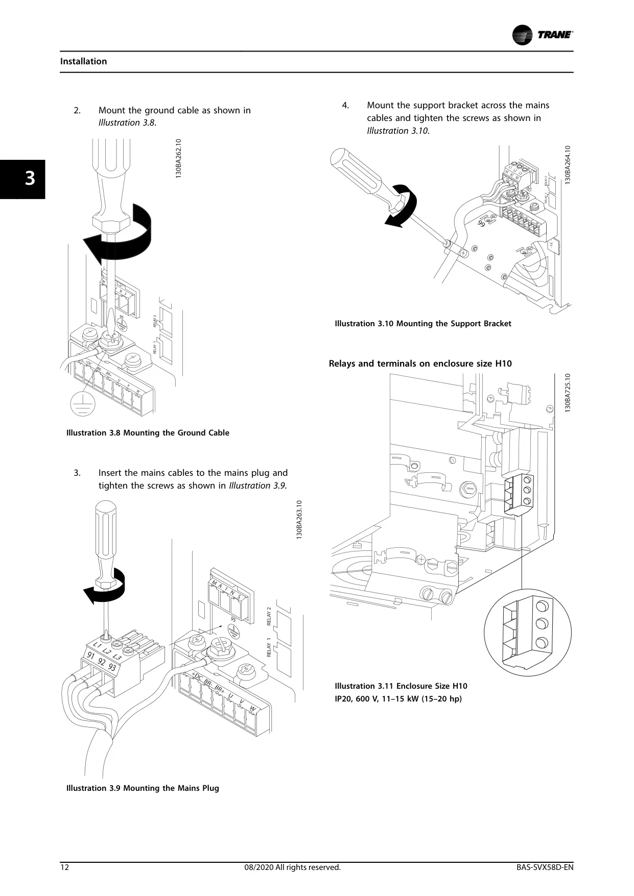
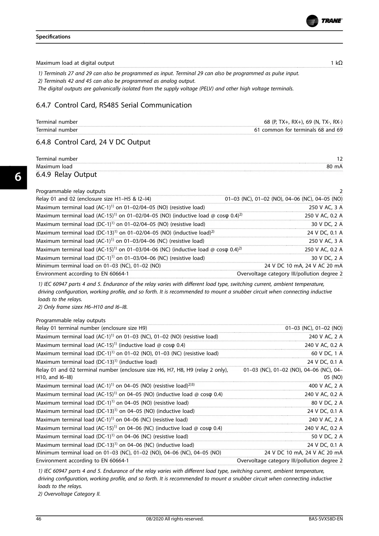
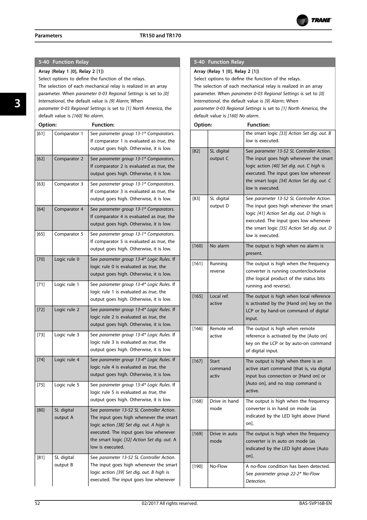
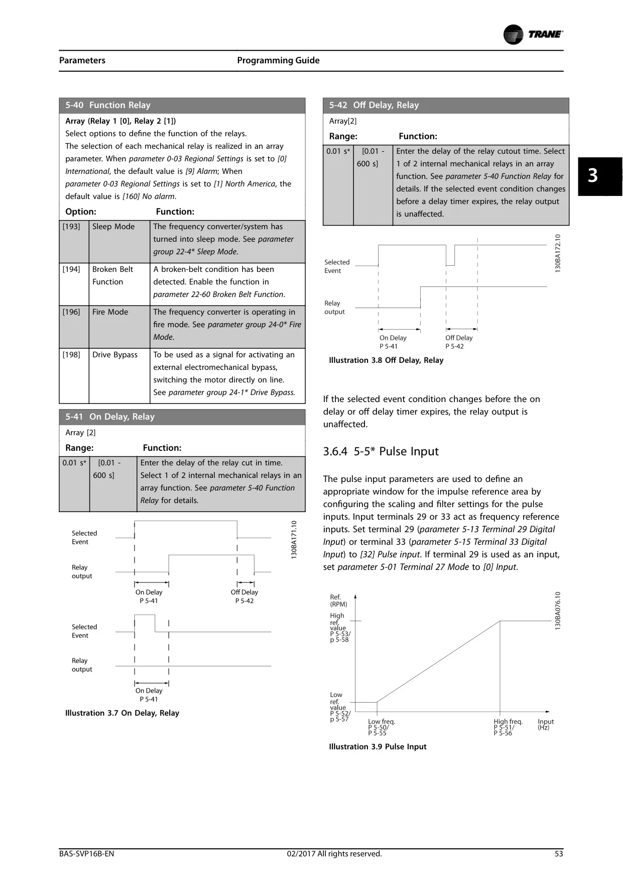
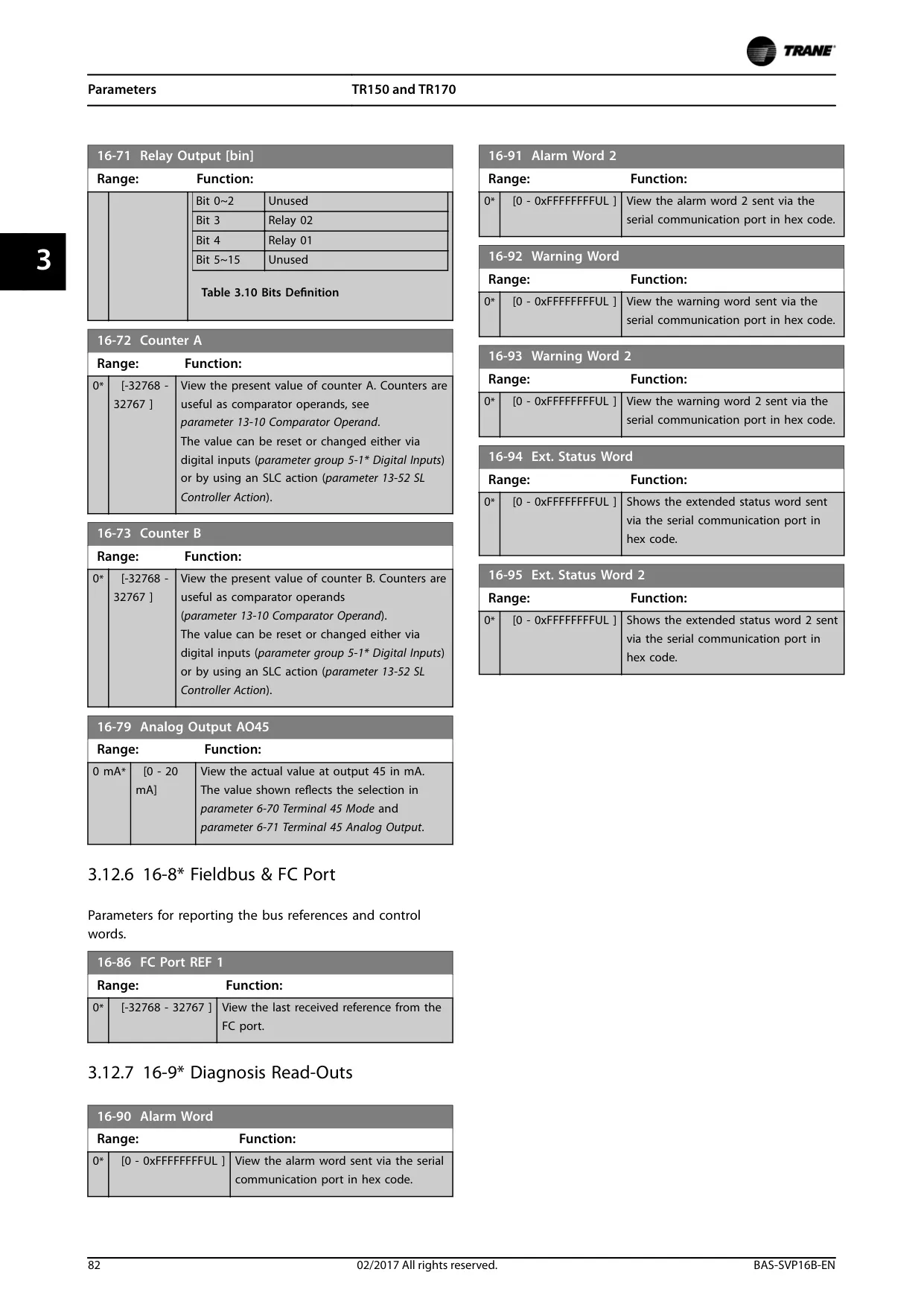
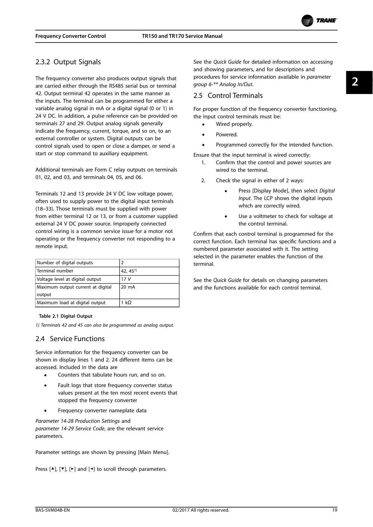
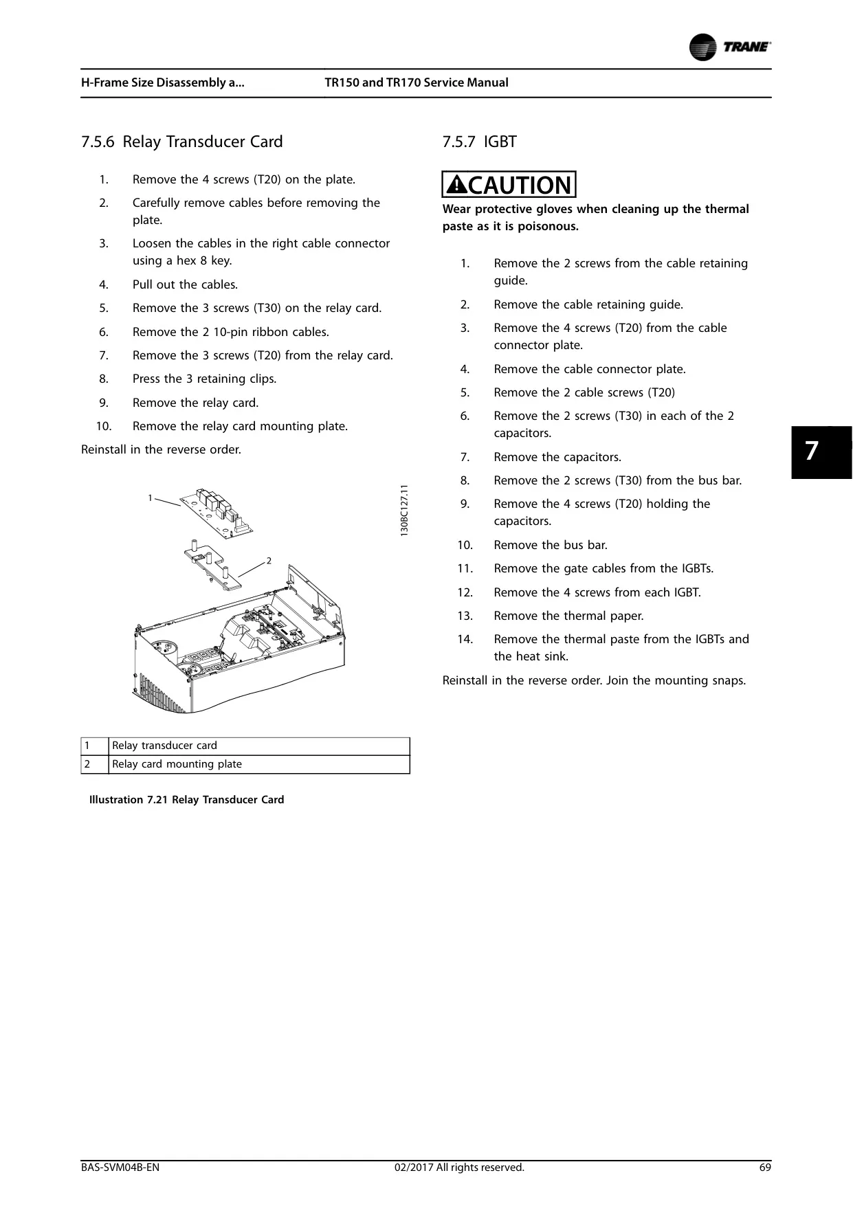
Output signals from the TR170 VFD, available via the RS485 serial bus or specific terminals, provide critical data such as frequency, current, and torque to external systems. Additionally, configurable Form C relay outputs allow the VFD to control auxiliary equipment or report status, integrating seamlessly into broader building management systems. Proper wiring and parameter programming are crucial for these functionalities.
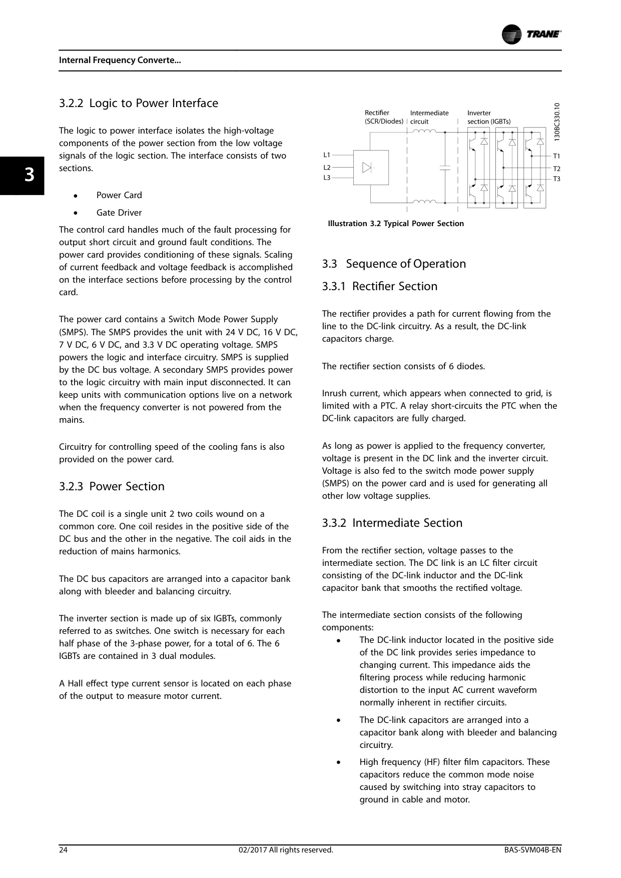
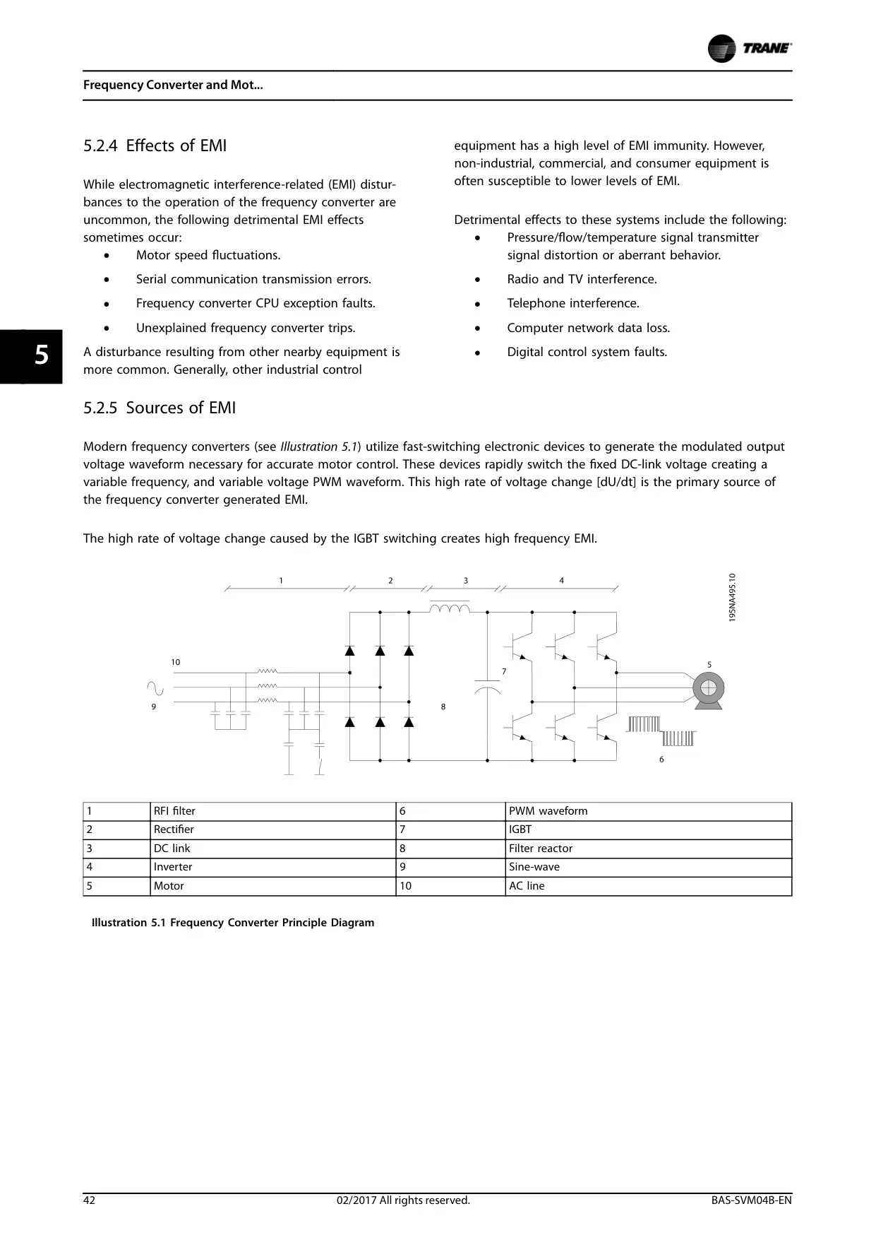
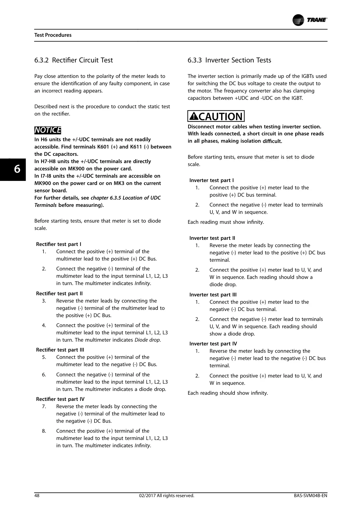
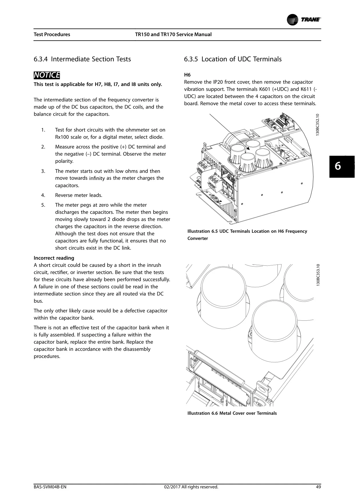
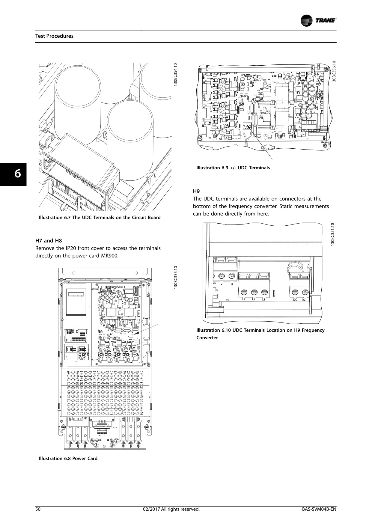
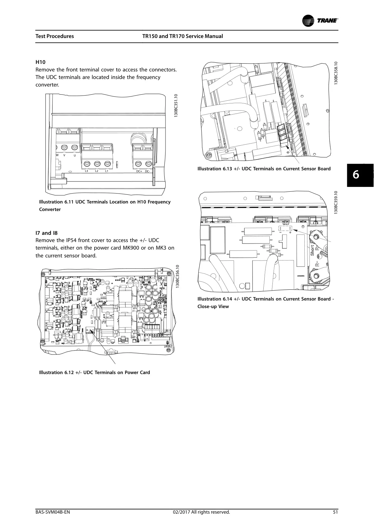
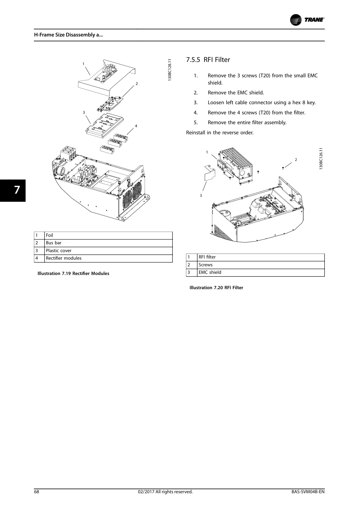
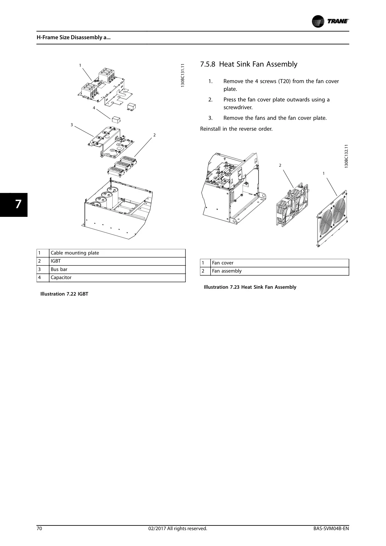
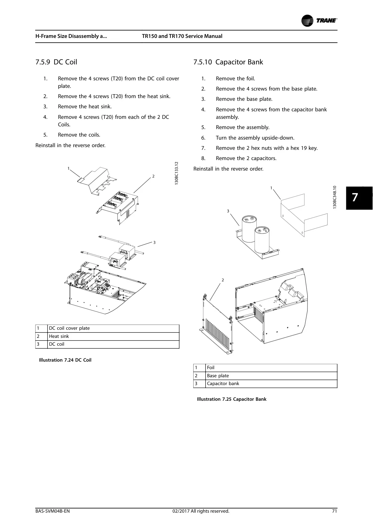
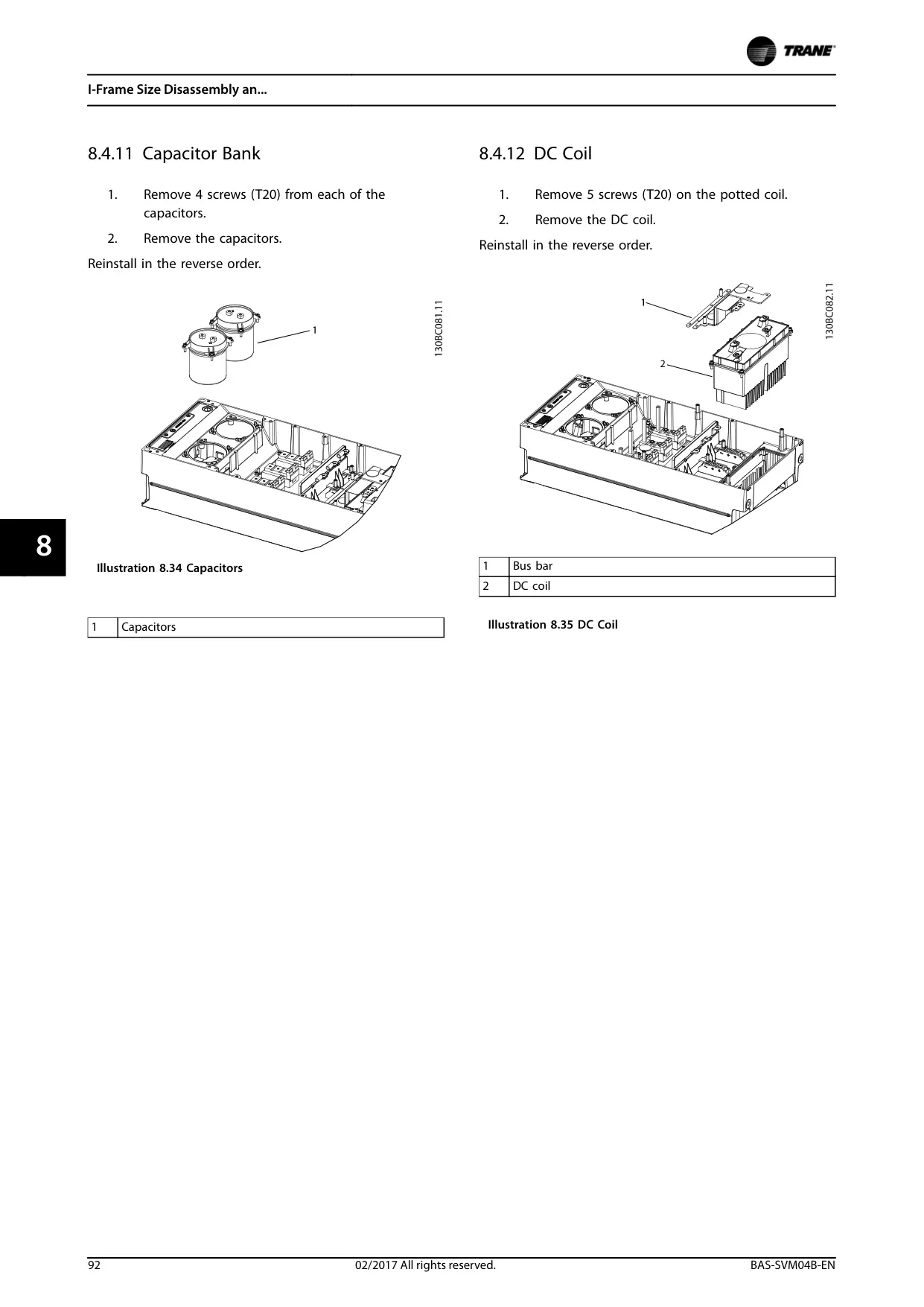
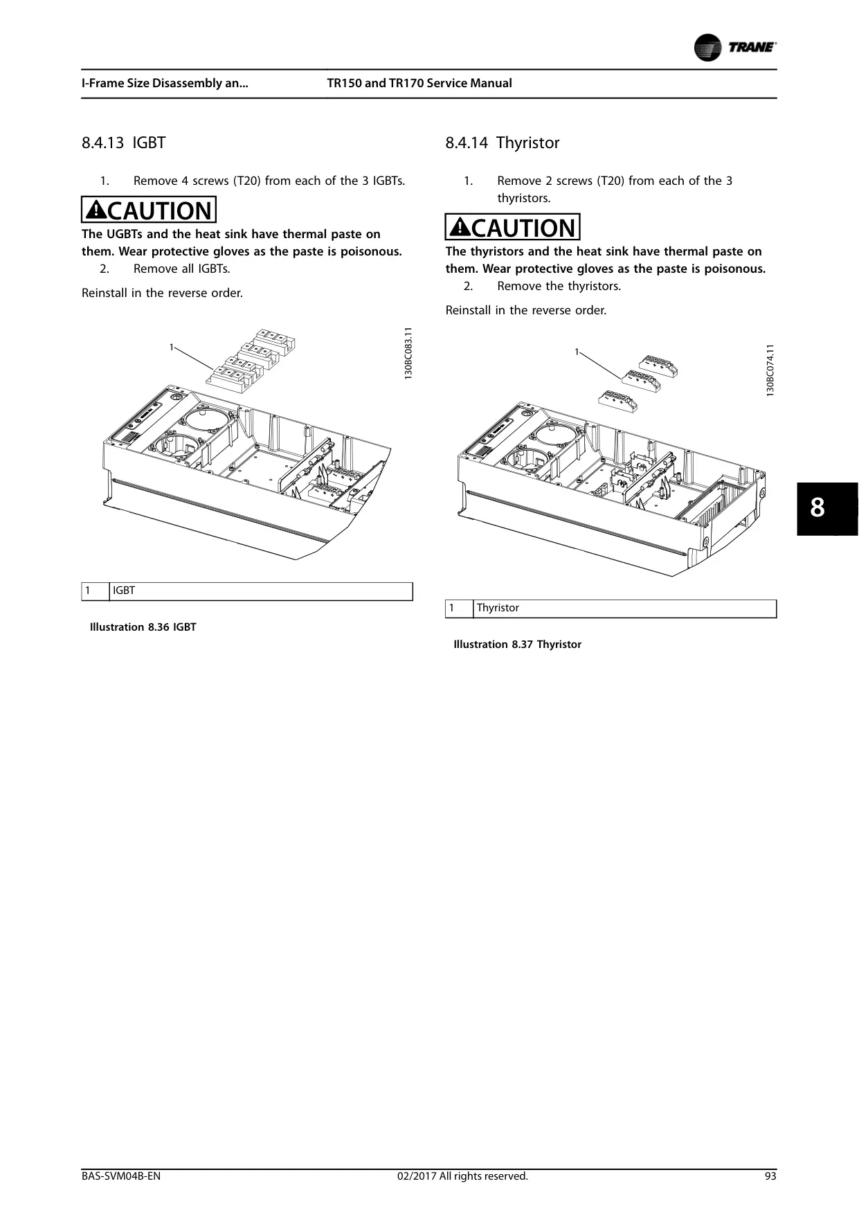
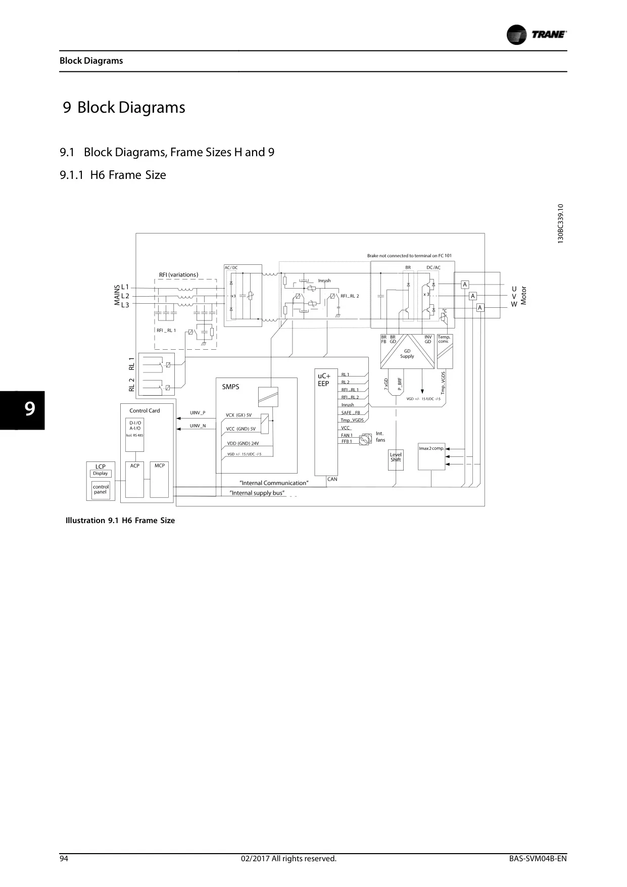
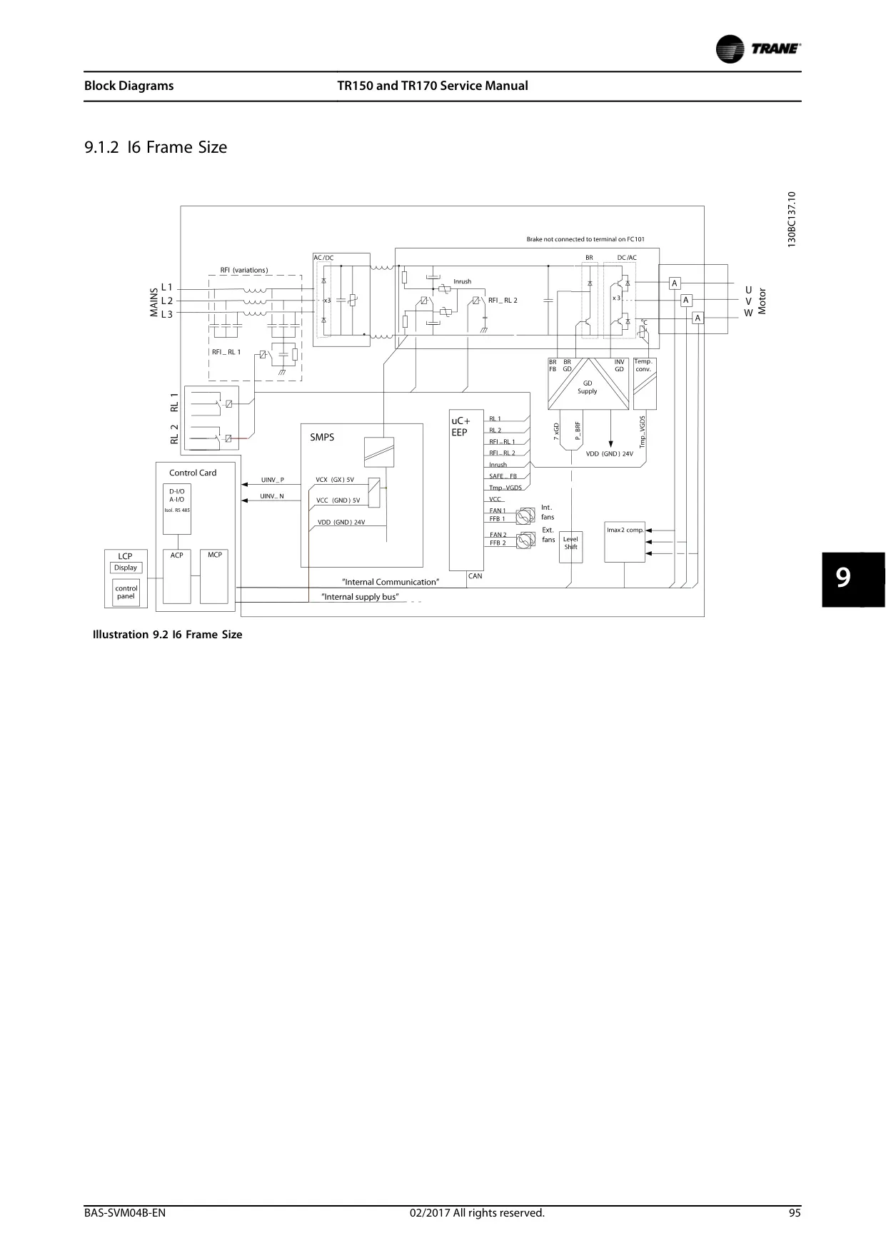
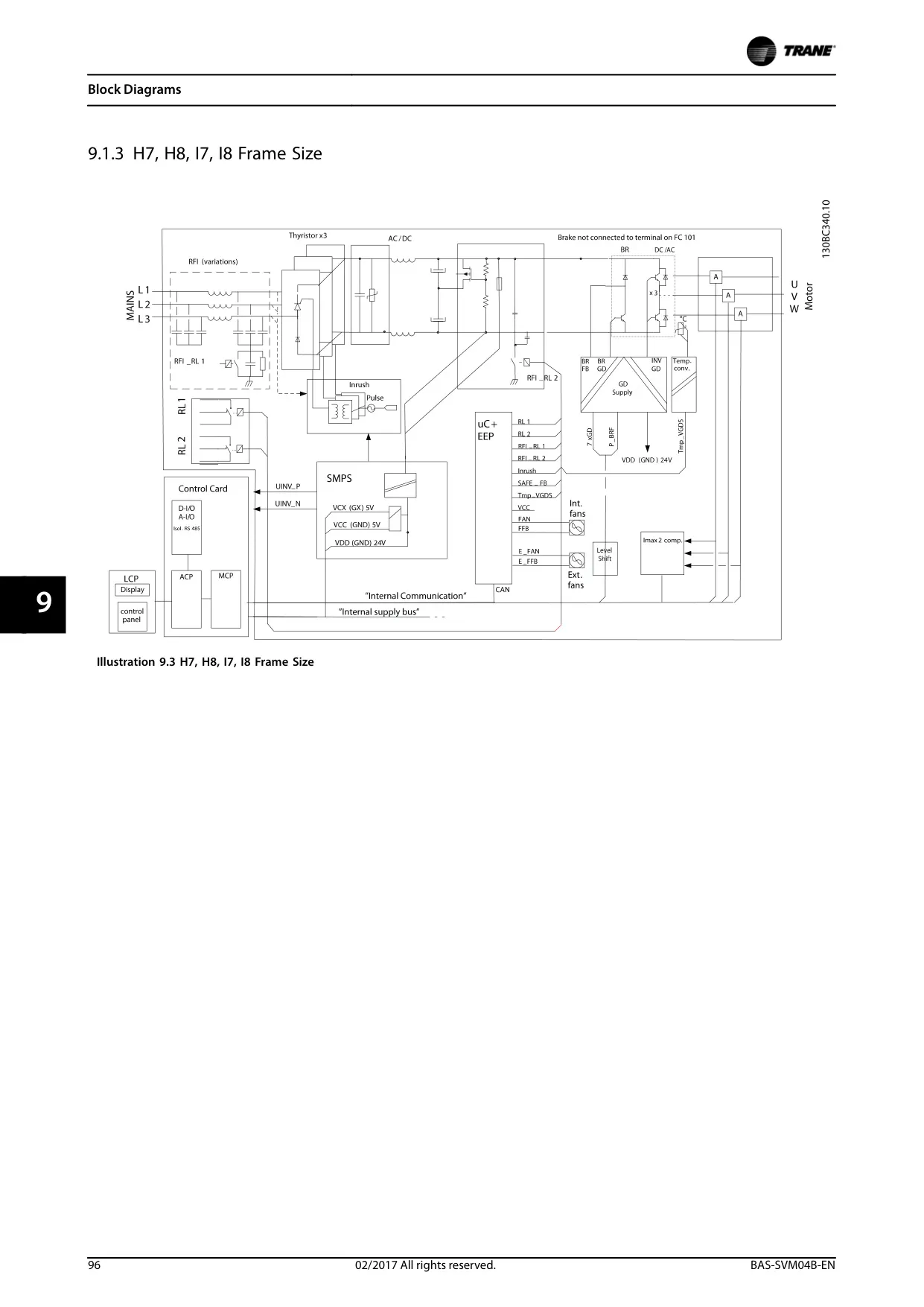
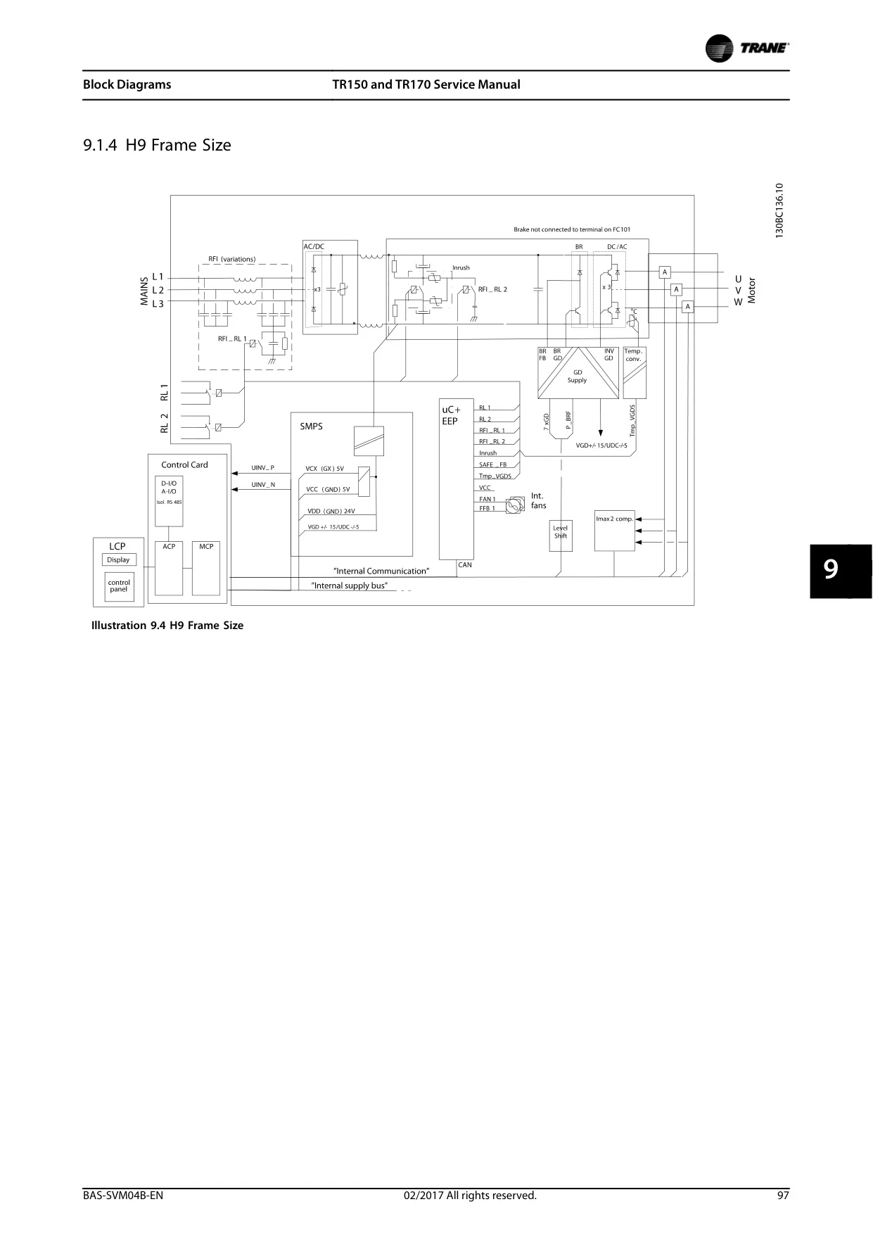
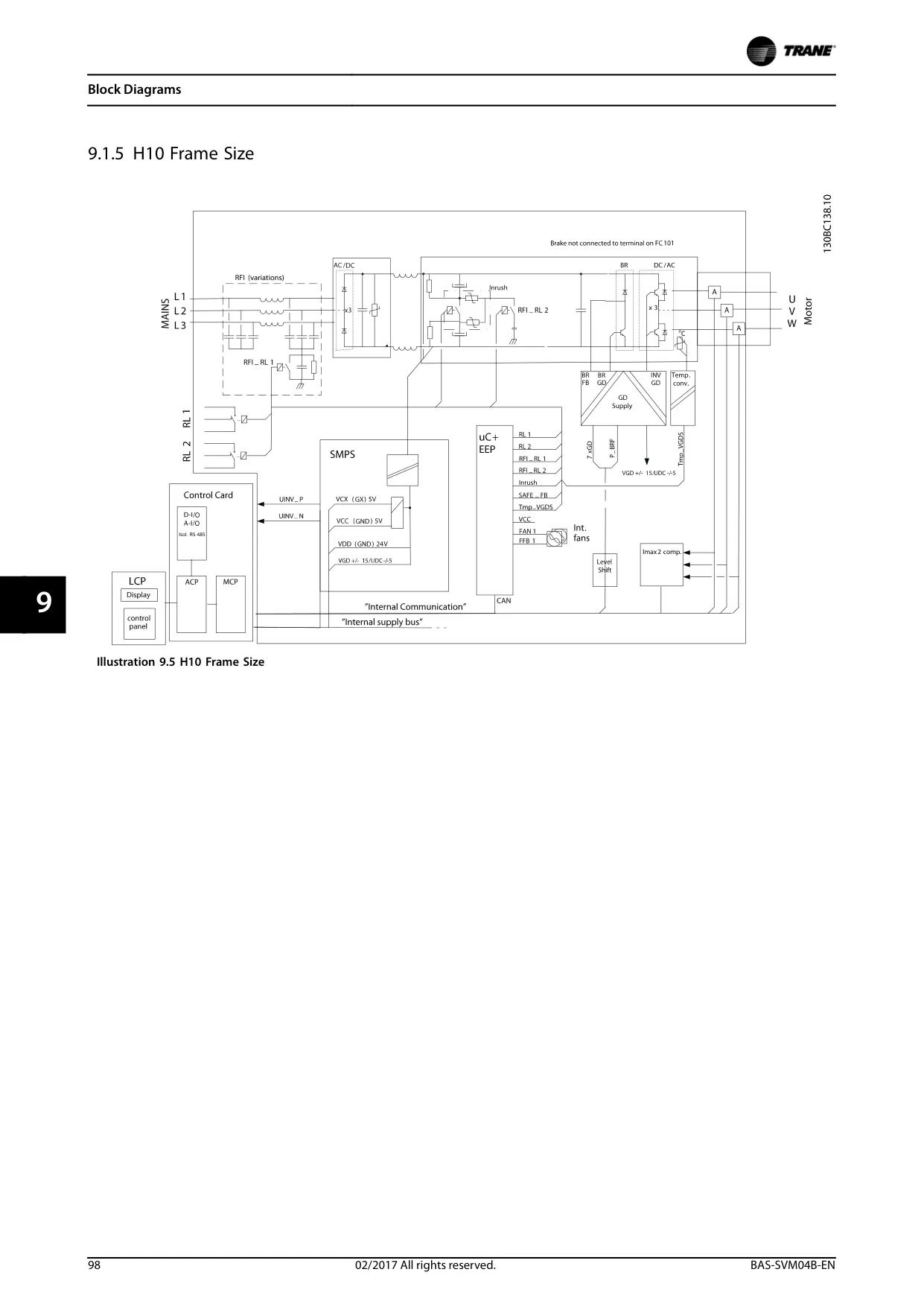
The internal operation includes a sophisticated power section, featuring a rectifier for AC-to-DC conversion, an intermediate DC link with DC coils and capacitor banks for voltage smoothing, and an inverter section equipped with IGBTs (Insulated Gate Bipolar Transistors) for precise motor control. These components work in sequence to convert input power into the variable frequency output required by the motor.
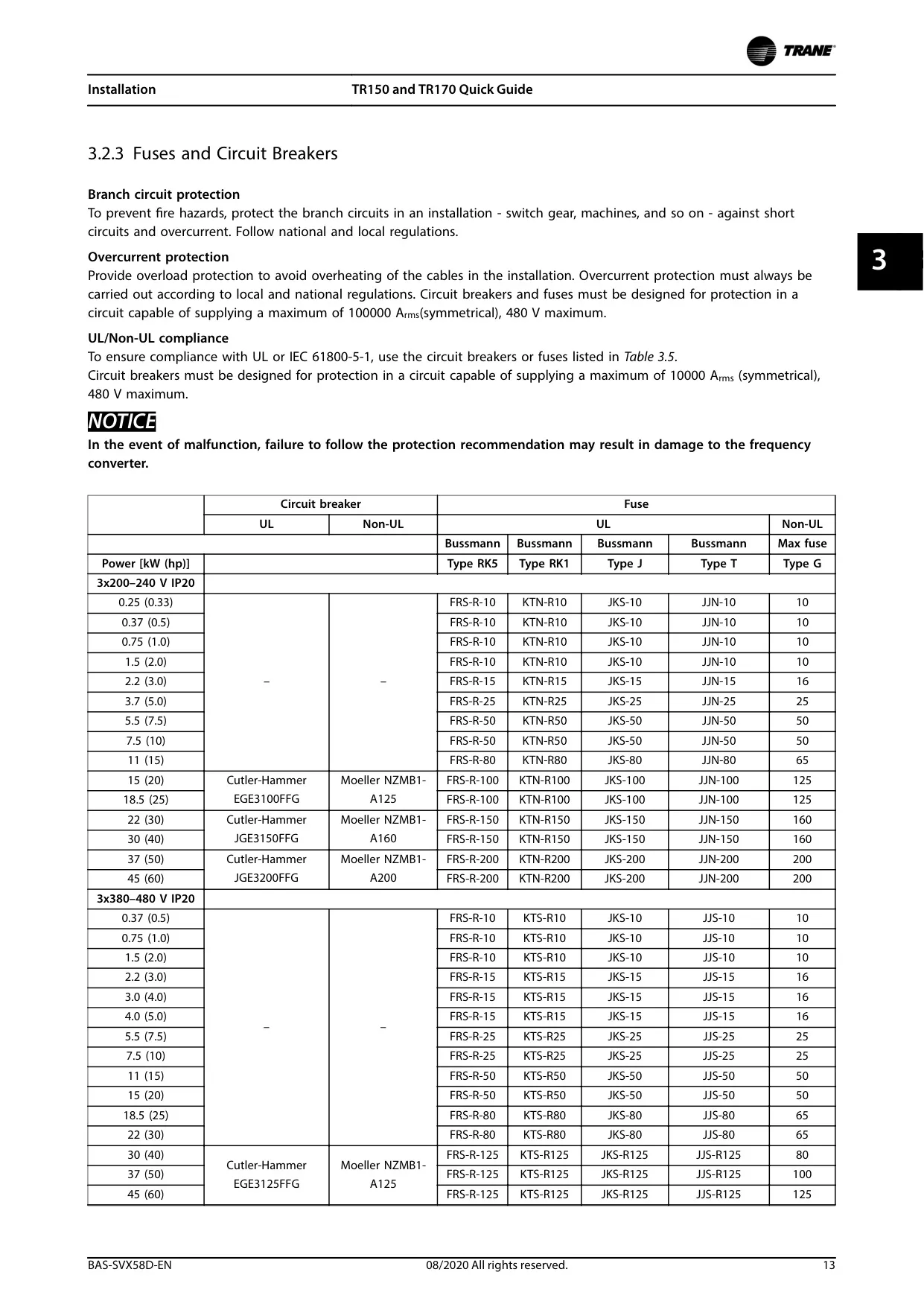
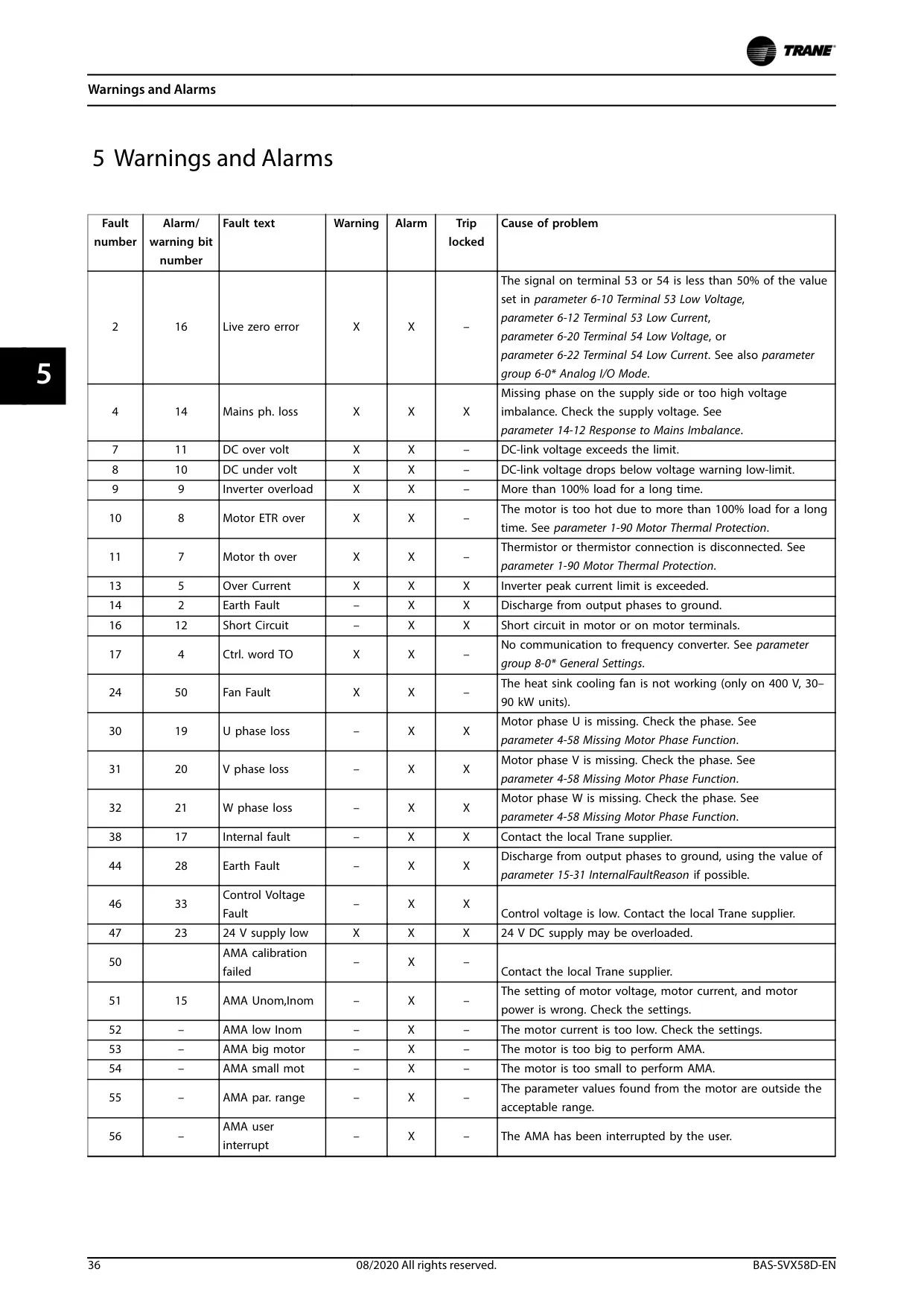
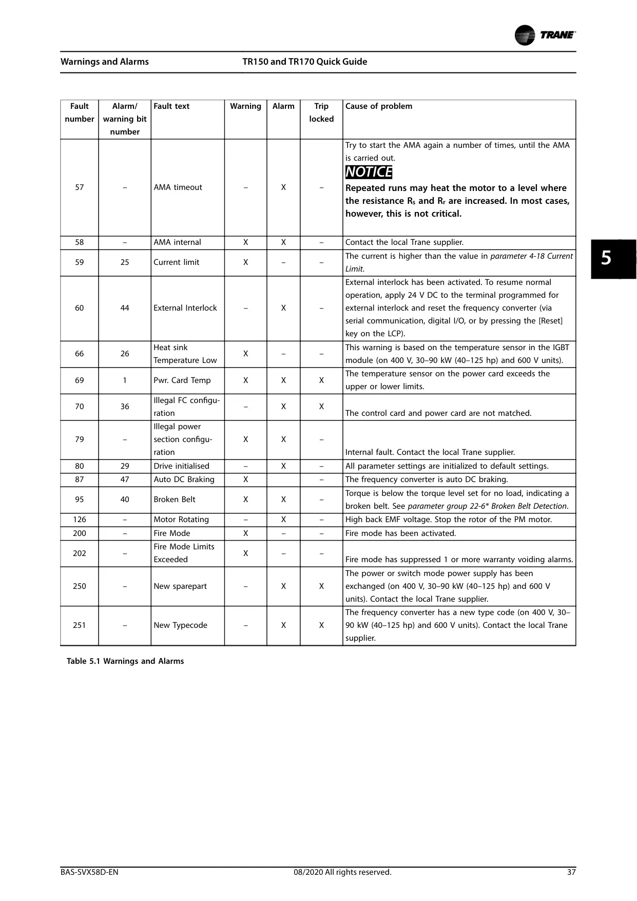
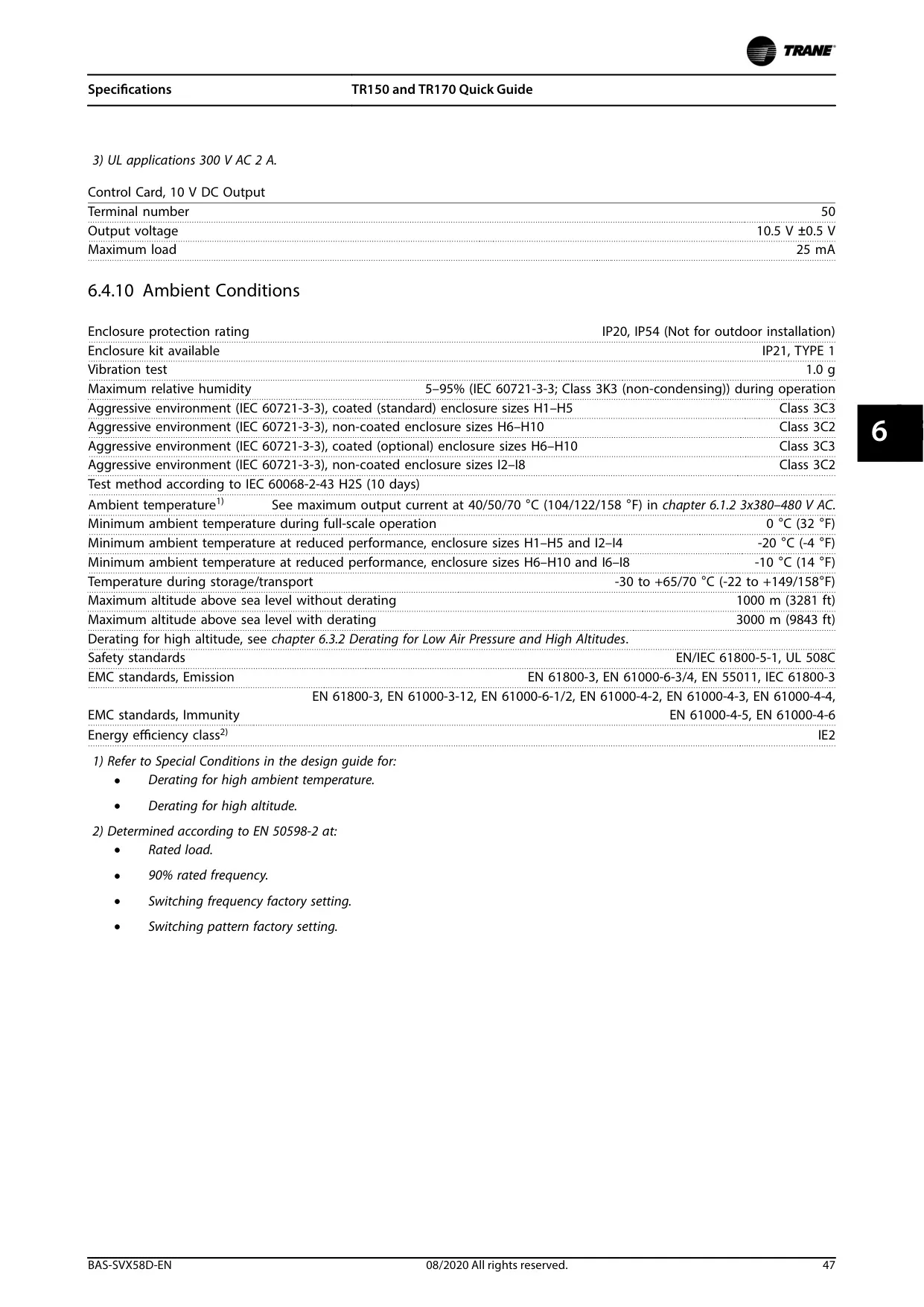
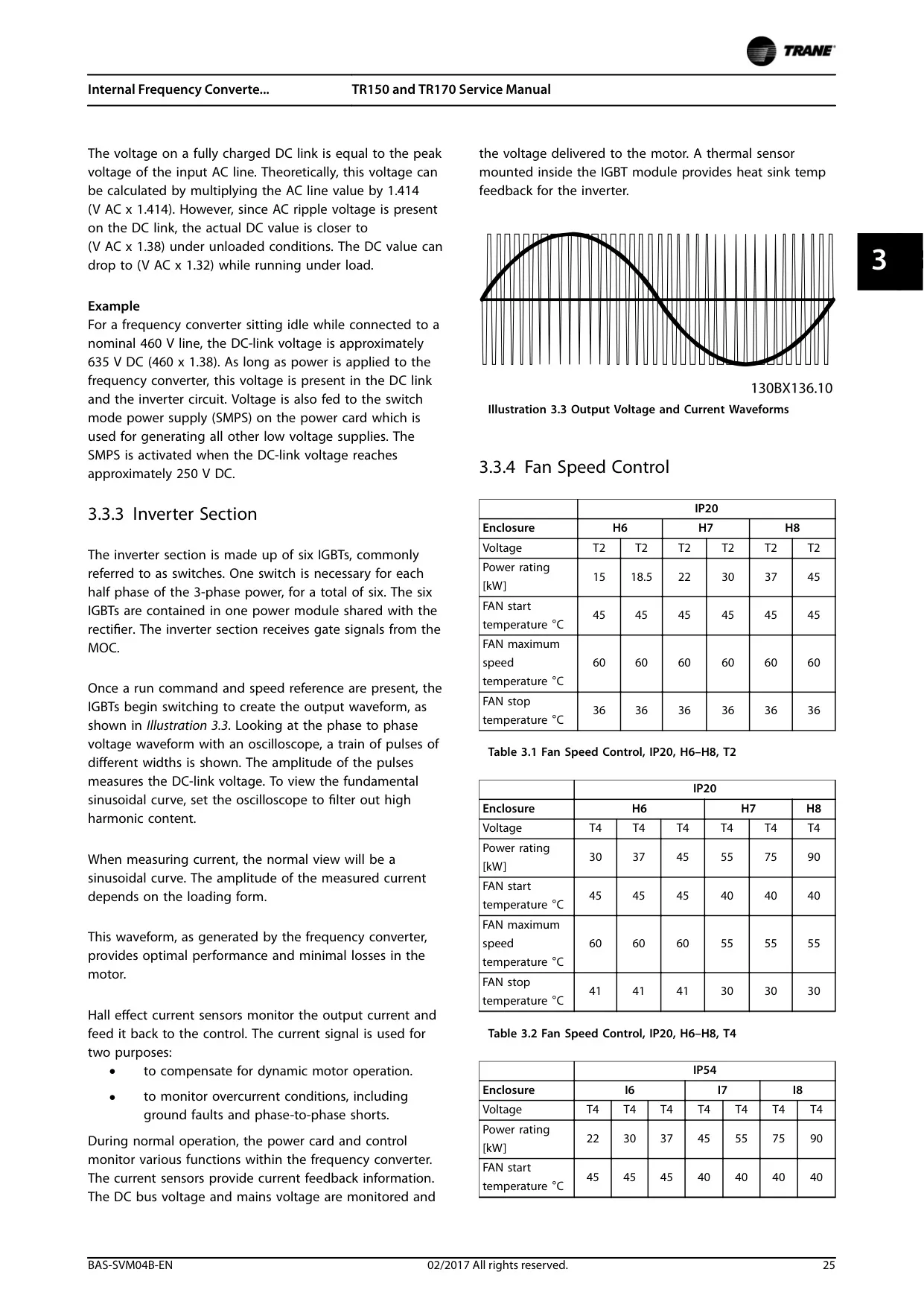
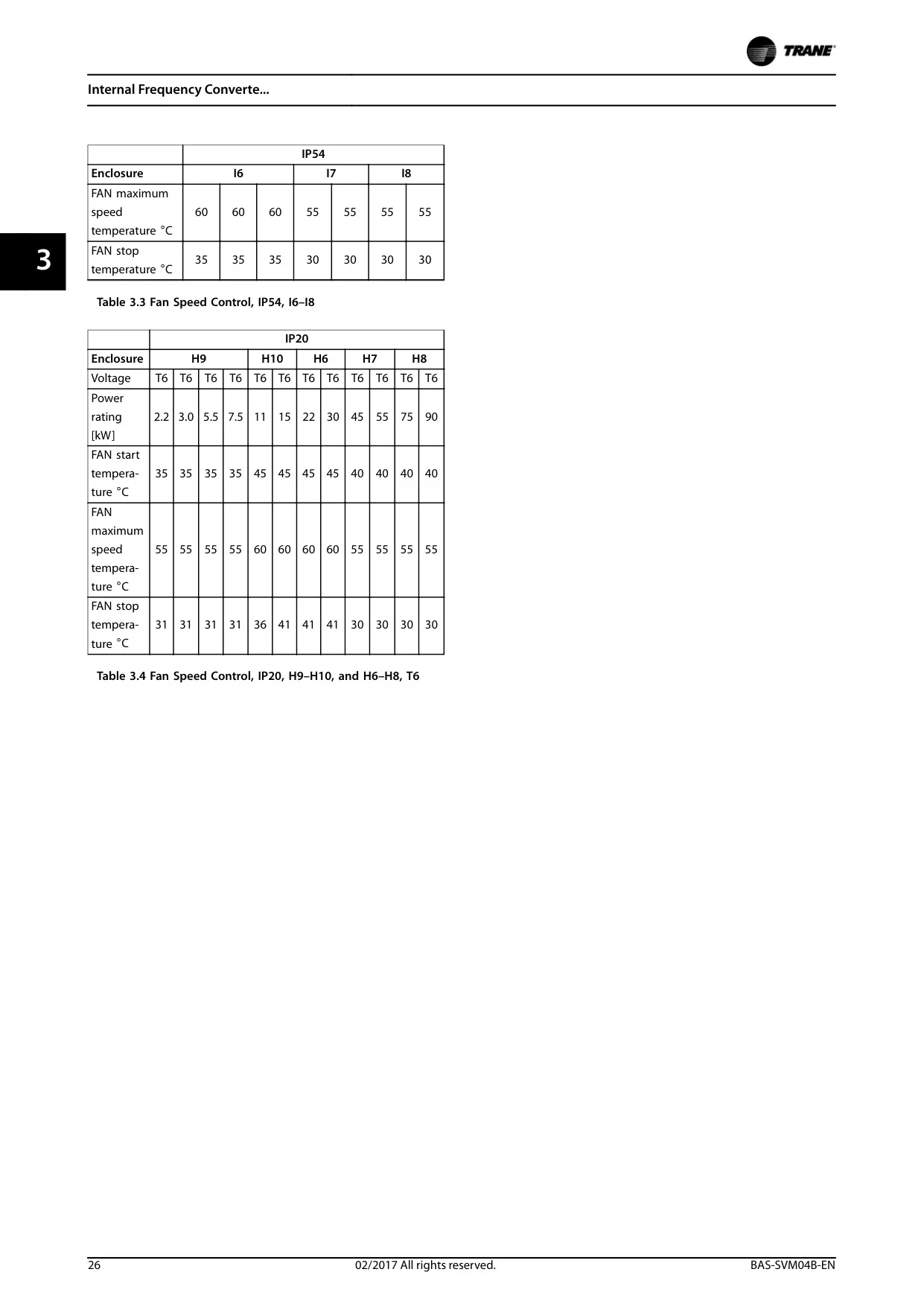
Furthermore, the TR170 VFD incorporates features like fan speed control based on internal temperature sensors, which helps in maintaining optimal operating conditions and extending component life. It also includes comprehensive protection mechanisms, such as short-circuit and overcurrent trips, ensuring safe operation and safeguarding the motor and the VFD itself from potential damage.
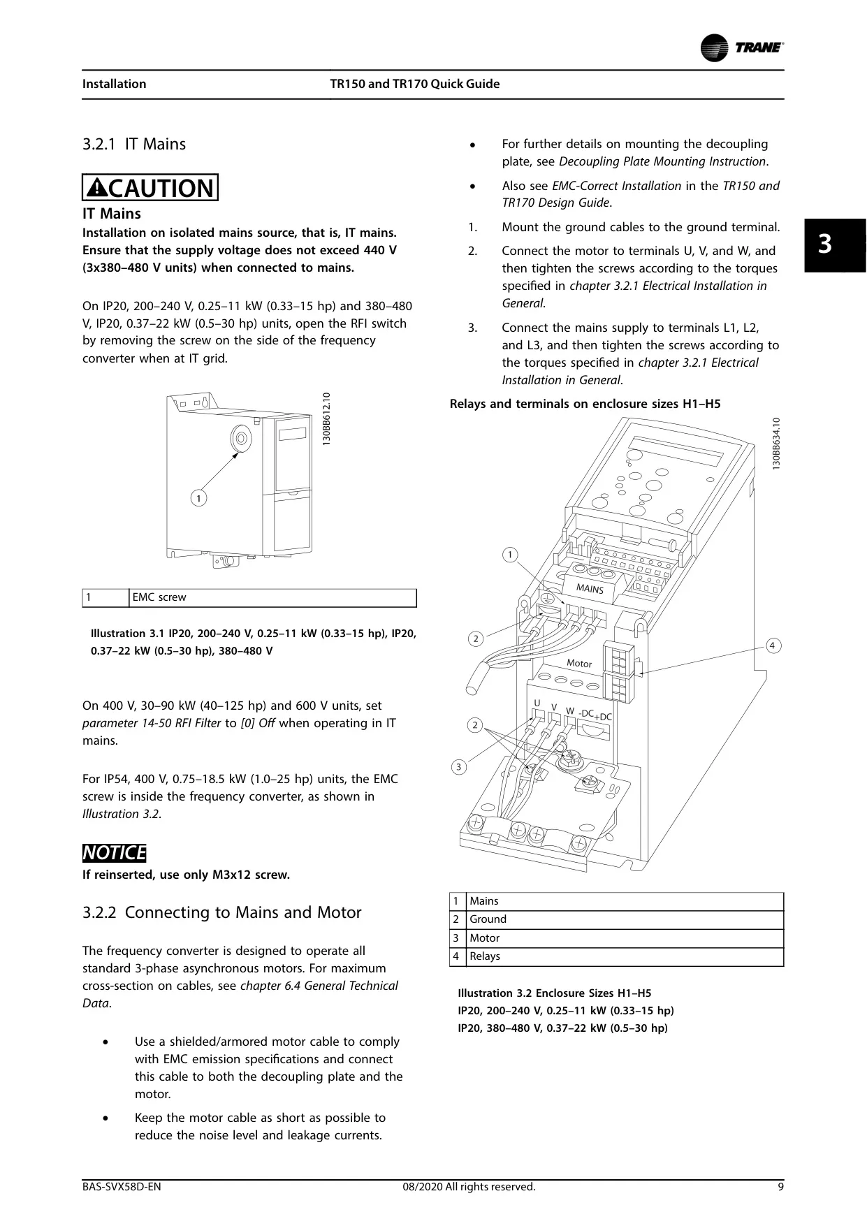
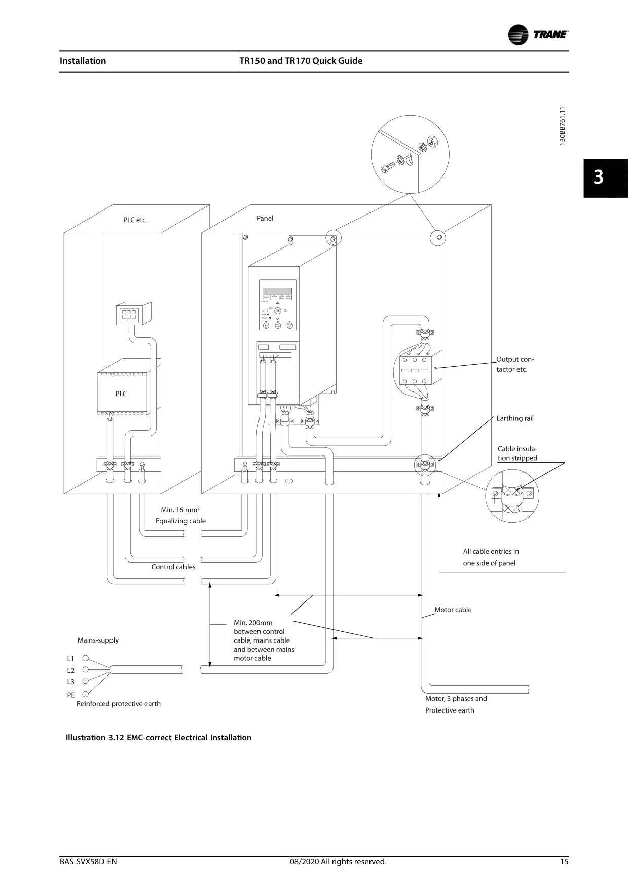
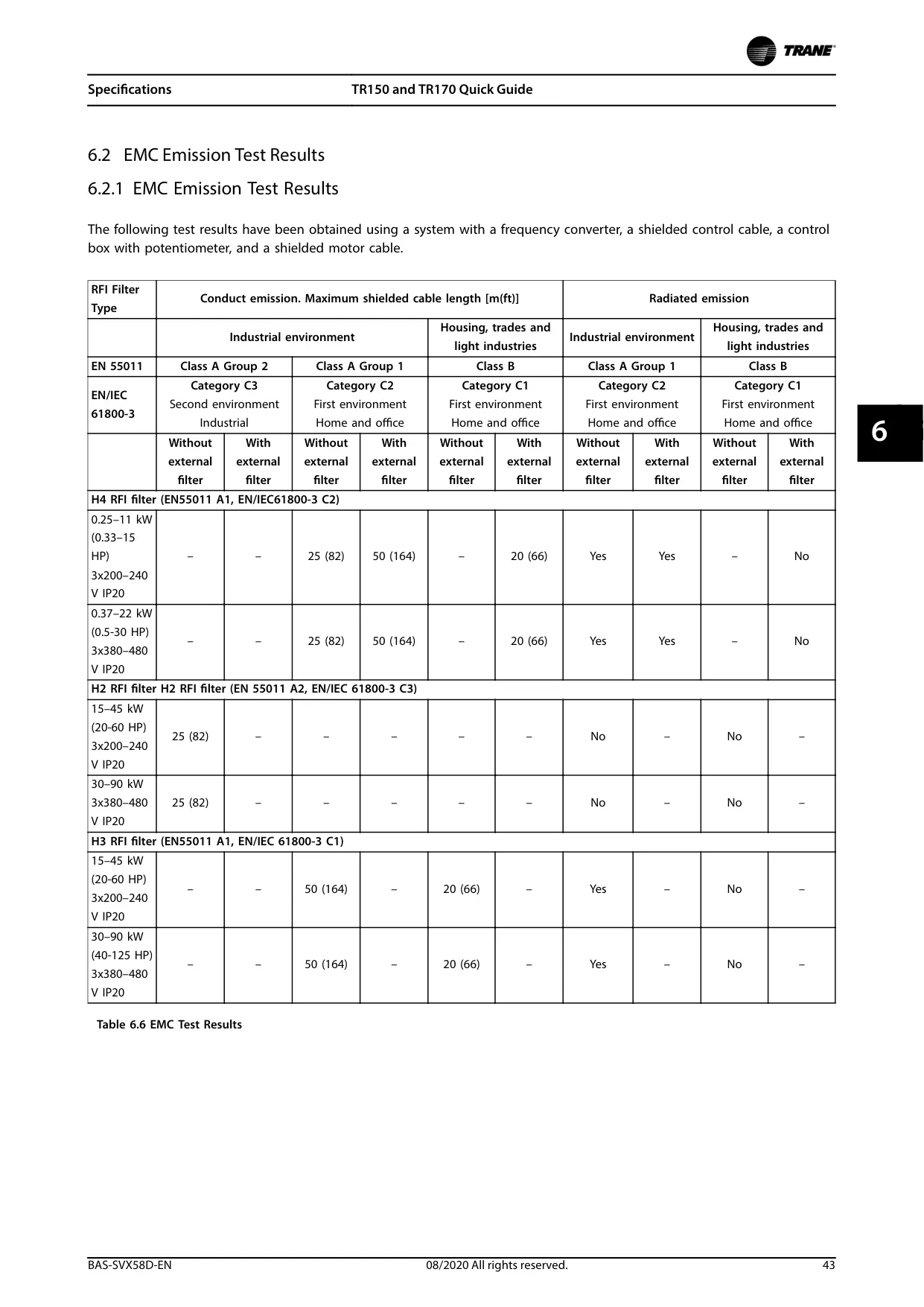
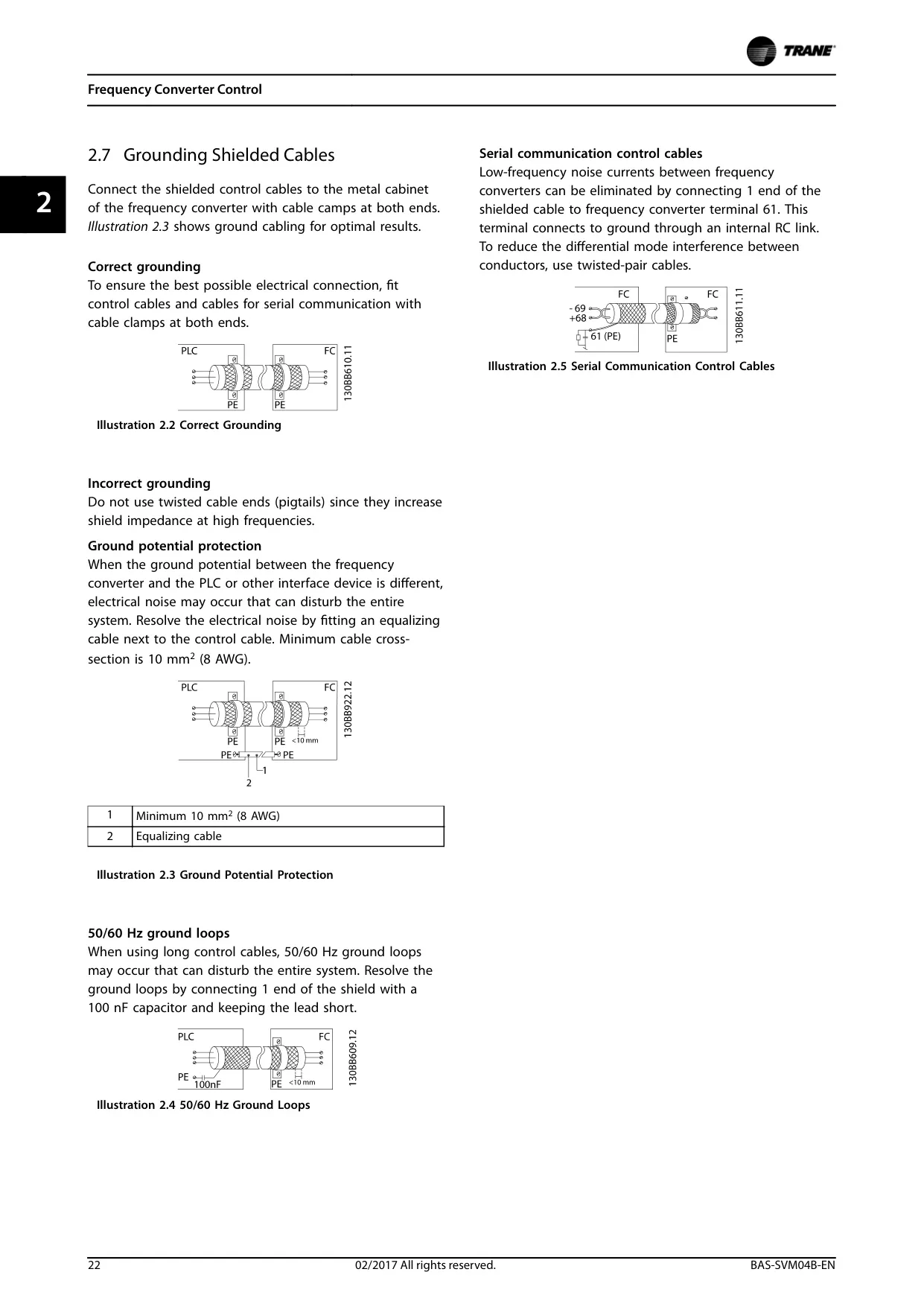
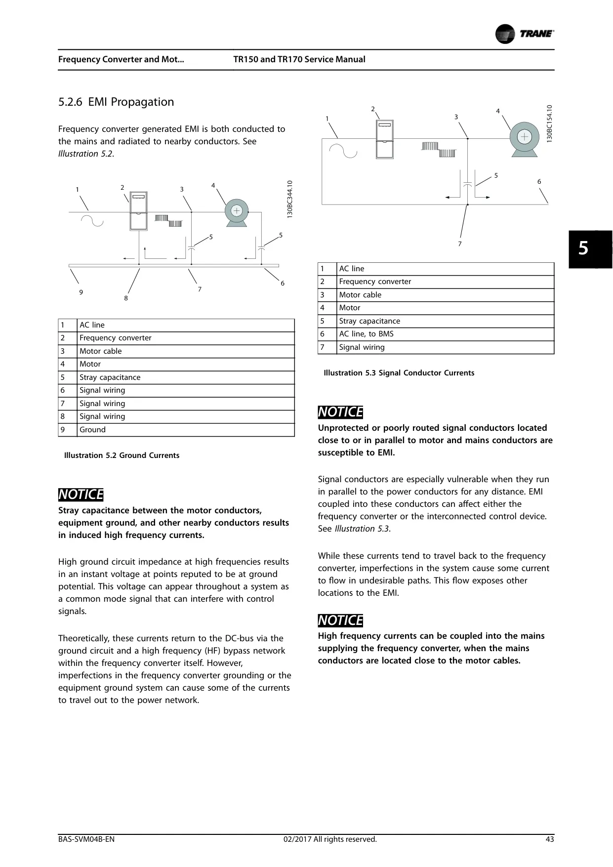
The design also emphasizes electromagnetic compatibility (EMC) through measures like RFI filters and proper grounding guidelines. These considerations are vital for preventing EMI (electromagnetic interference) that could disrupt sensitive electronic components, both within the VFD and in adjacent control systems, ensuring reliable performance in industrial and commercial environments.
Frequently Asked Questions (FAQs)
Can't find the answer you need? Here are some frequently asked questions about the Trane TR170 VFD, and we answer them below.