Trane TR200 Variable Frequency Drive Instruction Manual
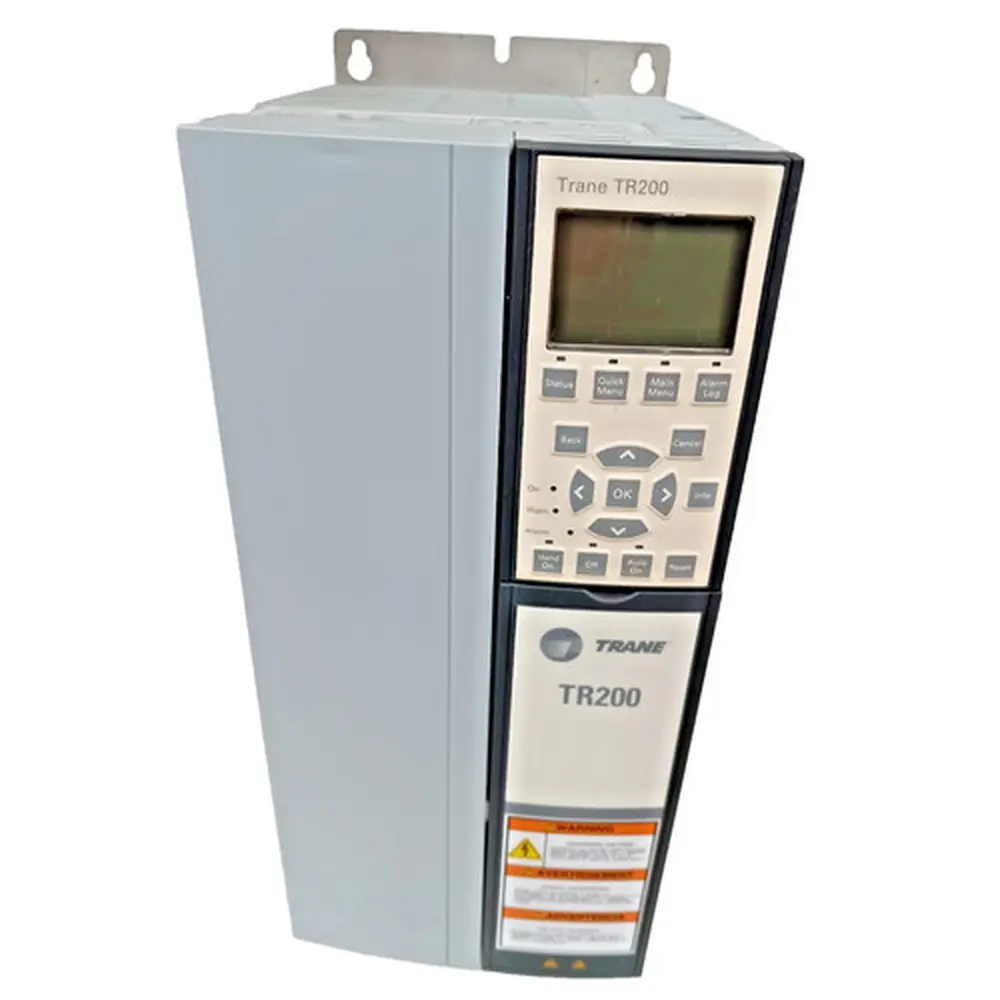
Trane TR200 Variable Frequency Drive


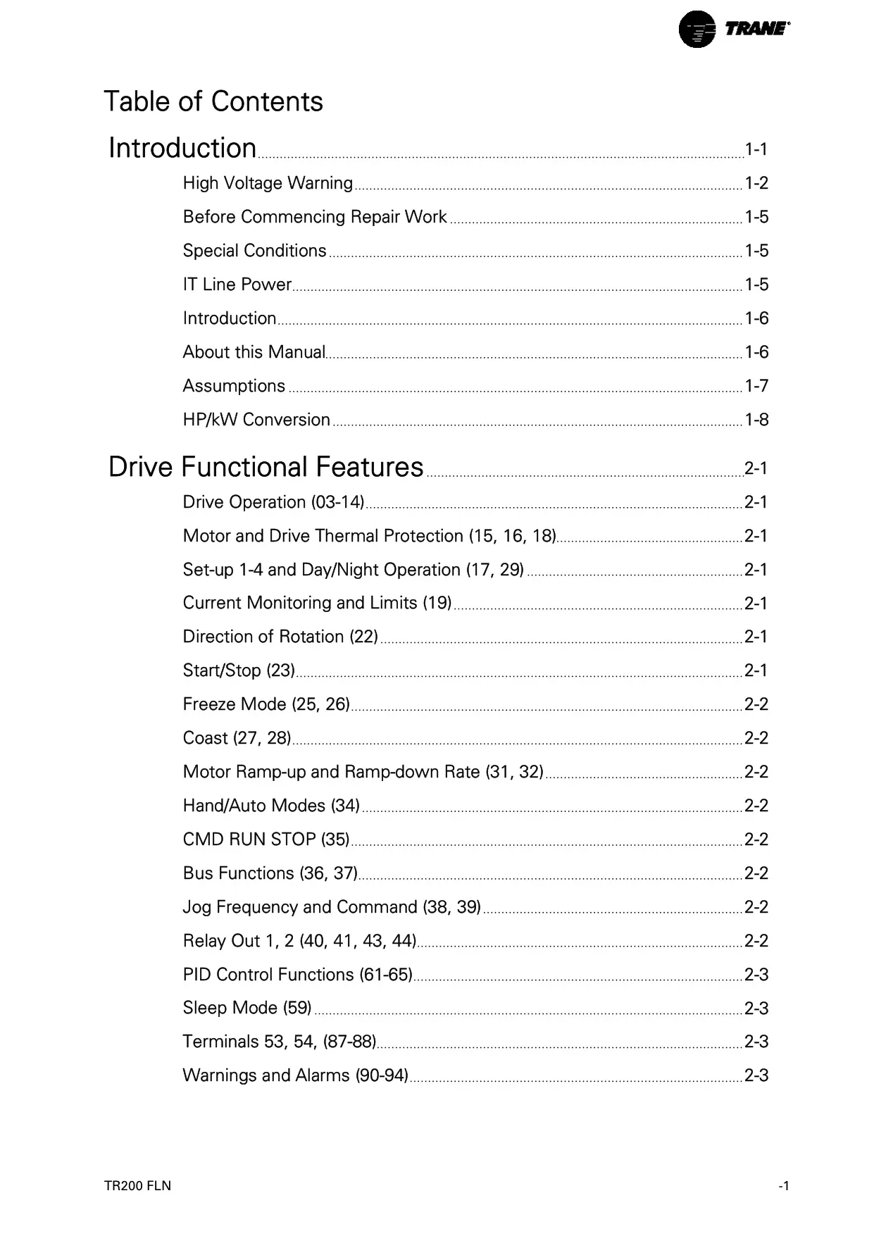
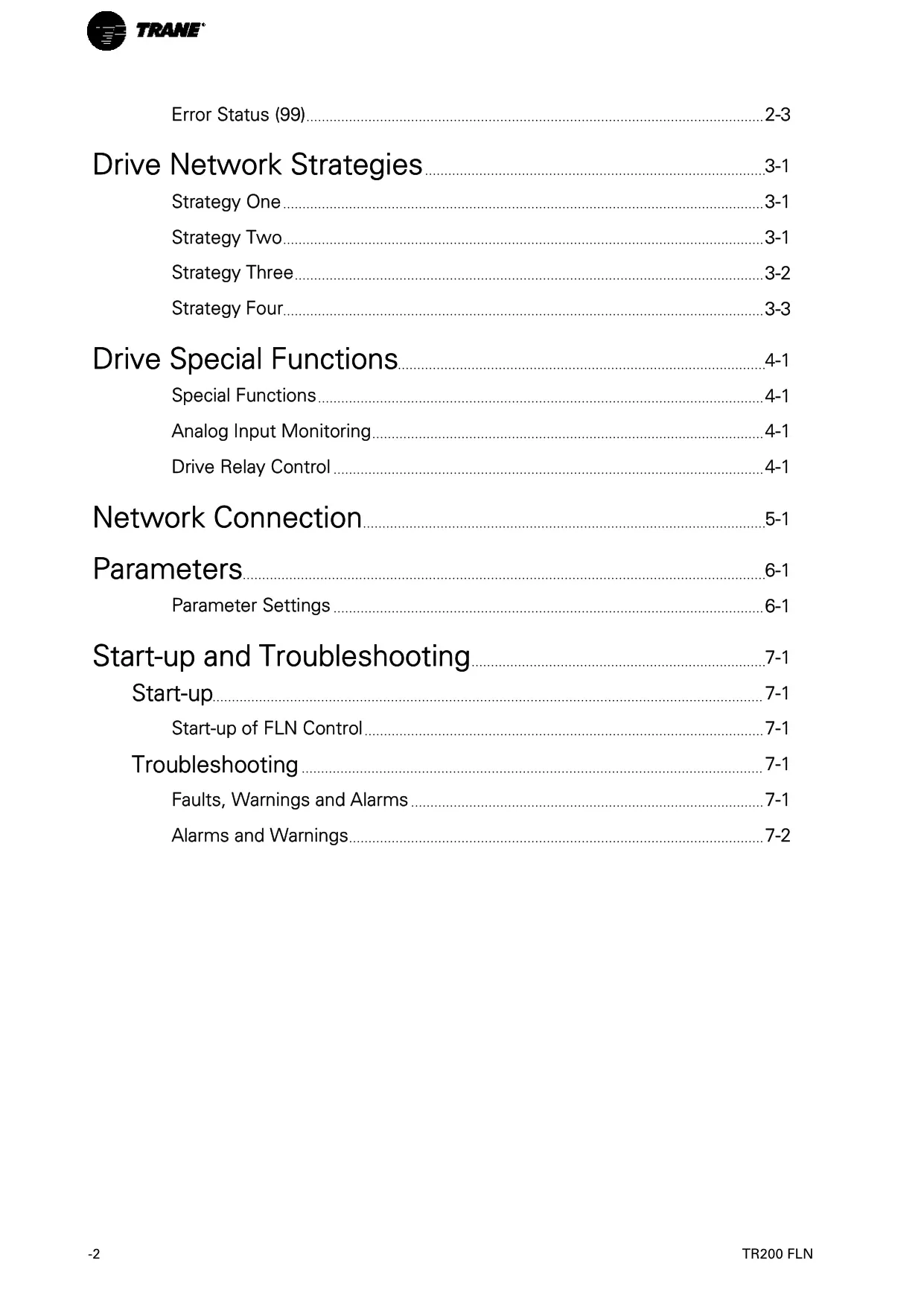
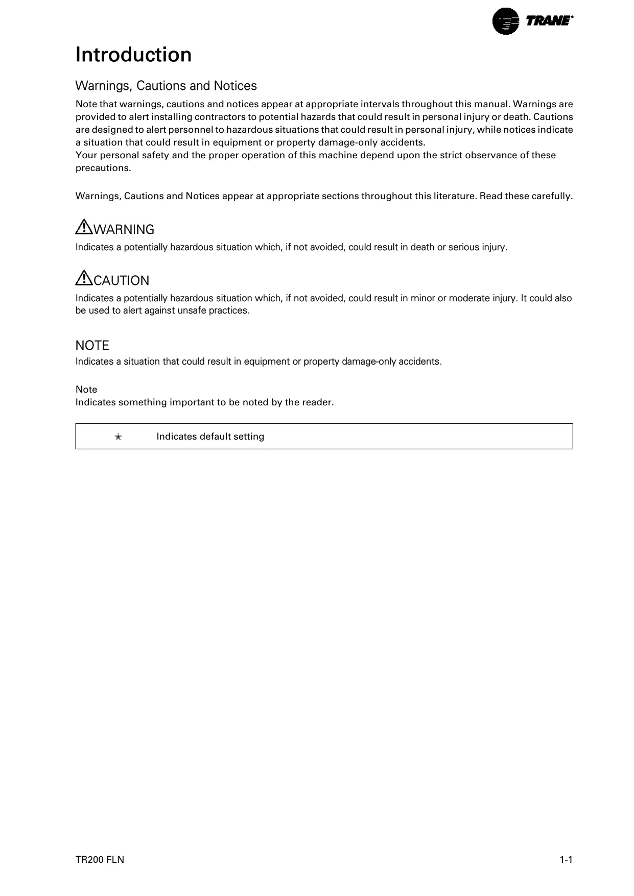









Trane TR200 Variable Frequency Drive
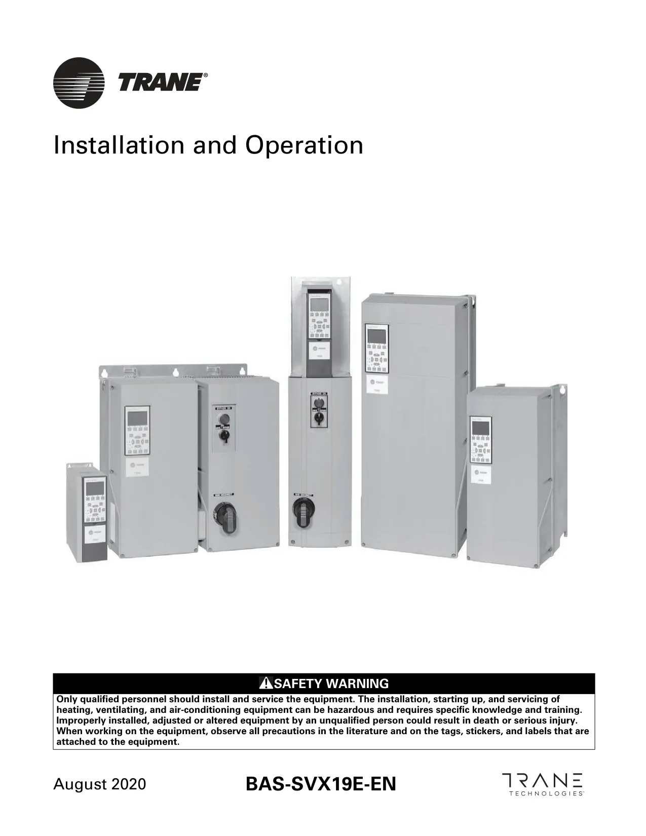
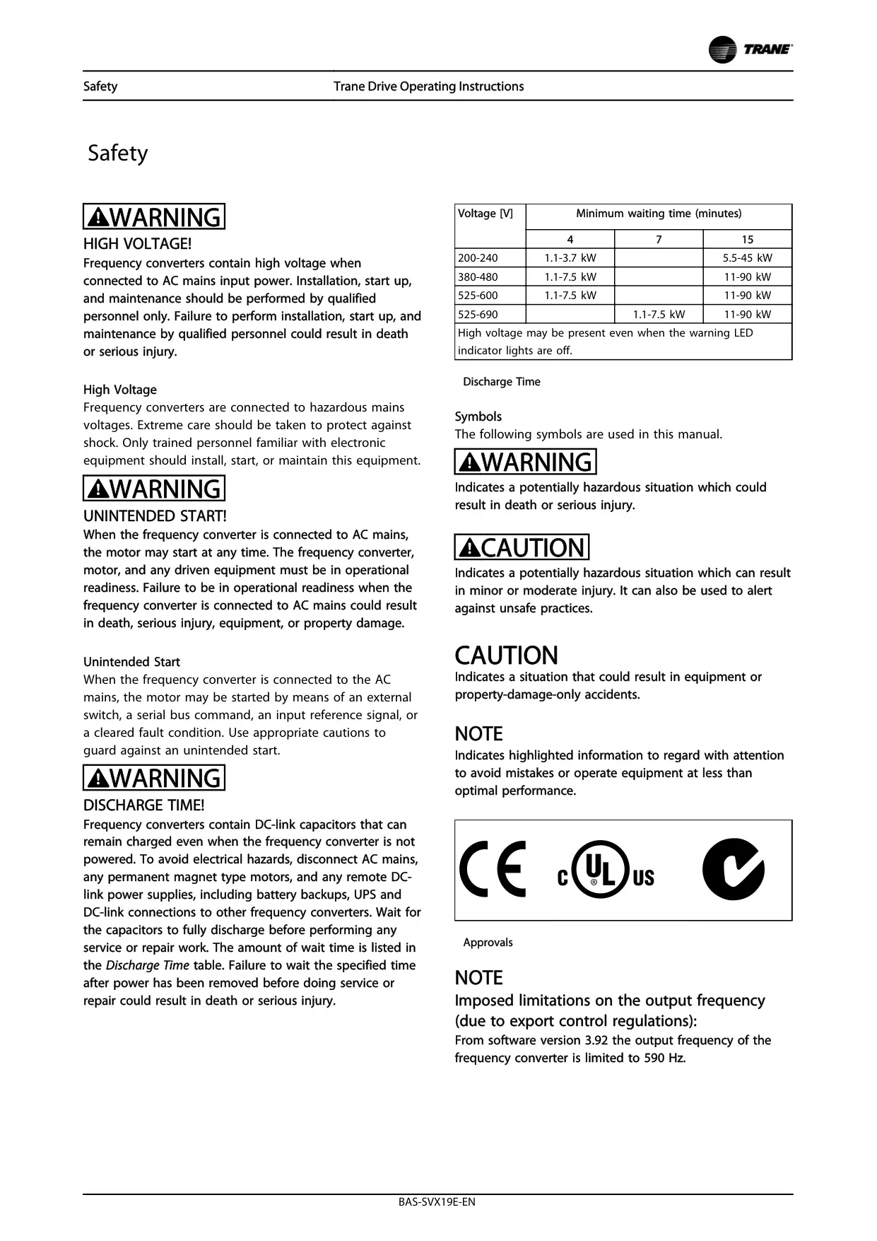


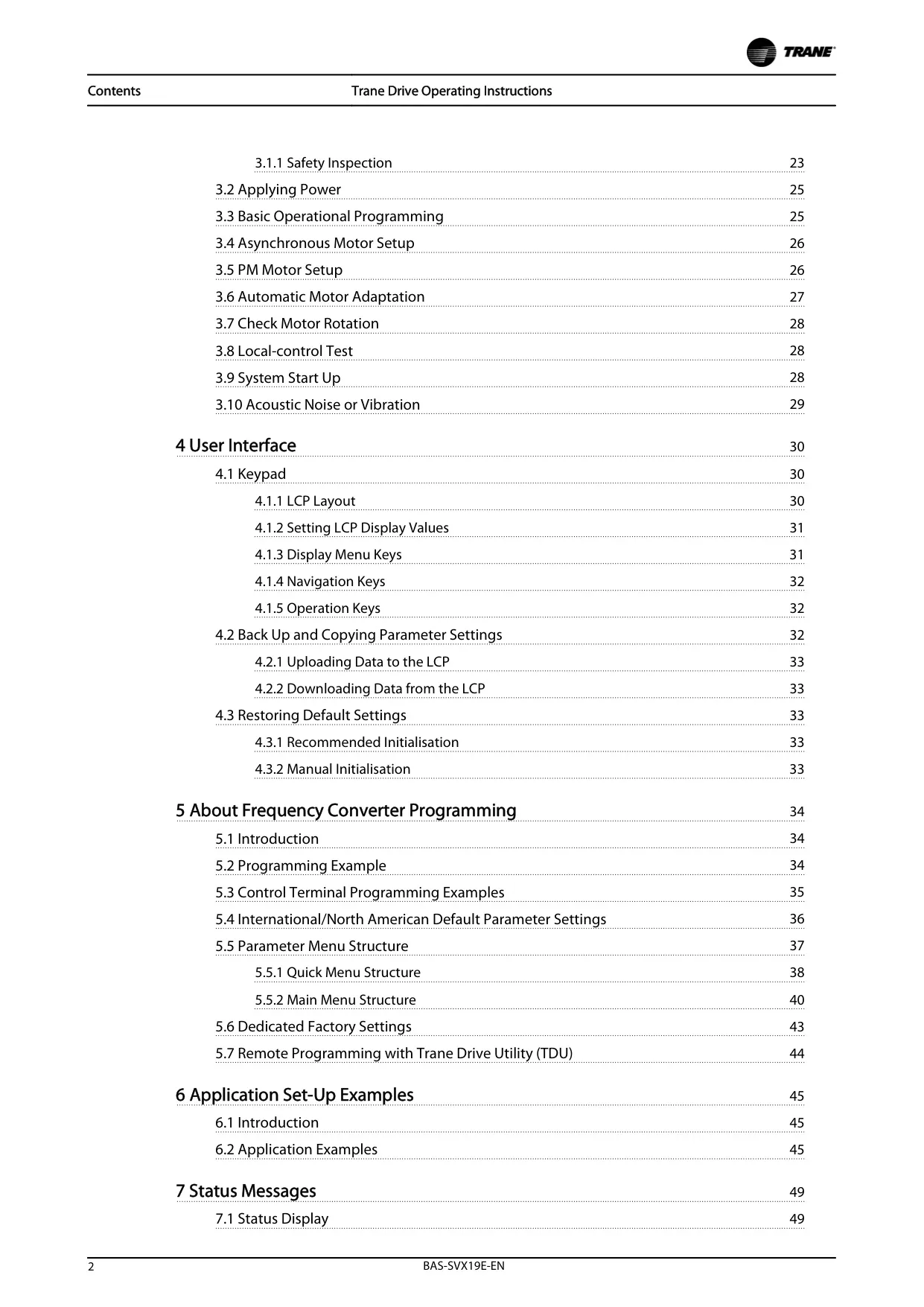
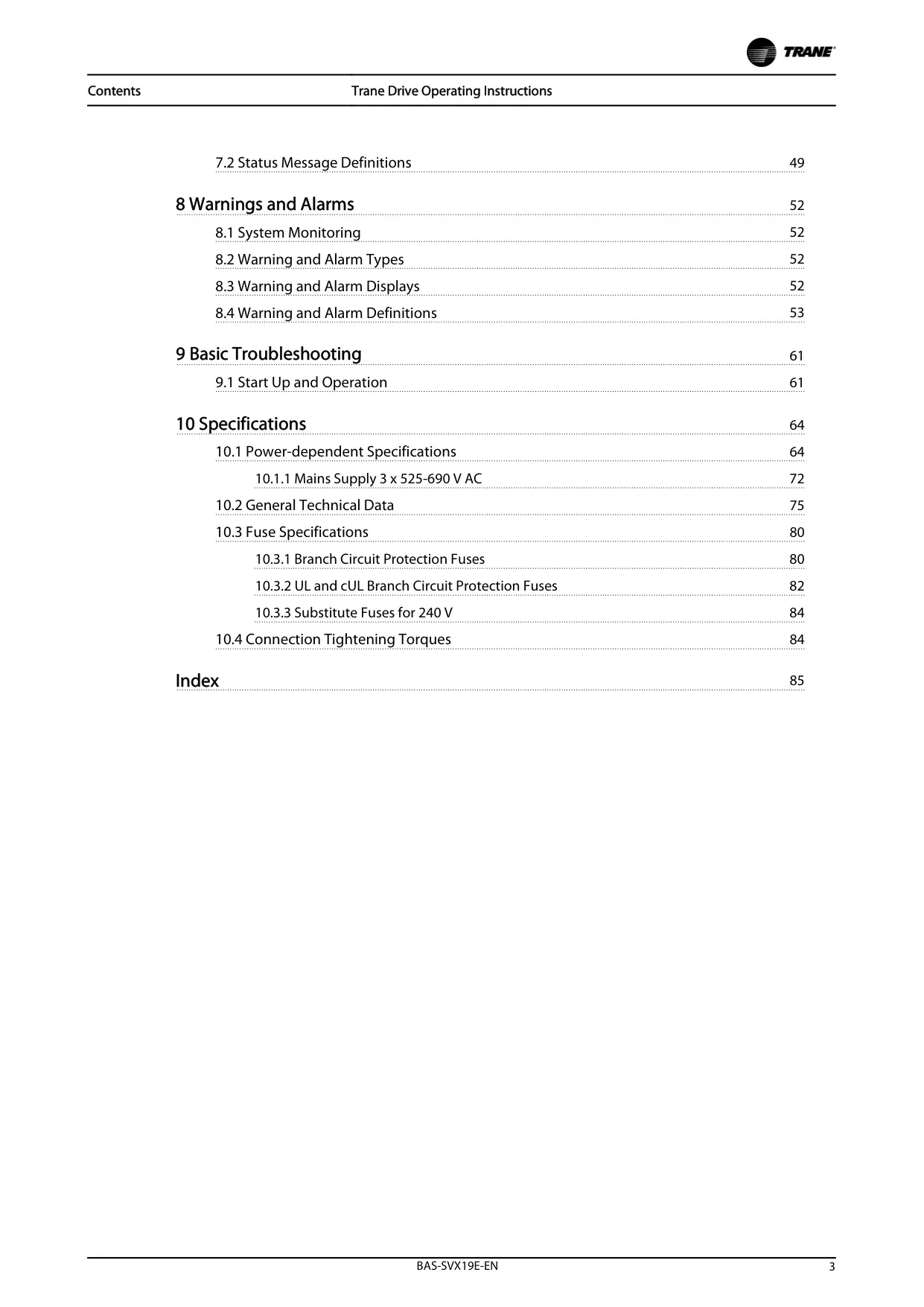



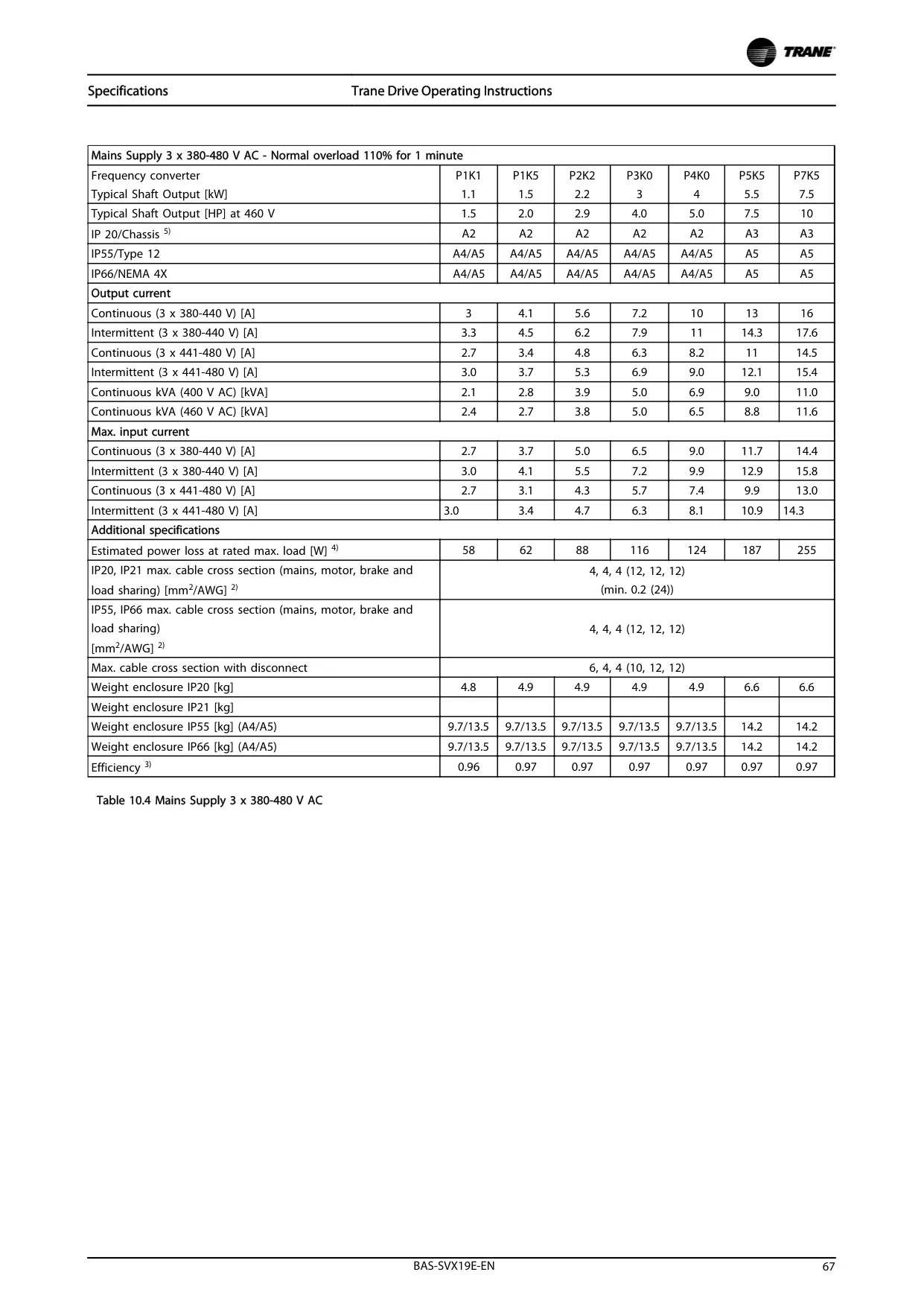
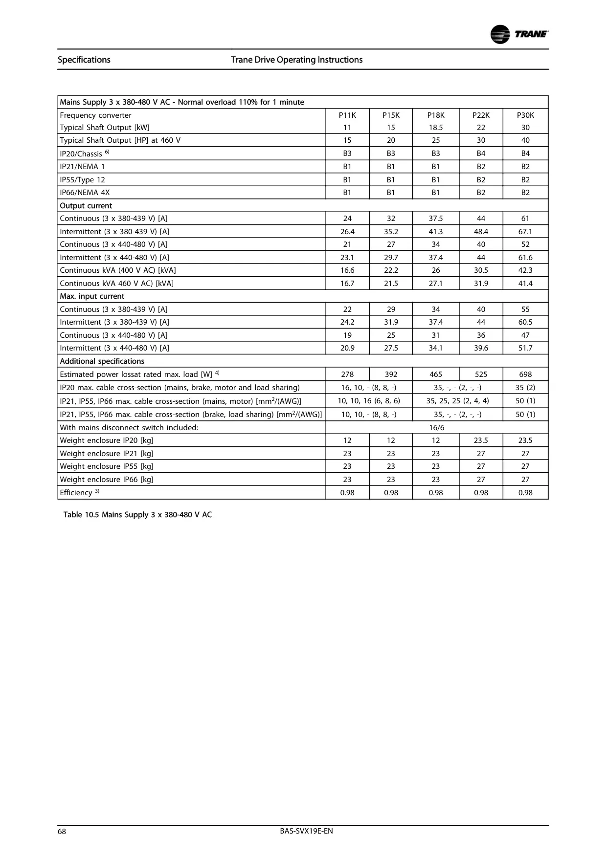
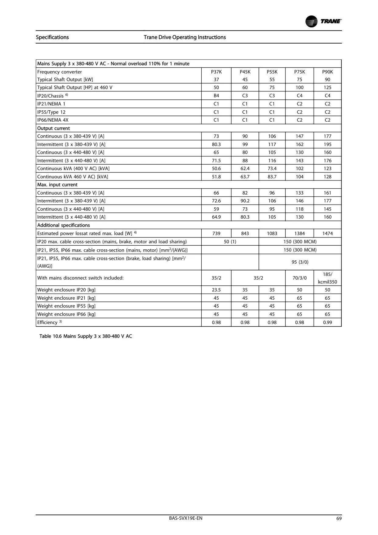
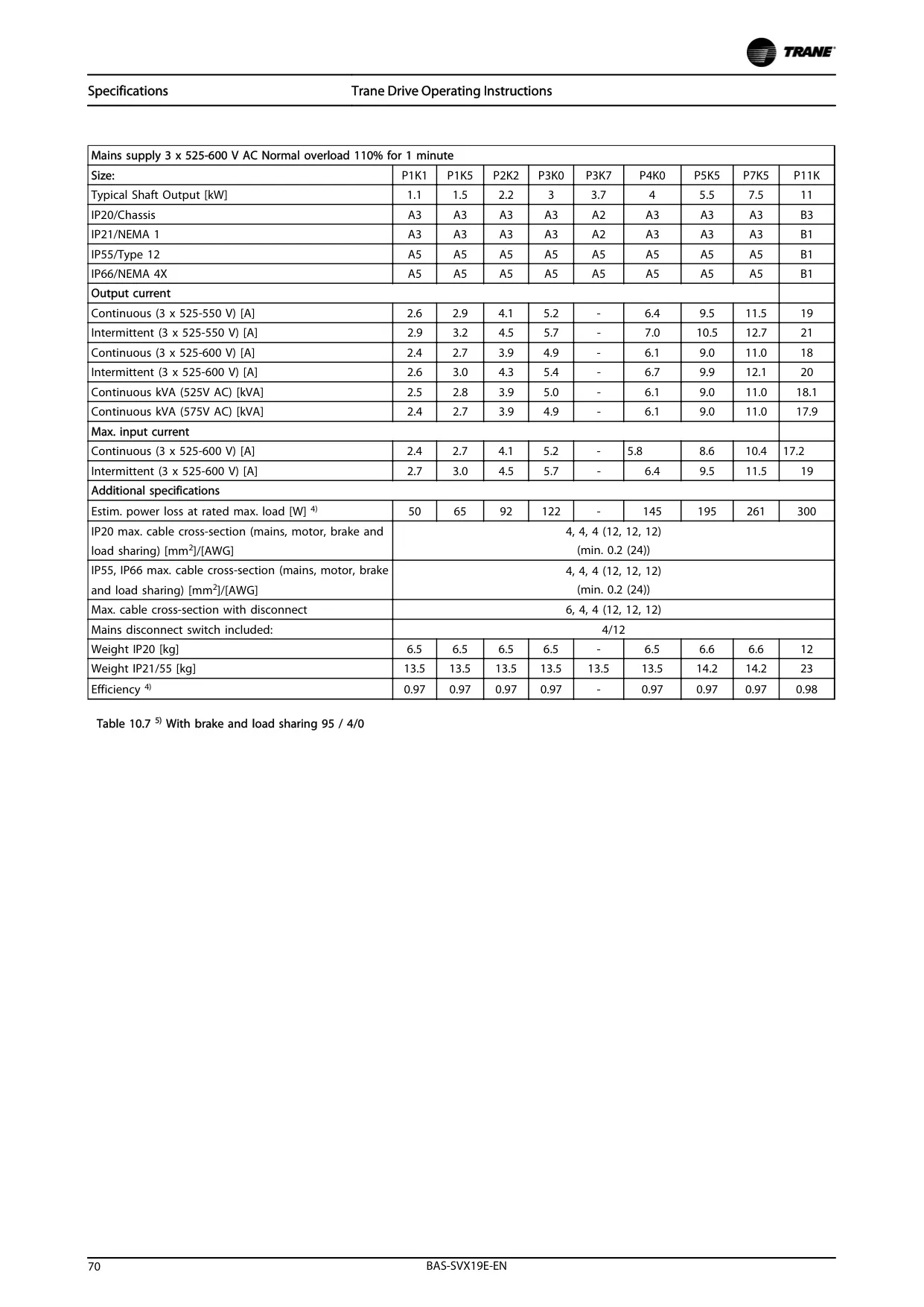

Trane TR200 Variable Frequency Drive
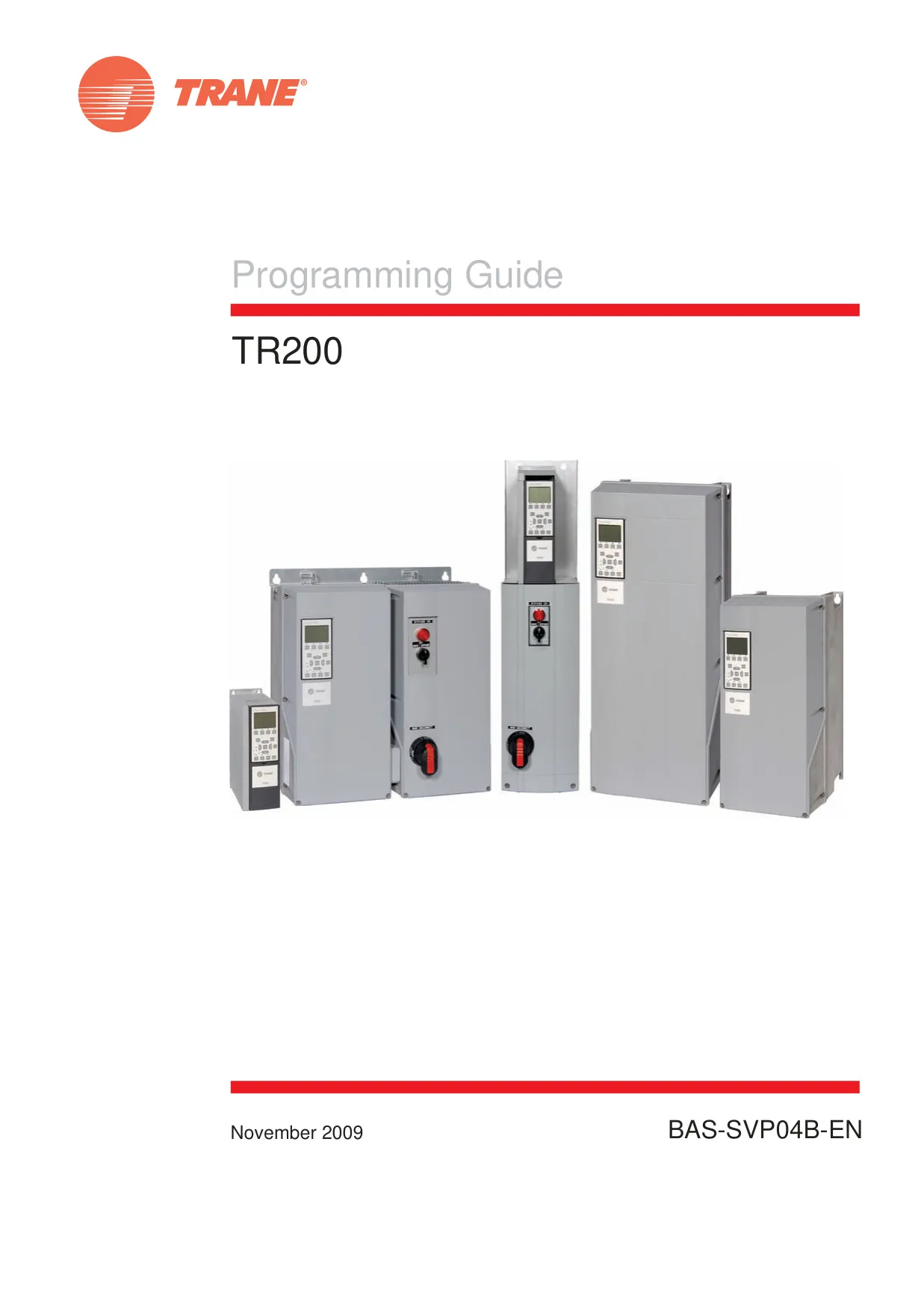
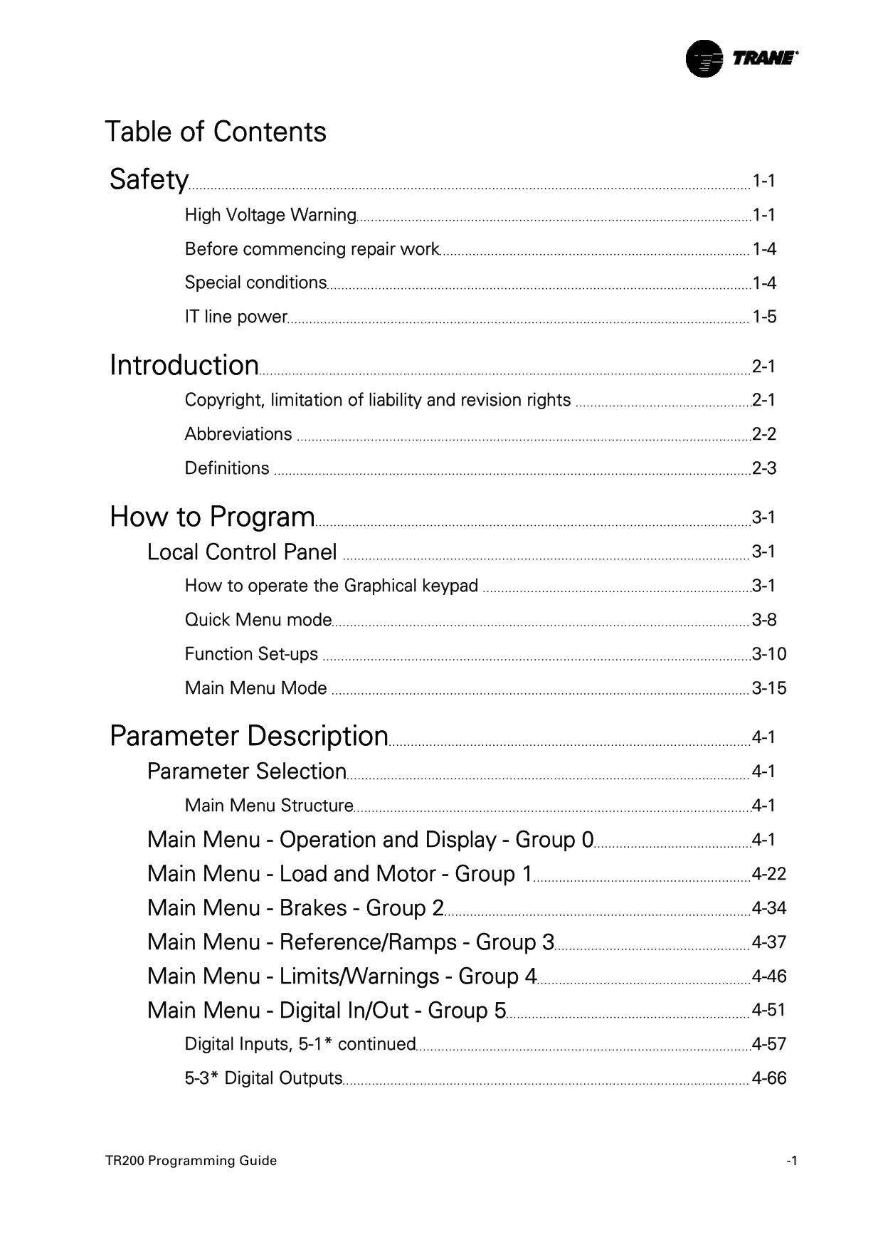
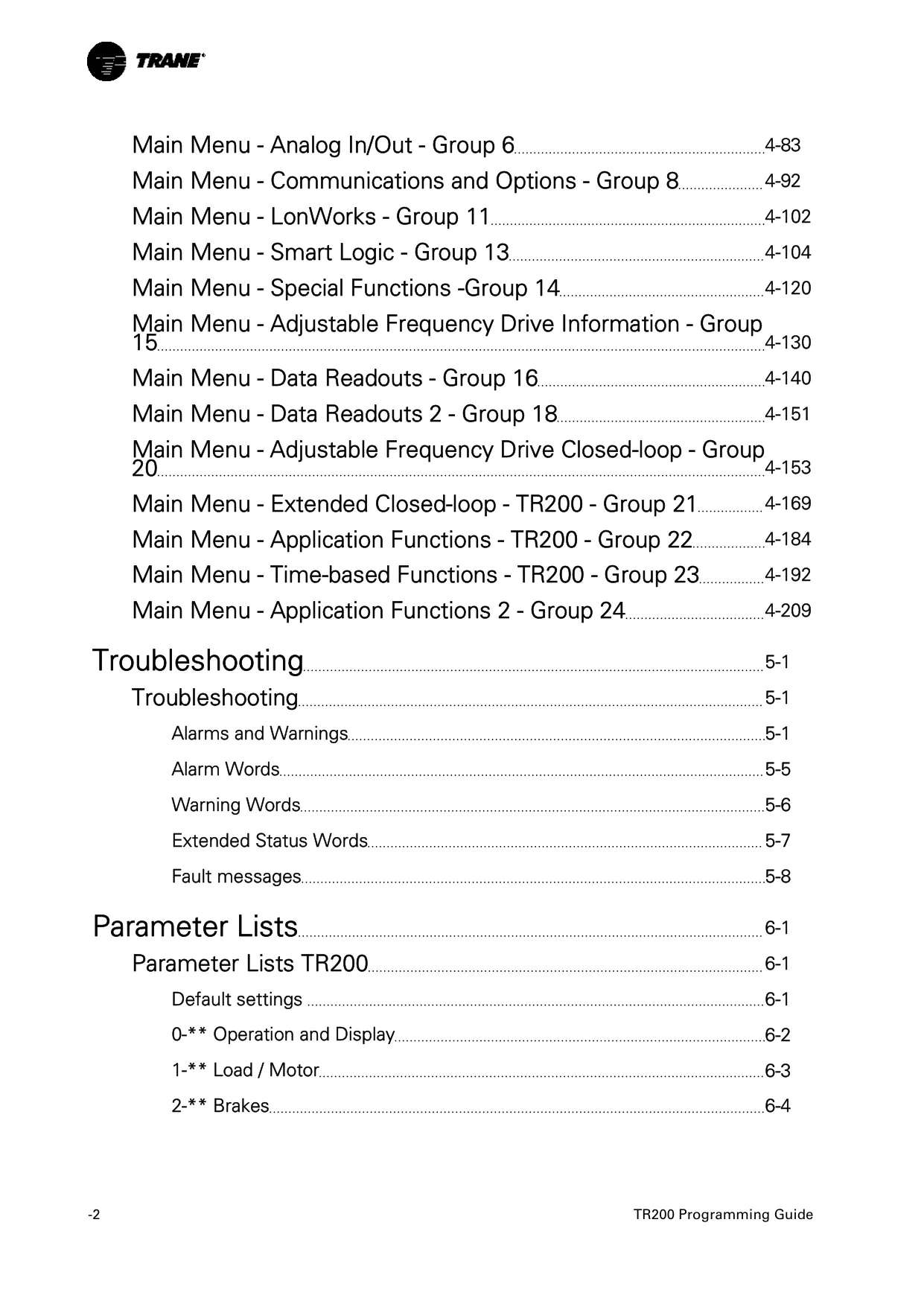
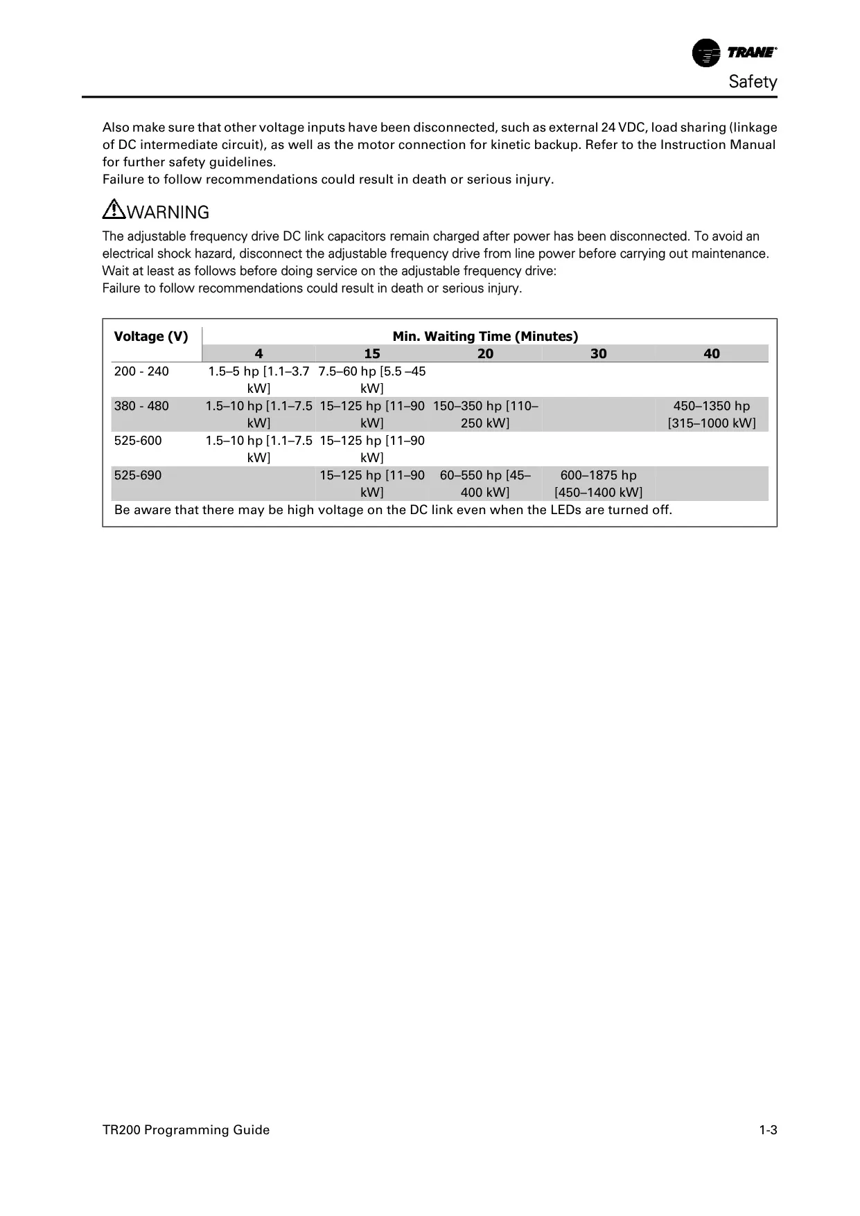
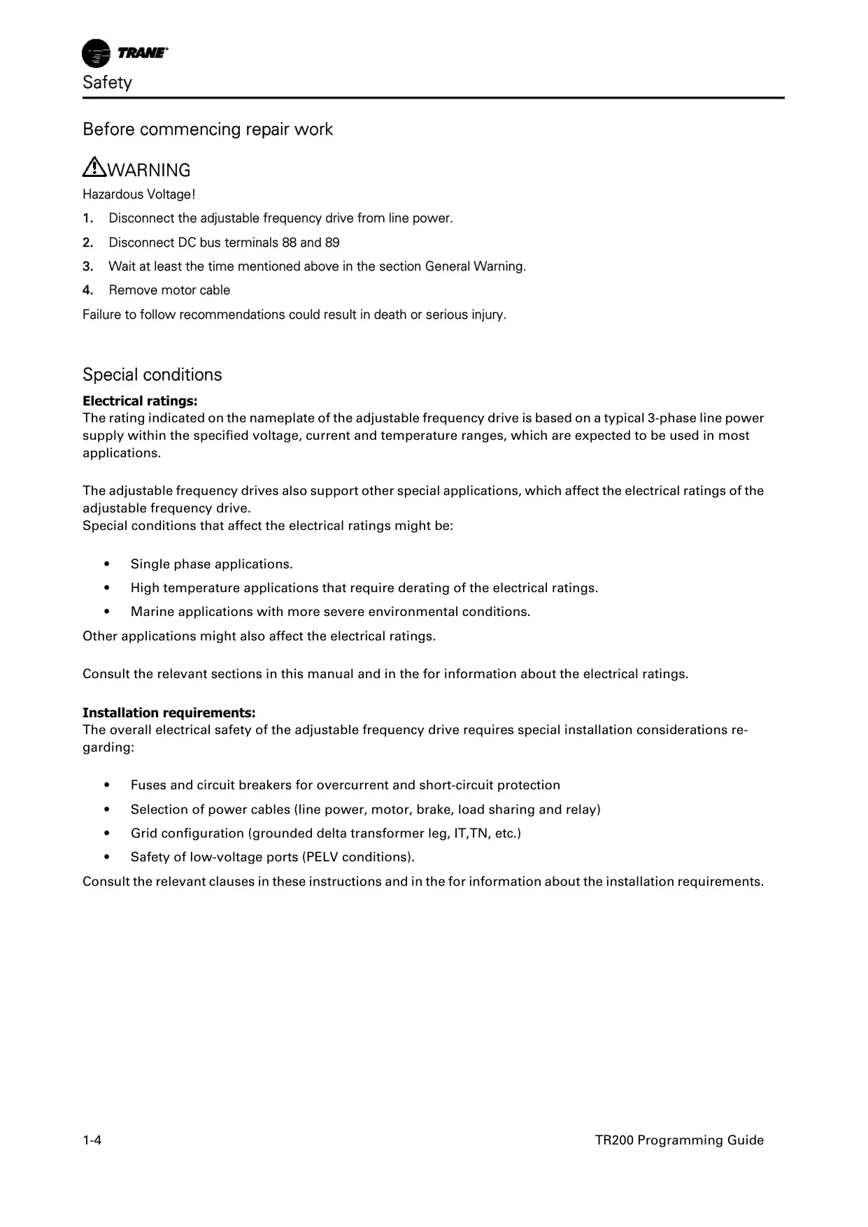
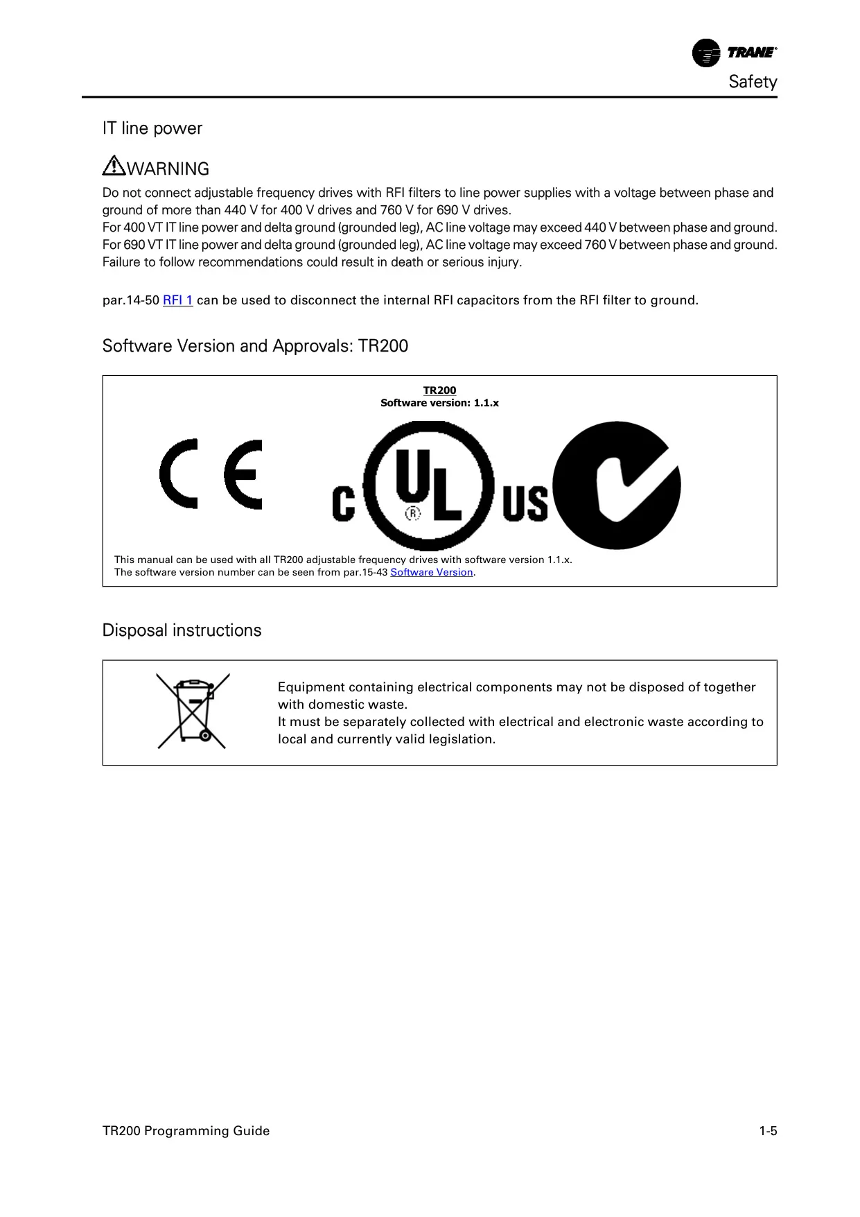
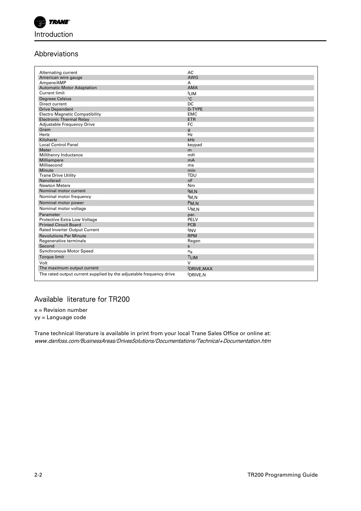
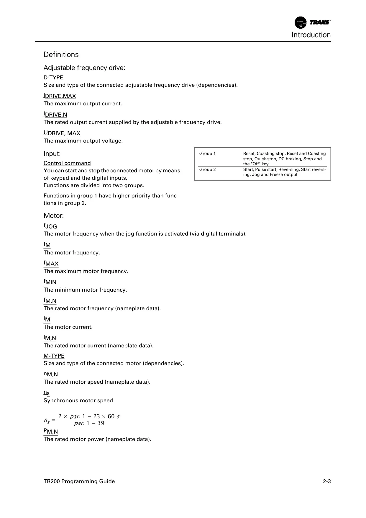
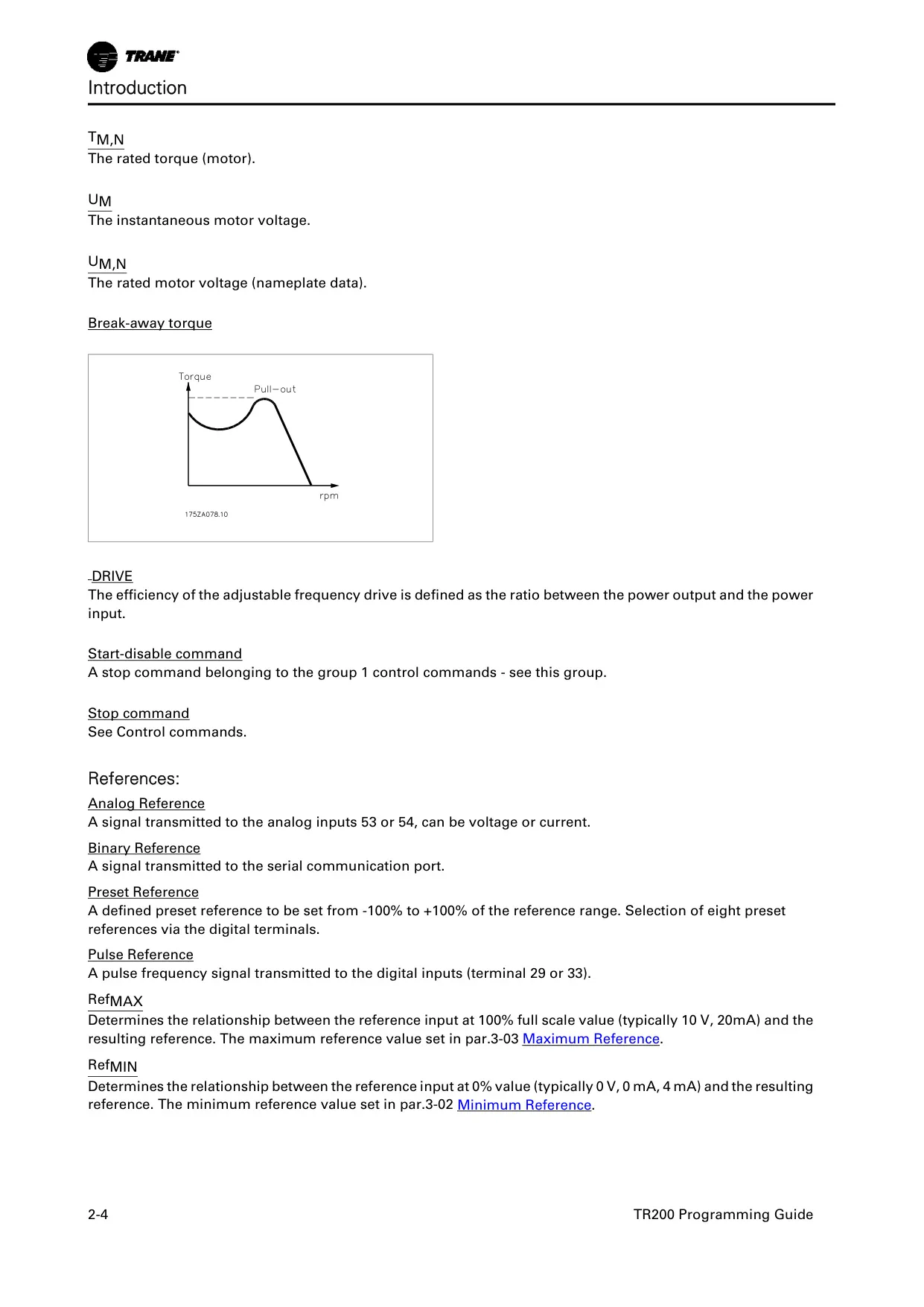
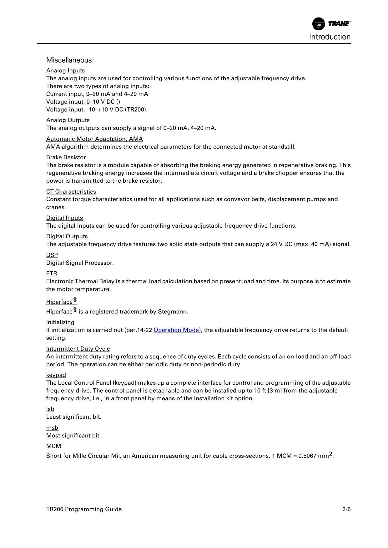
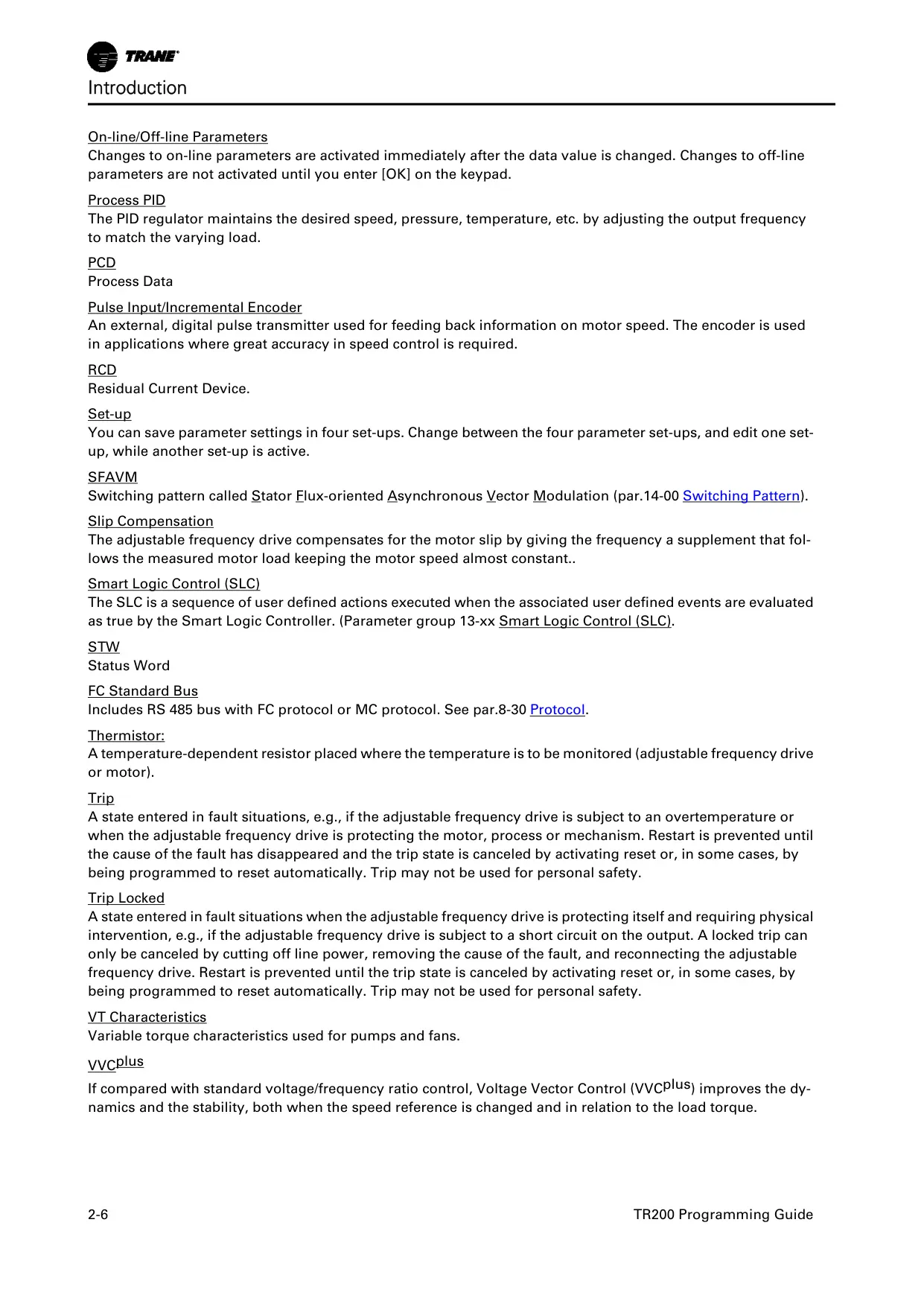
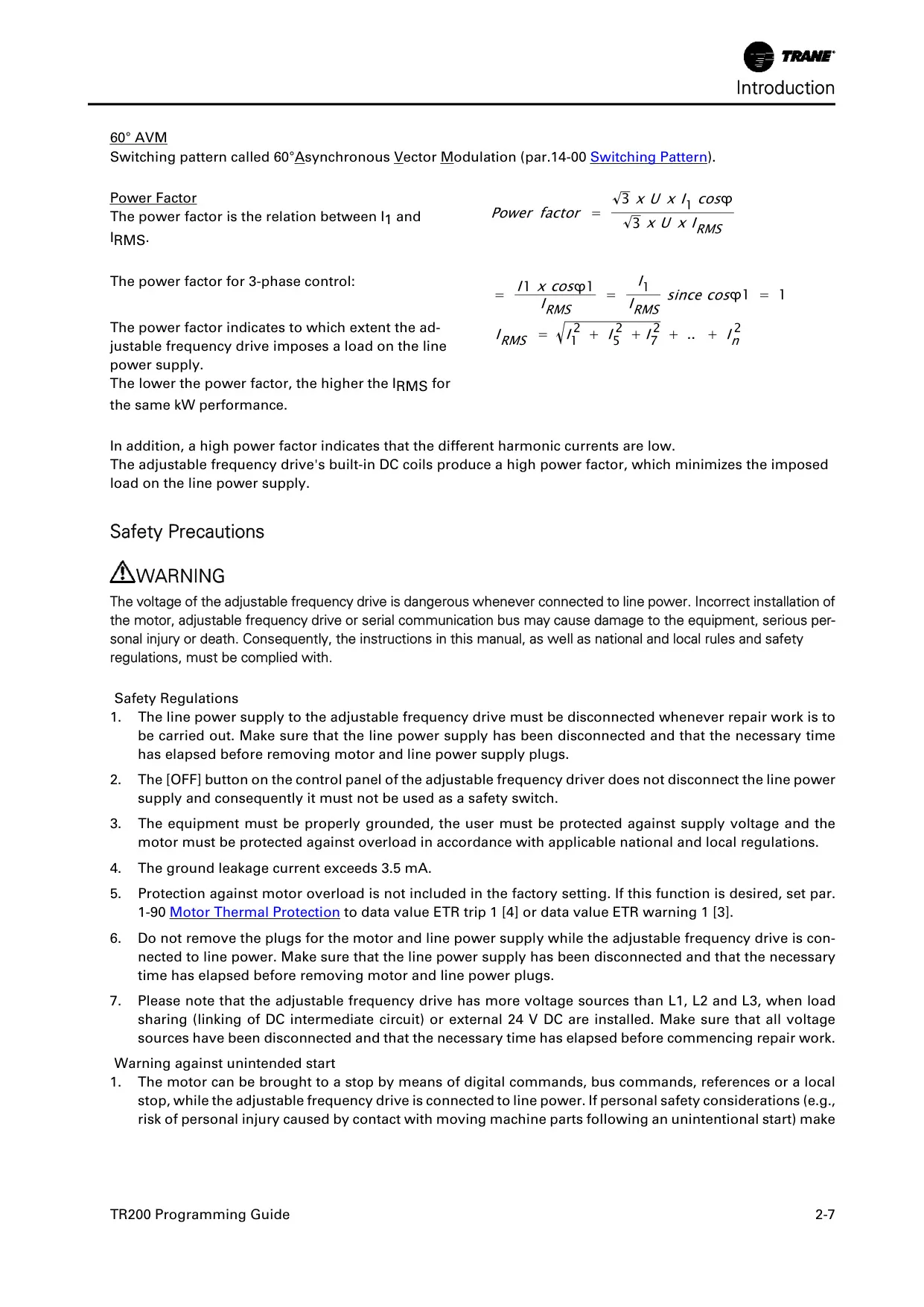
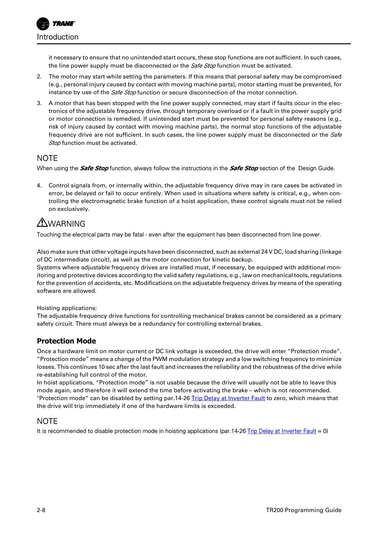
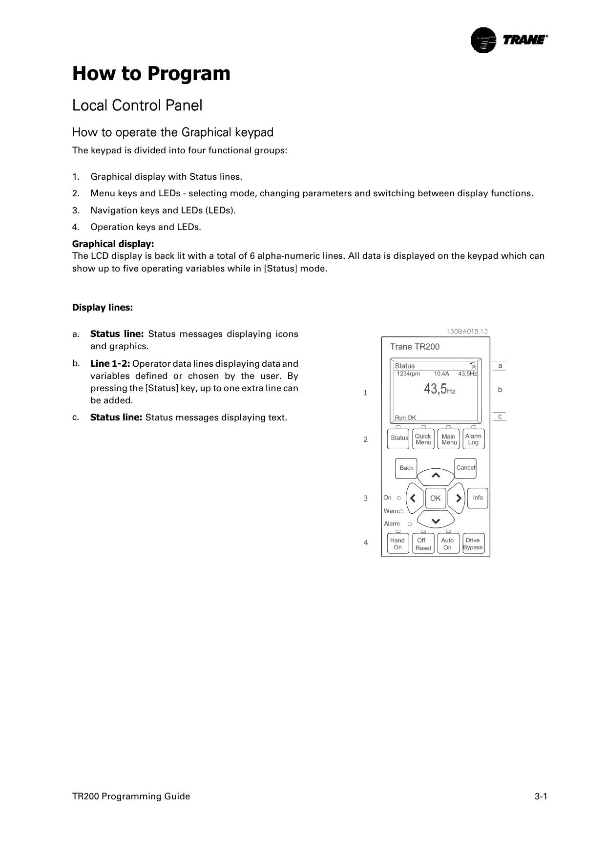
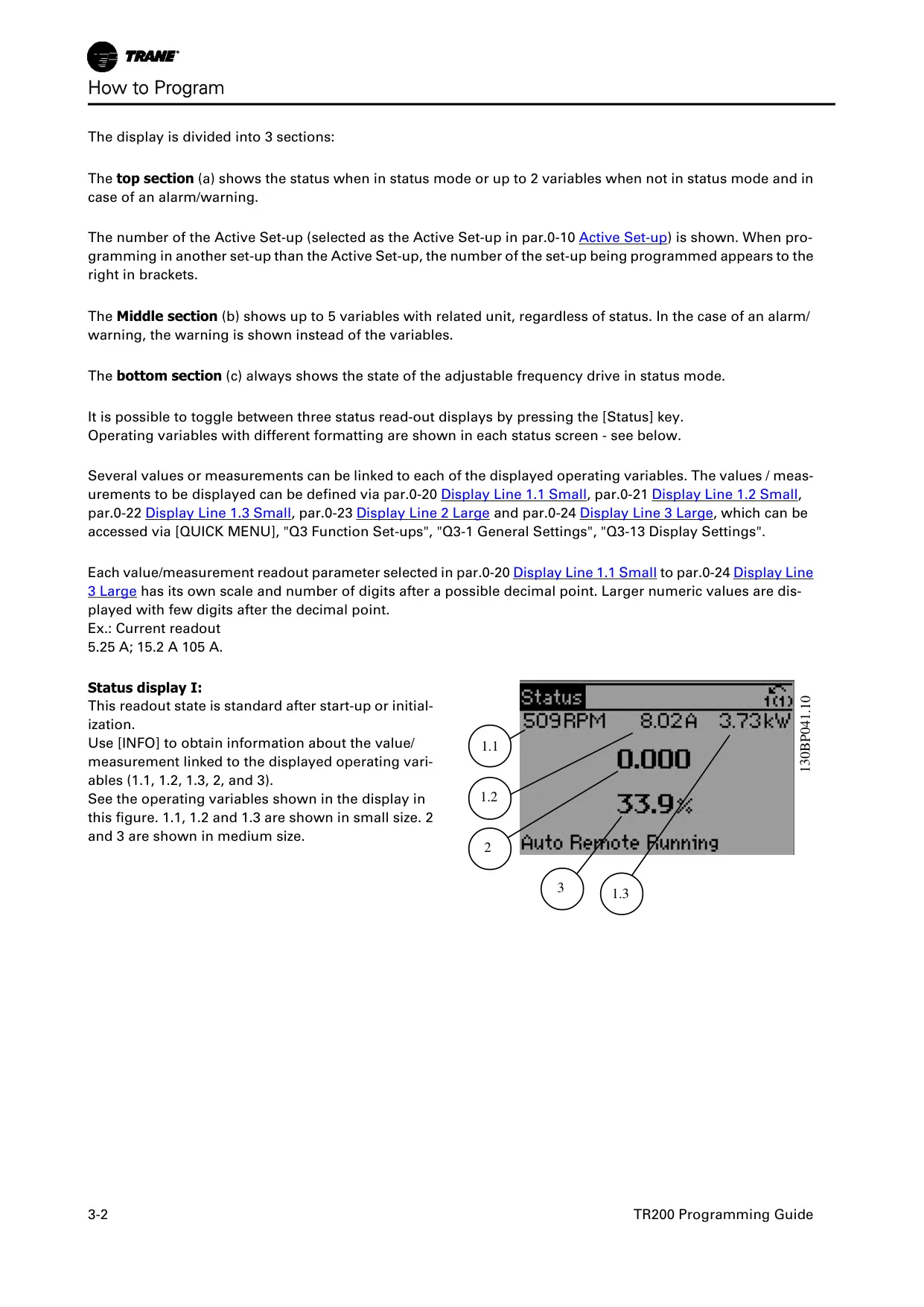
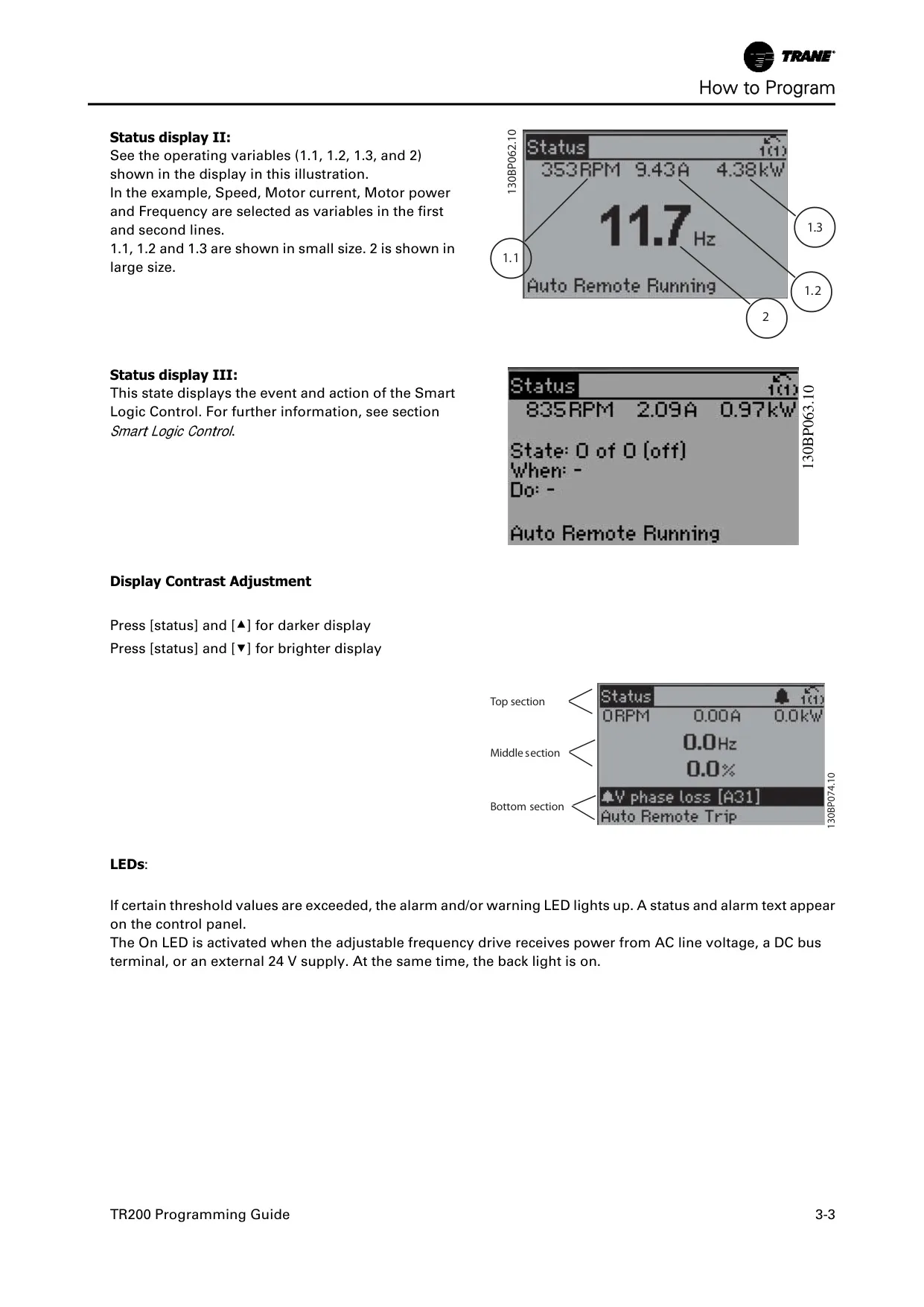
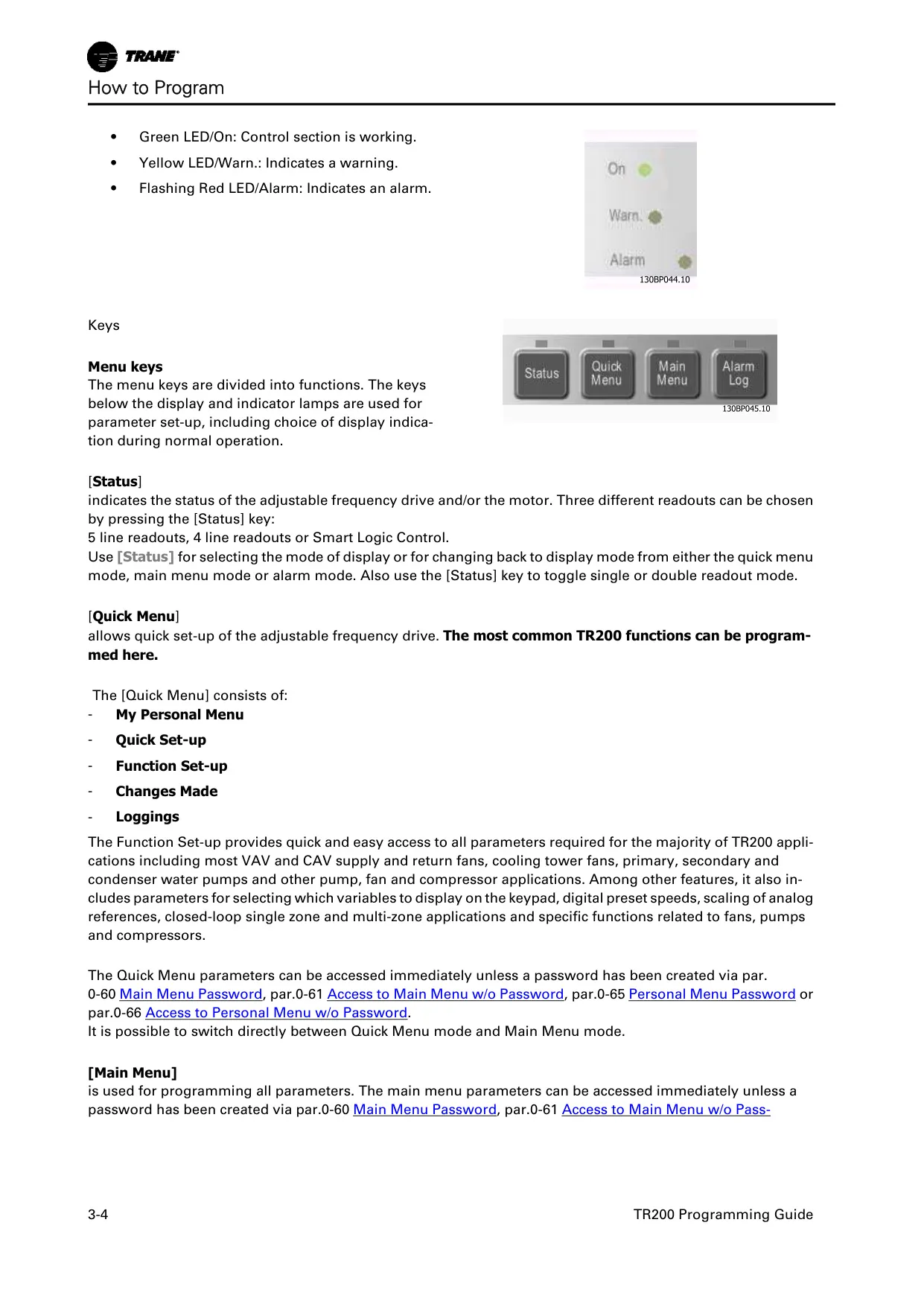
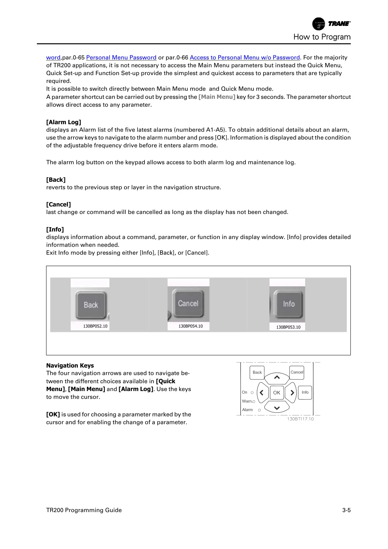
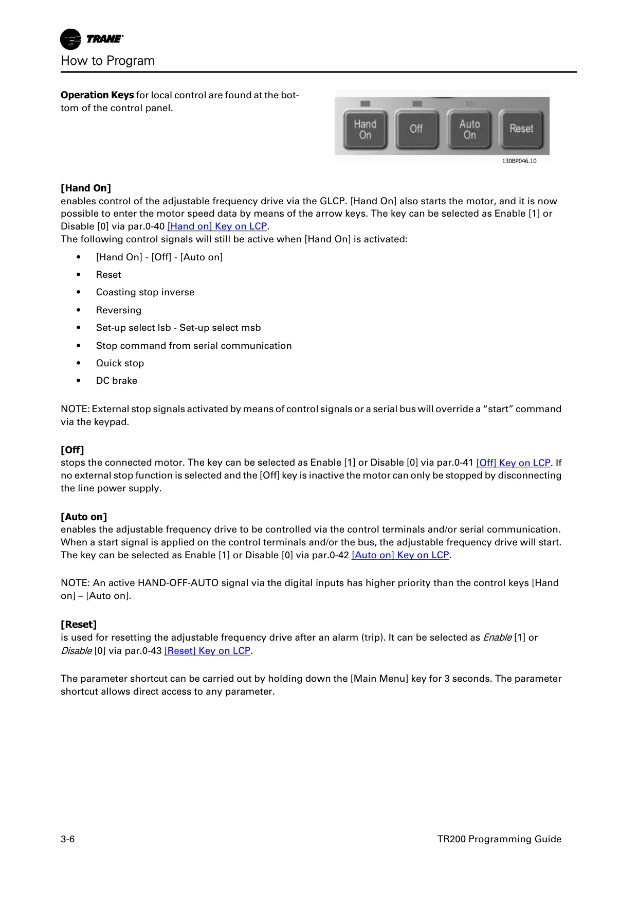
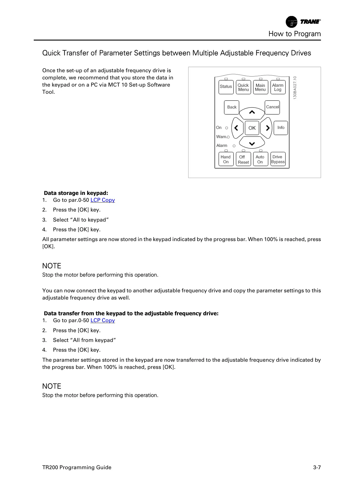
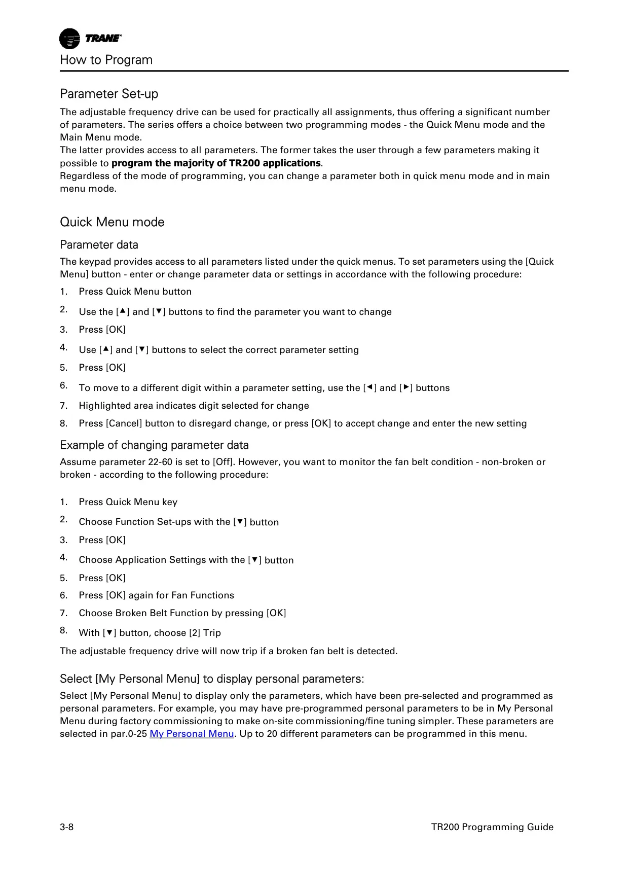
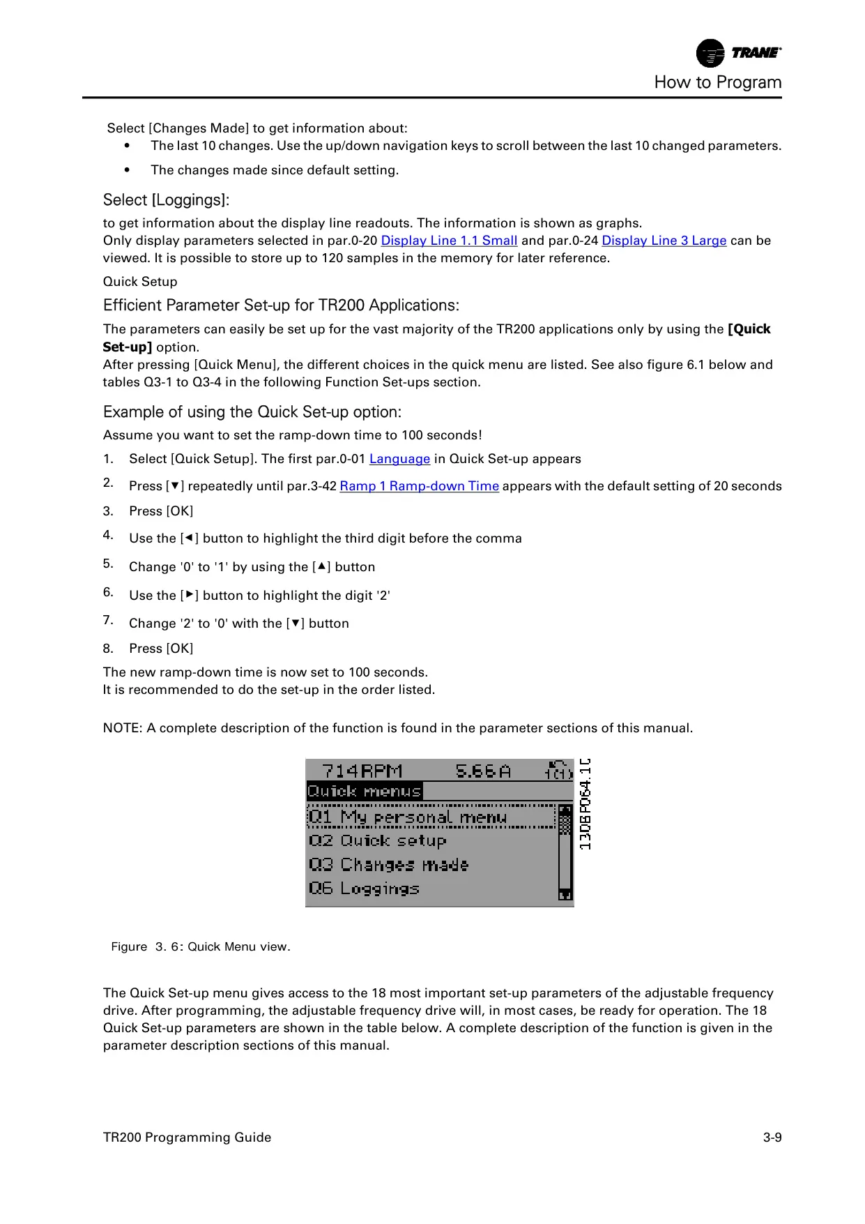
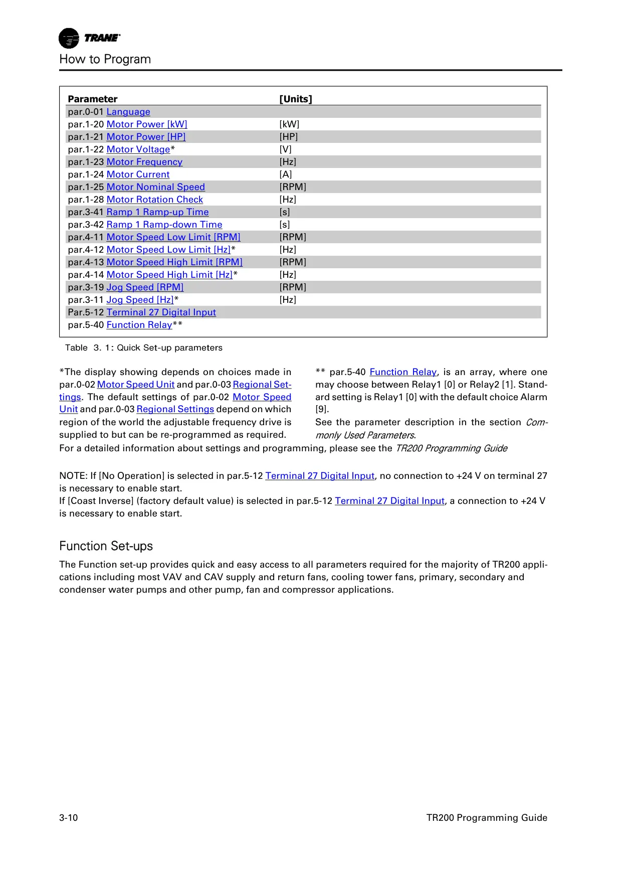
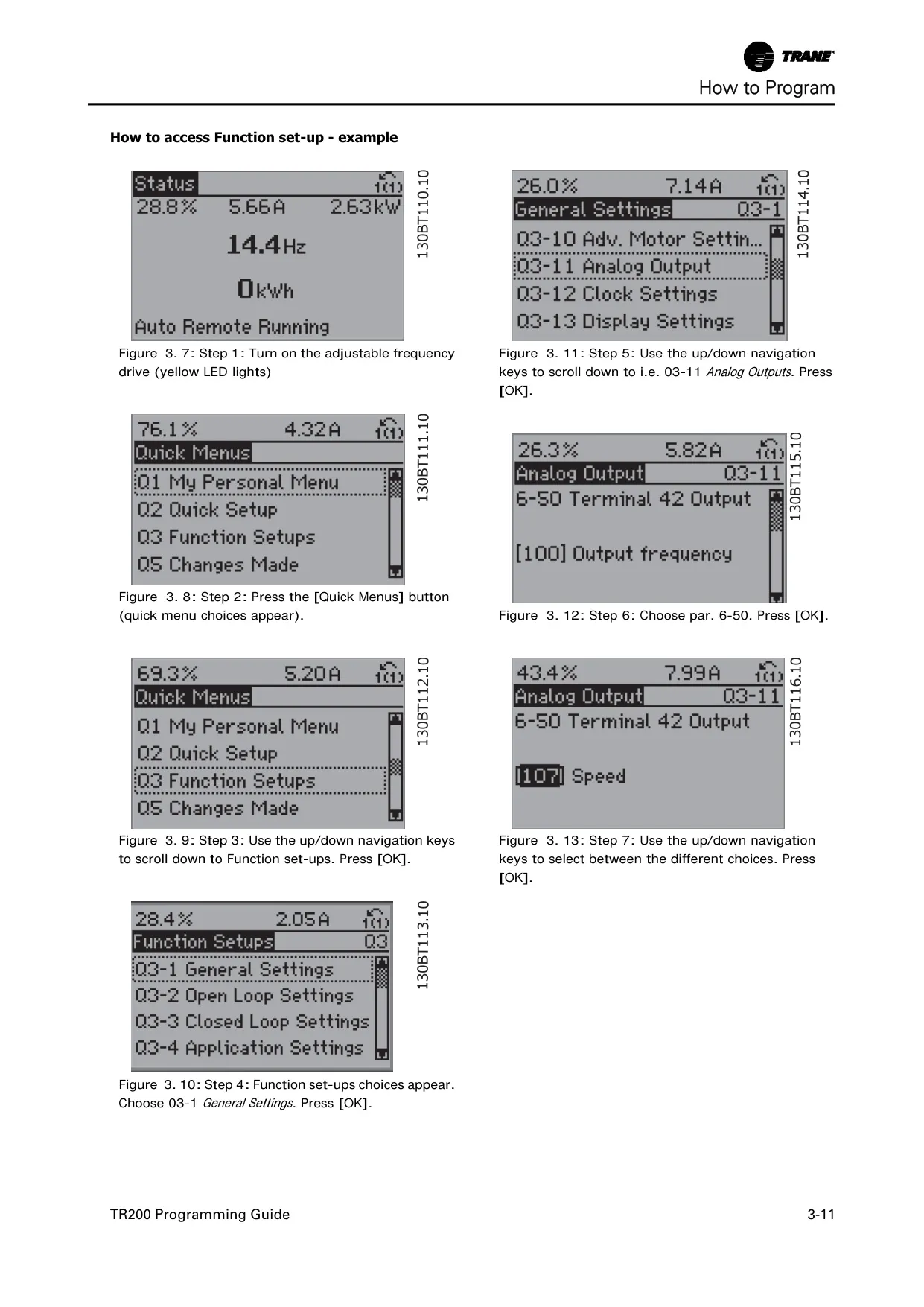
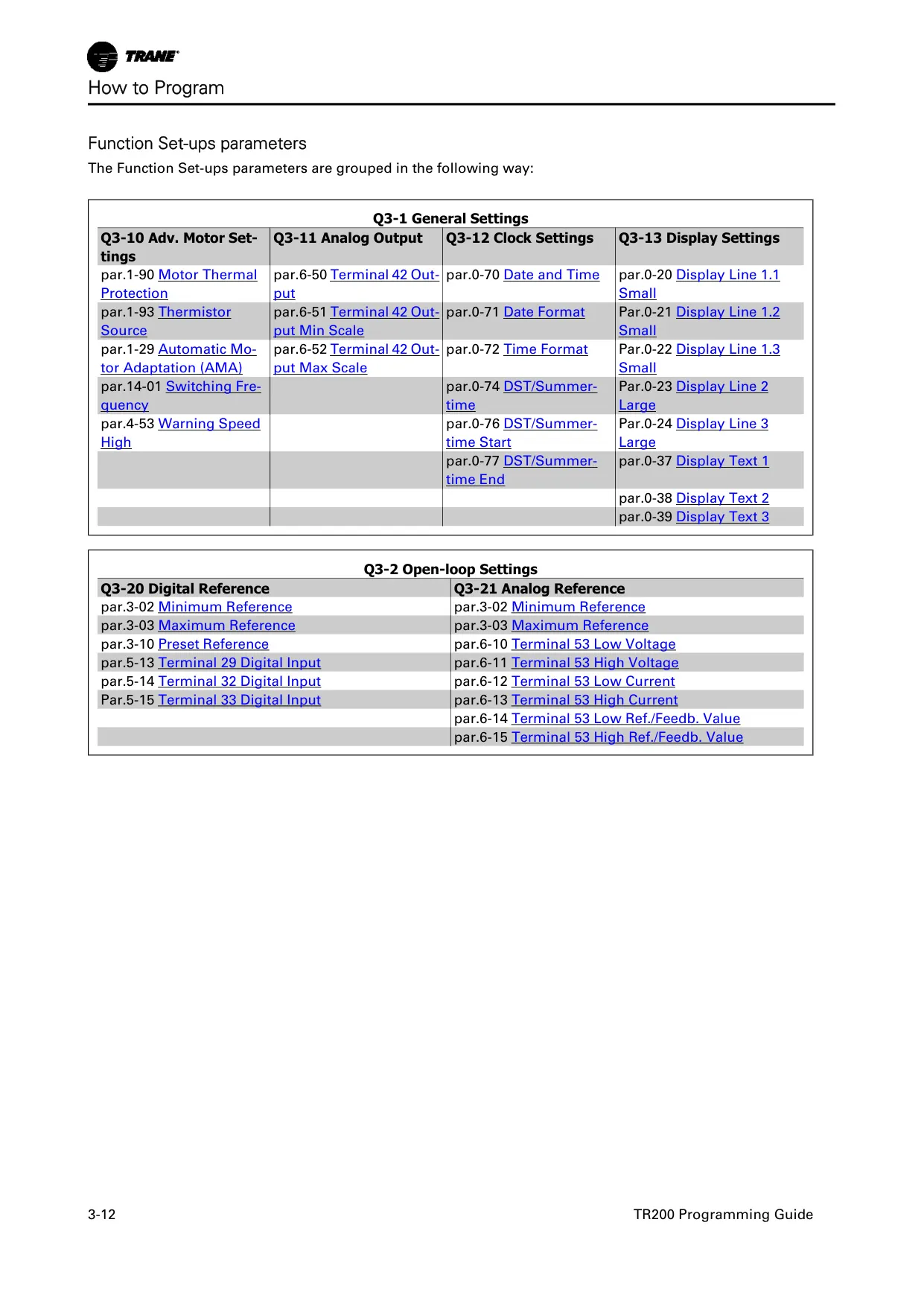
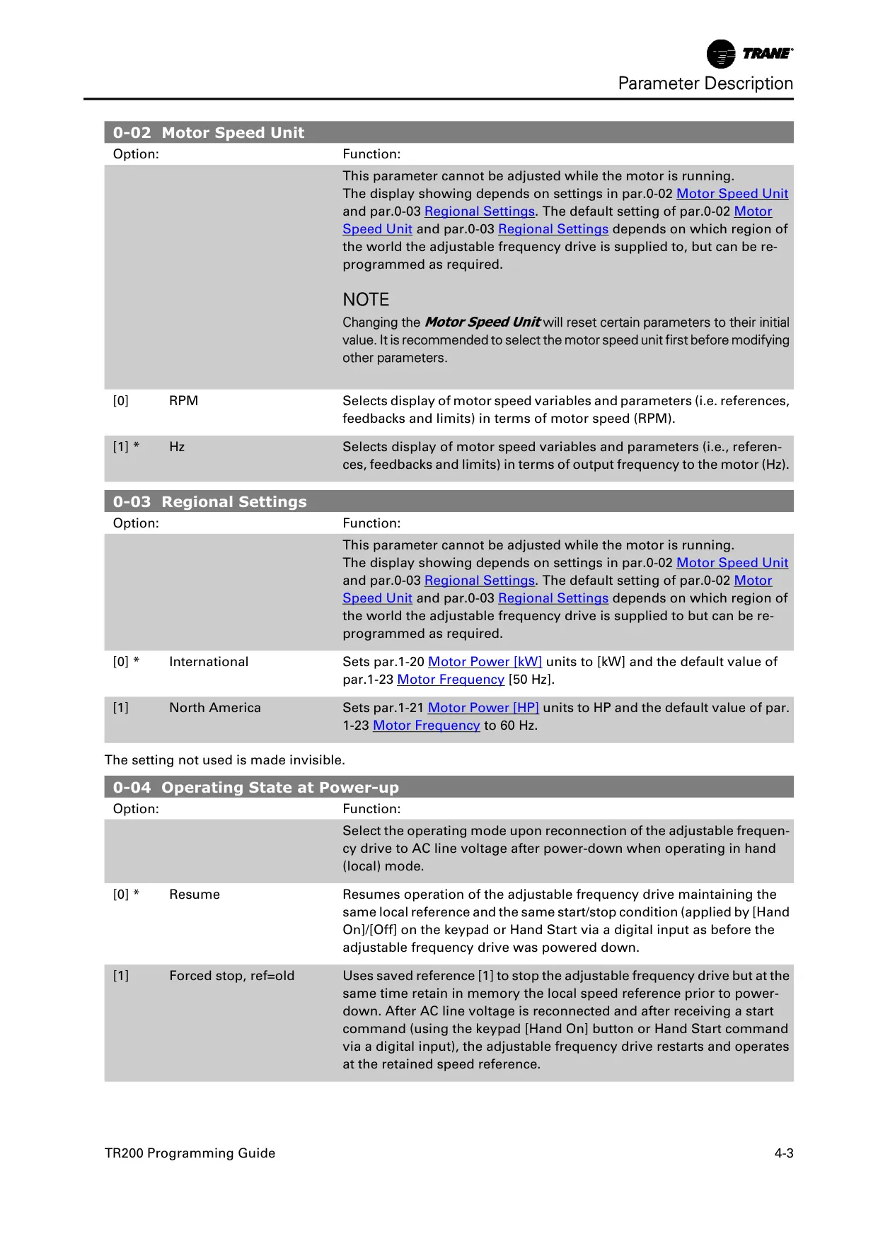
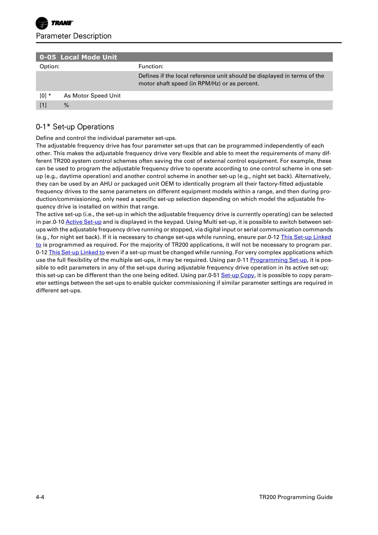
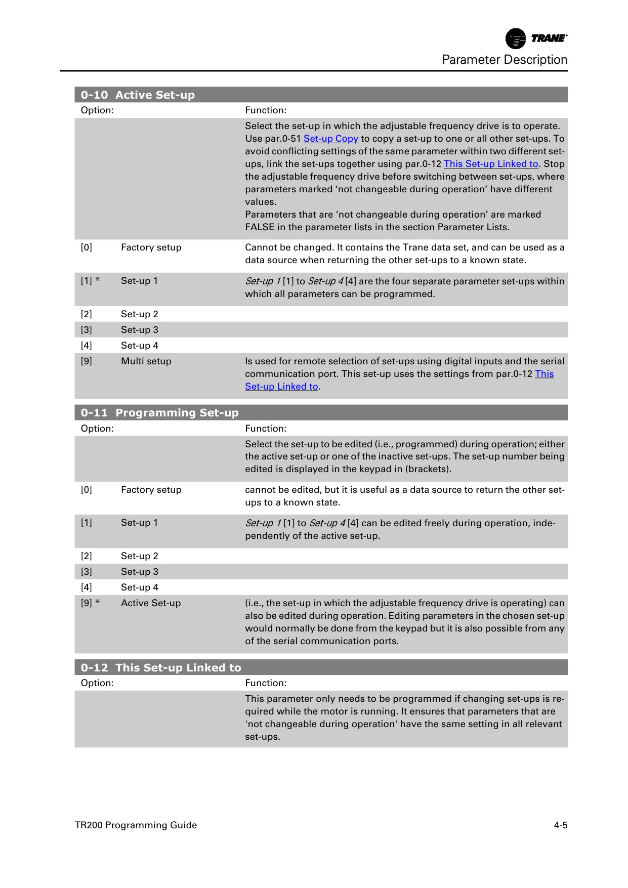
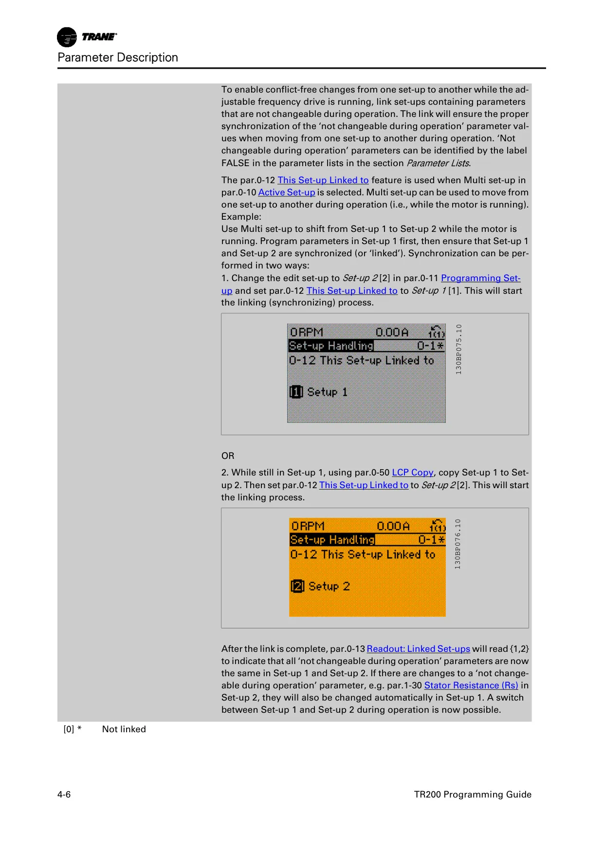
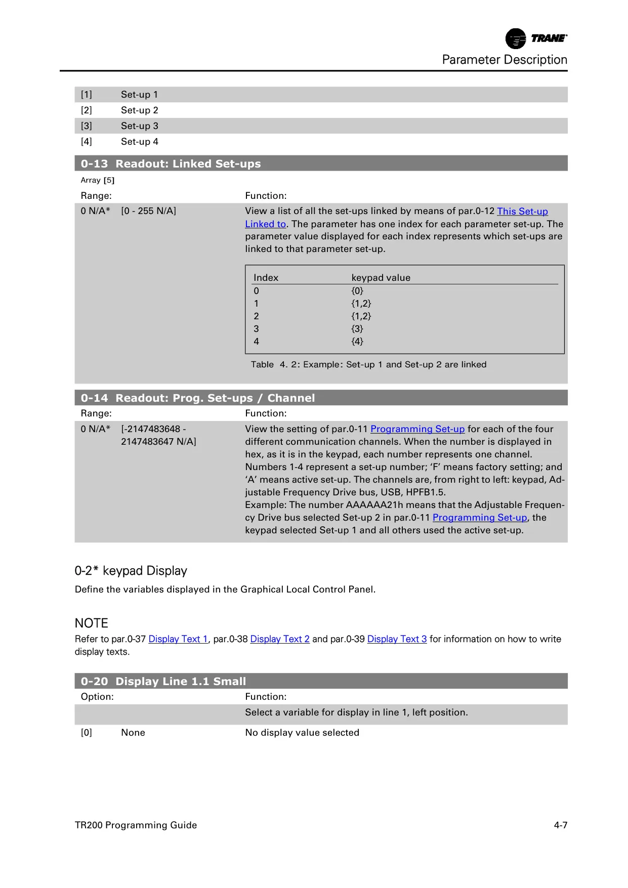
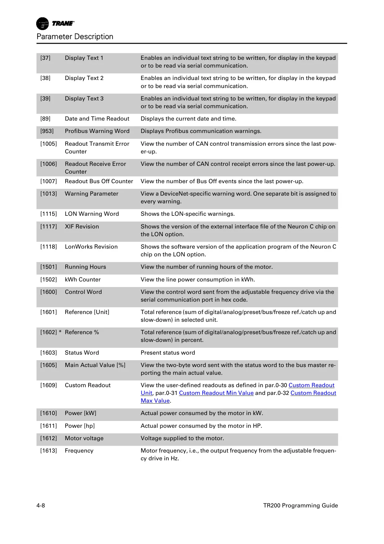
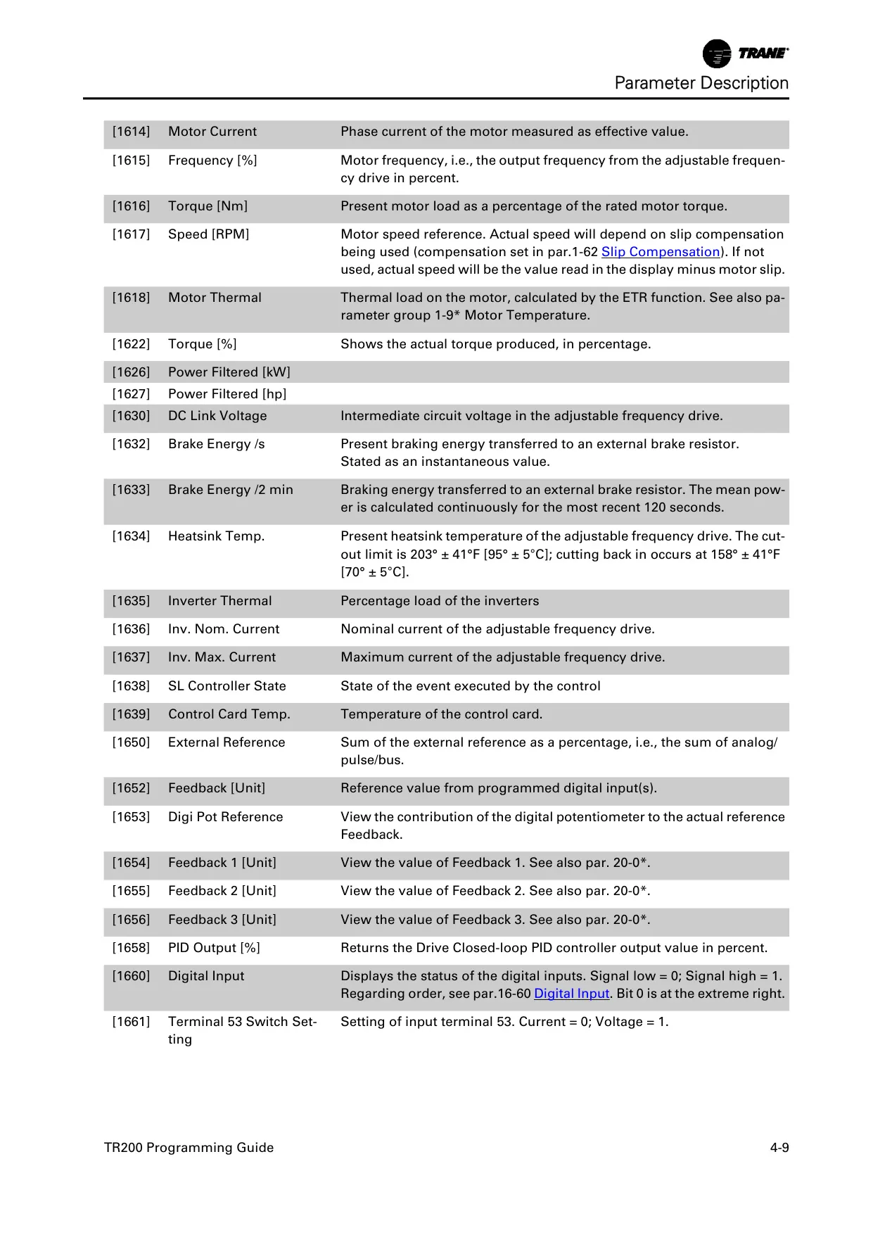
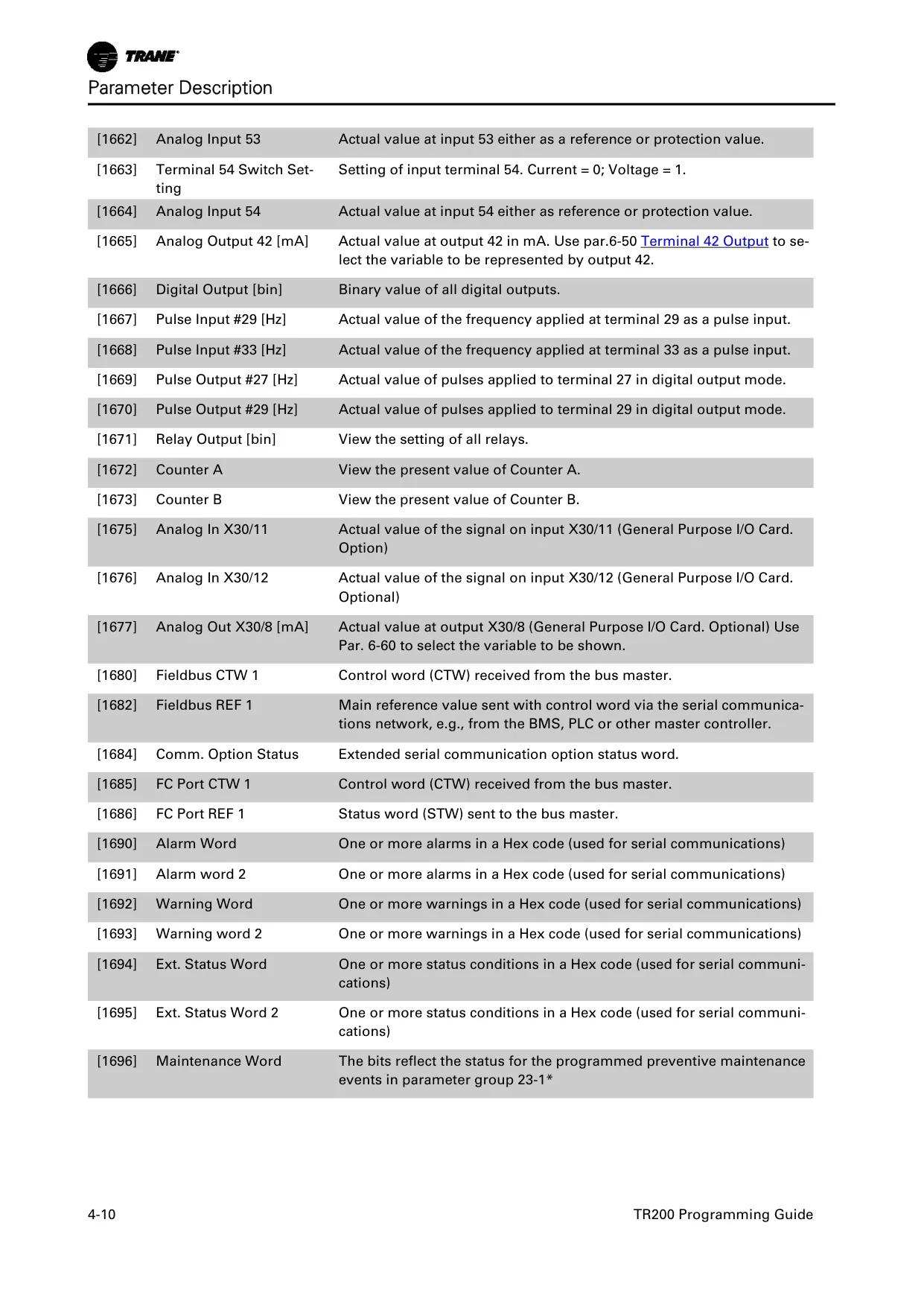
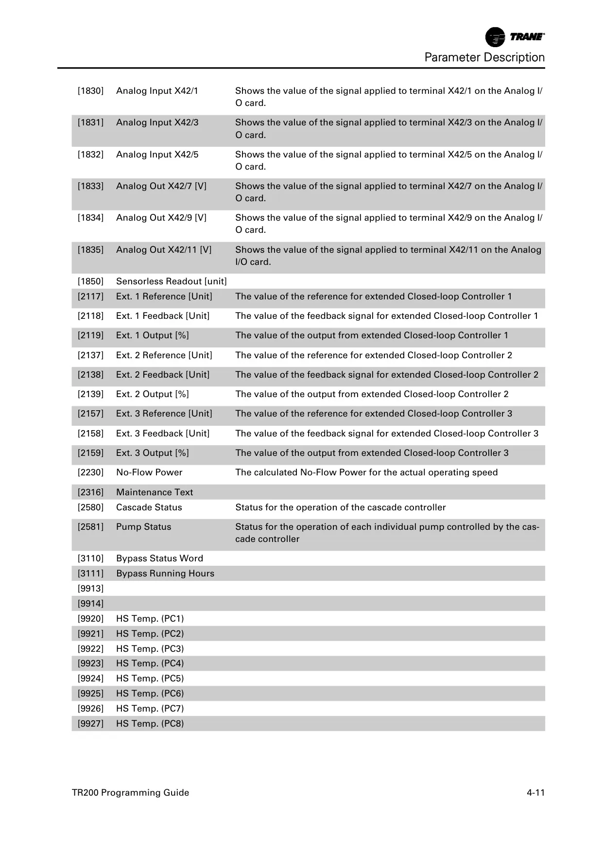
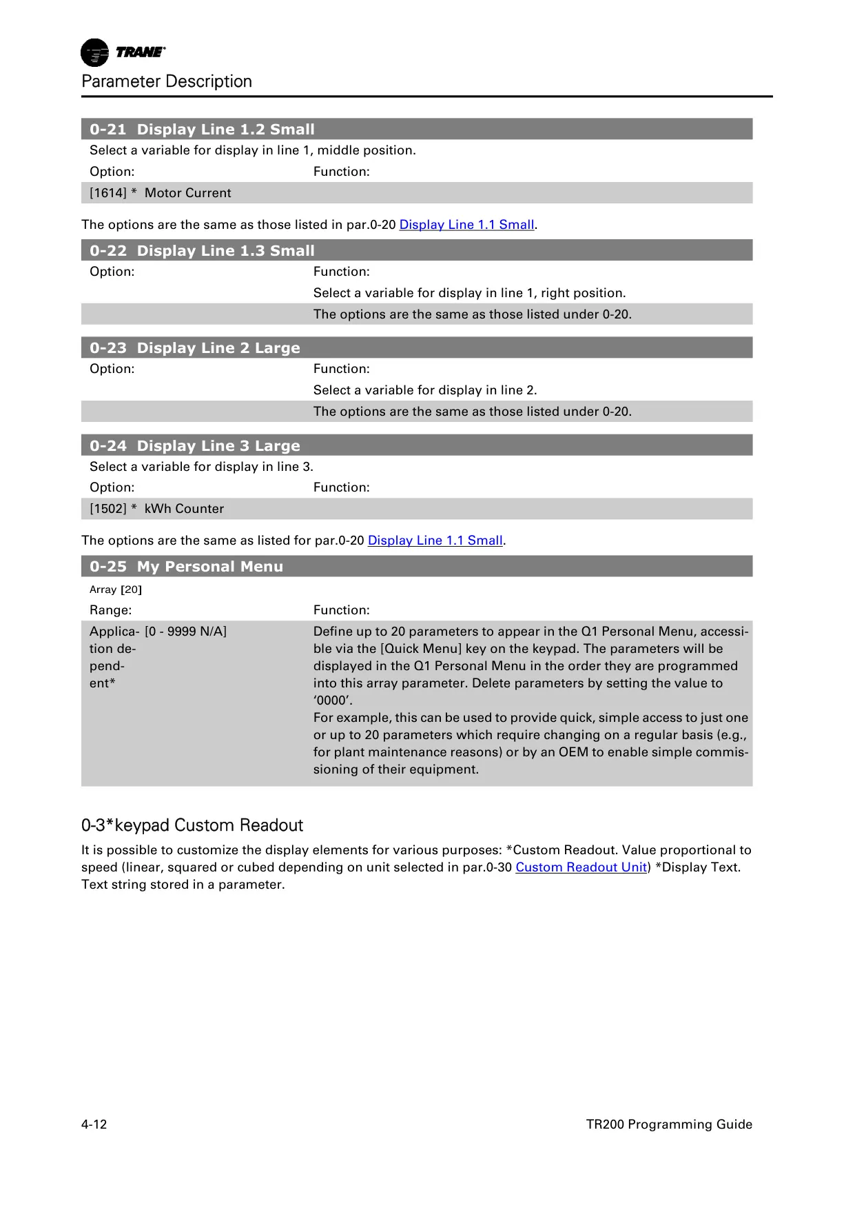
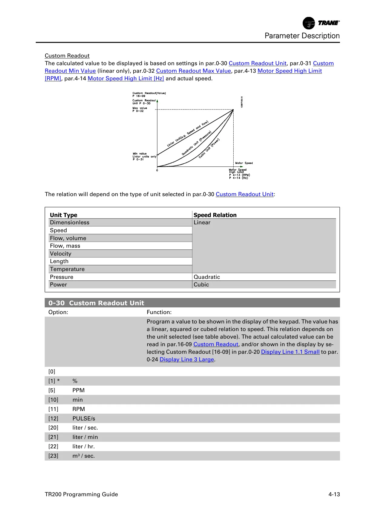
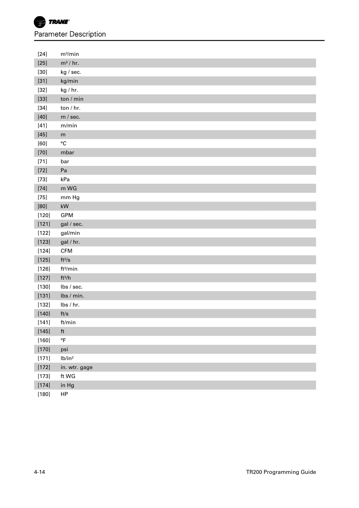
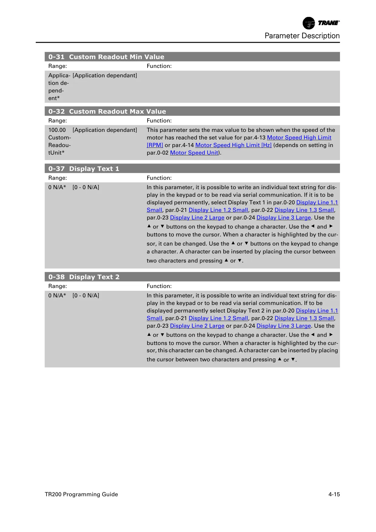
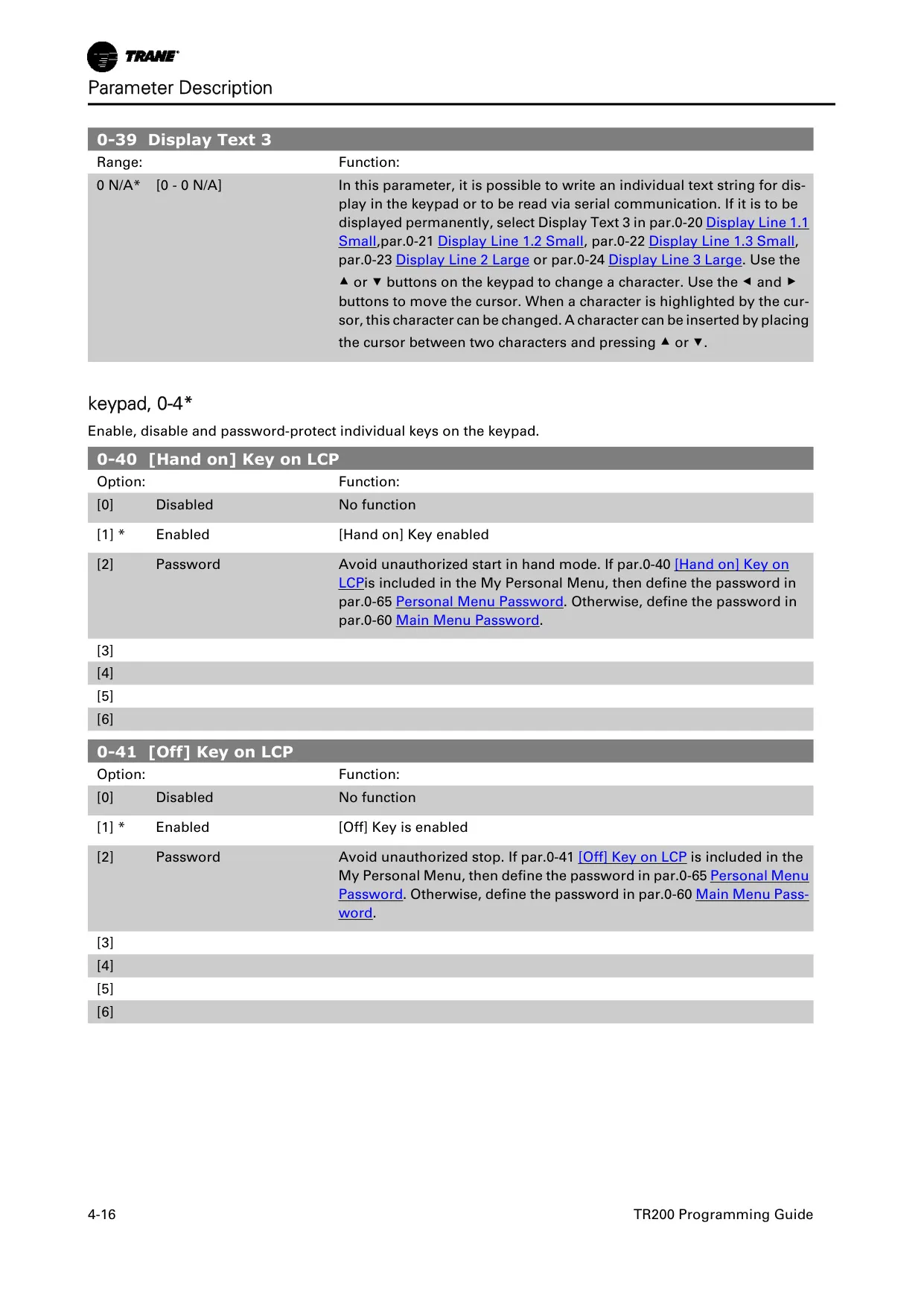
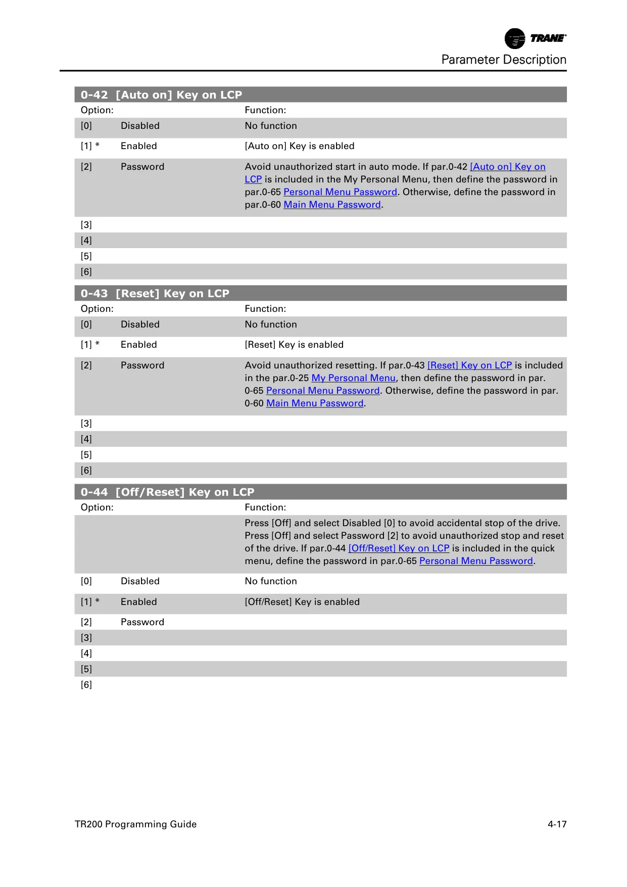
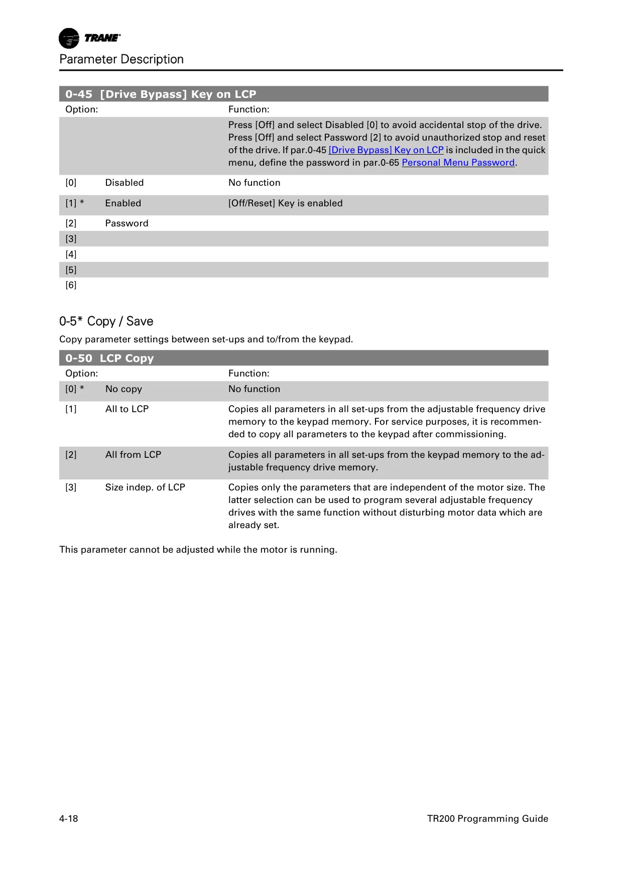
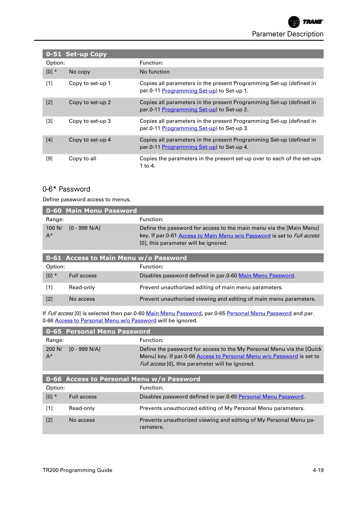
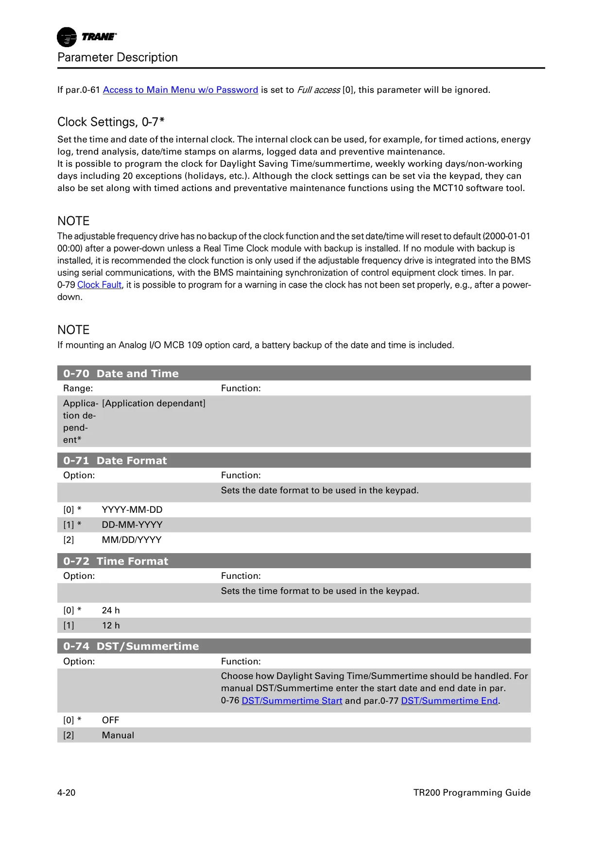
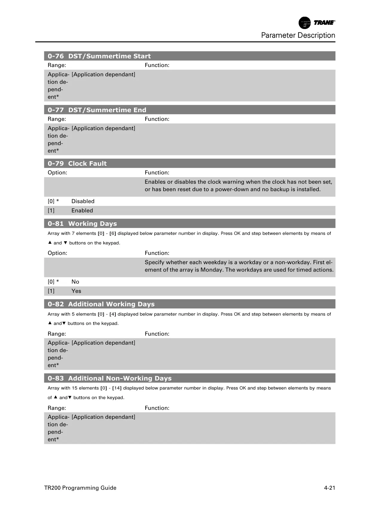
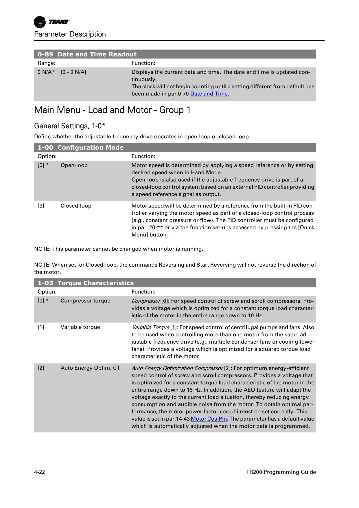
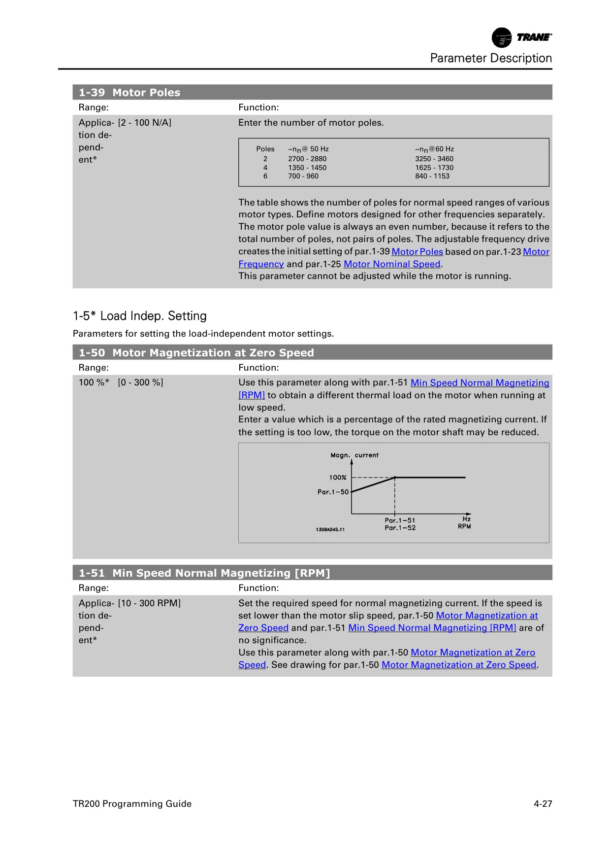

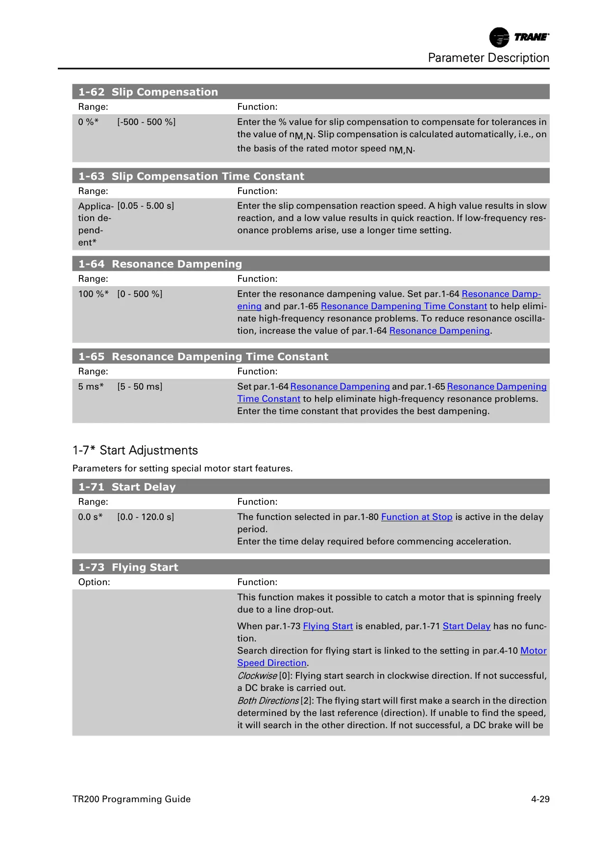
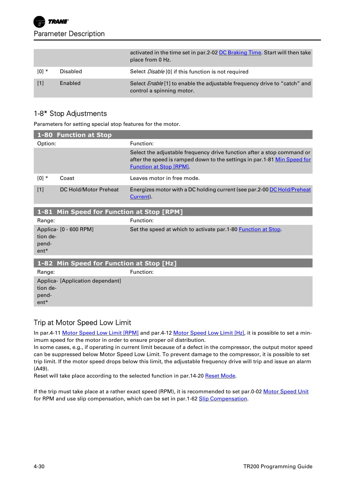
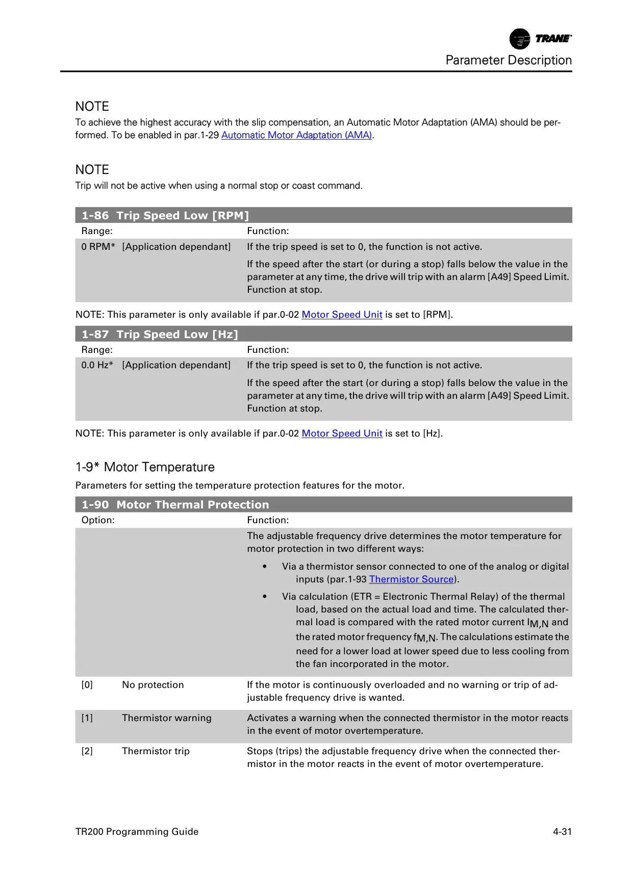
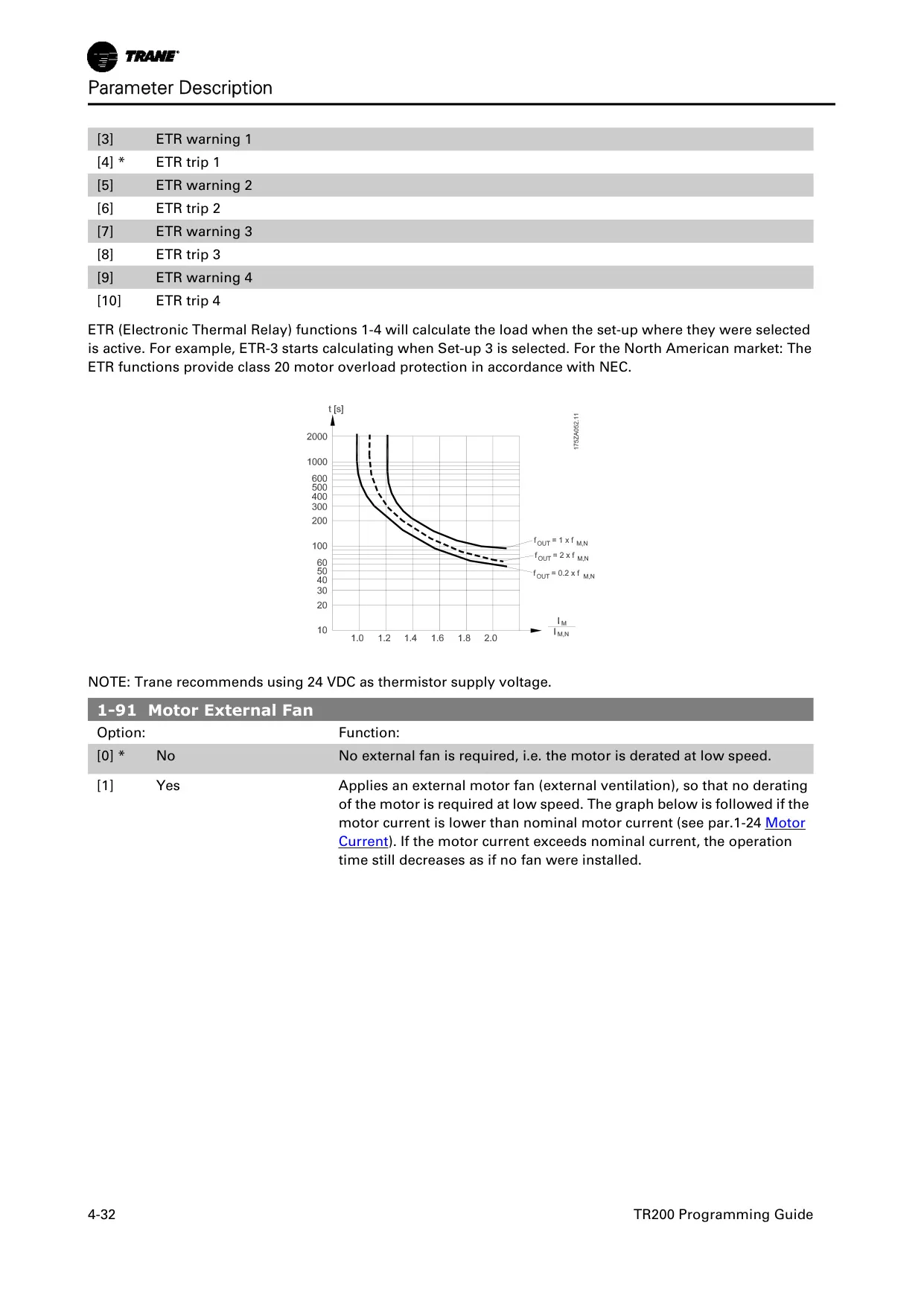
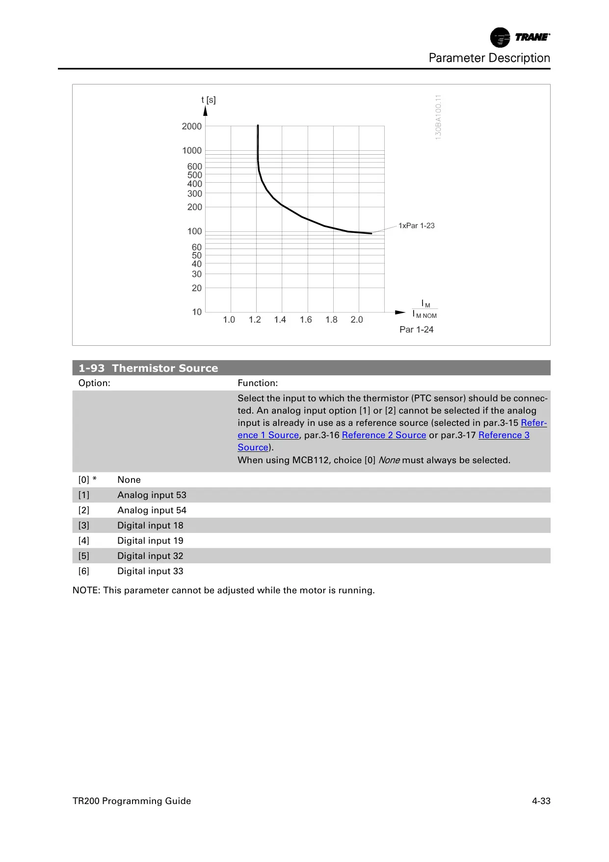
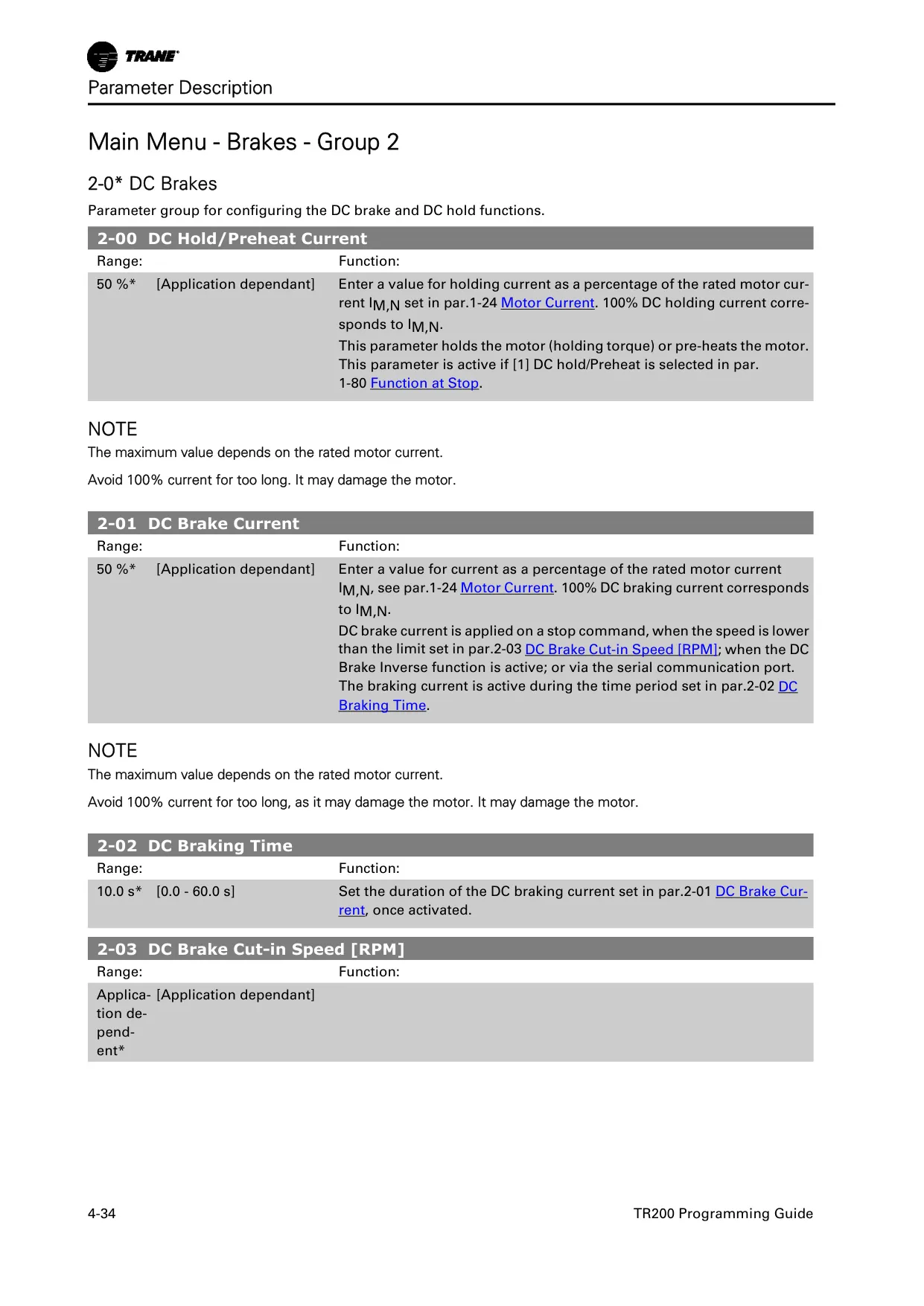
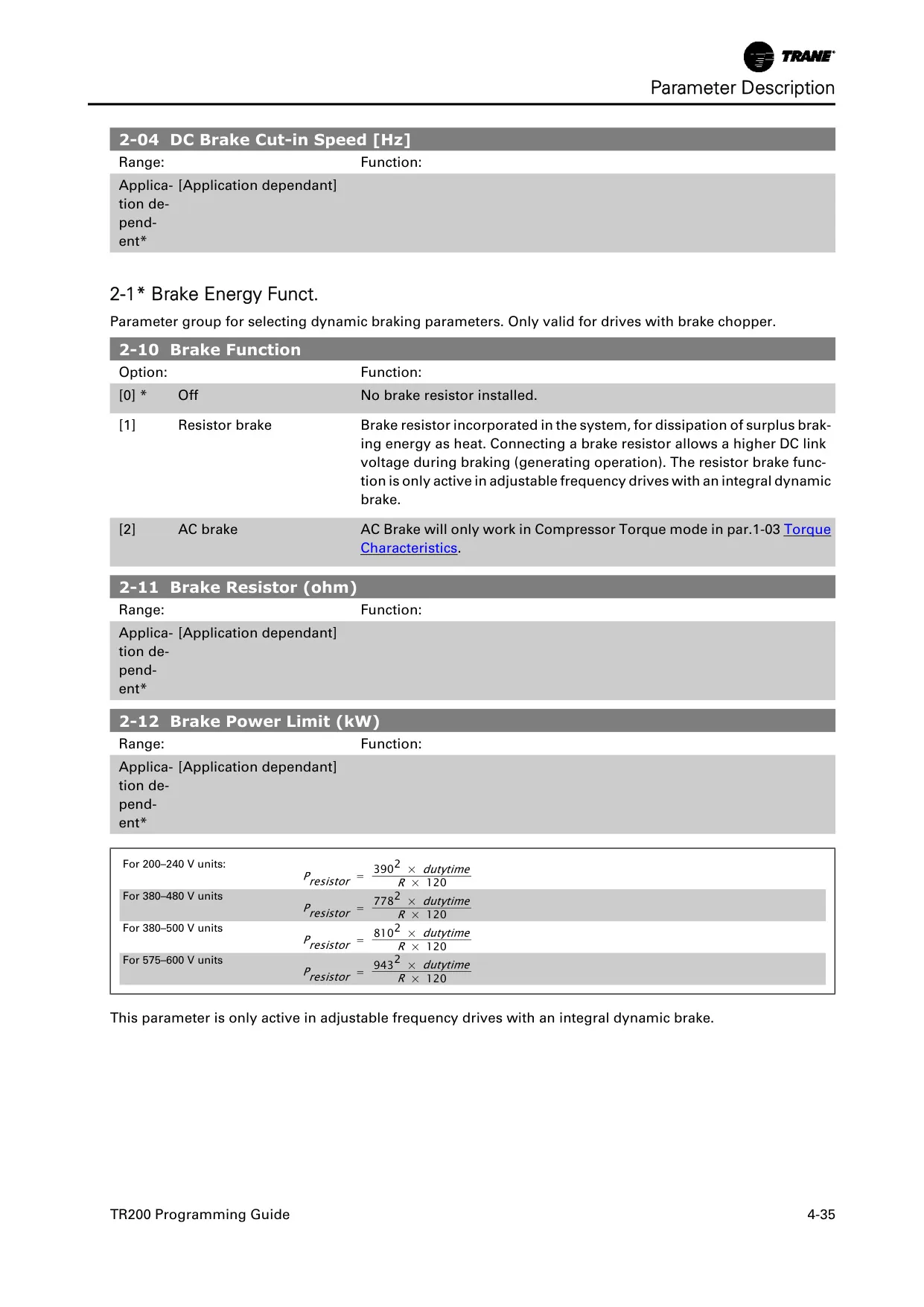
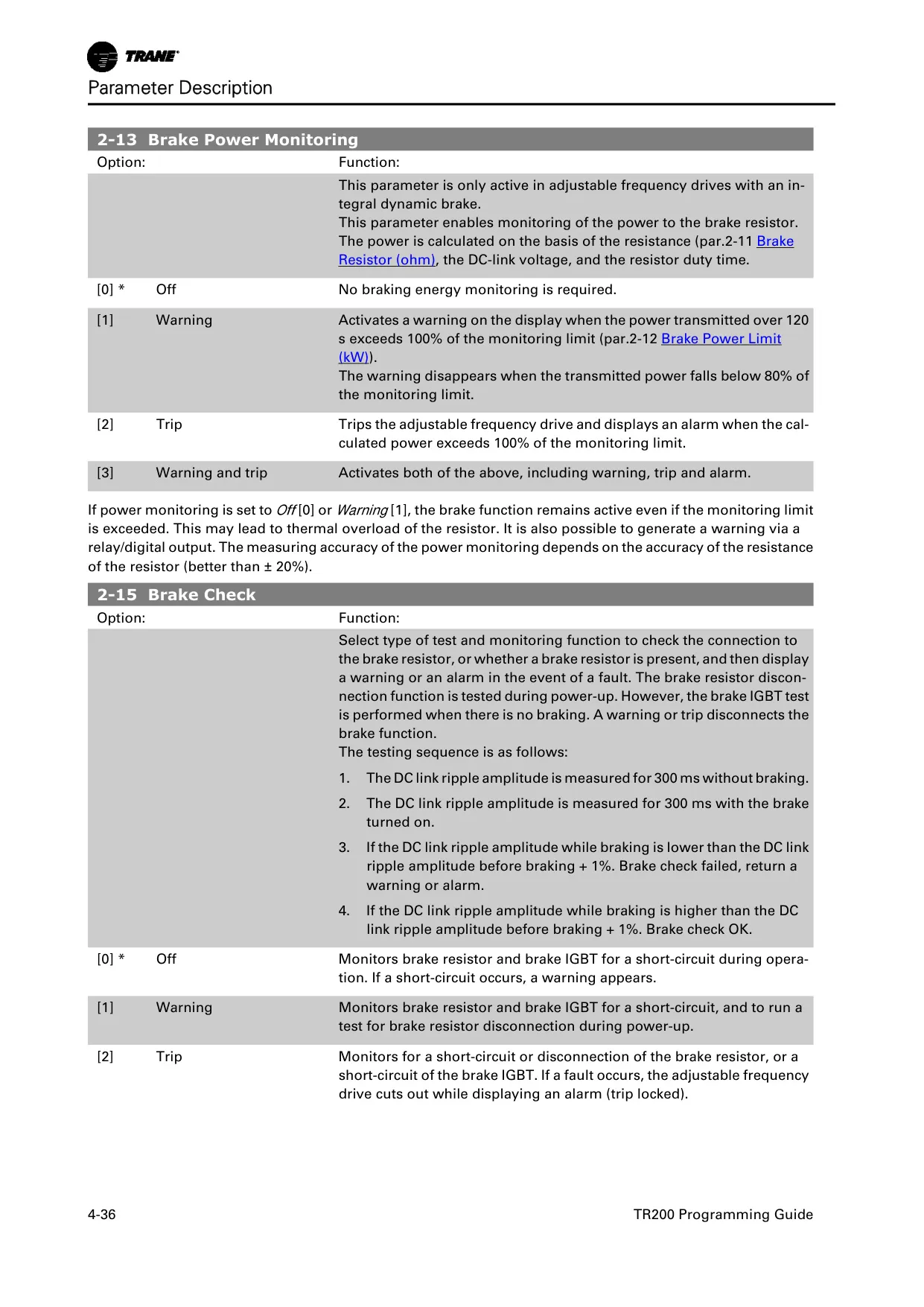
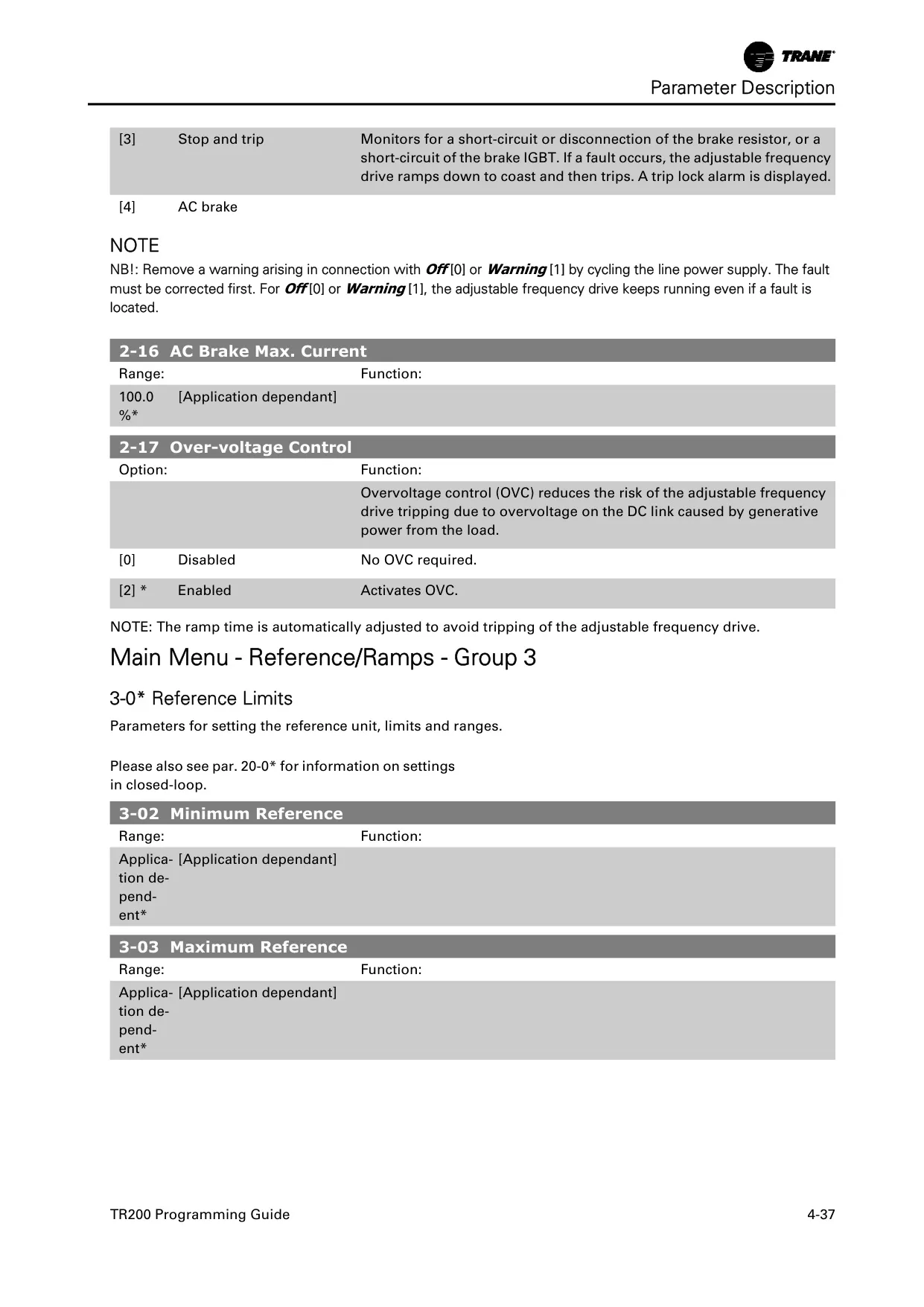
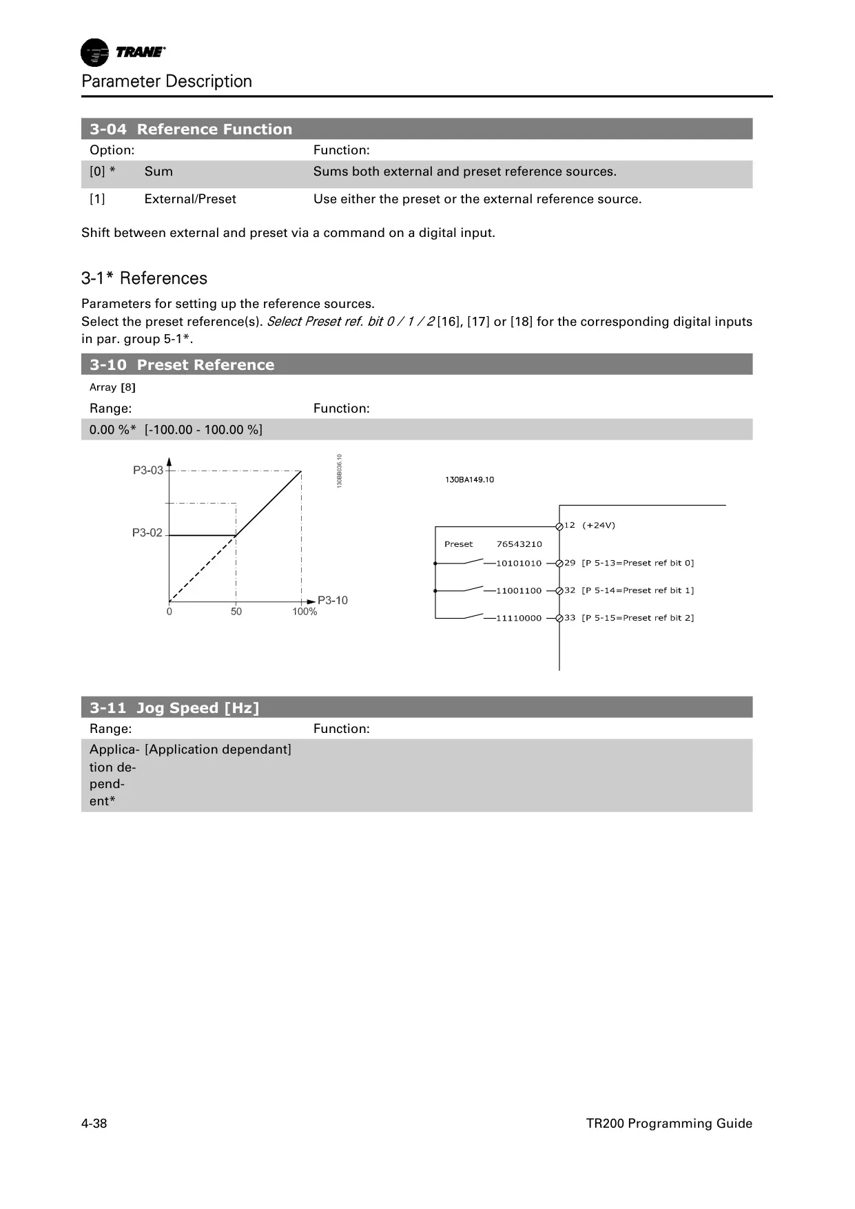
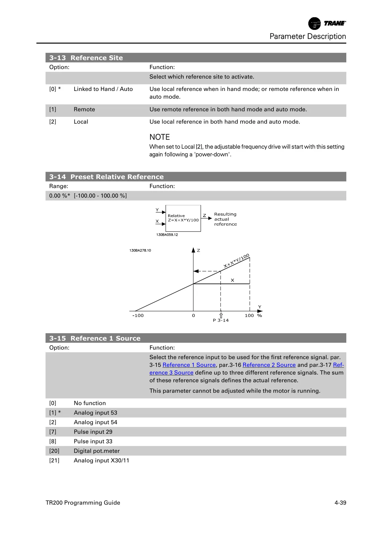
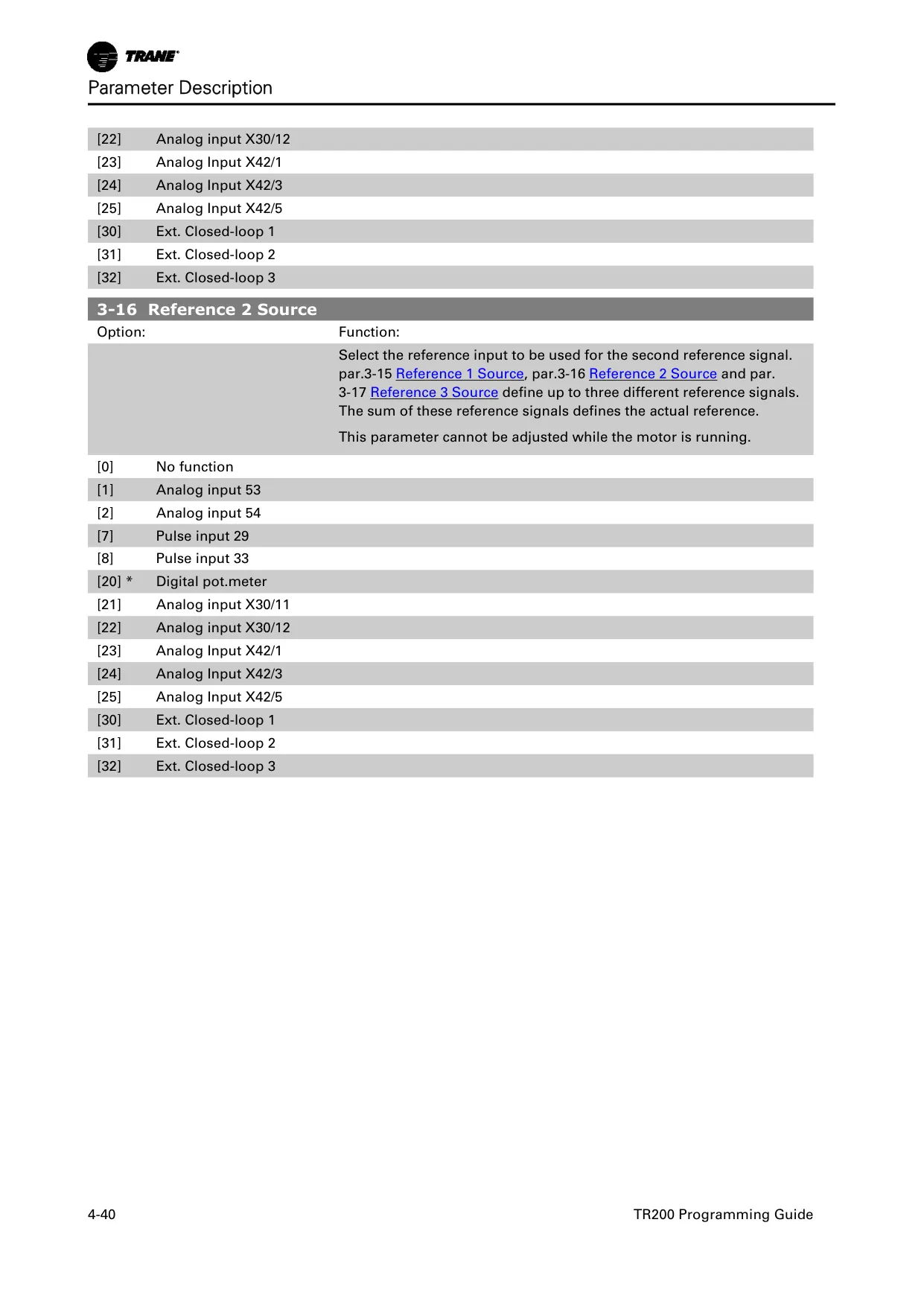
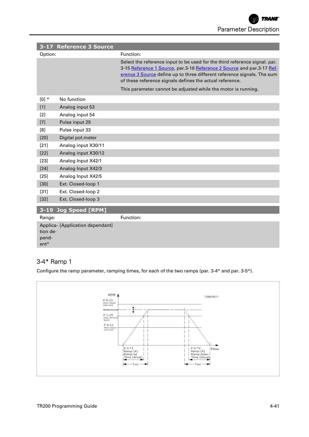
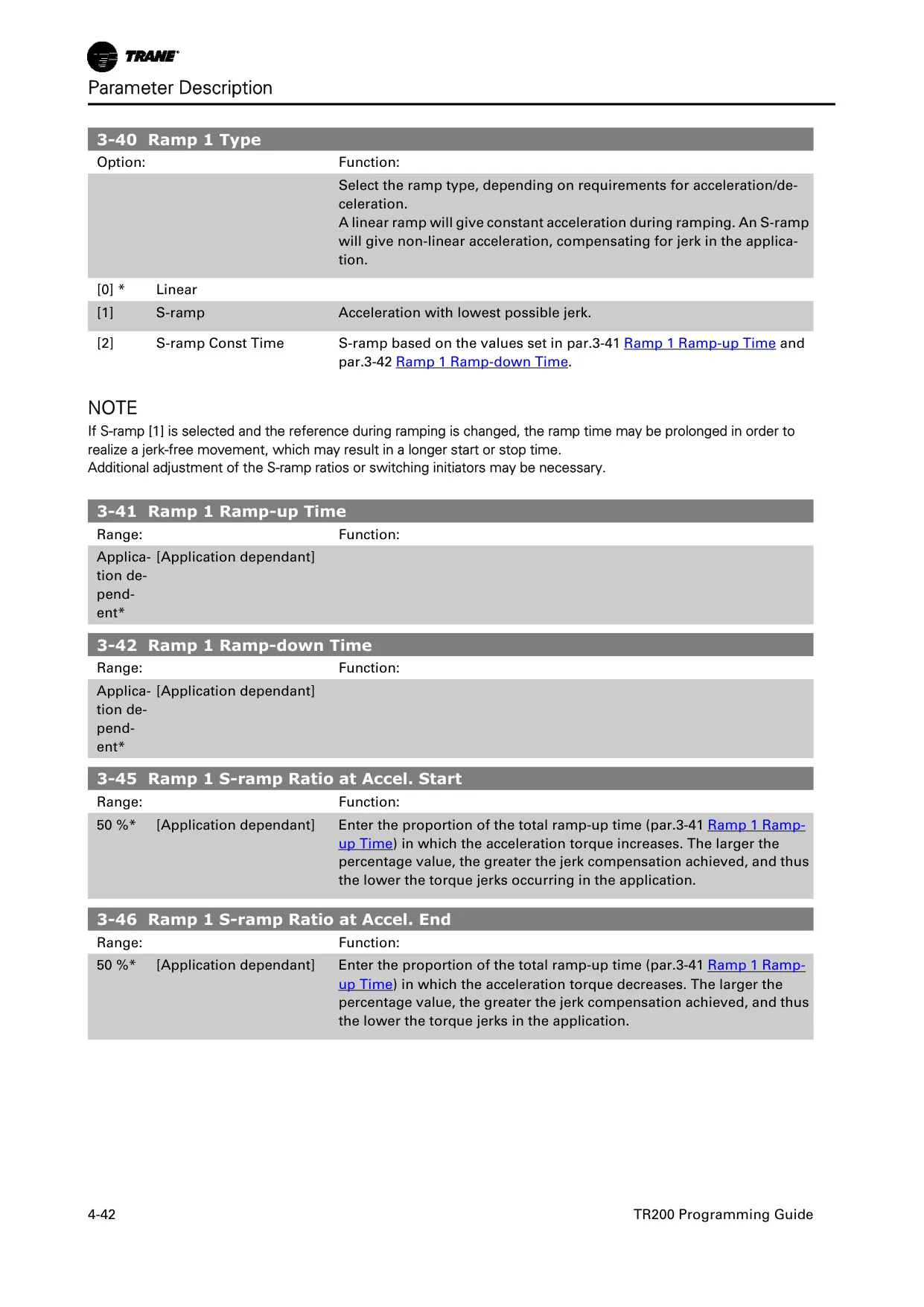
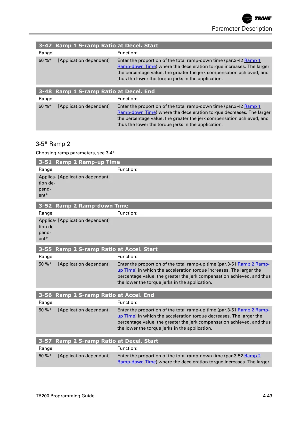
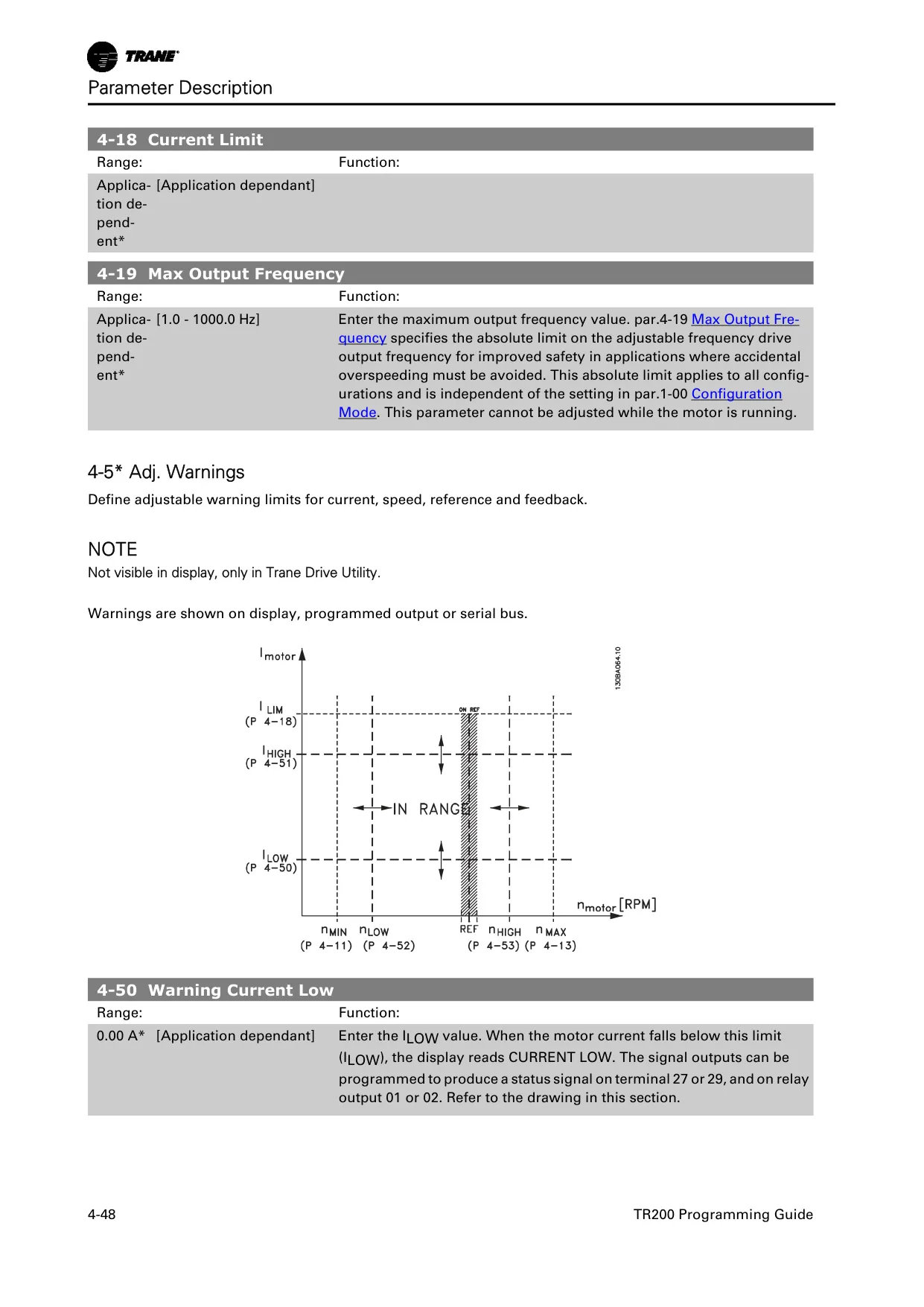
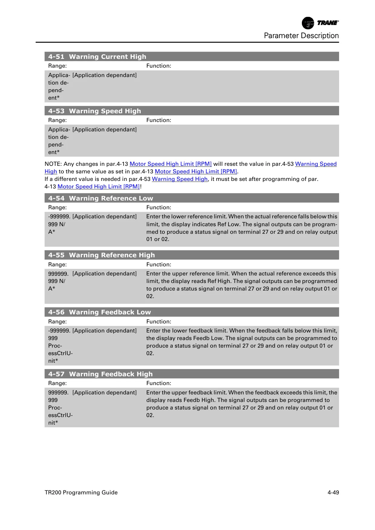
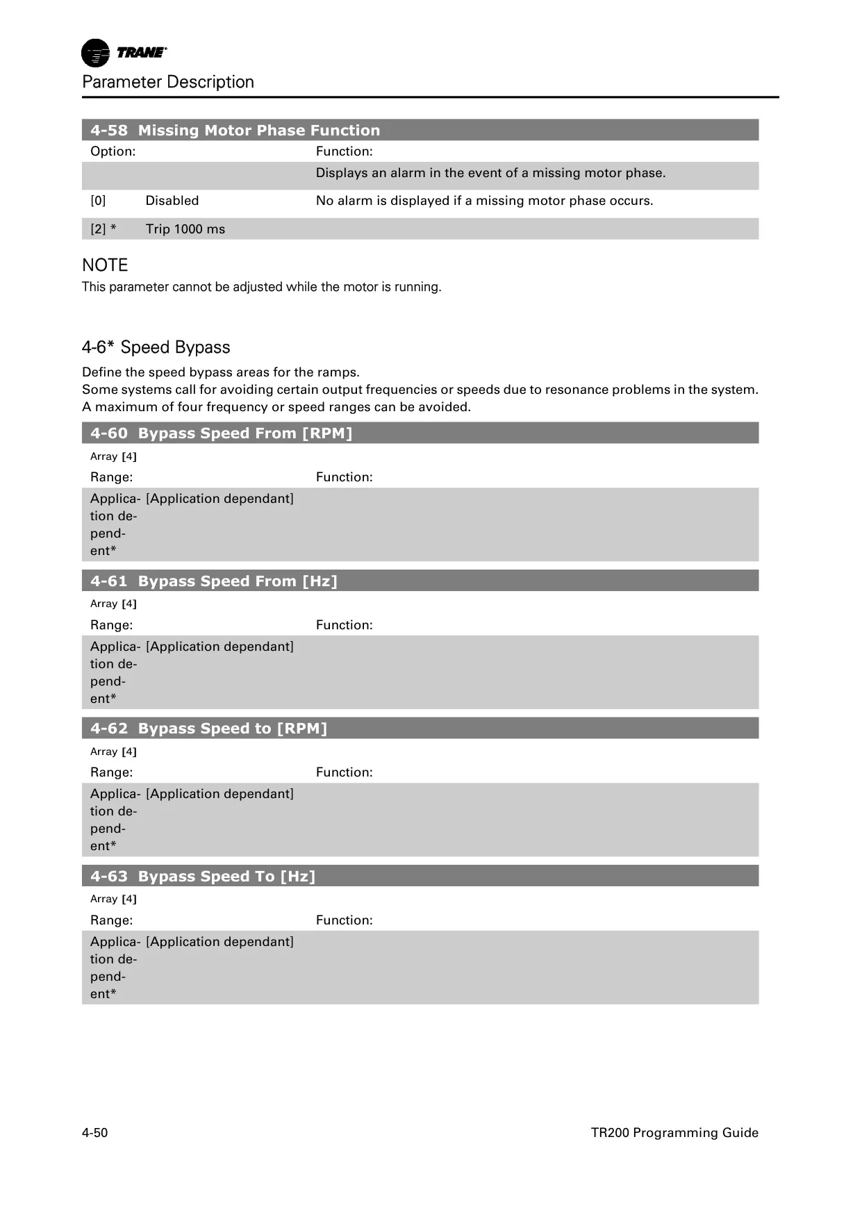
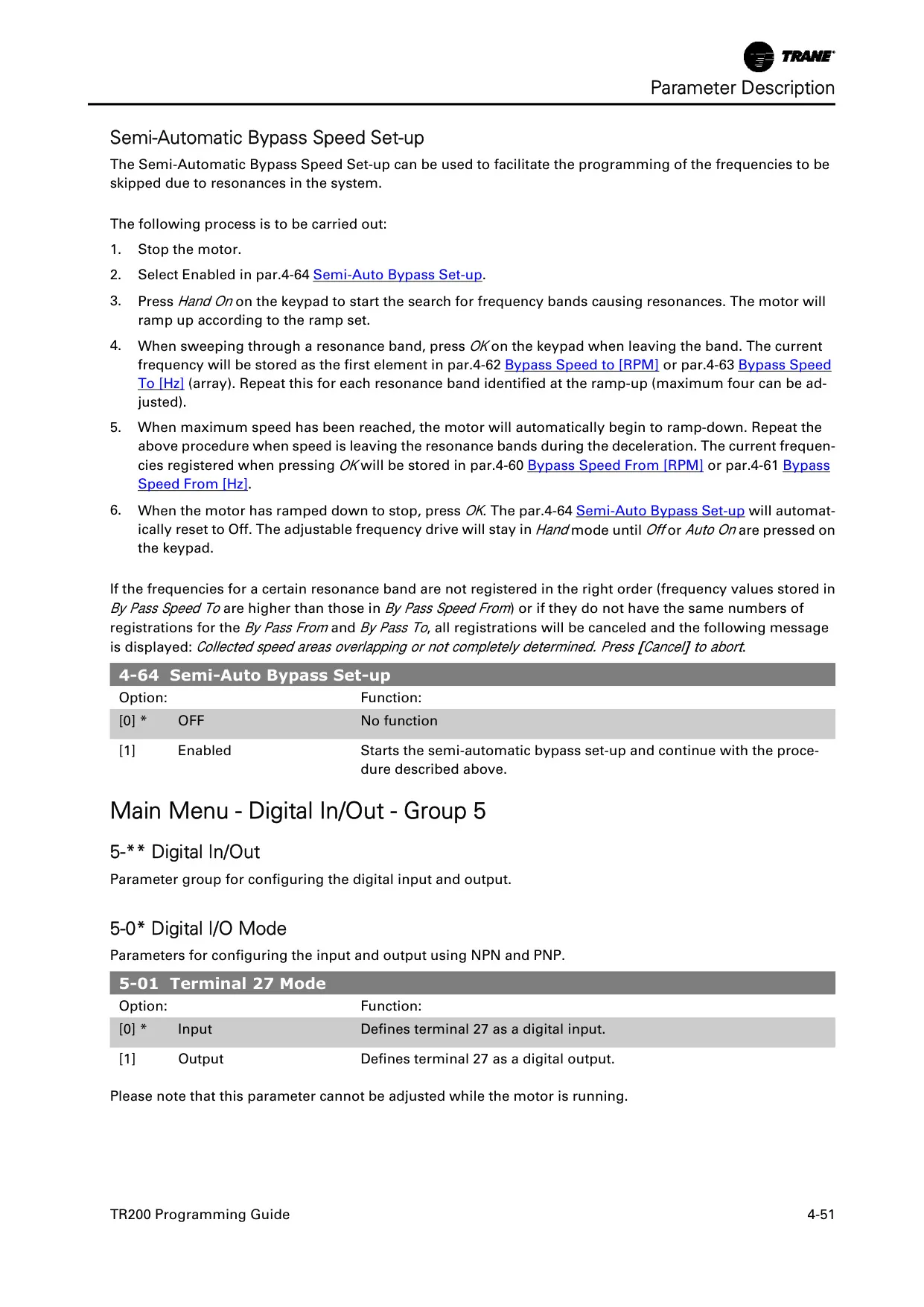
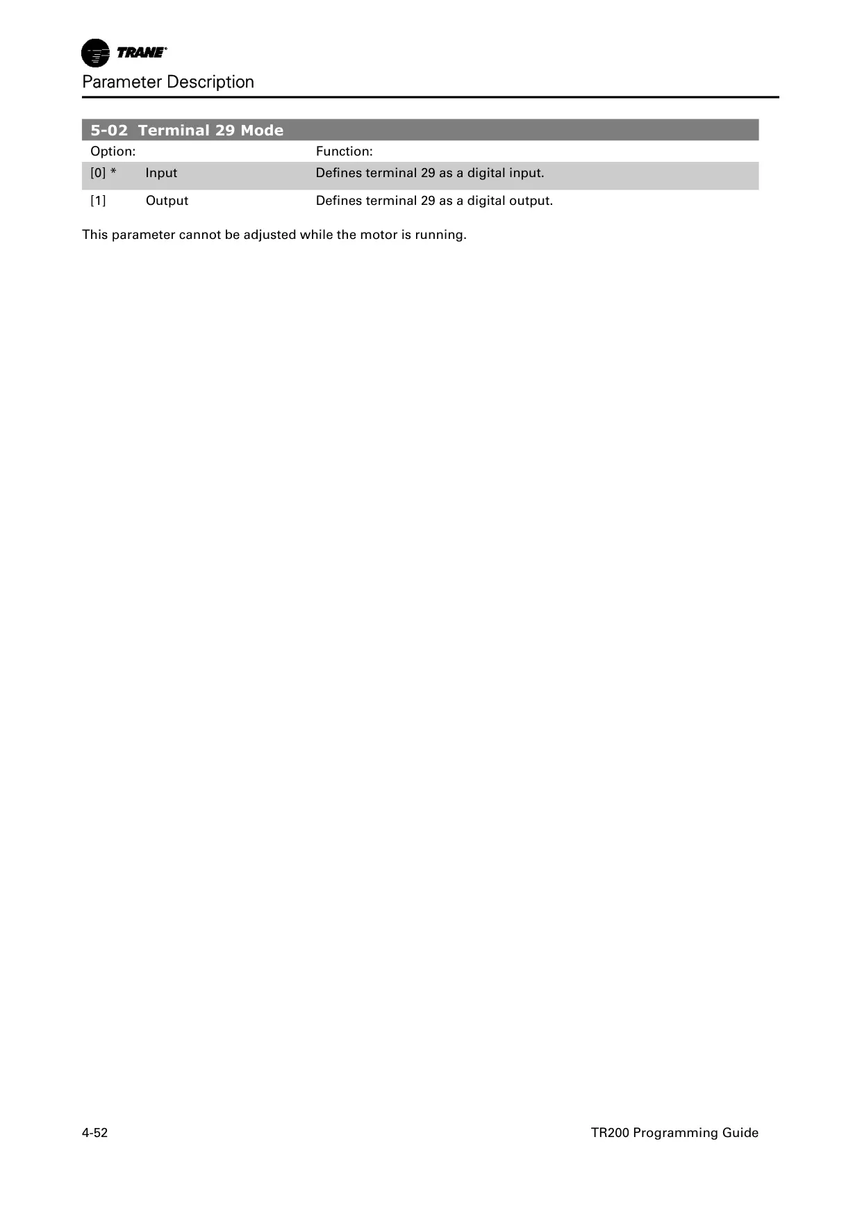
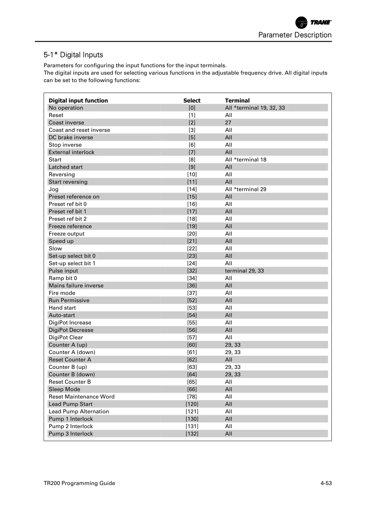
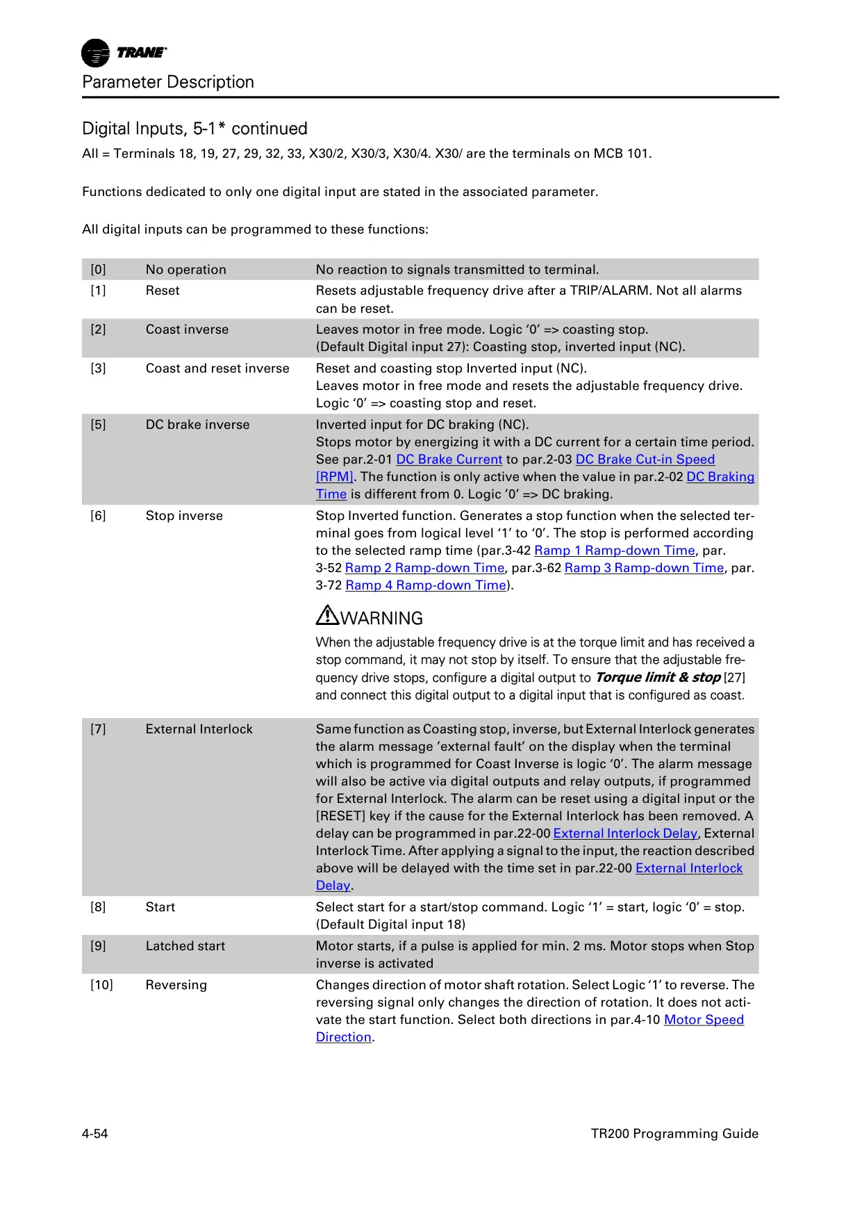
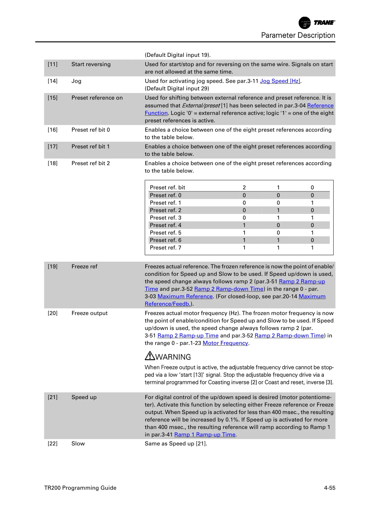
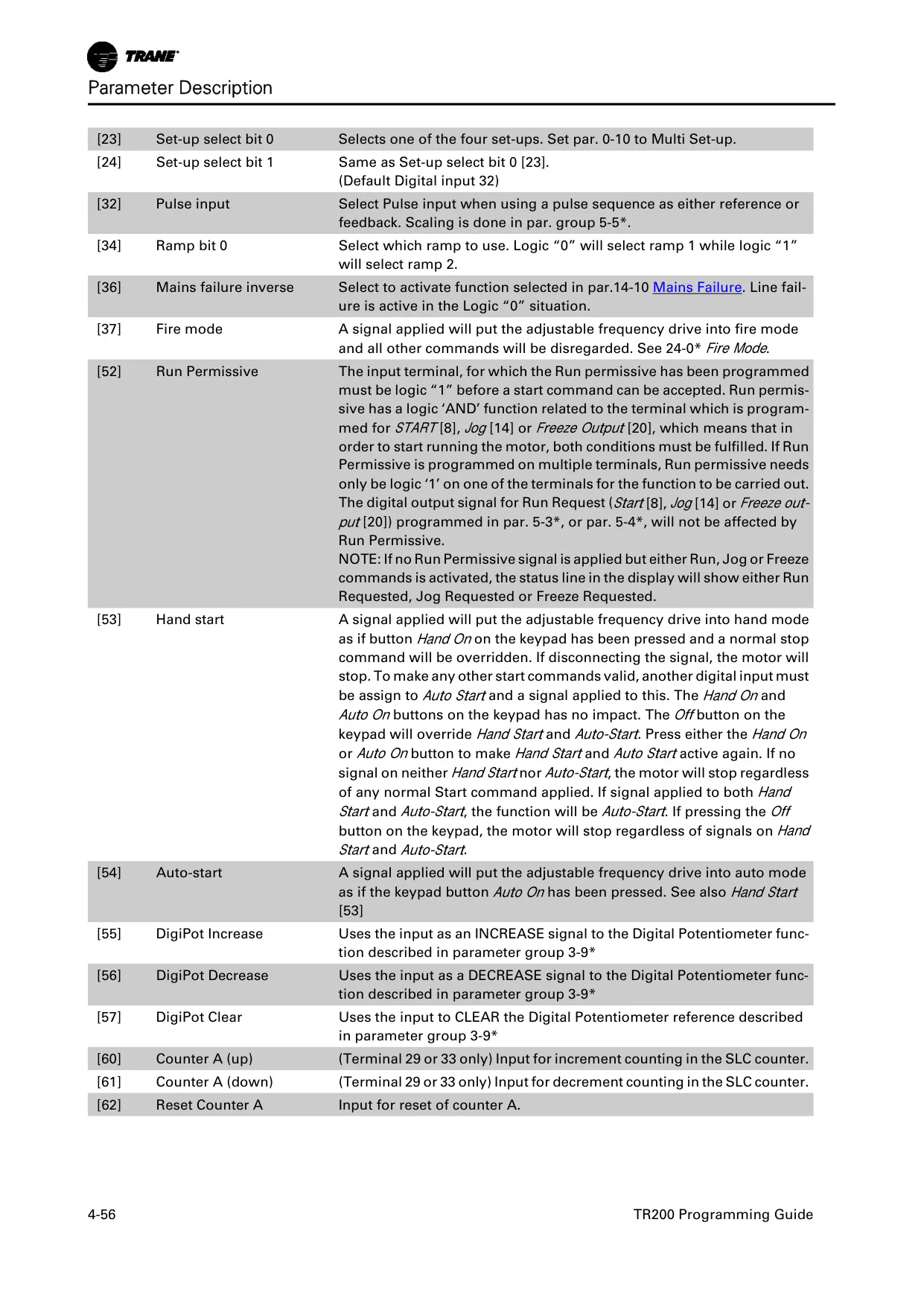
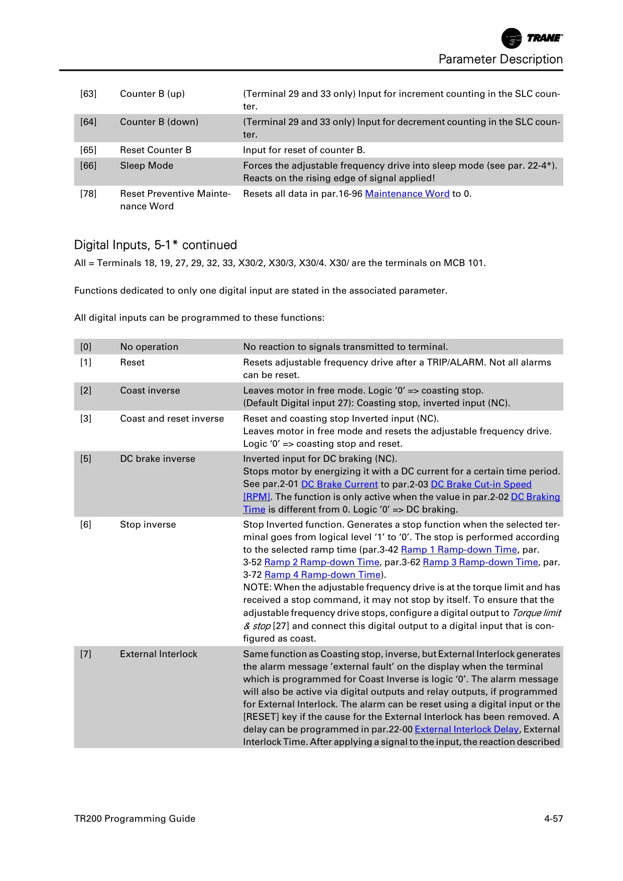
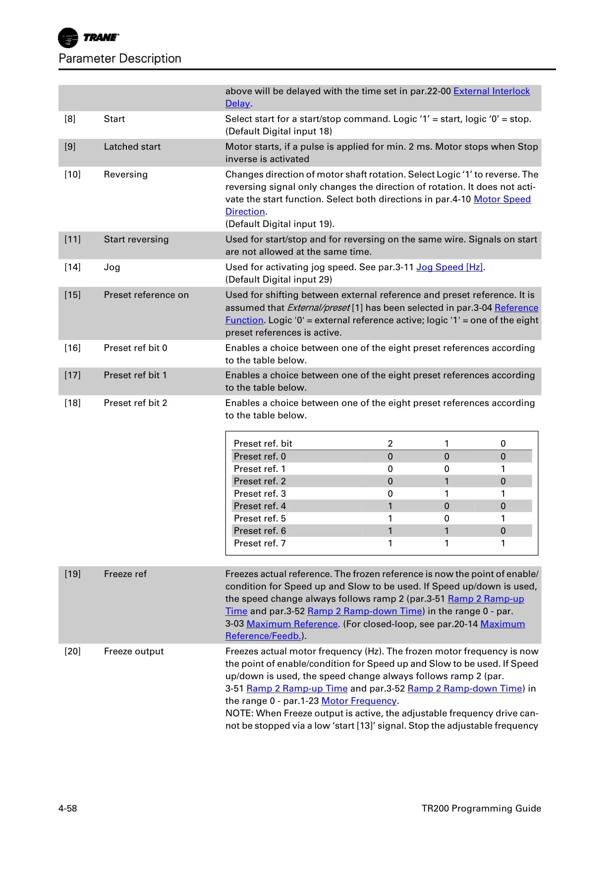
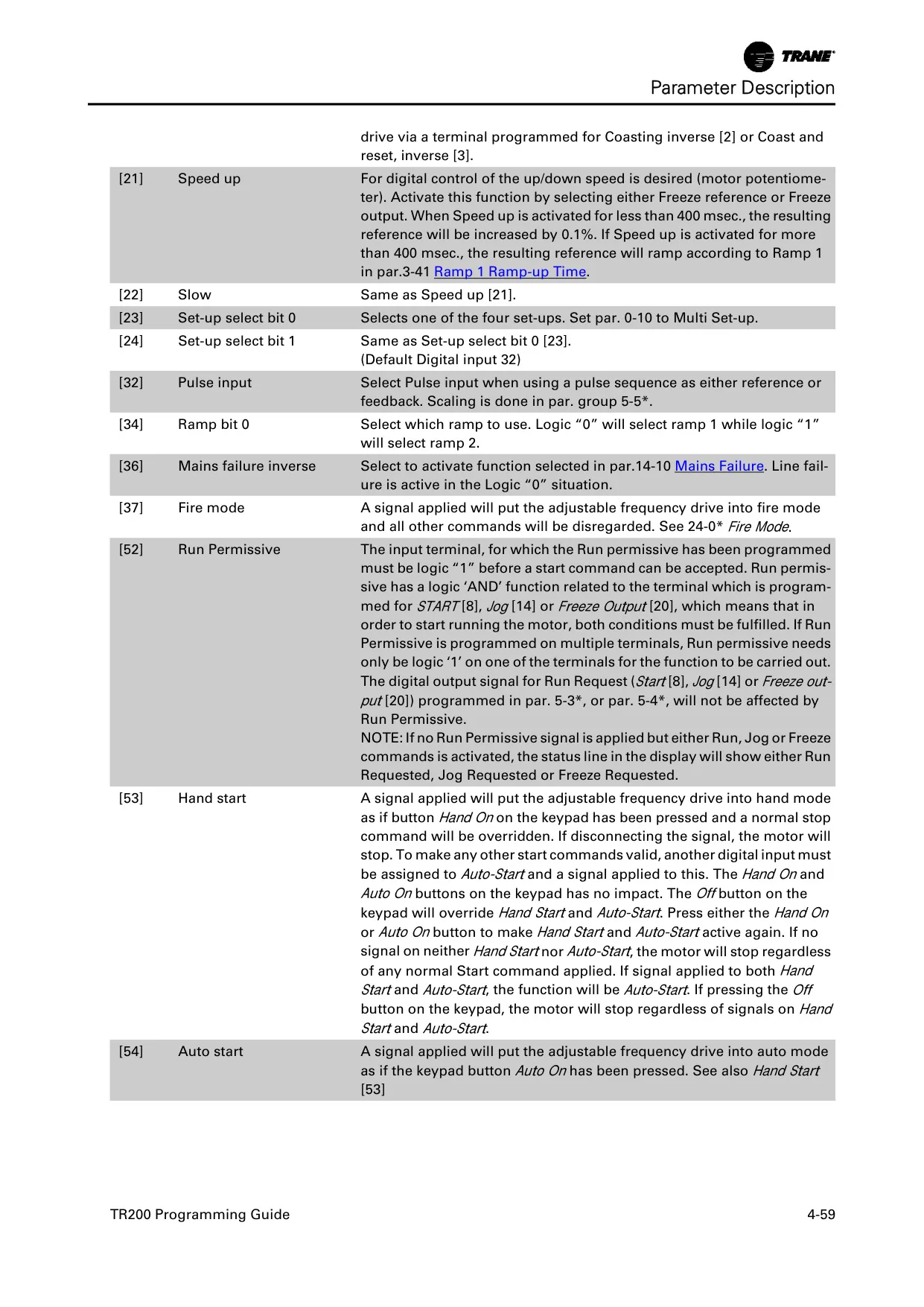
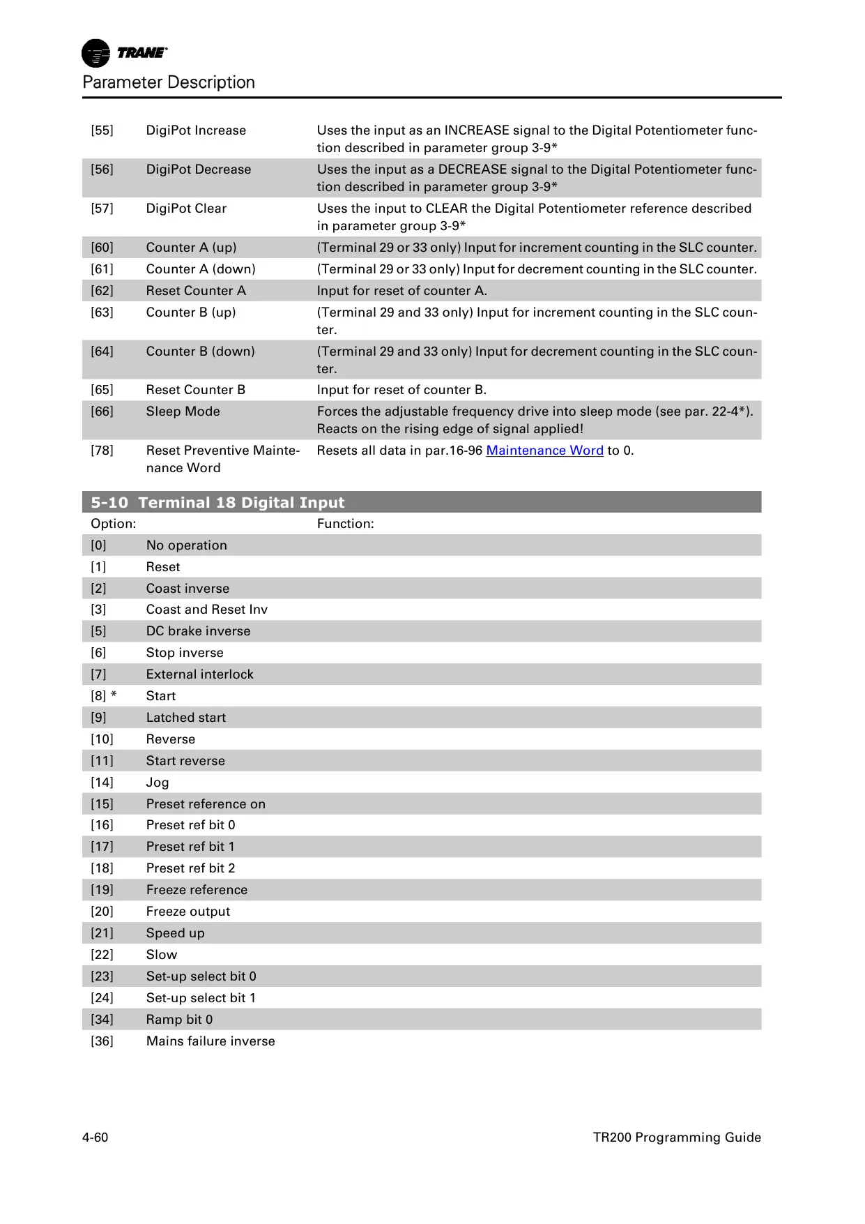
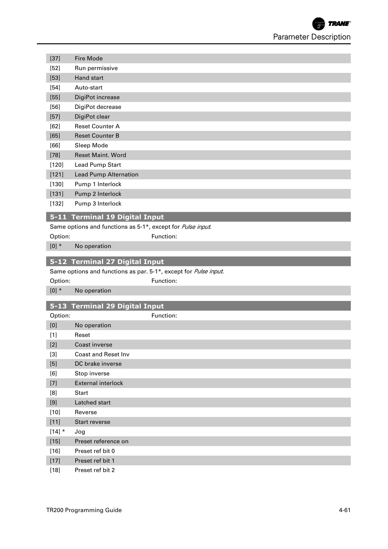
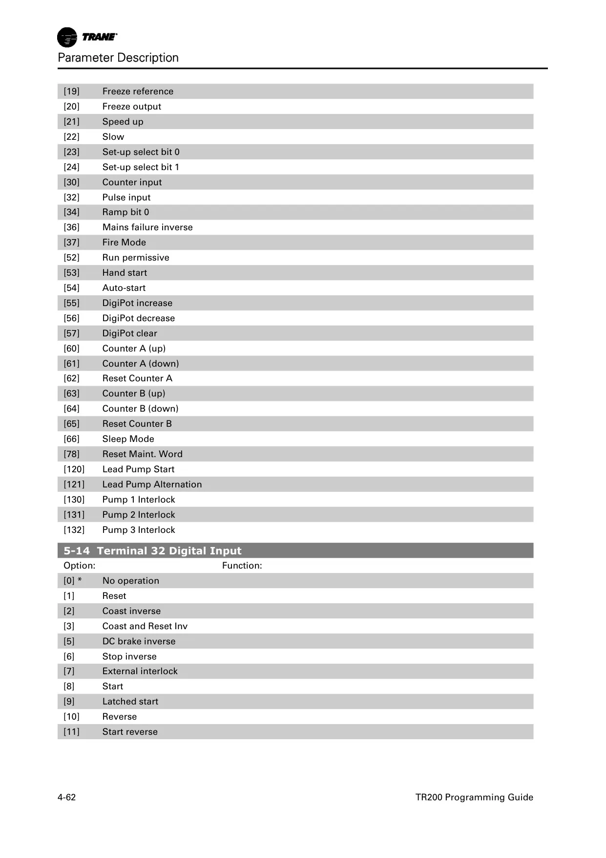
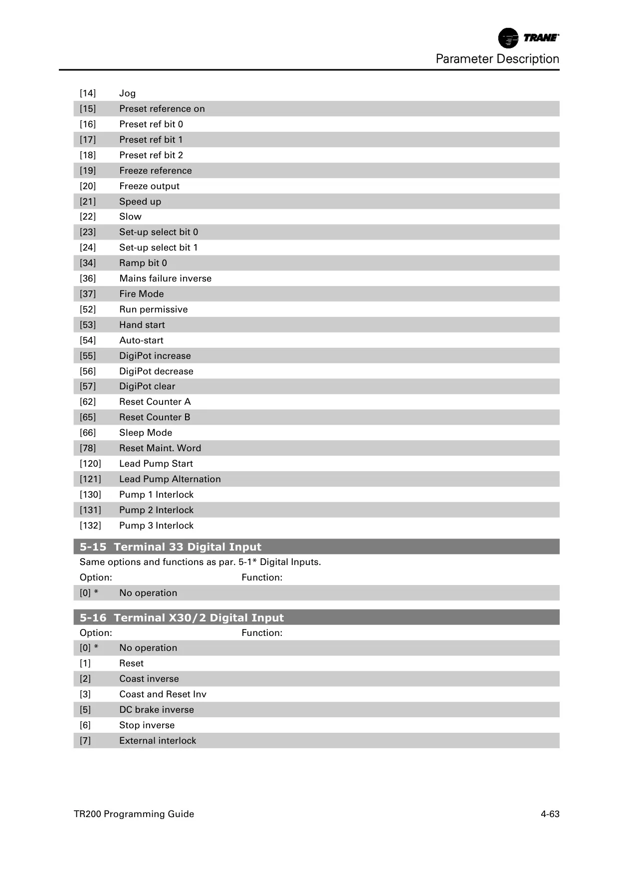
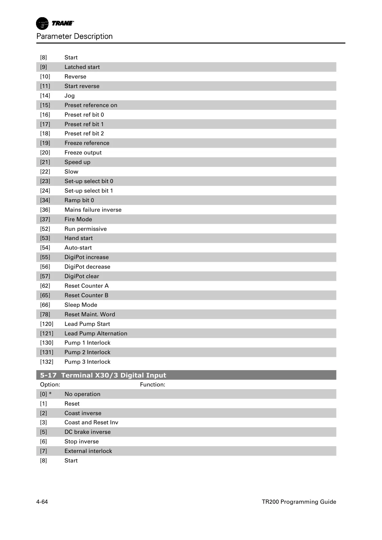
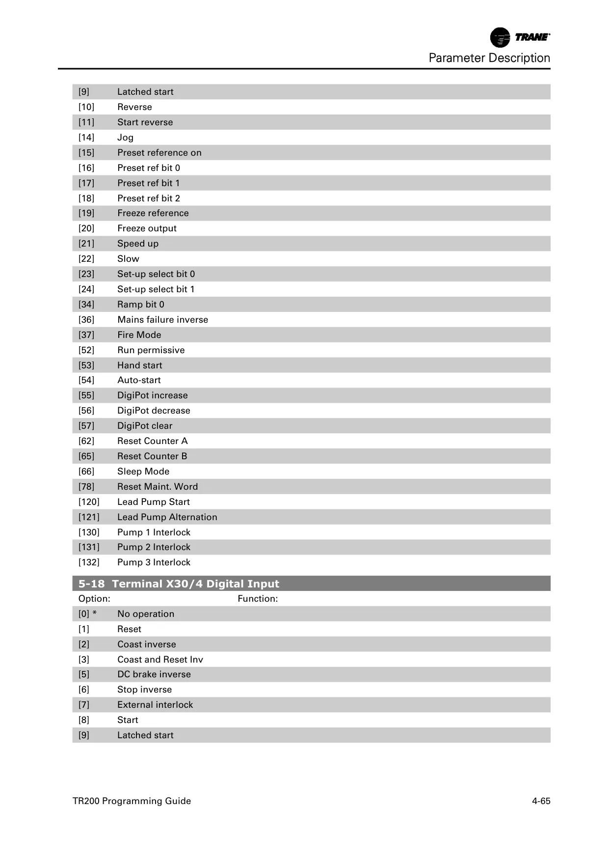
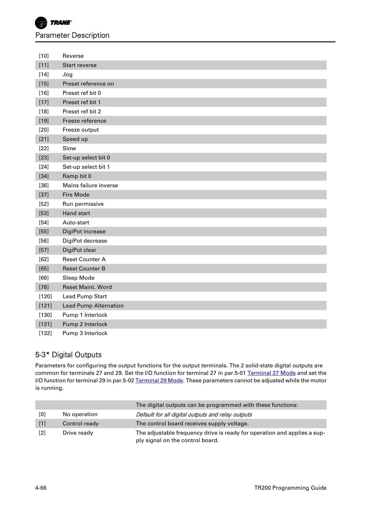
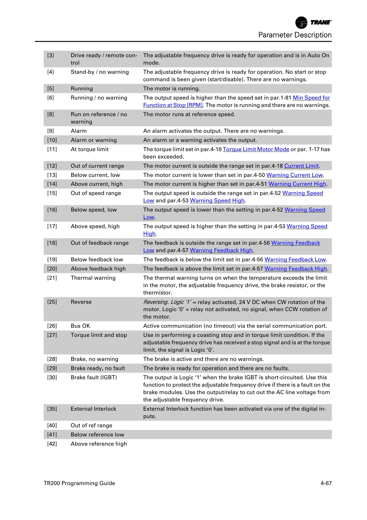
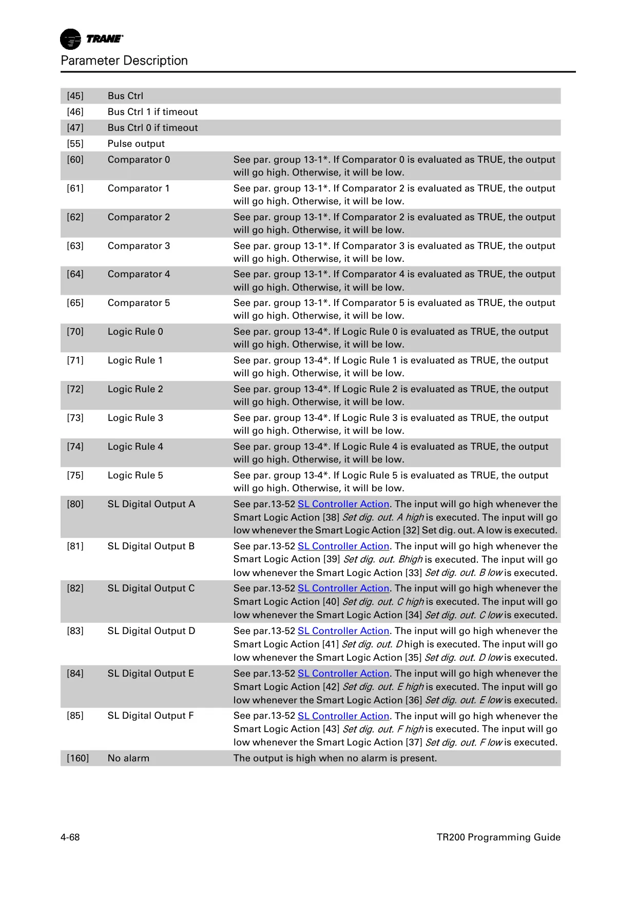
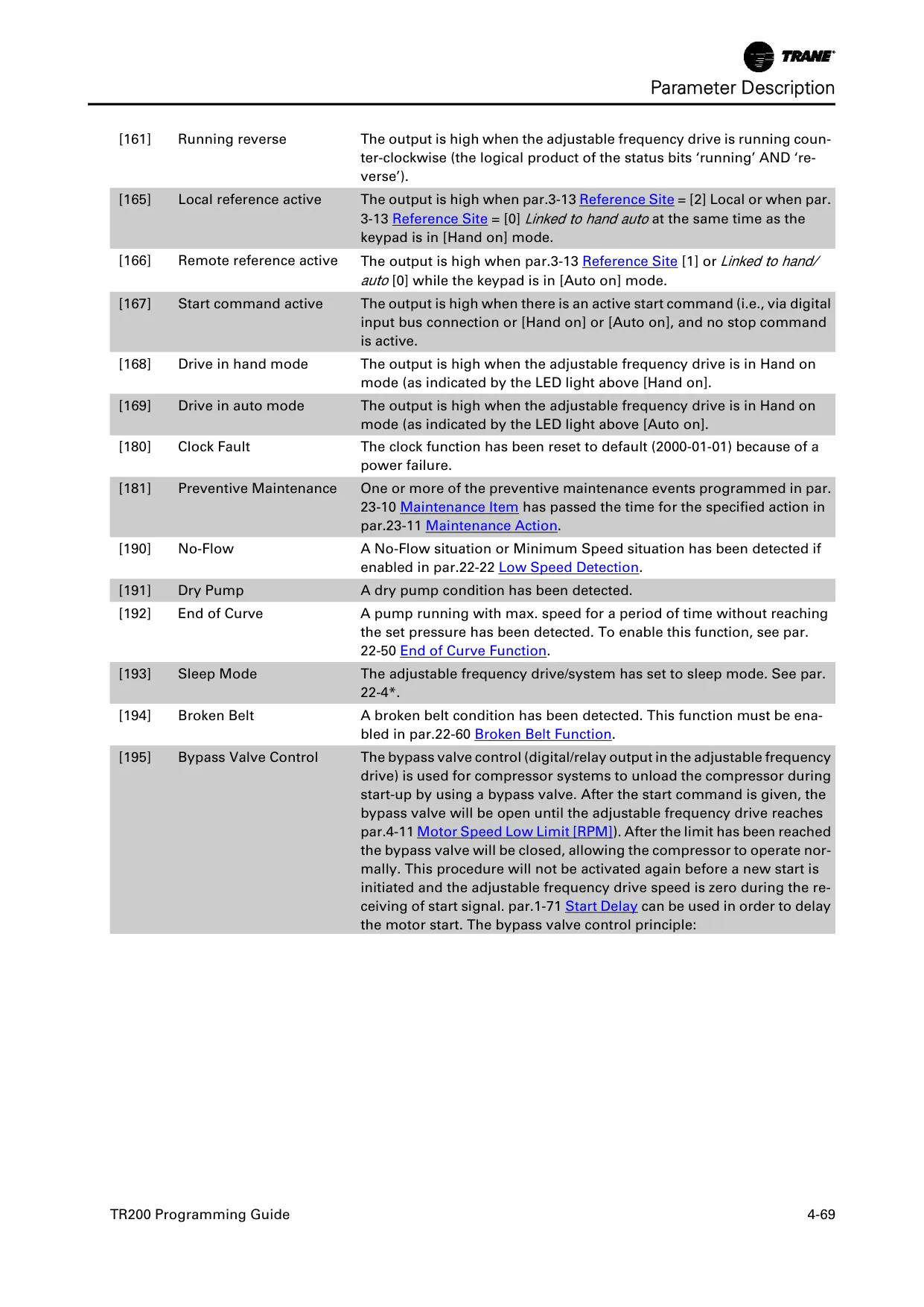
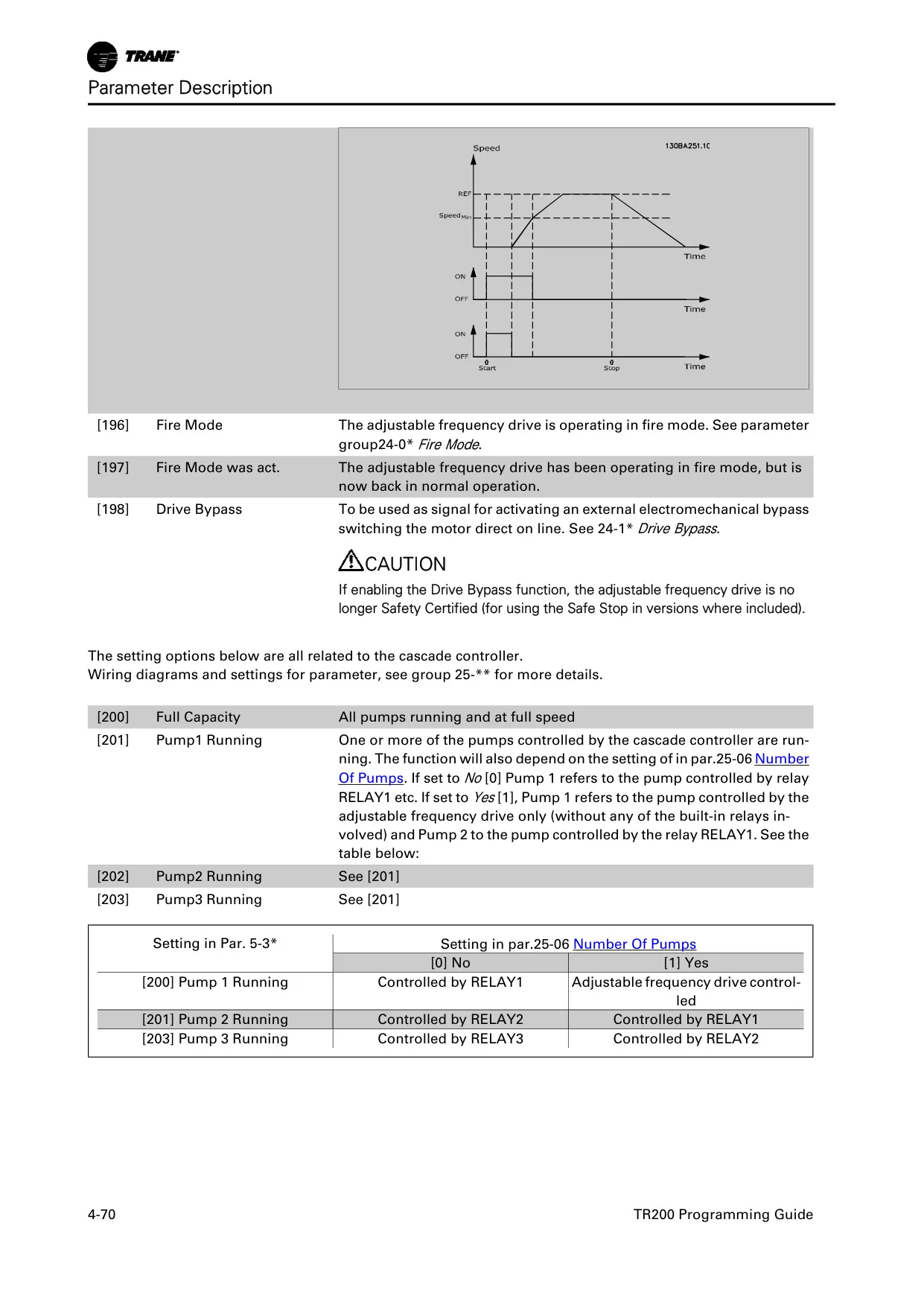
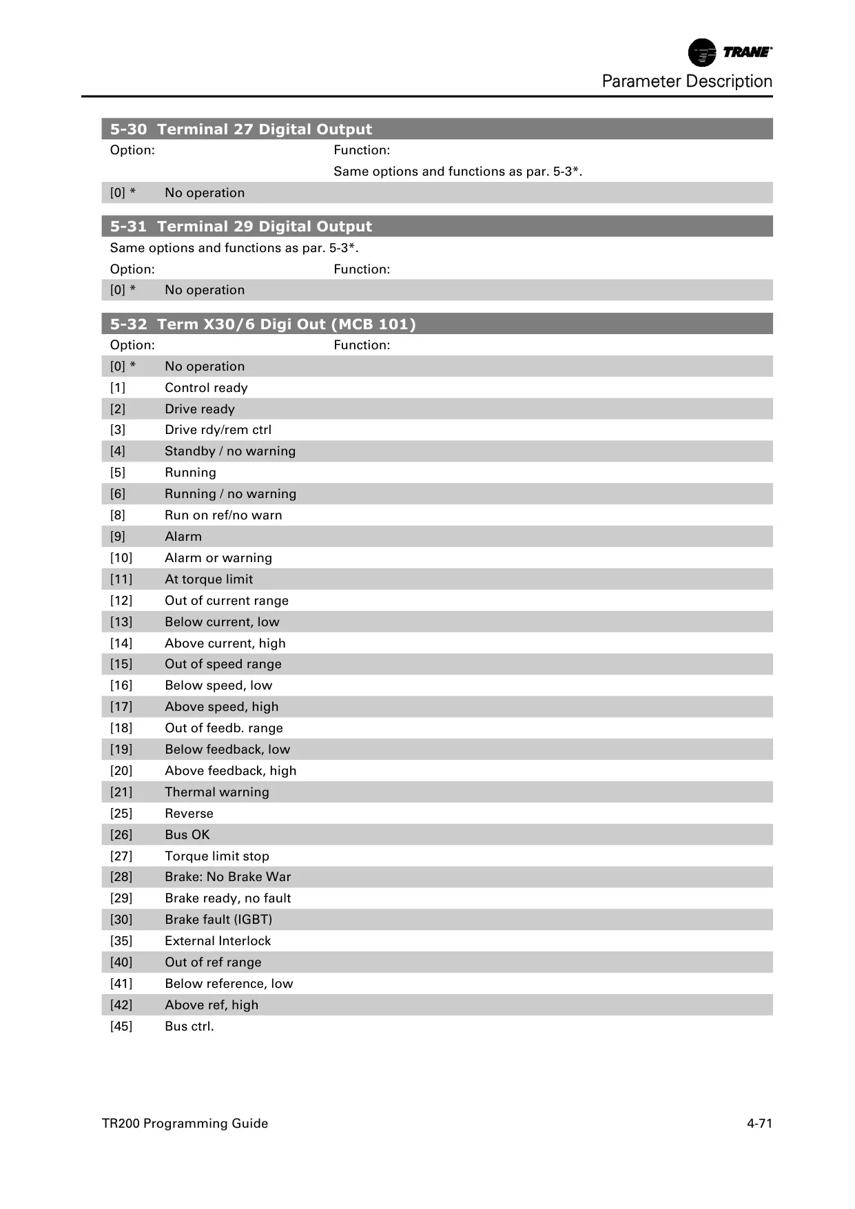
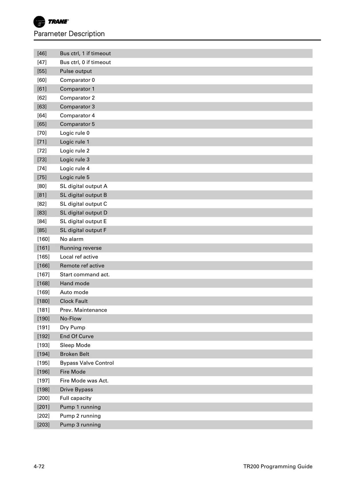
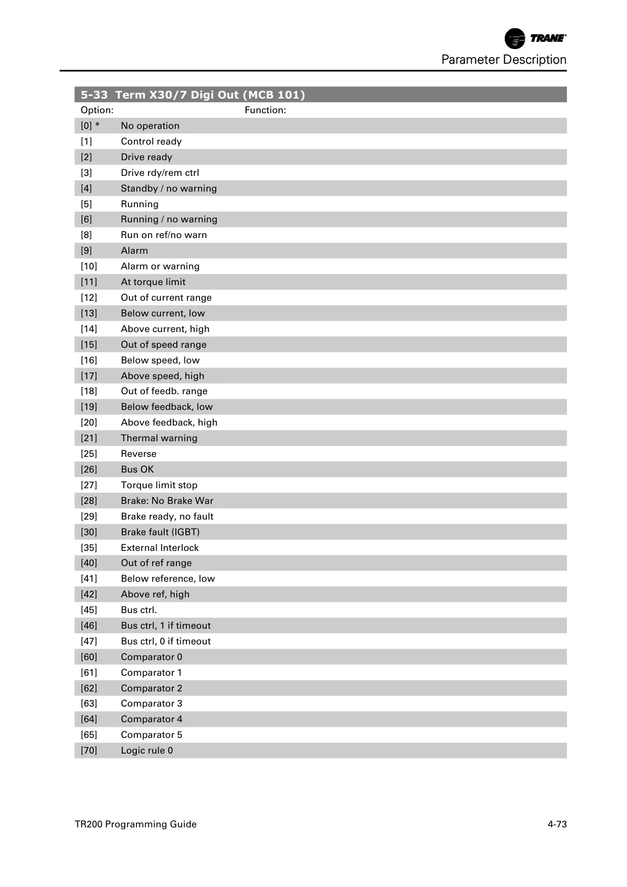
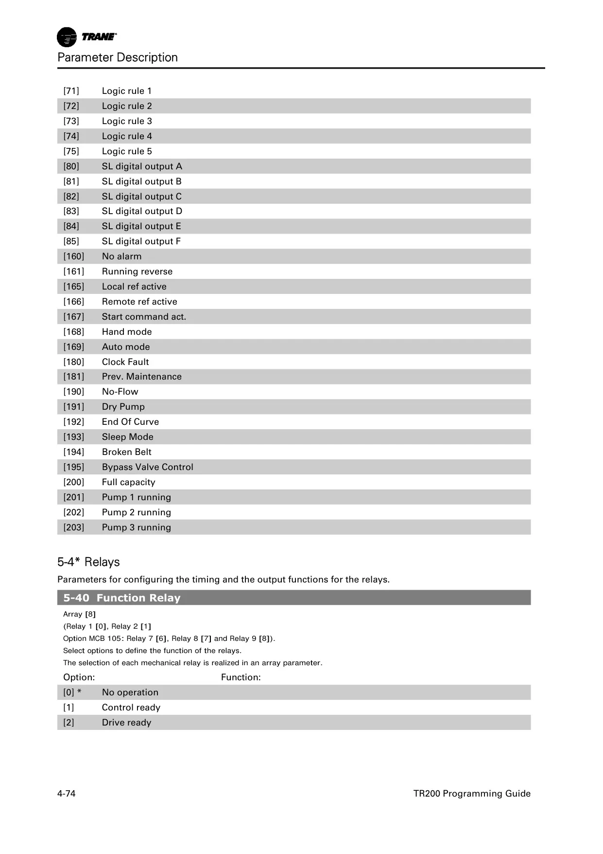
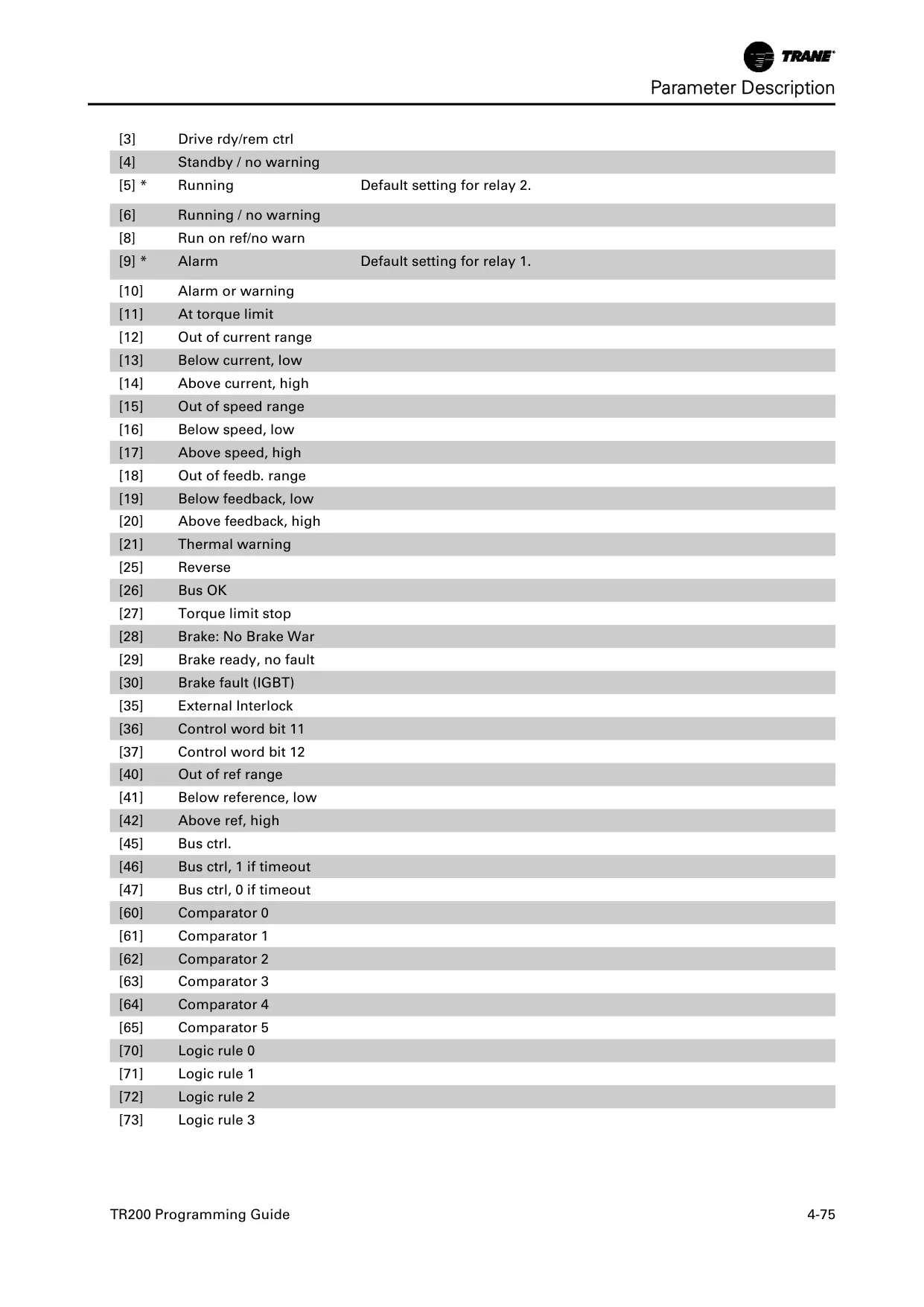

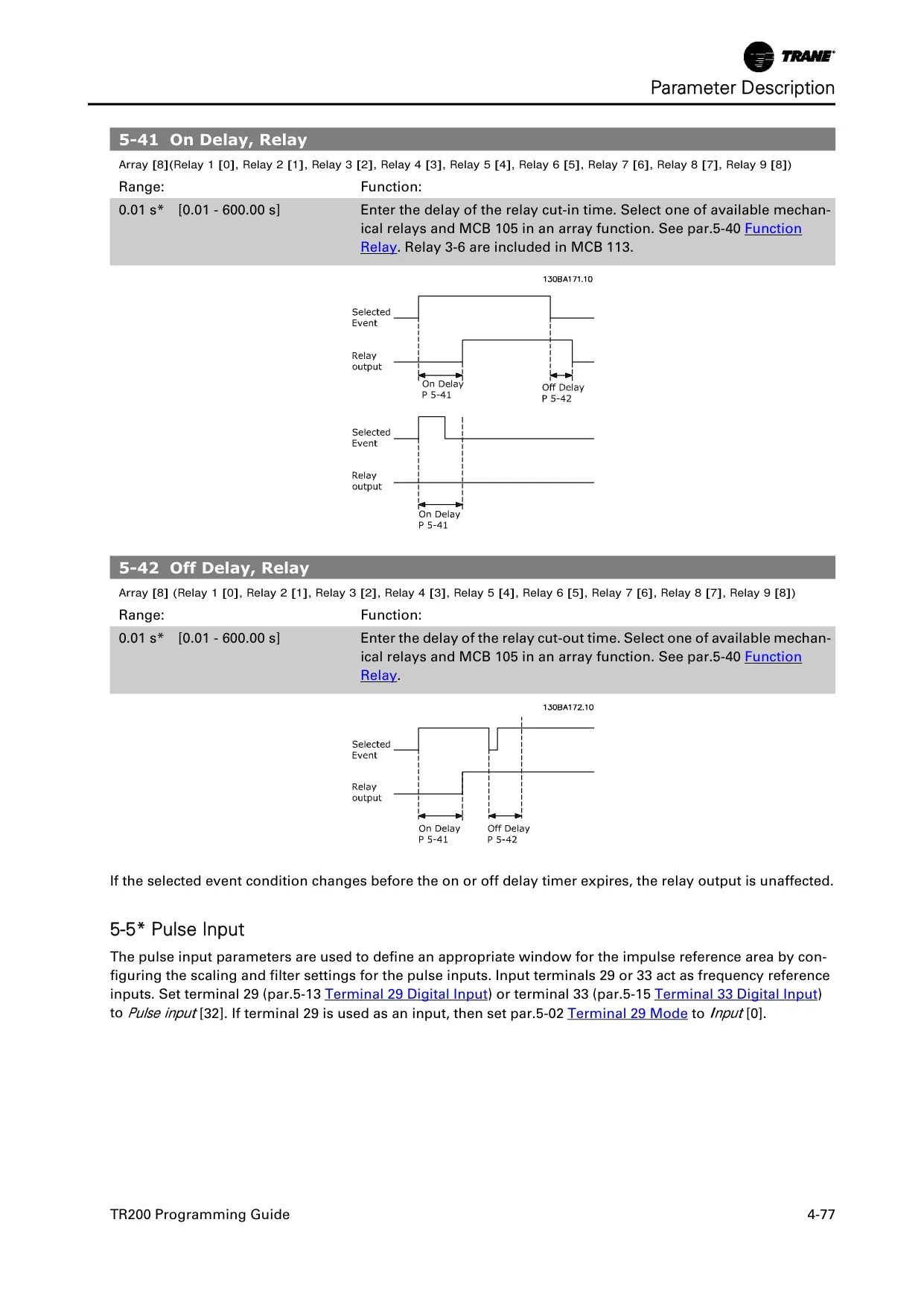
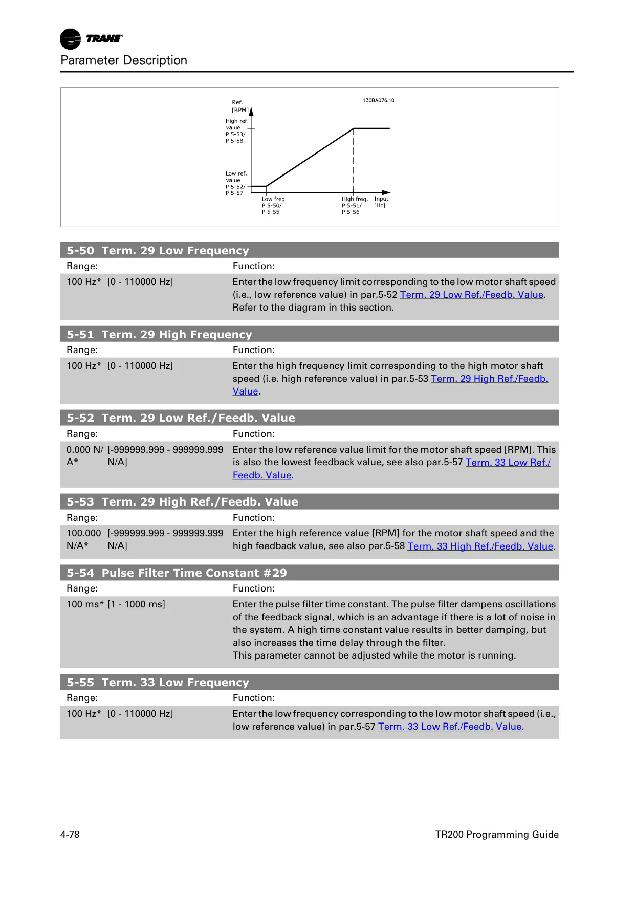

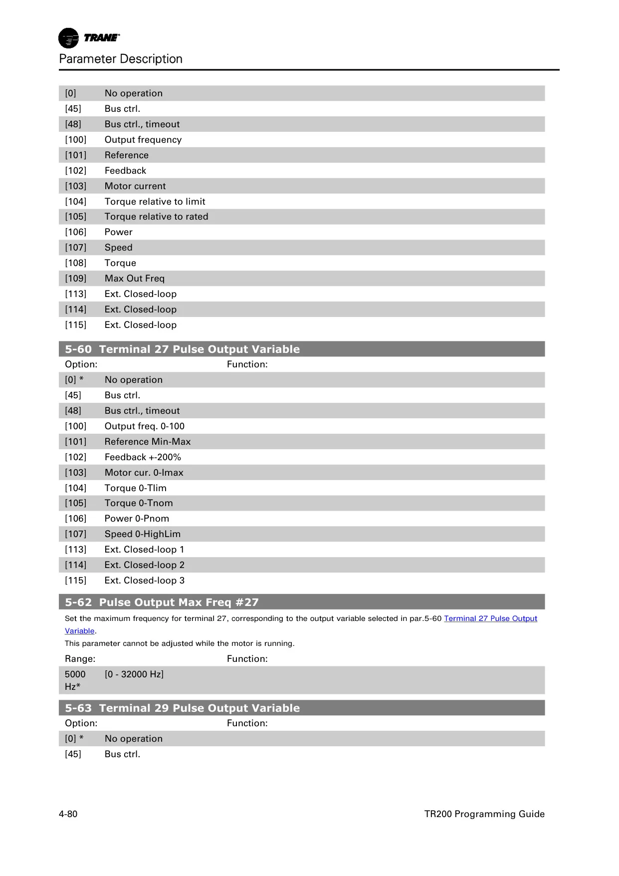
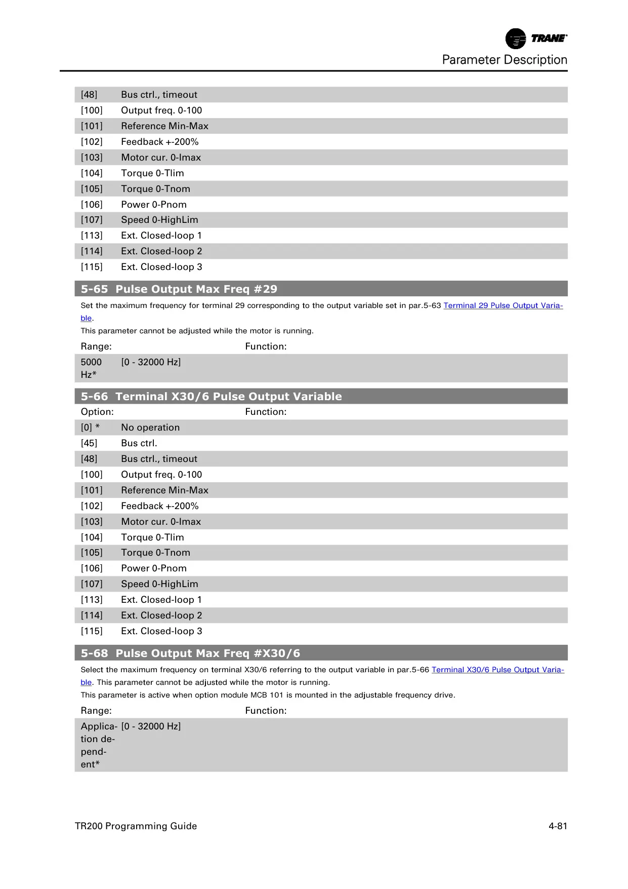
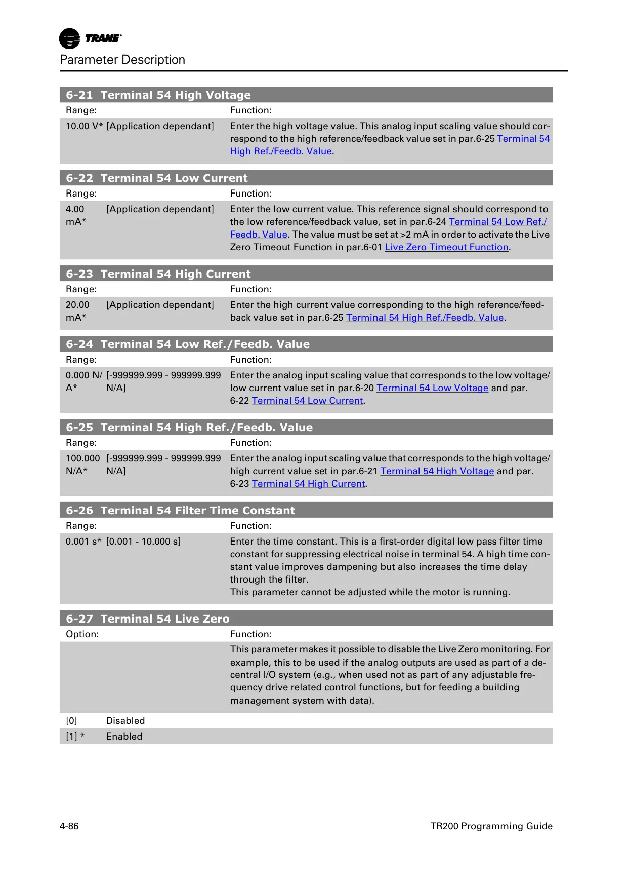
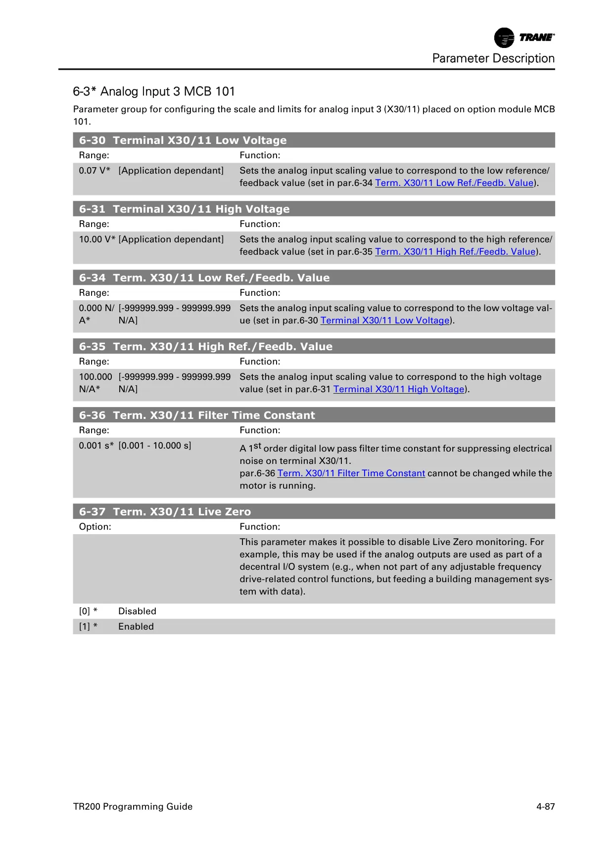
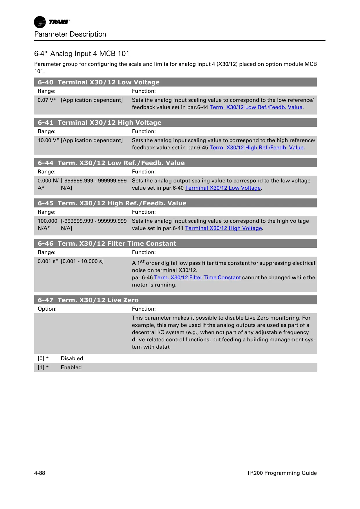
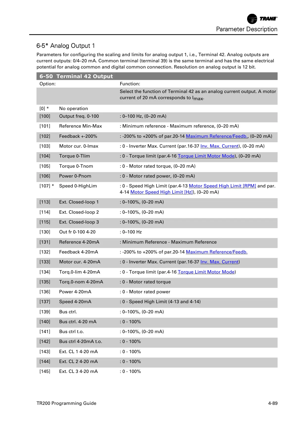
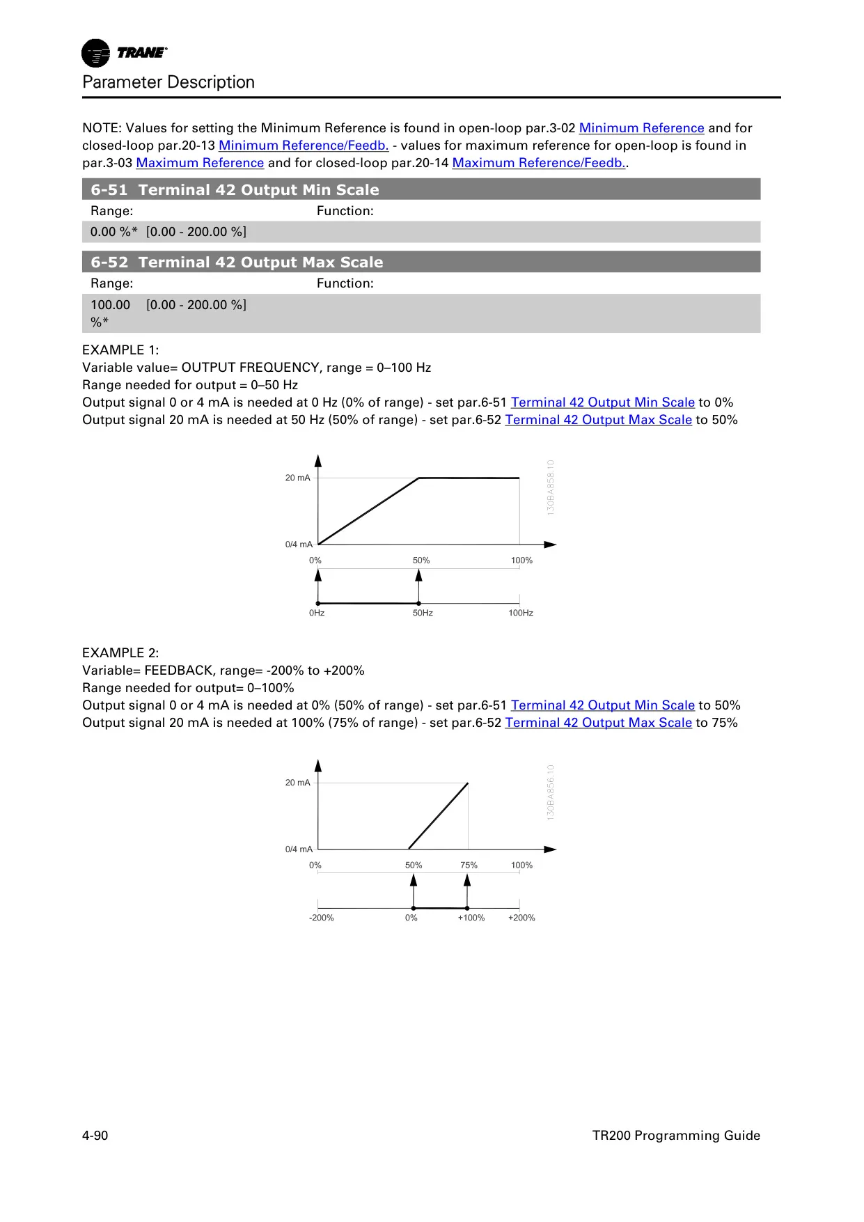
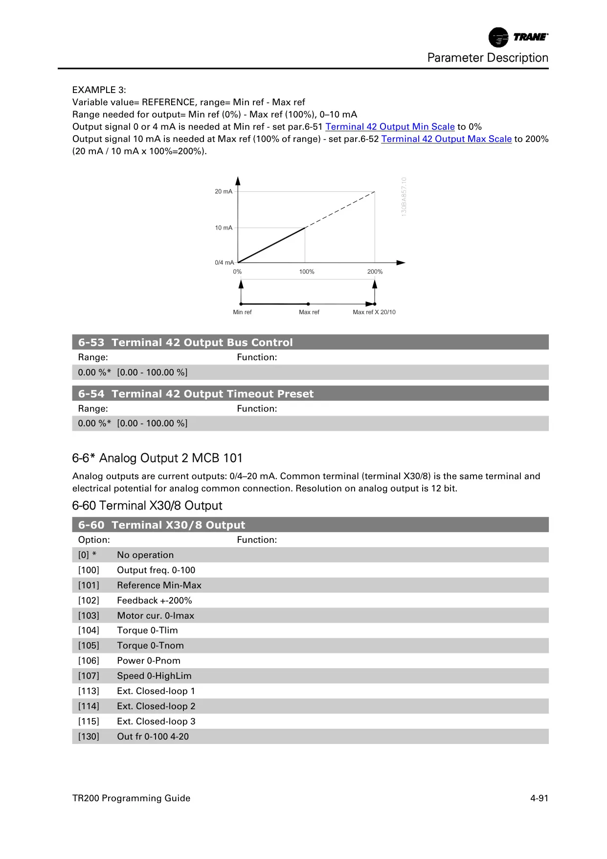
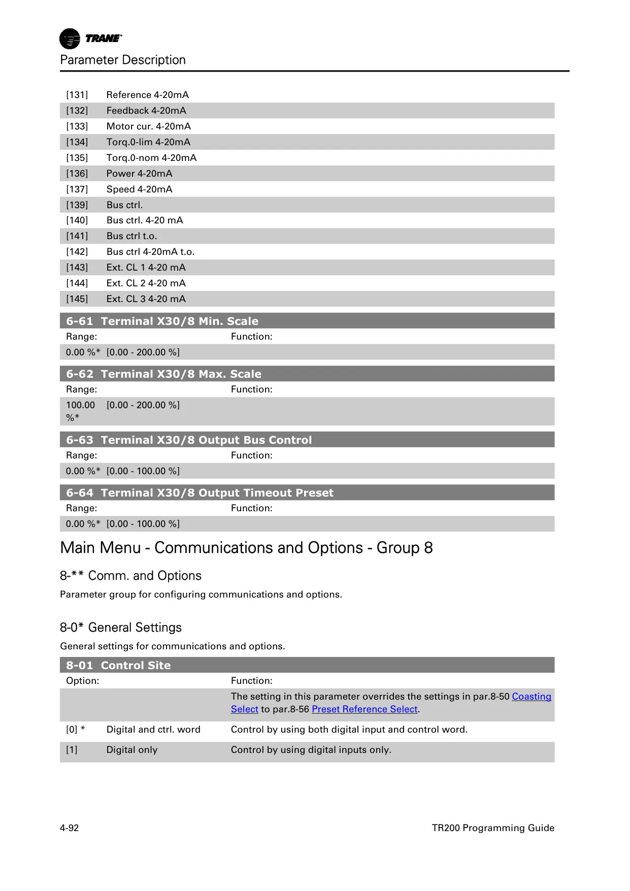
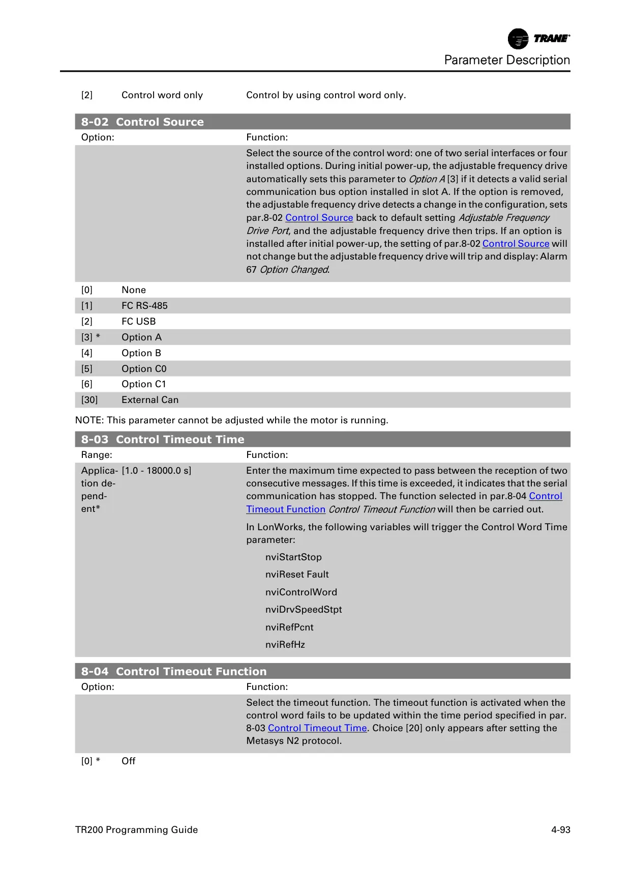
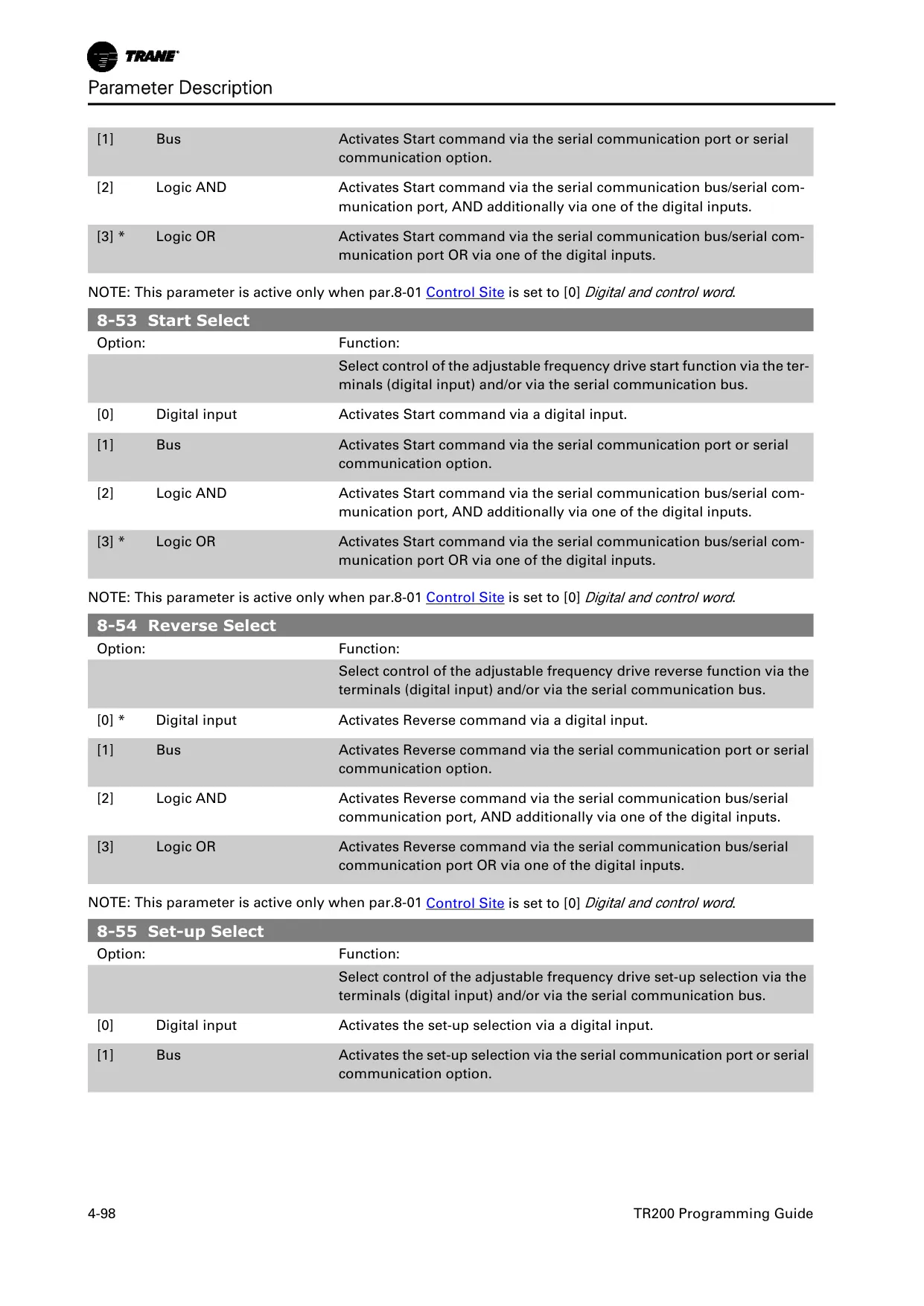
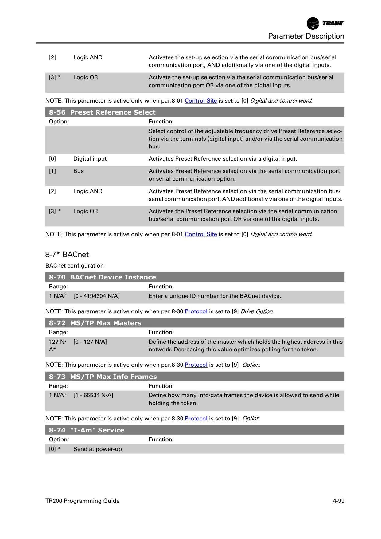
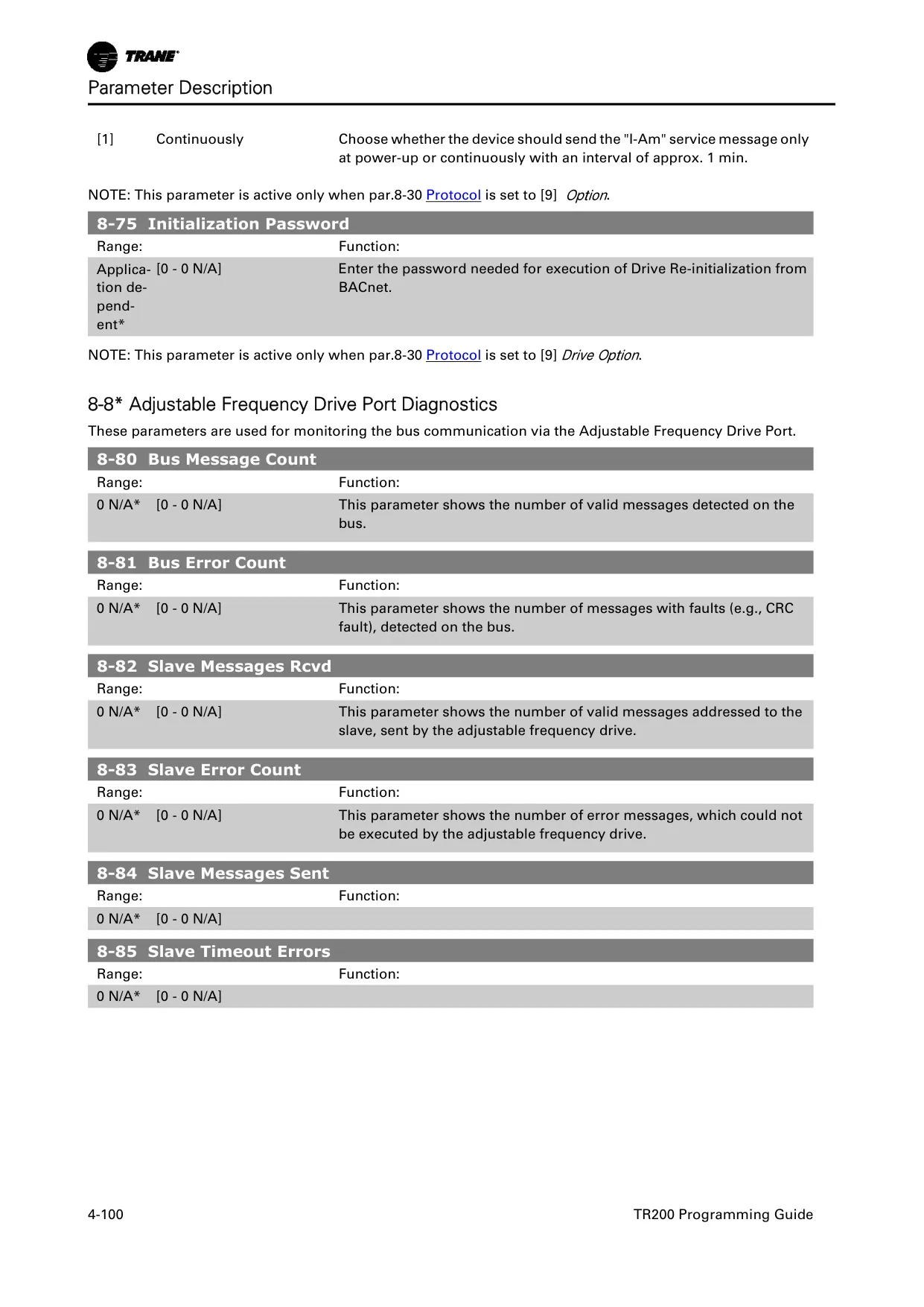
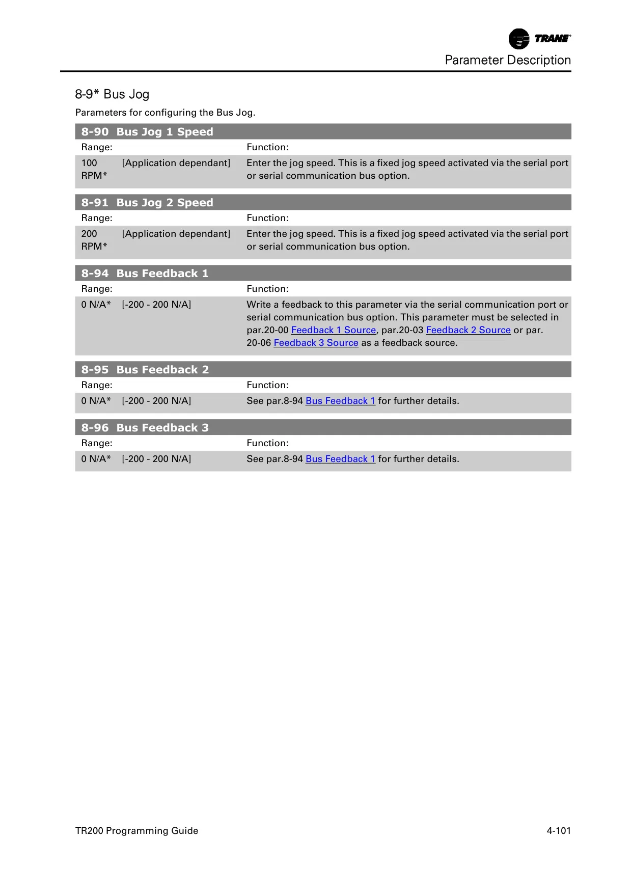
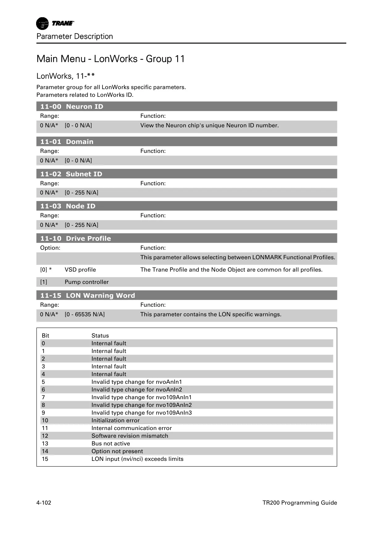
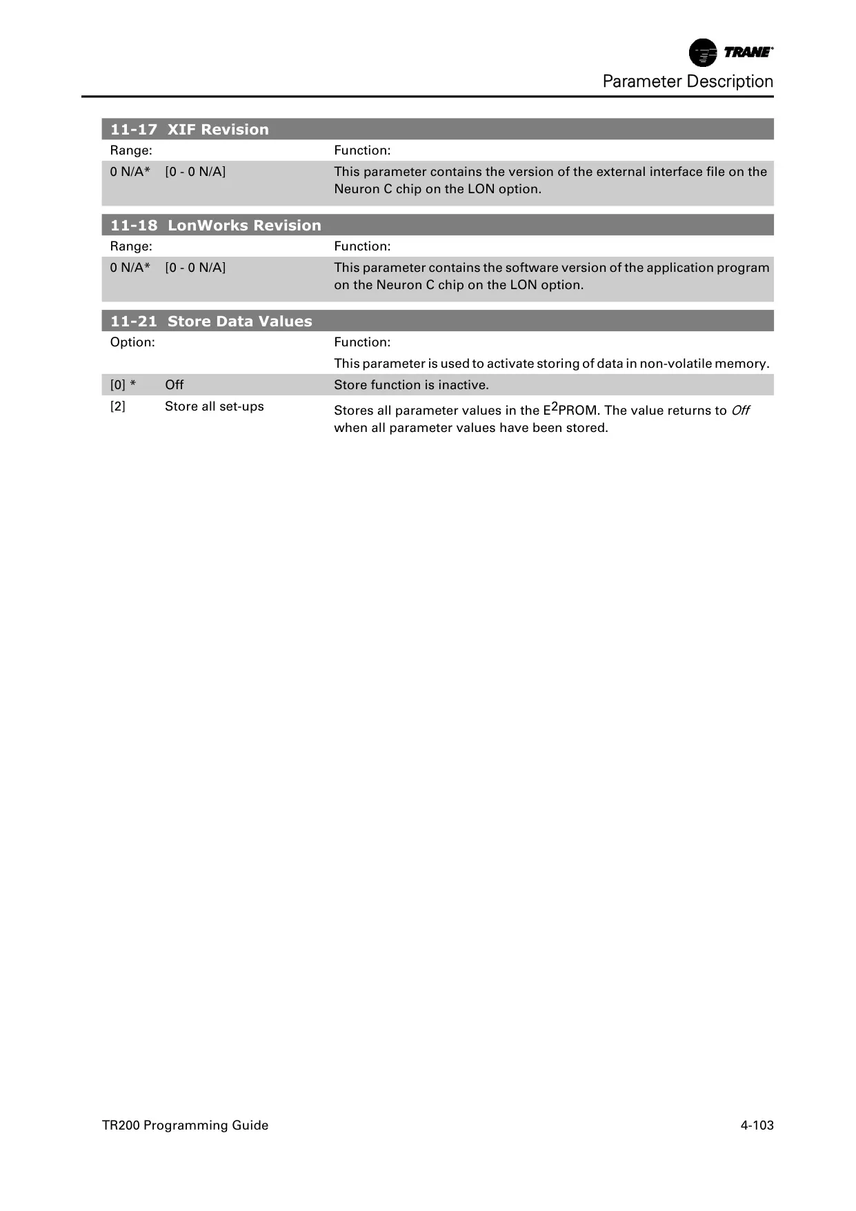
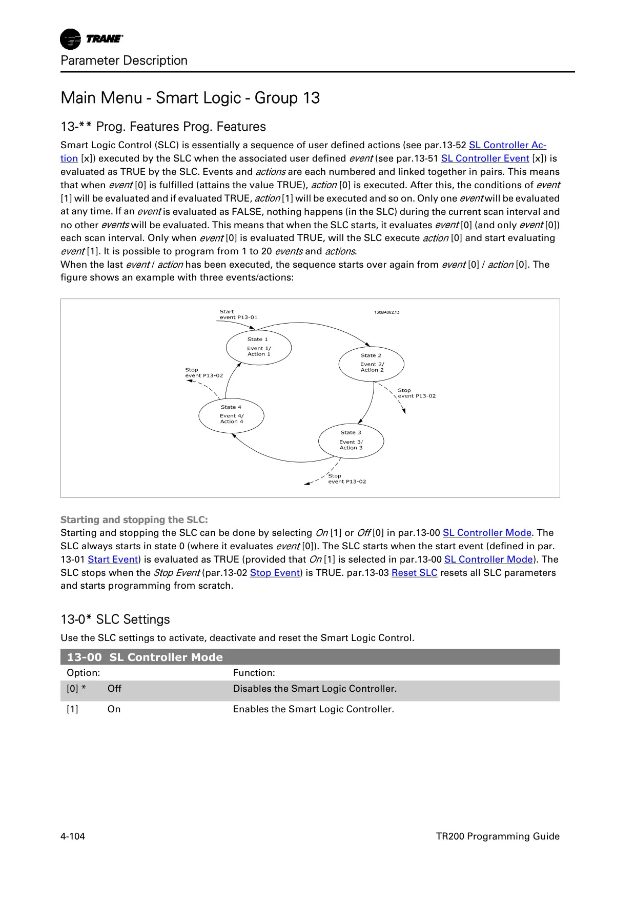
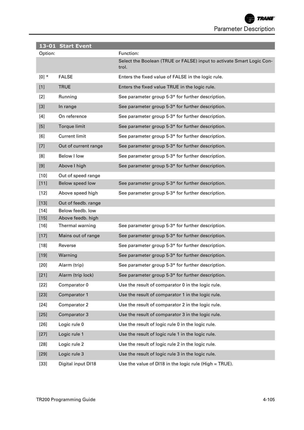
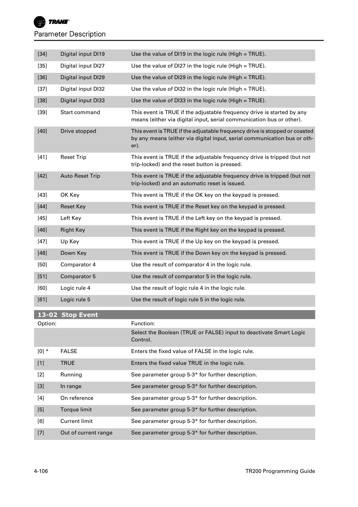
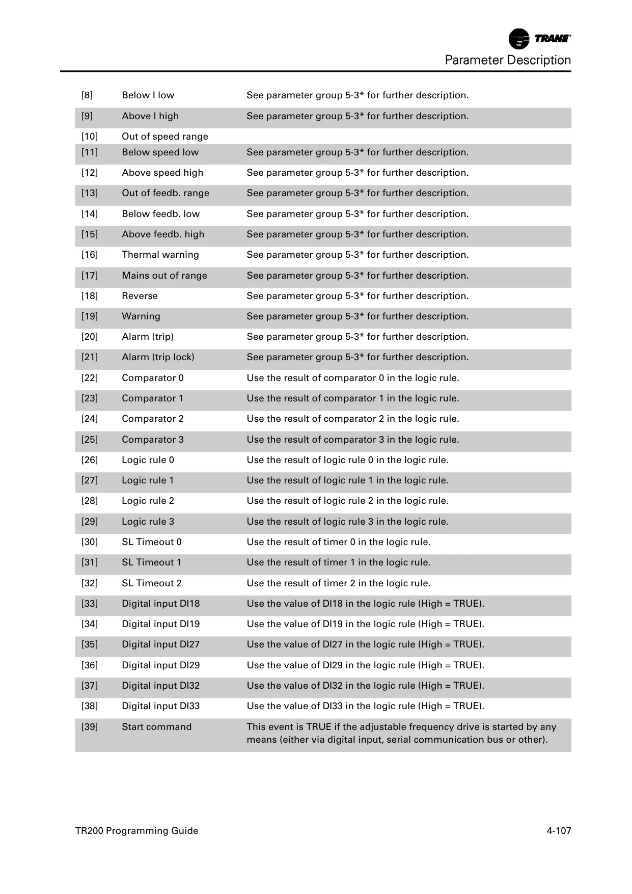
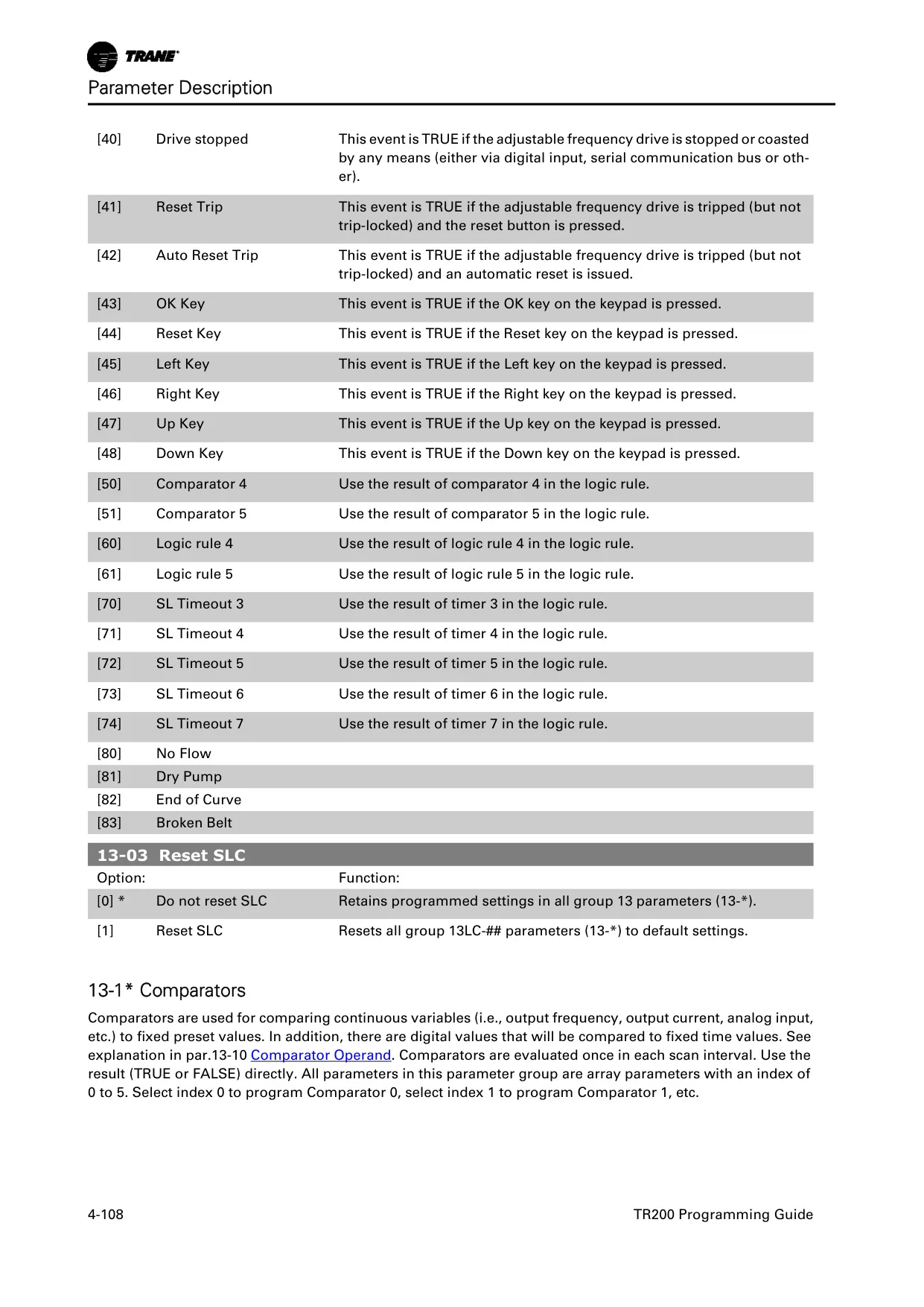
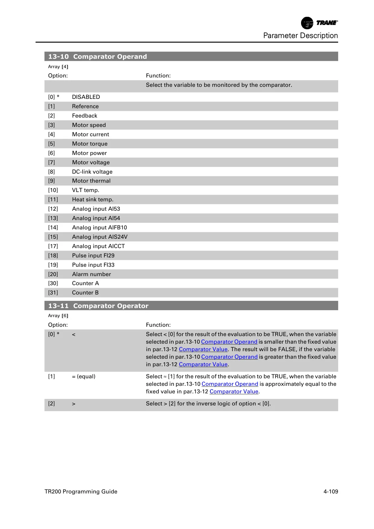
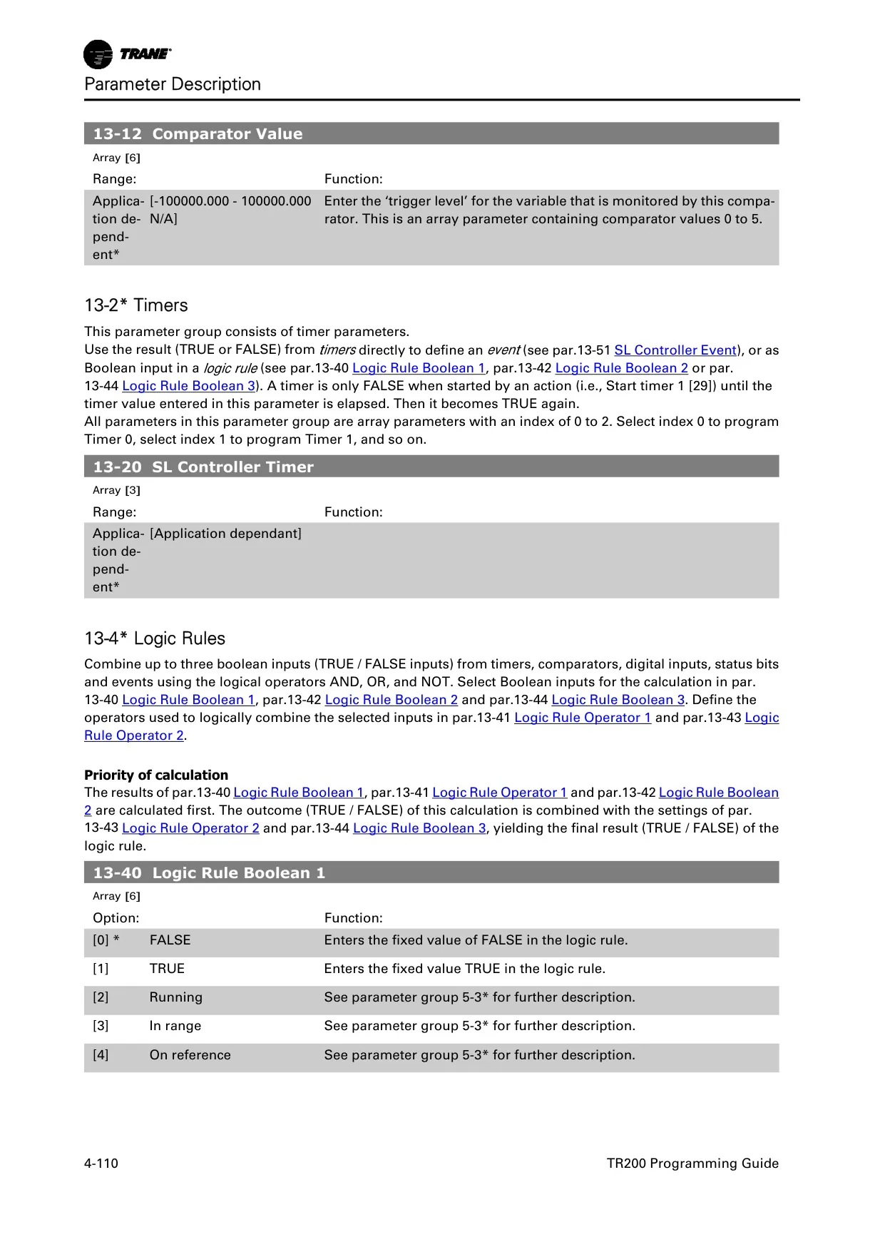
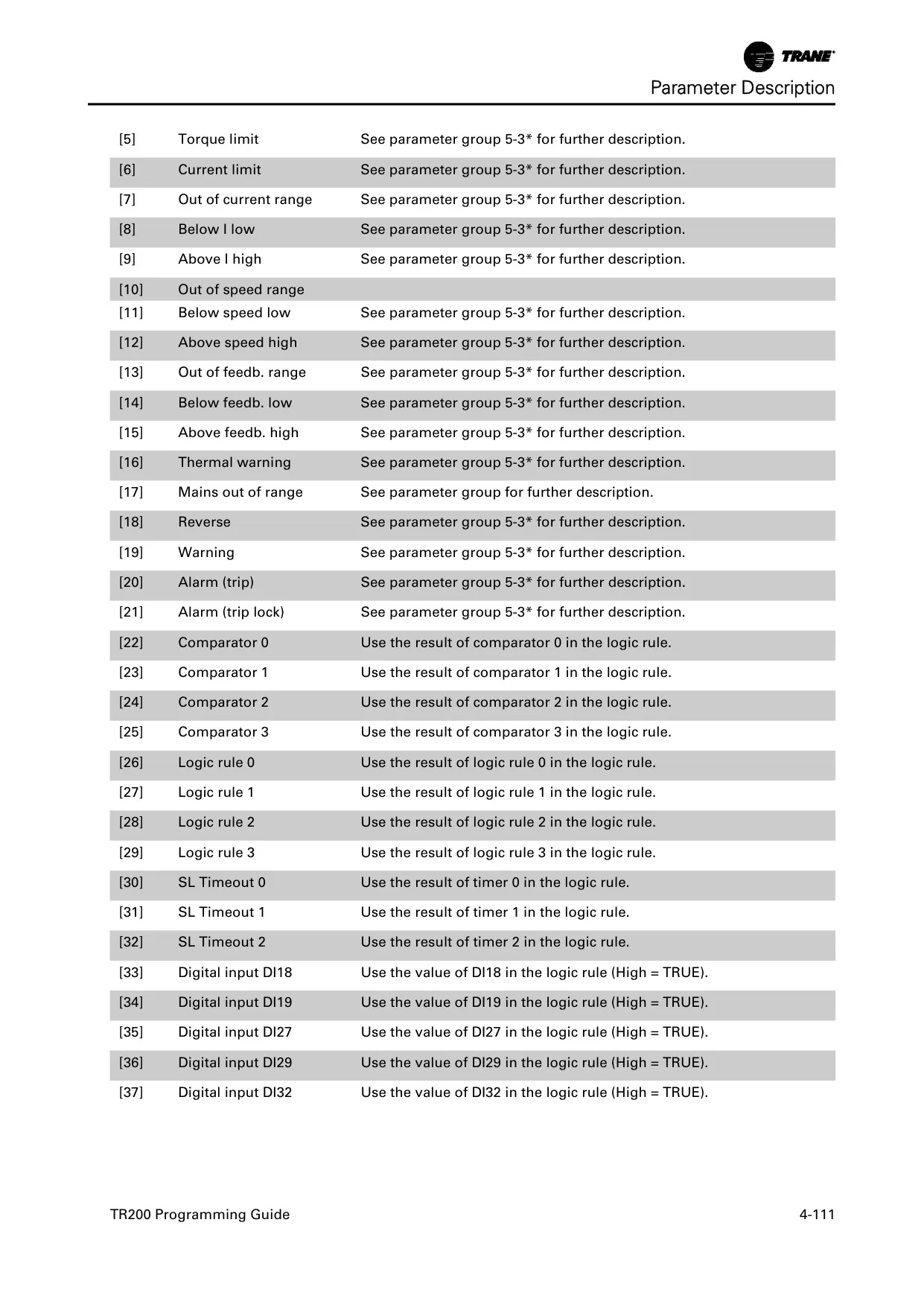
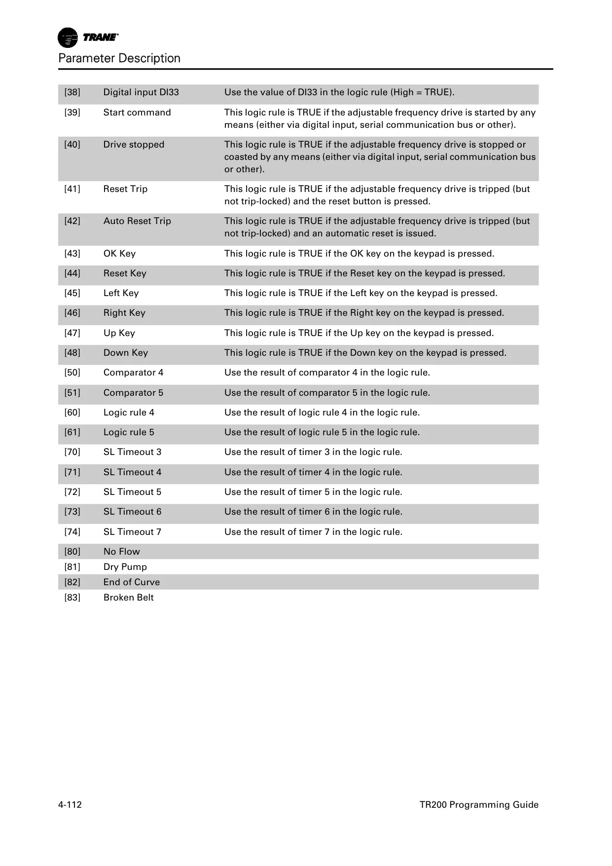
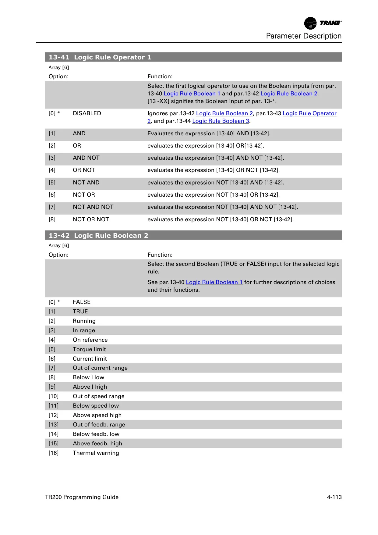
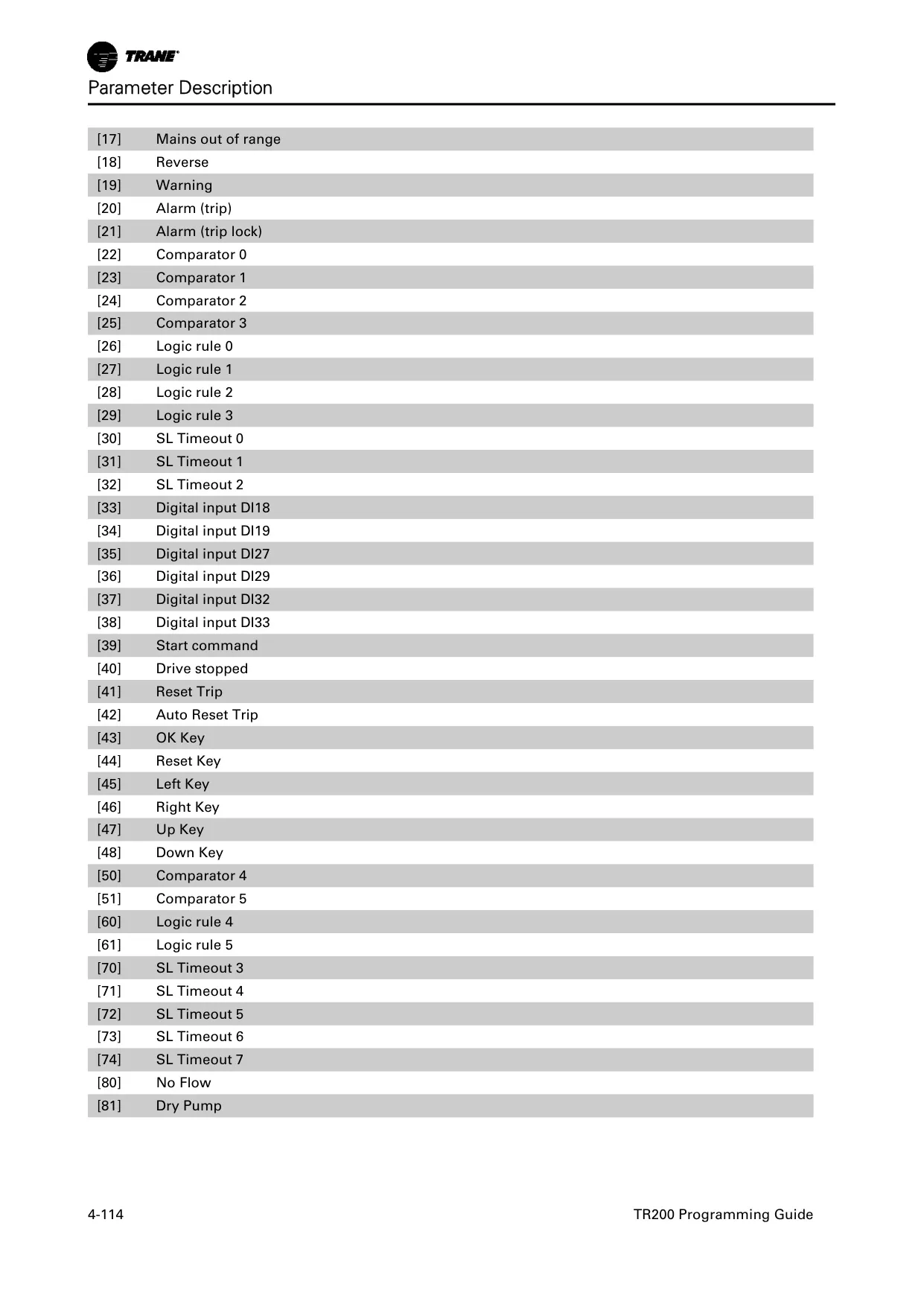
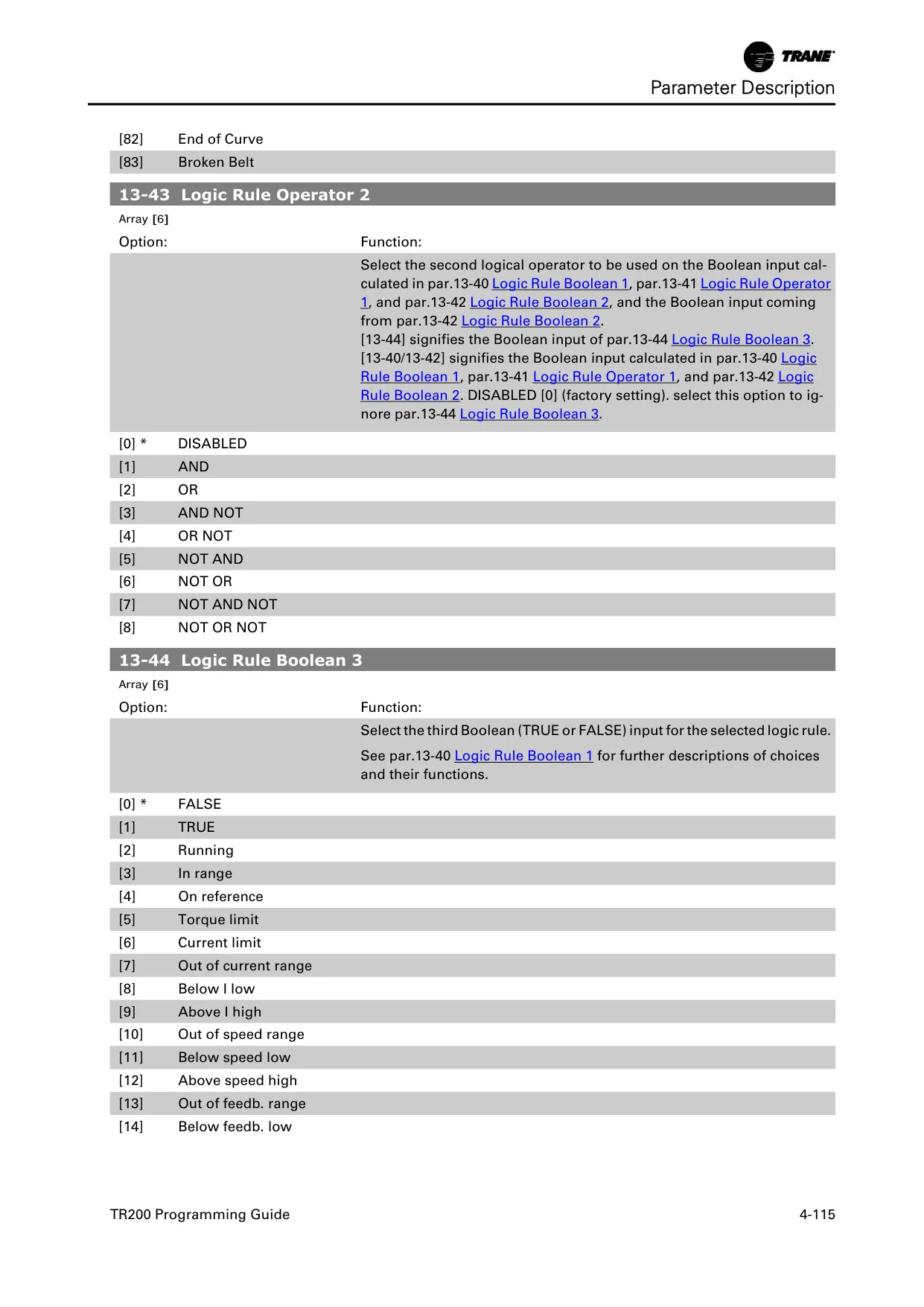
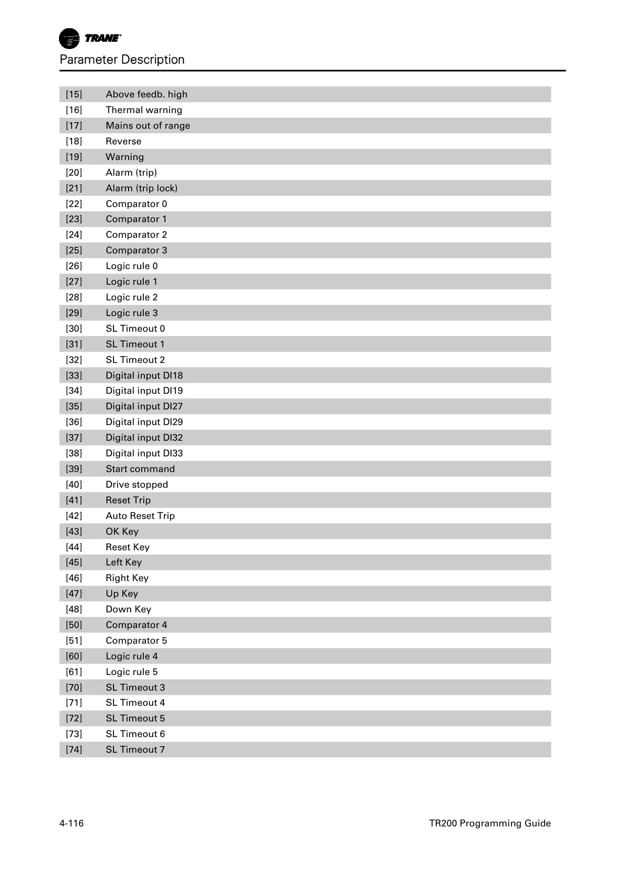
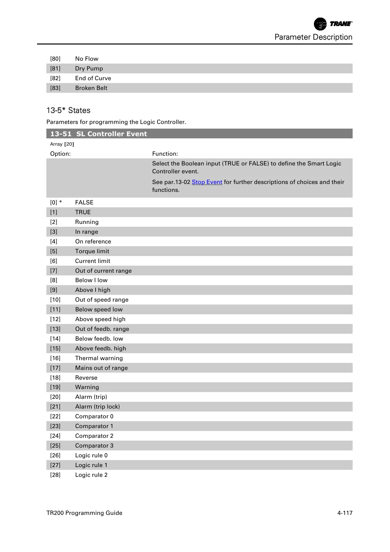
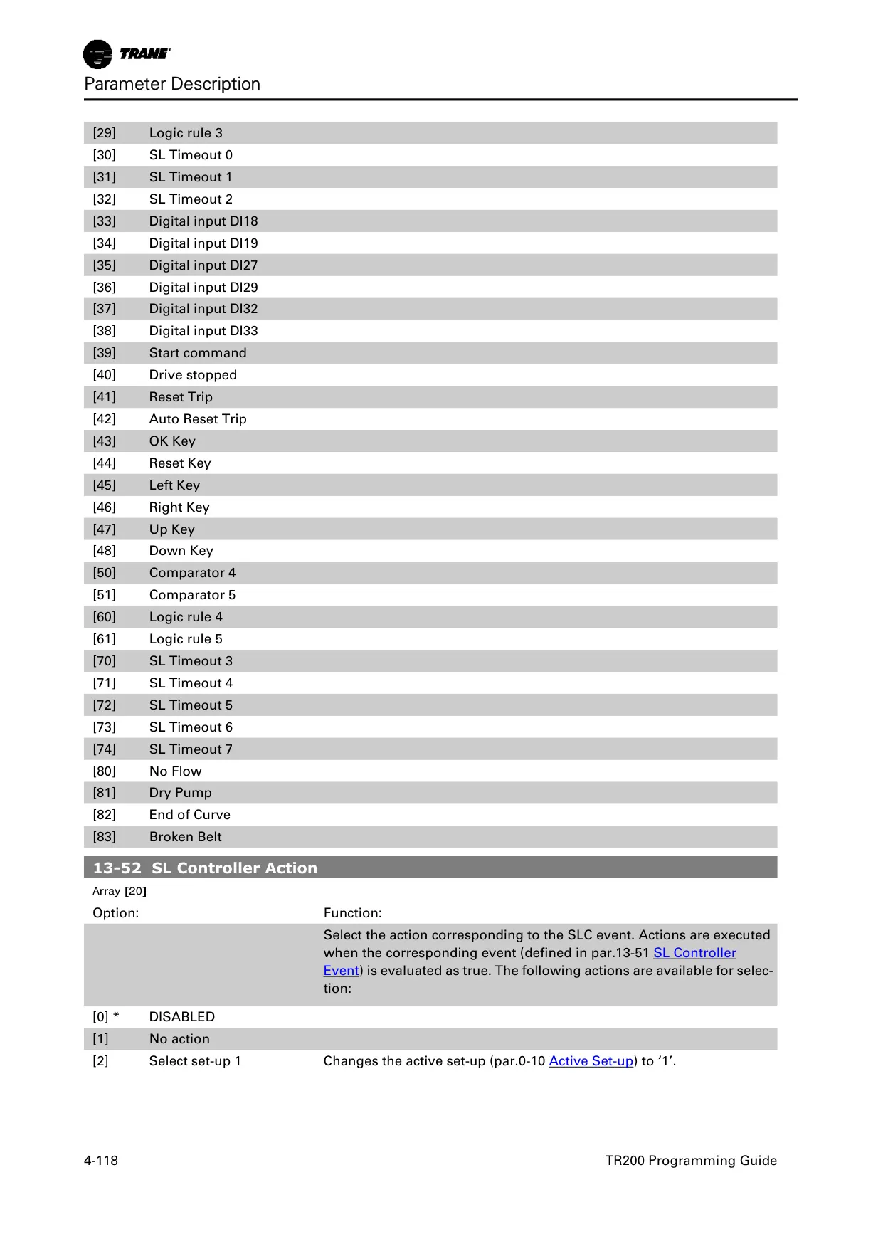
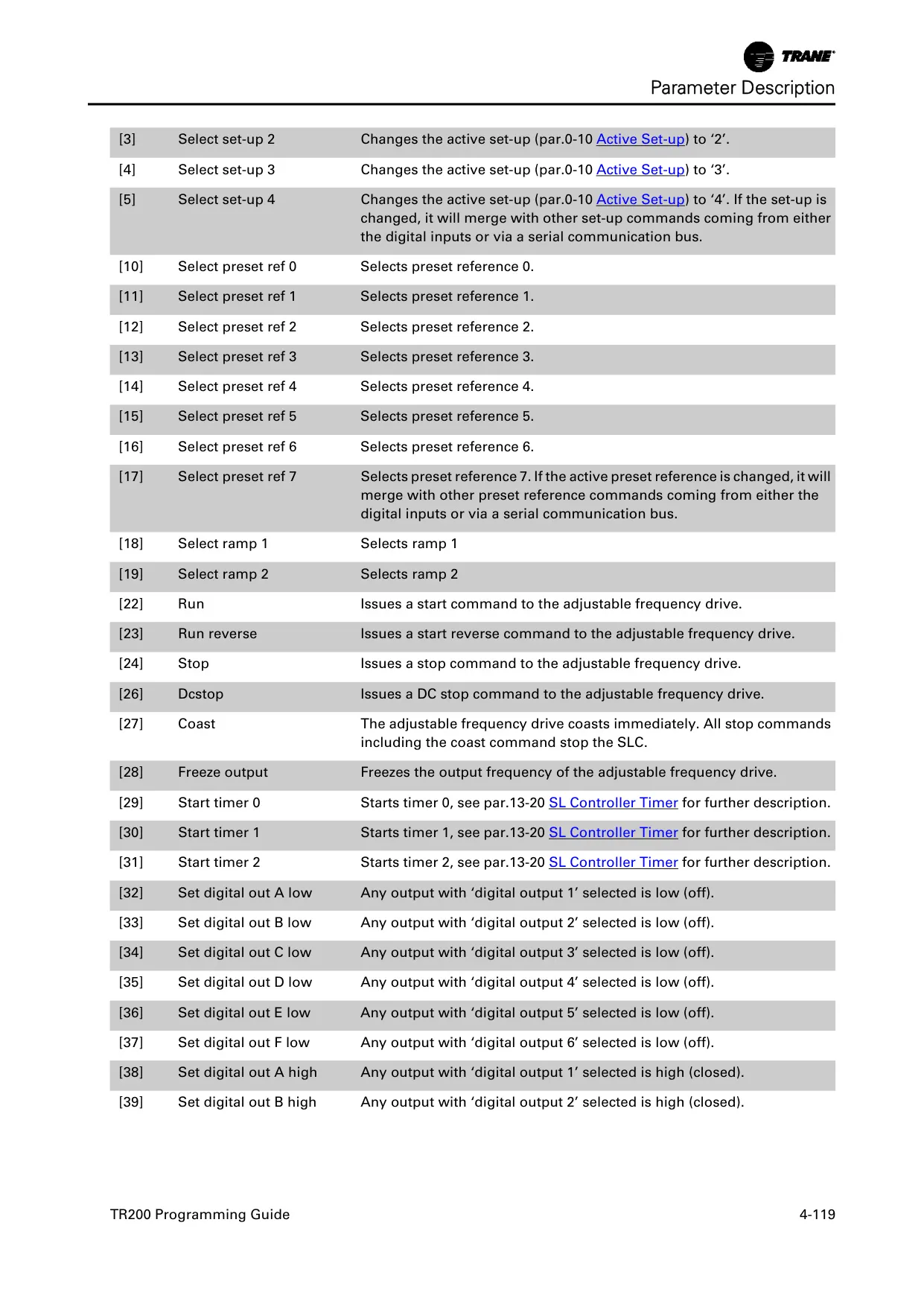
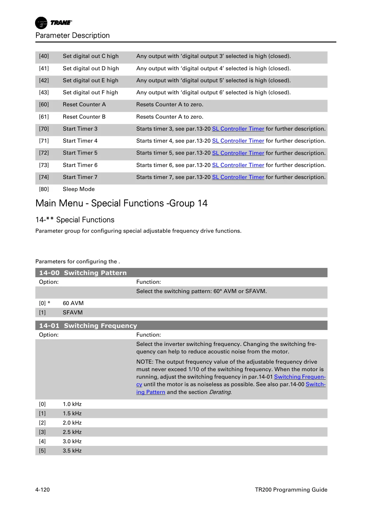
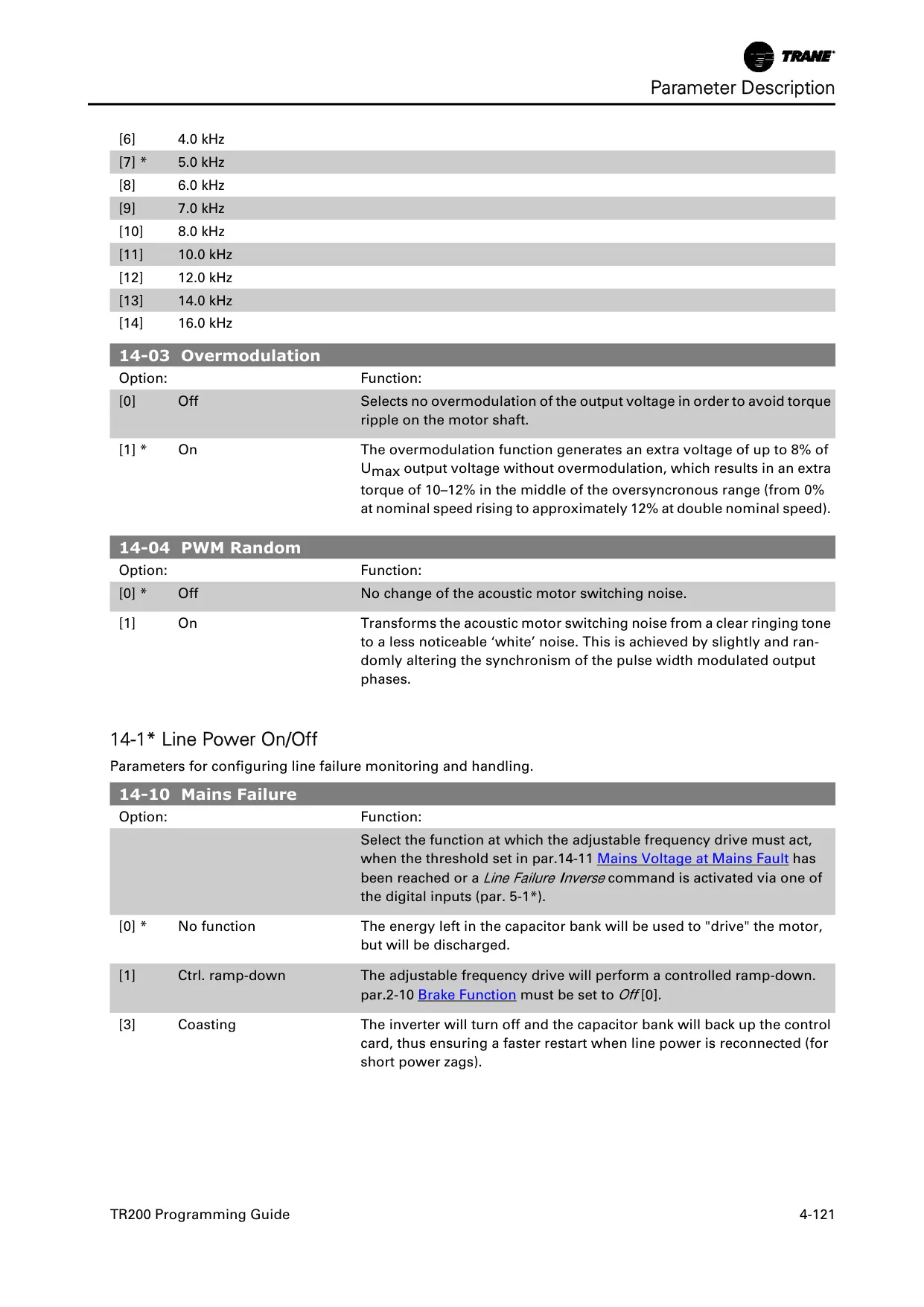
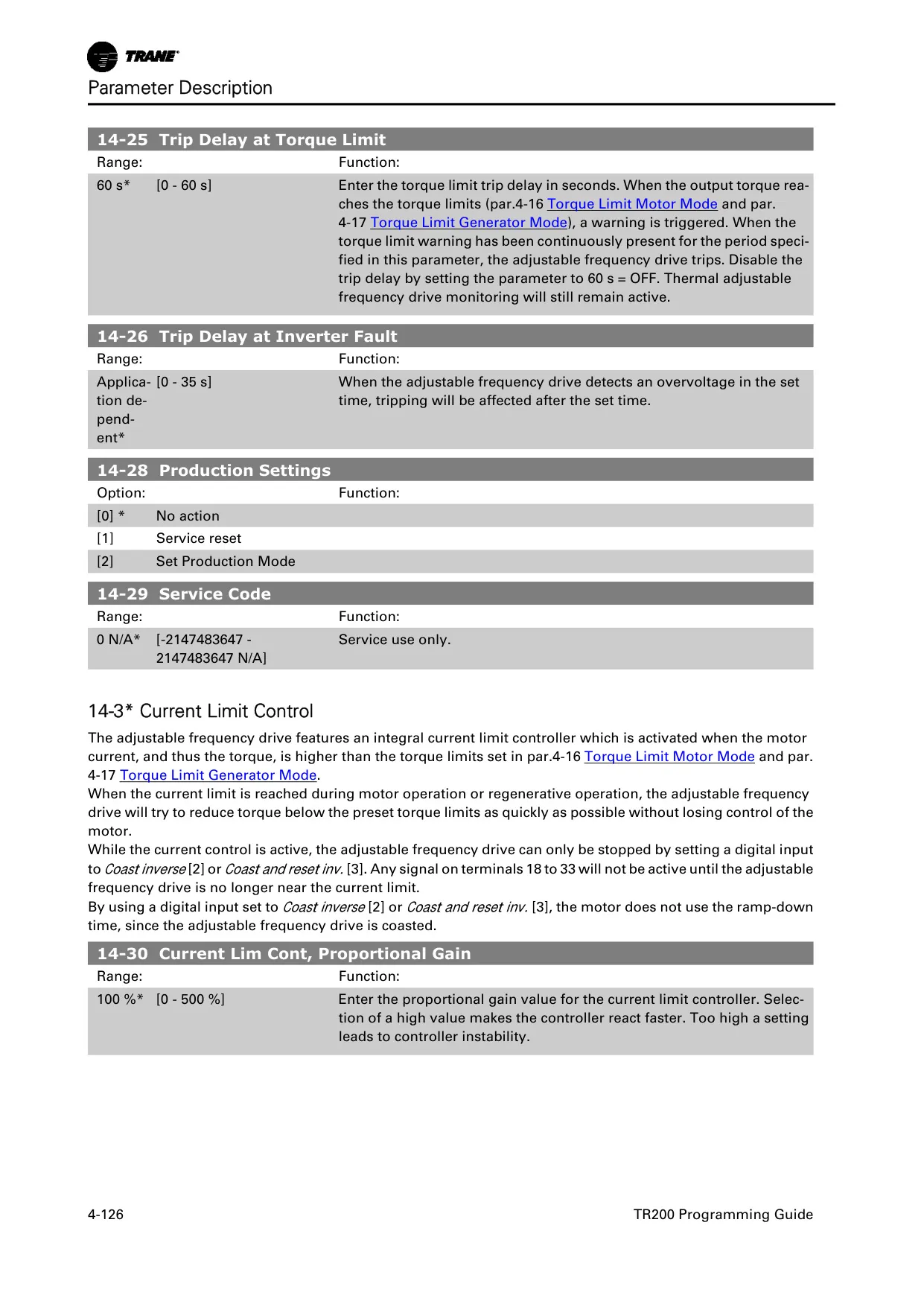
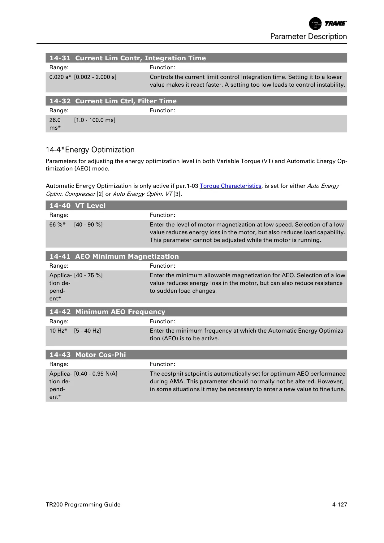
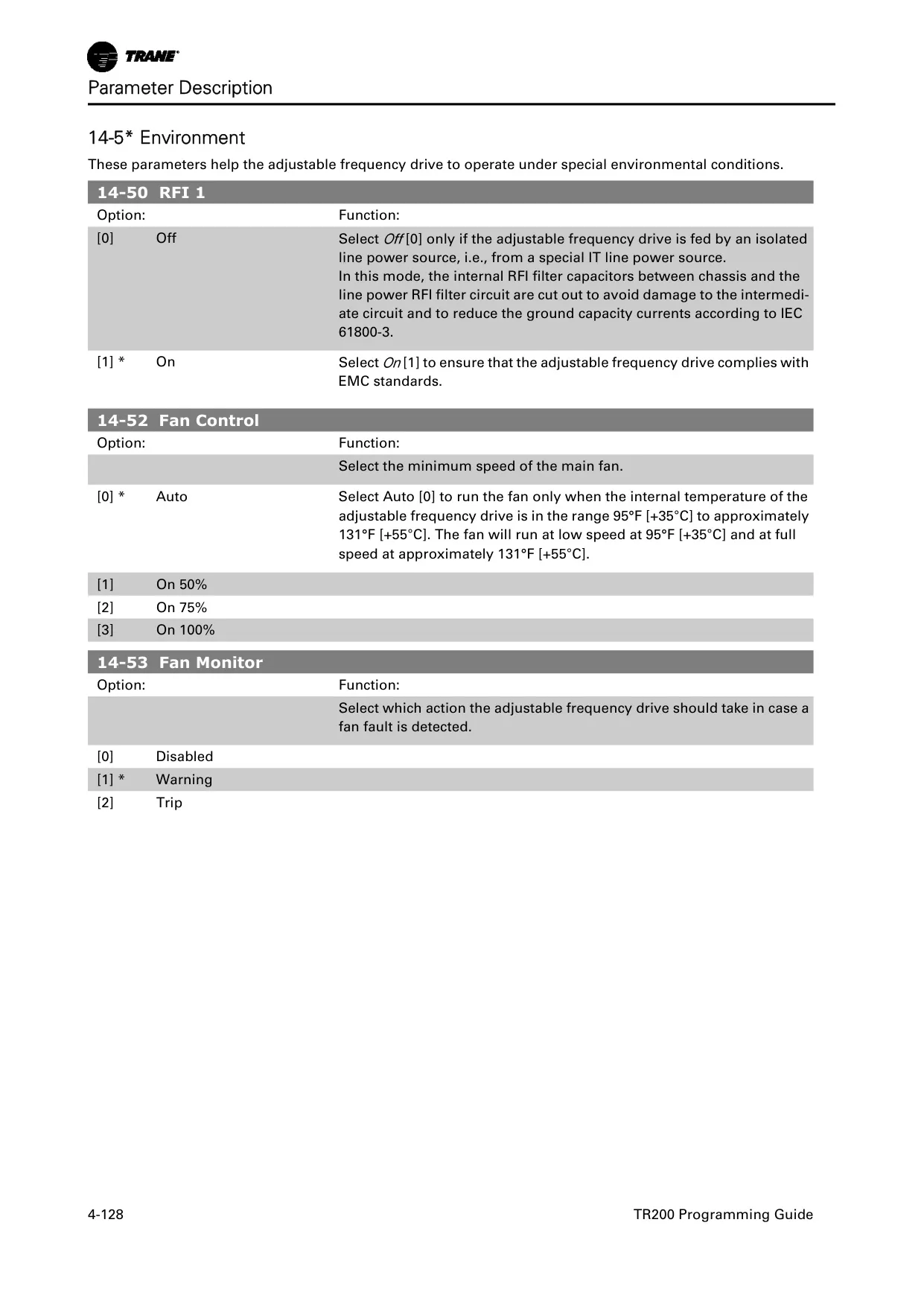
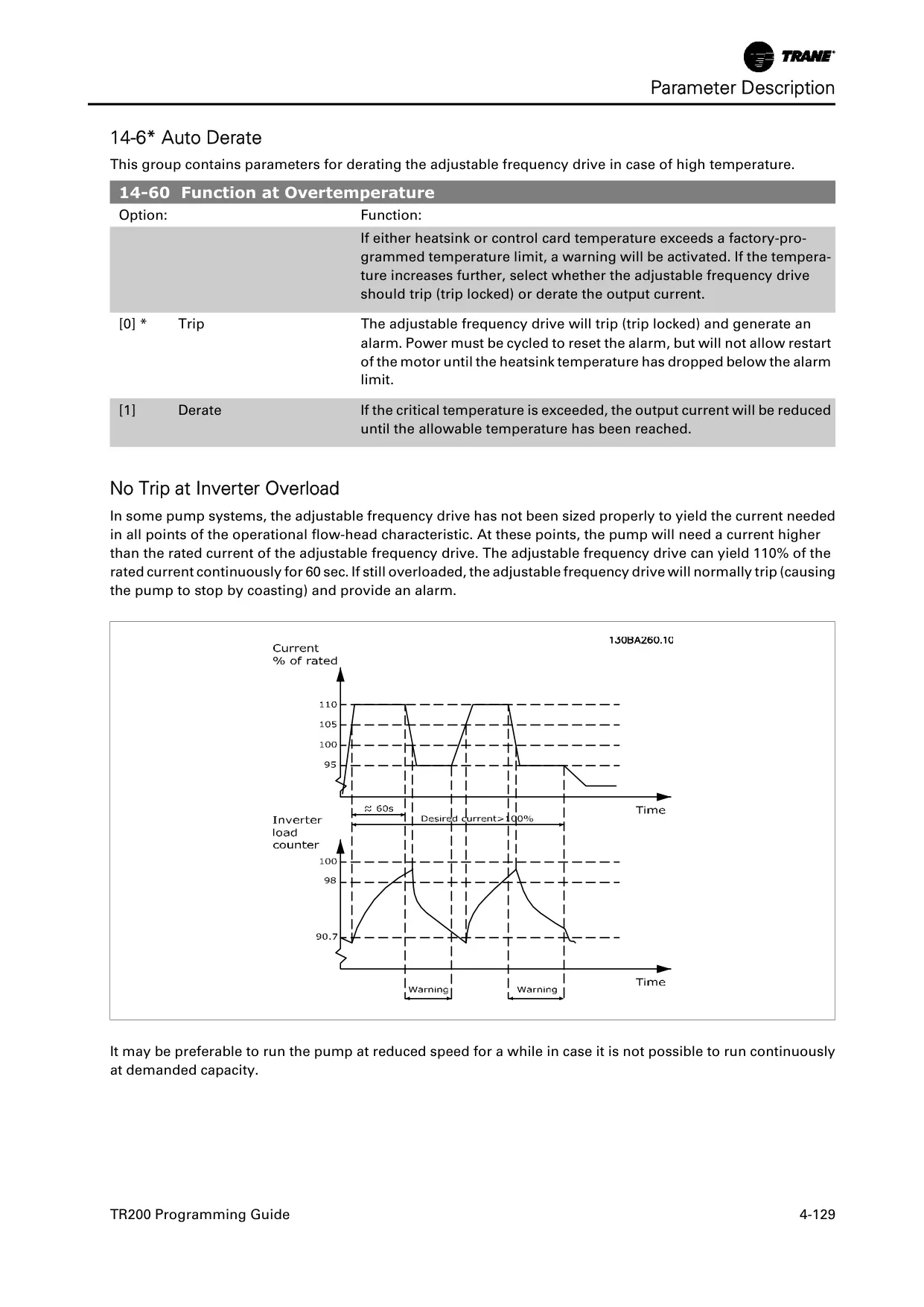
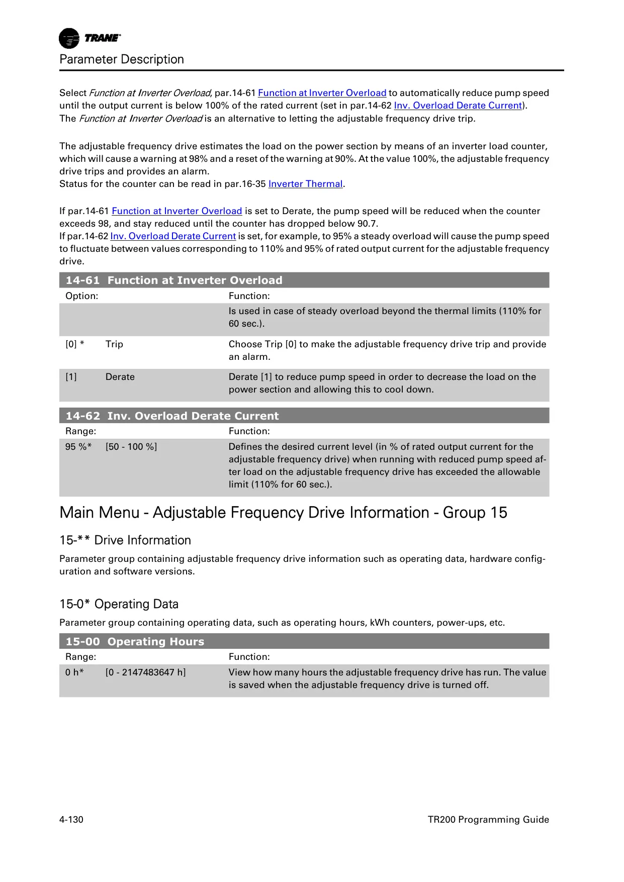
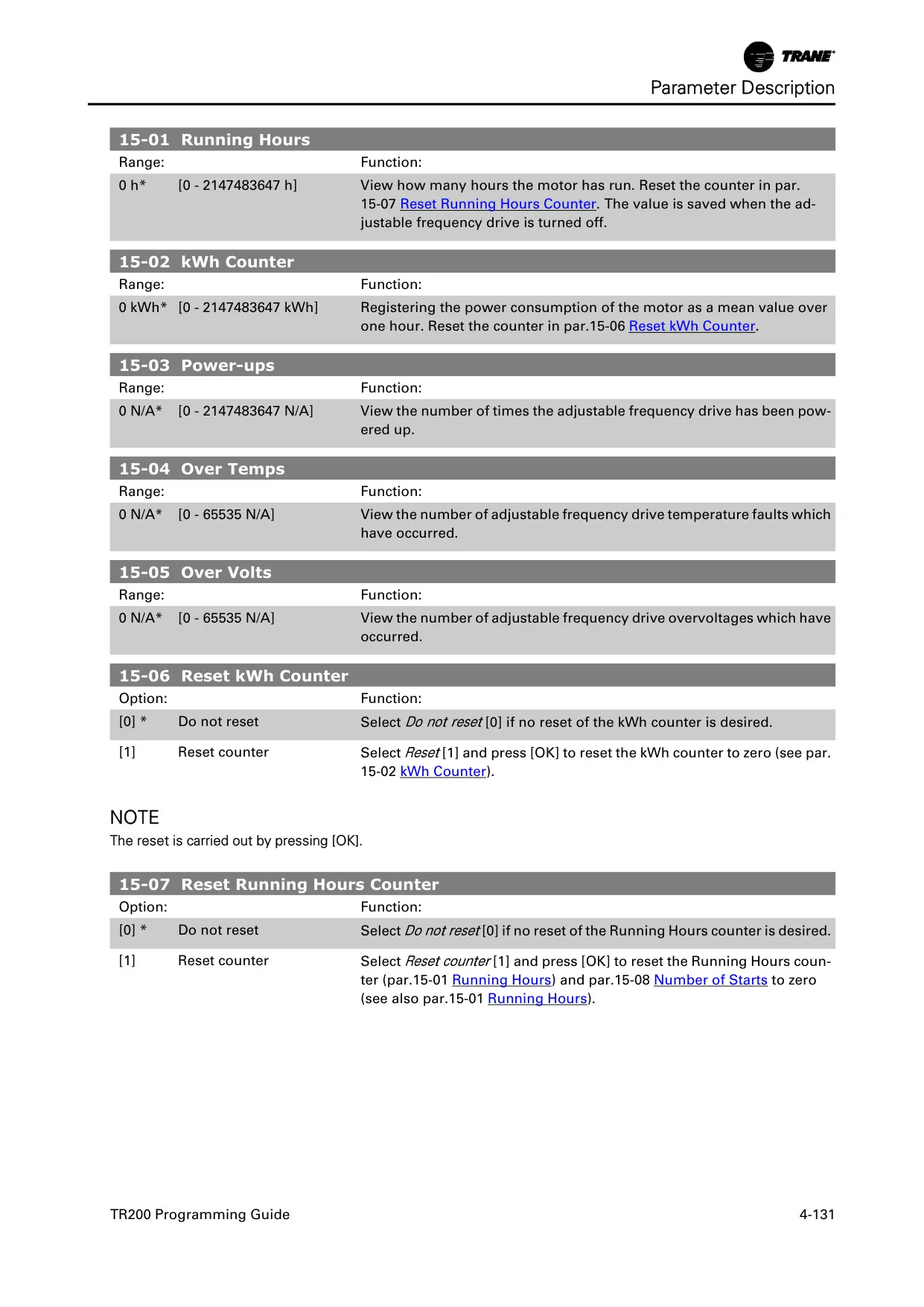
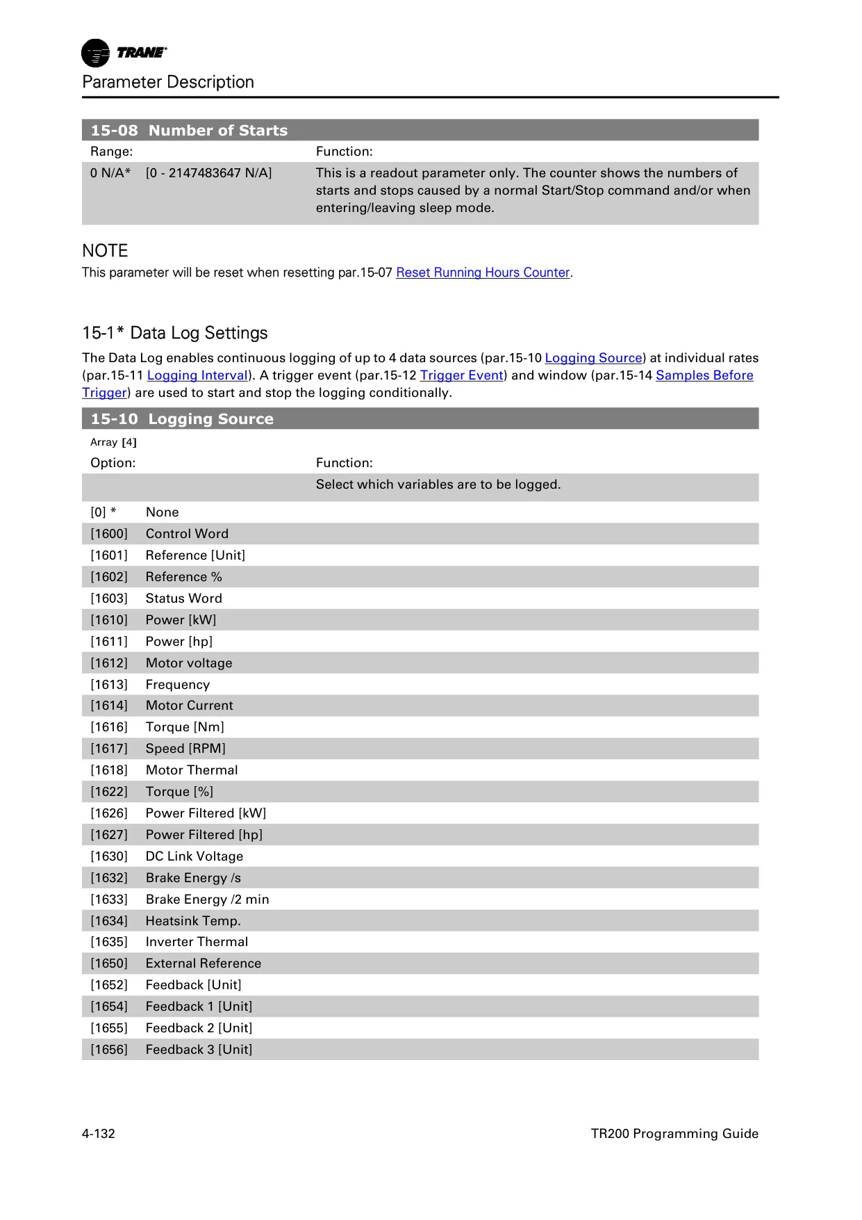
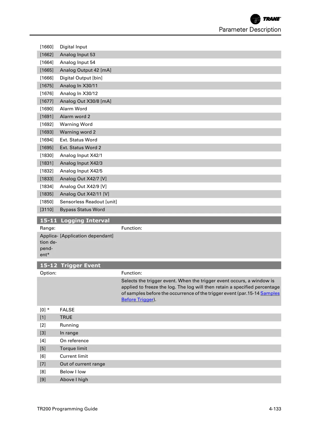
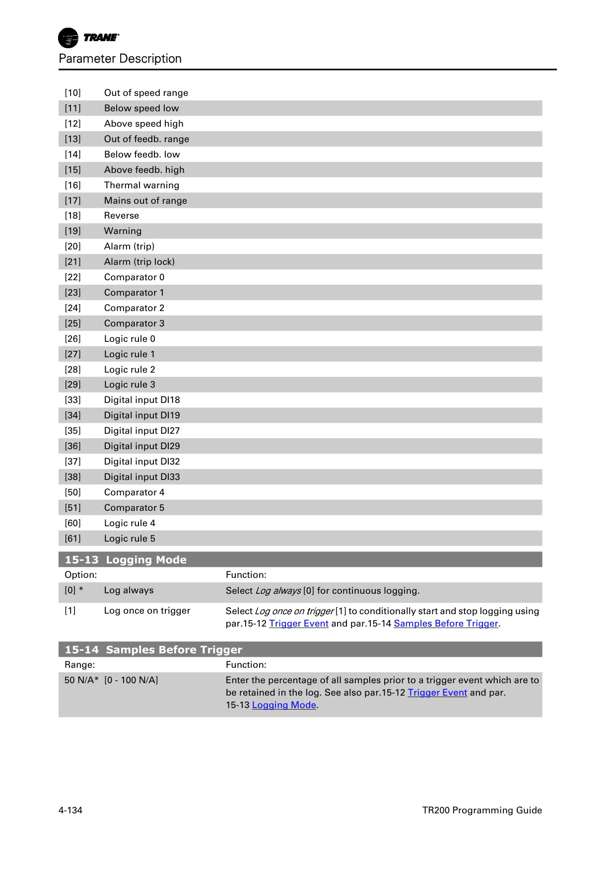
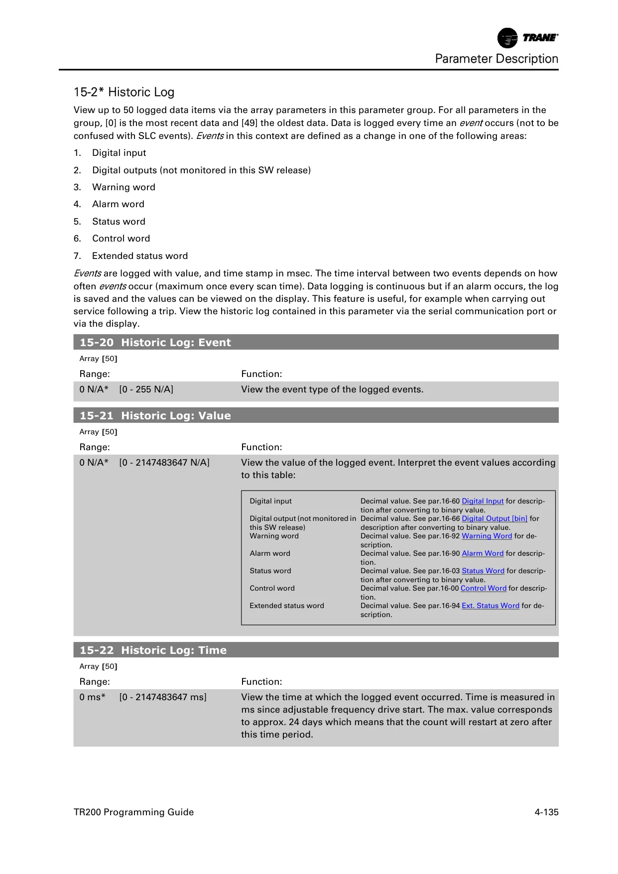
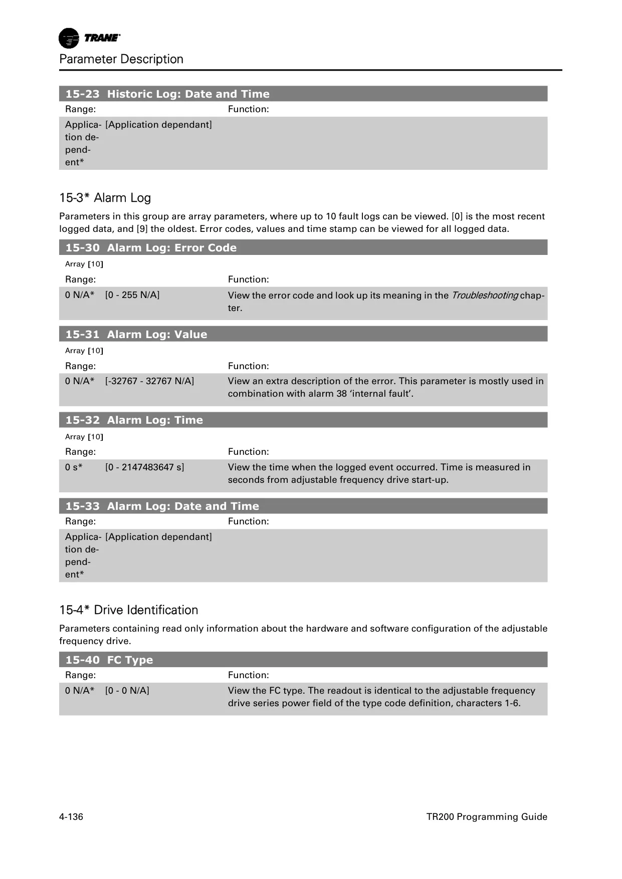
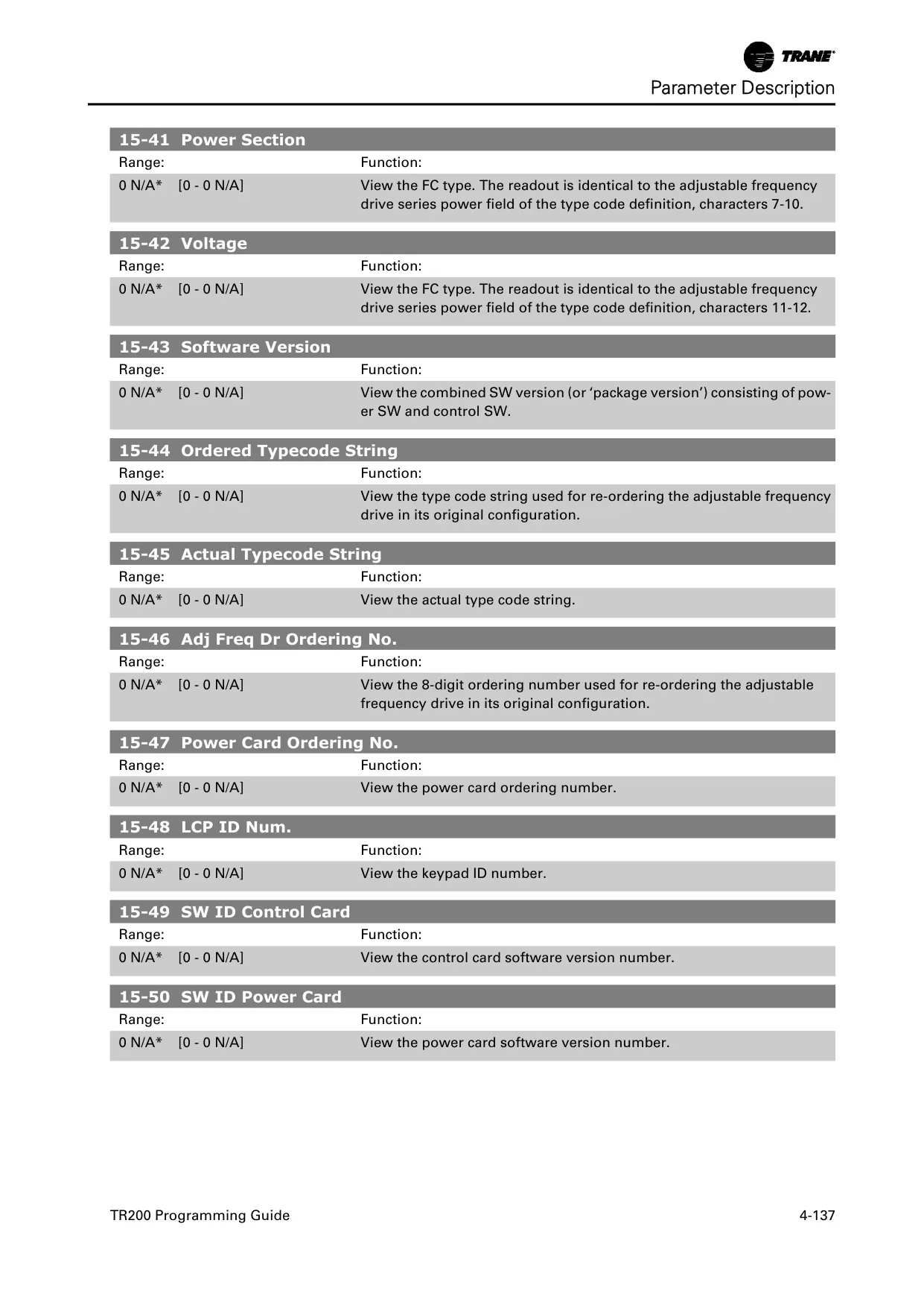
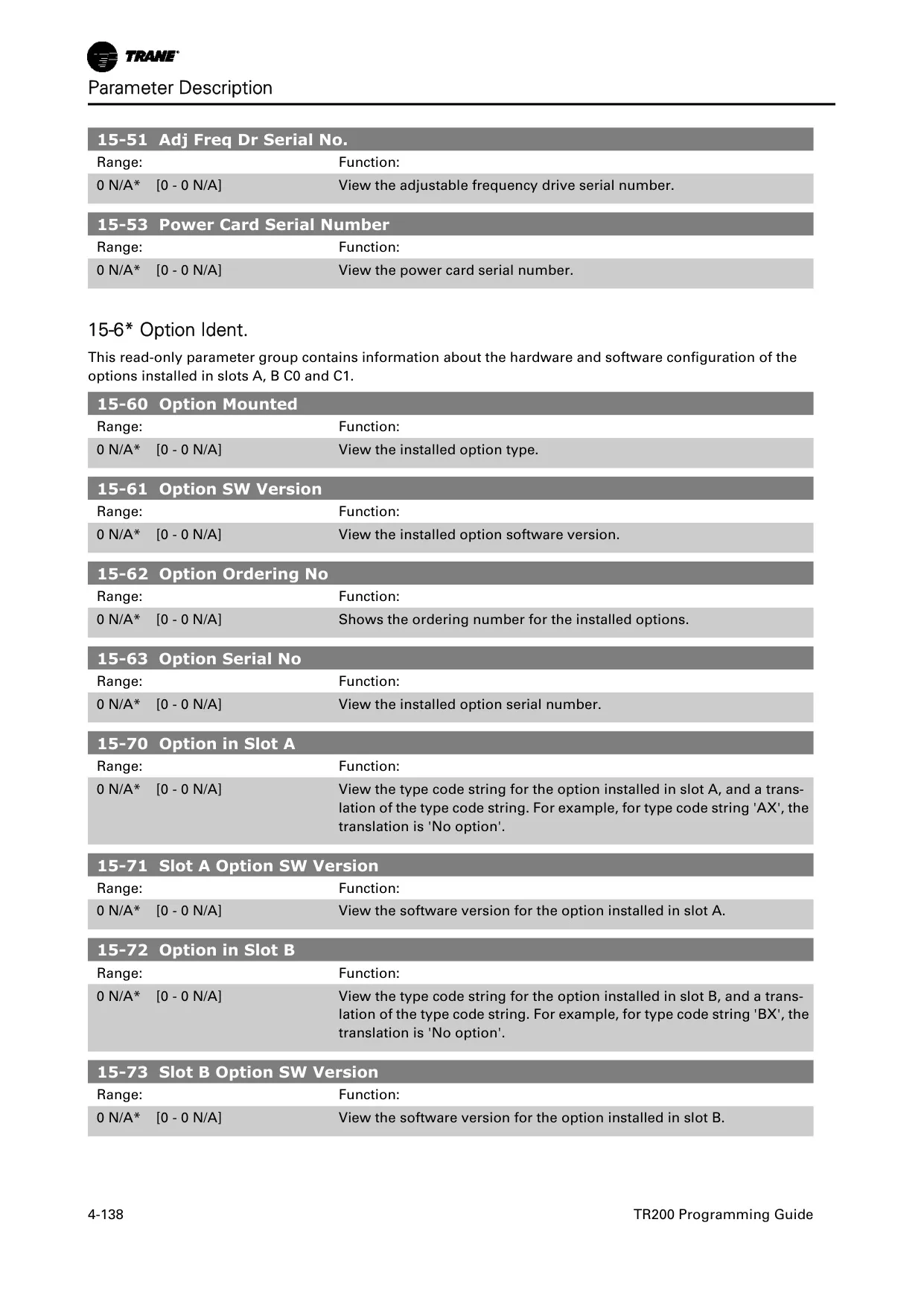
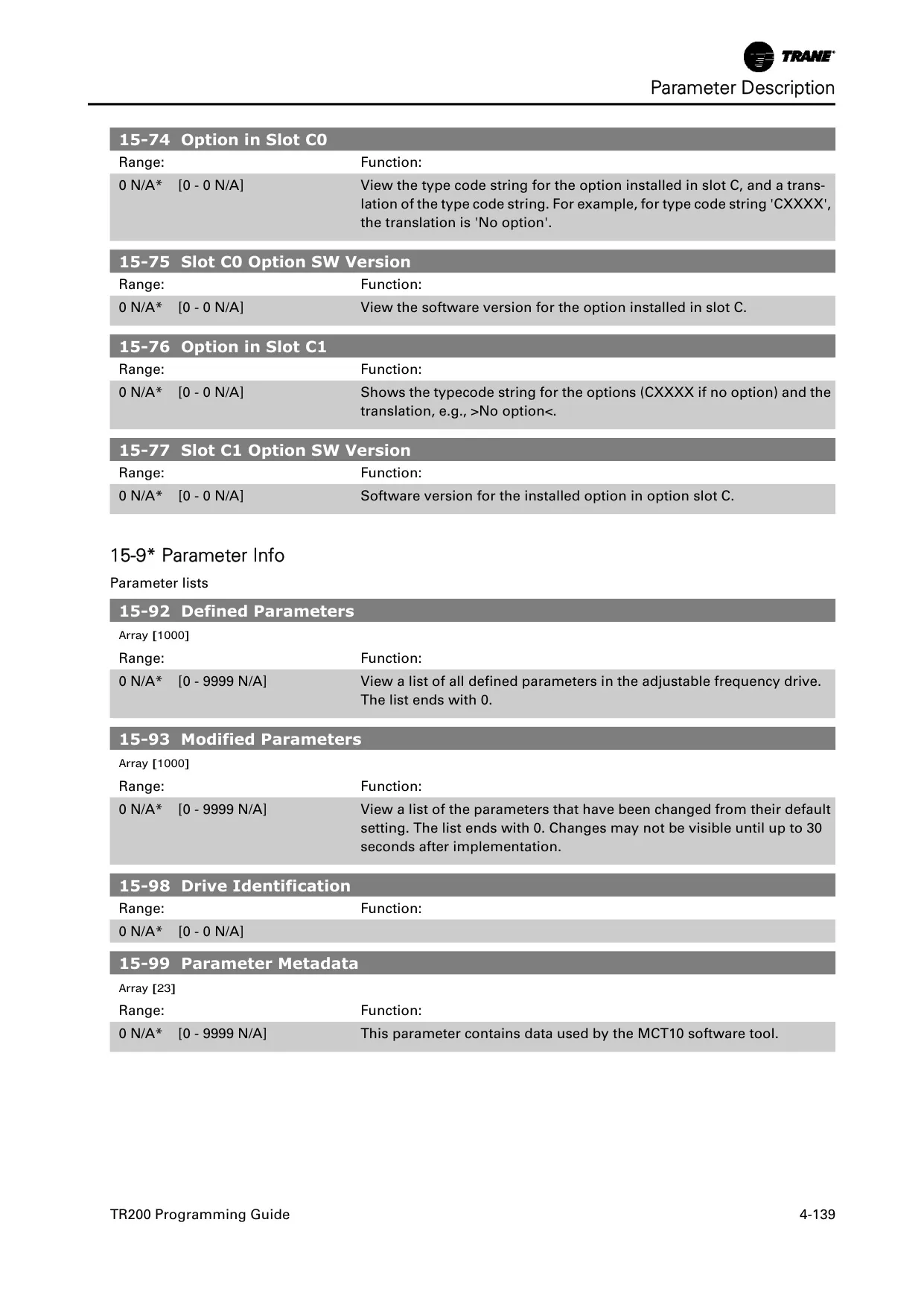
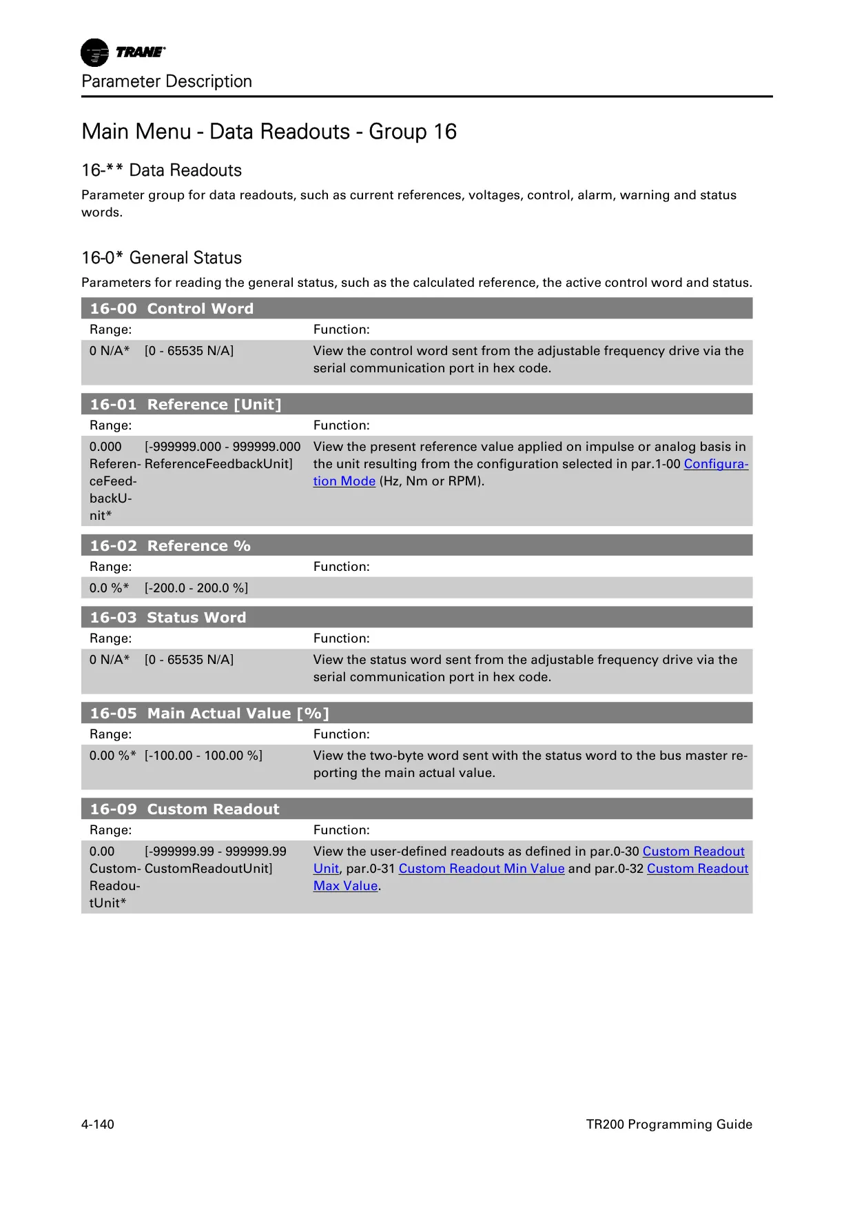
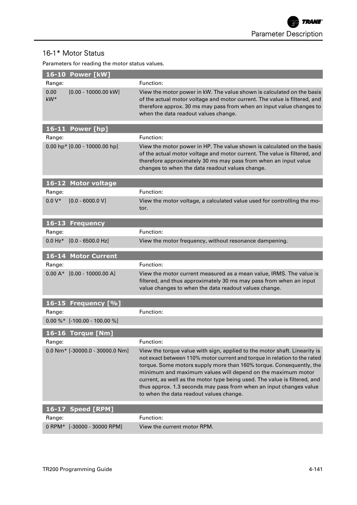
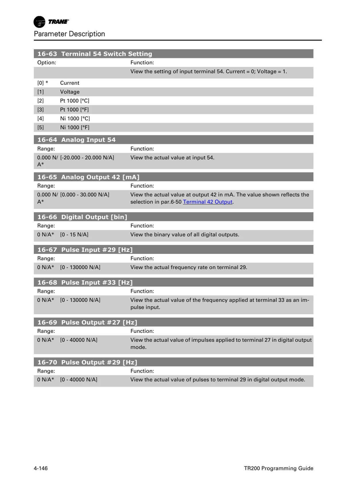
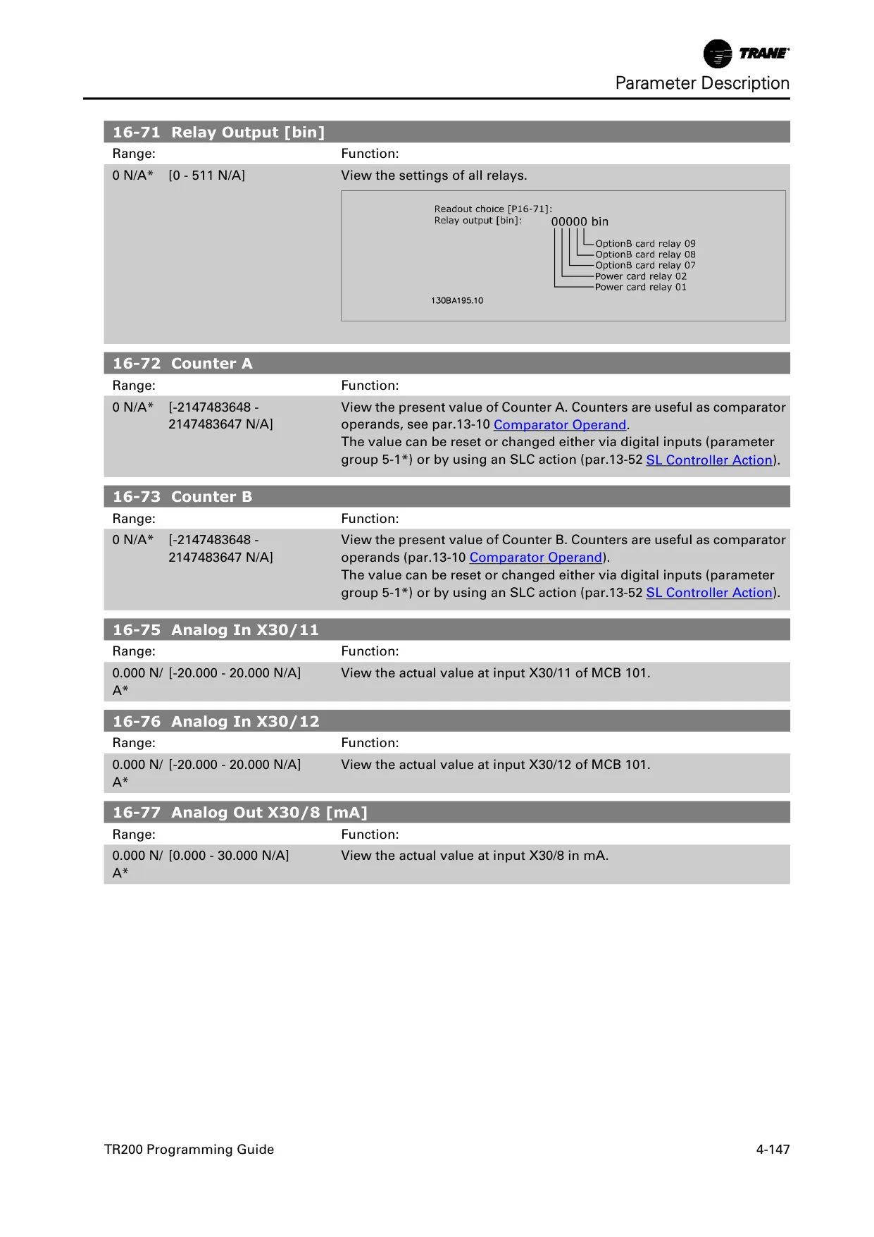
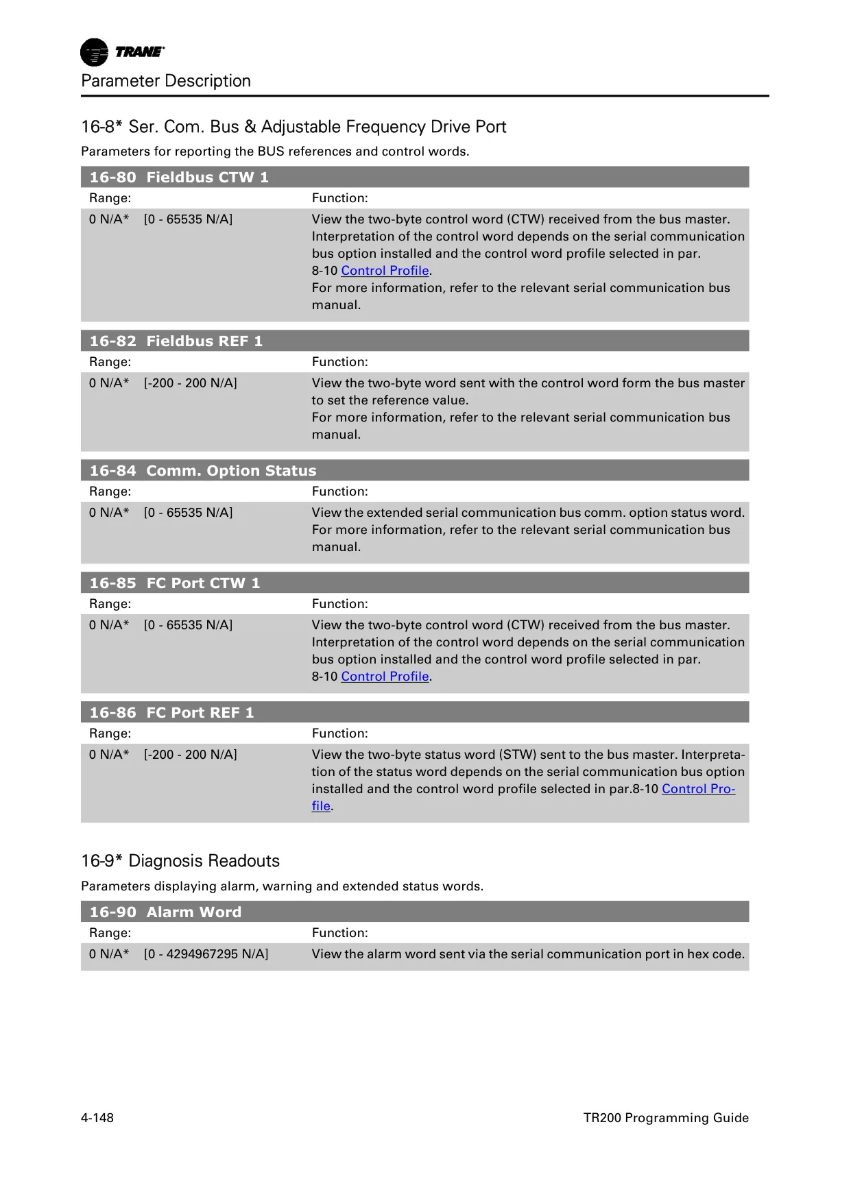
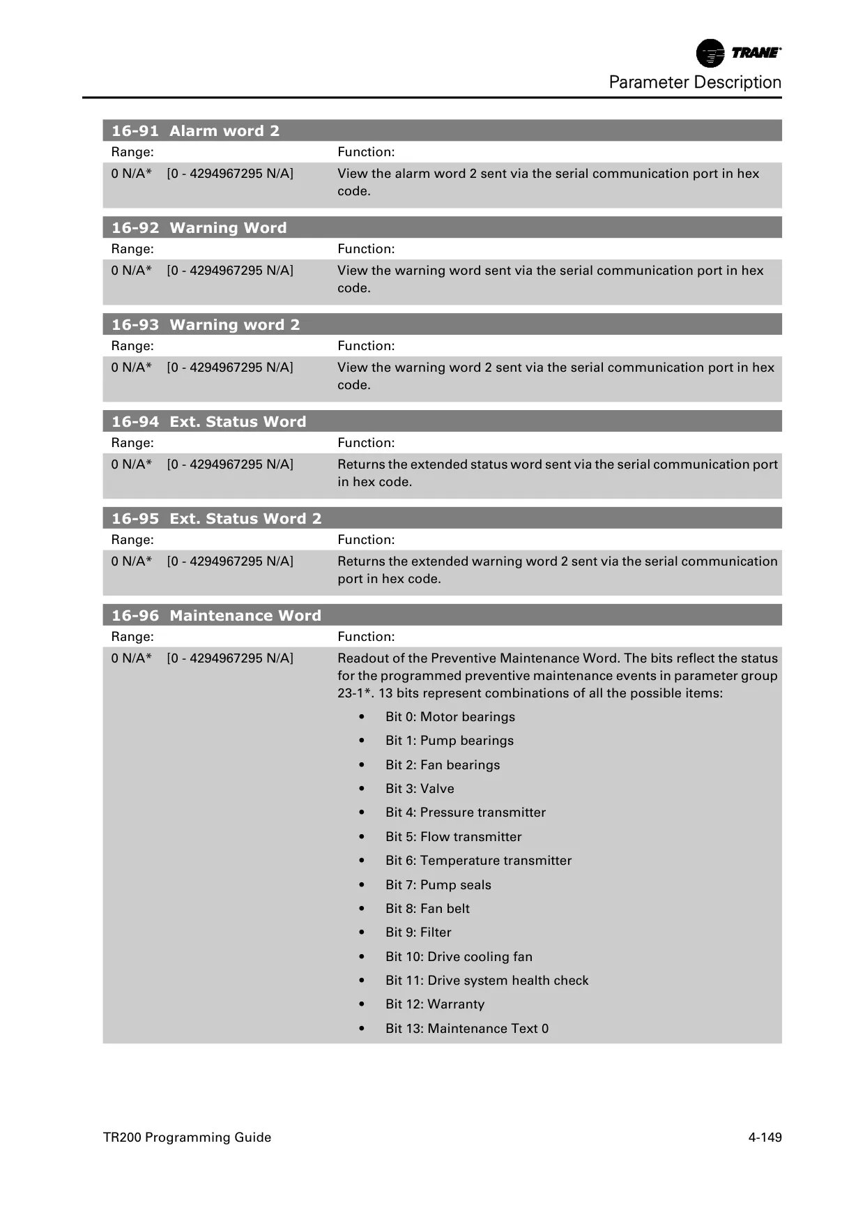
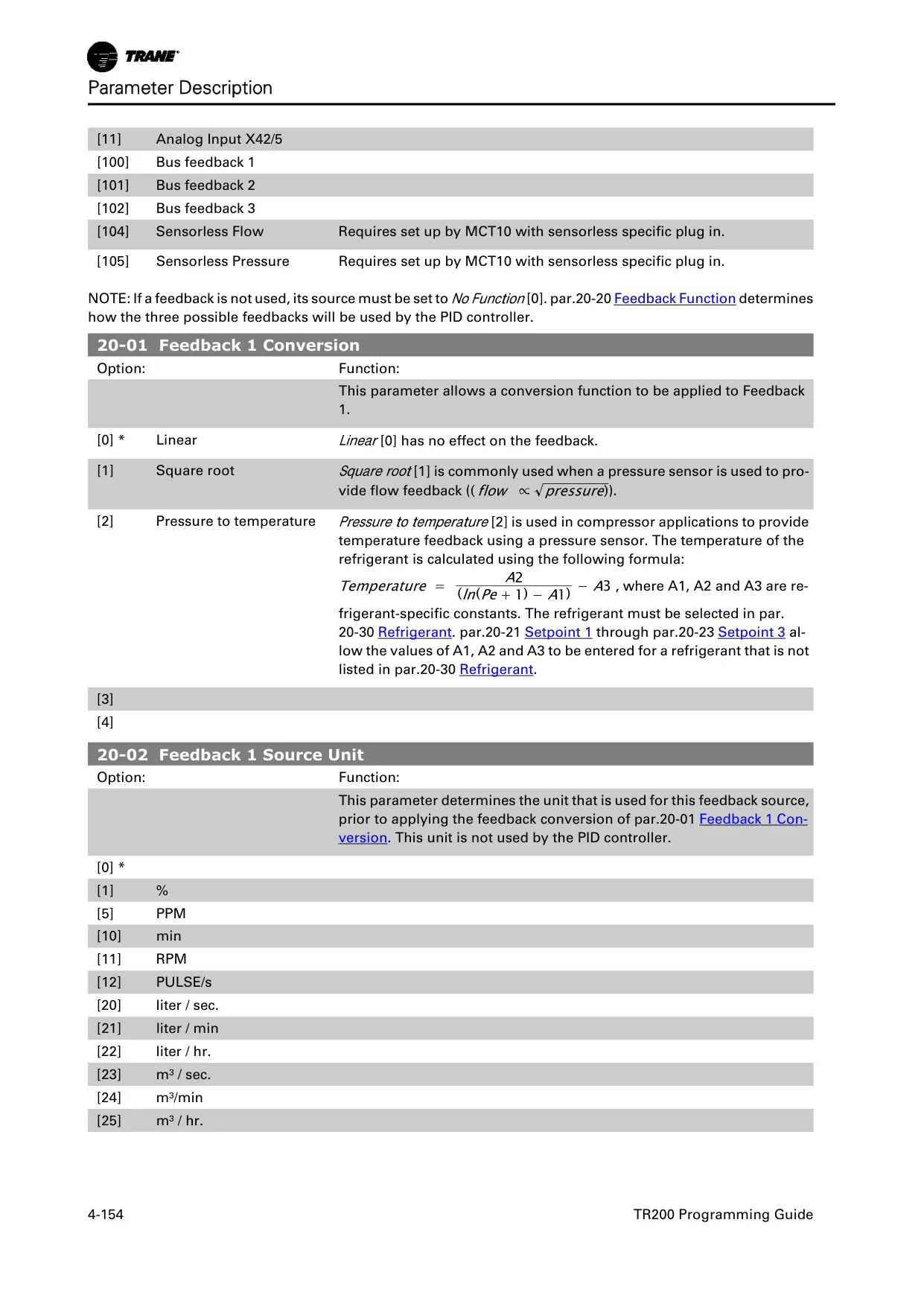
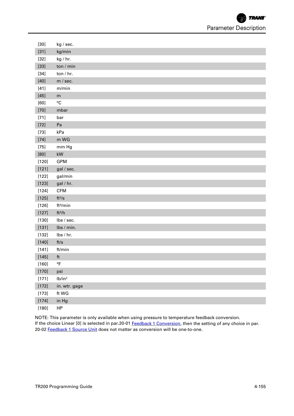
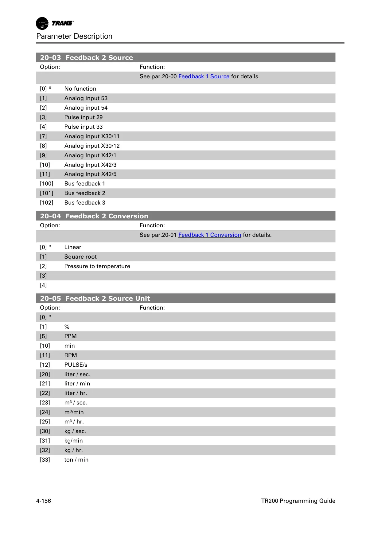
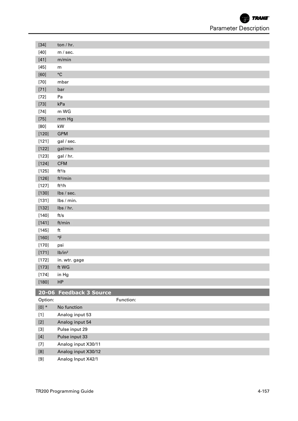
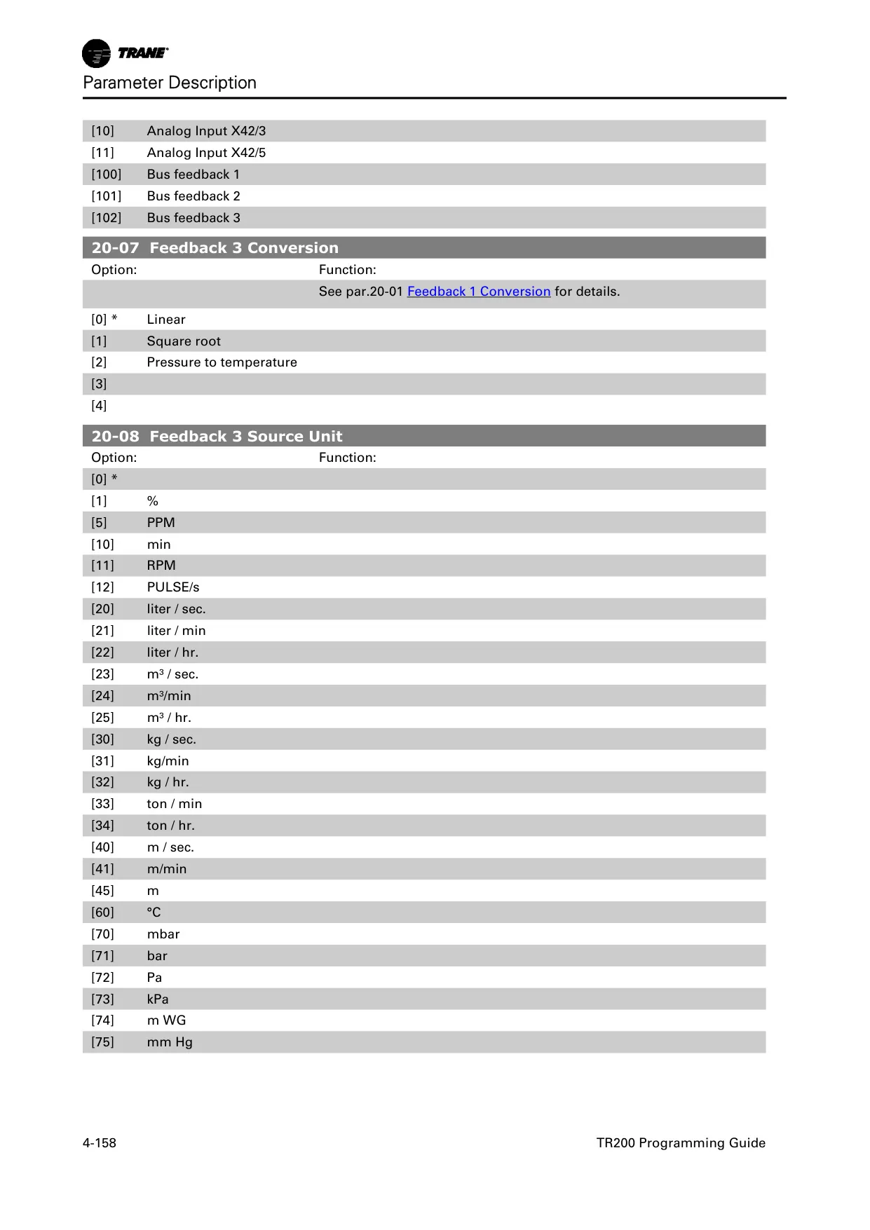
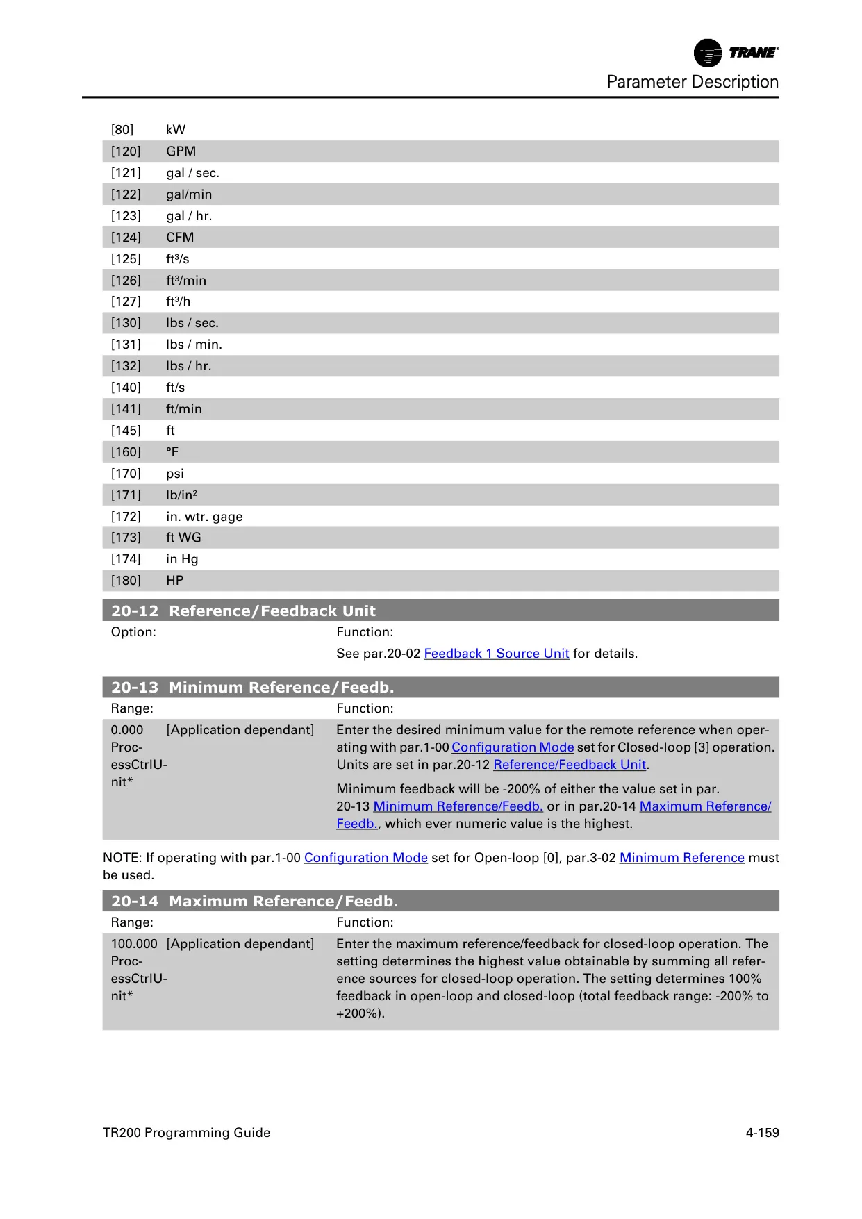
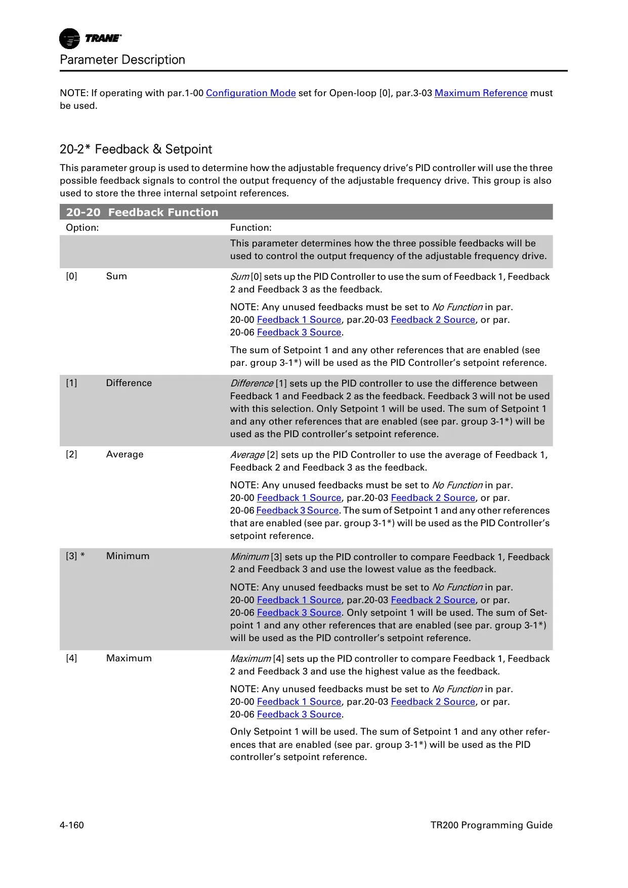
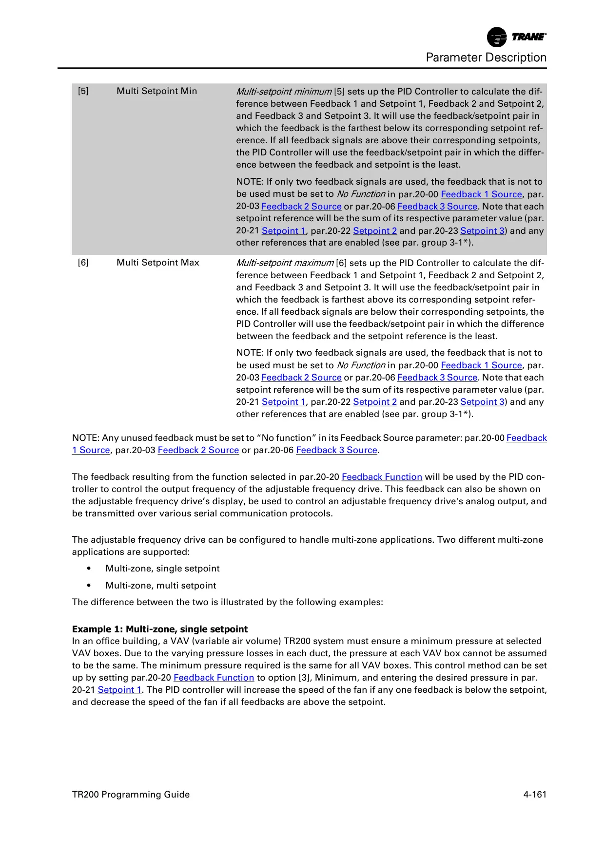
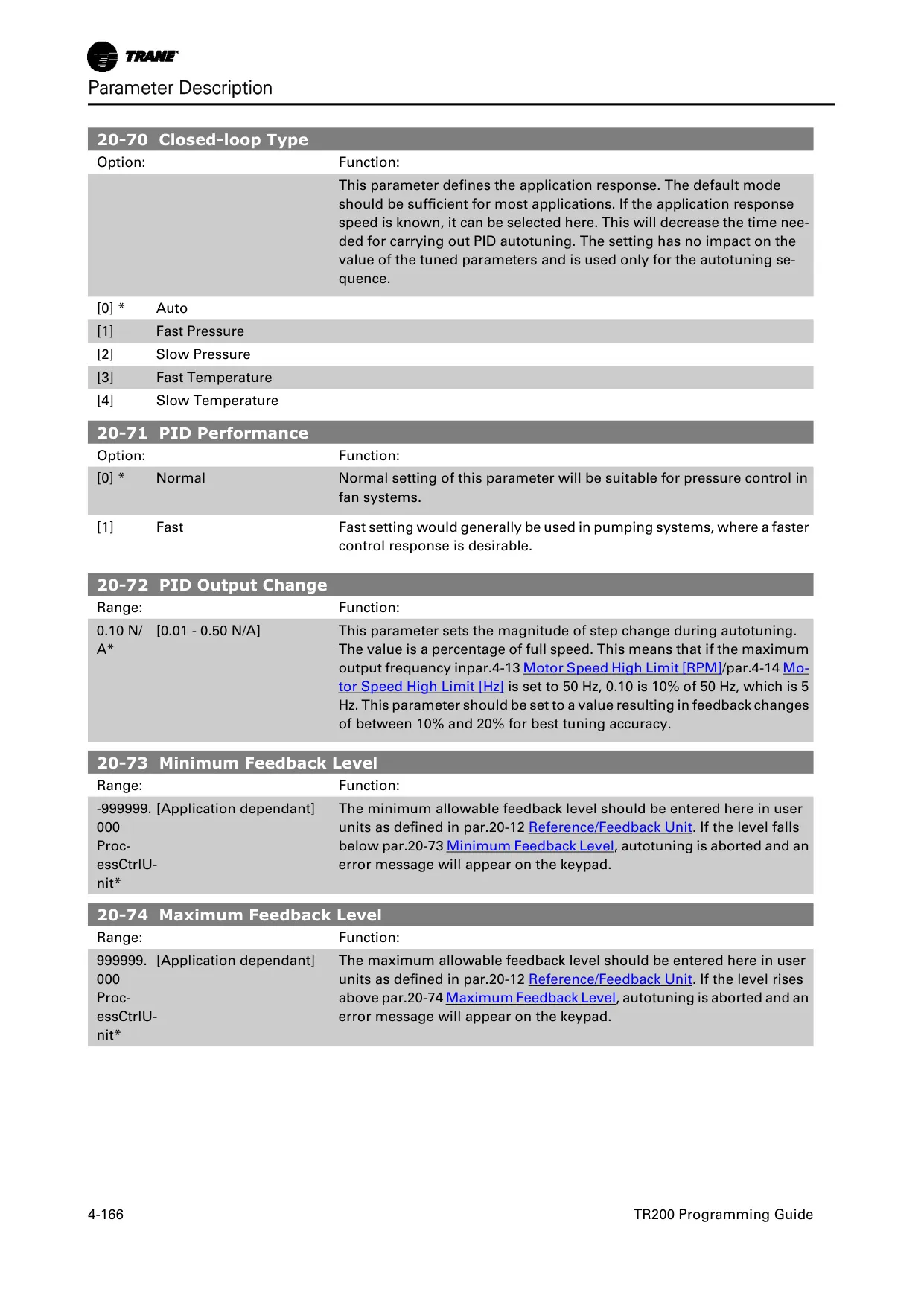
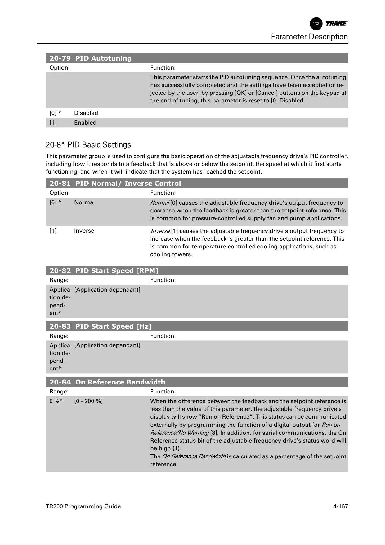

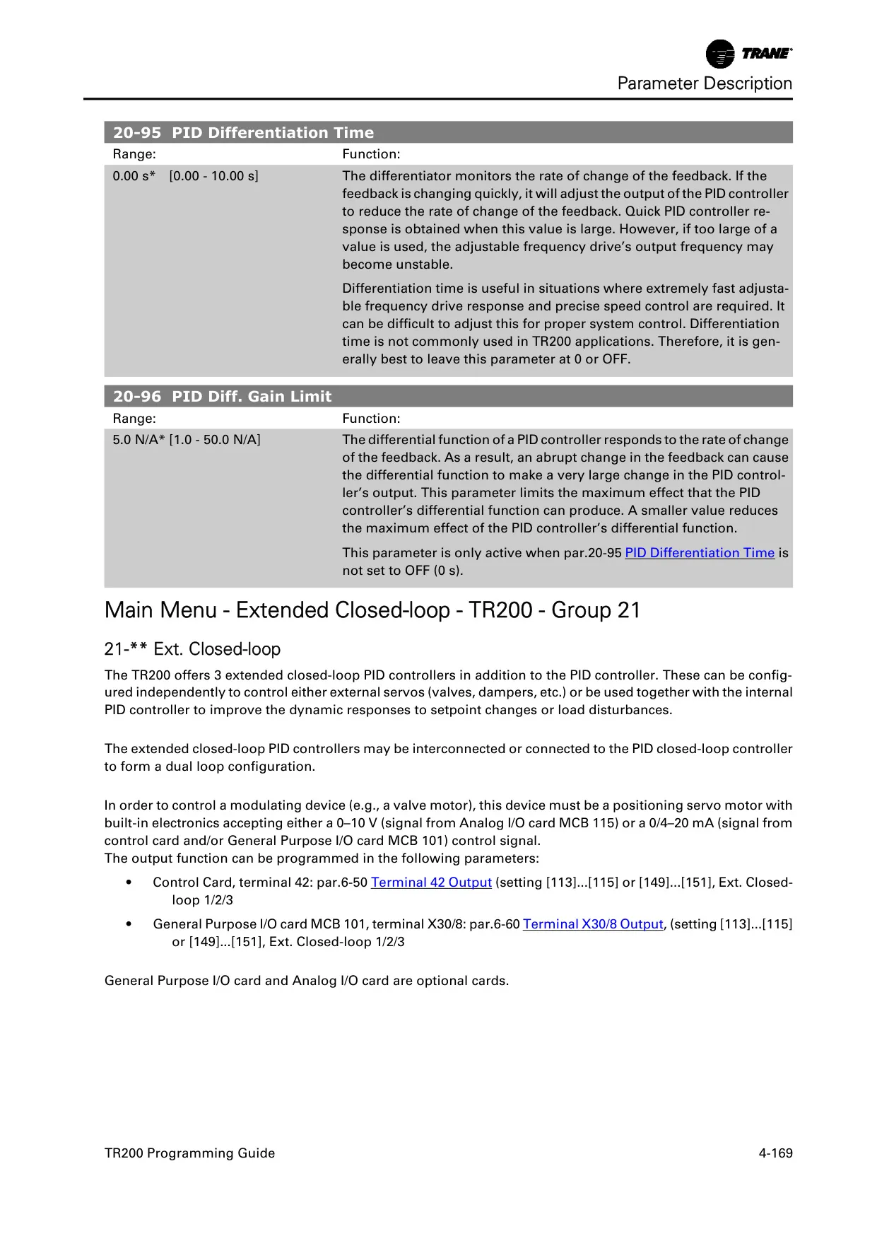
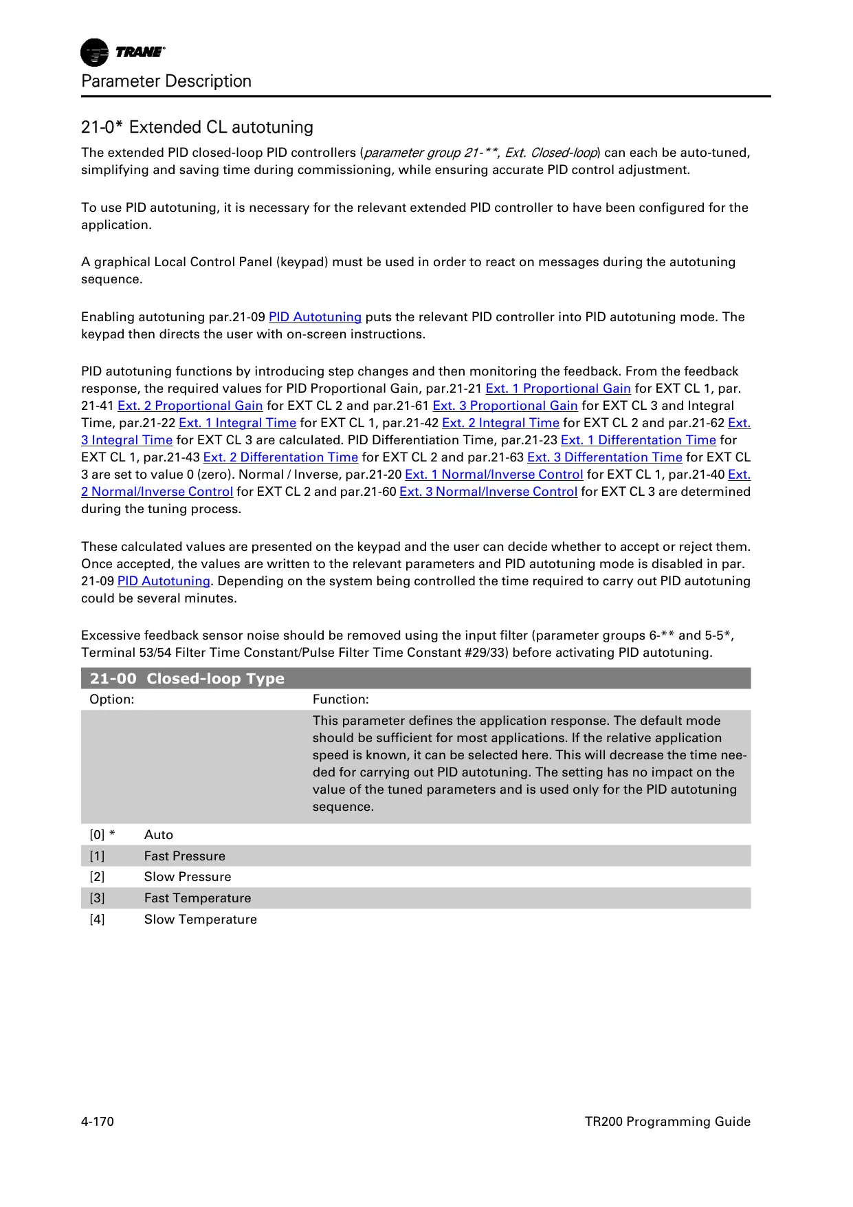
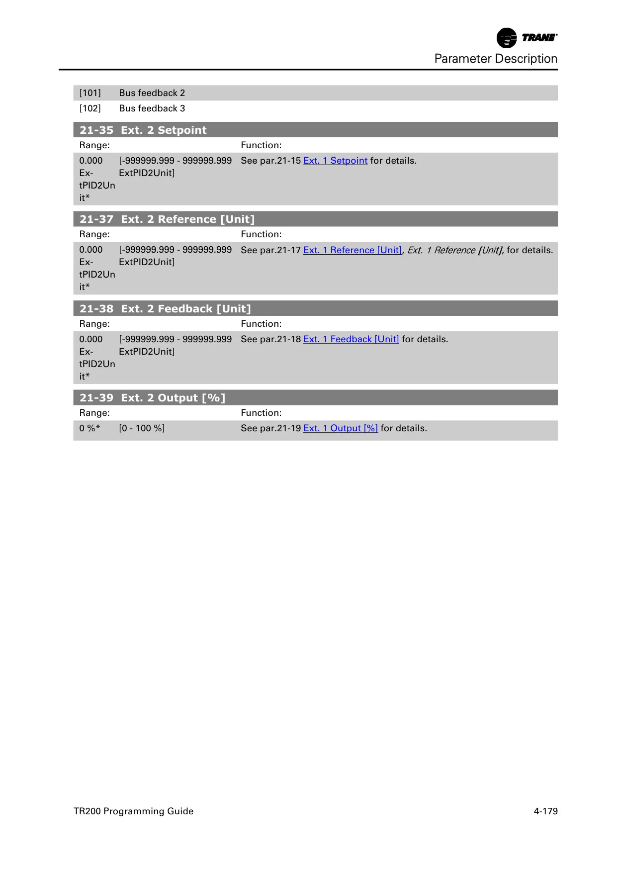
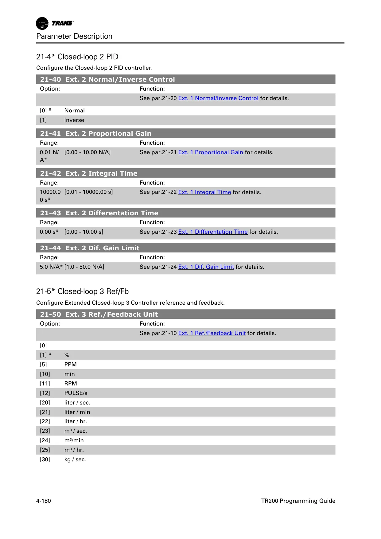
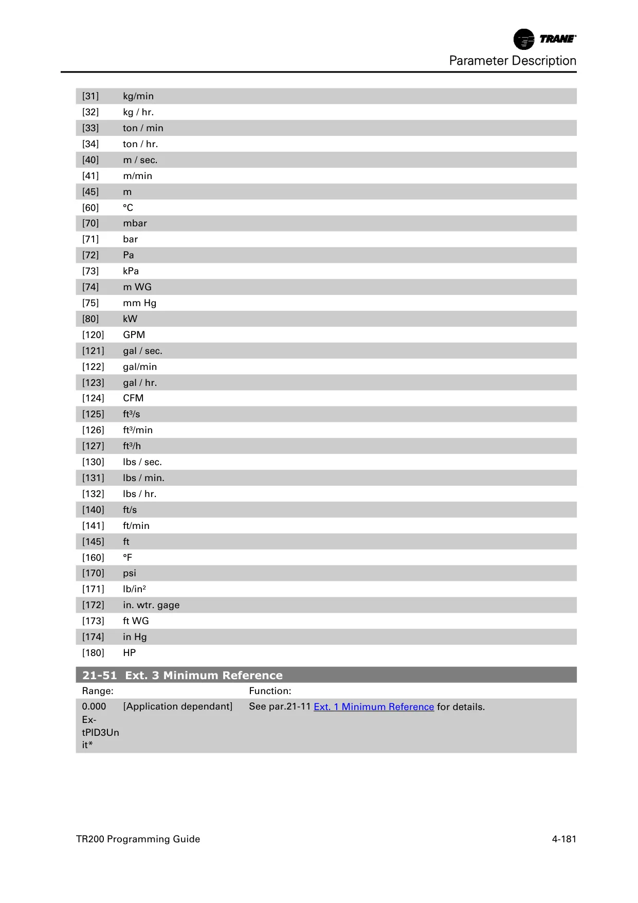
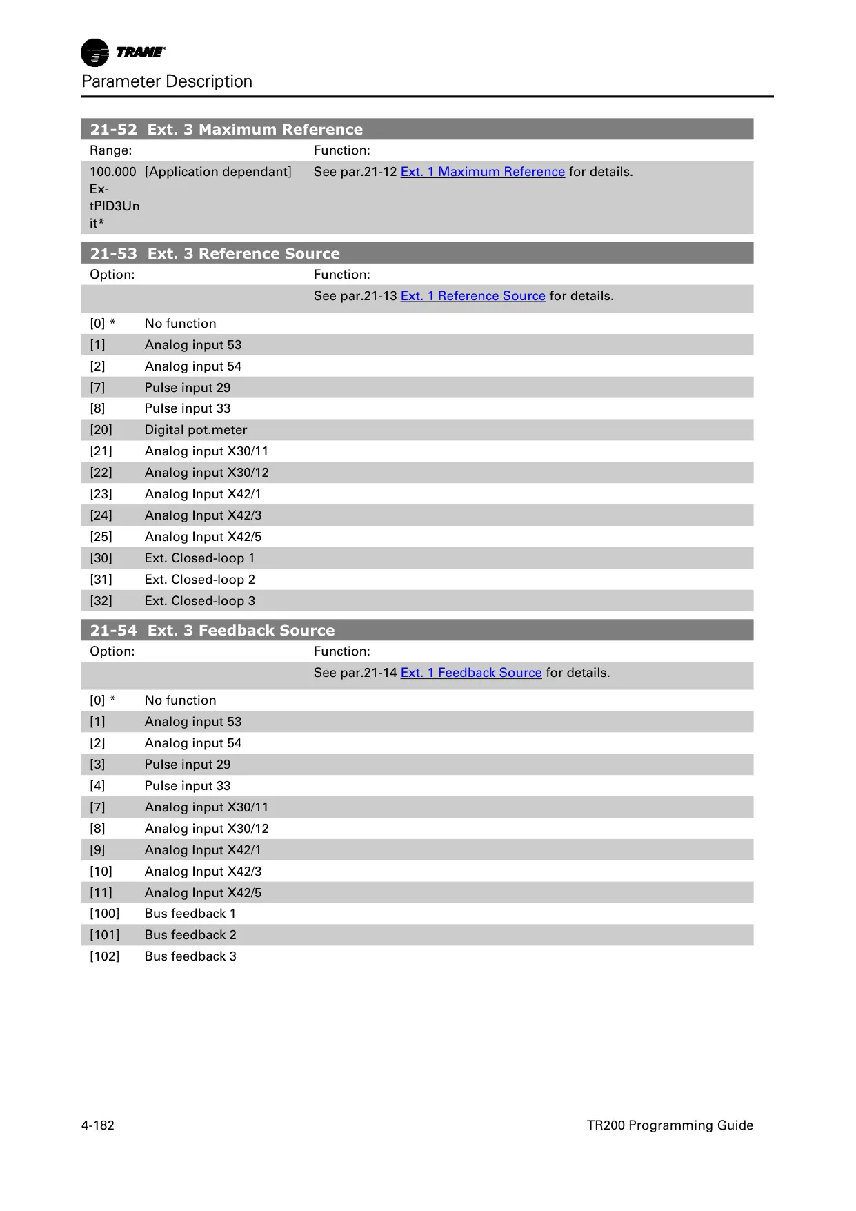
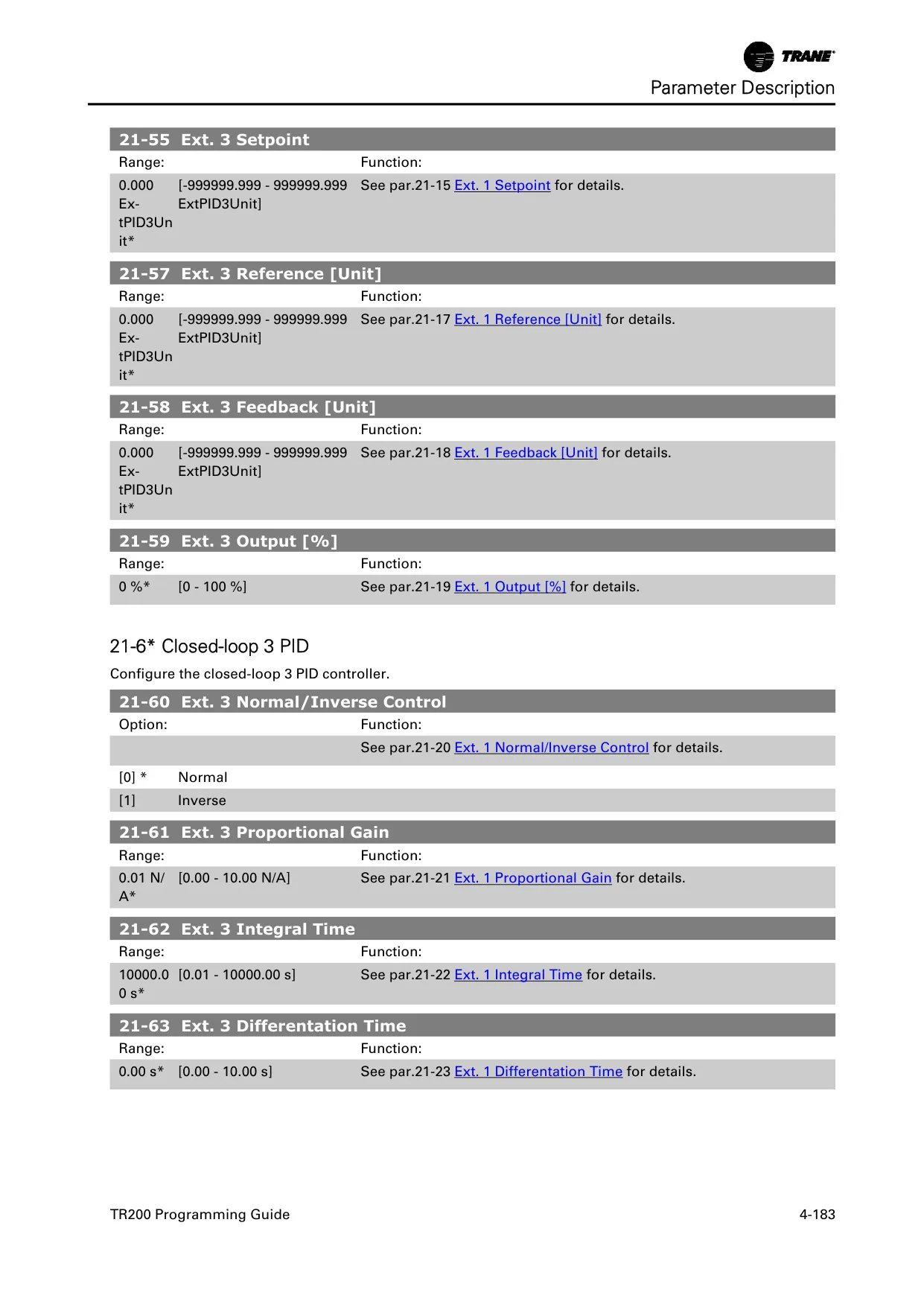
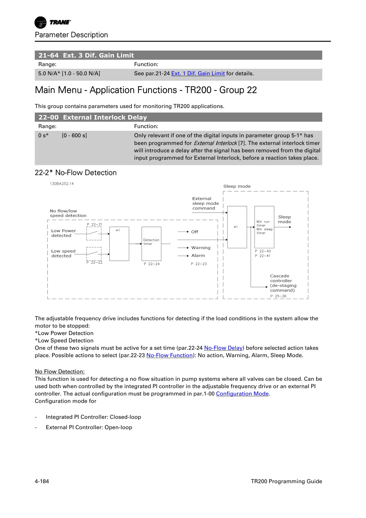
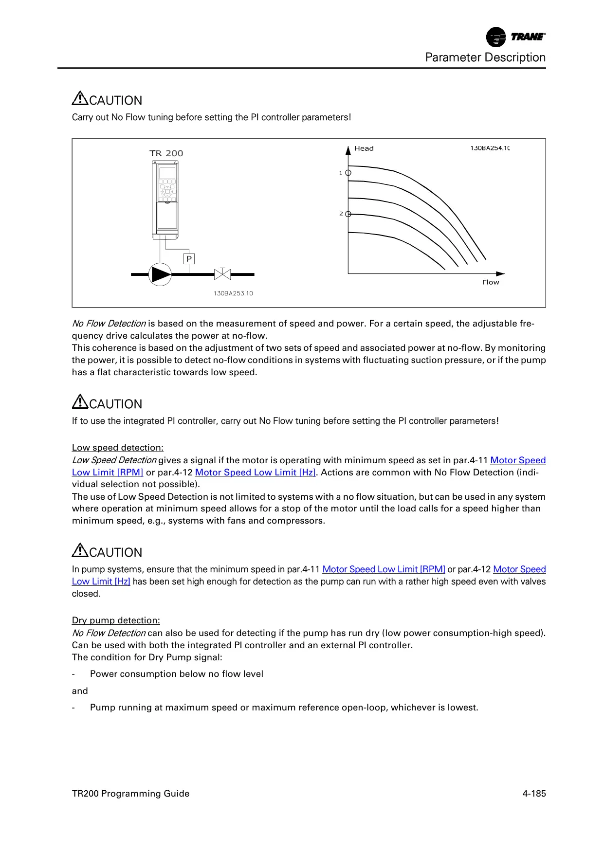
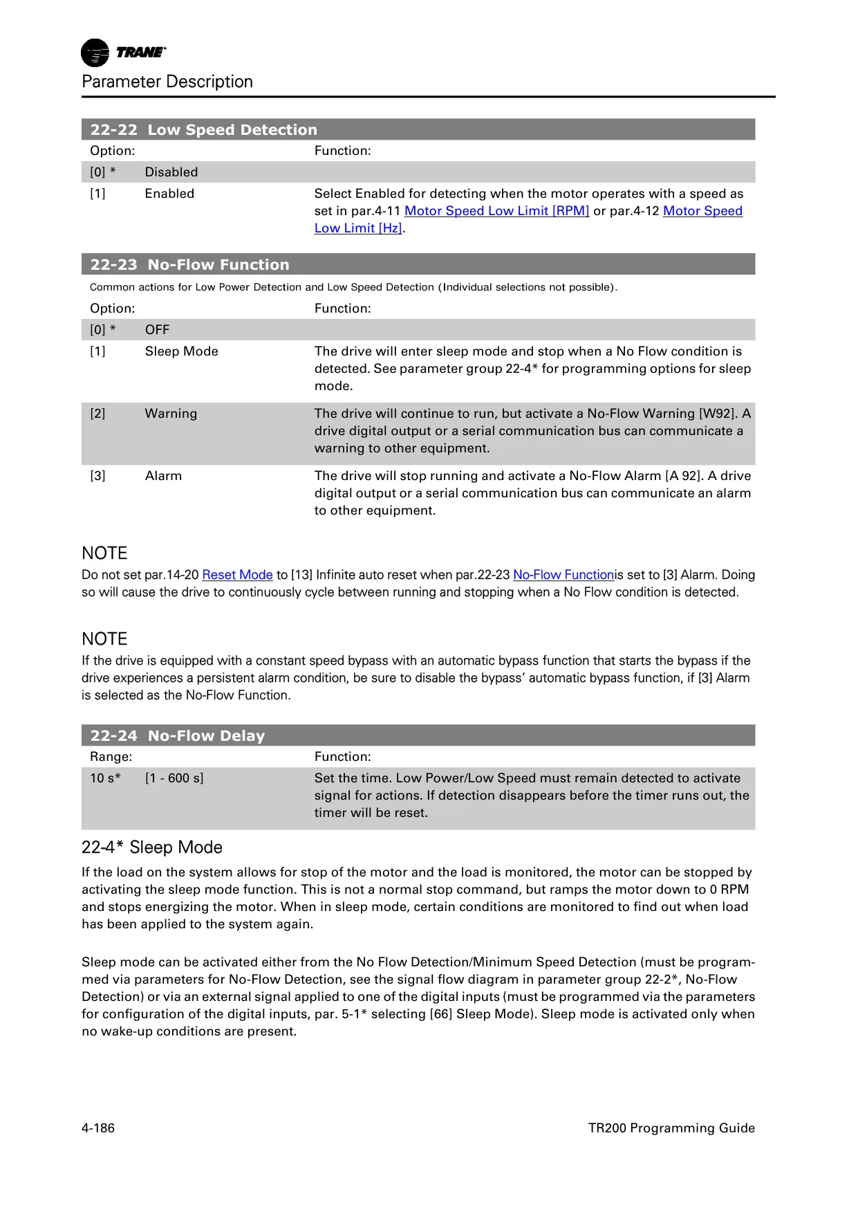

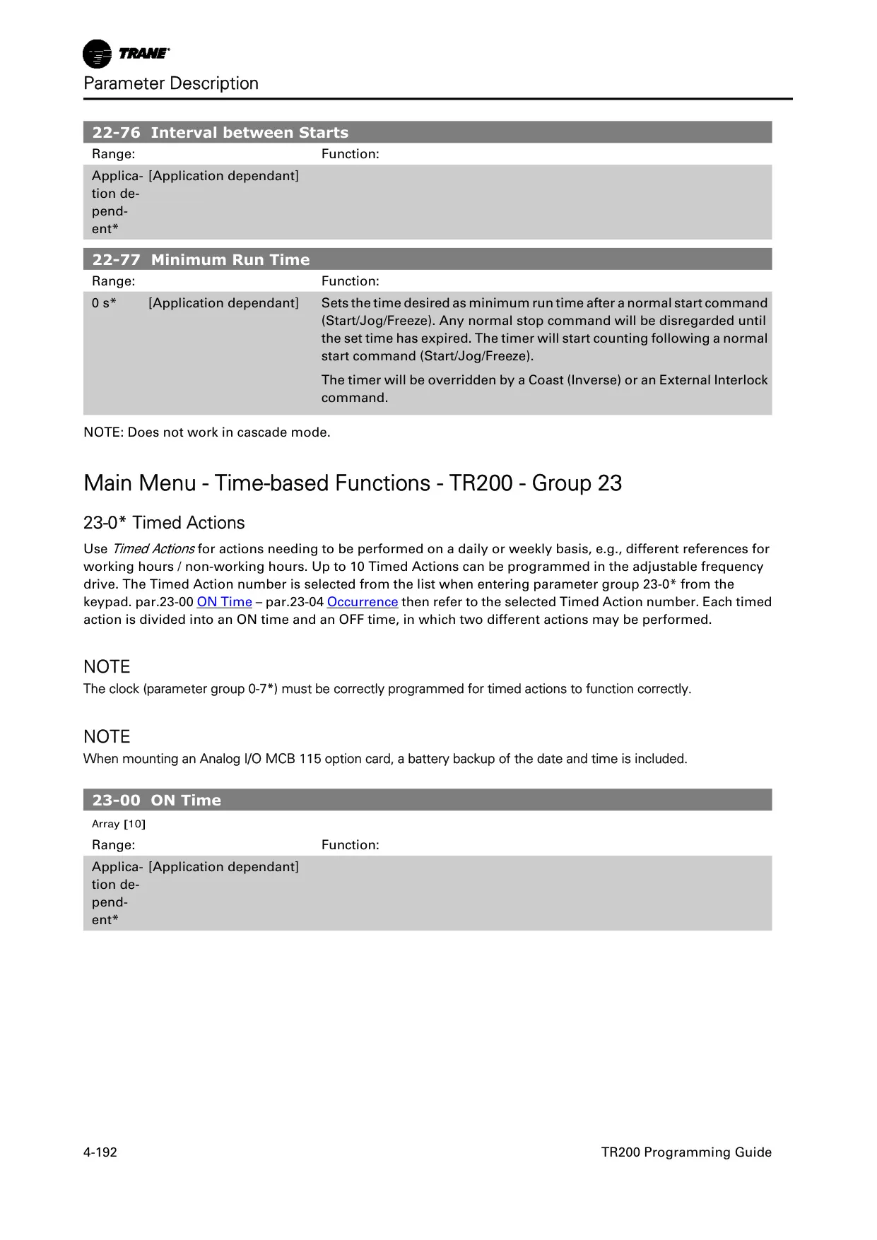
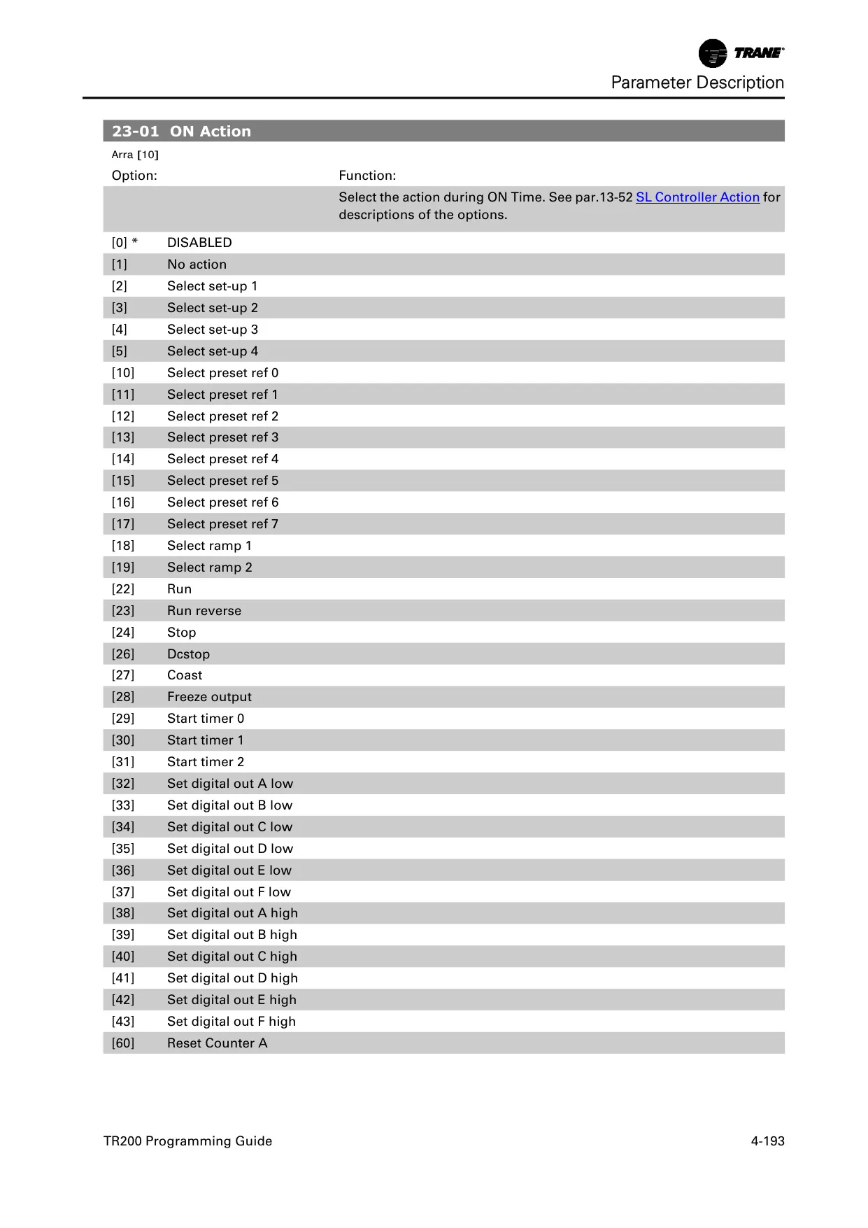
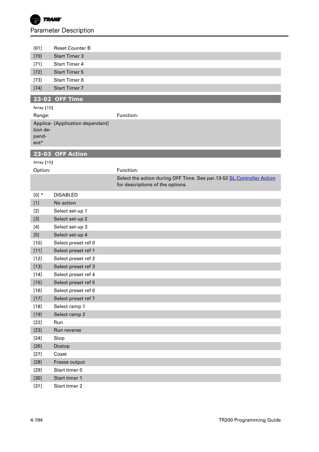
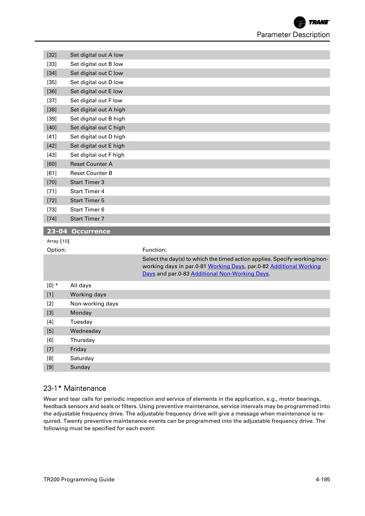
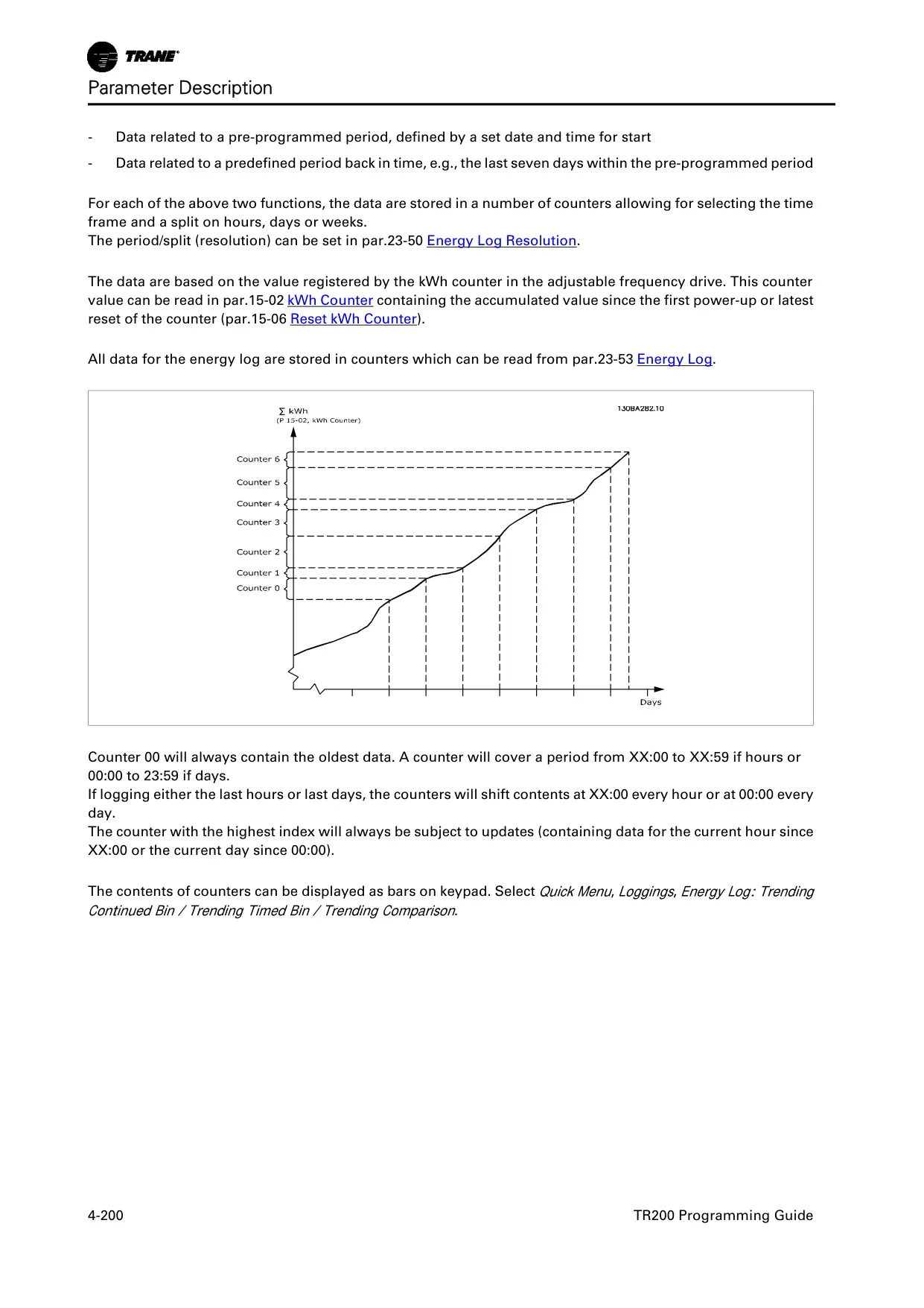
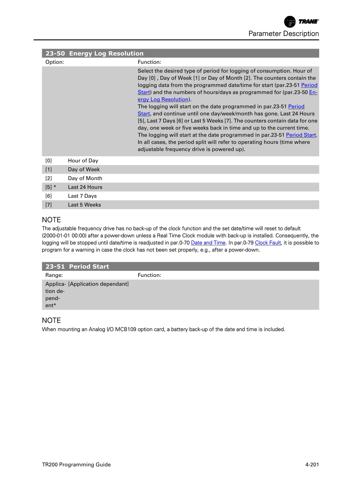
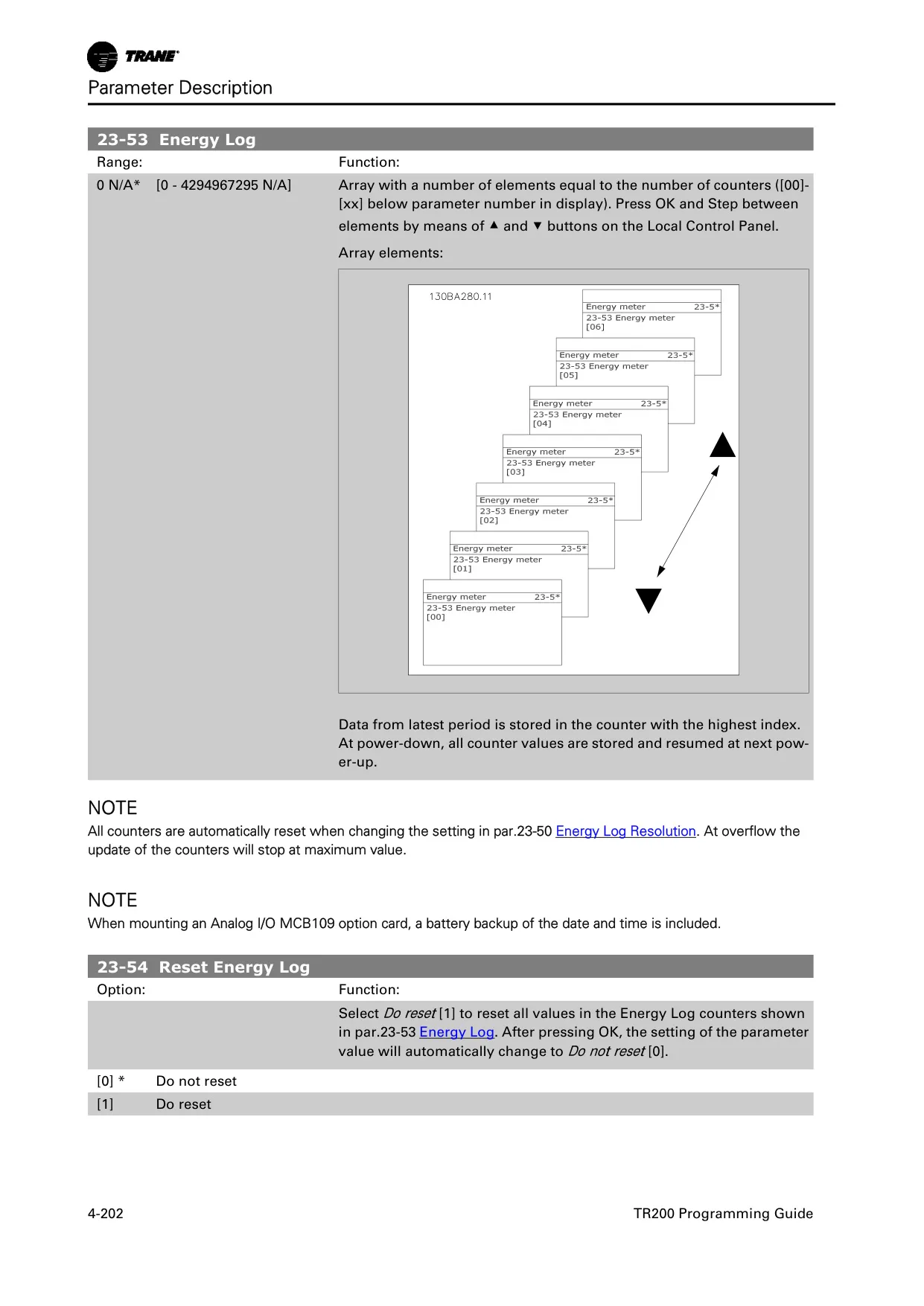
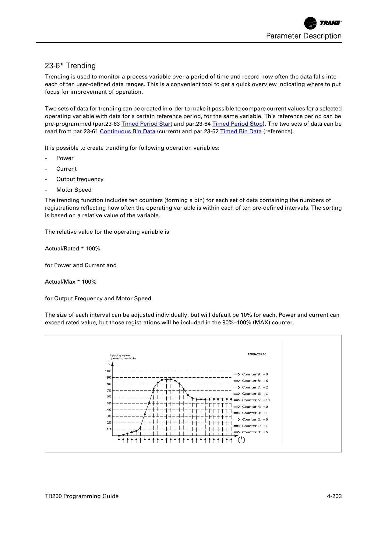
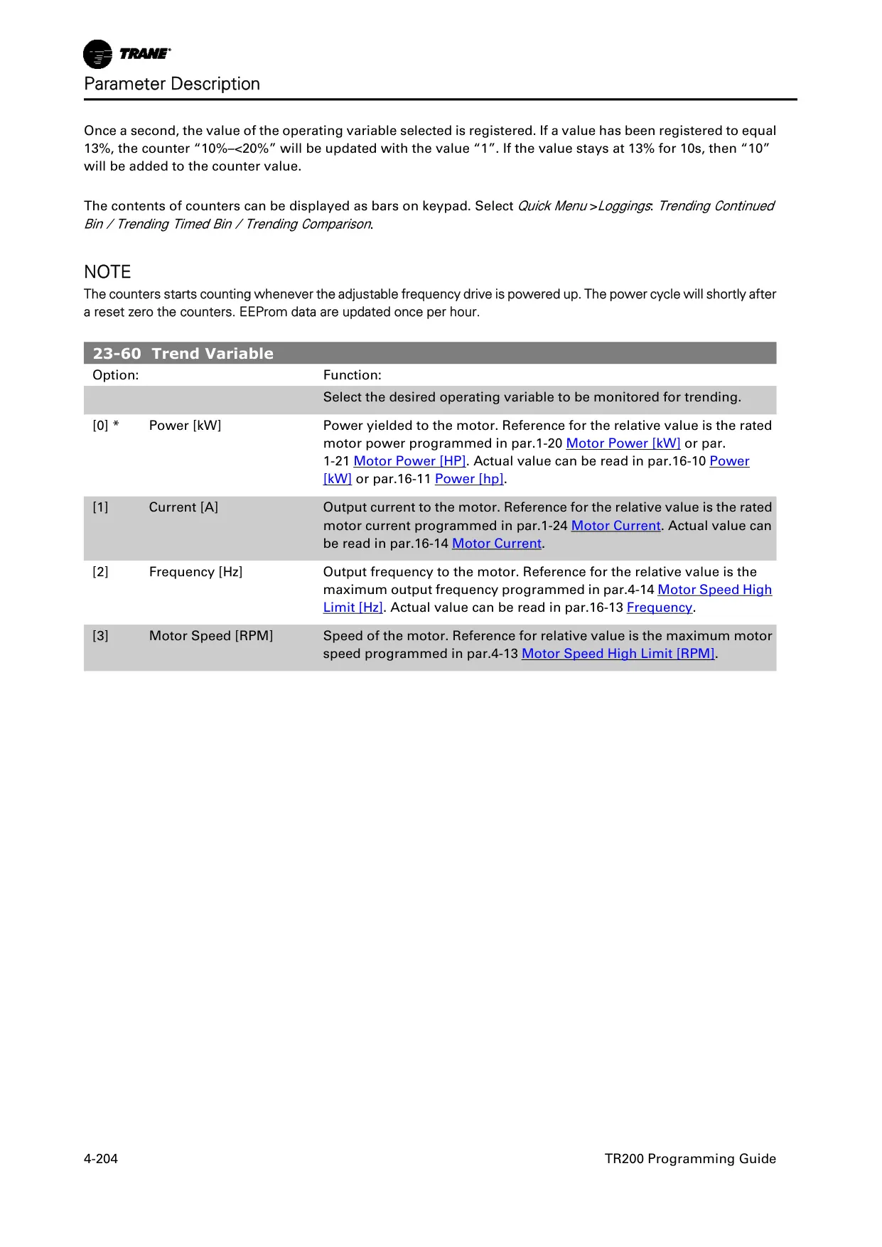
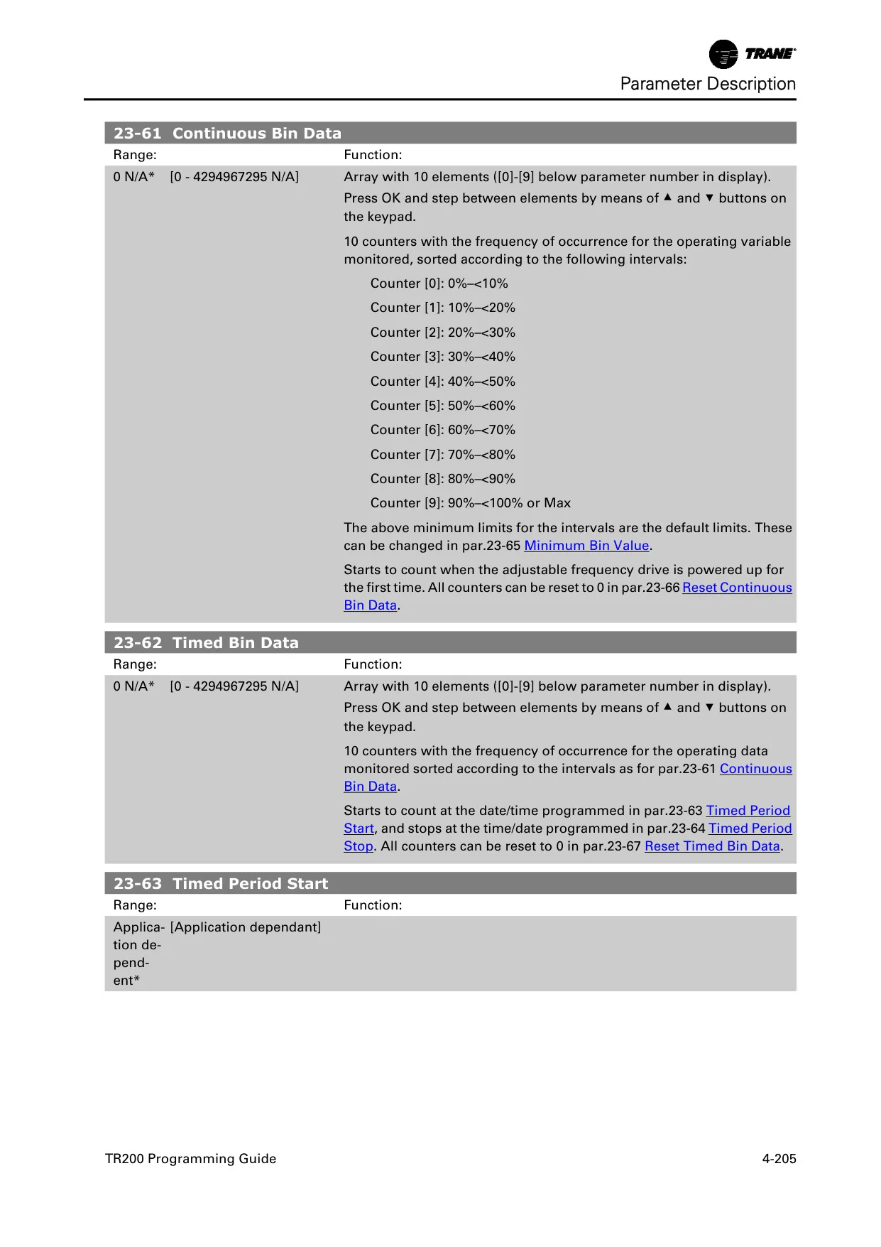
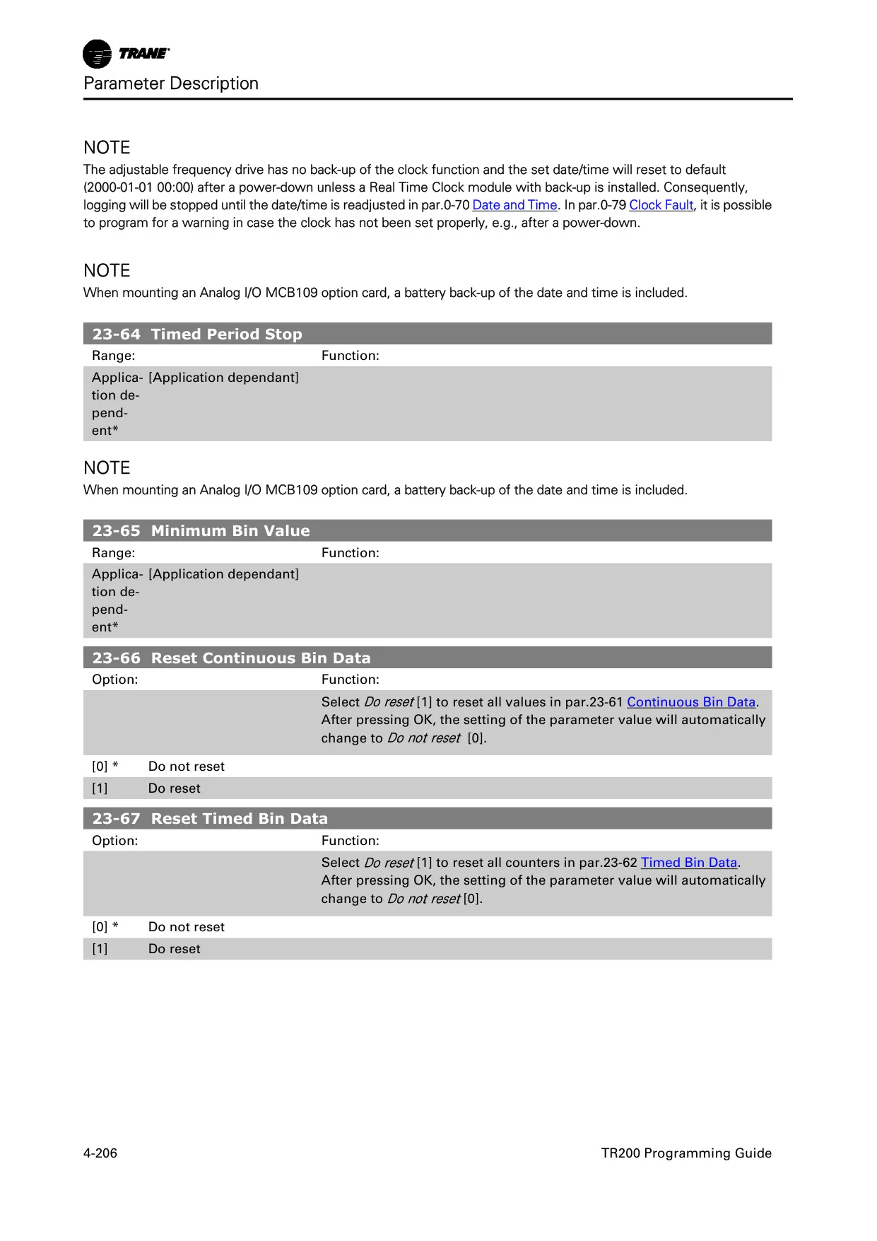
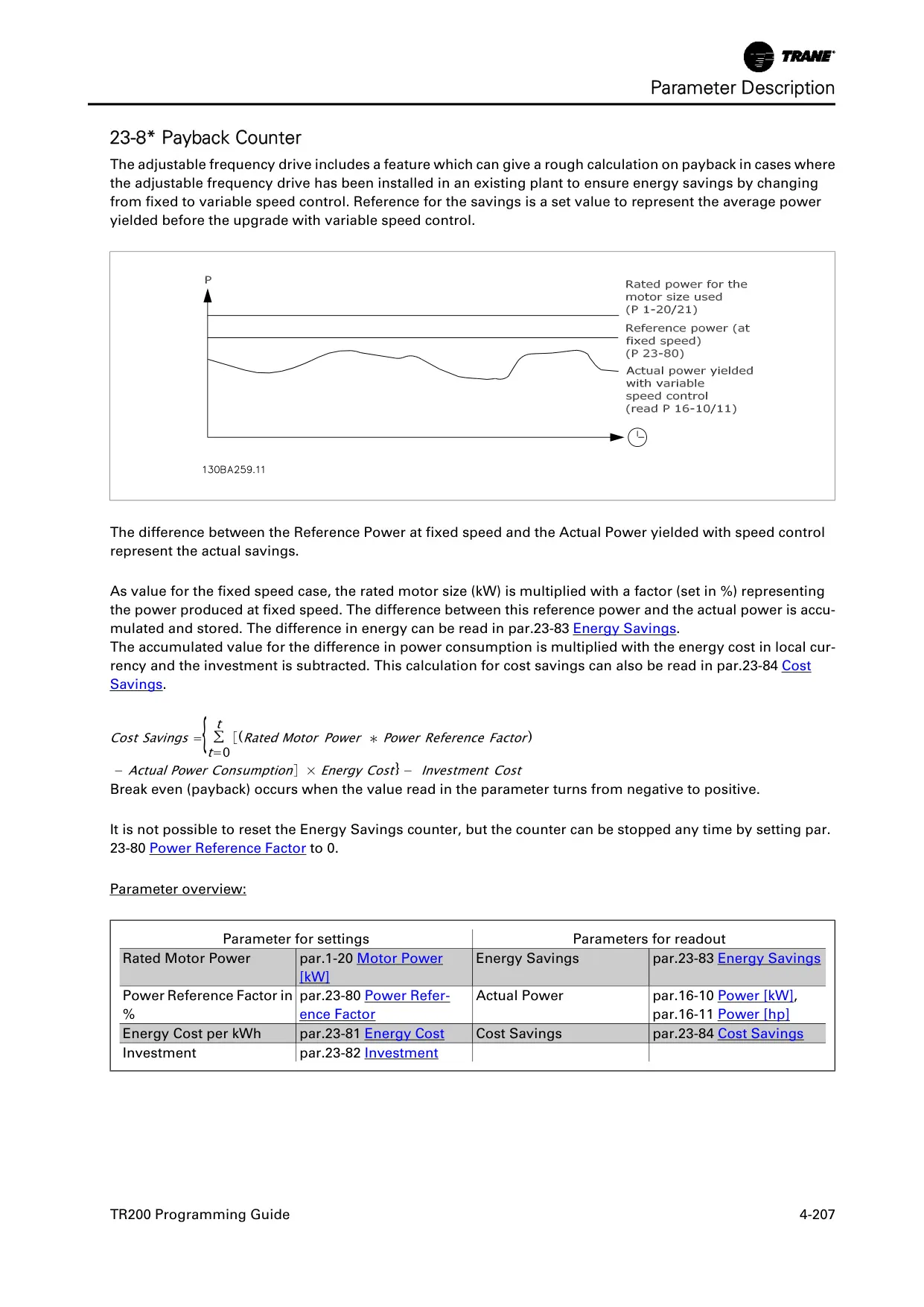
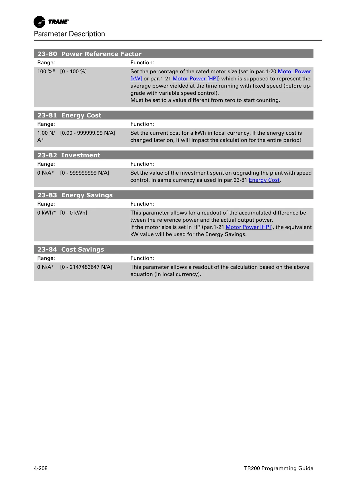
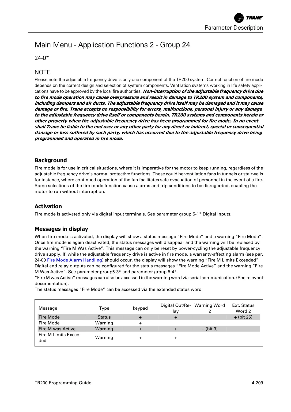
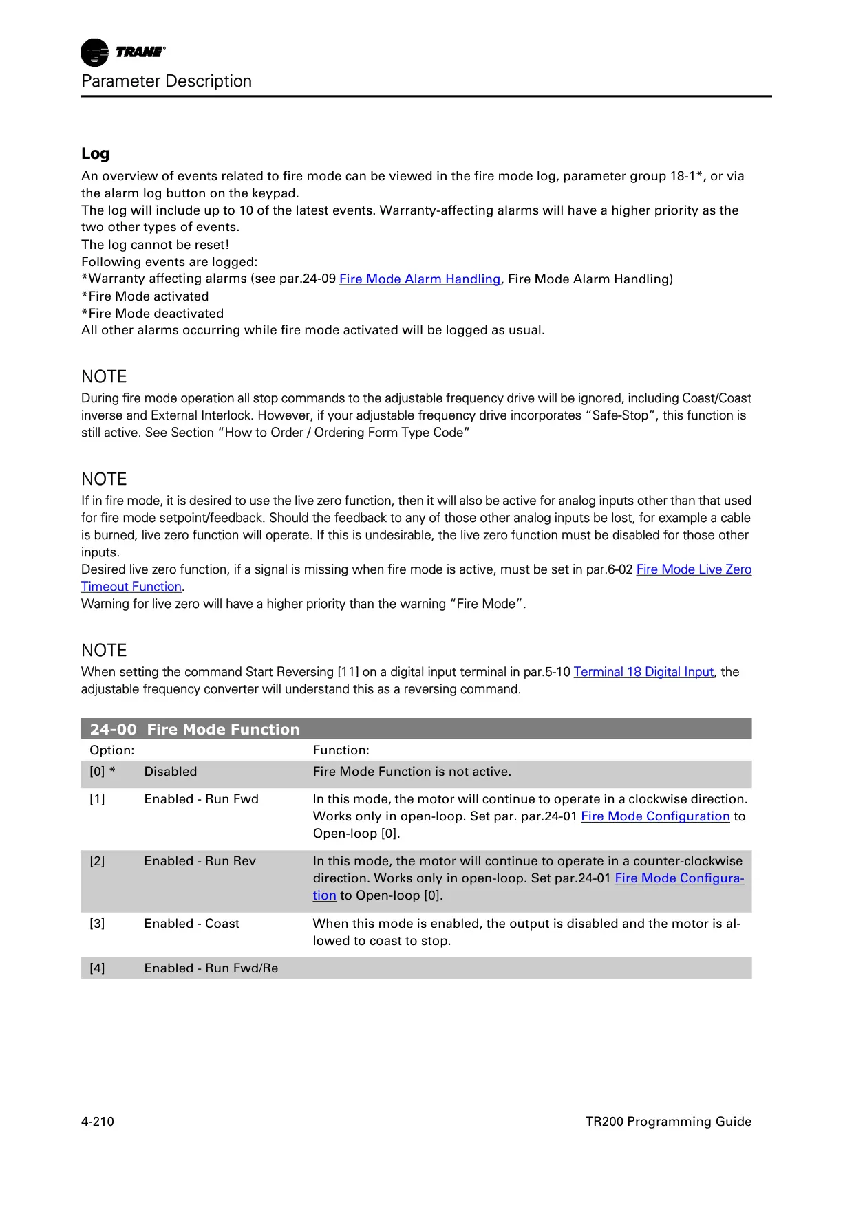
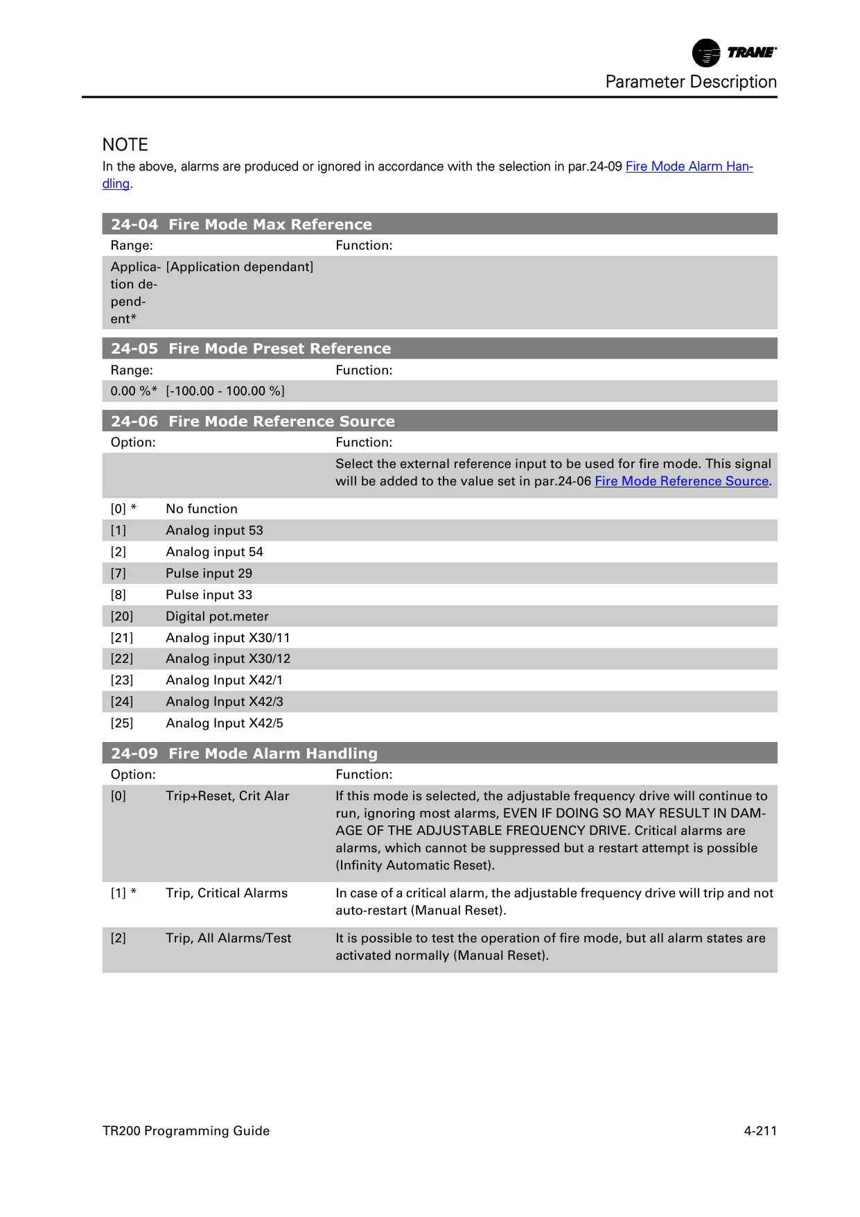

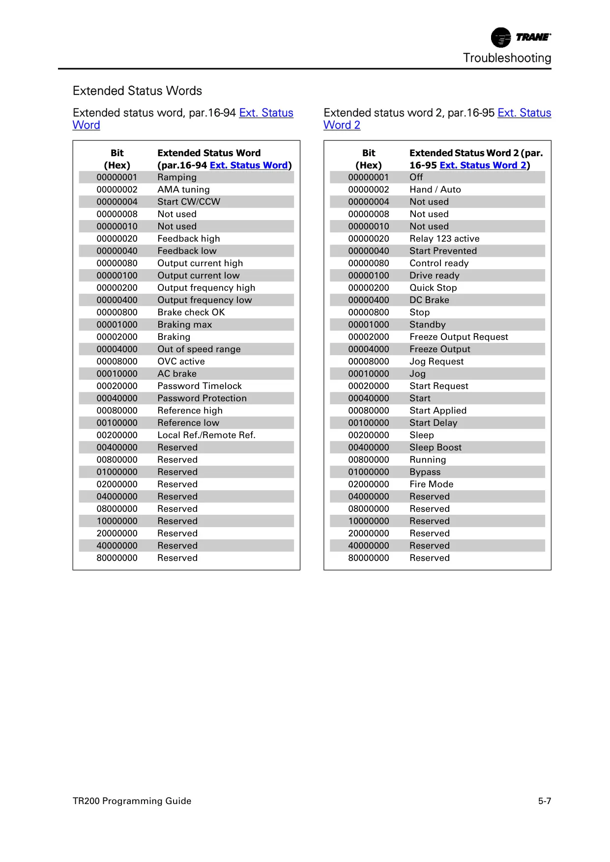
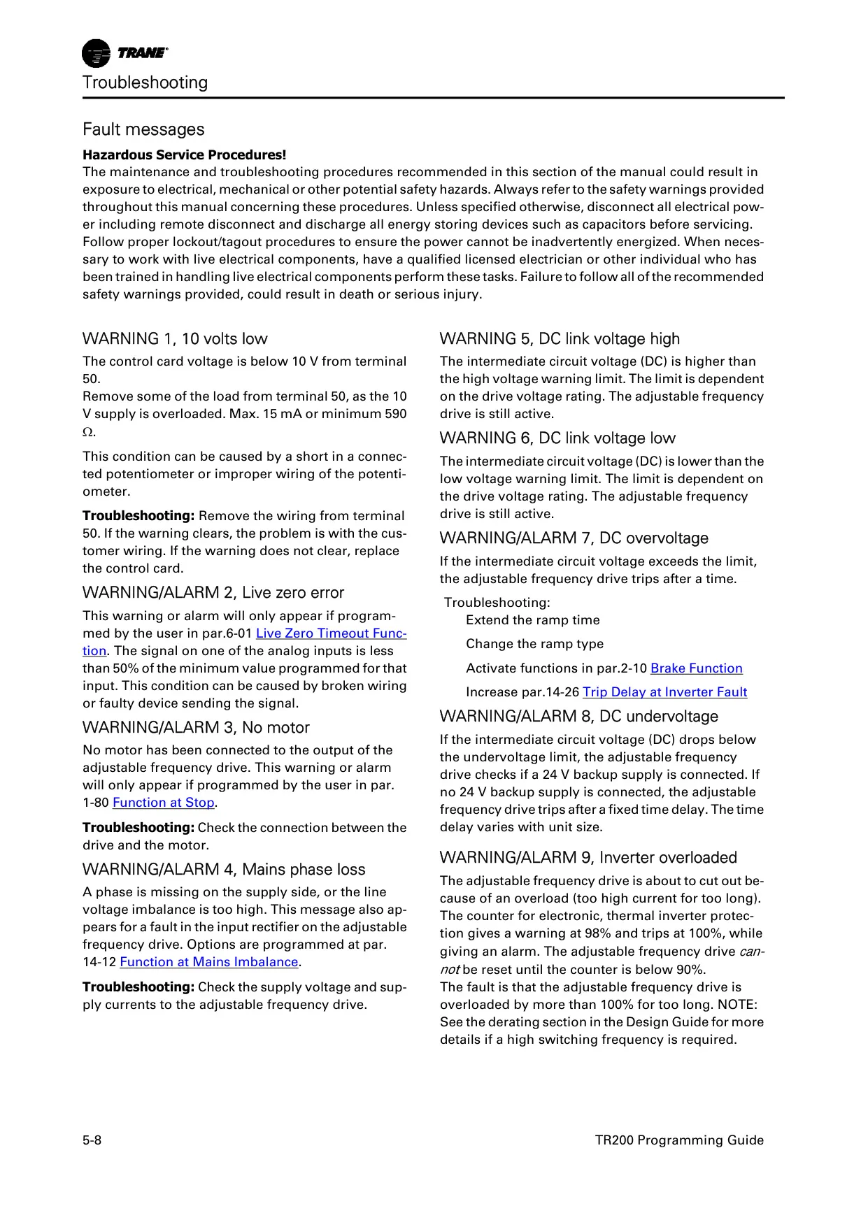
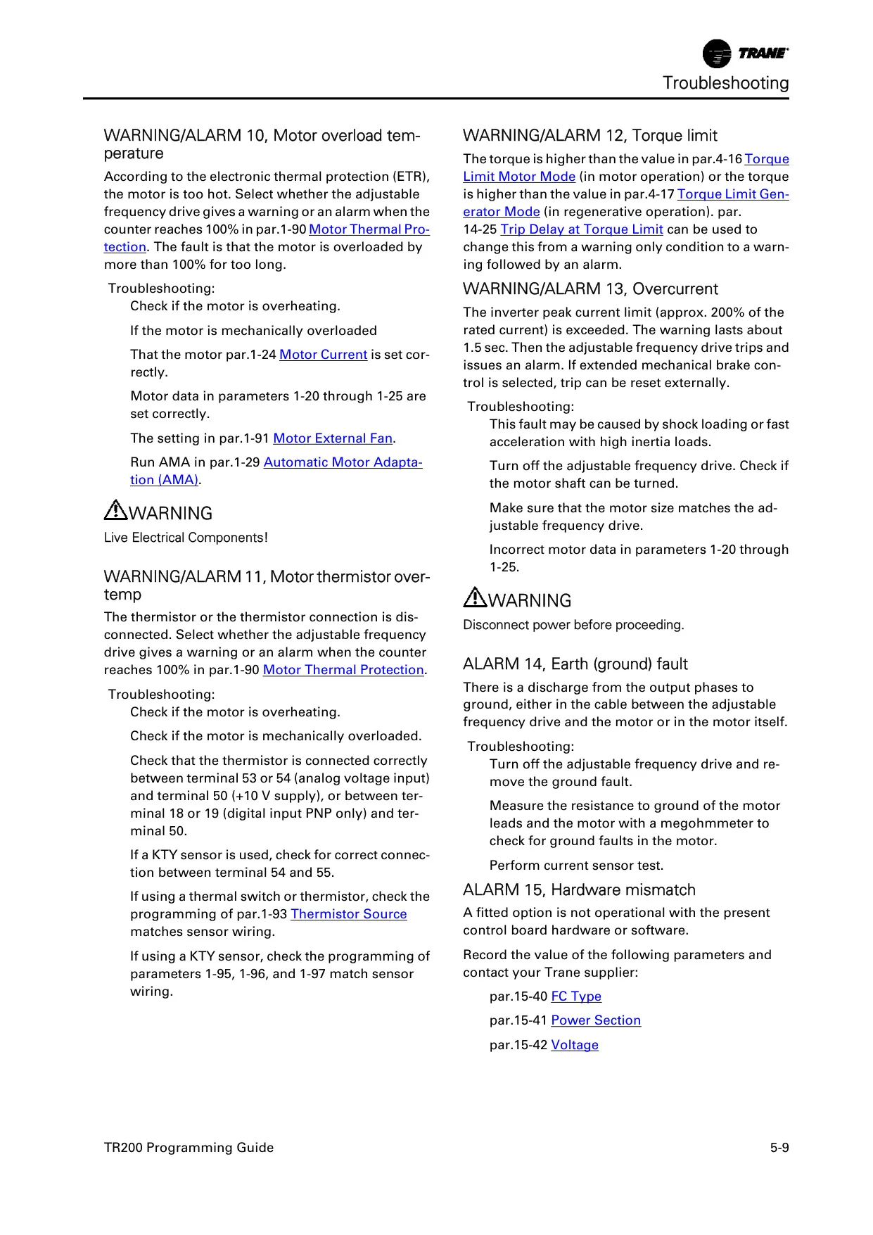
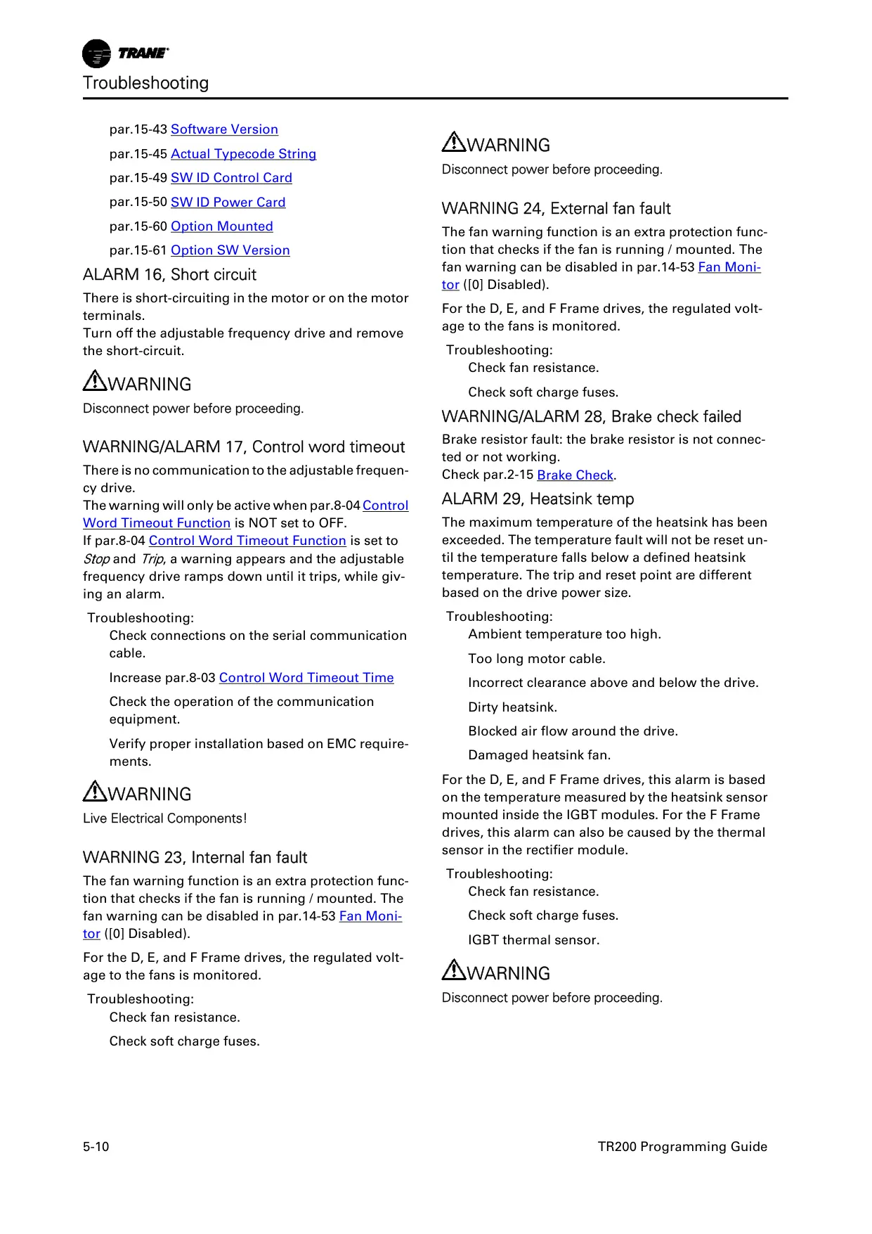
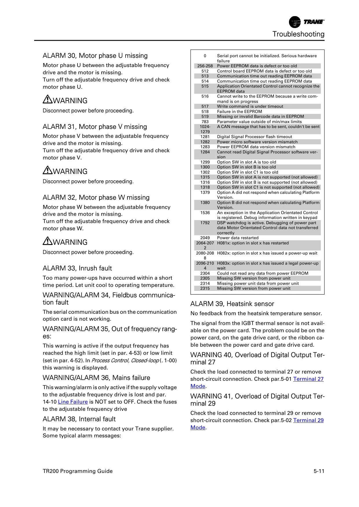
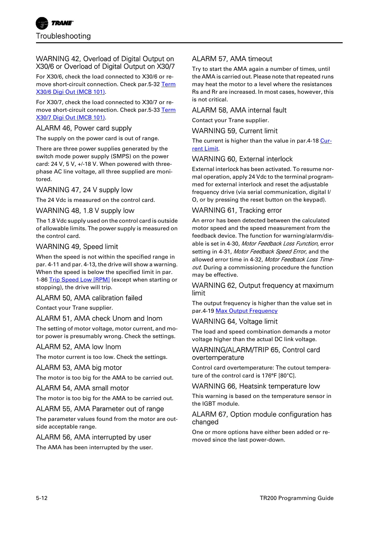
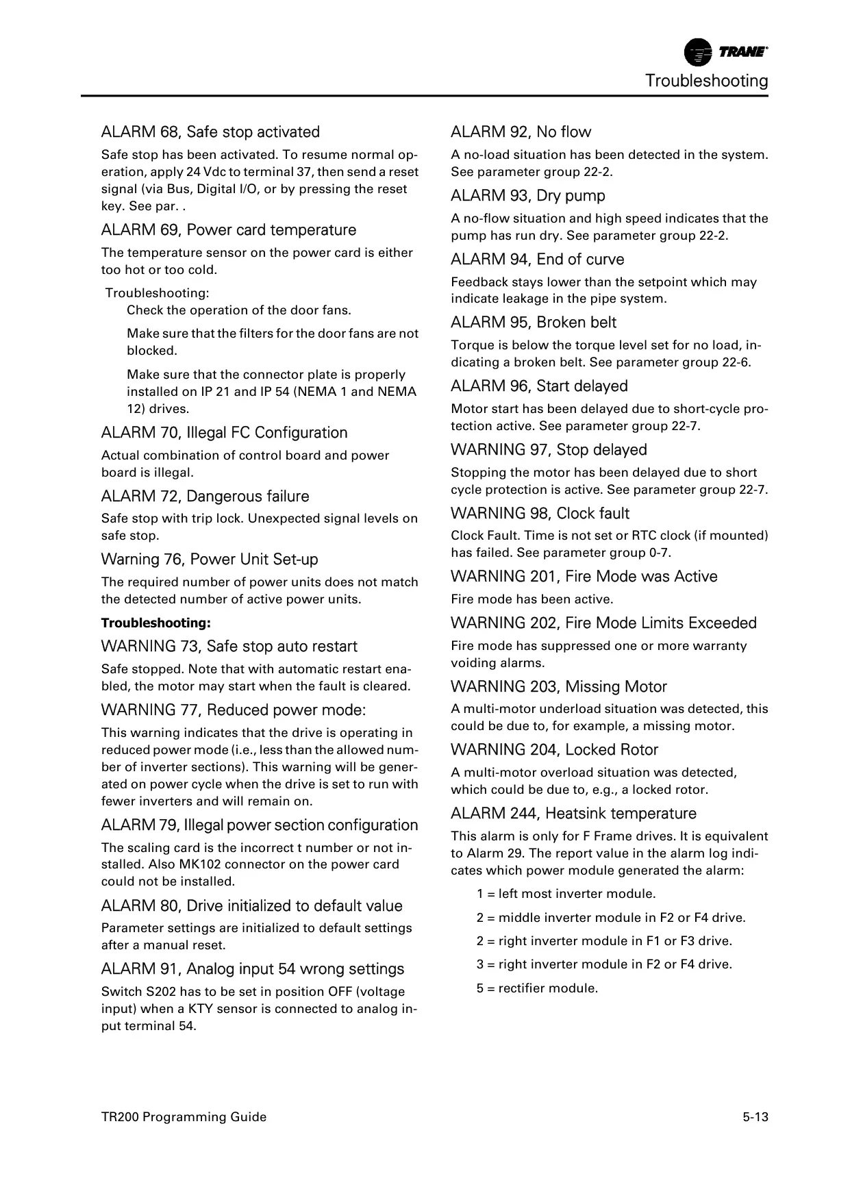
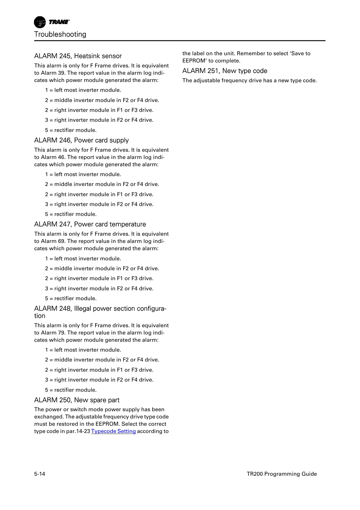
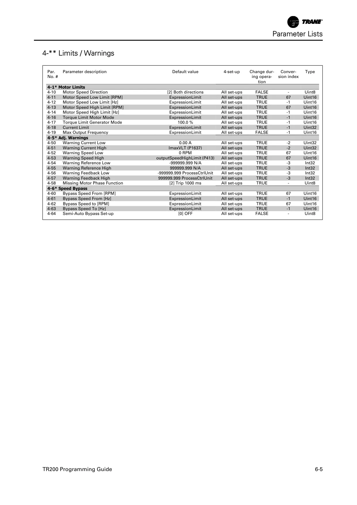
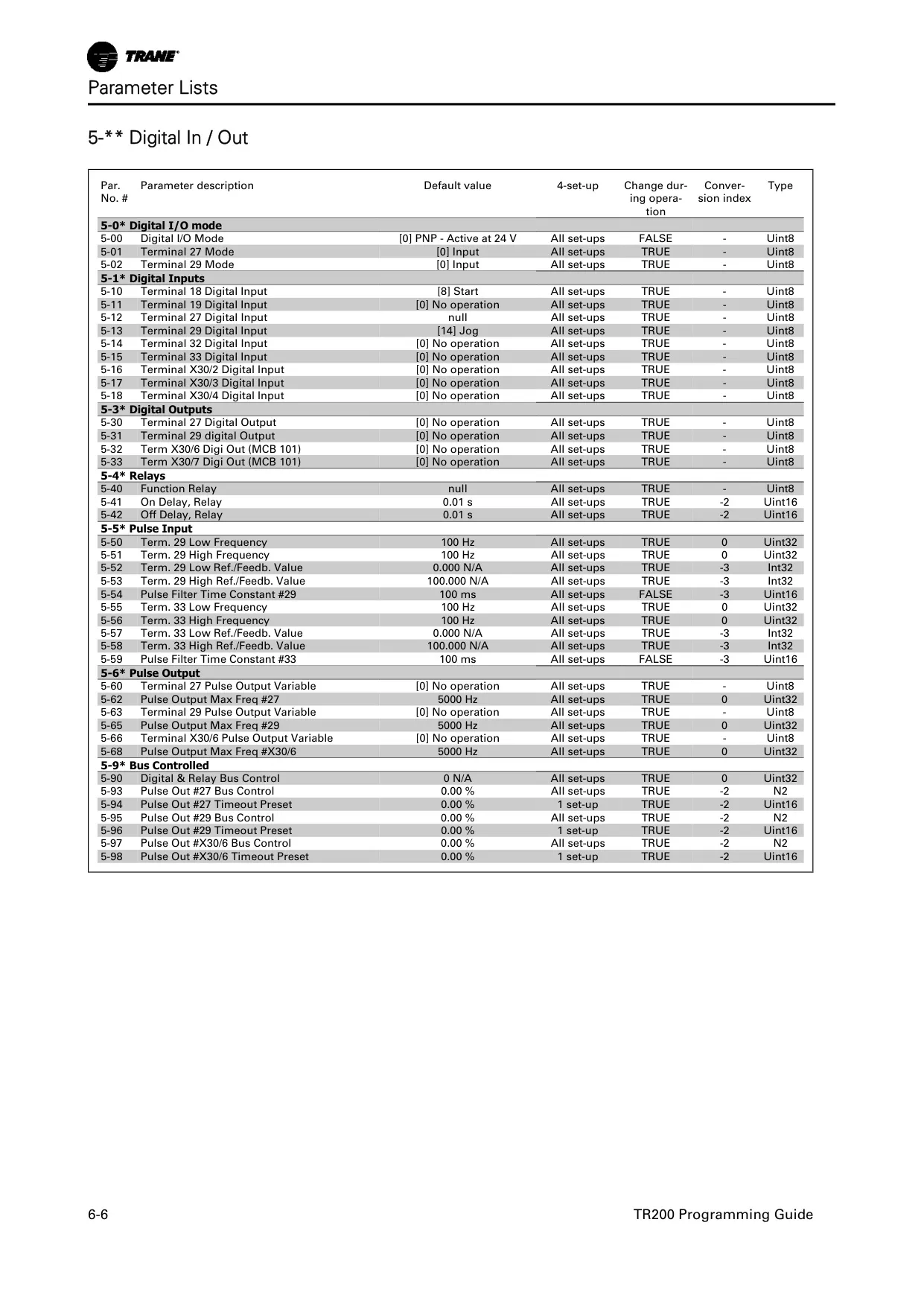
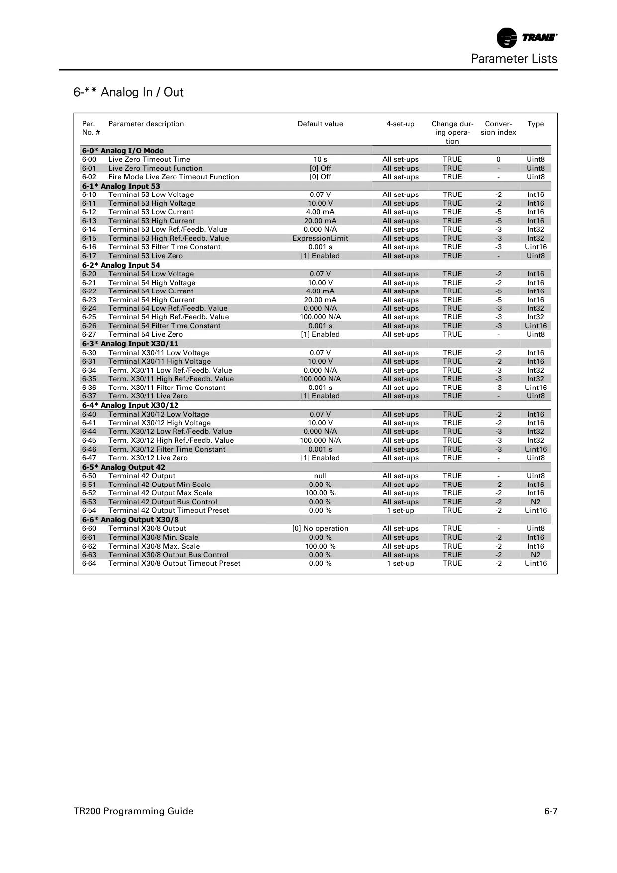
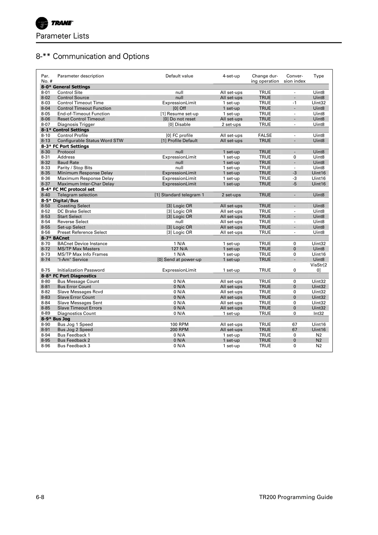
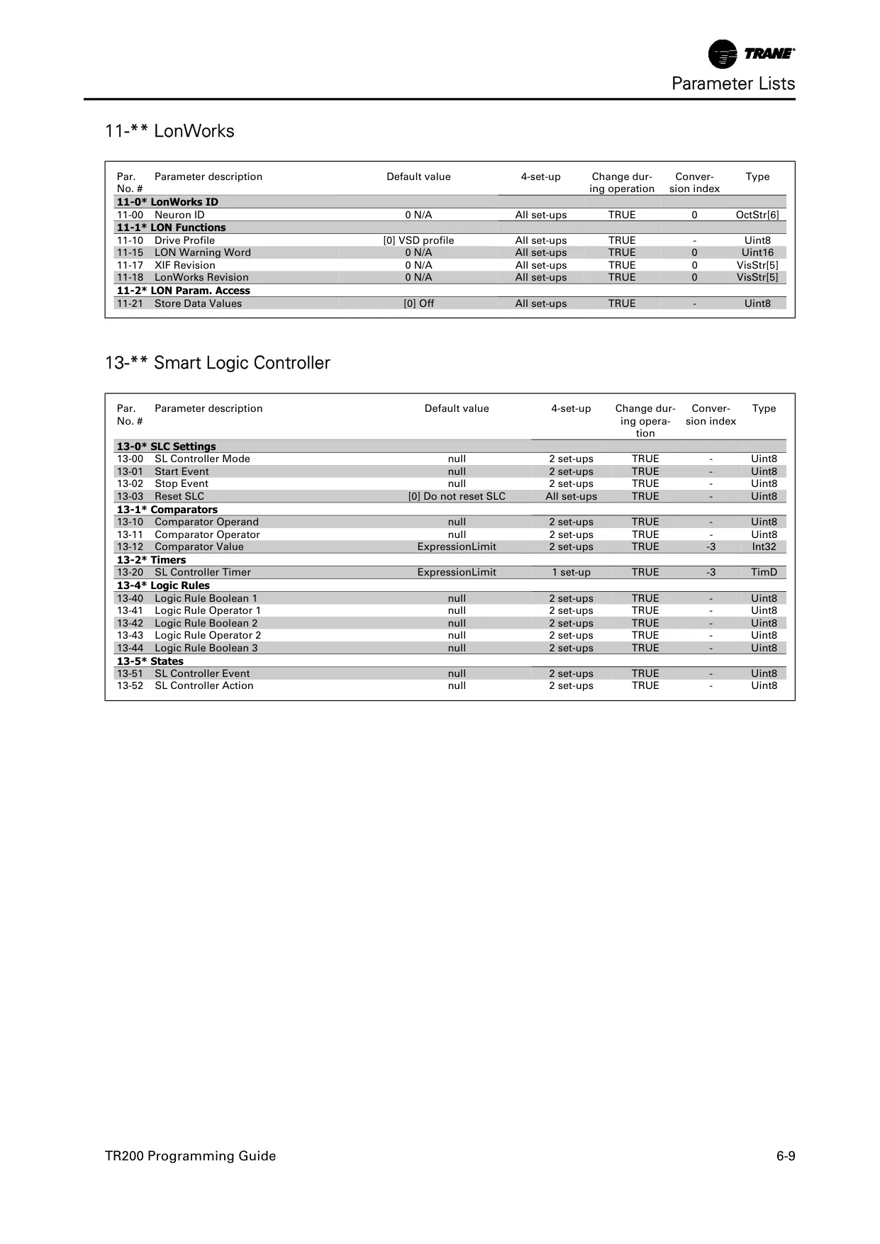
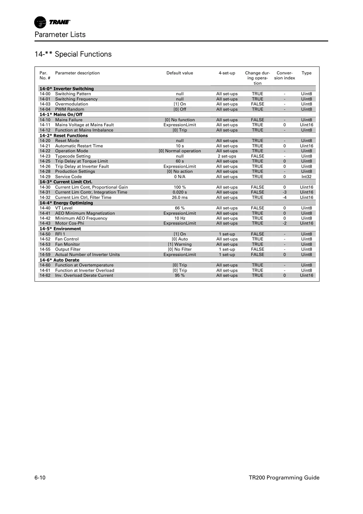

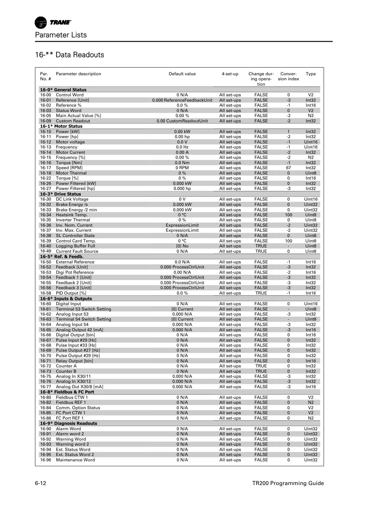
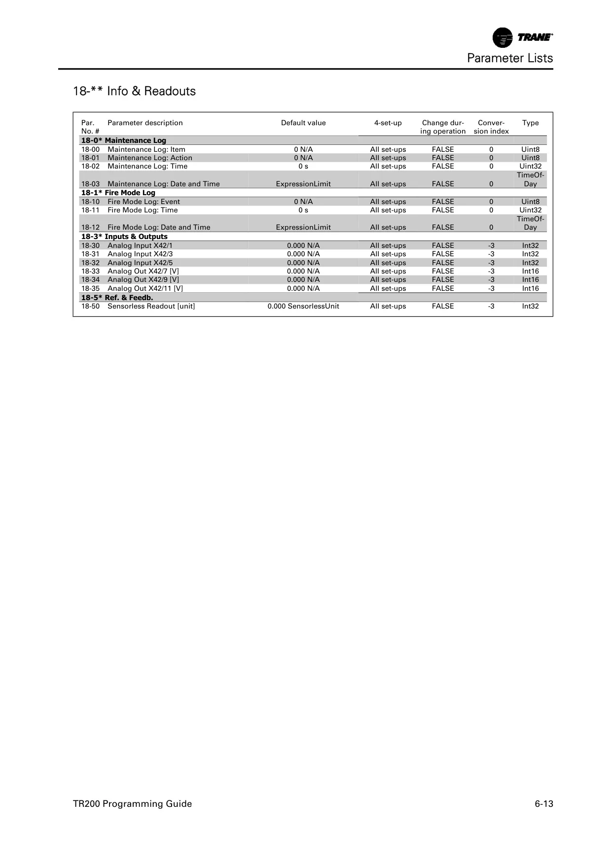
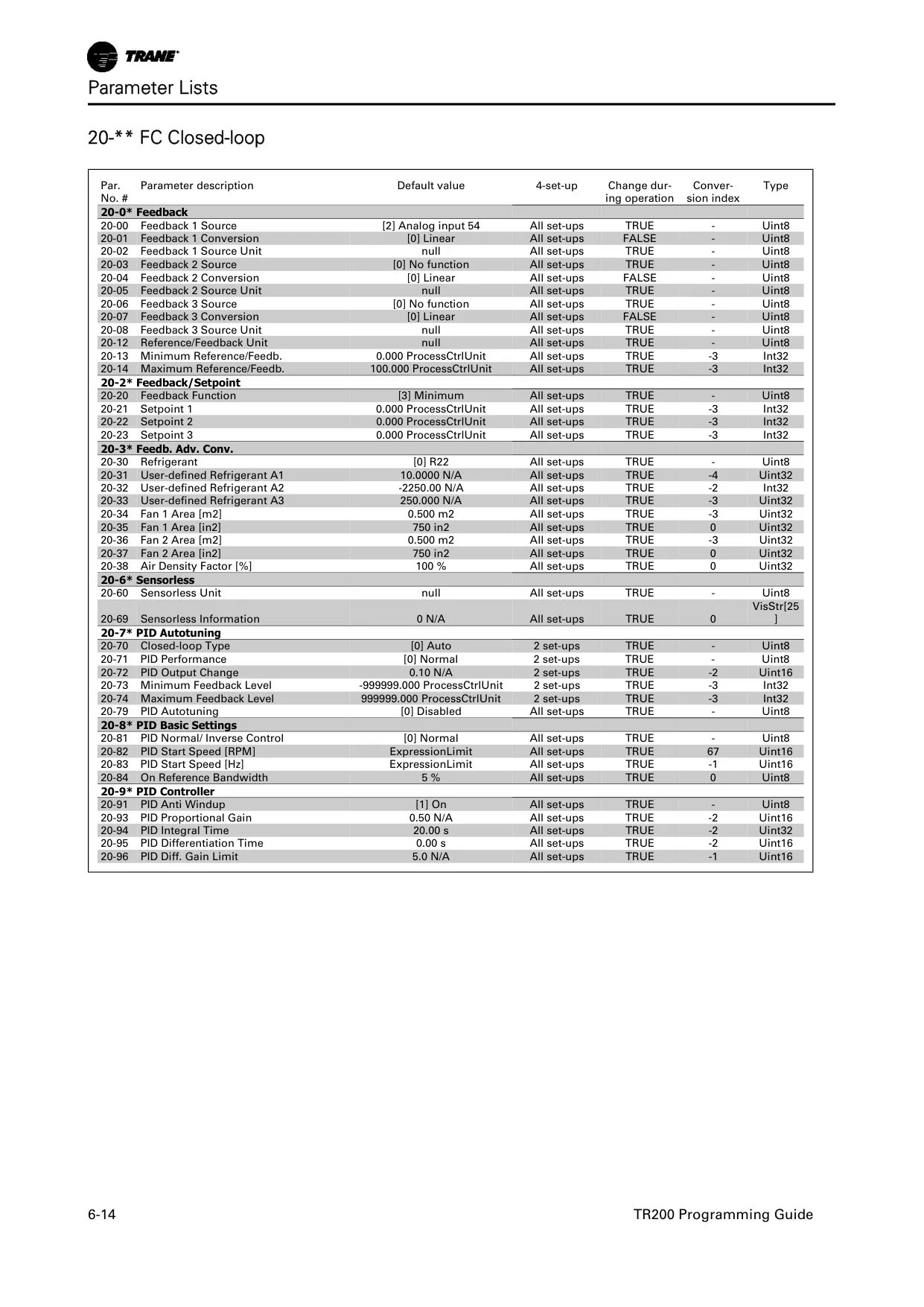
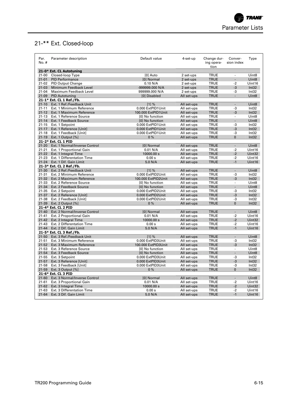
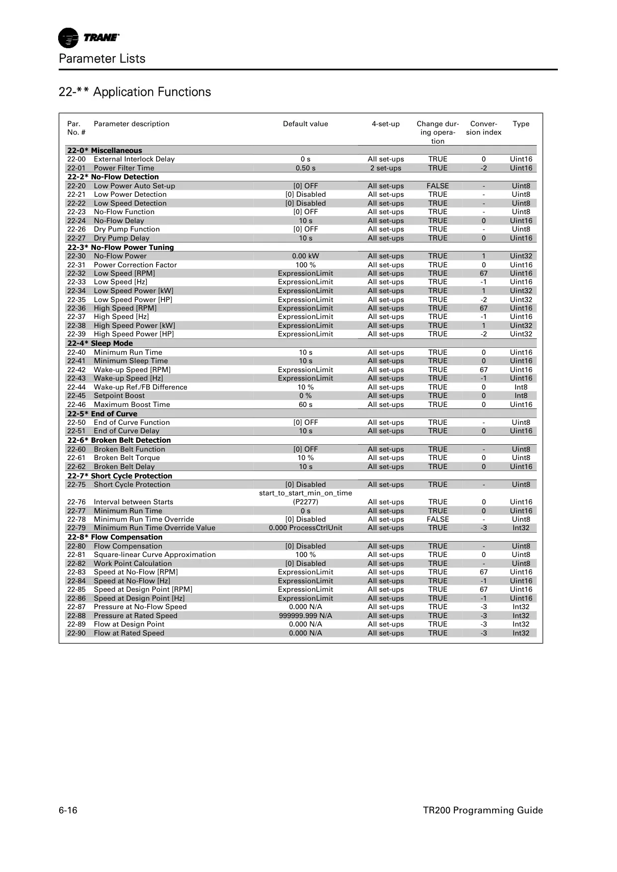
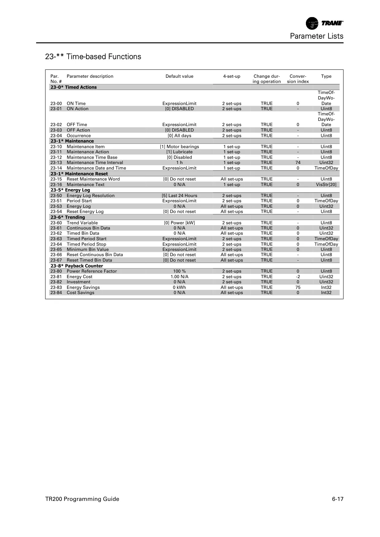
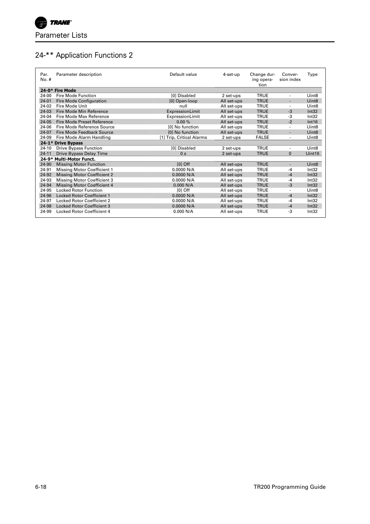
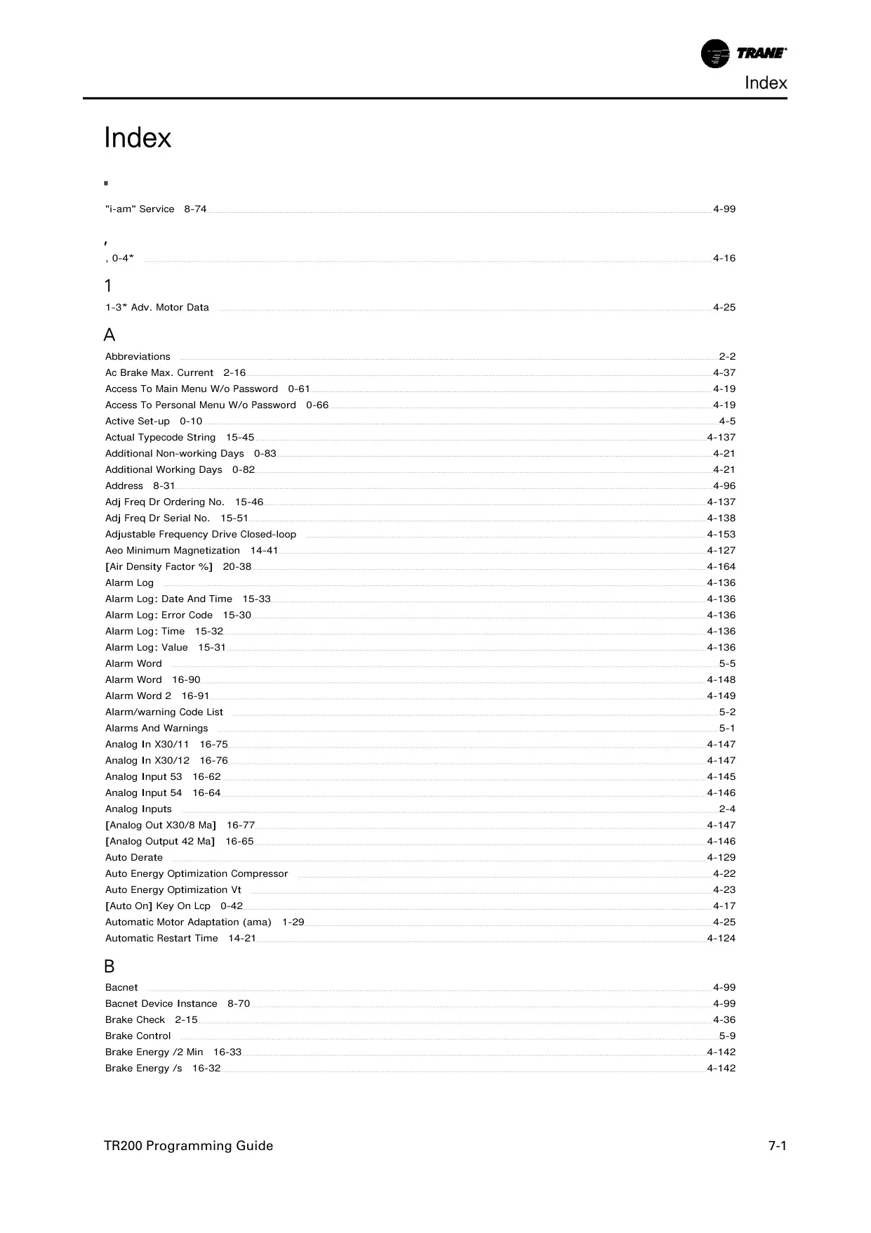
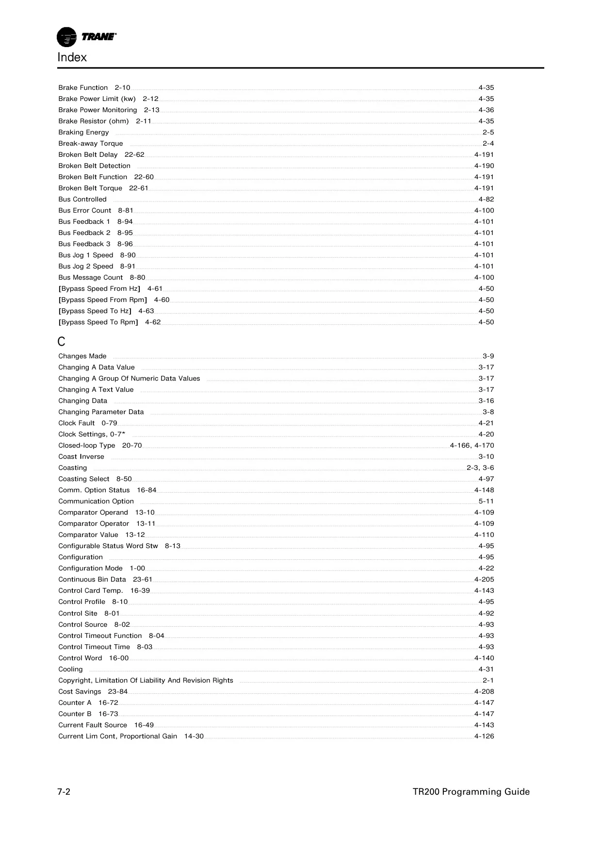
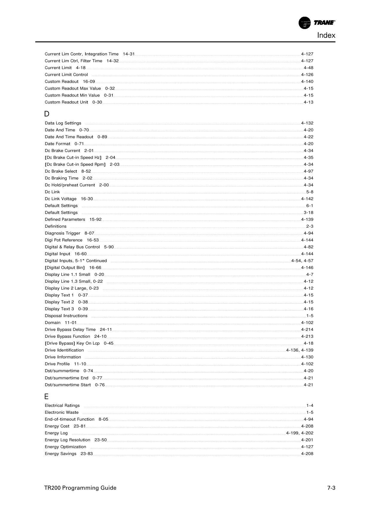
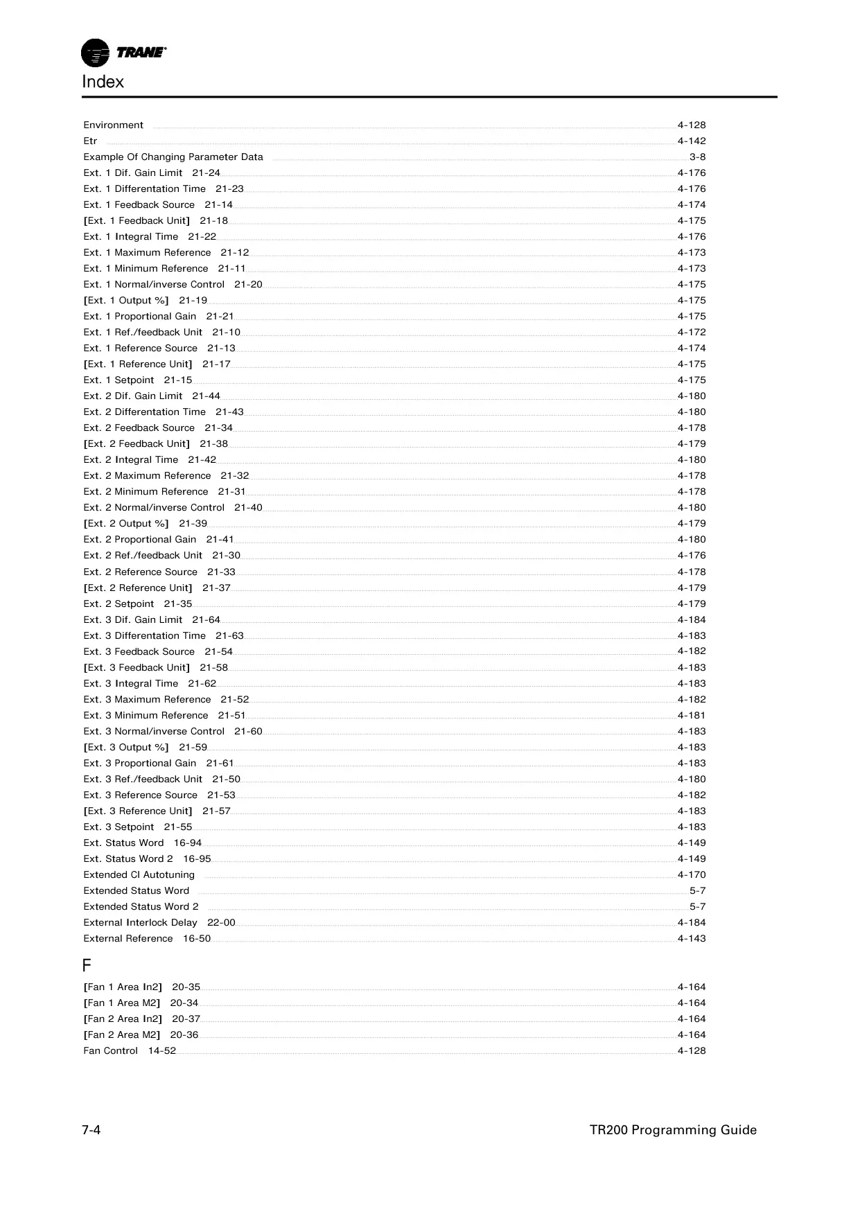
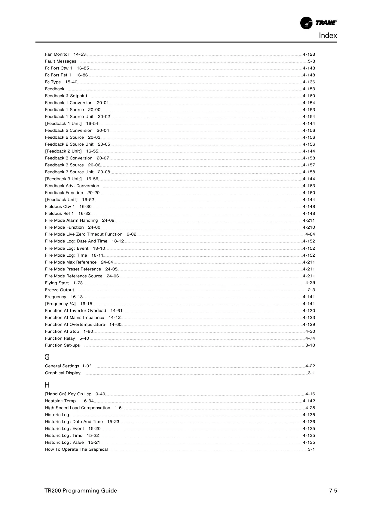
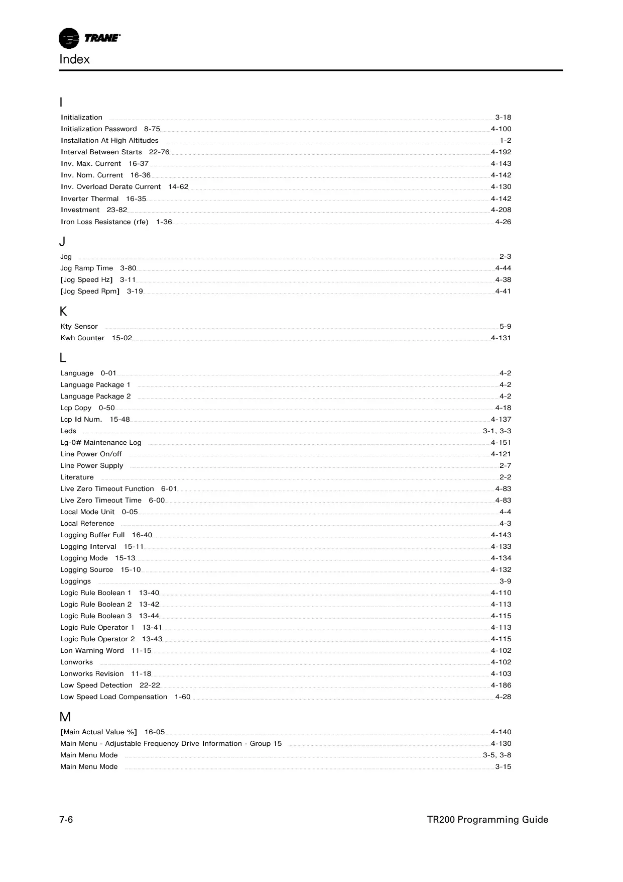
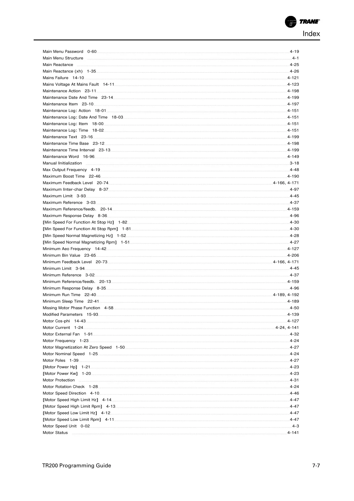
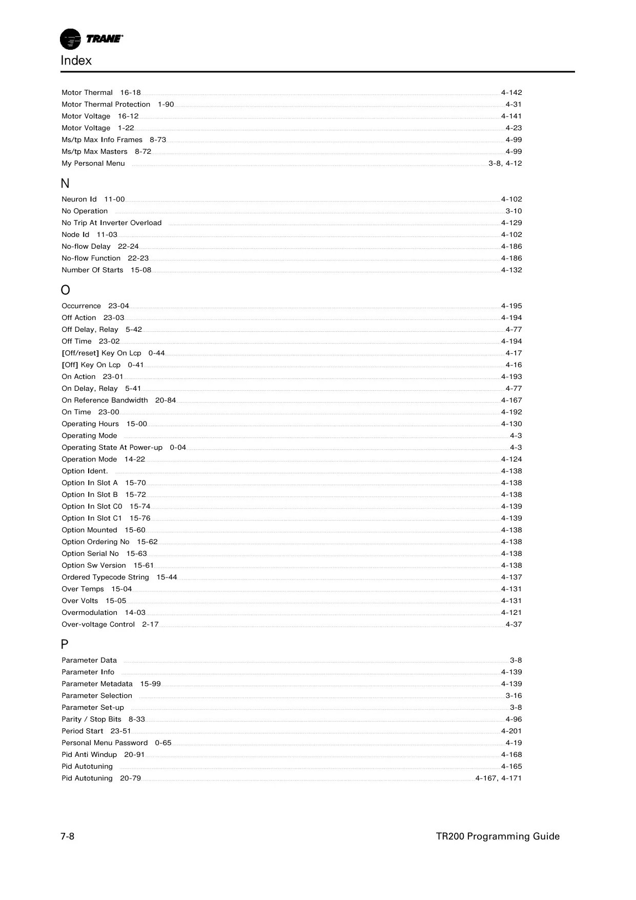
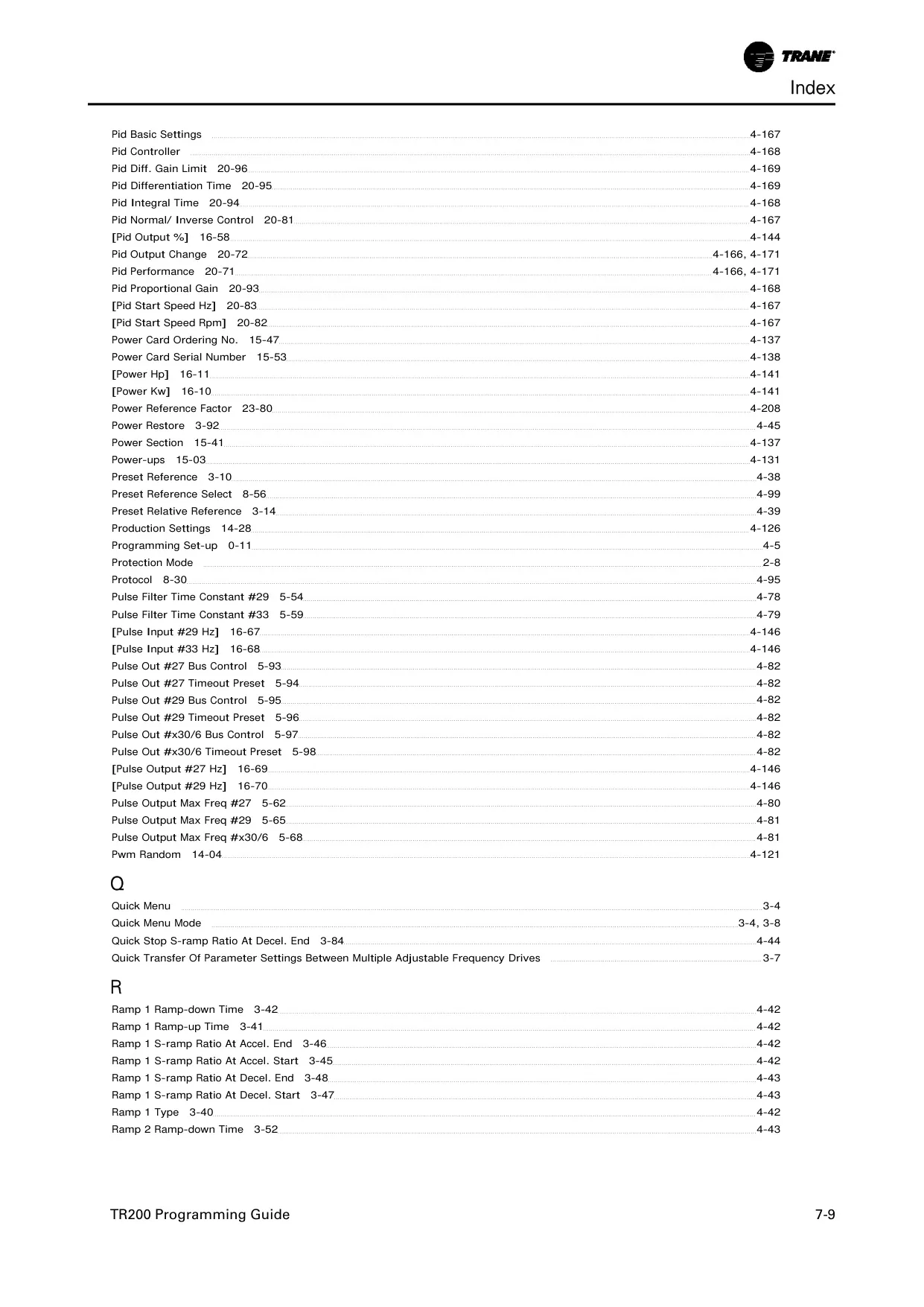
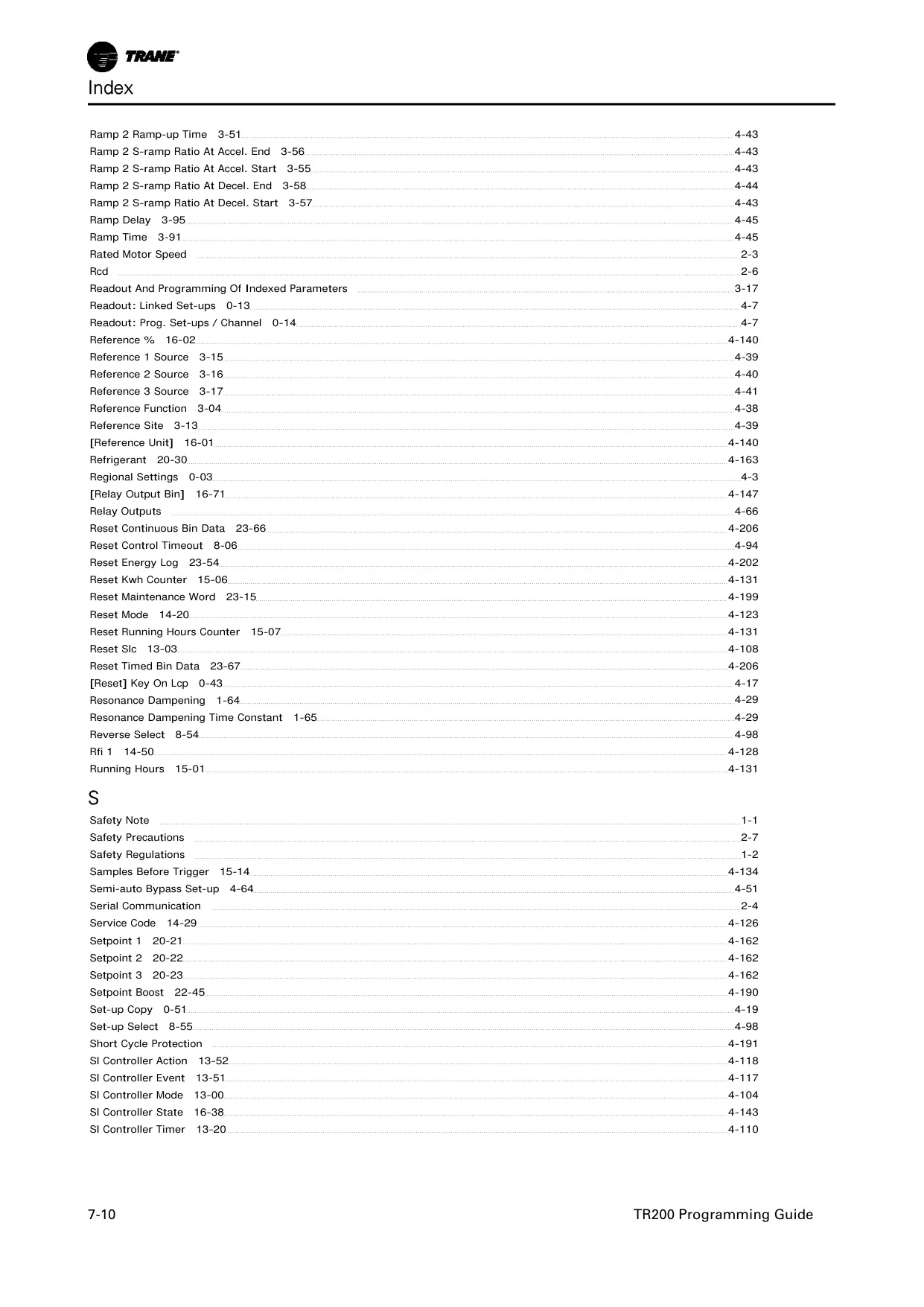
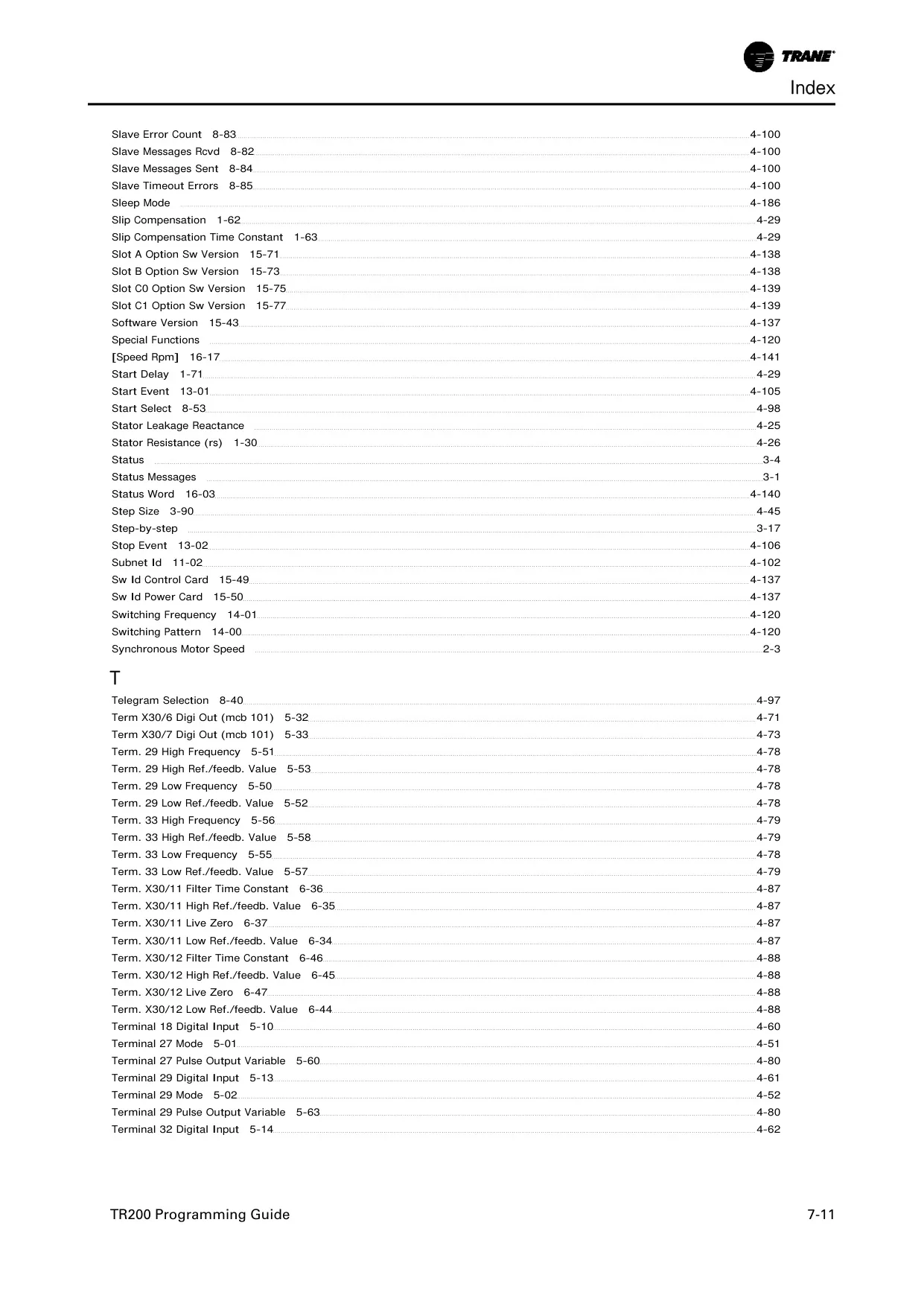
Trane TR200 VFD Instructions
Here we offer the Trane TR200 Variable Frequency Drive manual completely free and in English. We have cataloged this manual in the Variable Frequency Drives section on Manualverse, and it has been rated by 1 users with an average rating of 5. If you have any specific questions about Trane TR200 Variable Frequency Drive, we suggest checking the Frequently Asked Questions (FAQs) section of this manual.
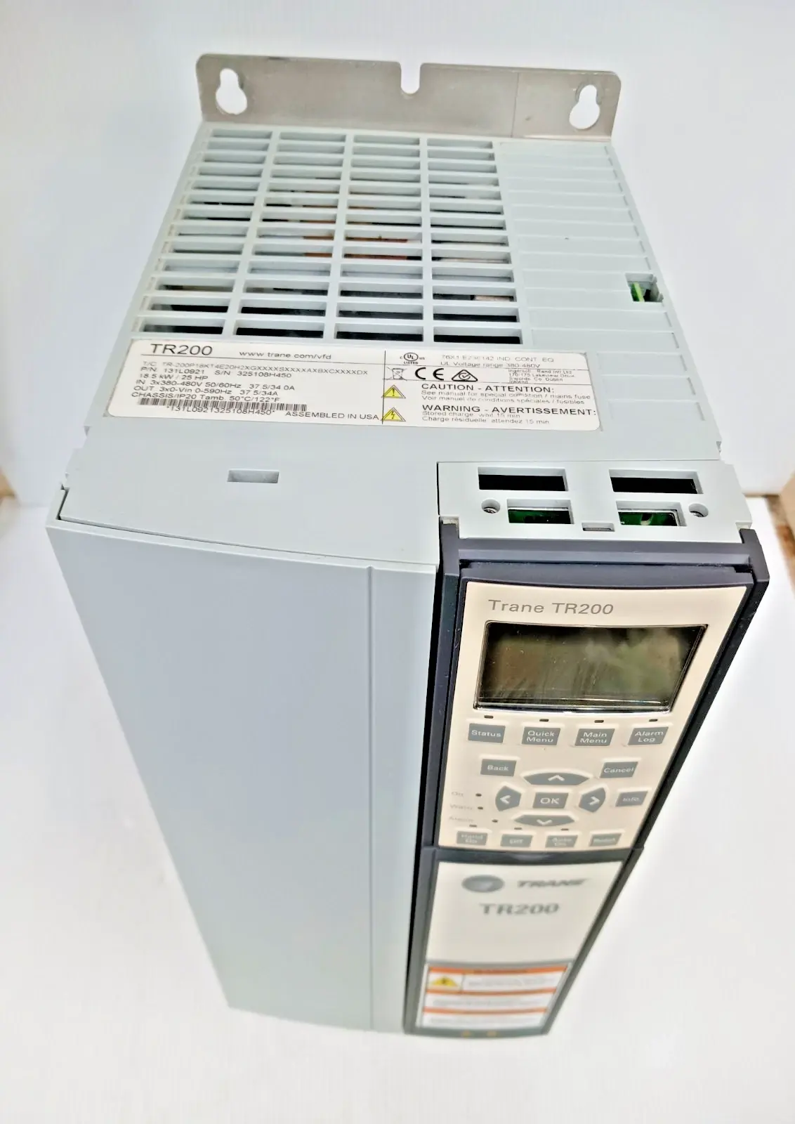
Product Images
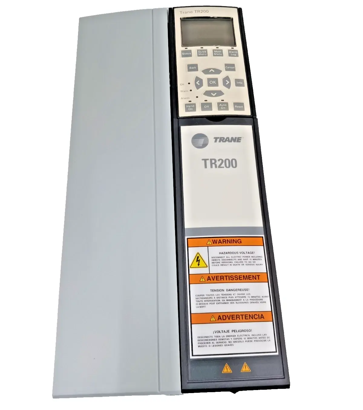


Trane TR200 Variable Frequency Drive Specifications
| Feature | Specification |
|---|---|
| Product Name | Trane TR200 VFD |
| Manual Title | APOGEE® Communications Protocol Operating Instructions |
| Software Version | 1.1.x |
| Communication Protocol | Siemens Floor Level Network (FLN) |
| Communication Interface | RS-485, Half Duplex |
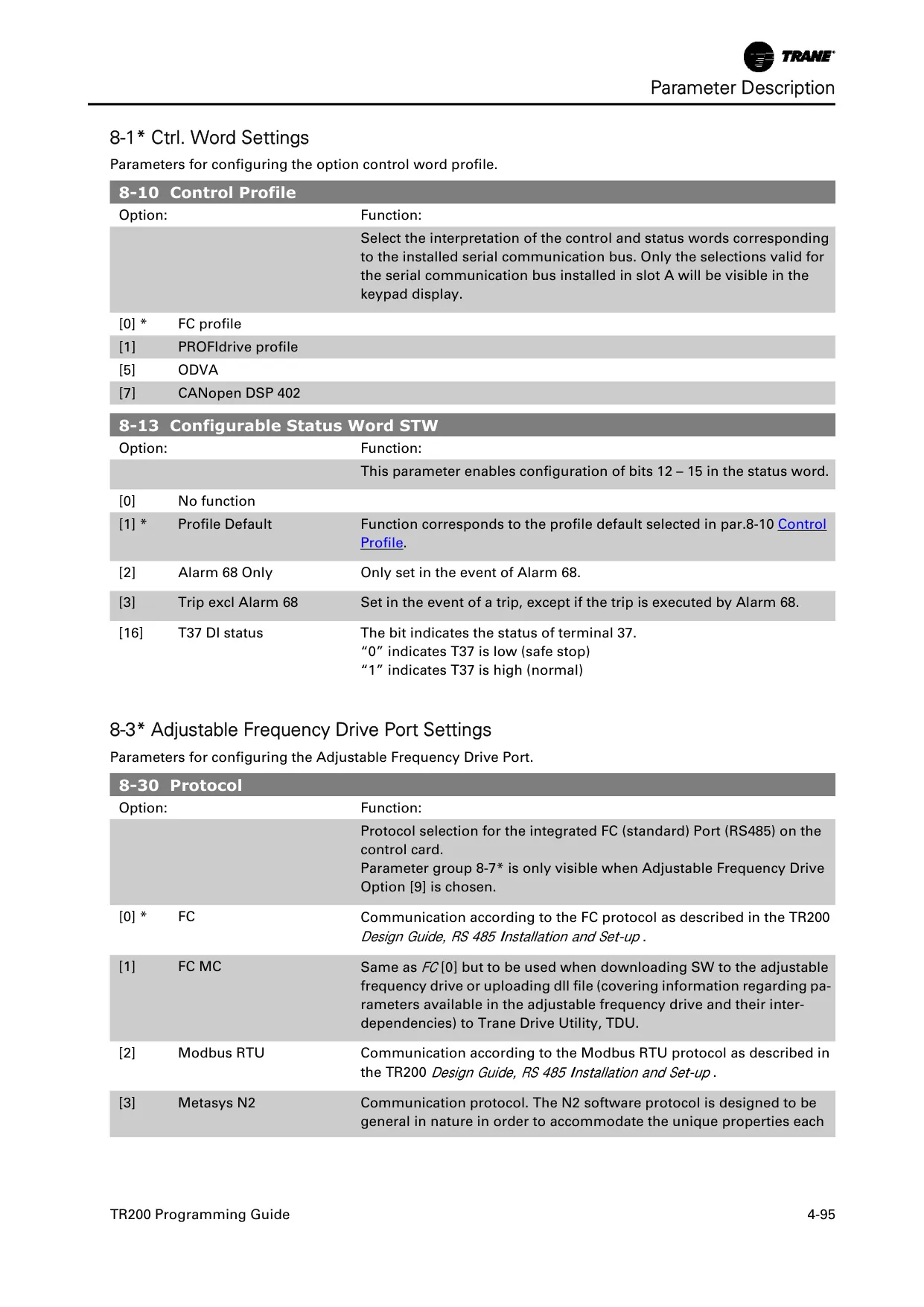
| Supported Baud Rates | 4800 or 9600 baud |
| Maximum FLN Devices | Up to 96 devices per system |
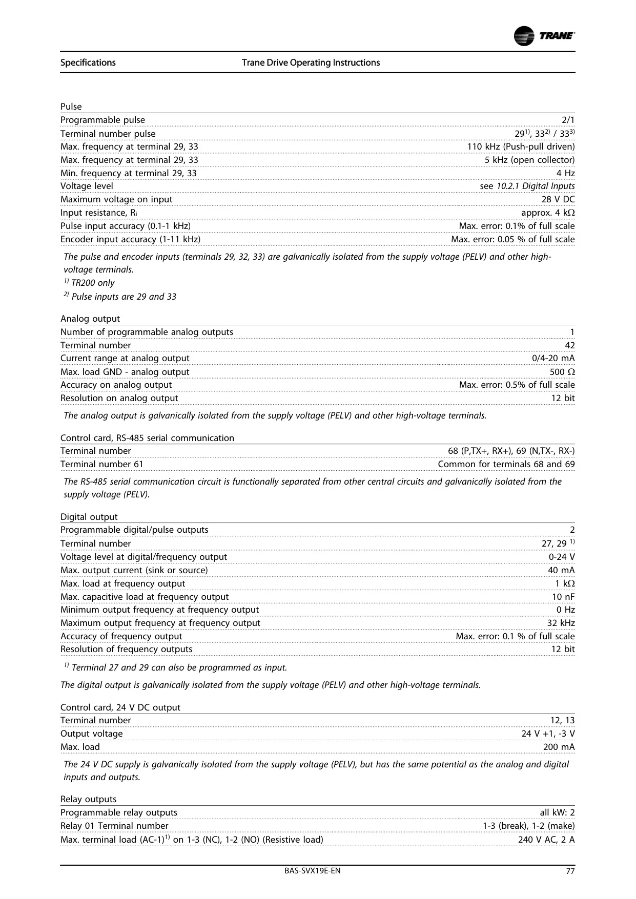
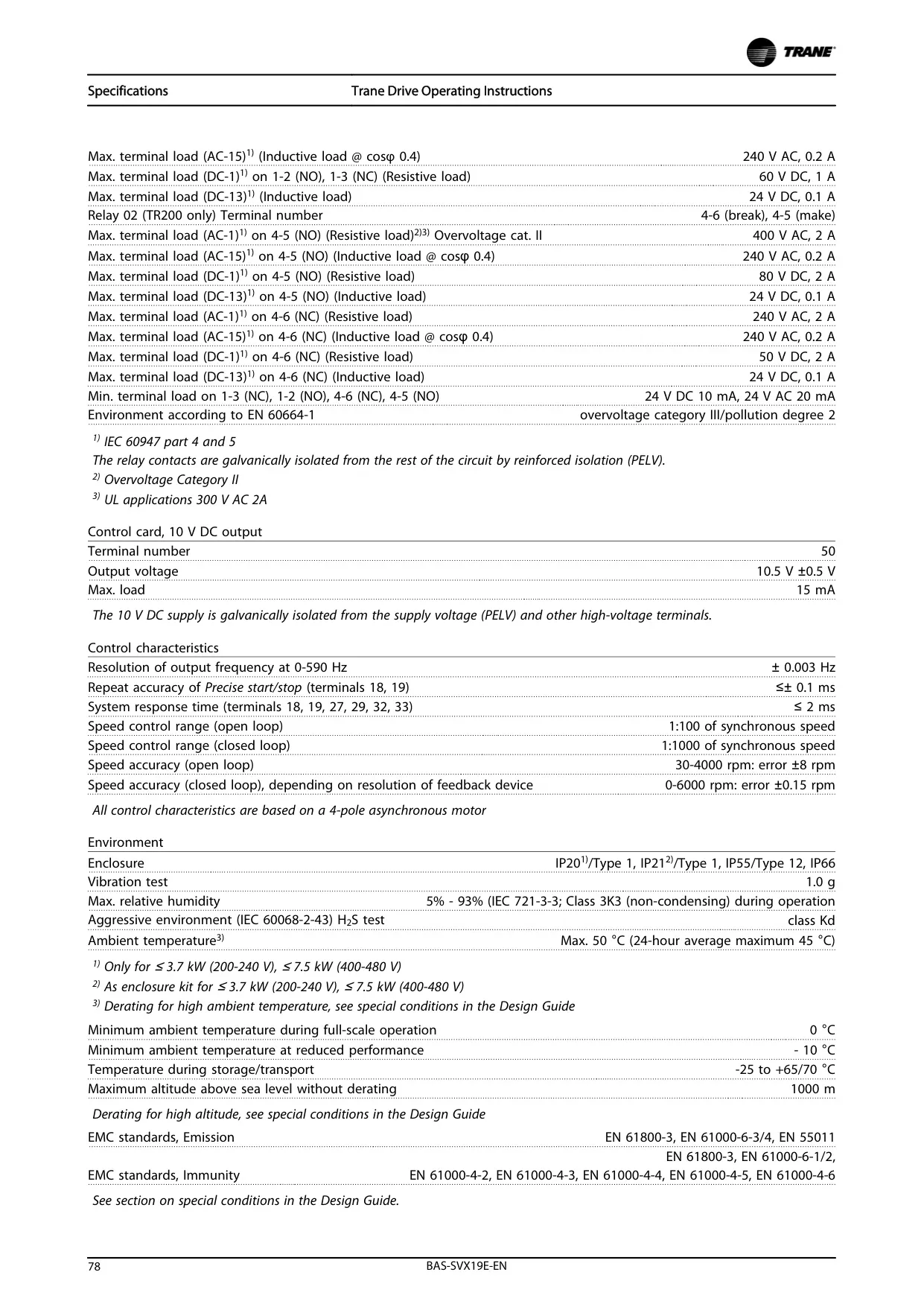
| Relay Outputs | 2 programmable, Form C, 240 VAC, 2 Amp |
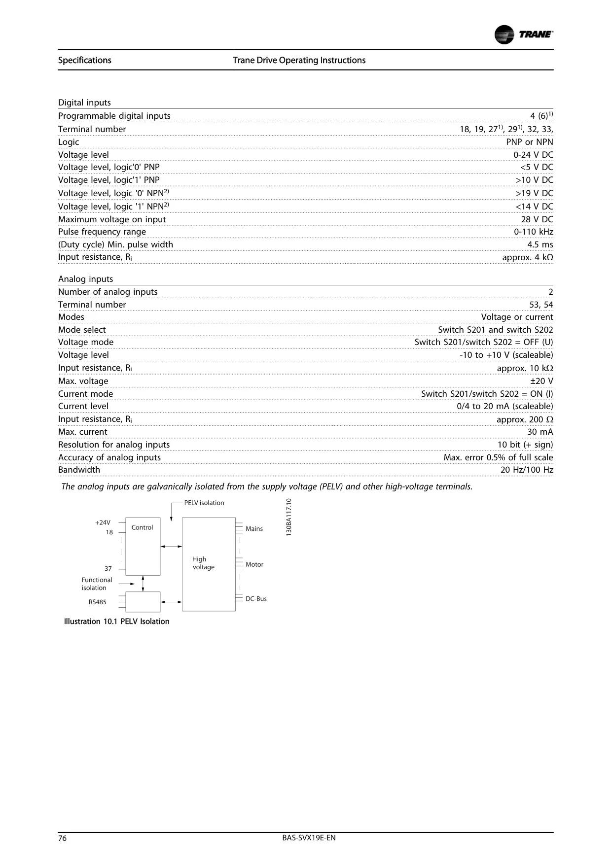
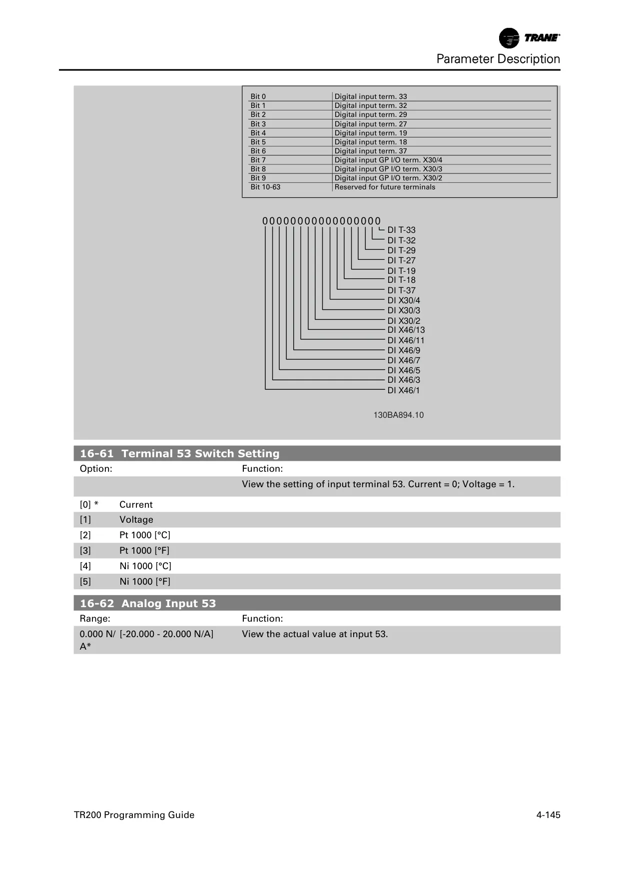
| Analog Inputs (Terminals 53, 54) | 0–10 VDC / 0–20 mA |
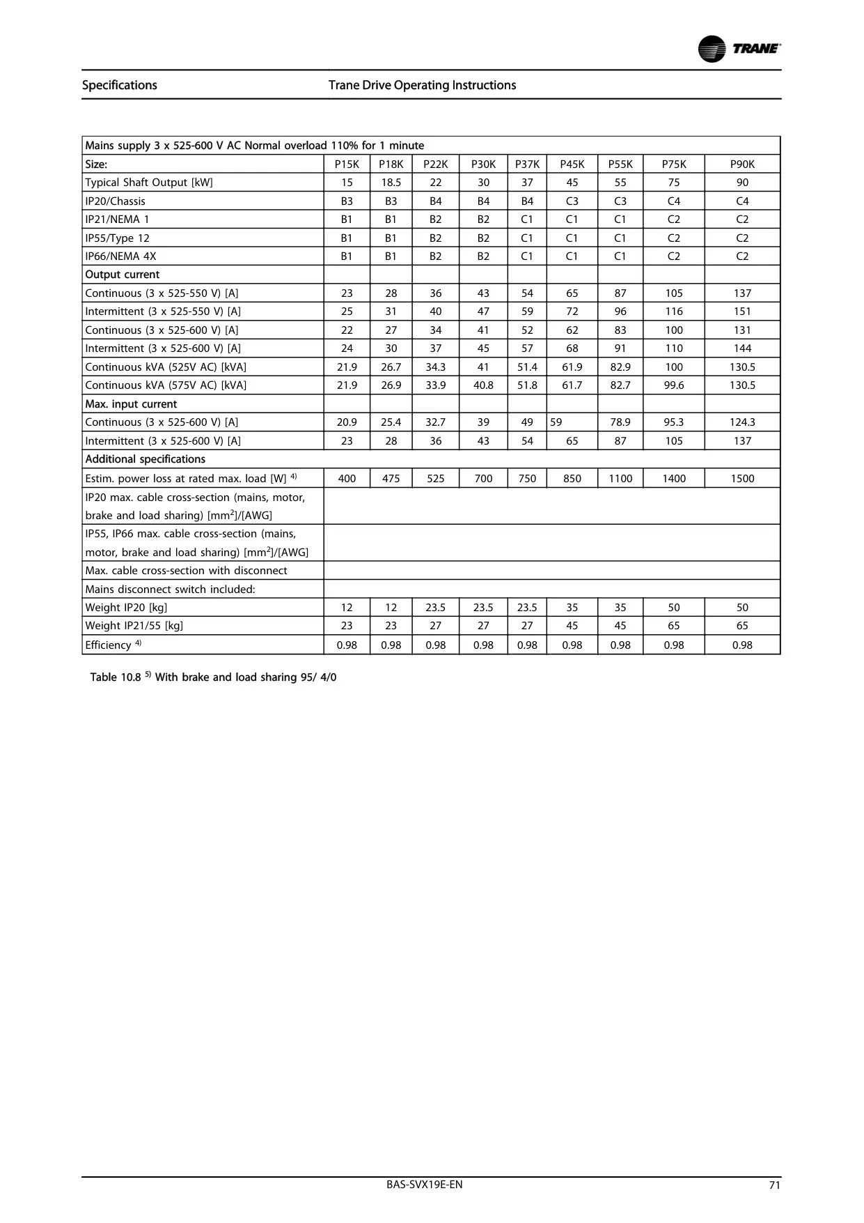
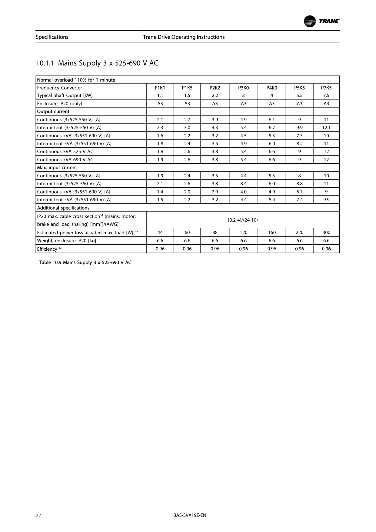
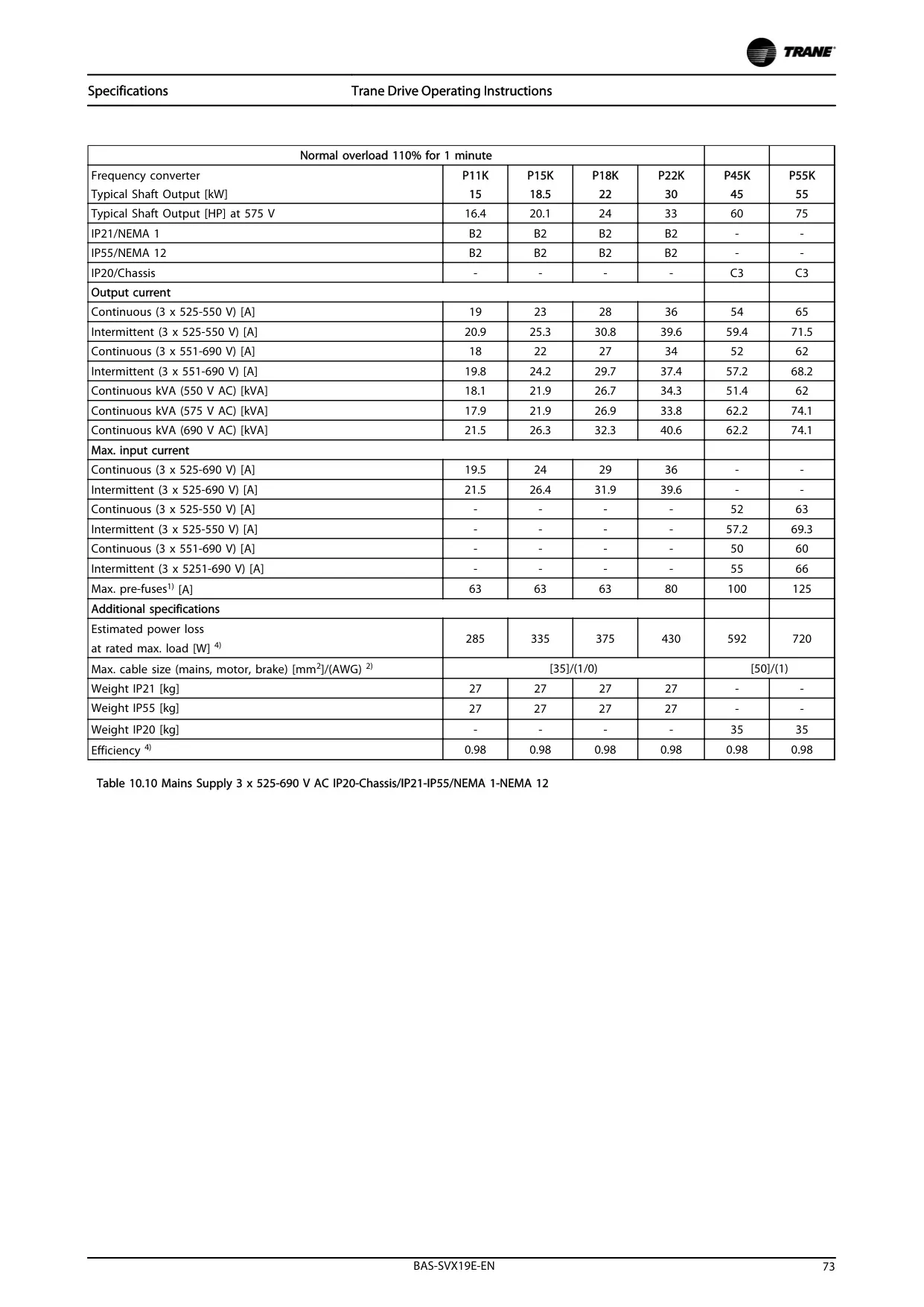
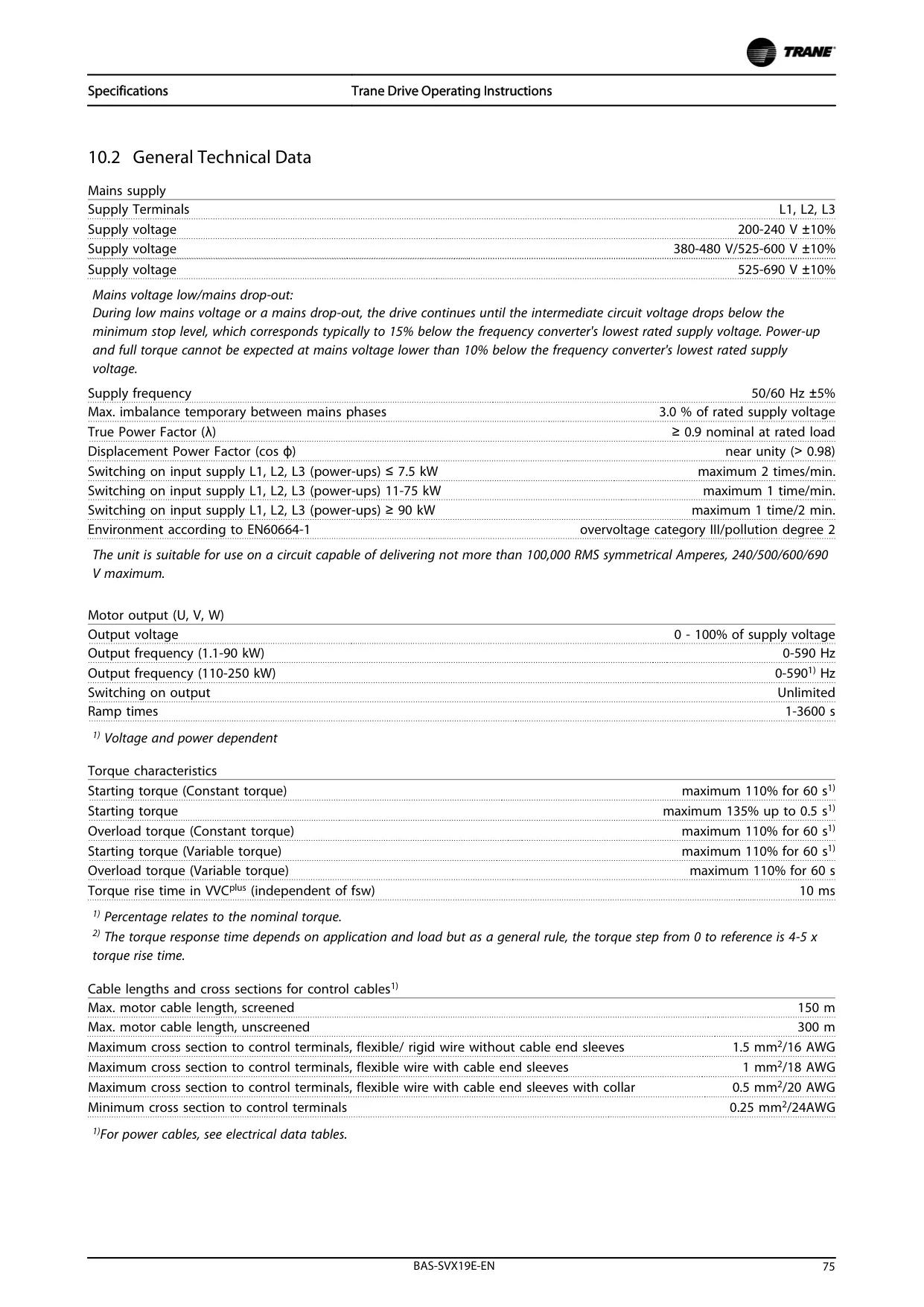
| Nominal Voltage Ranges | 200-240V, 380-480V, 525-600V, 525-690V |
| Output Frequency Range | Programmable (e.g., Ramp-up/down from 0 Hz to nominal) |
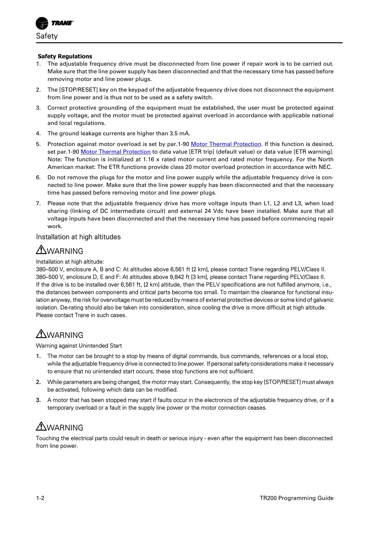
| Motor Overload Protection | Class 20 (ETR trip/warning) |
| Altitude Derating (380-500V, A, B, C enclosure) | Above 6,561 ft (2 km) requires consultation |
| Altitude Derating (380-500V, D, E, F enclosure) | Above 9,842 ft (3 km) requires consultation |
Trane TR200 VFD Details
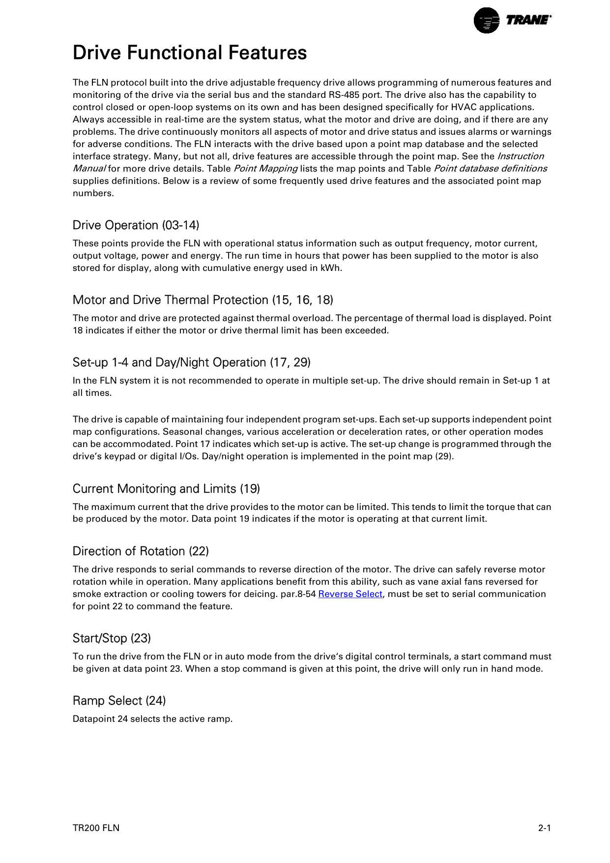
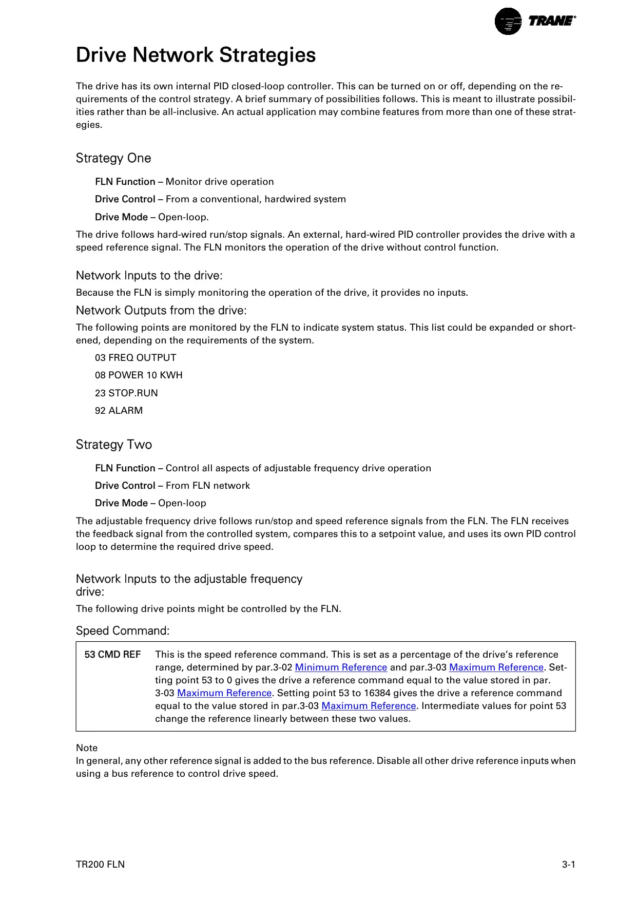
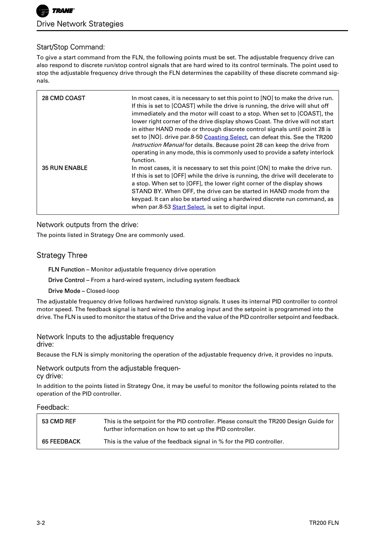
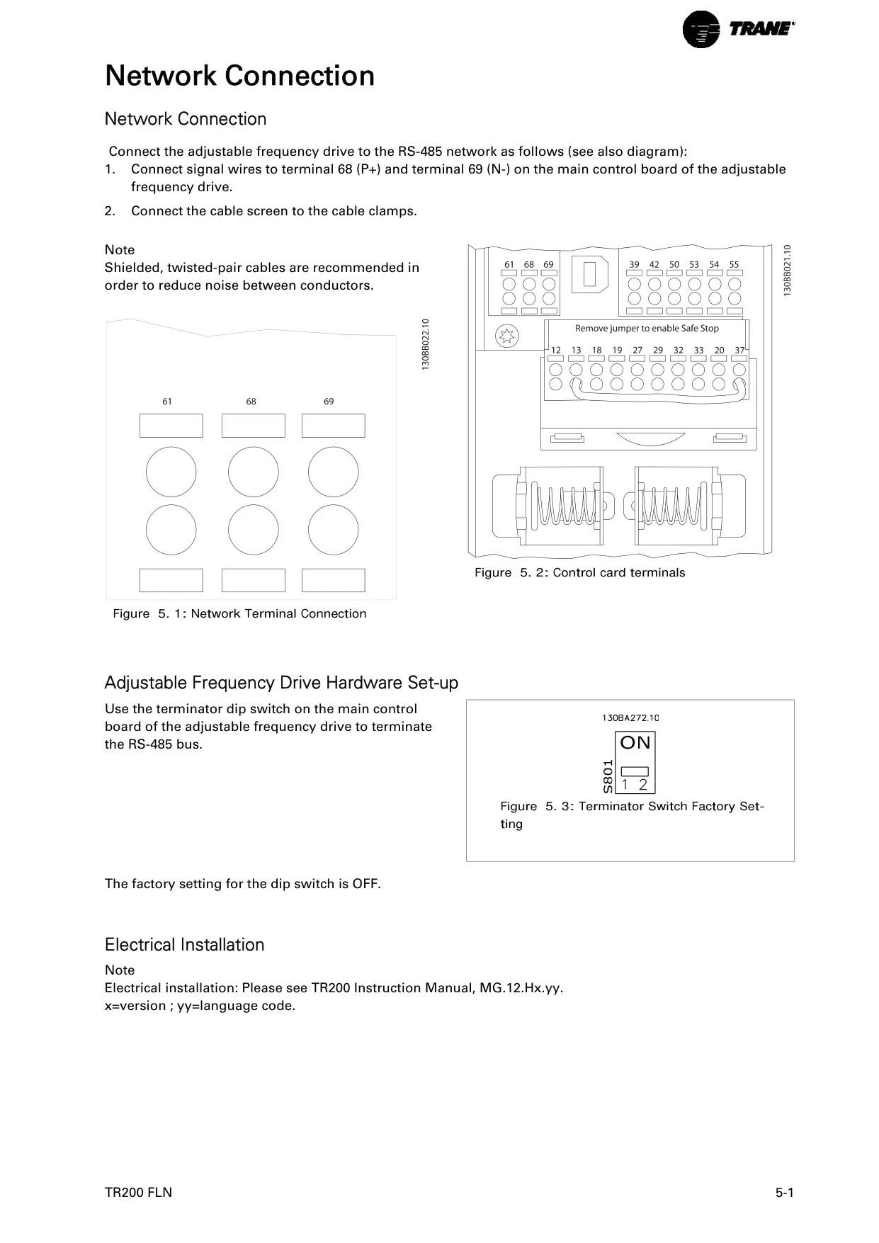
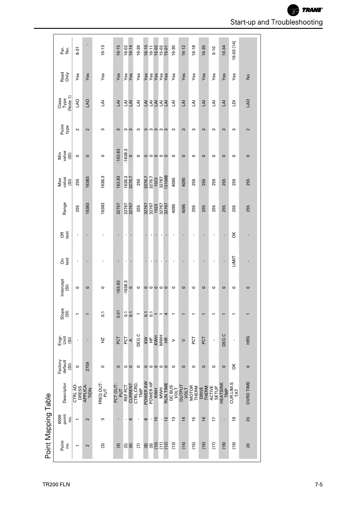
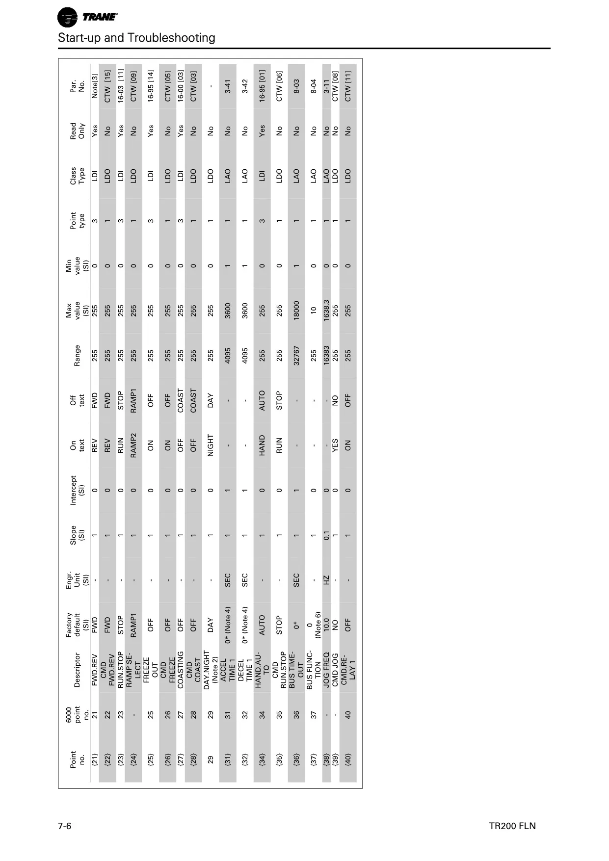
The Trane TR200 VFD is specifically engineered for HVAC applications, seamlessly integrating with the Siemens Floor Level Network (FLN) protocol. This integration allows for comprehensive control and real-time monitoring of the drive's operations via a serial bus, using its standard RS-485 port. Users can access critical system status, motor and drive performance, and diagnostic information, including energy consumption in kWh and total operating hours.
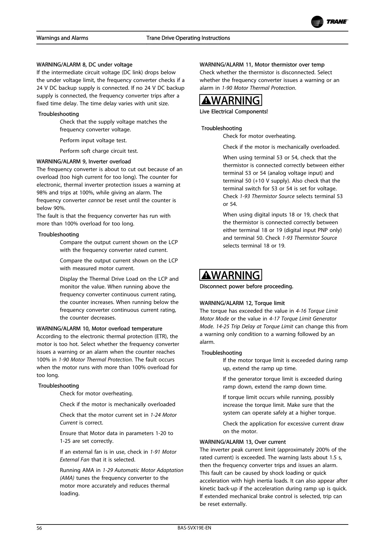
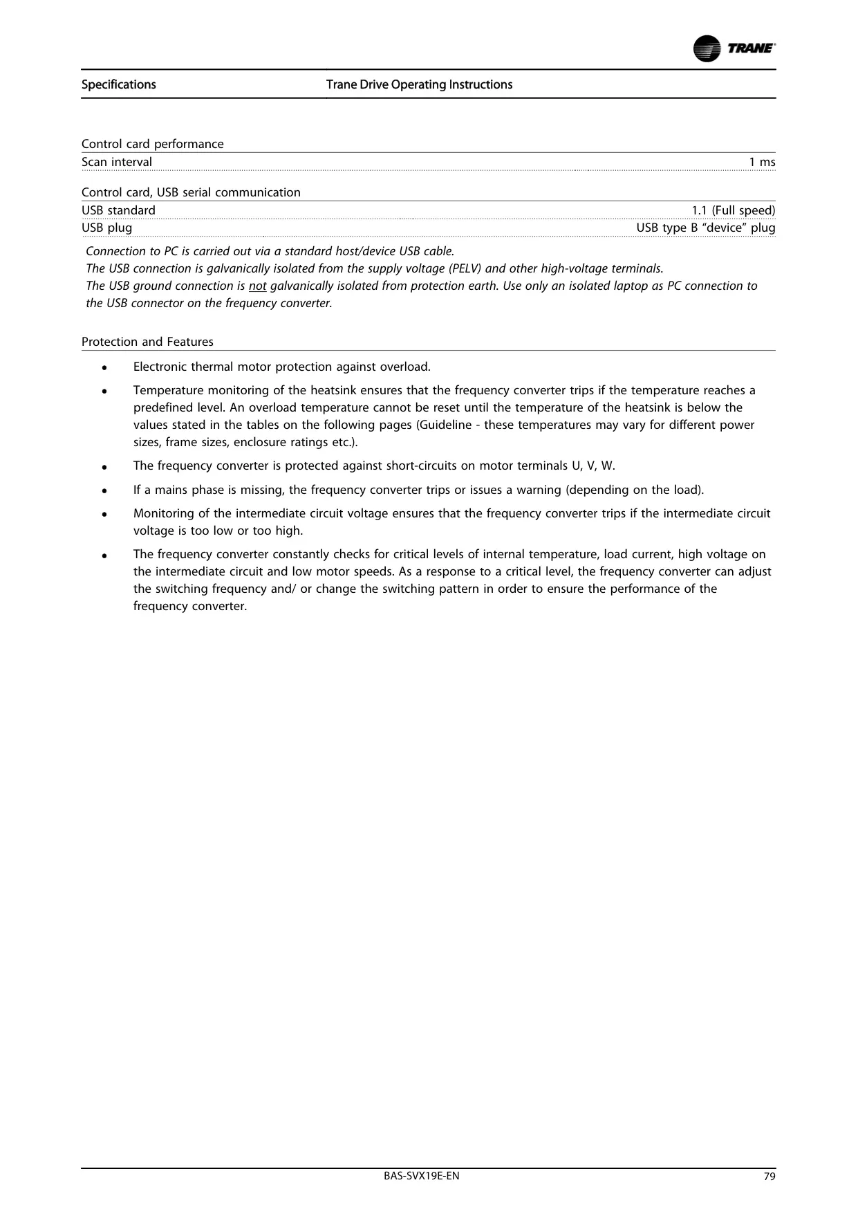
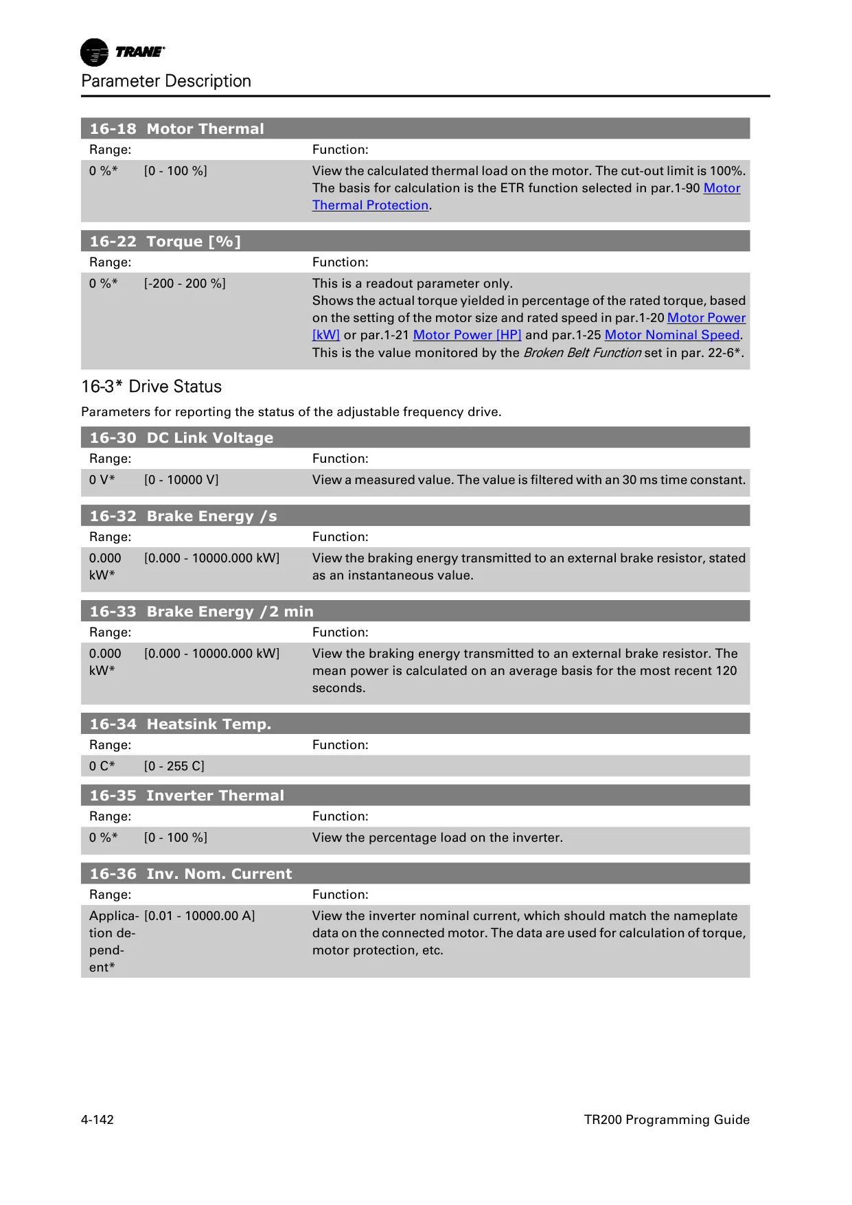
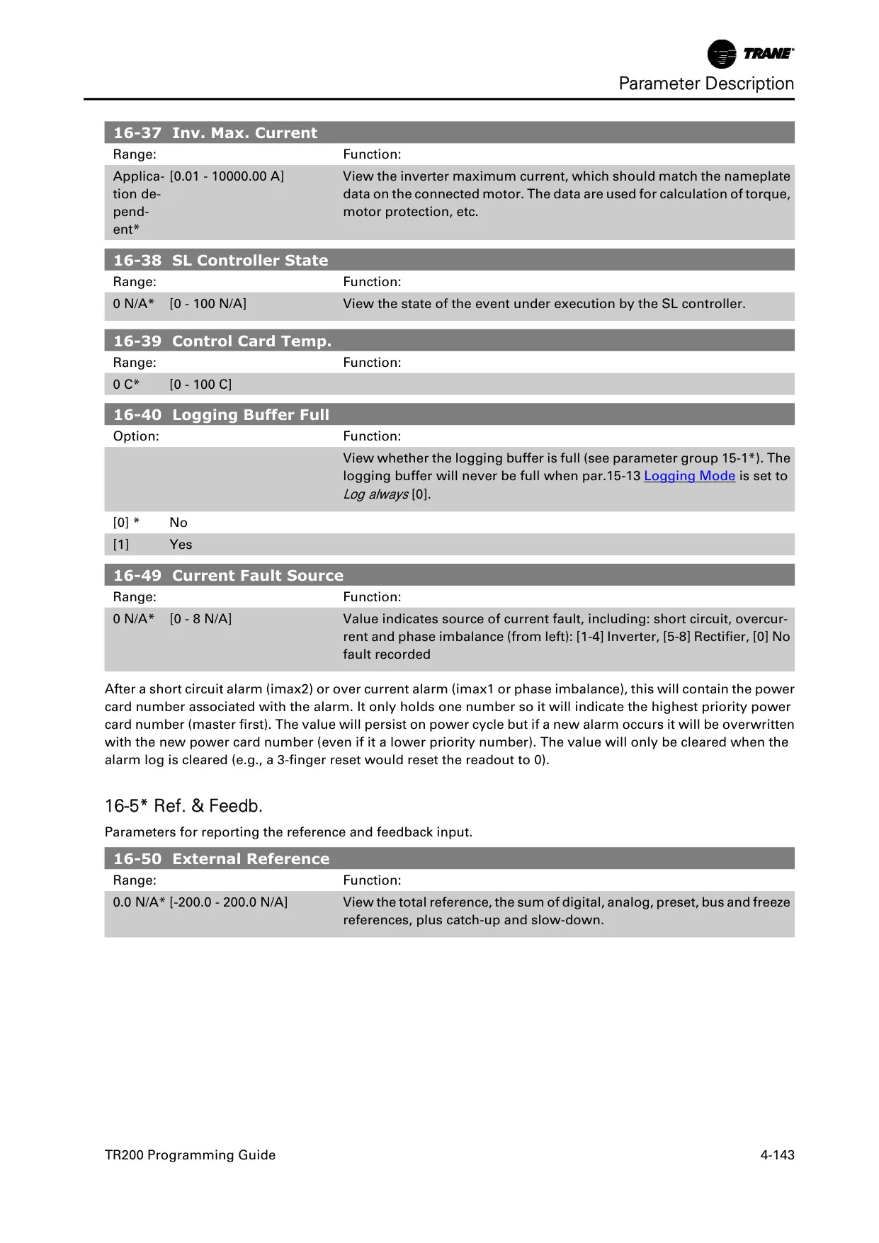
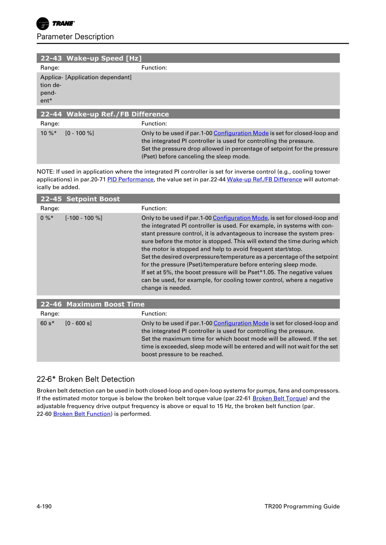
Beyond network communication, the TR200 VFD boasts robust internal protective features. It continuously monitors both the motor and the drive for thermal overload, displaying the percentage of thermal load and issuing warnings or alarms if limits are exceeded. Additionally, the drive provides current monitoring and limiting capabilities, restricting the maximum current supplied to the motor to manage torque output effectively.
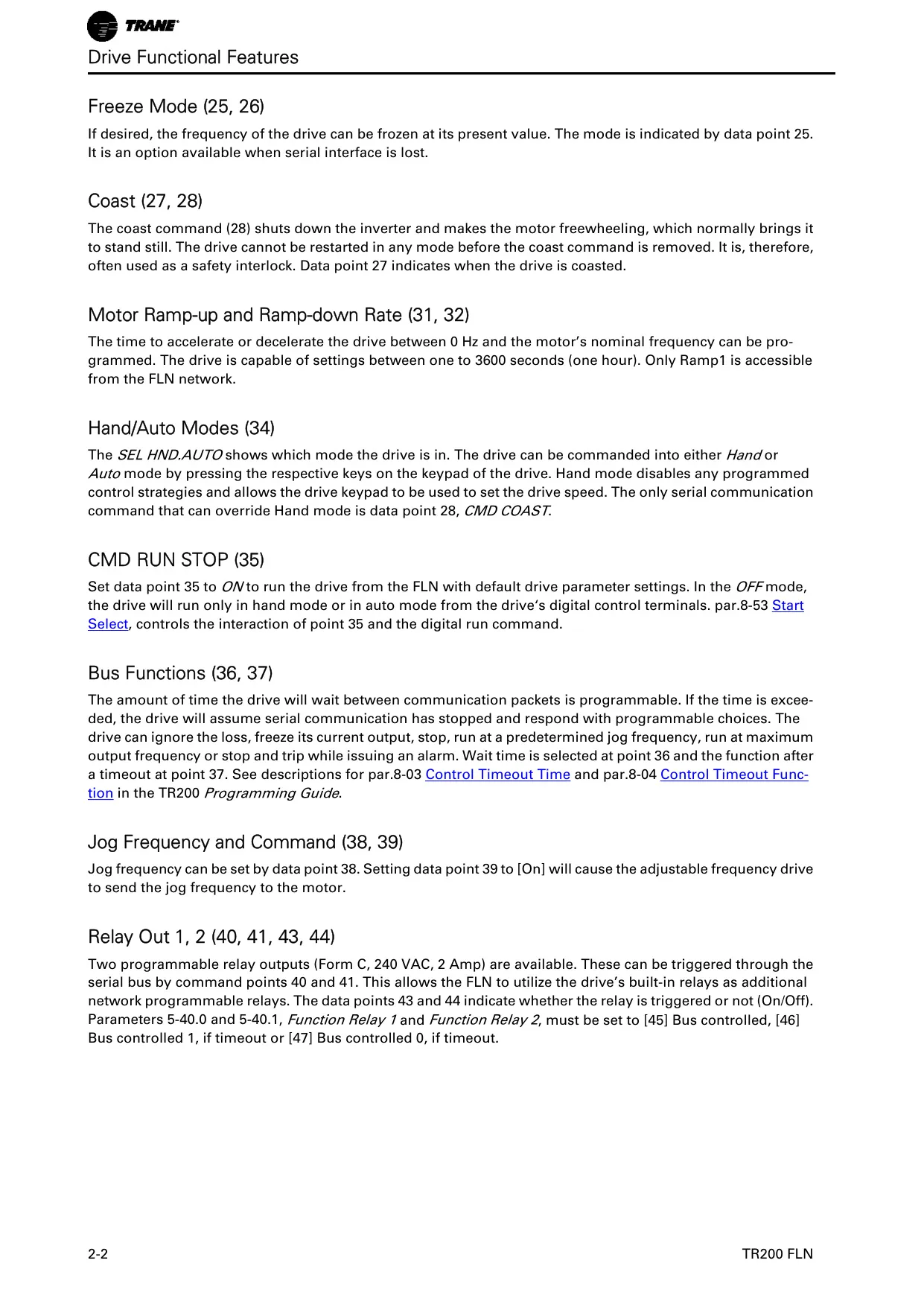
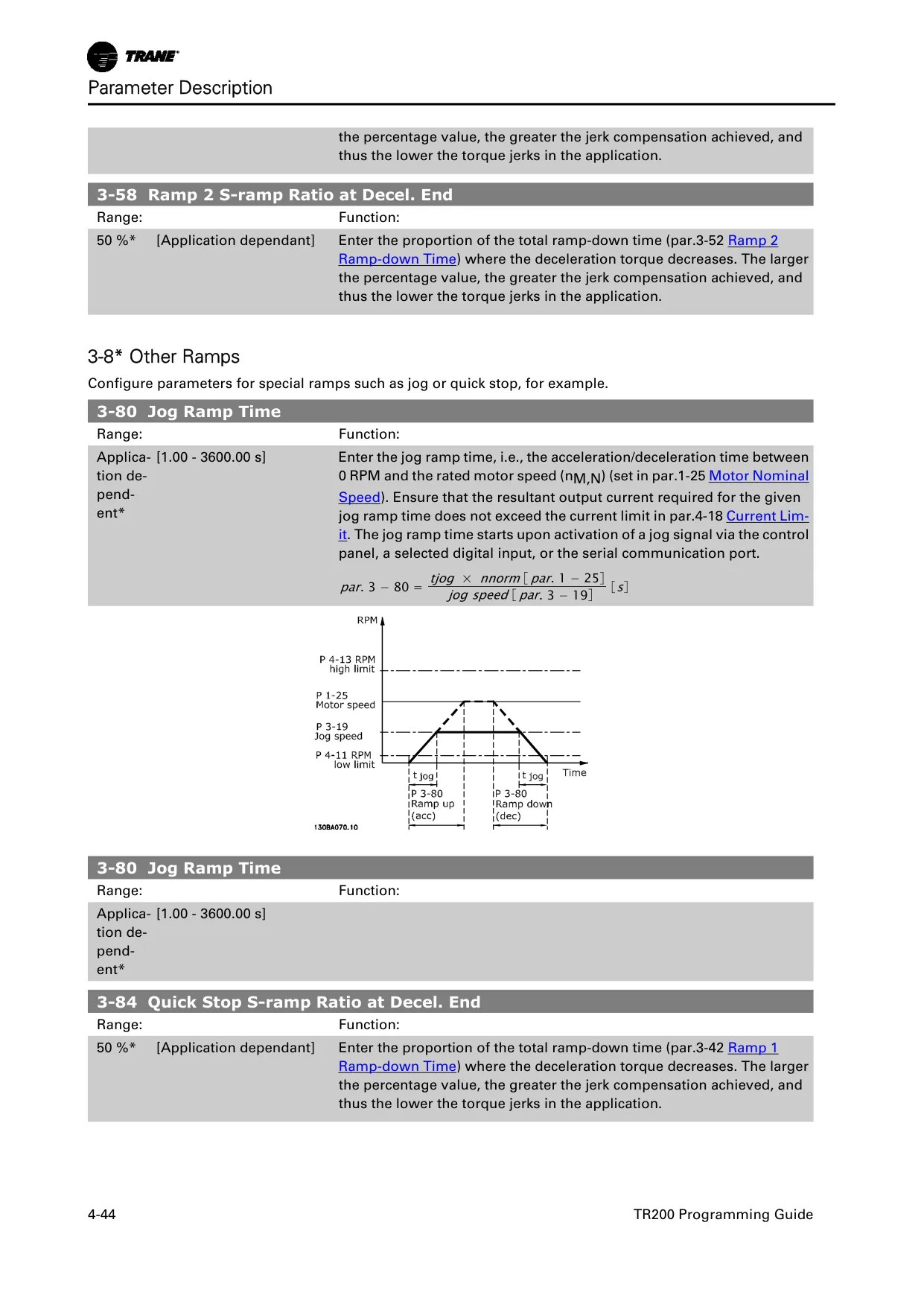
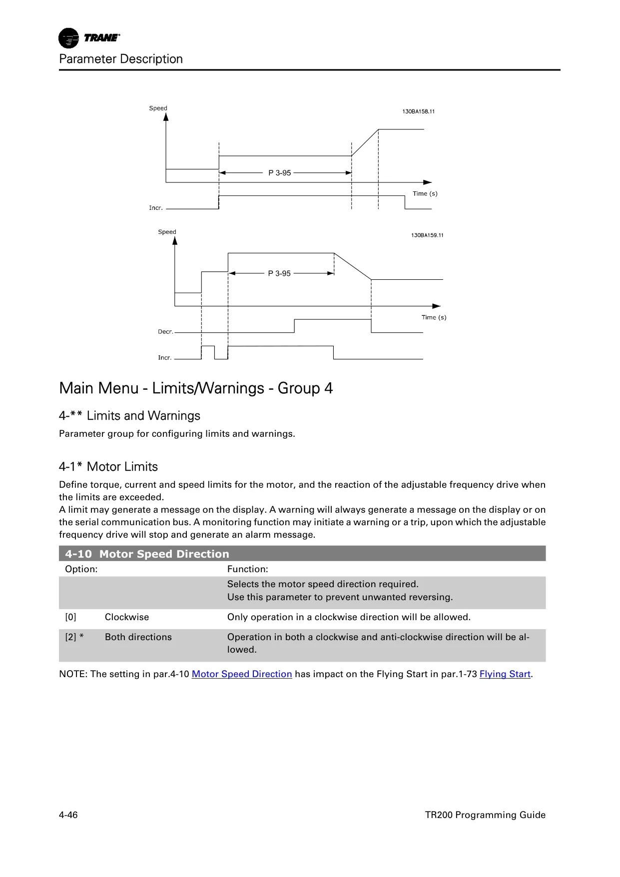
Operational flexibility is a core strength, with features like bidirectional motor rotation, crucial for applications such as smoke extraction or de-icing cooling towers. The drive supports programmable motor ramp-up and ramp-down rates, adjustable from one to 3600 seconds. Its Hand/Auto modes offer versatile control, allowing manual speed setting via the keypad or automatic operation through digital inputs or FLN commands.
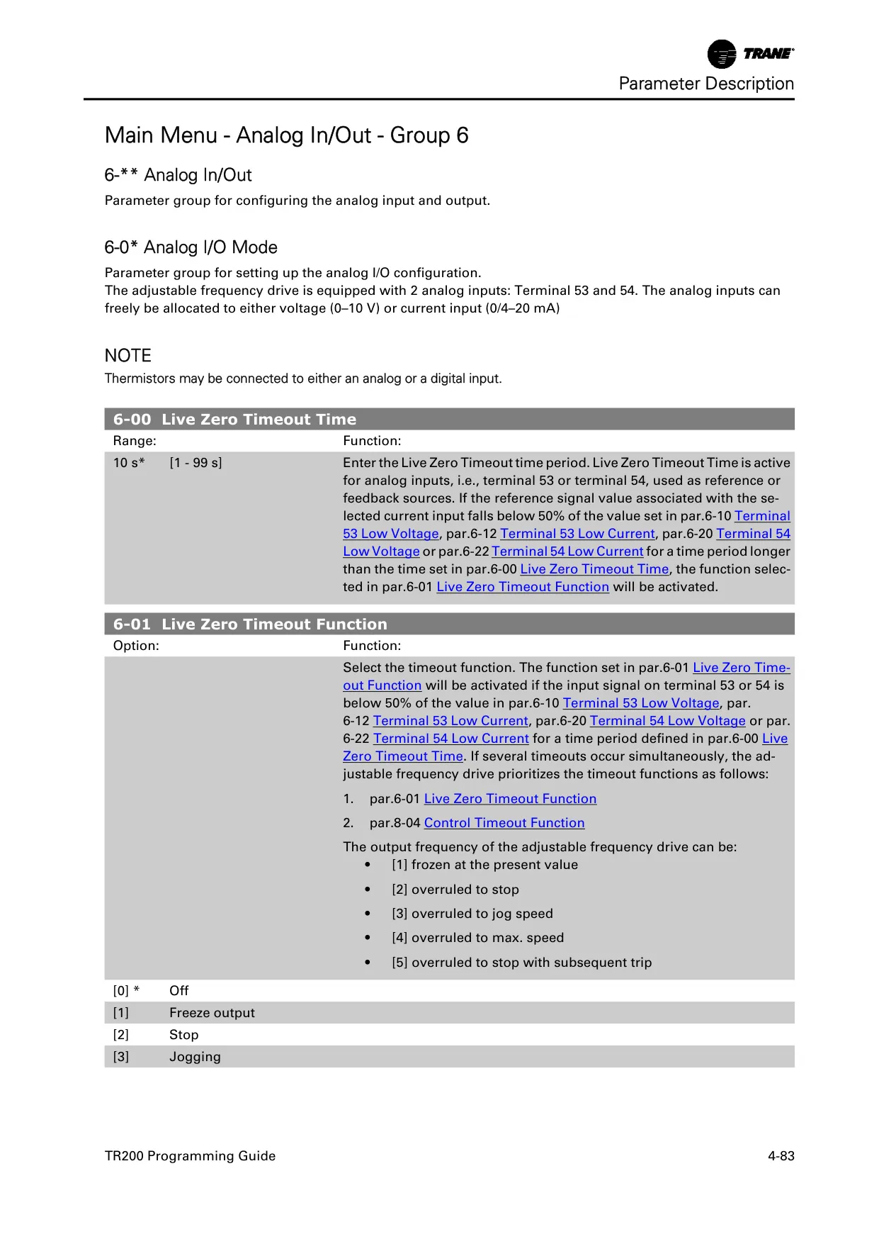
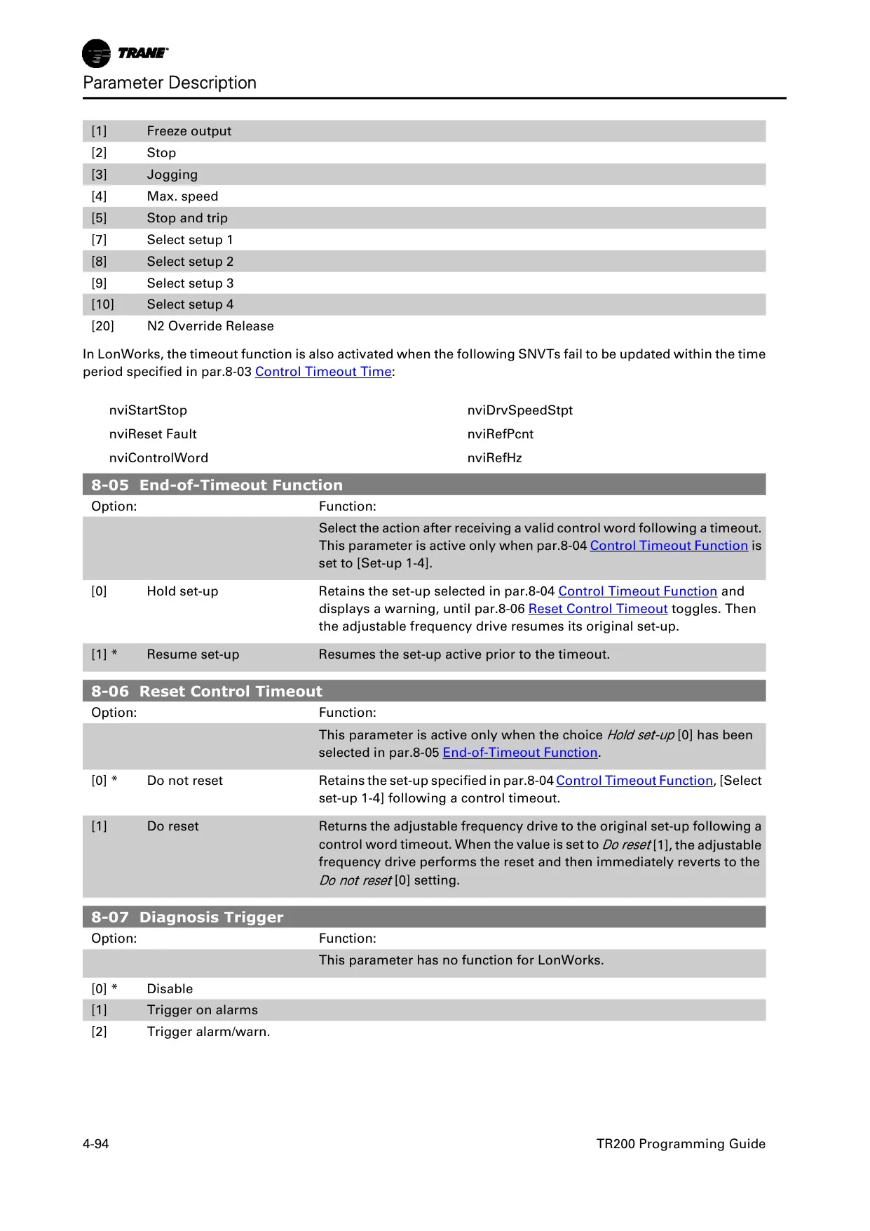
To ensure network reliability, the TR200 VFD includes configurable bus functions. Users can program the drive to respond to communication timeouts by ignoring the loss, freezing its current output, stopping, or running at a preset jog frequency. This level of customization ensures consistent operation even in challenging network environments, minimizing potential disruptions to critical HVAC systems.
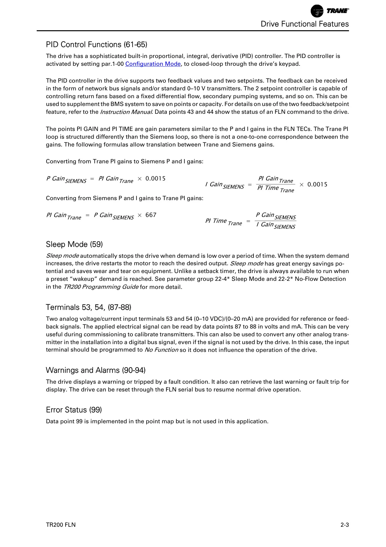
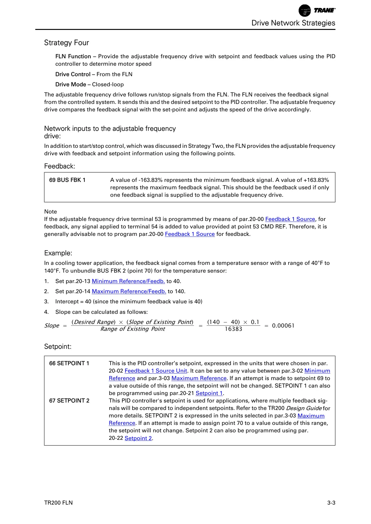
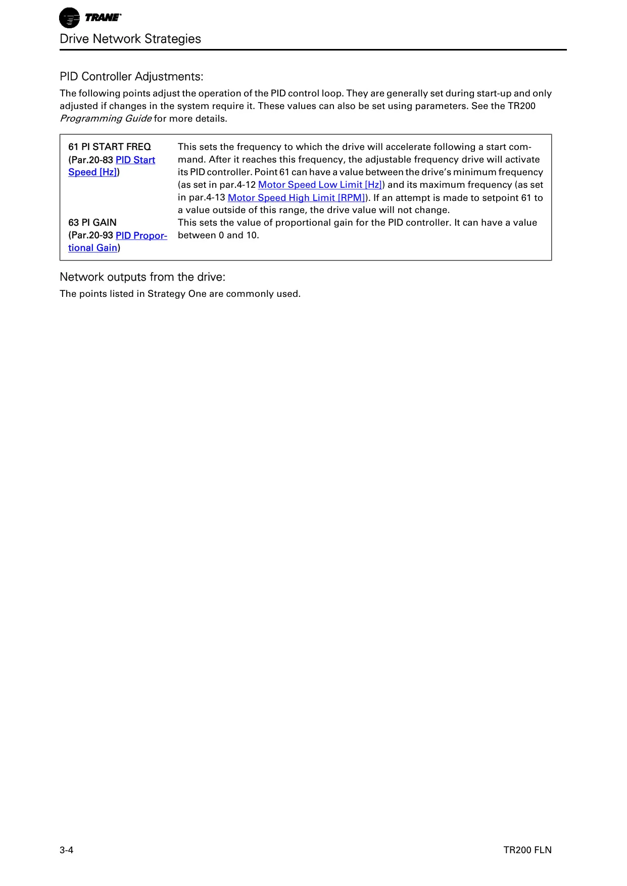
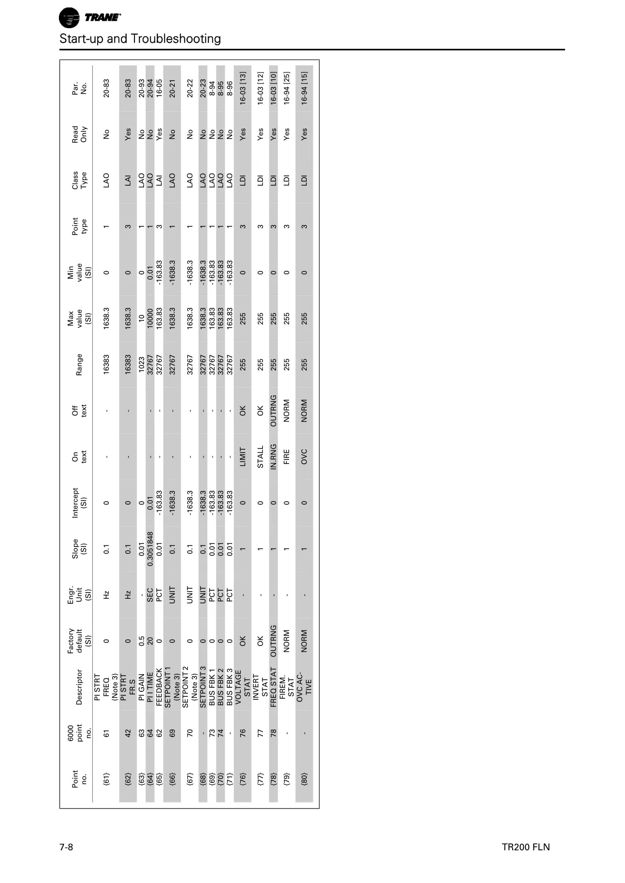
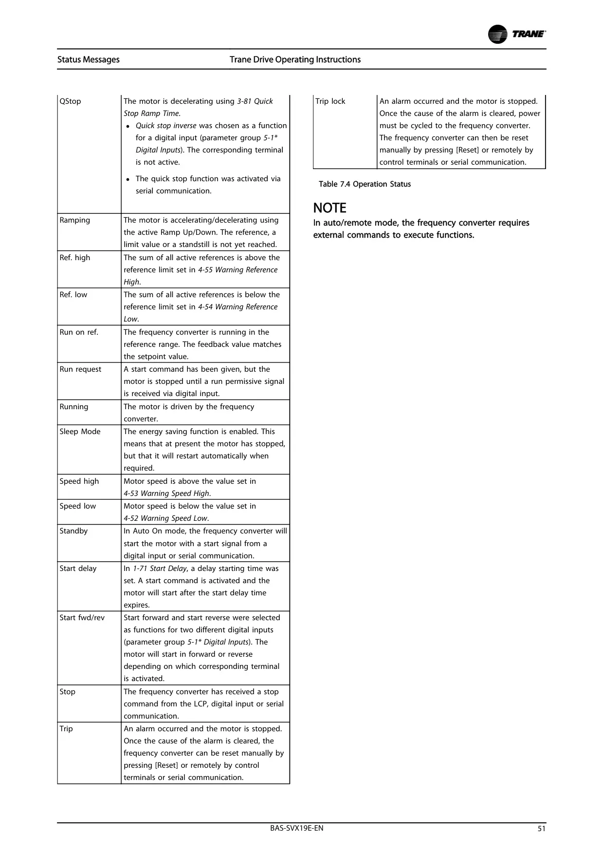
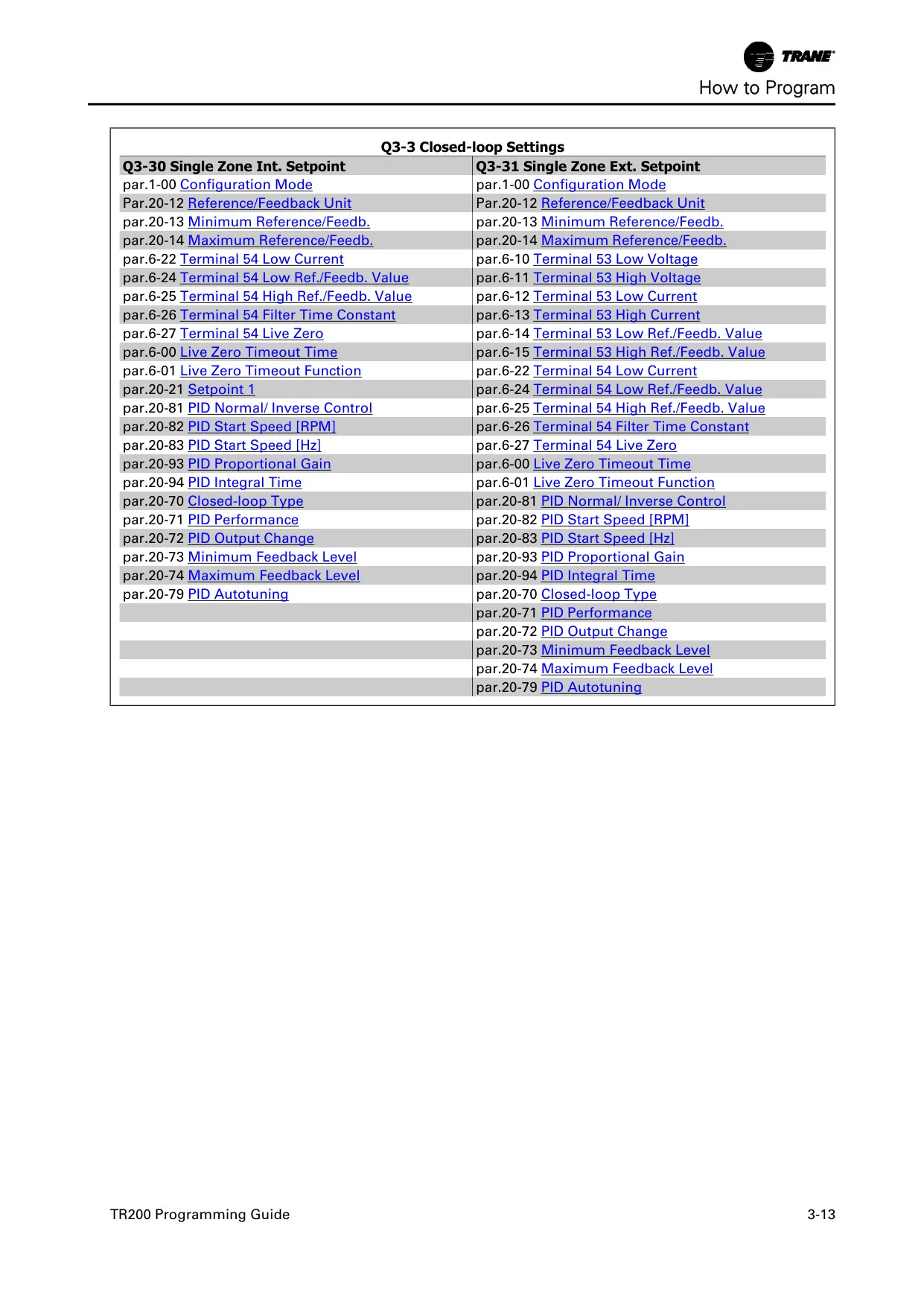
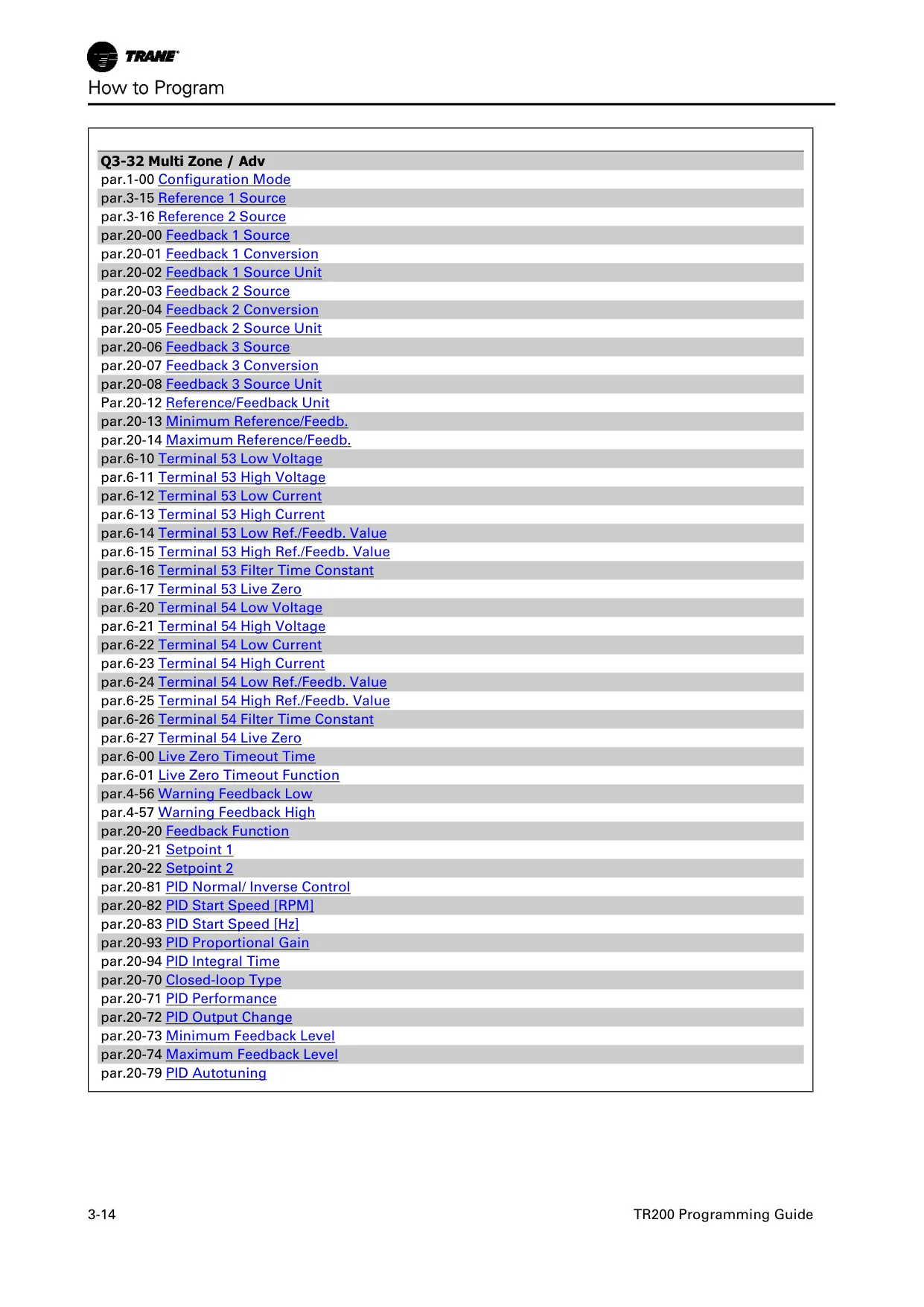
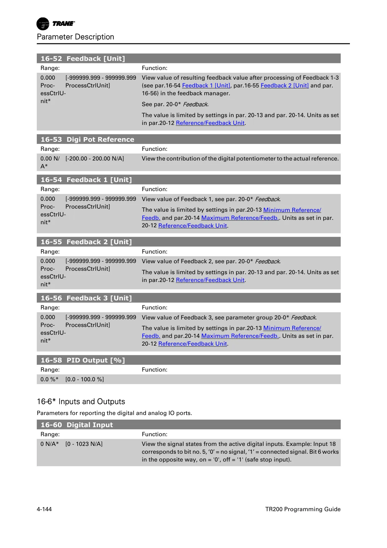
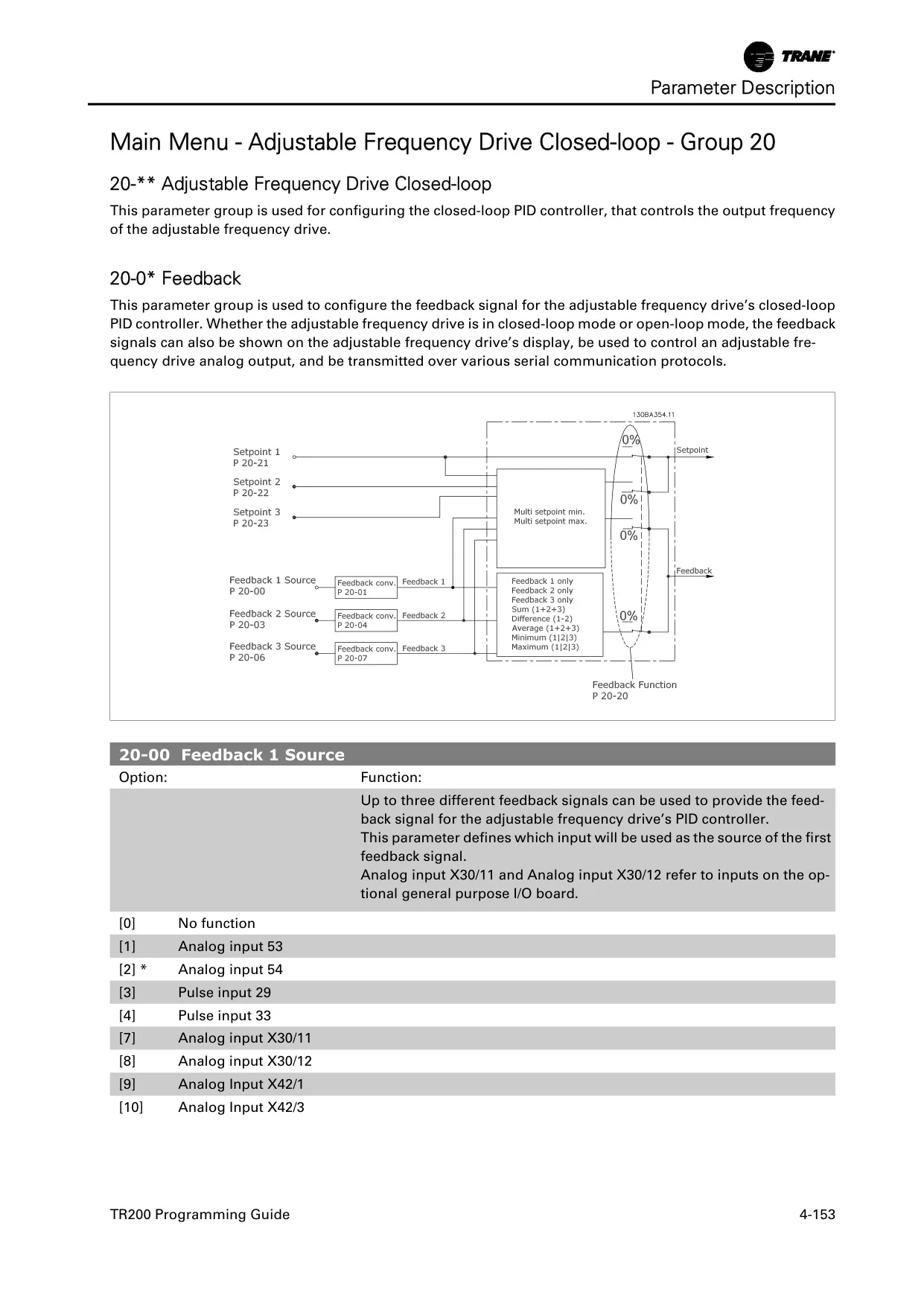
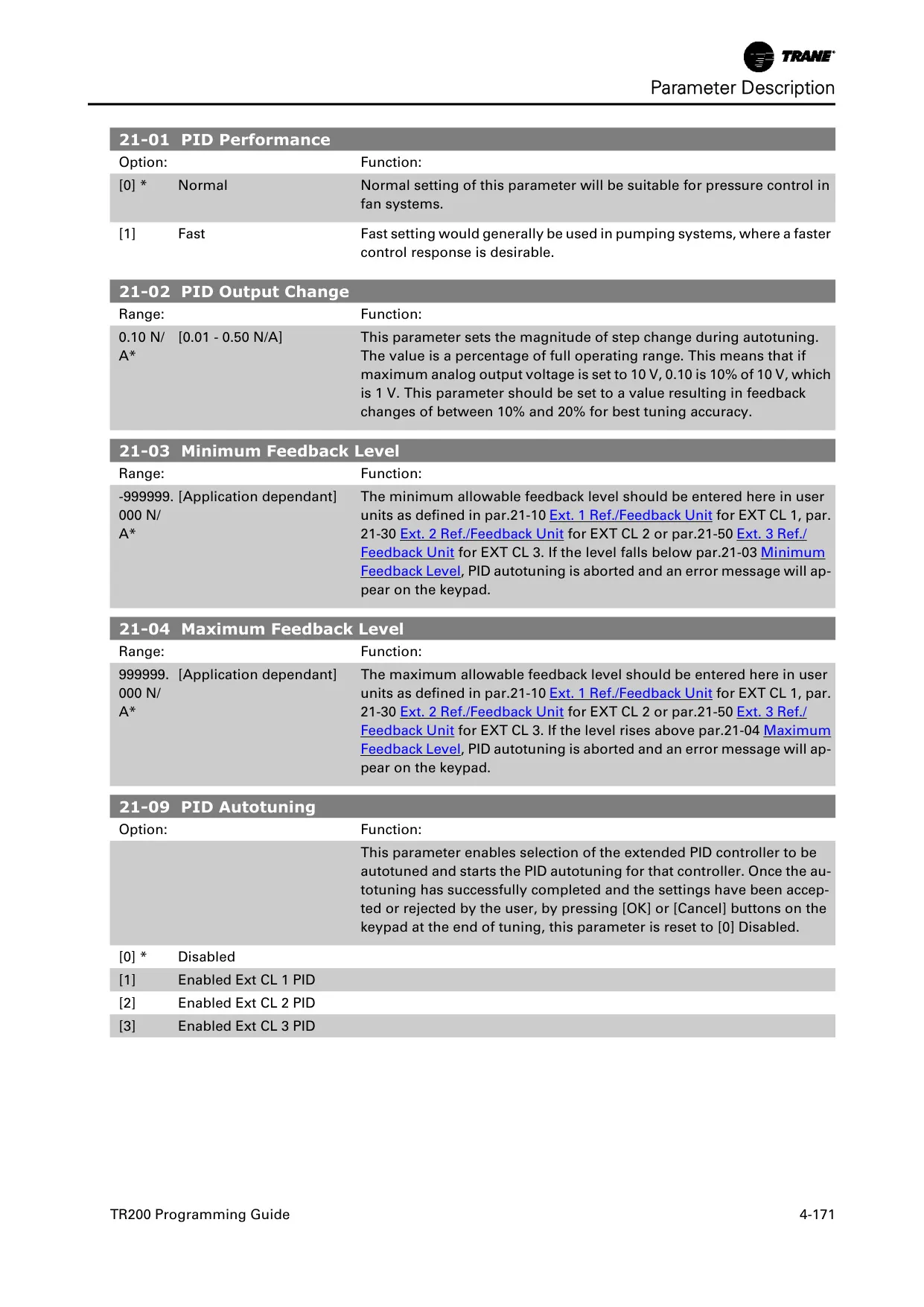
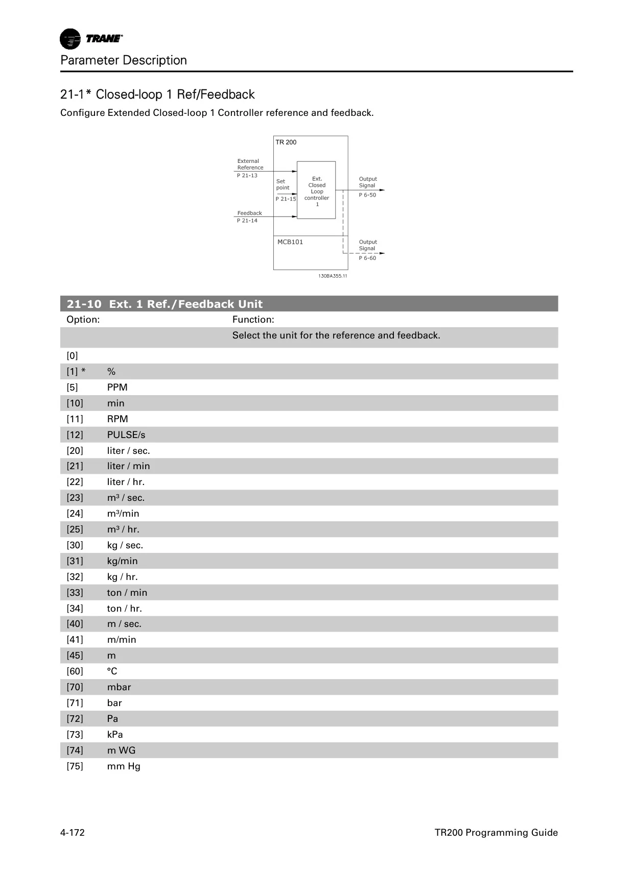
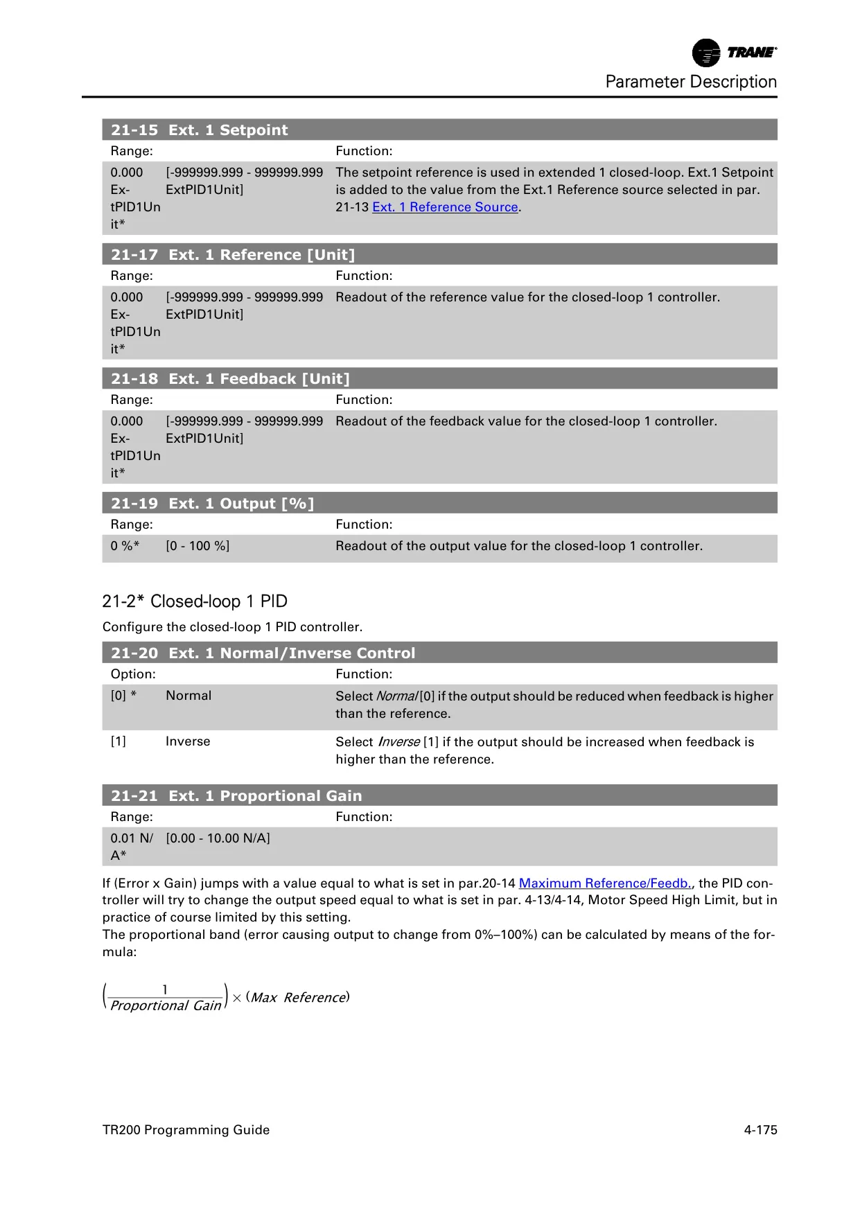
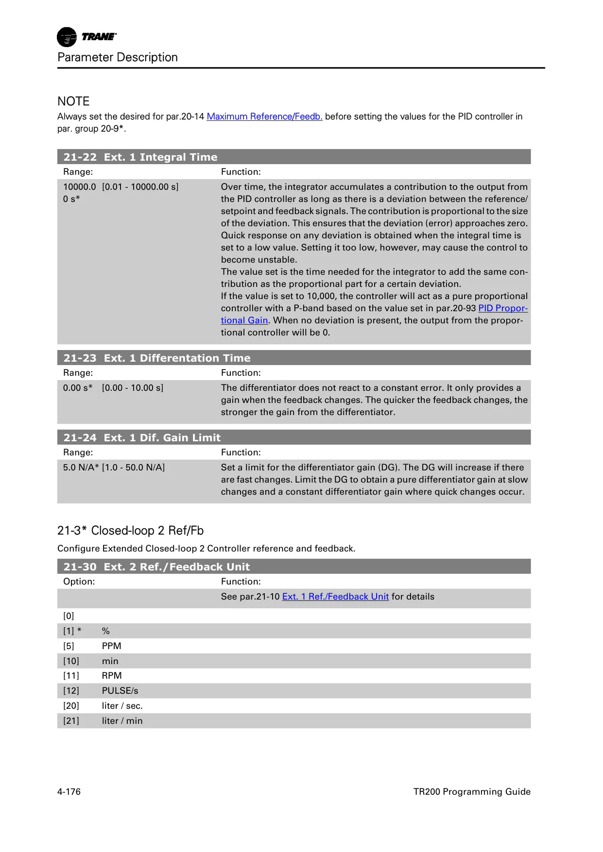
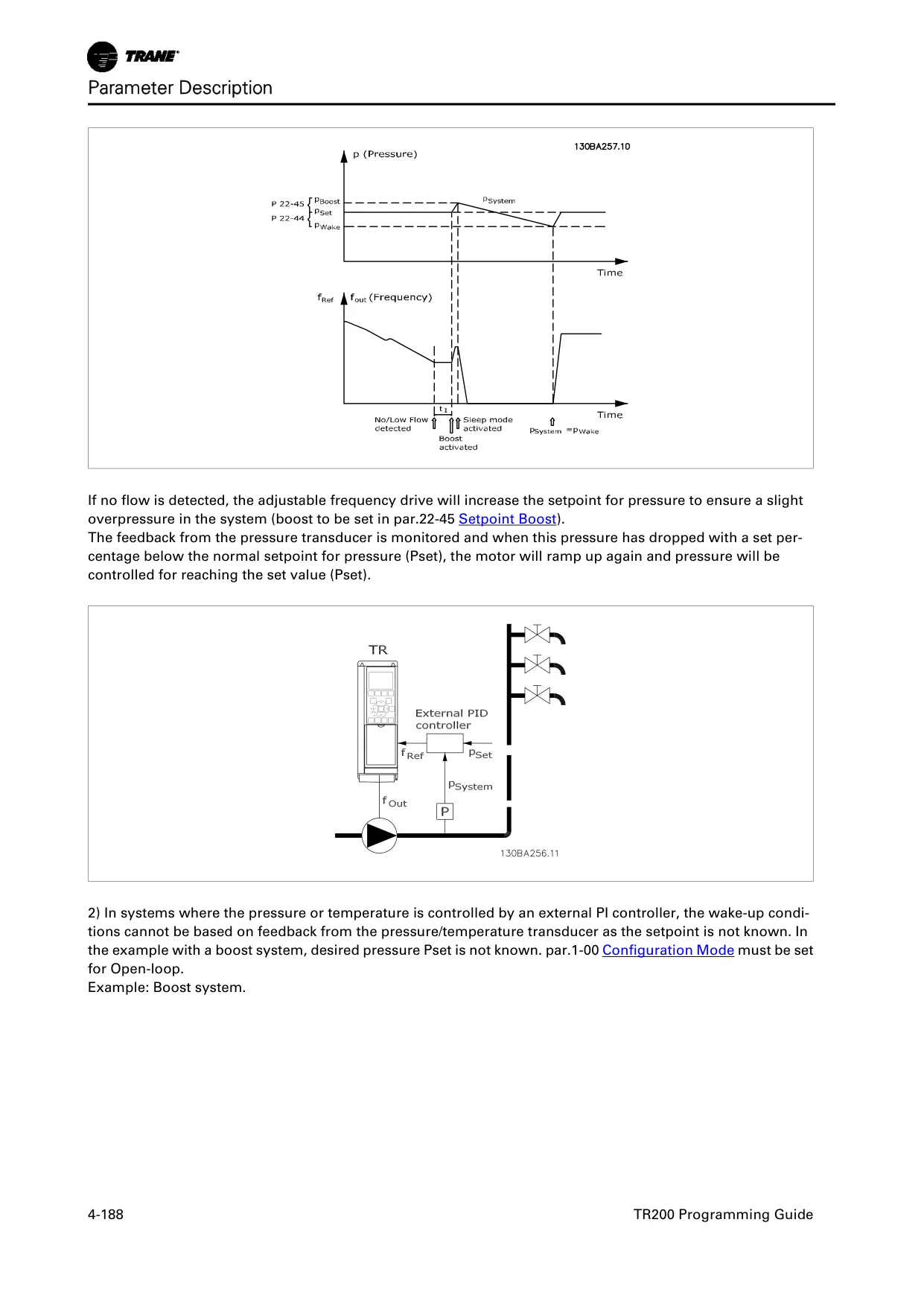
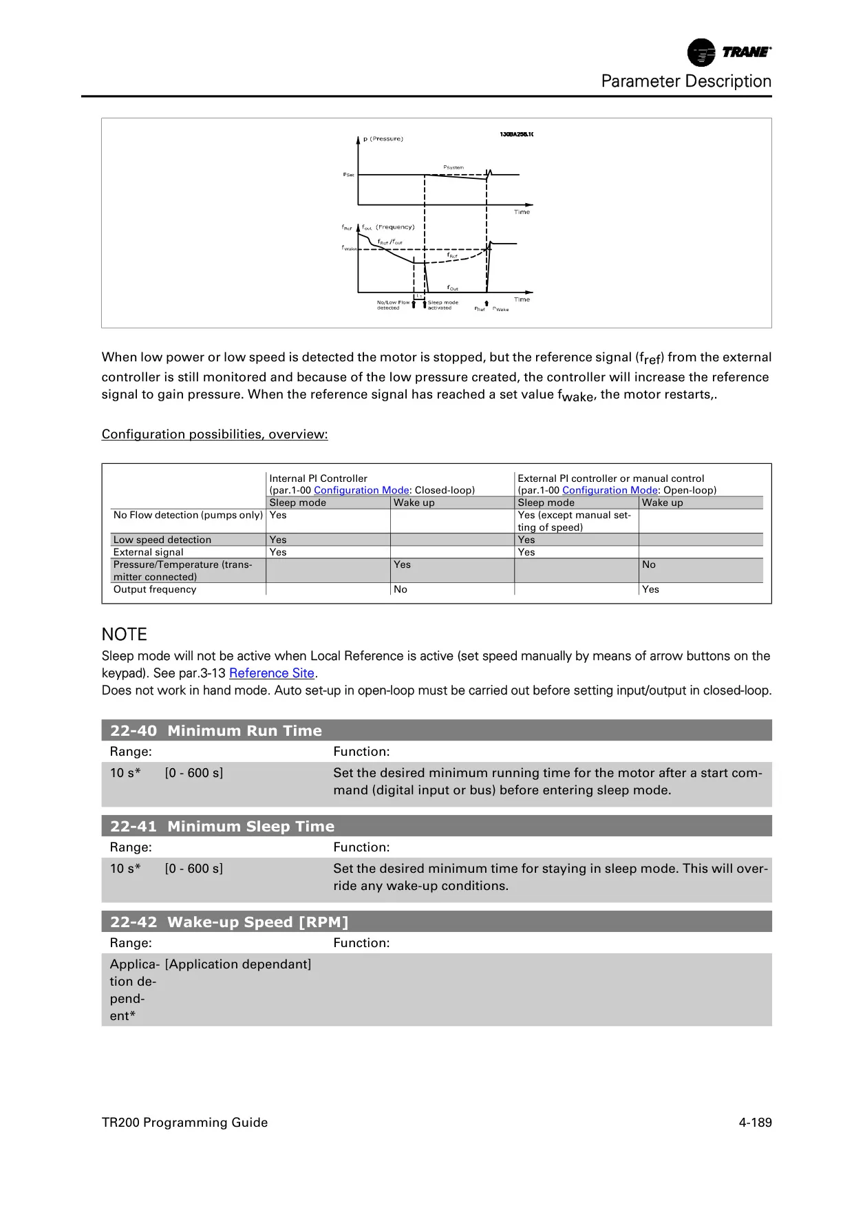
A sophisticated built-in proportional, integral, derivative (PID) controller is a standout feature, enabling closed-loop system control directly from the drive. This PID controller supports two feedback values and two setpoints, adaptable for various applications like controlling return fans or secondary pumping systems. Furthermore, the TR200 includes a practical Sleep Mode for energy savings, automatically stopping the drive during low demand periods and restarting when preset "wakeup" demand is met.
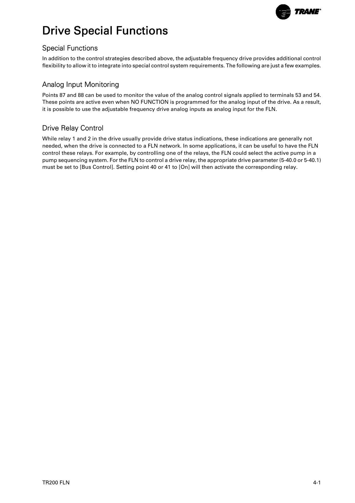
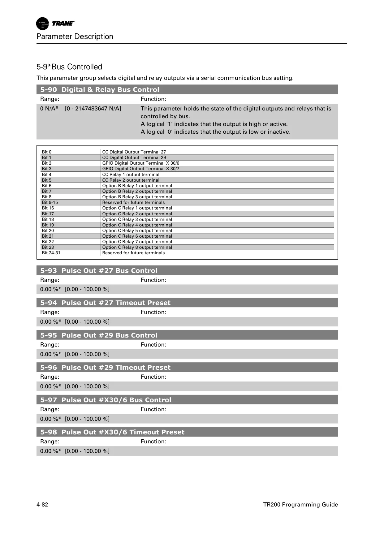
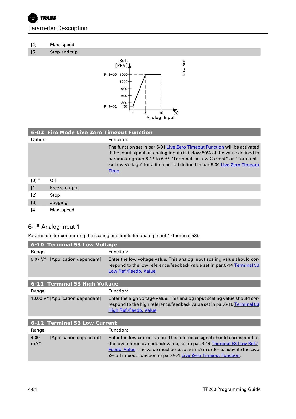
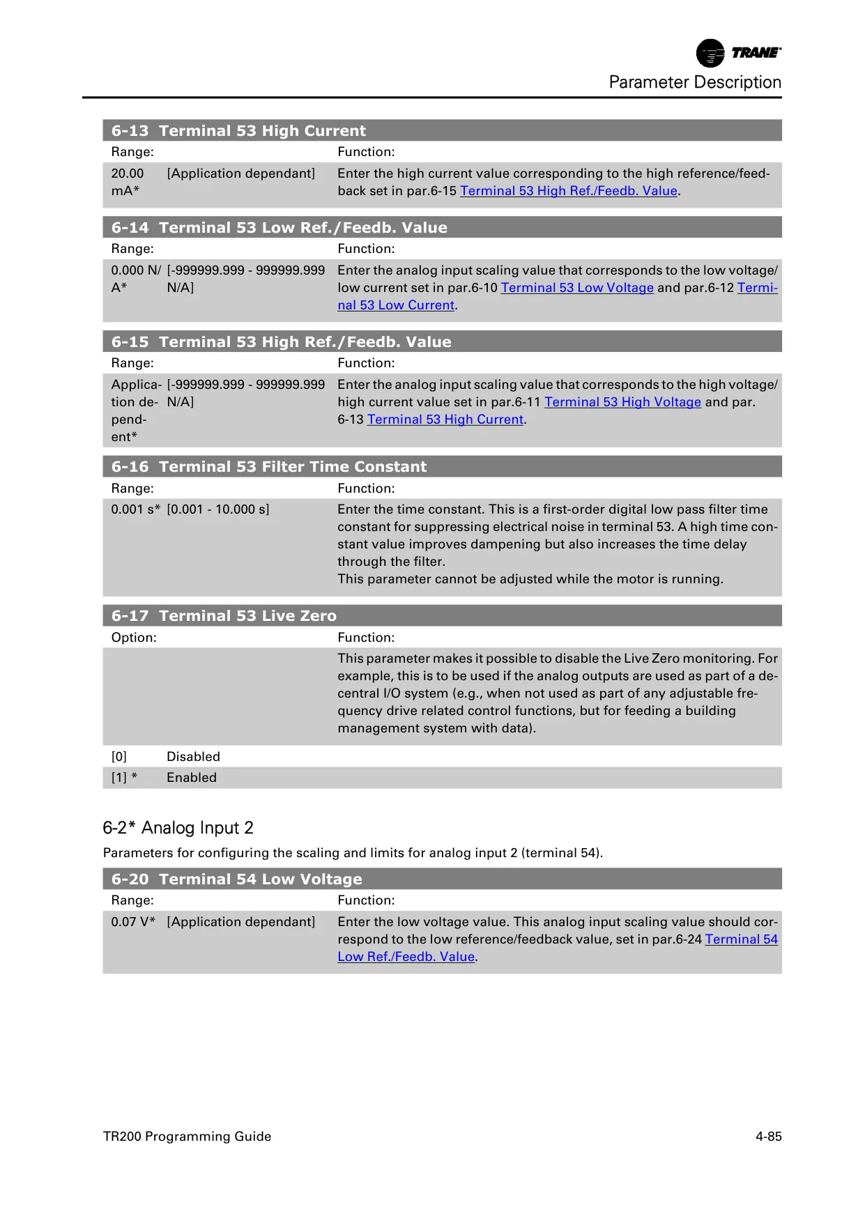
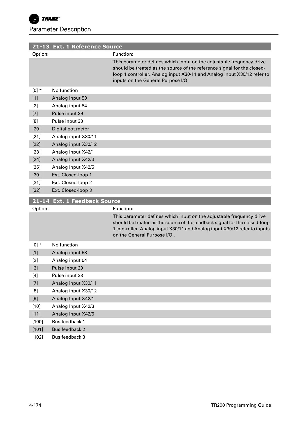
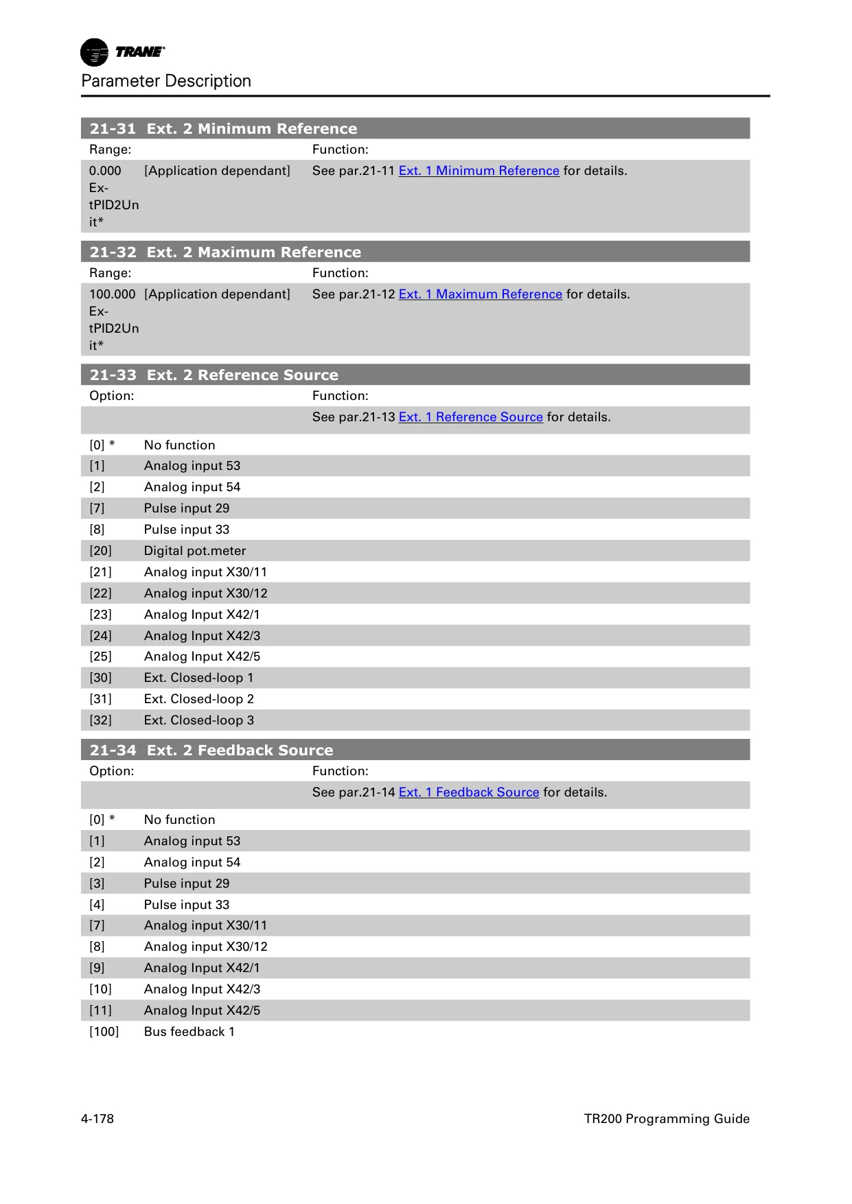
The drive’s two programmable relay outputs (Form C, 240 VAC, 2 Amp) can be controlled via the serial bus, effectively extending network programmable relay capabilities. Analog input terminals (0-10 VDC/0-20 mA) are available for reference or feedback signals, which can also be used to convert any analog transmitter signal into a digital bus signal for monitoring, aiding in commissioning and diagnostics.
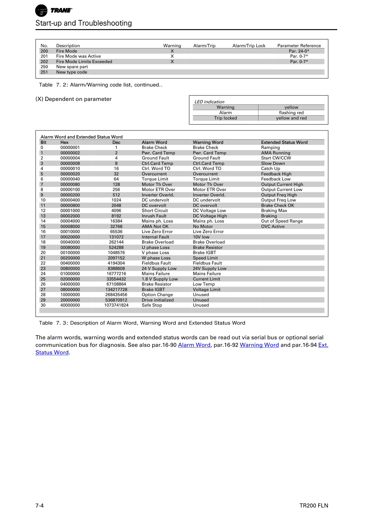
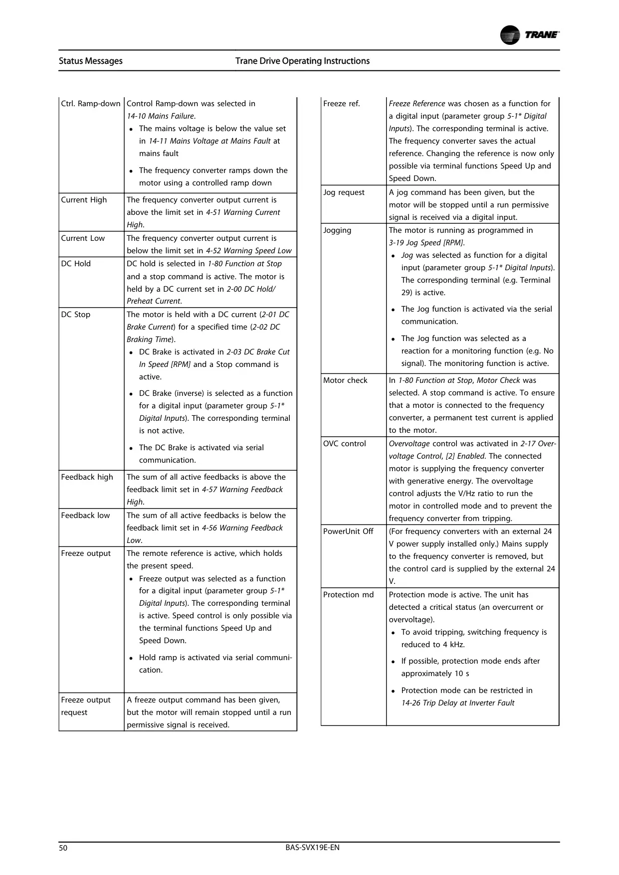
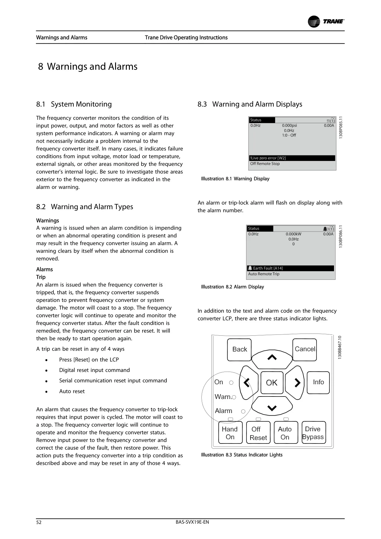
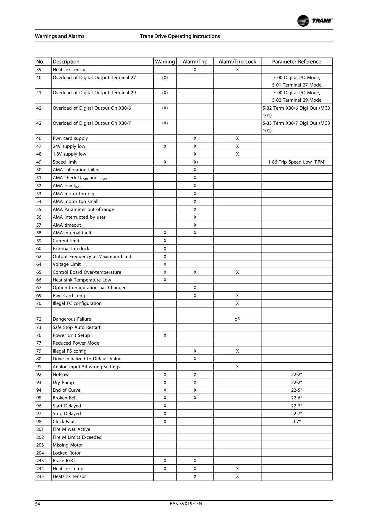
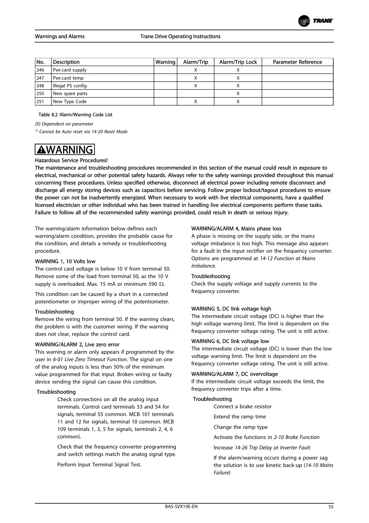
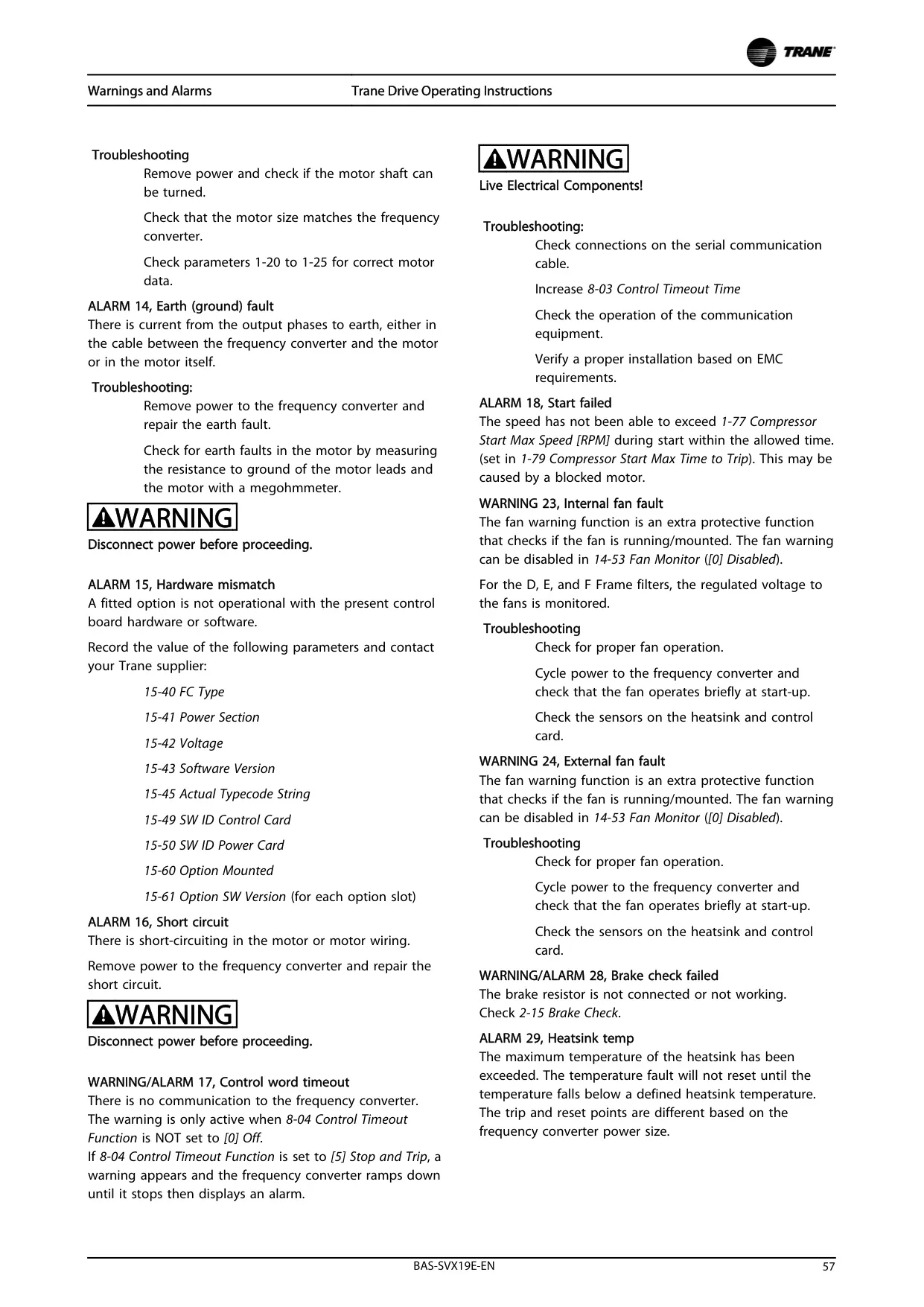
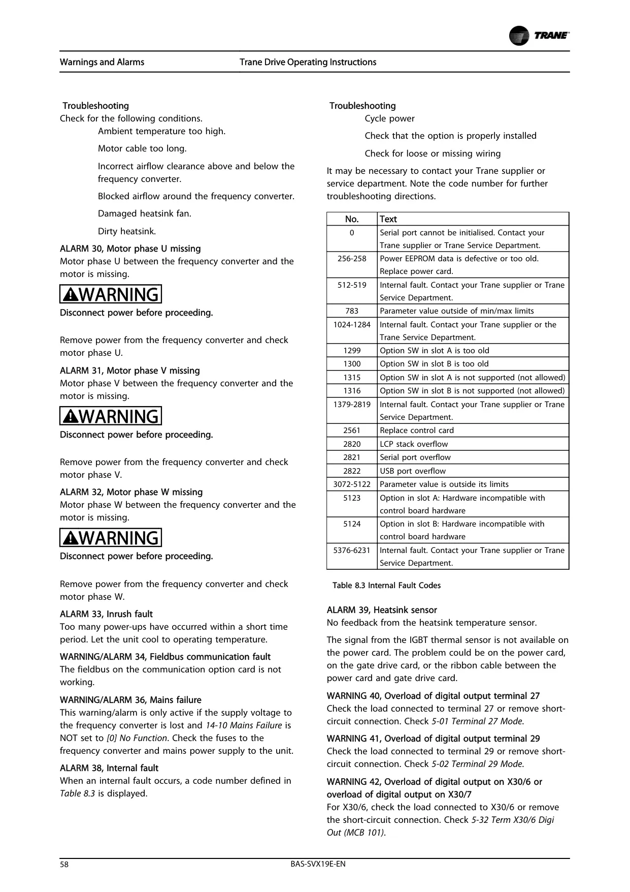
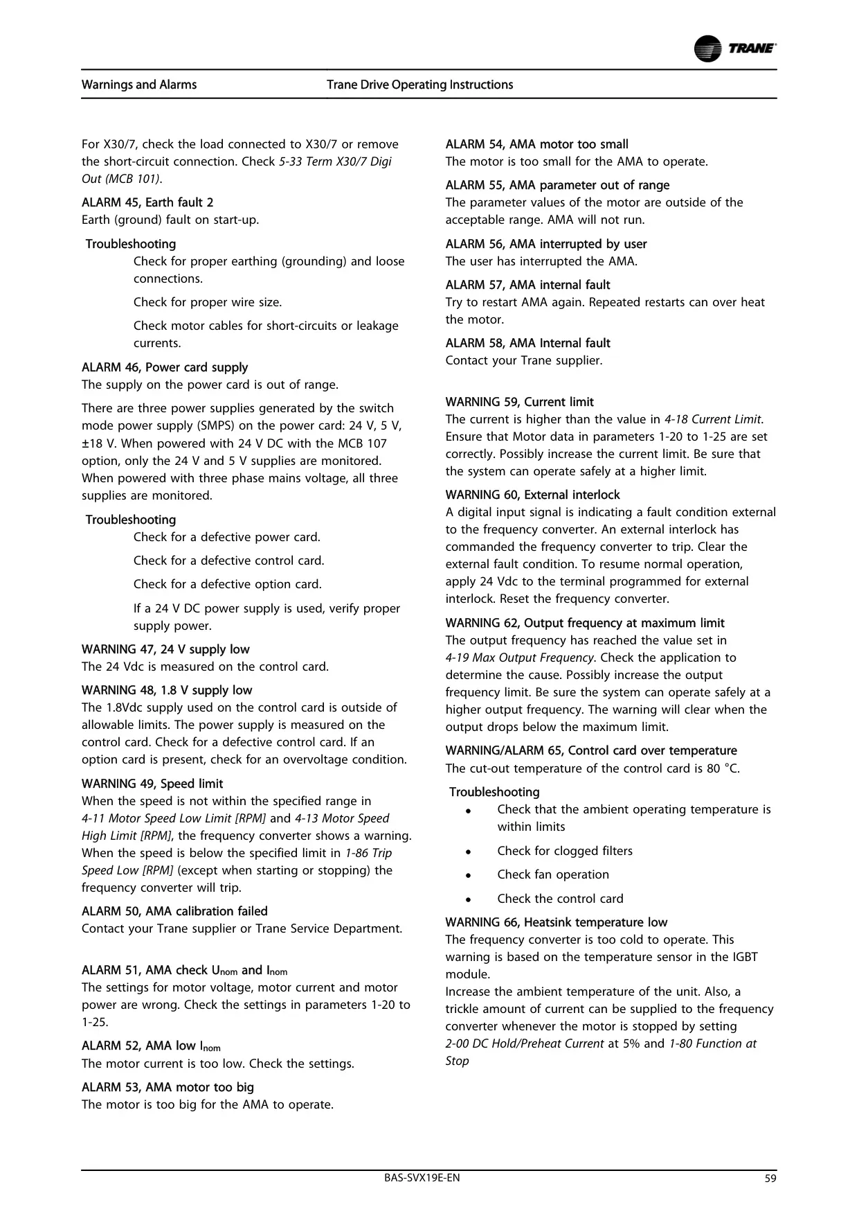
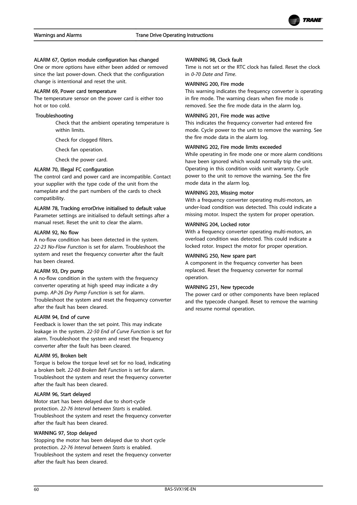
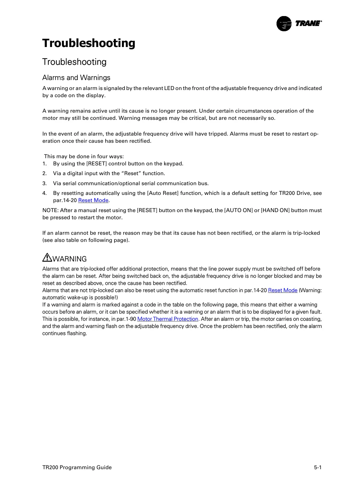
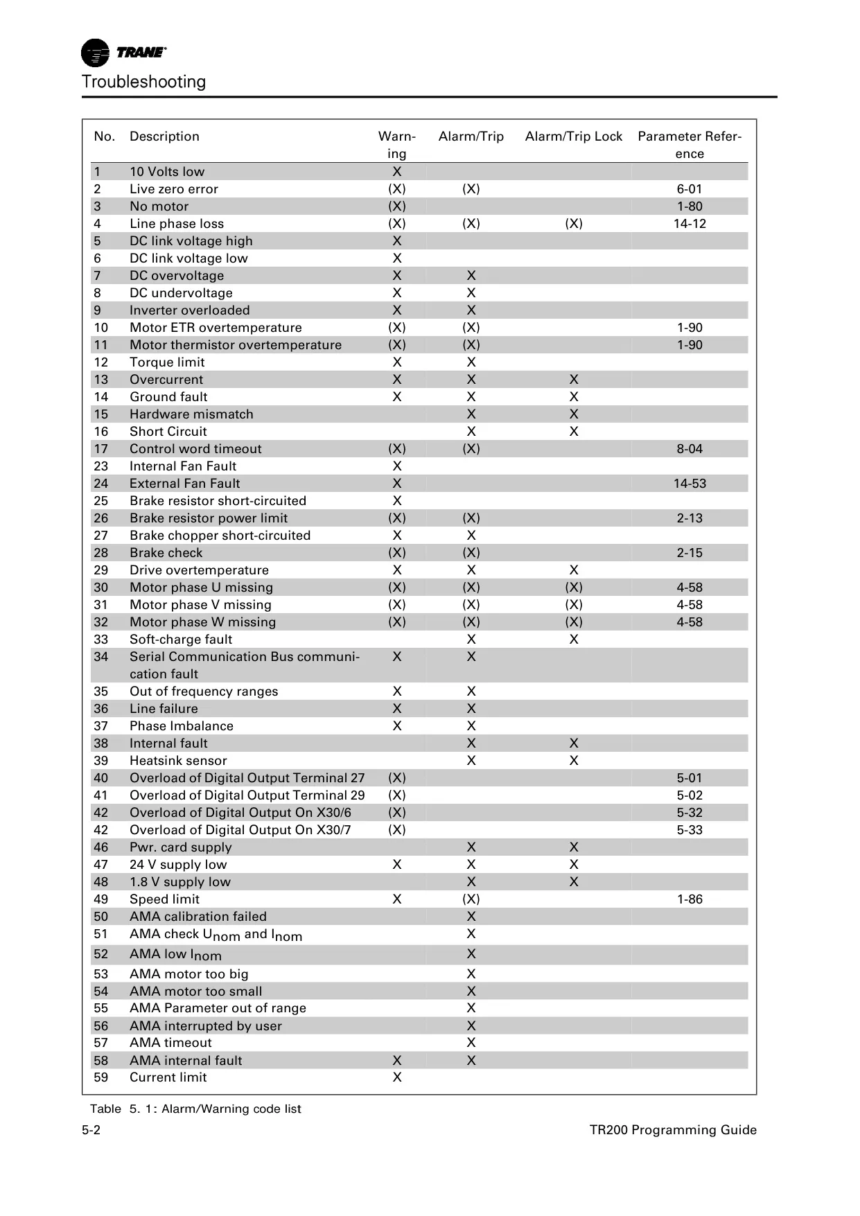
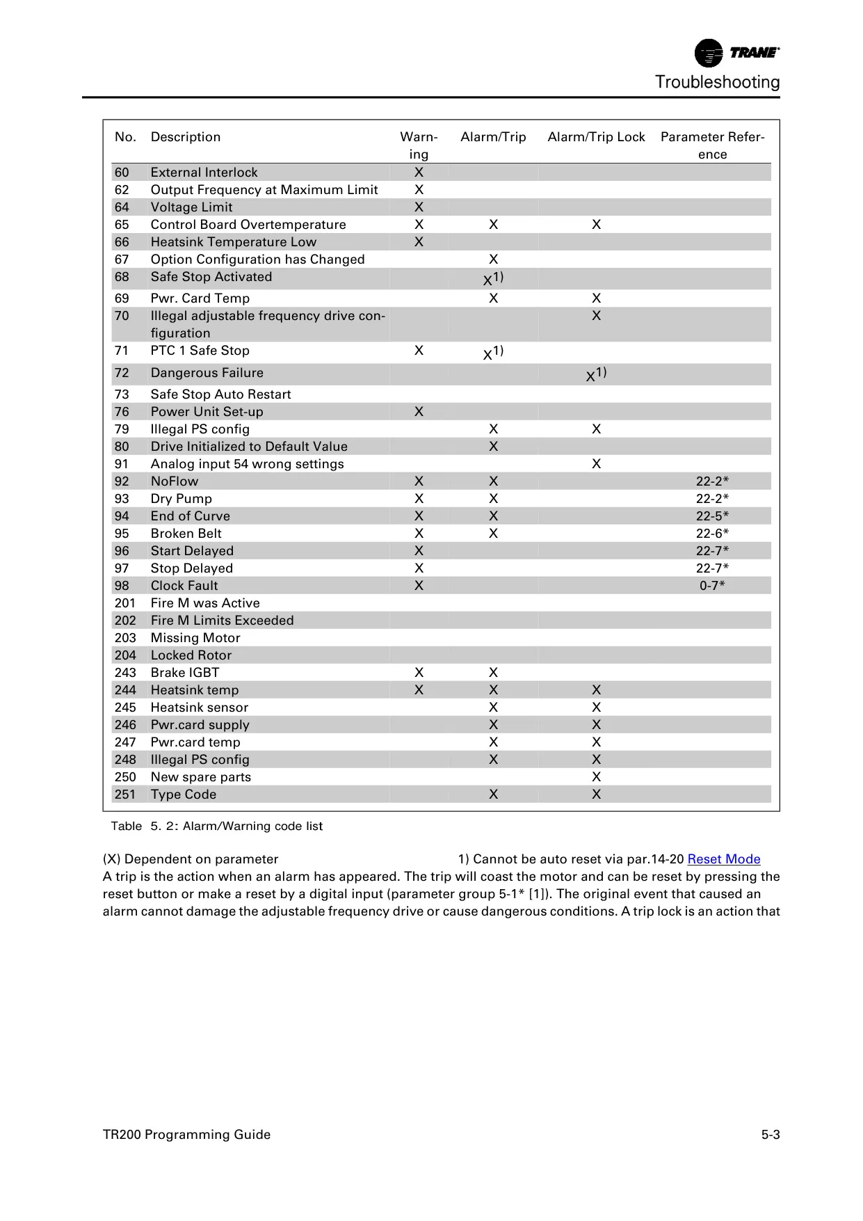
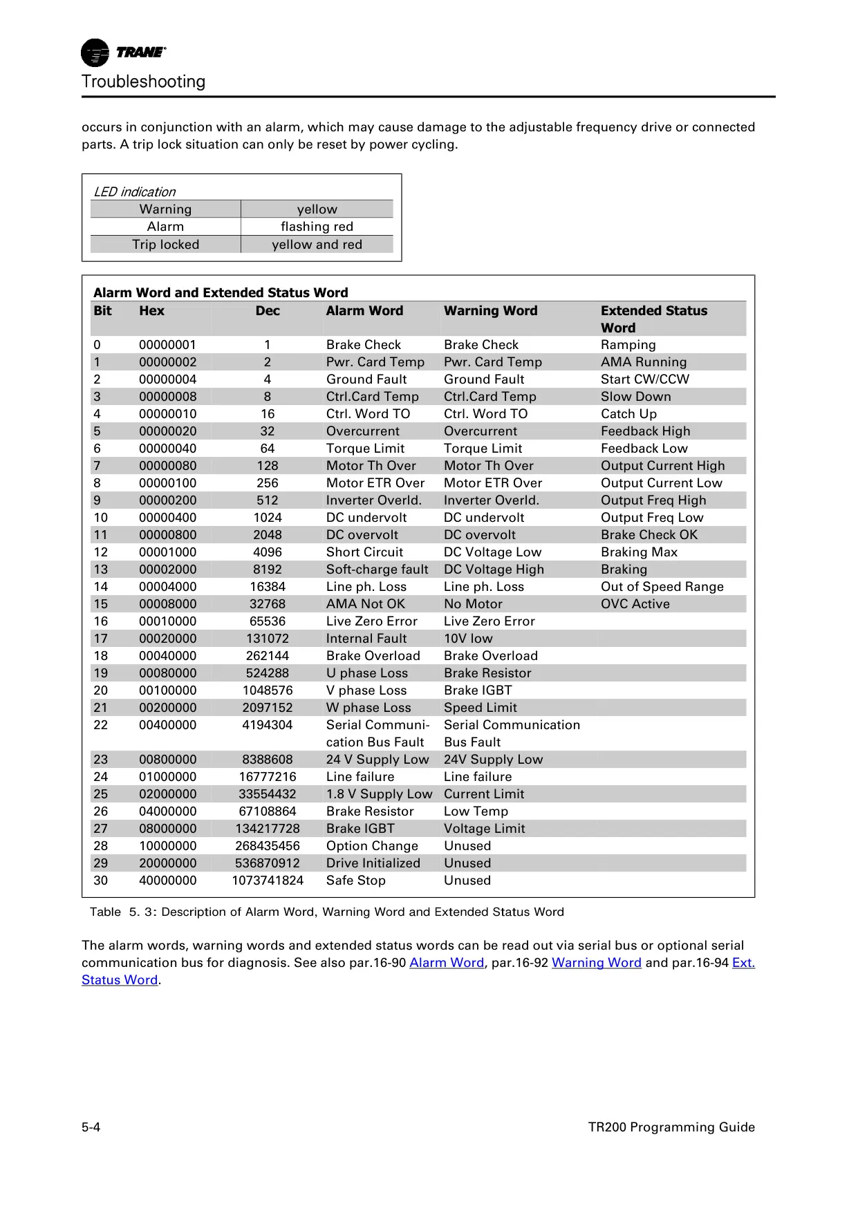
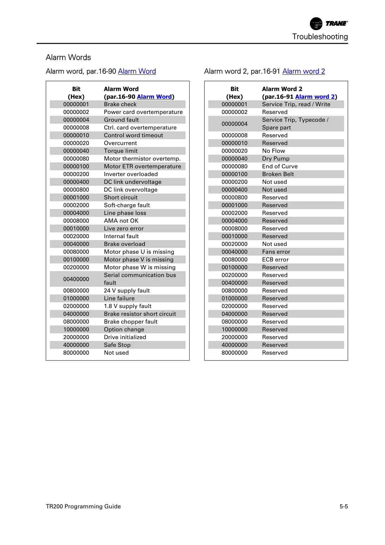
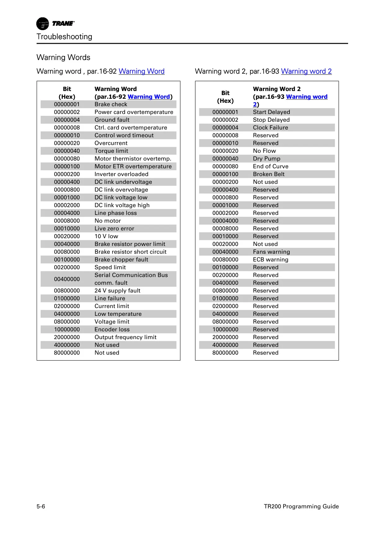
Finally, the TR200 VFD provides extensive warning and alarm systems, displaying specific codes for faults and adverse conditions. These alarms can be reset manually via the keypad, a digital input, or through the FLN serial bus, with an auto-reset function available for non-trip-locked alarms, ensuring swift recovery and continuous operation.
Frequently Asked Questions (FAQs)
Can't find the answer you need? Here are some frequently asked questions about the Trane TR200 VFD, and we answer them below.