Honeywell RM7800 Burner Control Instruction Manual
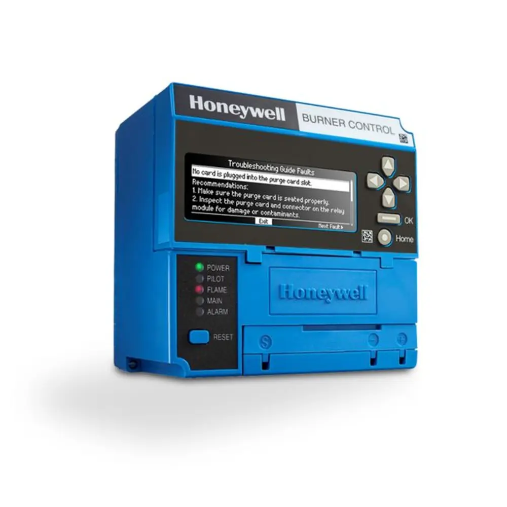
Honeywell RM7800 Burner Control
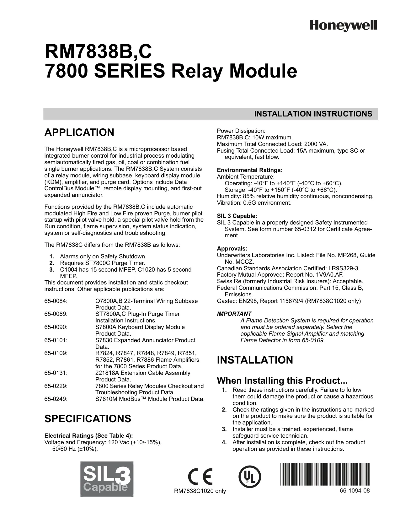
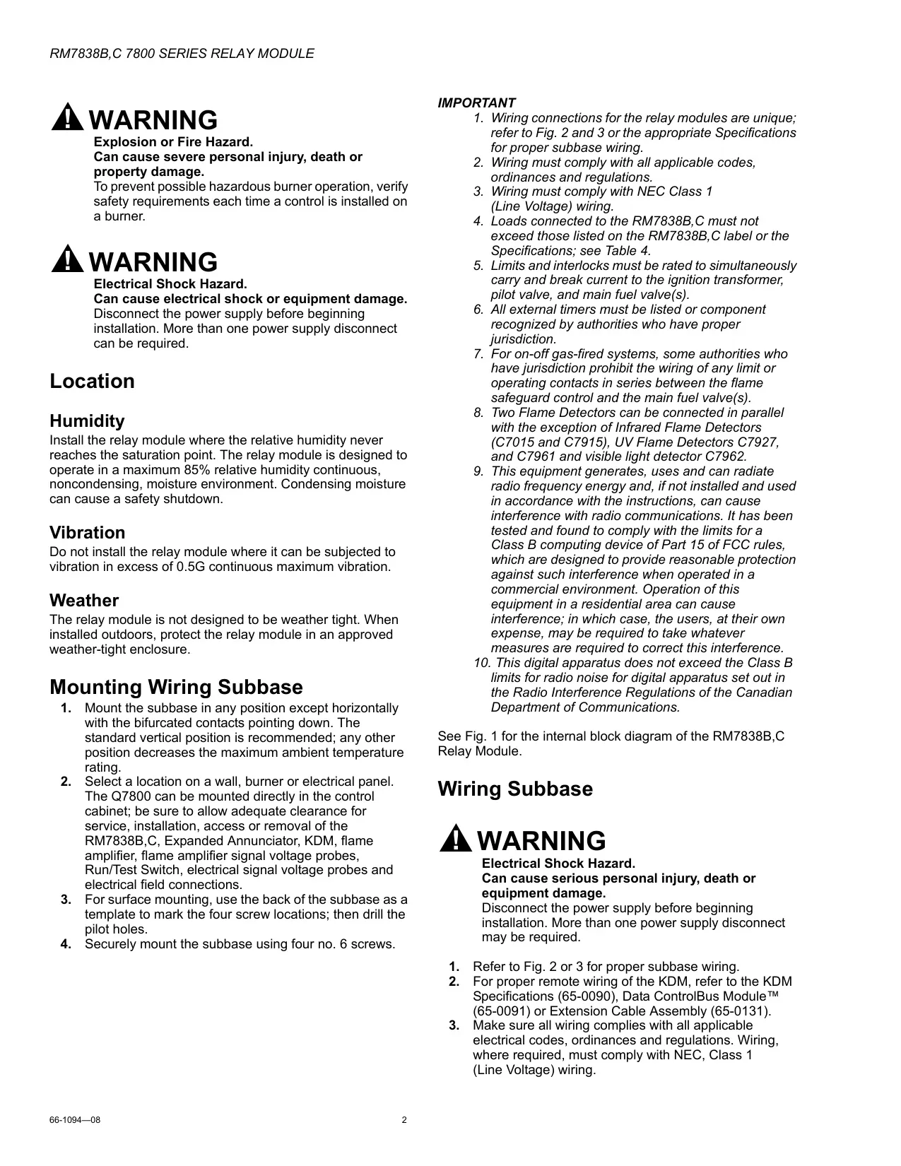
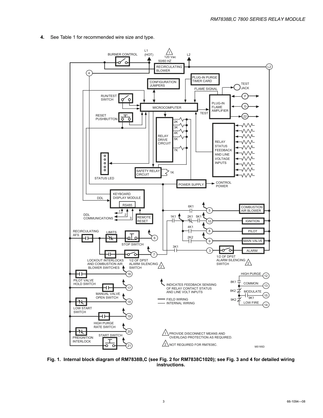
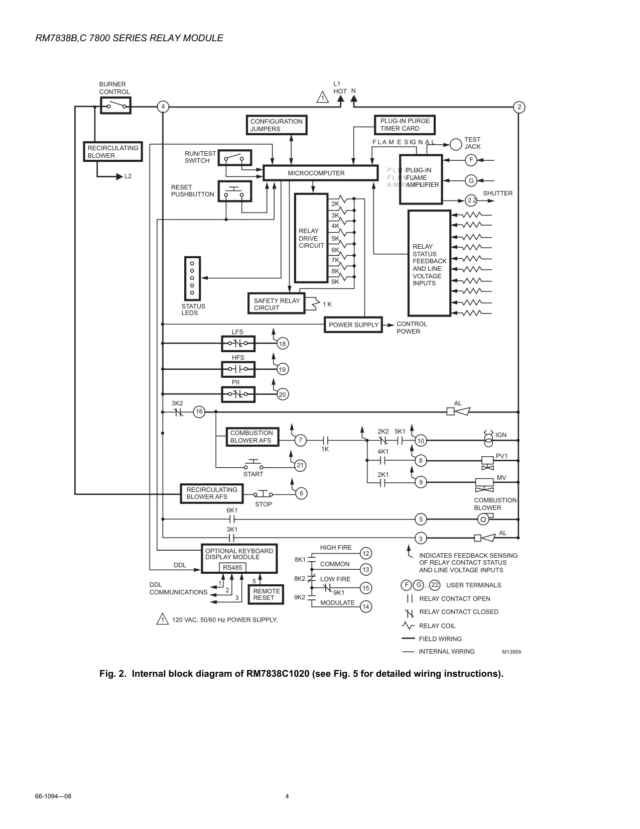
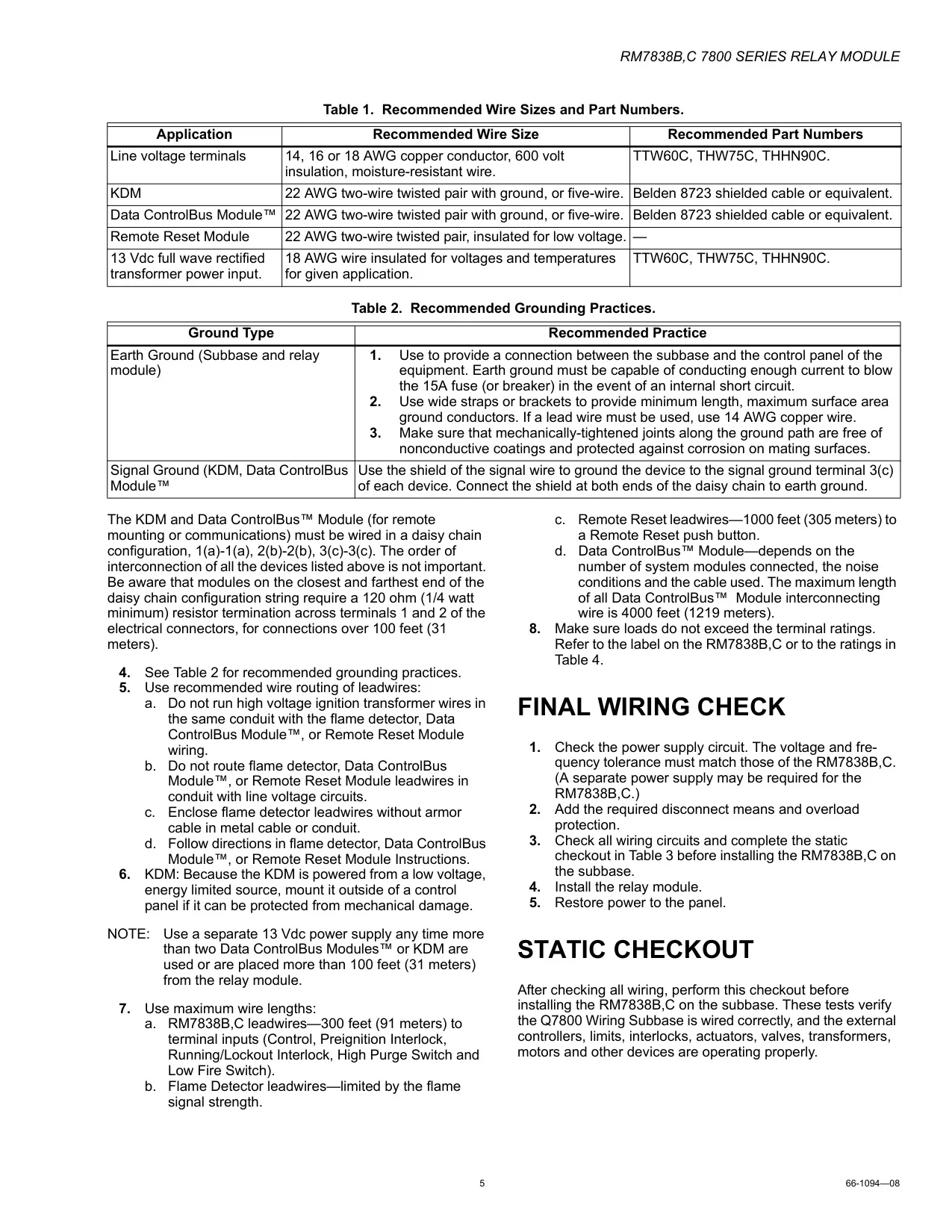
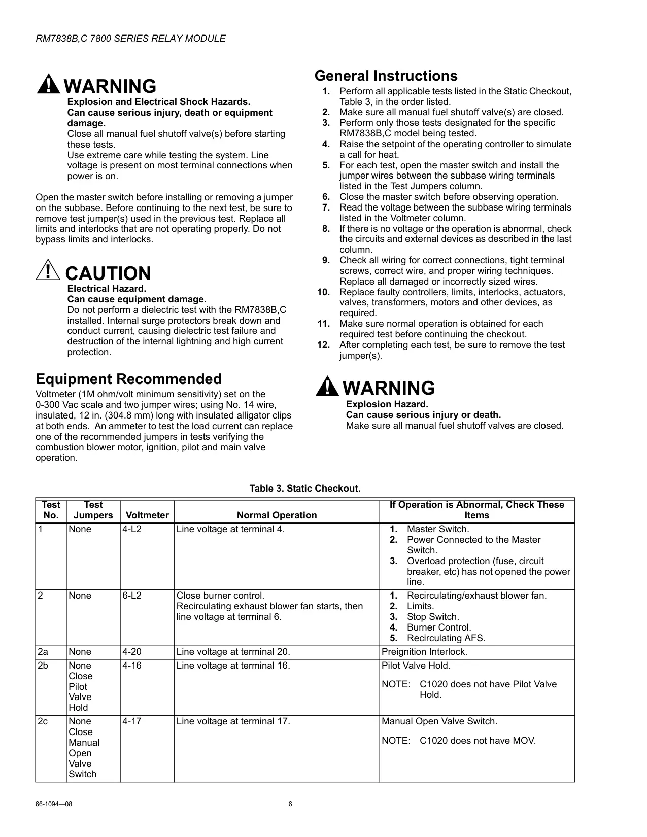
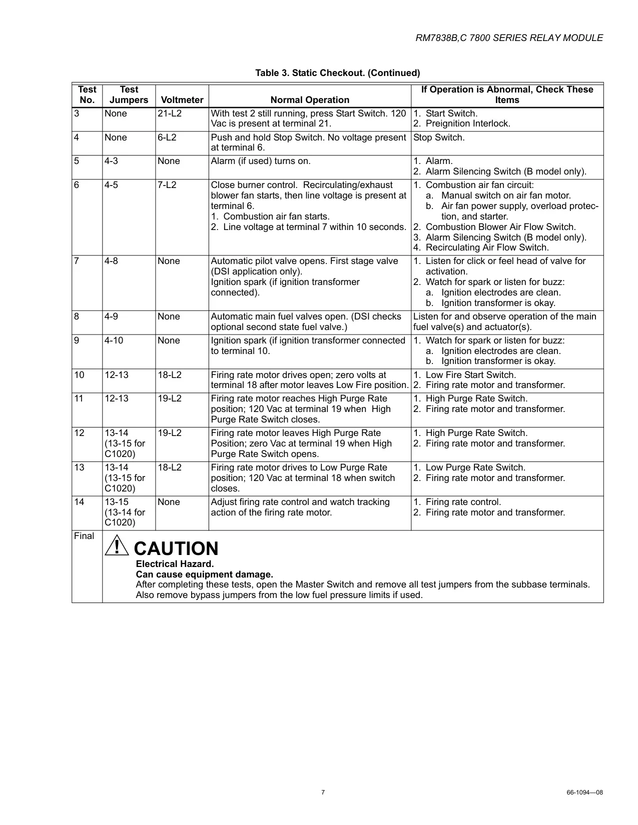
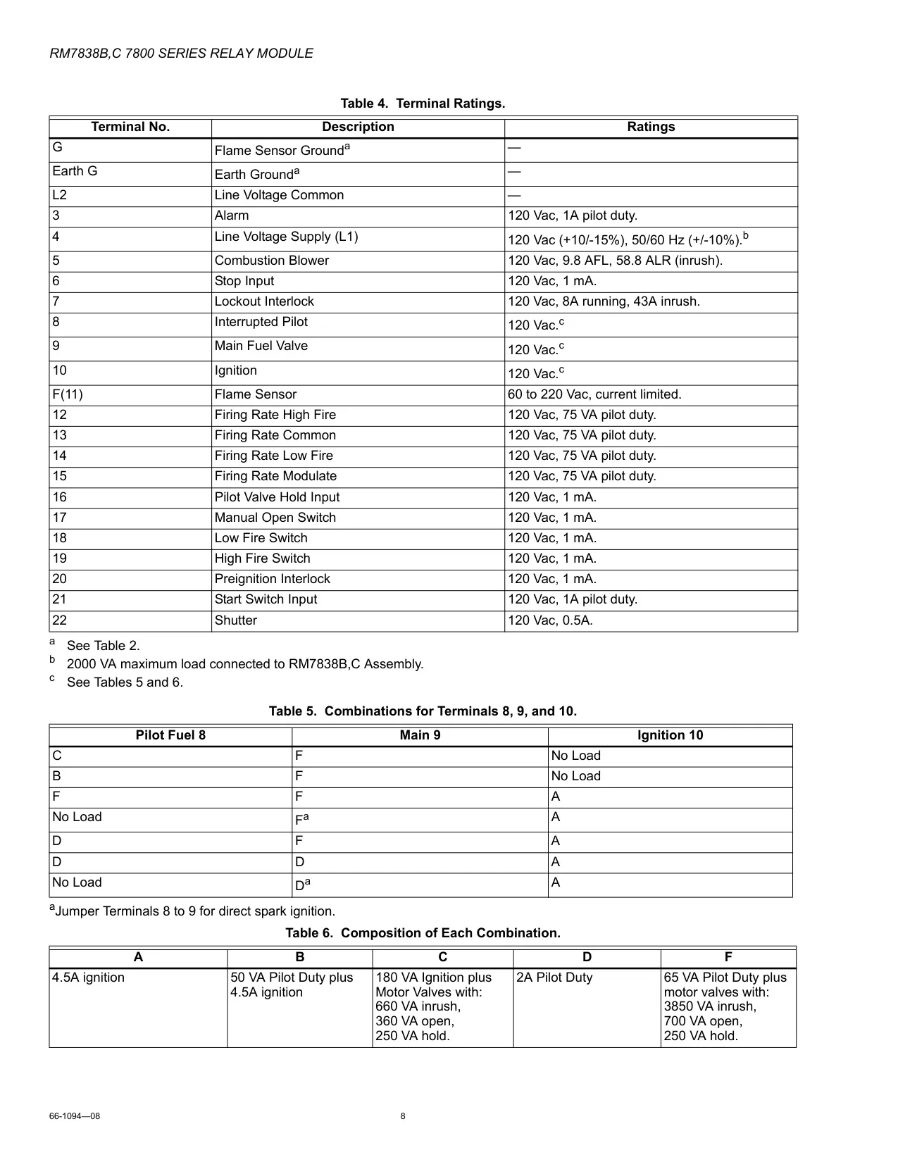
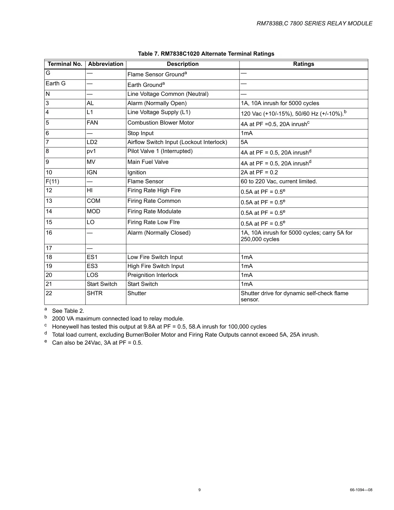
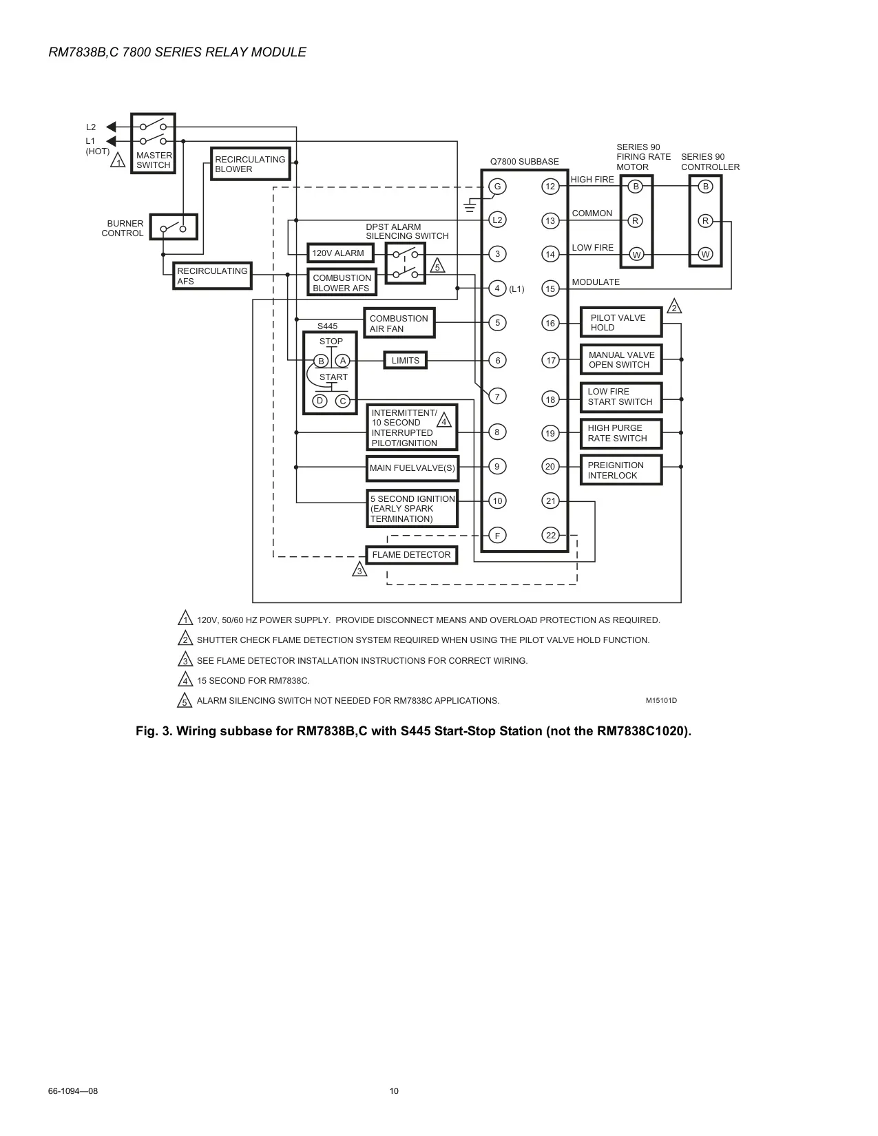
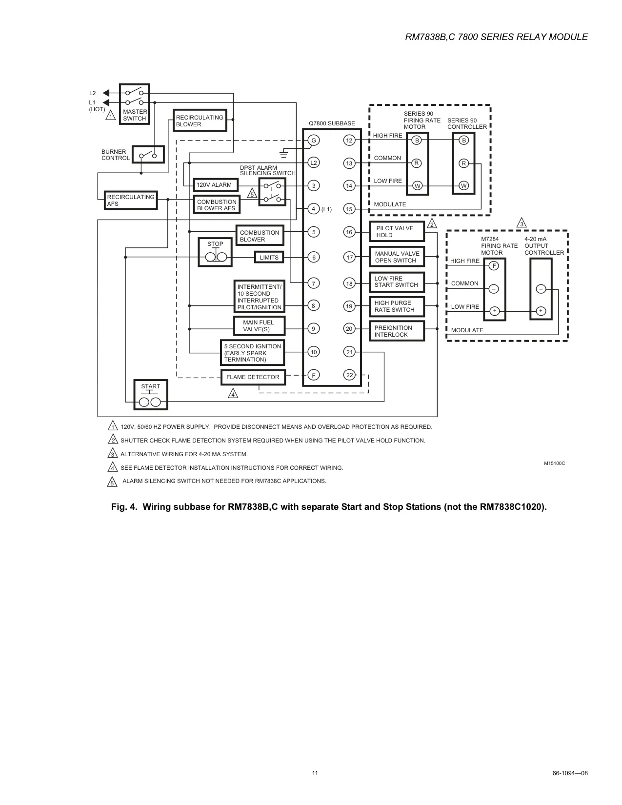
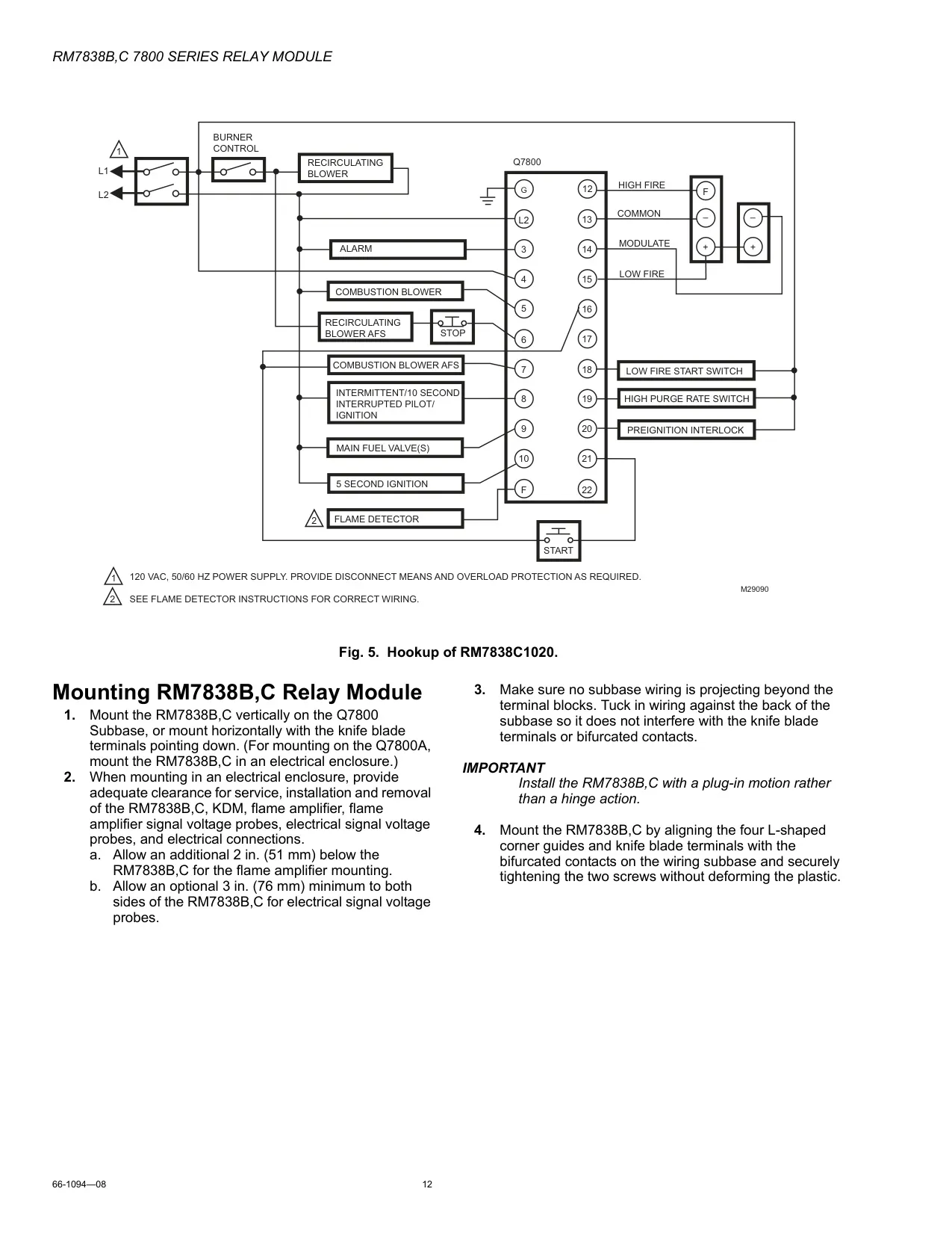
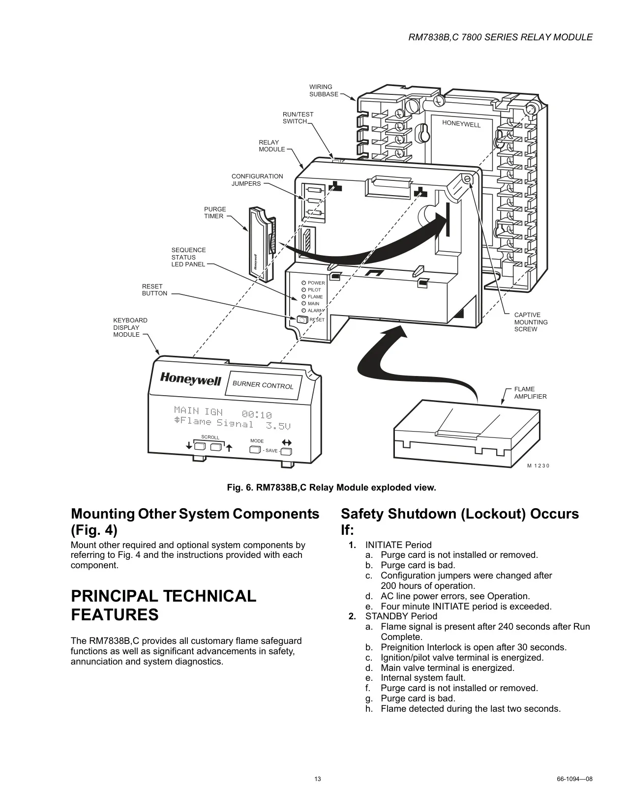
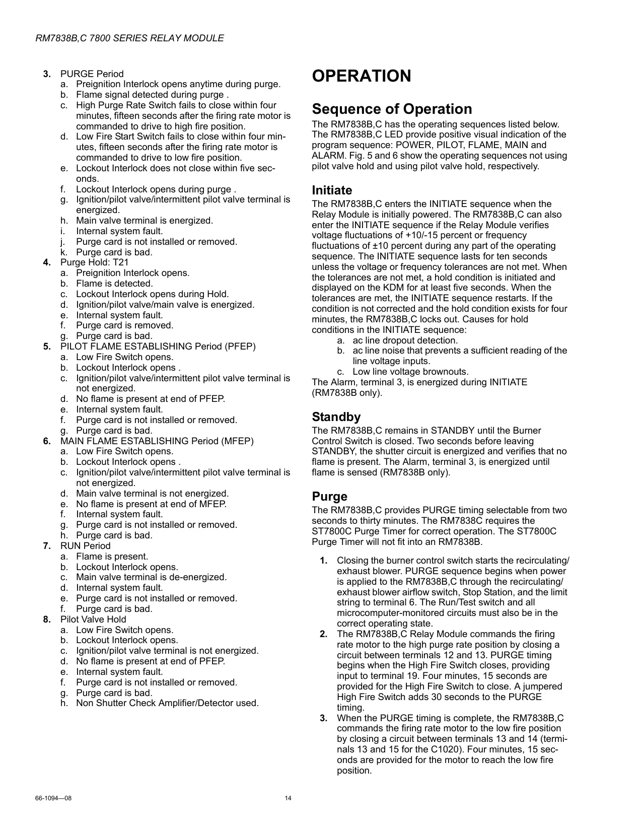
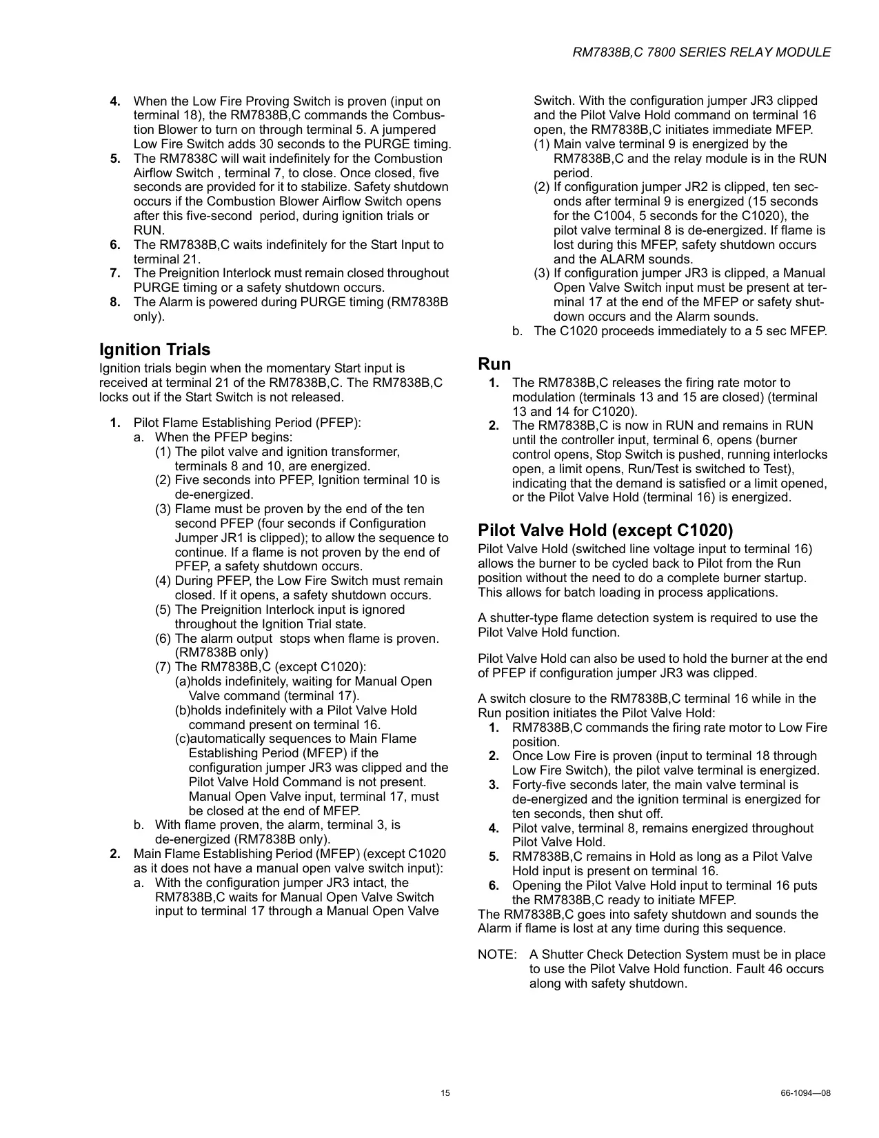

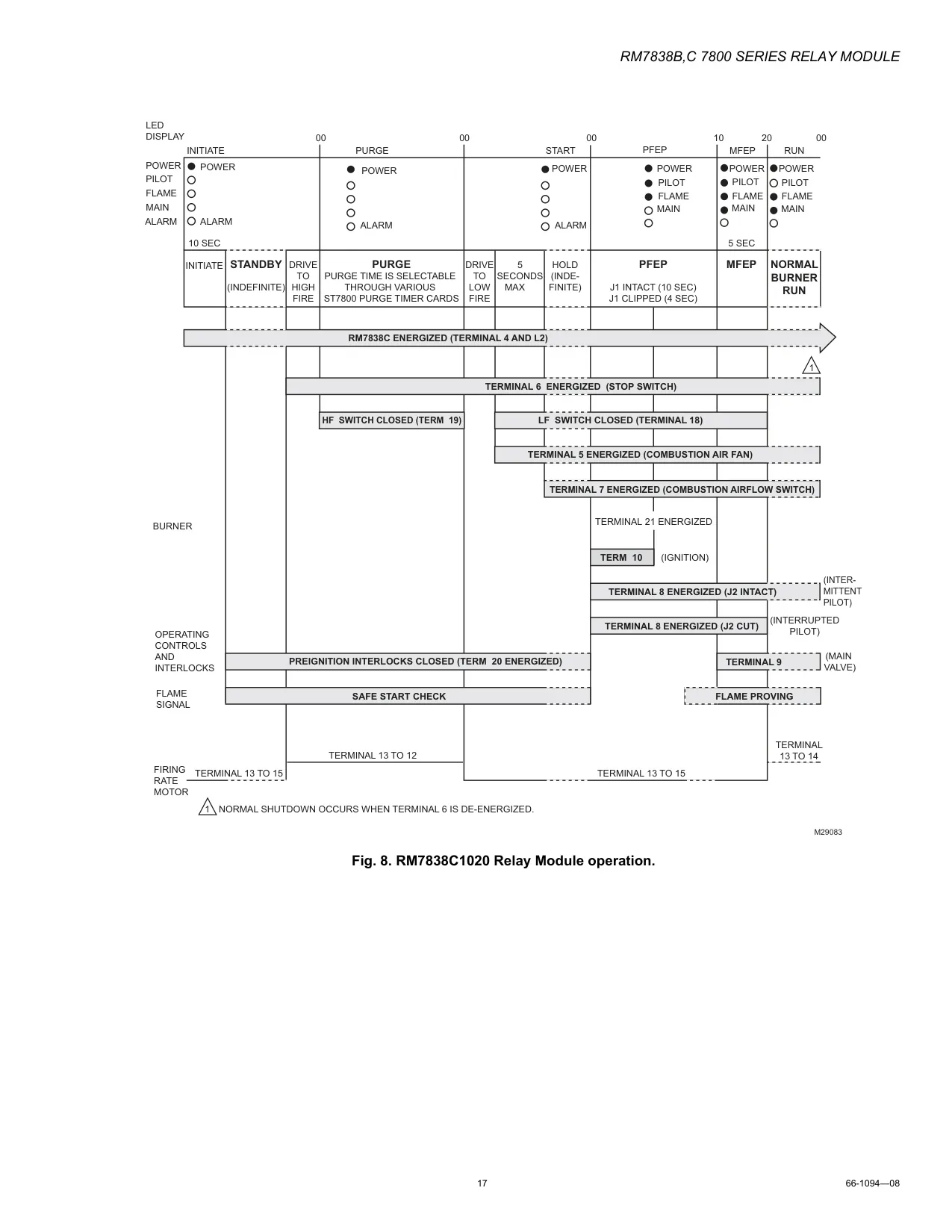

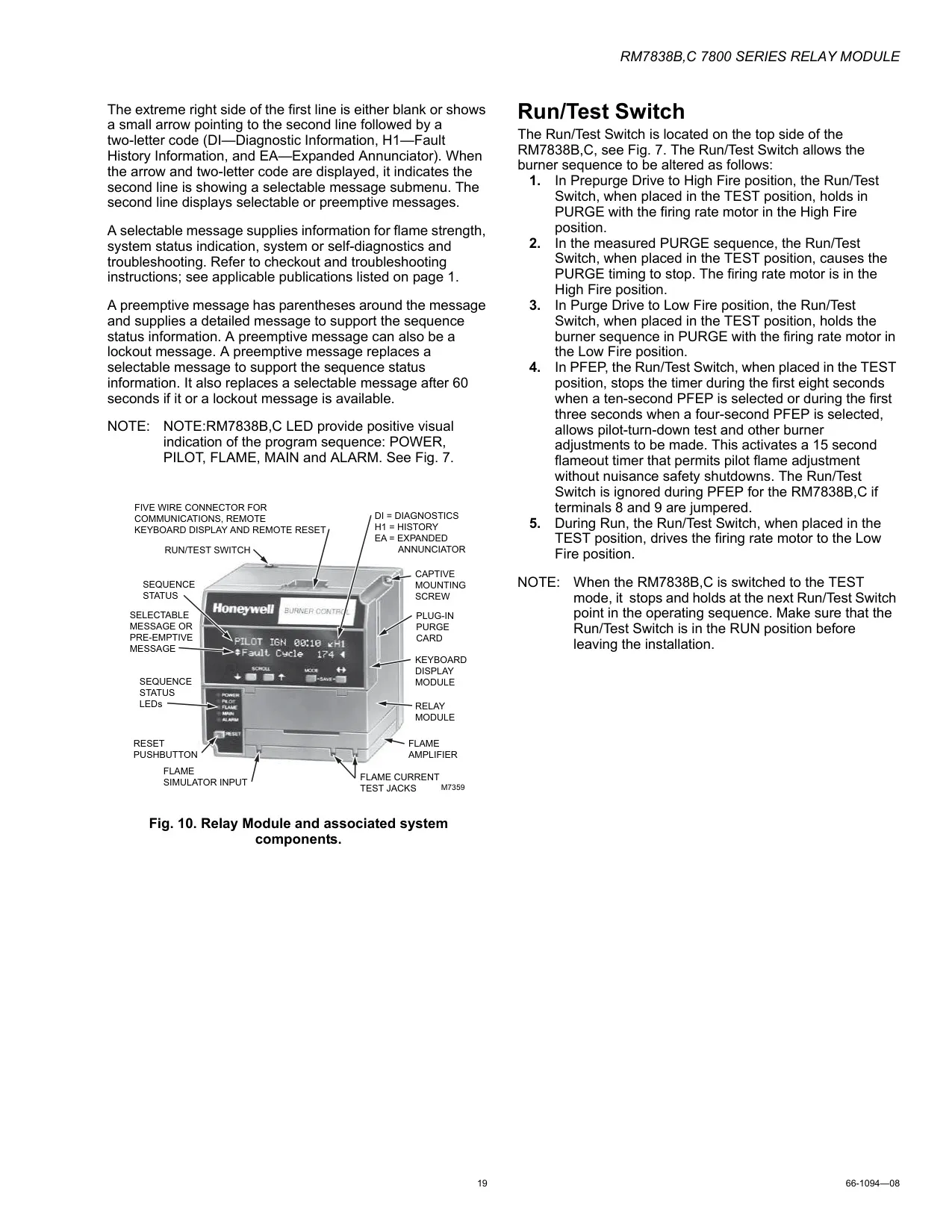


Honeywell RM7800 Burner Control

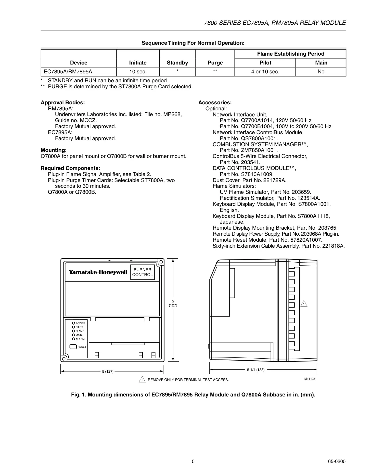
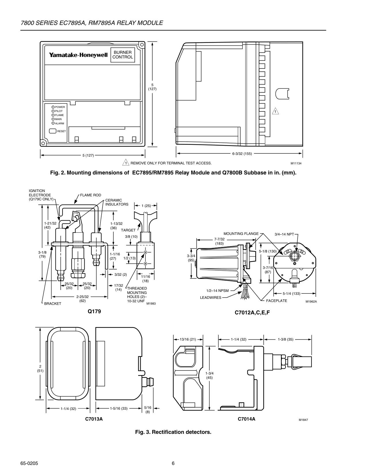
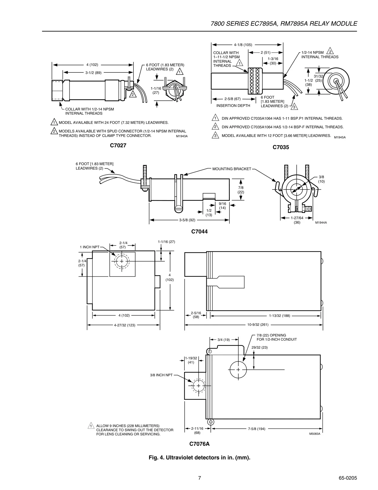
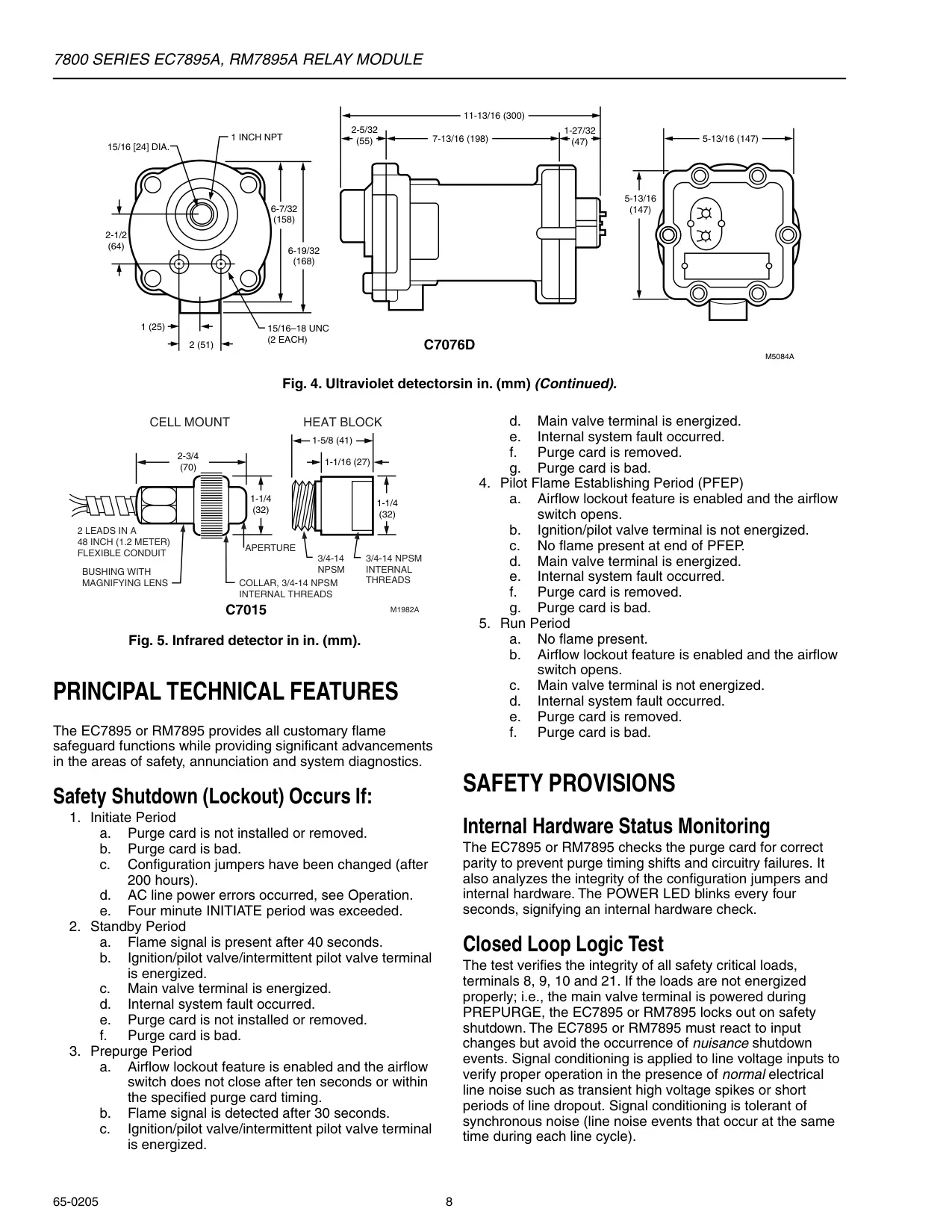
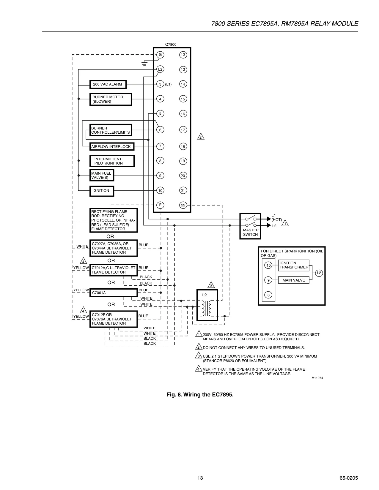
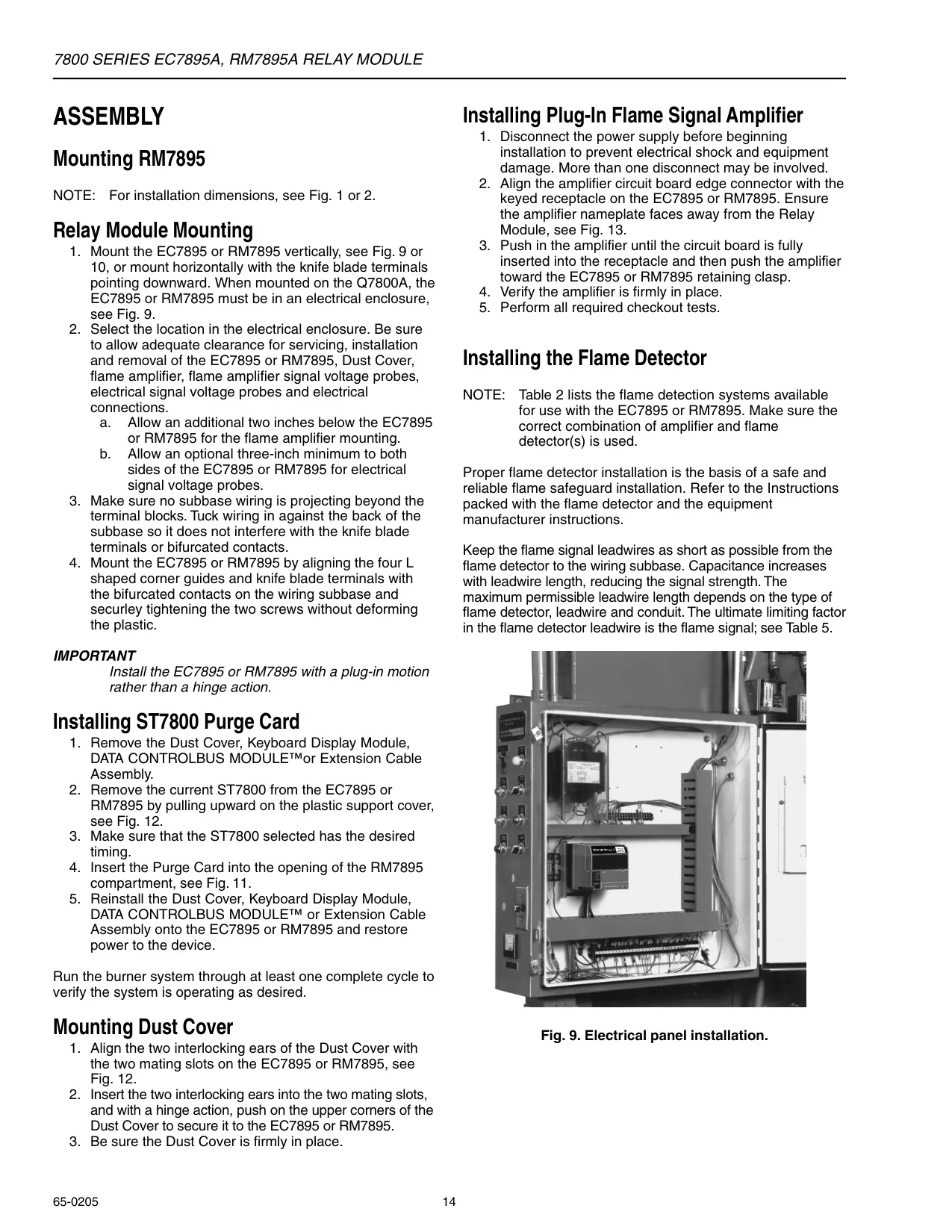
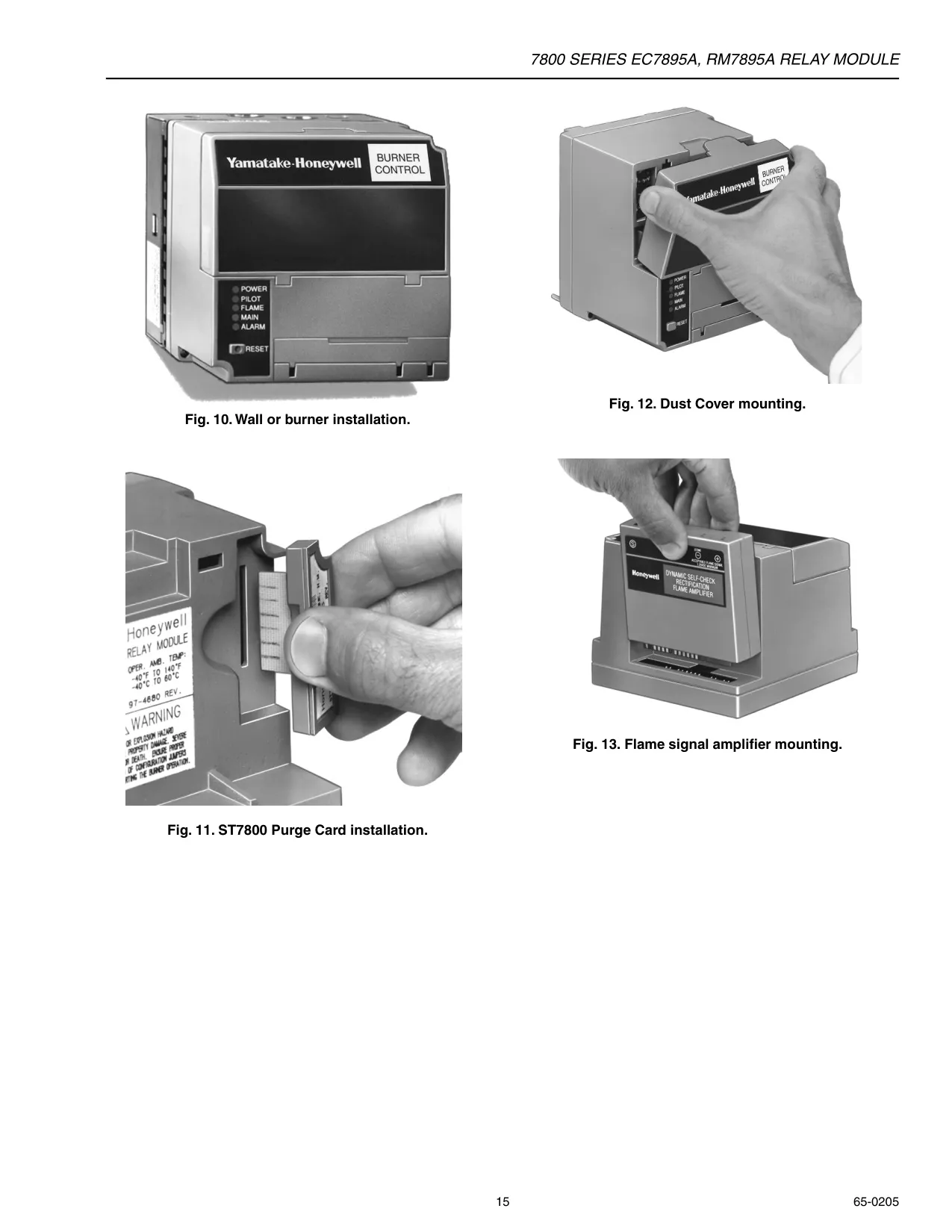
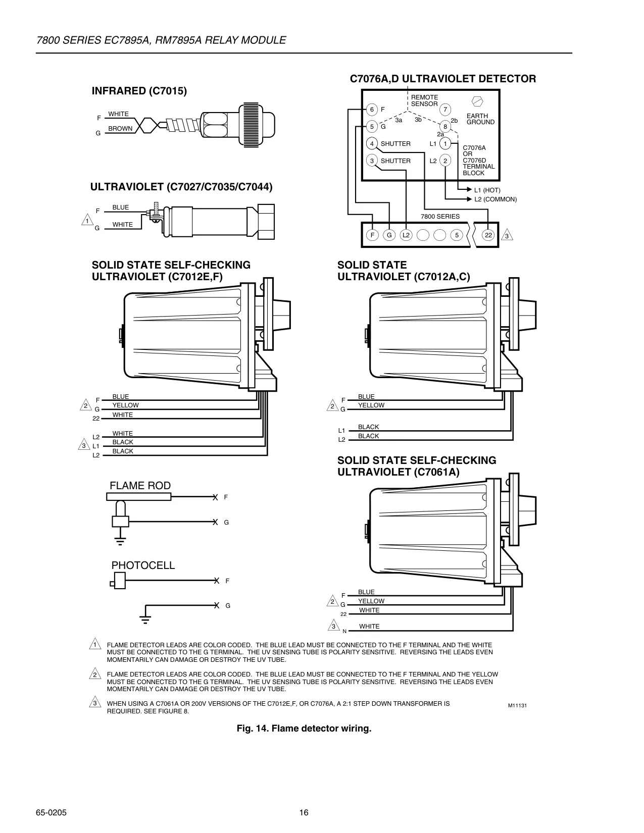


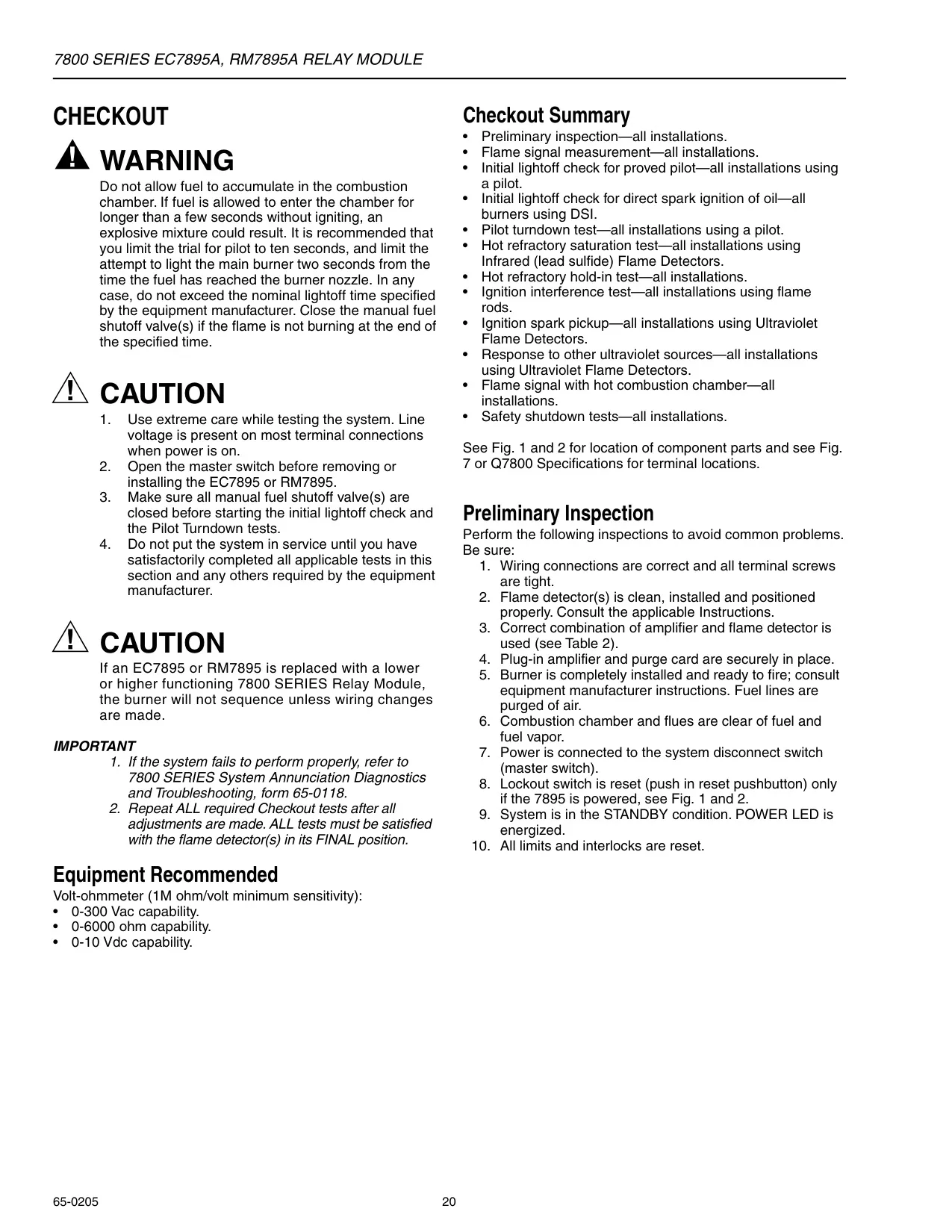
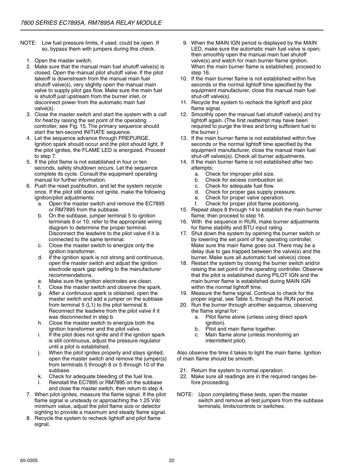

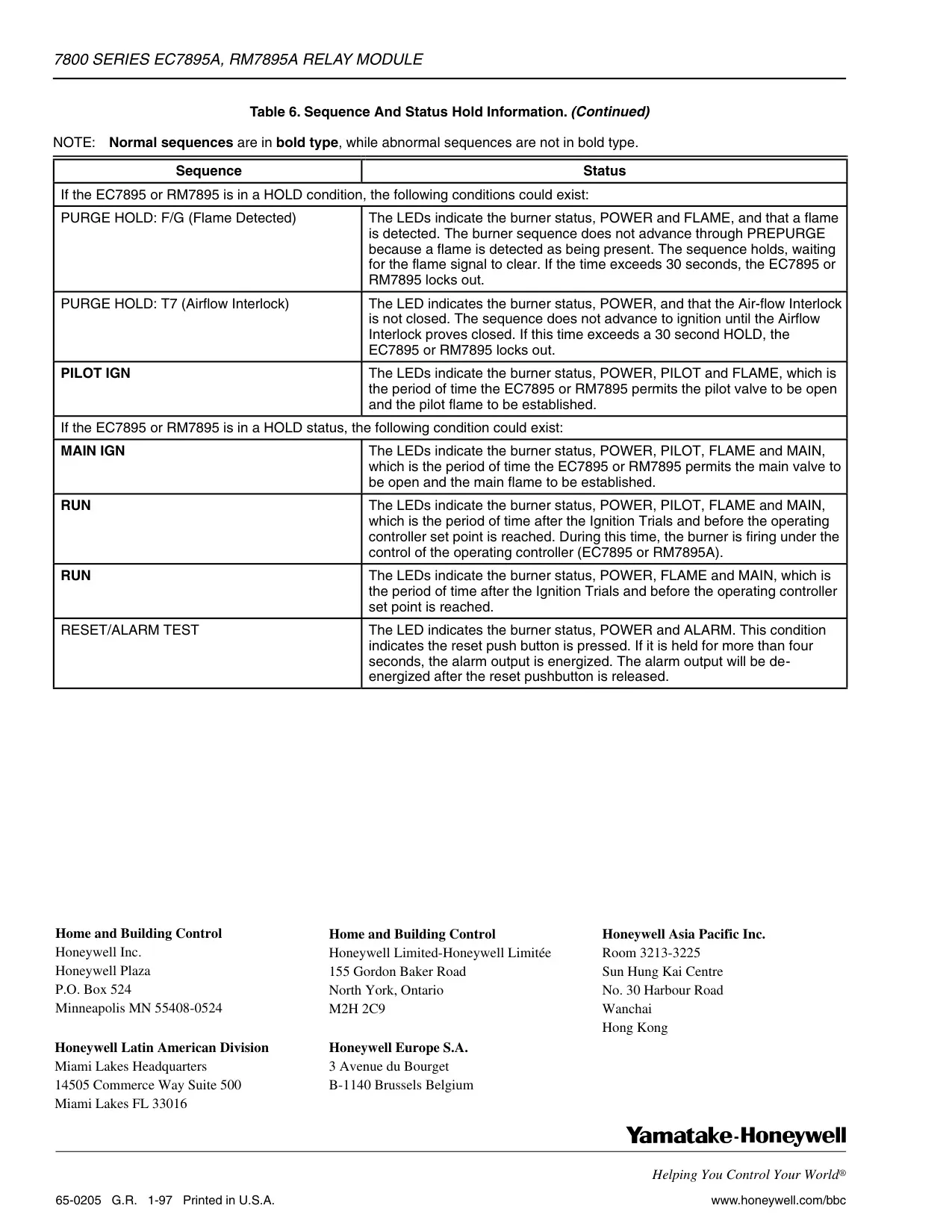
Honeywell RM7800 Instructions
Here we offer the Honeywell RM7800 Burner Control manual completely free and in English. We have cataloged this manual in the Burner Controls section on Manualverse, and it has been rated by 1 users with an average rating of 5. If you have any specific questions about Honeywell RM7800 Burner Control, we suggest checking the Frequently Asked Questions (FAQs) section of this manual.
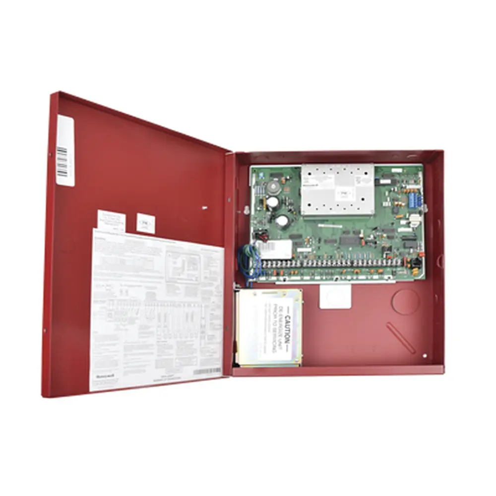
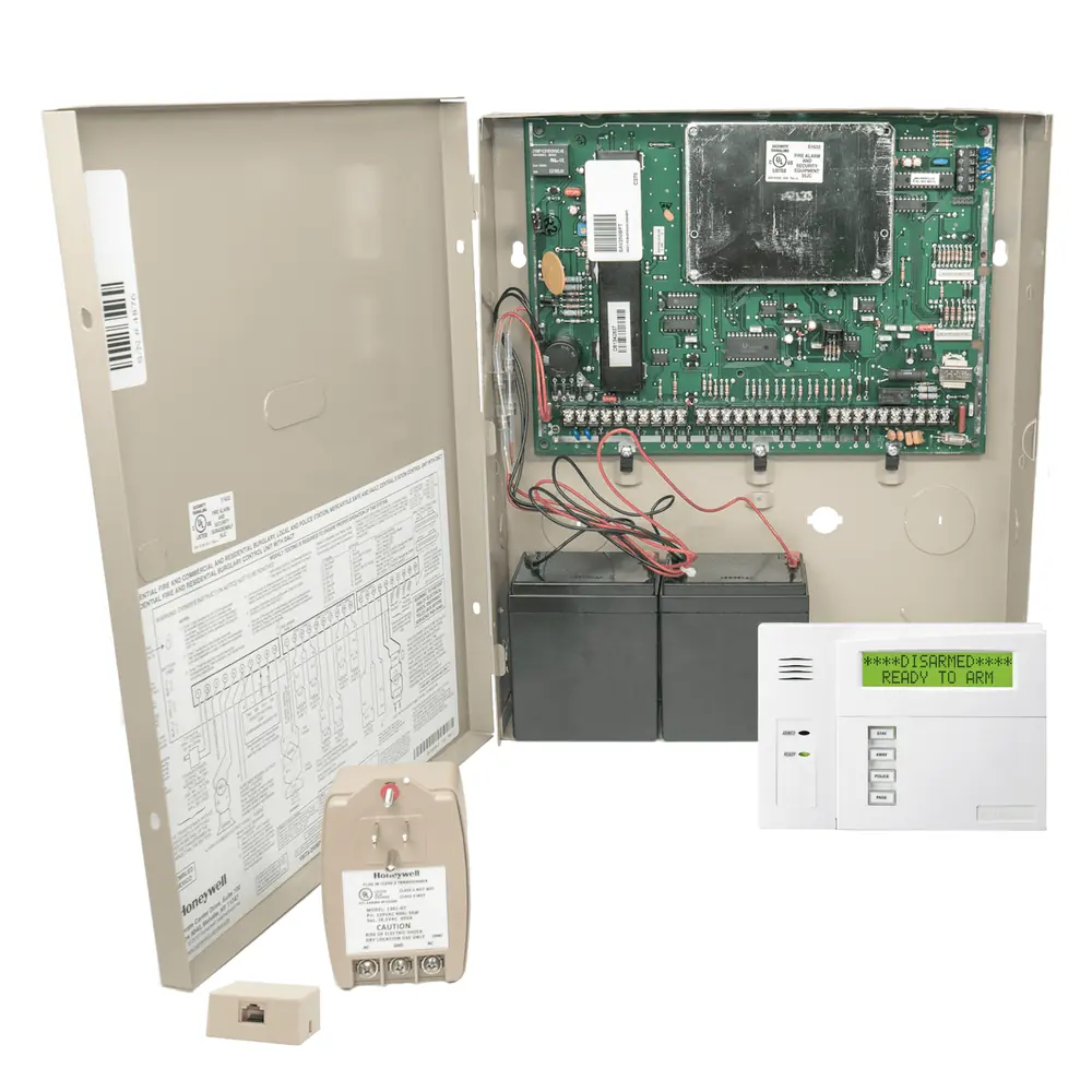
Product Images
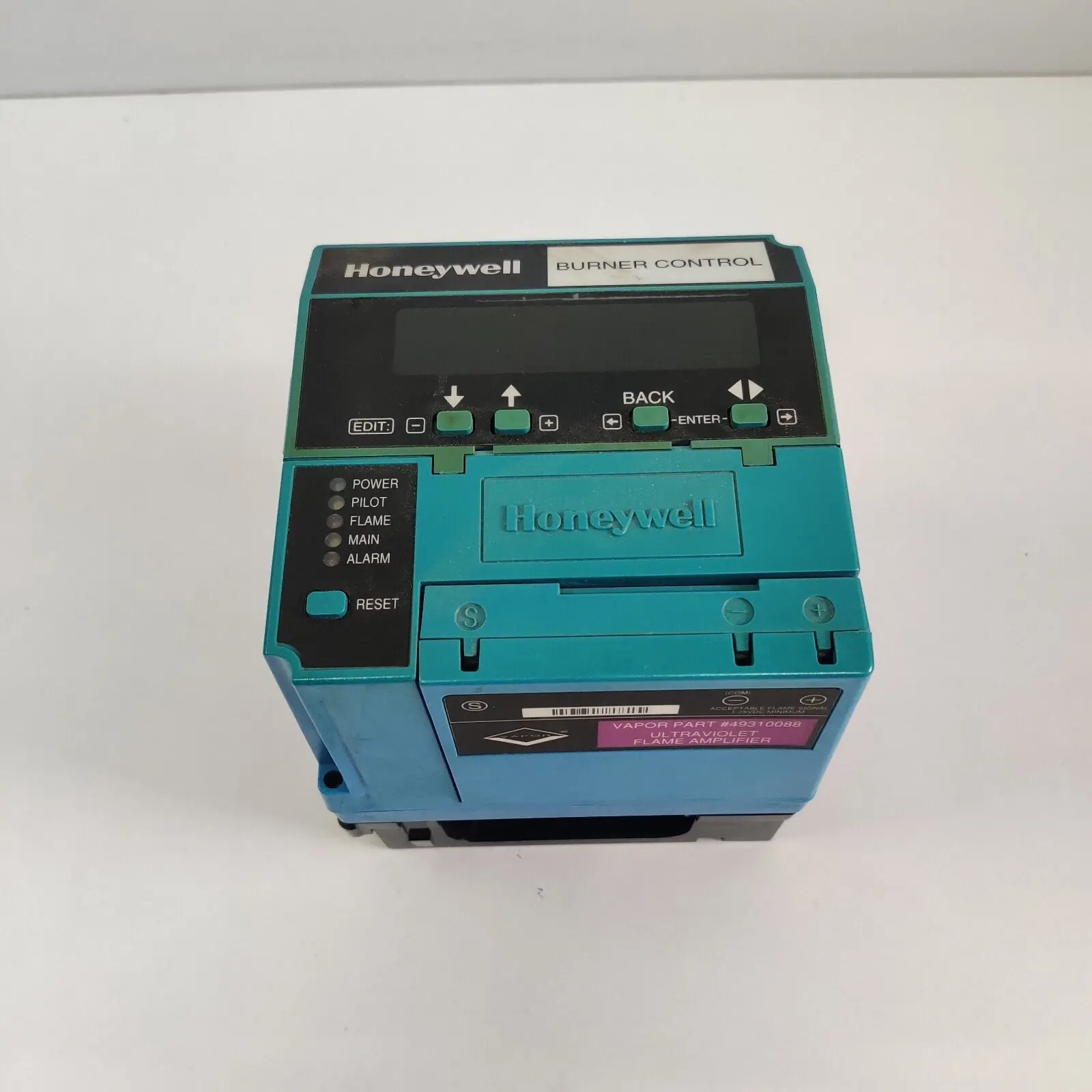
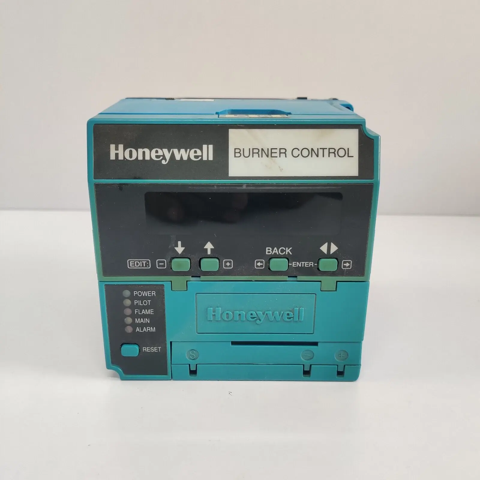
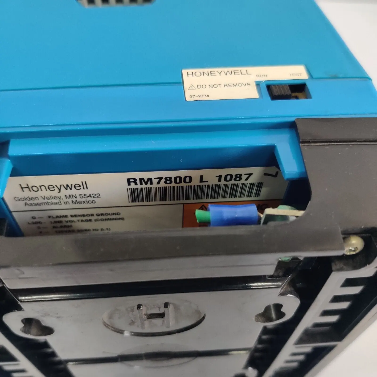
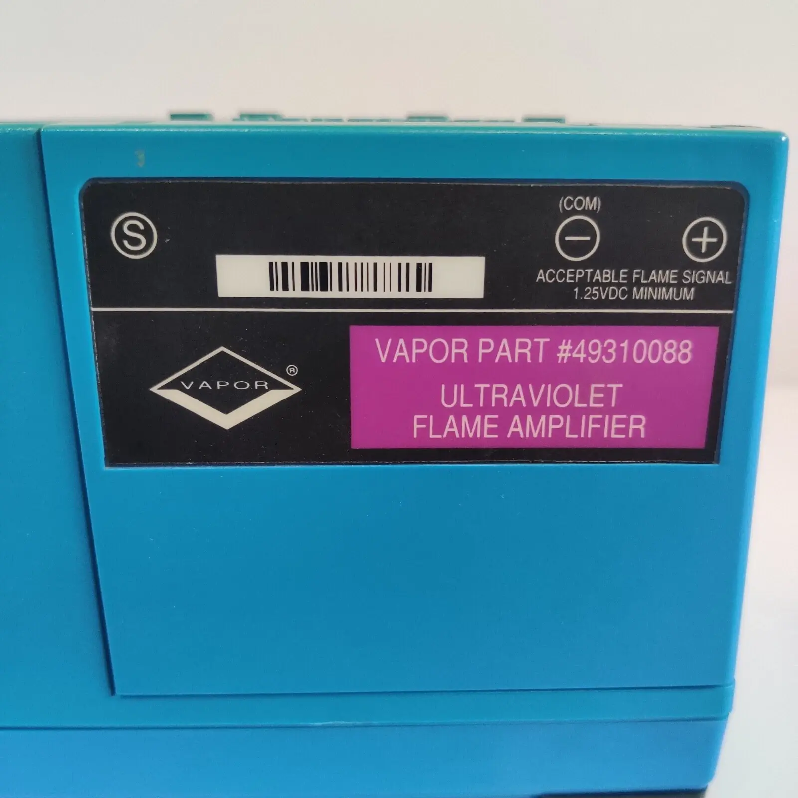

Honeywell RM7800 Burner Control Specifications
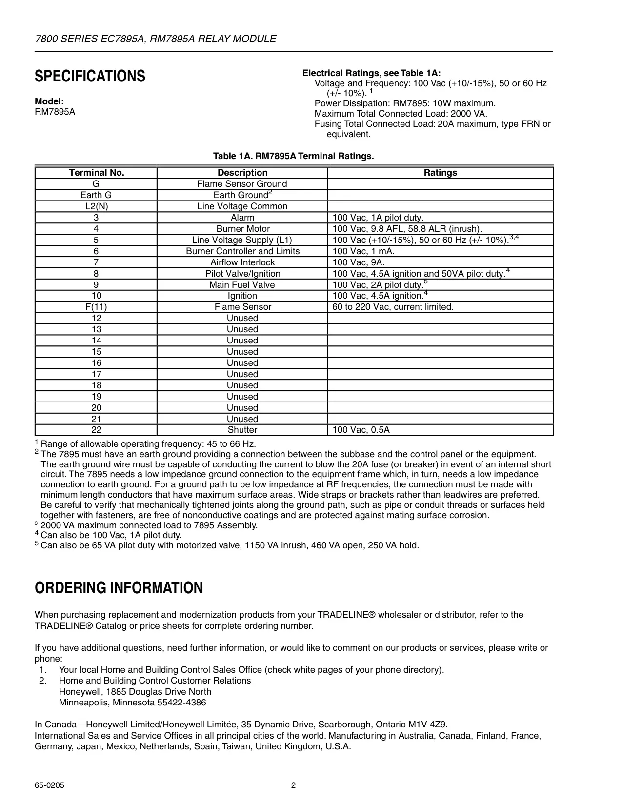
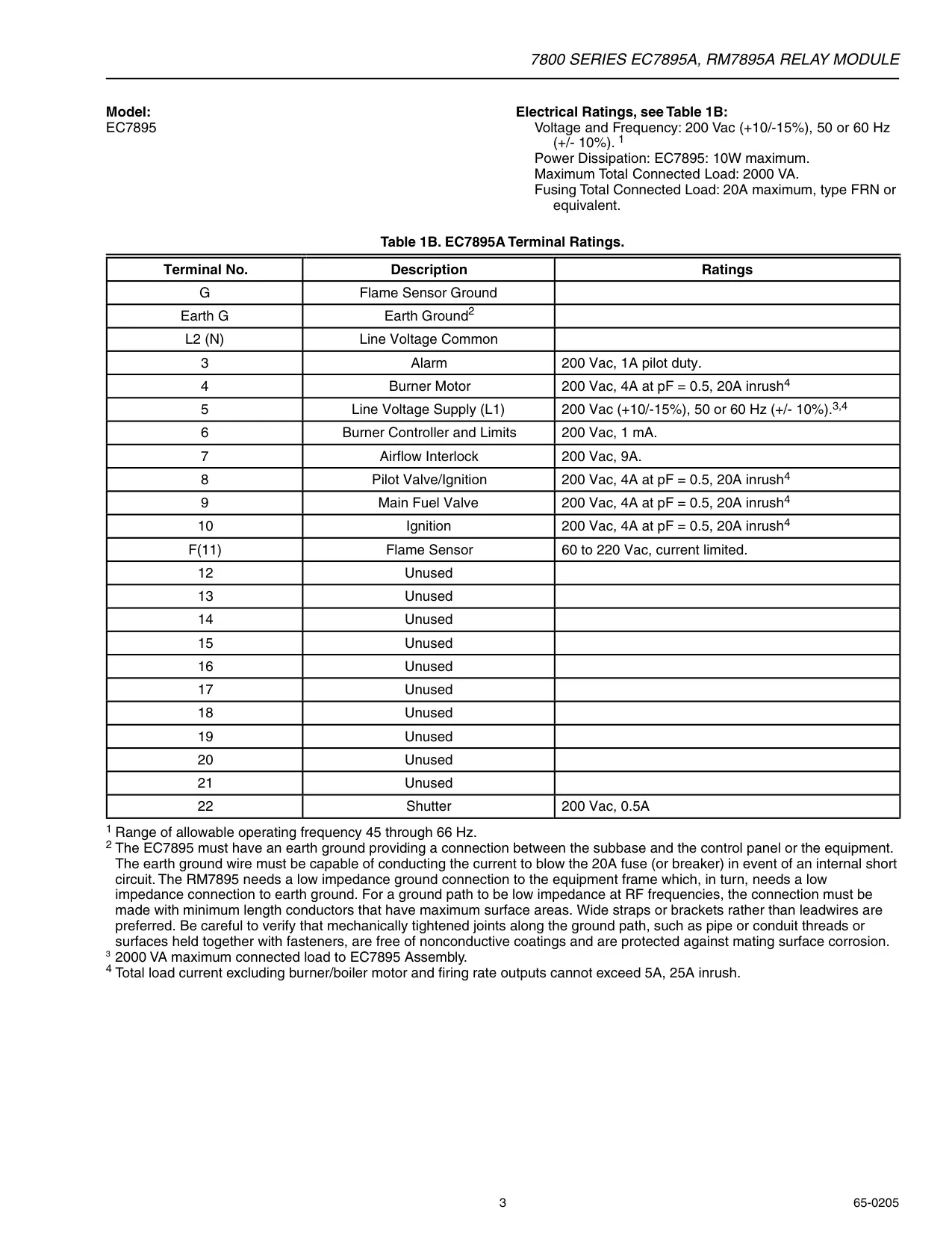
| Feature | Specification (RM7838B,C) | Notes for RM7838C1020 |
|---|---|---|
| General | ||
| Product Type | Microprocessor-based integrated burner control | |
| Application | Industrial process modulating semiautomatically fired gas, oil, coal or combination fuel single burner | |
| Power Dissipation | 10W maximum | |
| Max. Total Connected Load | 2000 VA | |
| Electrical Ratings | ||
| Voltage & Frequency | 120 Vac (+10/-15%), 50/60 Hz (±10%) | |
| Fusing Total Connected Load | 15A maximum, type SC or equivalent, fast blow | |
| Environmental | ||
| Operating Temperature | -40°F to +140°F (-40°C to +60°C) | |
| Storage Temperature | -40°F to +150°F (-40°C to +66°C) | |
| Humidity | 85% relative humidity continuous, noncondensing | |
| Vibration | 0.5G environment | |
| Safety & Approvals | ||
| SIL Capability | SIL 3 Capable (in a properly designed Safety Instrumented System) | |
| Approvals | UL Listed, CSA Certified, FM Approved, Swiss Re (IRI), FCC Part 15 Class B Emissions | Gastec (EN298, Report 115679/4) also applicable |
| Operational Distinctions | ||
| Pilot Valve Hold Functionality | Yes | Not available |
| Manual Open Valve Switch | Yes | Not available |
| Main Flame Establishing Period (MFEP) | 15 seconds (C1004) or 5 seconds (C1020) | 5 seconds |
| Purge Timer Requirement | Uses ST7800A,C Plug-In Purge Timer | Requires ST7800C Purge Timer |
| Alarm Behavior | Alarms on Safety Shutdown and during INITIATE, STANDBY, PURGE (RM7838B only) | Alarms only on Safety Shutdown |
| Key Terminal Ratings (120 Vac) | ||
| Terminal 3 (Alarm) | 1A pilot duty | 1A, 10A inrush for 5000 cycles (Normally Open) |
| Terminal 5 (Combustion Blower) | 9.8 AFL, 58.8 ALR (inrush) | 4A at PF = 0.5, 20A inrush |
| Terminal 8 (Interrupted Pilot/PV1) | 4A at PF = 0.5, 20A inrush | |
| Terminal 9 (Main Fuel Valve) | 4A at PF = 0.5, 20A inrush | |
| Terminal 10 (Ignition) | 2A at PF = 0.2 | |
| Terminal F(11) (Flame Sensor) | 60 to 220 Vac, current limited | |
| Terminal 22 (Shutter) | 0.5A | Shutter drive for dynamic self-check flame sensor |
Honeywell RM7800 Burner Control Details
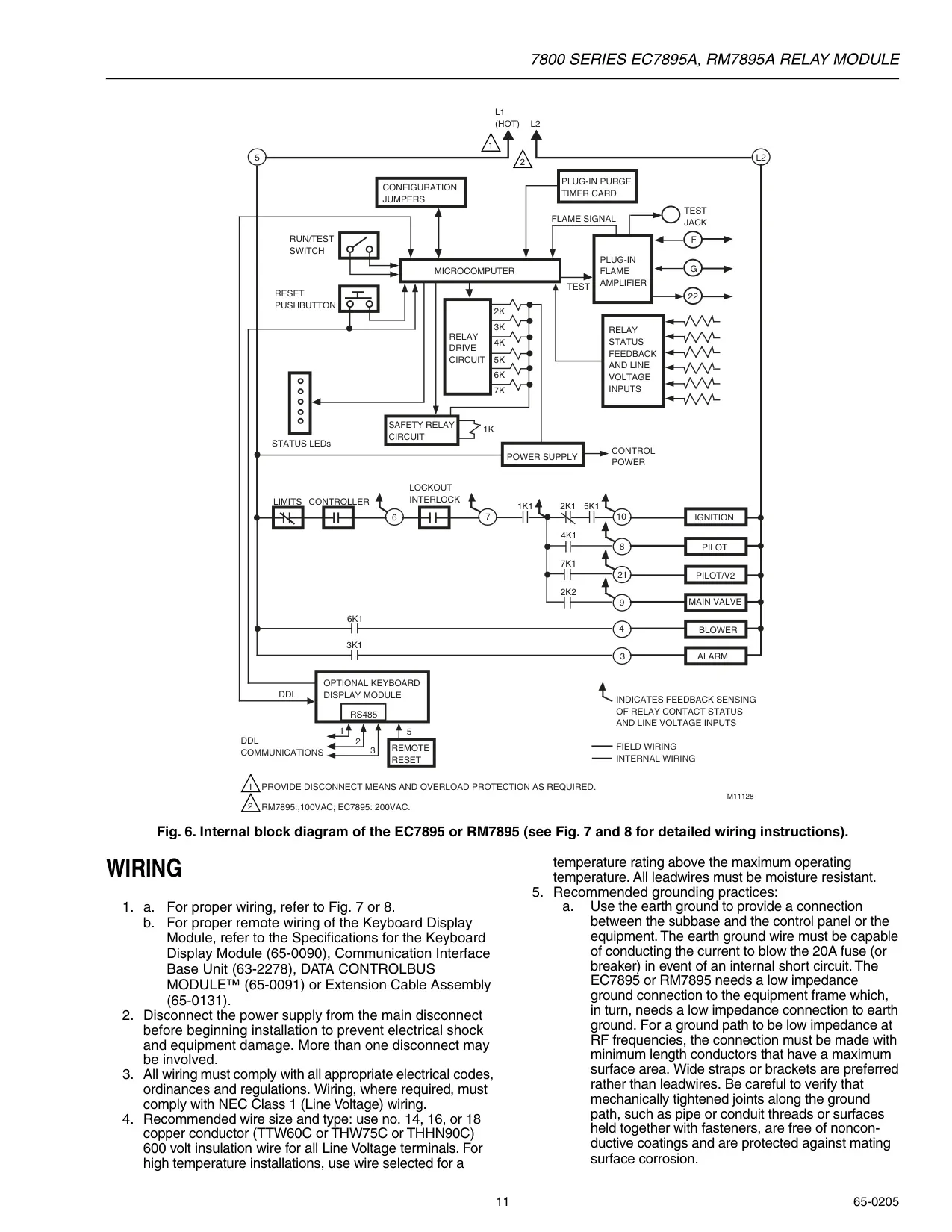
The Honeywell RM7838B,C is a sophisticated microprocessor-based integrated burner control system, designed for industrial process modulating, semi-automatically fired single burner applications utilizing gas, oil, coal, or combination fuels. This advanced system comprises a relay module, wiring subbase, Keyboard Display Module (KDM), a compatible amplifier, and a dedicated purge card. Optional enhancements include a Data ControlBus Module™, remote display mounting, and an expanded annunciator for comprehensive fault reporting.
The primary functions of the RM7838B,C encompass automatic modulated High Fire and Low Fire proven purge cycles, ensuring safe combustion chamber conditions before ignition. It manages burner pilot startup, featuring a special pilot valve hold capability from the Run condition, which is particularly useful for batch processes. The system provides continuous flame supervision, critical for operational safety, alongside clear system status indications and robust self-diagnostics for efficient troubleshooting.
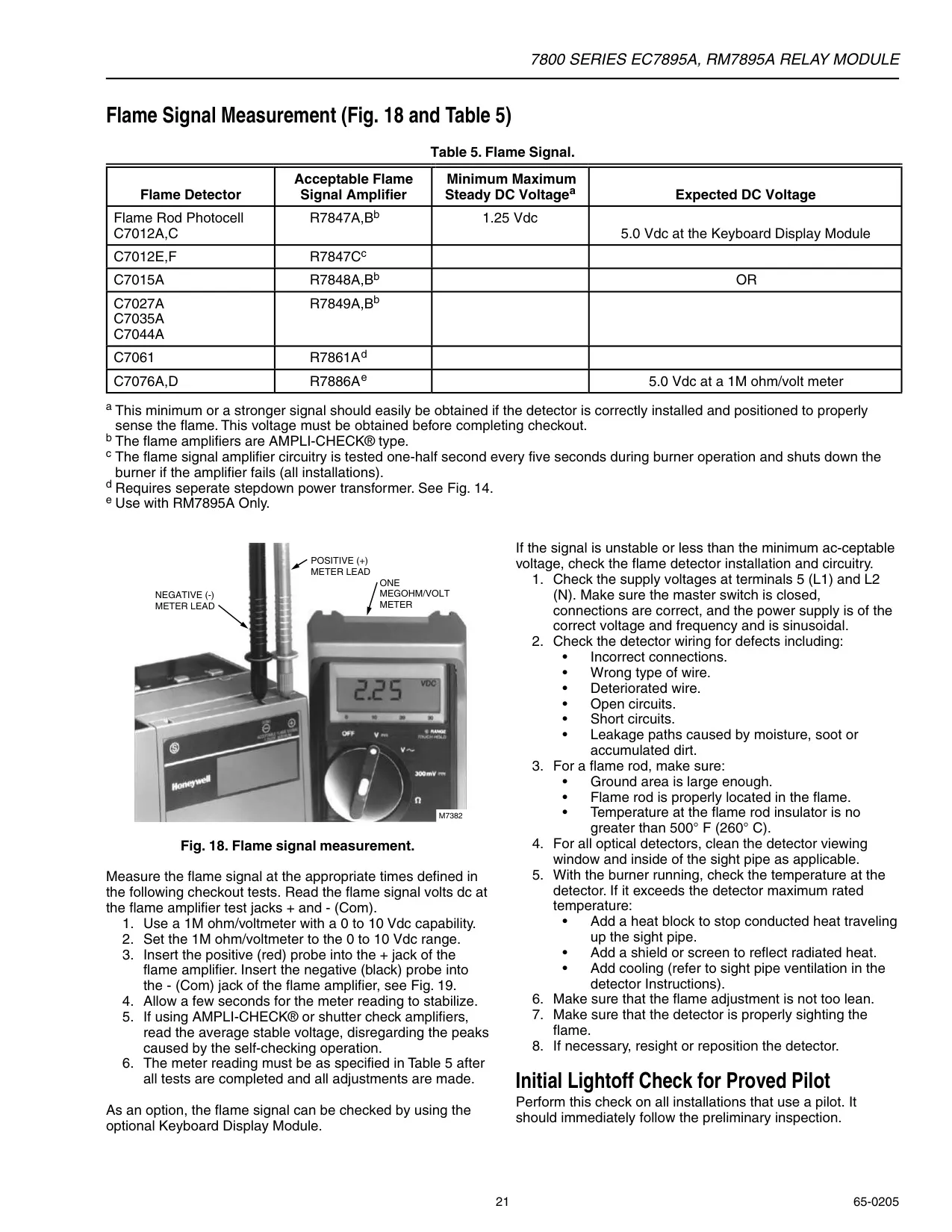
A key component is the Keyboard Display Module (KDM), offering first-out annunciation and detailed system diagnostics. Its 2-row by 20-column Vacuum Fluorescent Display (VFD) shows the current burner sequence (e.g., STANDBY, PURGE, RUN), precise timing information, and status for holds or lockouts, including fault codes. The KDM also provides selectable messages for crucial data like flame strength and historical fault information, aiding in quick diagnosis and system understanding.
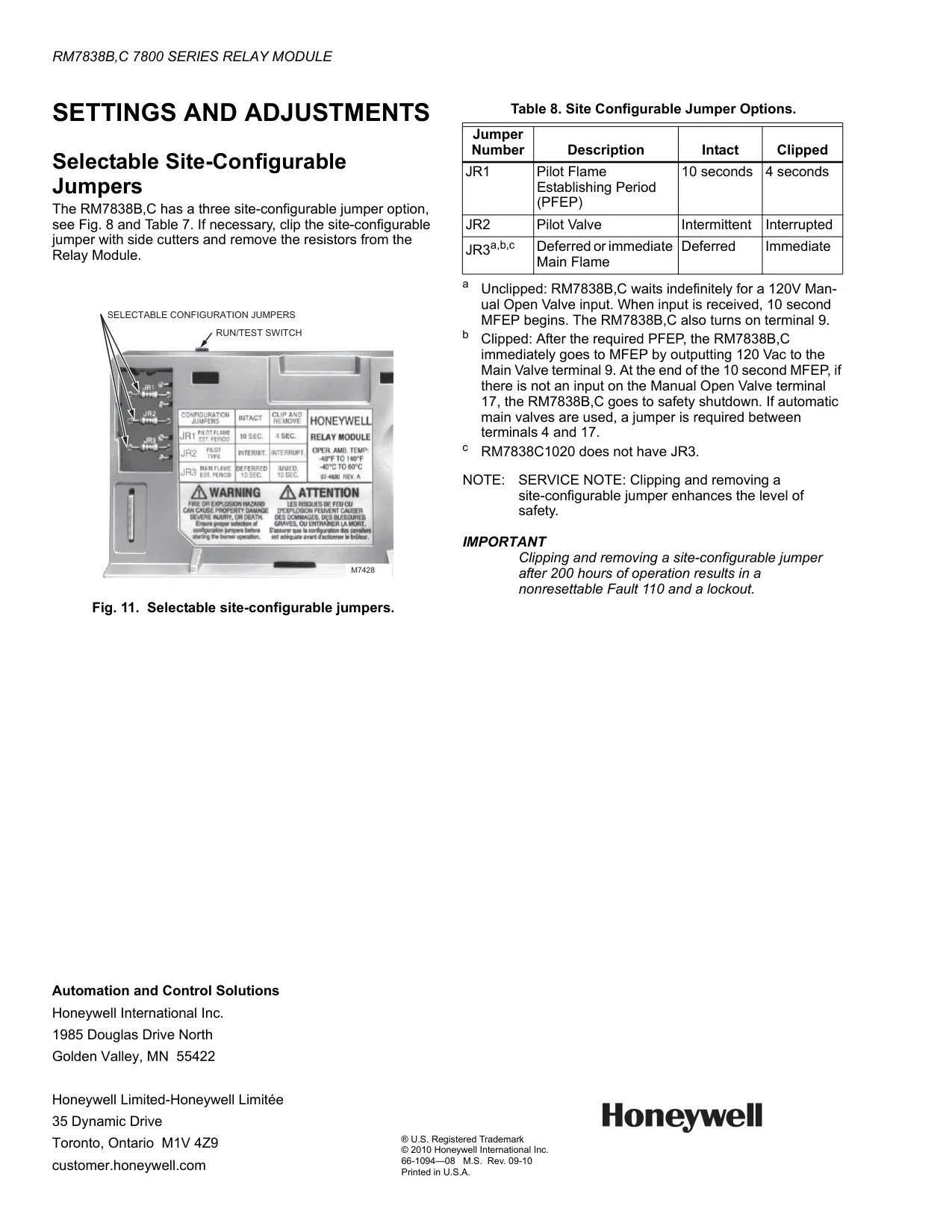
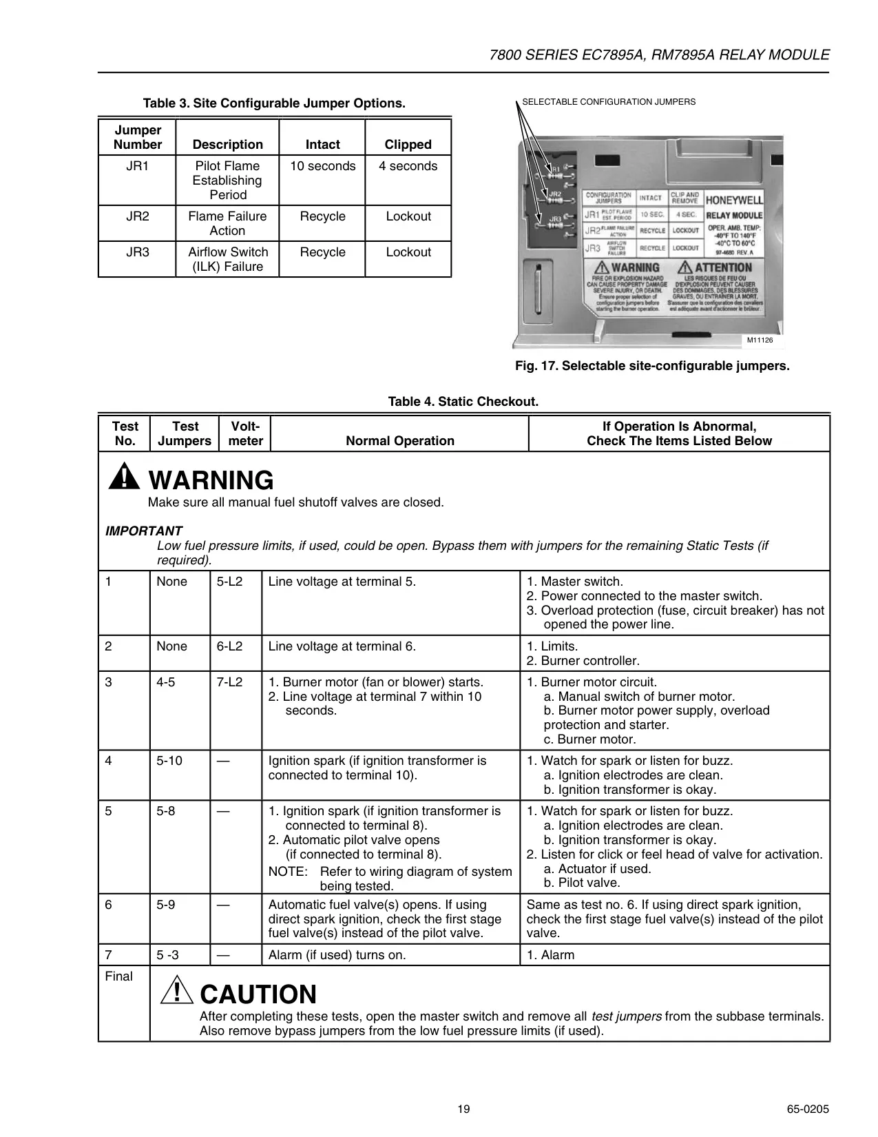
For maintenance and testing, the system includes a convenient Run/Test Switch. This switch allows technicians to alter the burner sequence, for instance, by holding the system in PURGE at either High or Low Fire, or pausing the Pilot Flame Establishing Period (PFEP) for pilot-turn-down tests. The RM7838B,C also features site-configurable jumpers (JR1, JR2, JR3) to select parameters like PFEP duration or pilot valve operation, providing essential application flexibility.
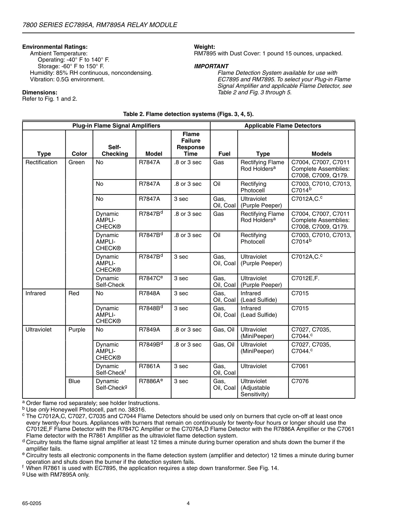
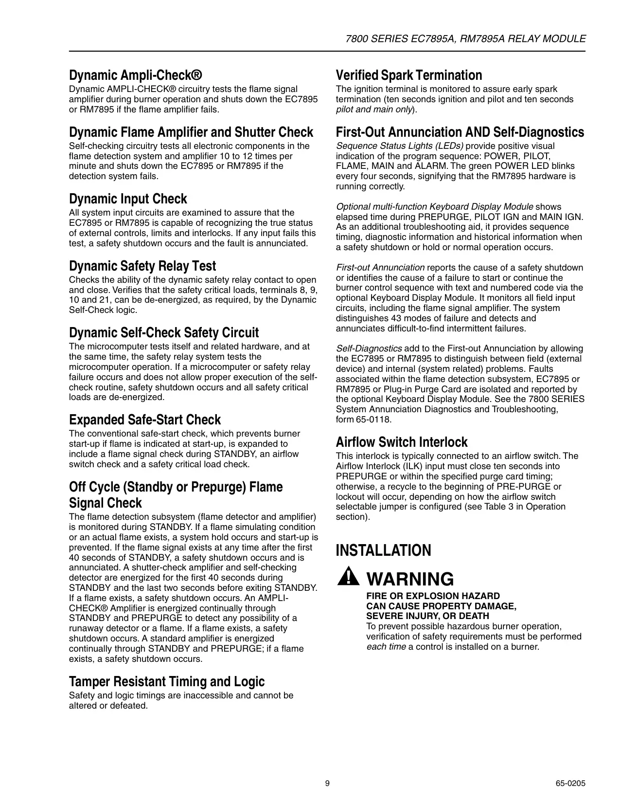
Beyond basic operation, the RM7838B,C incorporates numerous advanced safety provisions. These include dynamic self-check logic and hardware status monitoring, which continuously verify the integrity of critical components. Features like Dynamic AMPLI-CHECK® and Dynamic Input Check ensure the flame detection system and all external inputs are functioning correctly. Additionally, tamper-resistant timing and logic prevent unauthorized alterations to safety-critical parameters.
The control is designed to execute safety shutdowns across various operational periods, from INITIATE through RUN, if specific hazardous conditions are detected. These conditions range from AC line power errors and interlock failures to unexpected flame signals or burner component malfunctions. The system's comprehensive self-diagnostics, complemented by the KDM's first-out annunciation, precisely identifies the root cause of issues, distinguishing between field and internal system problems, which significantly reduces downtime.
Frequently Asked Questions (FAQs)
Can't find the answer you need? Here are some frequently asked questions about the Honeywell RM7800 Burner Control, and we answer them below.