Honeywell Aquastat L6006a Hydronic Controller Instruction Manual

Honeywell Aquastat L6006a Hydronic Controller




Honeywell Aquastat L6006a Hydronic Controller






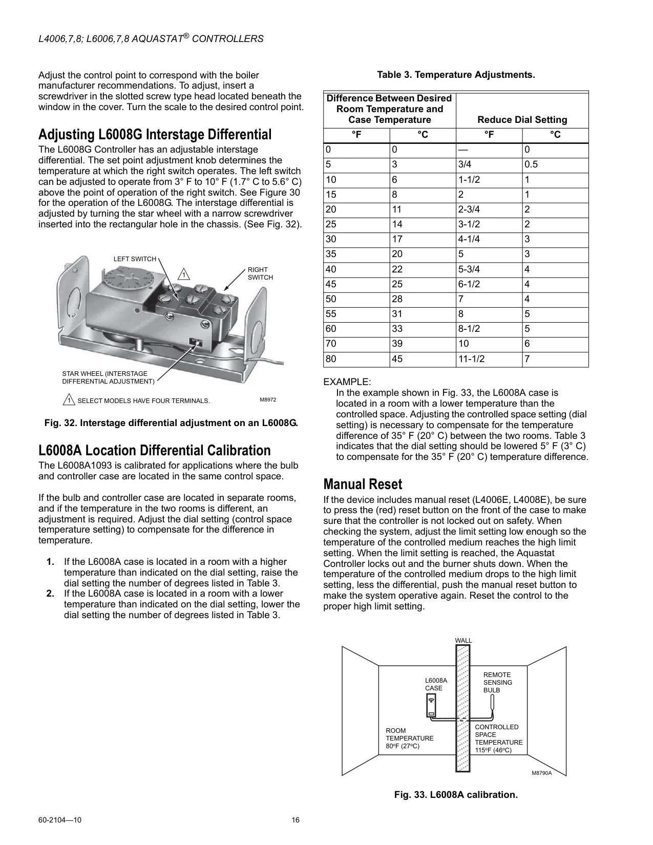

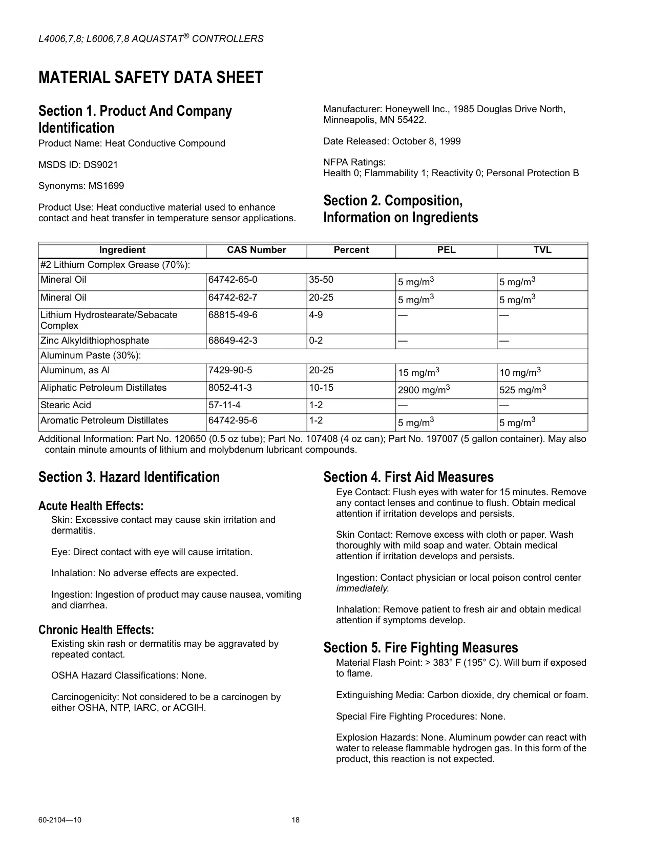


Honeywell Aquastat L6006a Instructions
Here we offer the Honeywell Aquastat L6006a Hydronic Controller manual completely free and in English. We have cataloged this manual in the Hydronic Controller section on Manualverse, and it has been rated by 1 users with an average rating of 5. If you have any specific questions about Honeywell Aquastat L6006a Hydronic Controller, we suggest checking the Frequently Asked Questions (FAQs) section of this manual.
Product Images
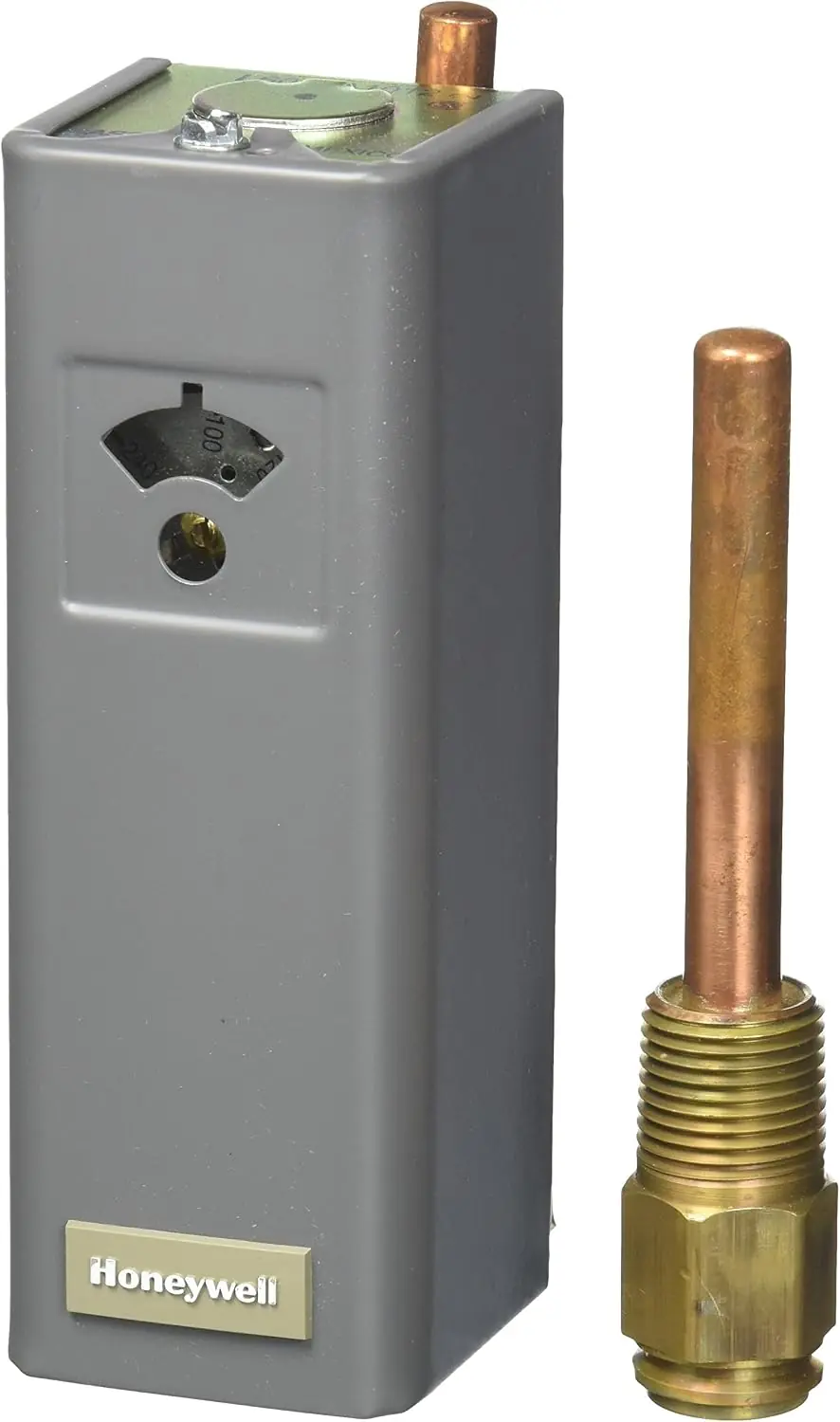
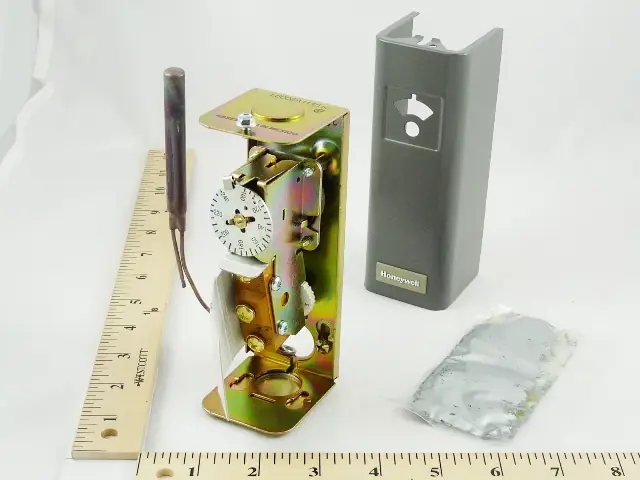
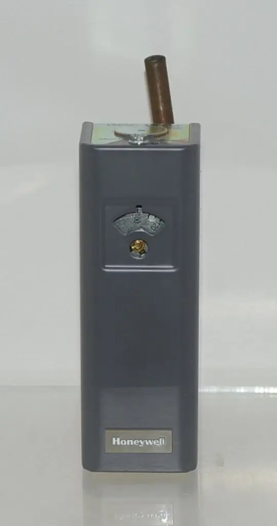
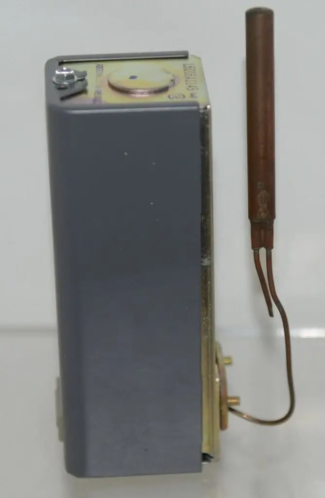
Honeywell Aquastat L6006a Hydronic Controller Specifications
| Feature | Specification |
|---|---|
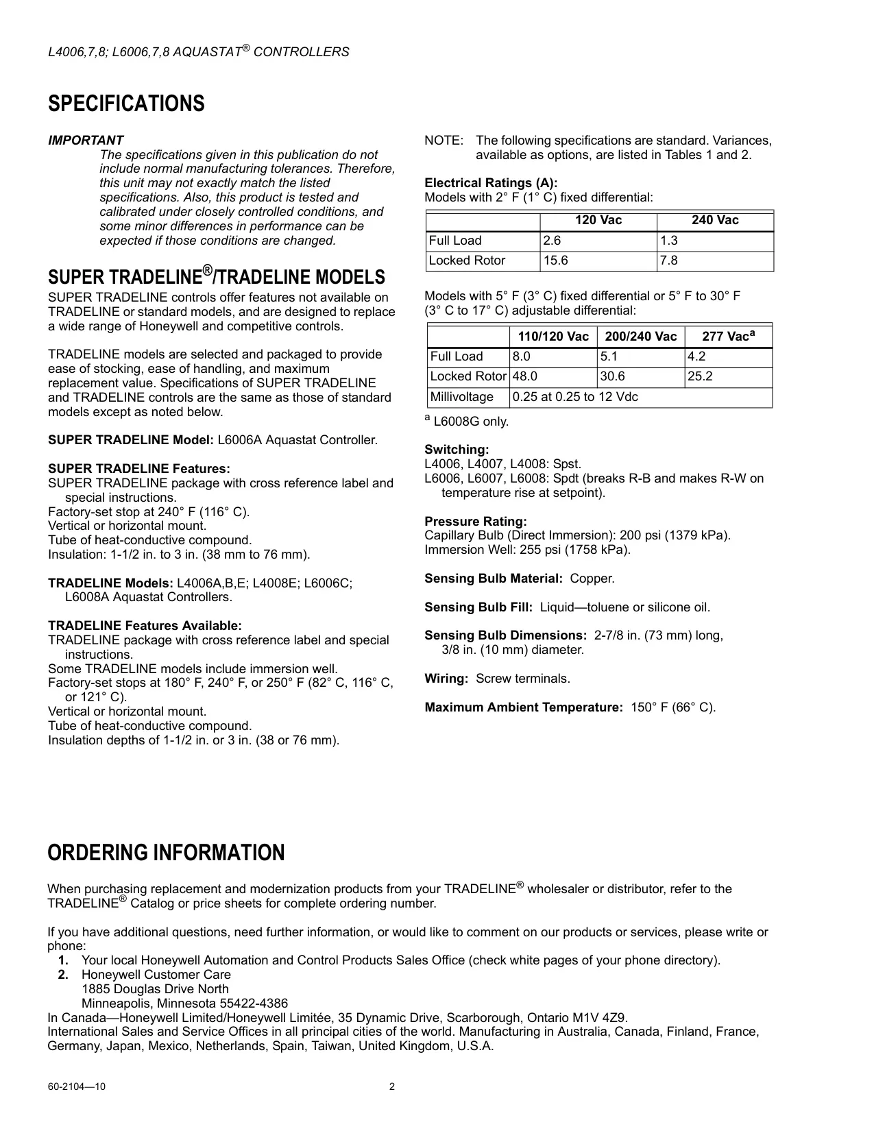
| Model | Honeywell L6006A Aquastat Controller (SUPER TRADELINE model) |
| Product Type | Immersion type hydronic temperature controller |
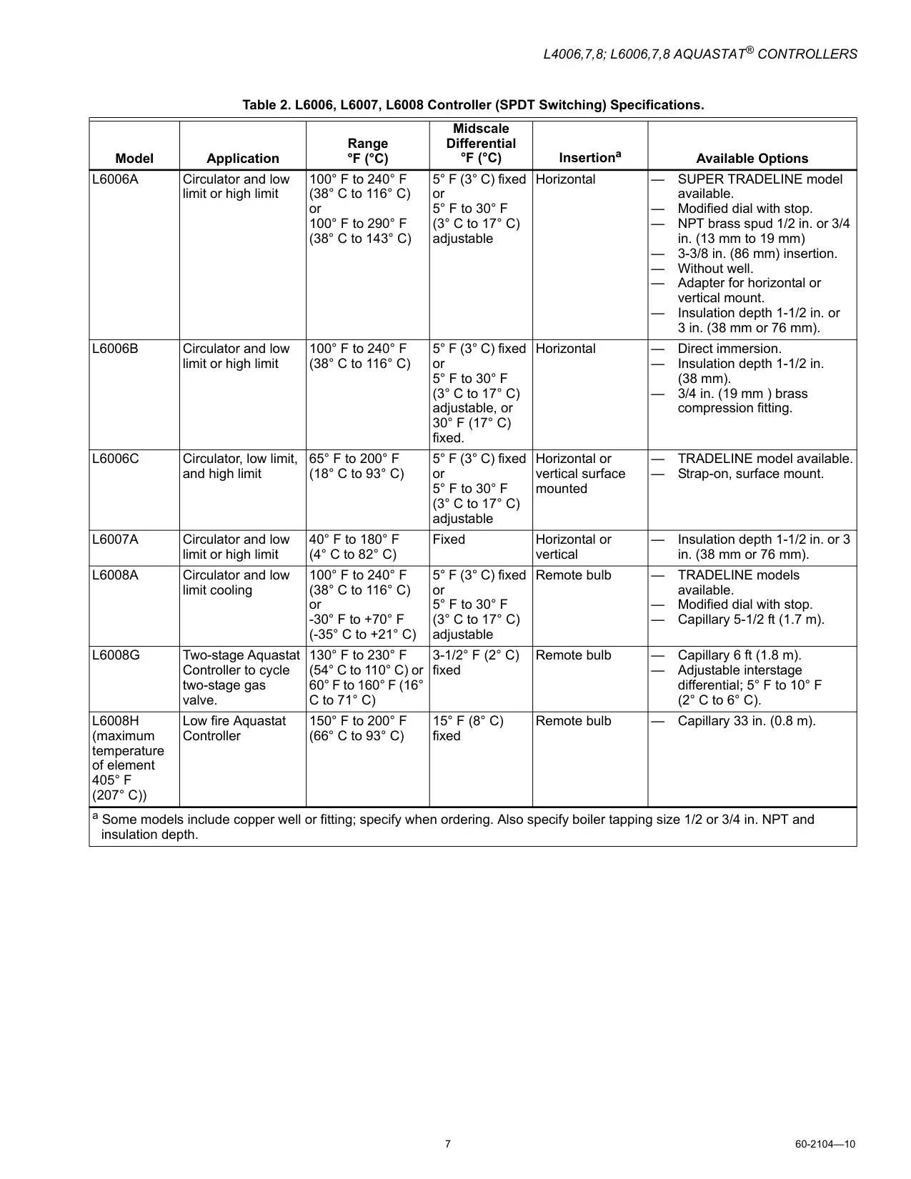
| Application | High limit, low limit or circulator control (circulator and low limit, or high limit) |
| Switching | SPDT: breaks R-B and makes R-W on temperature rise at setpoint |
| Switch Type | Totally enclosed Micro Switch snap-acting switch |
| Temperature Range | 100°F to 240°F (38°C to 116°C) or 100°F to 290°F (38°C to 143°C) |
| Factory-Set Stop | 240°F (116°C) |
| Differential | 5°F to 30°F (3°C to 17°C) adjustable; 5°F (3°C) fixed version available |
| Full Load Rating, 120 Vac | 8 A |
| Locked Rotor Rating, 120 Vac | 48 A |
| Full Load Rating, 240 Vac | 5.1 A |
| Locked Rotor Rating, 240 Vac | 30.6 A |
| Millivoltage Rating | 0.25 A at 0.25 to 12 Vdc |
| Mounting | Horizontal or vertical insertion in an immersion well |
| Immersion Well | Not included (see form 68-0040) |
| Immersion Well Pressure Rating | 255 psi (1758 kPa) |
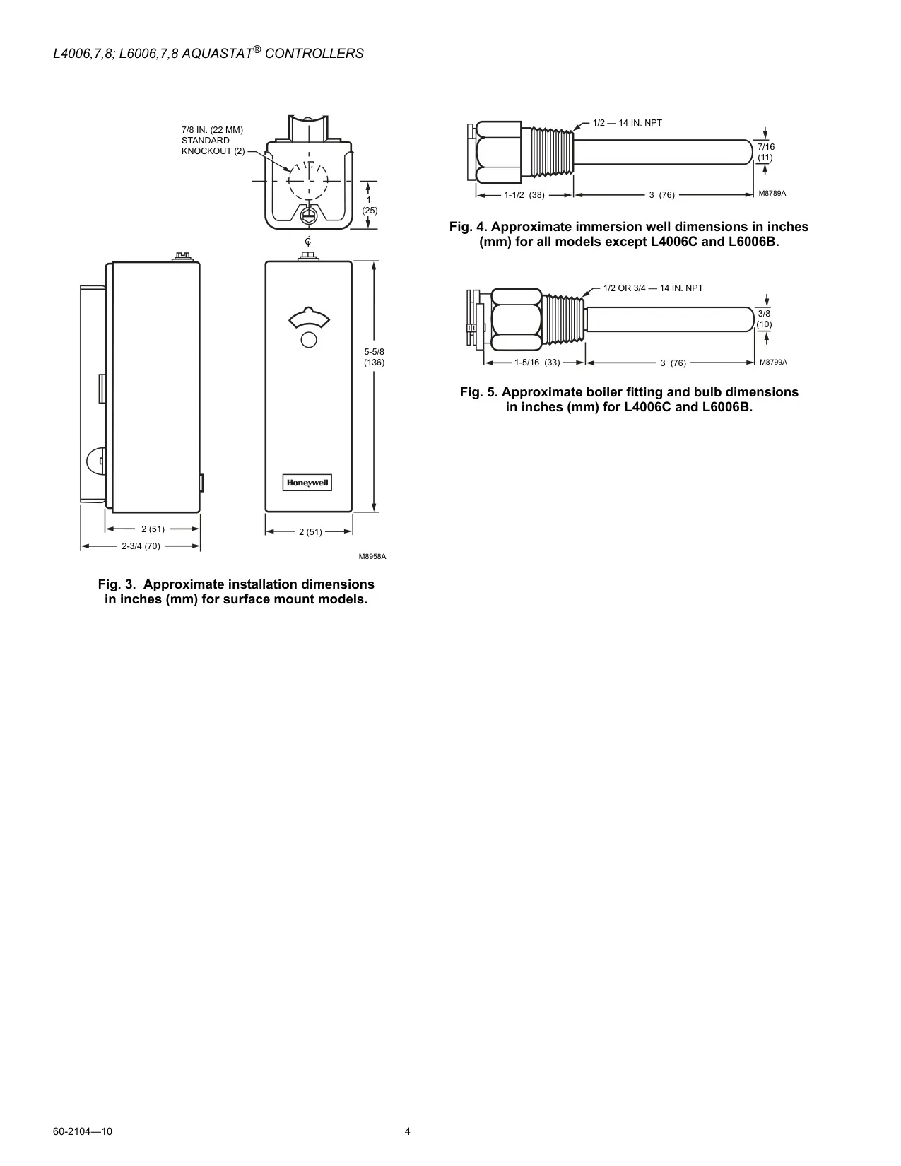
| Well Thread | 1/2 in. or 3/4 in. NPT |
| Insertion Length Option | 3-3/8 in. (86 mm) |
| Insulation Depth | 1-1/2 in. to 3 in. (38 mm to 76 mm) |
| Adjustable Tubing Length | Up to 3 in. (76 mm) on some models |
| Sensing Bulb Material | Copper |
| Sensing Bulb Fill | Liquid (toluene or silicone oil) |
| Sensing Bulb Dimensions | 2-7/8 in. (73 mm) long, 3/8 in. (10 mm) diameter |
| Wiring | Screw terminals (R, B, W) |
| Conduit Knockout | 1/2 in. conduit |
| Maximum Ambient Temperature | 150°F (66°C) |
| Case Height | Approx. 5-5/8 in. (136 mm) |
| Finish | Gray |
| Included Accessories | Tube of heat-conductive compound, mounting adapter for vertical or horizontal mount |
| Optional Accessories | 124904 Well Adapter, 137536A Scale Lock Assembly, 107408 Heat-Conductive Compound (4 oz can) |
| Approvals | UL component recognized (File MP466, Guide MBPR2); CSA (File LR1620, Guide 400-E-O) |
| Installation Instructions Form | 69-0235-5 |
Honeywell Aquastat L6006a Details
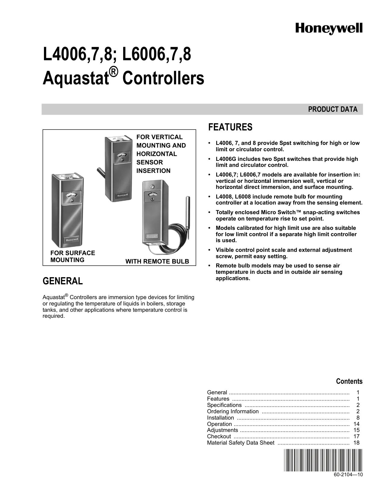
The Honeywell L6006A Aquastat Controller responds to water temperature changes in hydronic heating systems. As a SUPER TRADELINE model, it is made to replace a wide range of Honeywell and competitive controls. It comes in a package with a cross reference label and special instructions. One SPDT switch lets a single device do high limit, low limit or circulator control, depending on which terminals the installer uses.
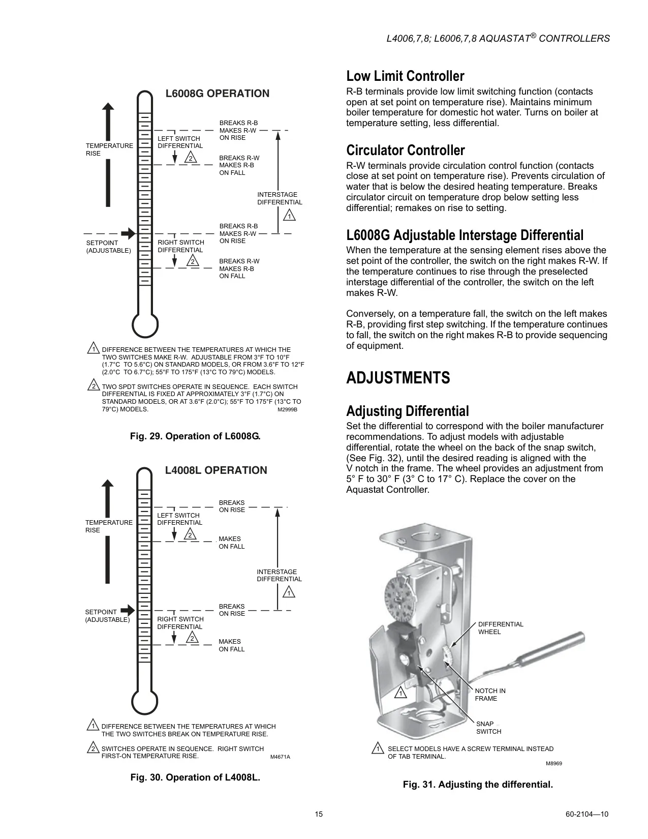
The switching works like this. When water temperature drops to the dial setting minus the differential, contacts R to B make and contacts R to W break, which stops the circulator. When temperature rises back to the dial setting, R-B breaks and R-W makes. Used as a high limit, the control shuts off the burner above the setpoint. Used as a low limit, it keeps a minimum boiler temperature for domestic hot water, such as a tankless coil.
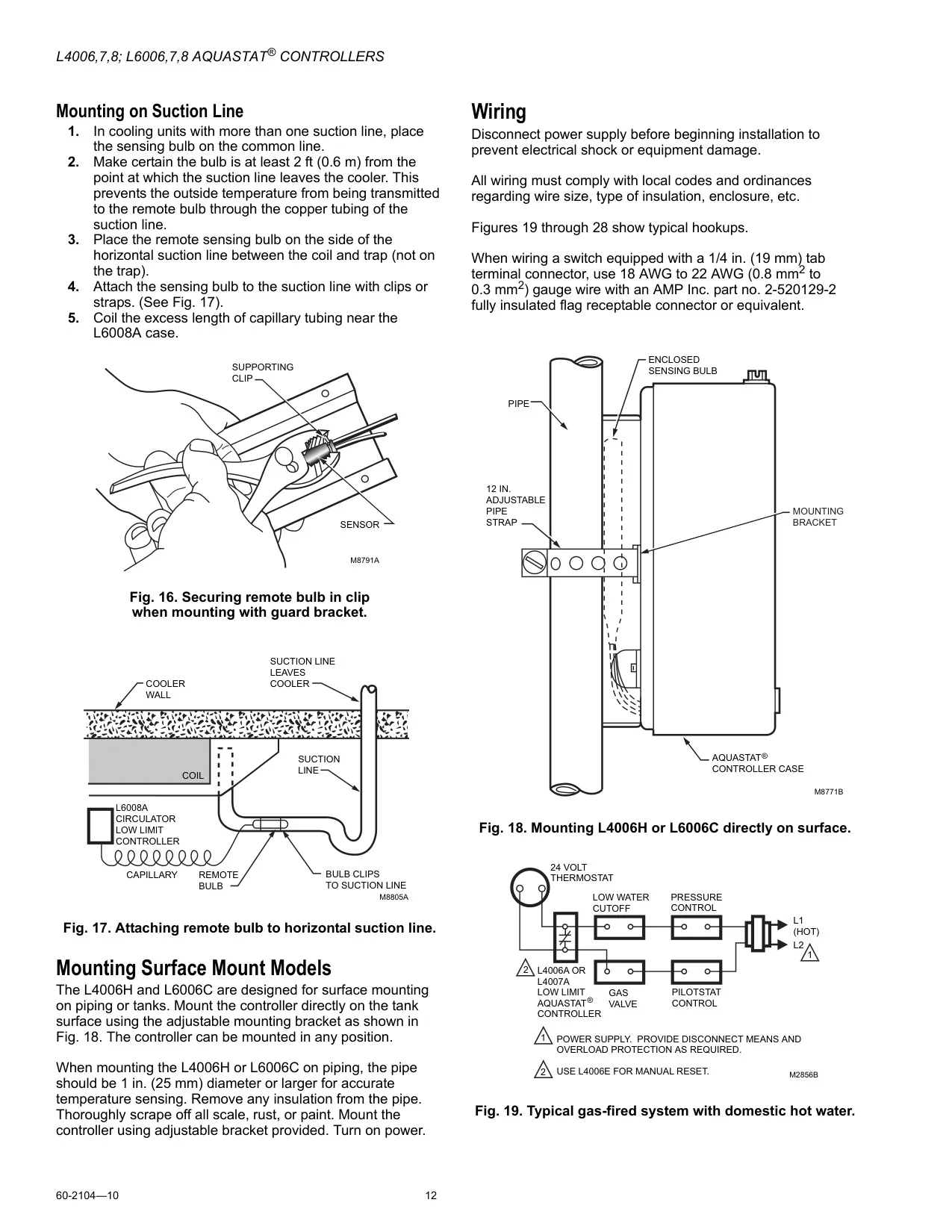
In circulator mode, the controller stops water that is not hot enough from circulating. Honeywell's wiring diagrams show two common setups. In the first, the L6006 handles low limit and circulator control in an oil-fired hydronic system with a Protectorelay control and a switching relay. In the second, it works with an L8148A Aquastat Relay. In that setup, you remove the L1-3 jumper when using circulator low limit control.
Installation should be done by a trained, experienced service technician with the power off. If the old immersion well looks suitable and fits the adapter clamp, you can keep it. Otherwise, drain the system below the boiler tapping and install a new well. Use a reduction fitting and thread seal compound on larger tappings. Do not use the case to tighten the well, because that puts force on the controller.
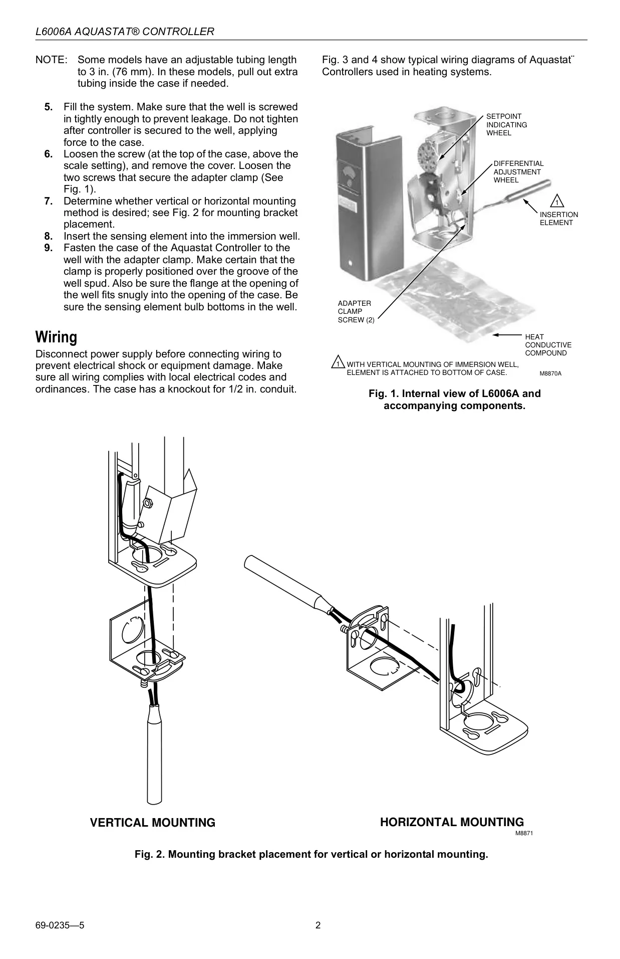
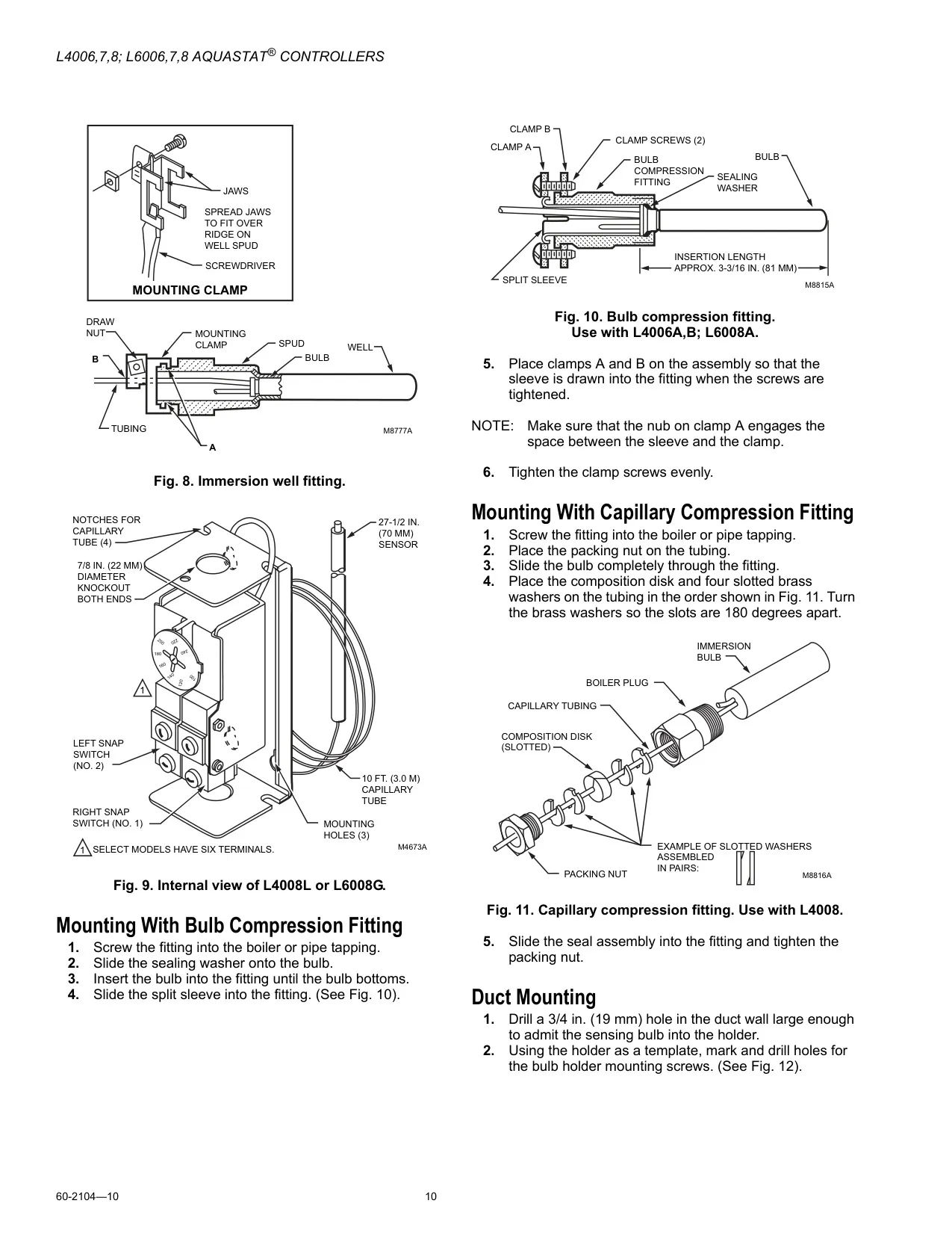
To mount the unit, remove the cover, loosen the two adapter clamp screws and place the mounting bracket for vertical or horizontal mounting. With vertical mounting, the element attaches to the bottom of the case. Insert the bulb until it touches the bottom of the well. Set the clamp over the groove in the well spud and make sure the well flange fits snugly into the case opening. If the well was made for a larger bulb, use the included heat-conductive compound.
Product data also warns that the controller is meant only for systems with a pressure relief valve. The terminals accept copper wire only. Avoid sharp bends in the capillary tubing. A break in the tubing loses the fill, and the limit contacts then stay made. Do not replace an immersion-type Aquastat with a strap-on model.
To set the differential, turn the wheel on the back of the snap switch until the reading you want lines up with the V notch in the frame. To set the control point, turn the slotted screw under the cover window. To move the factory-set stop, push a bent paper clip into the small hole in the dial. At checkout, run the system through several cycles to confirm the limit and circulator functions work.
Frequently Asked Questions (FAQs)
Can't find the answer you need? Here are some frequently asked questions about the Honeywell Aquastat L6006a Hydronic Controller, and we answer them below.