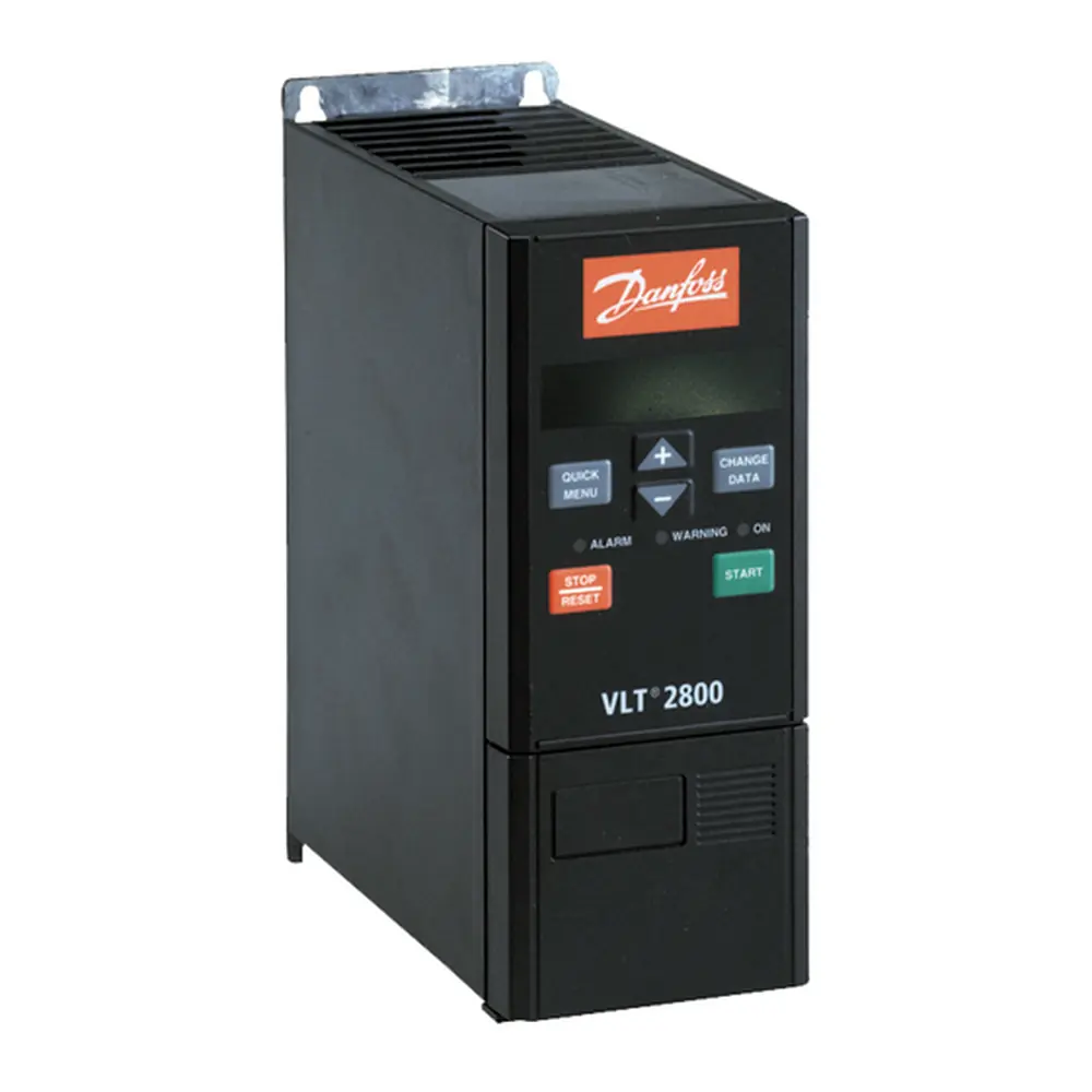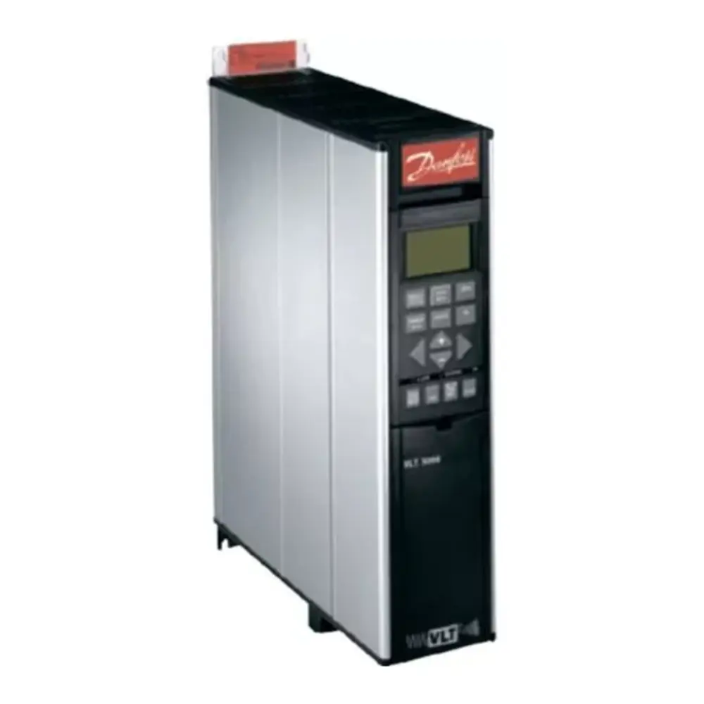
Danfoss FC-302 Variable Frequency Drive Instruction Manual
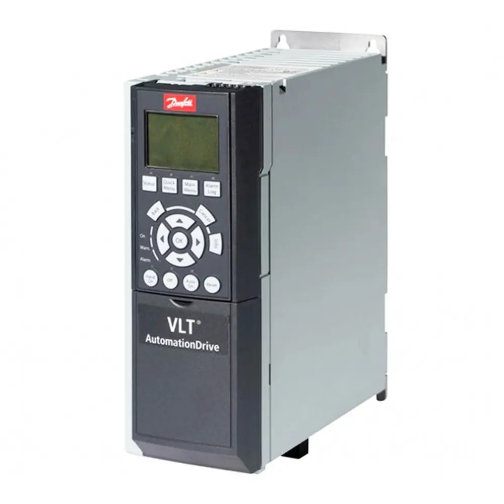
Danfoss FC-302 Variable Frequency Drive
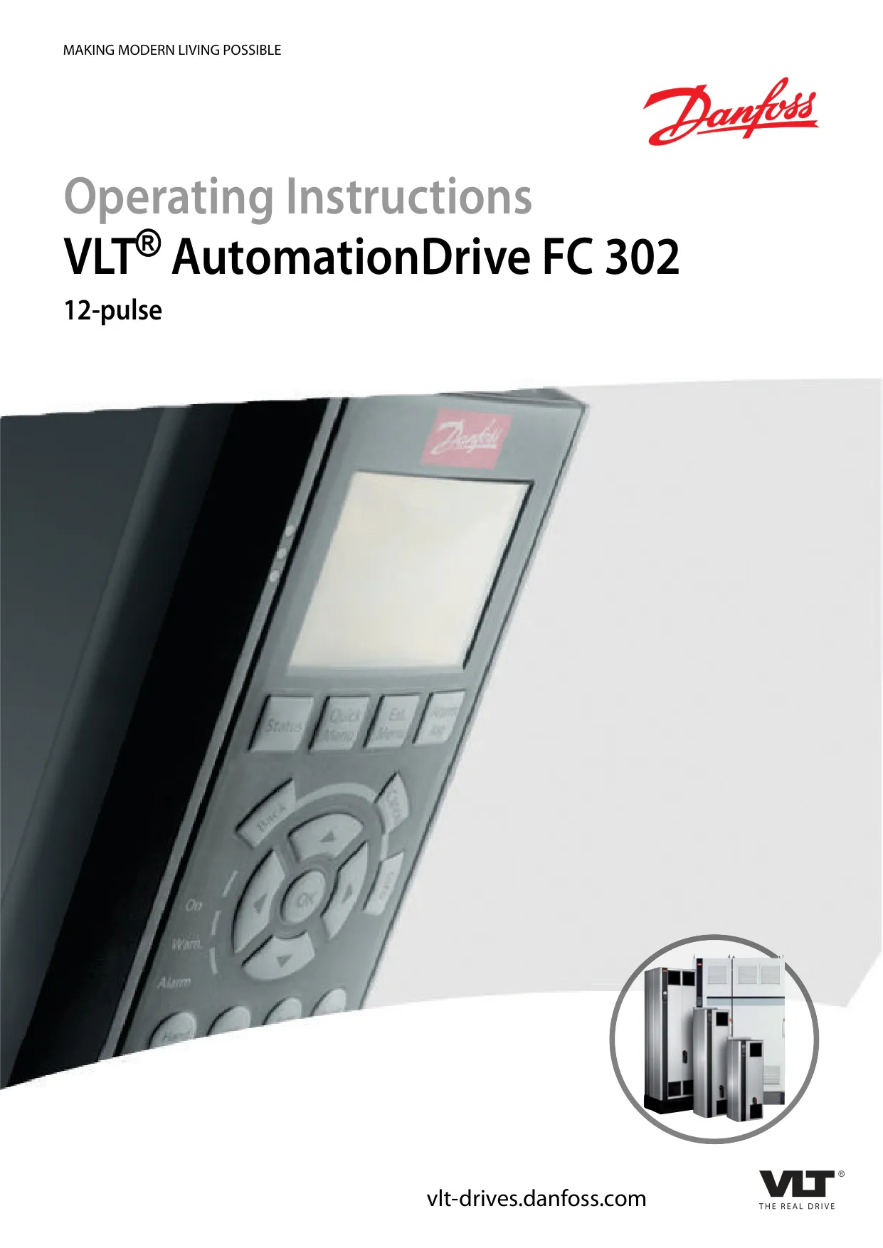

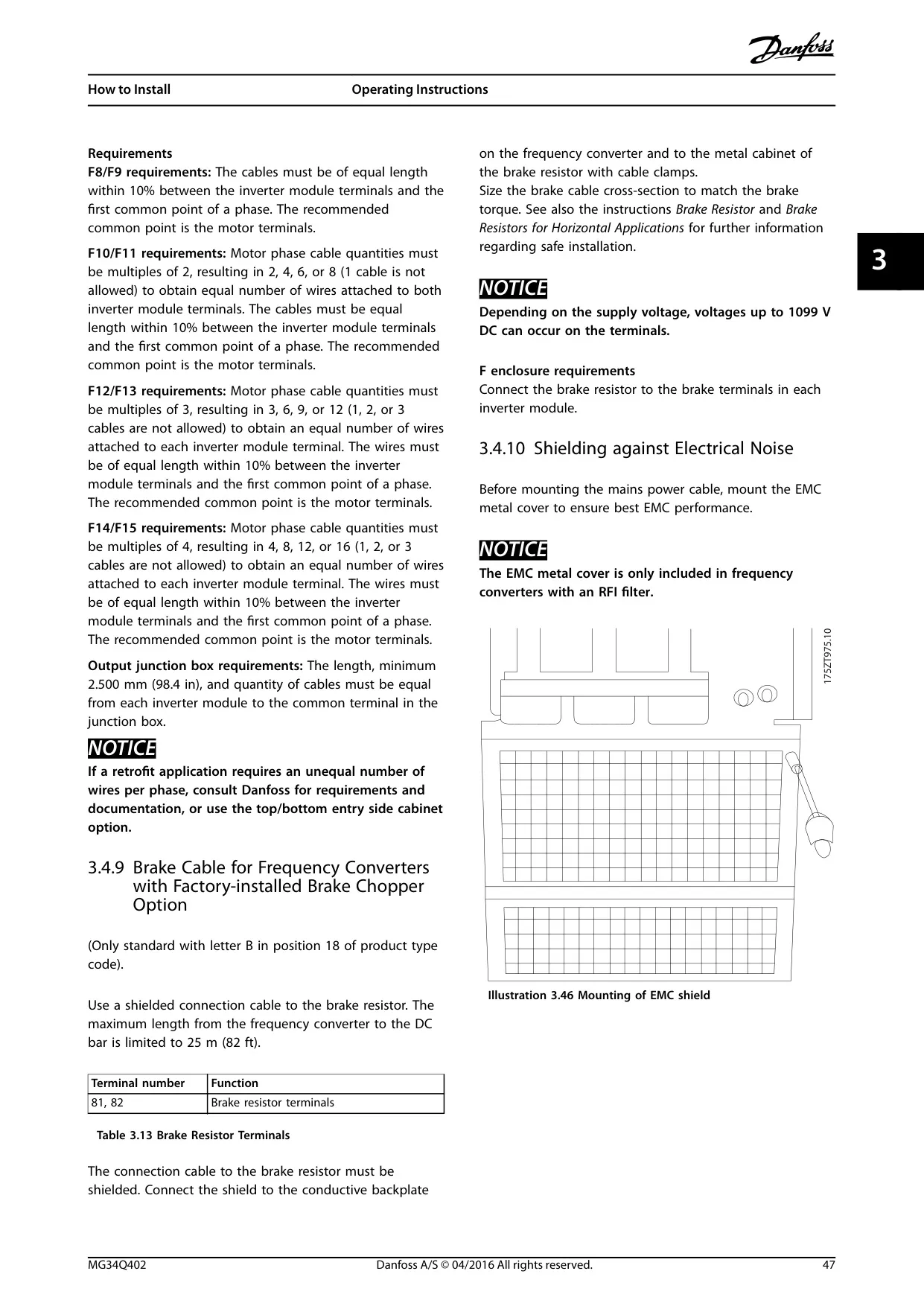
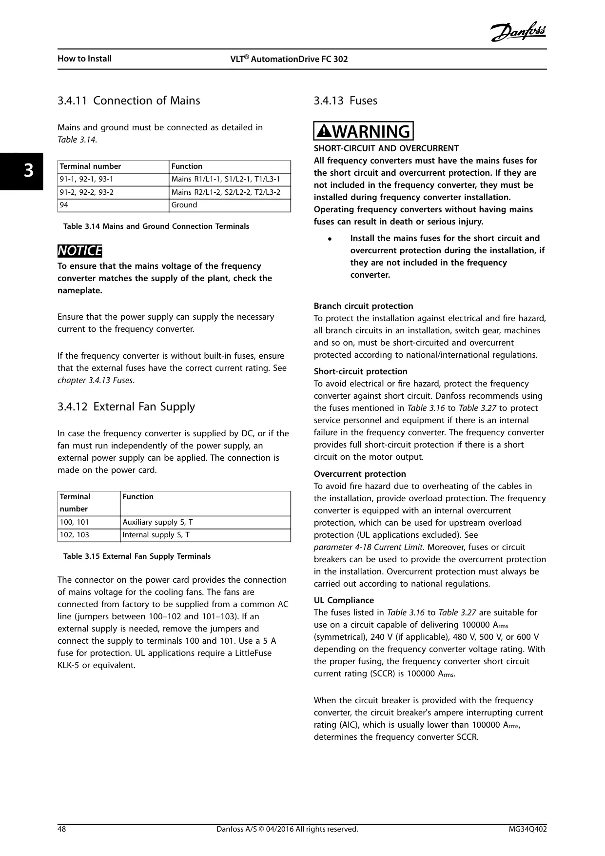
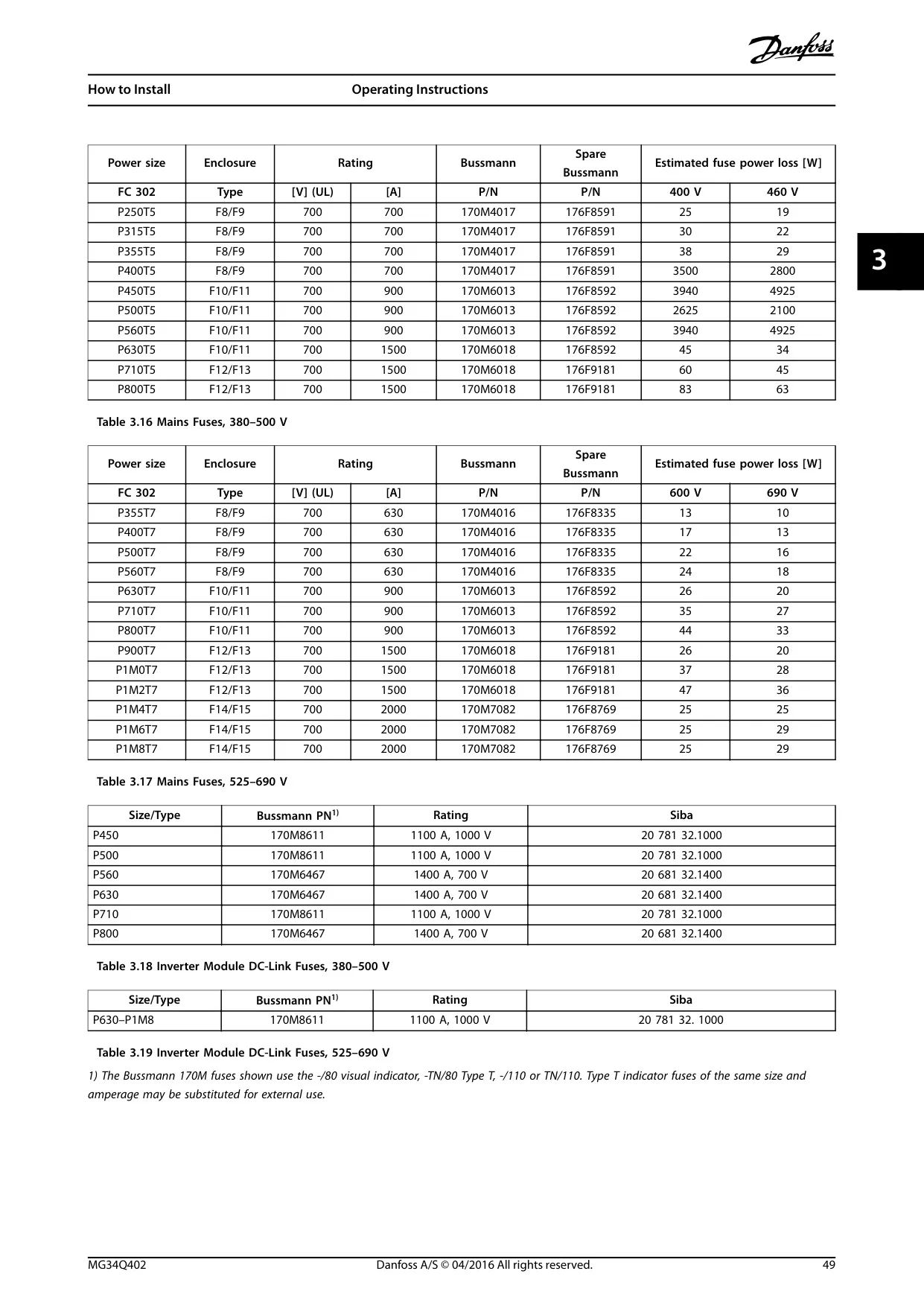
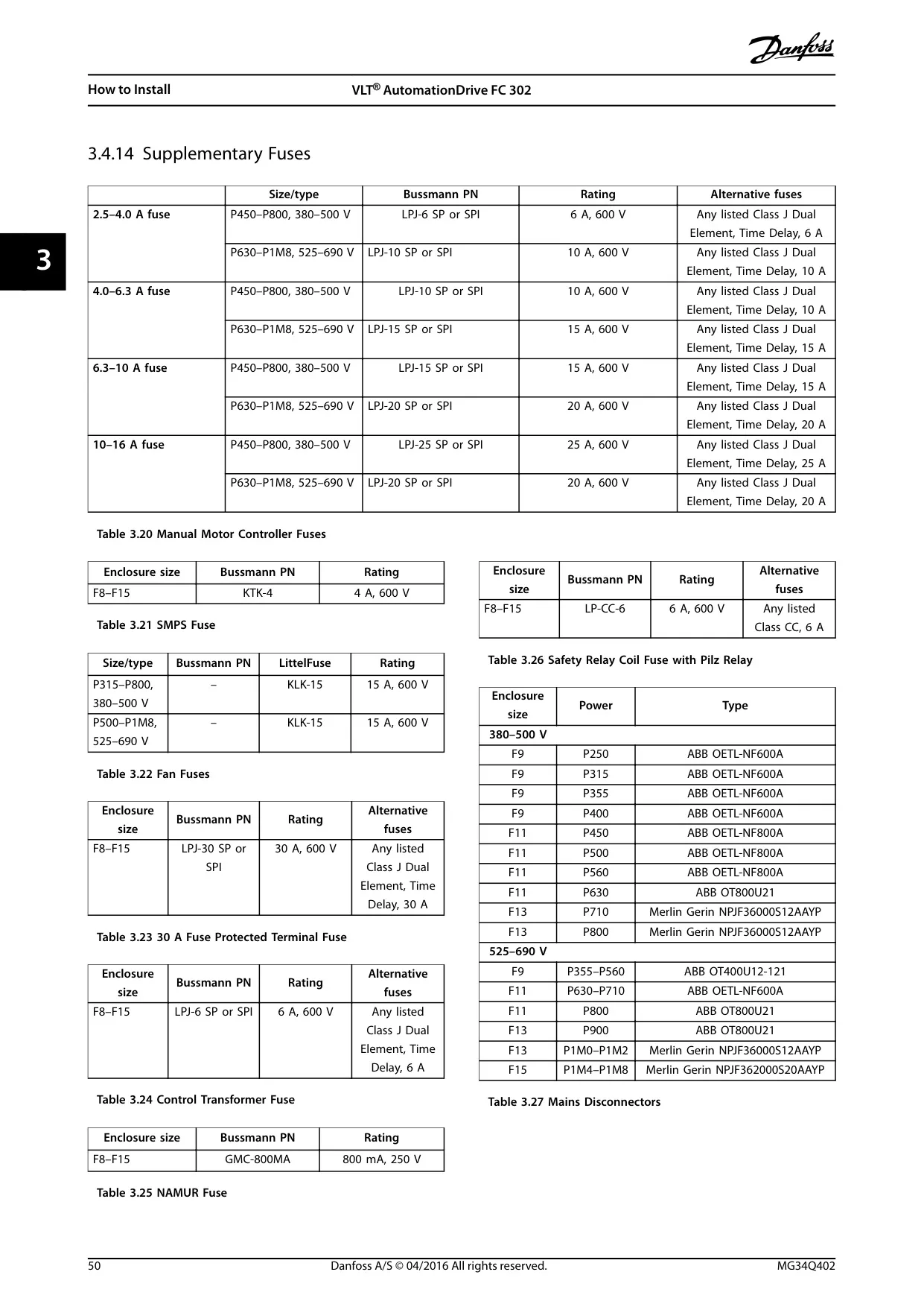
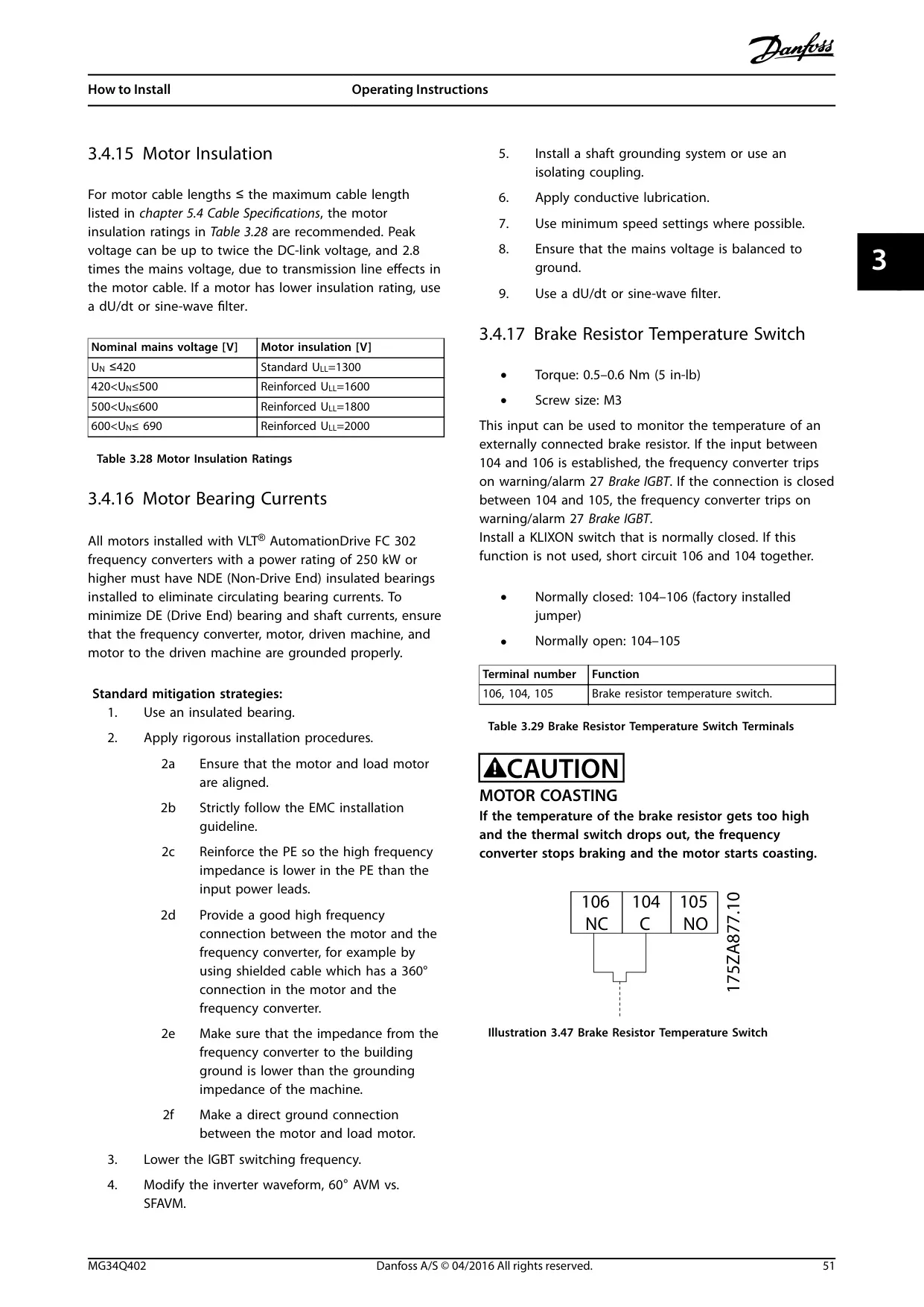
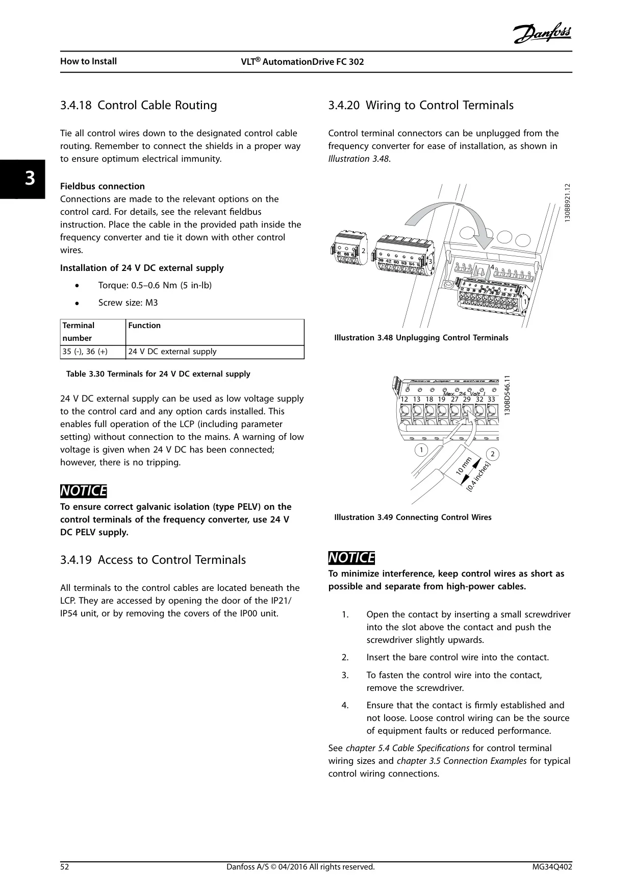
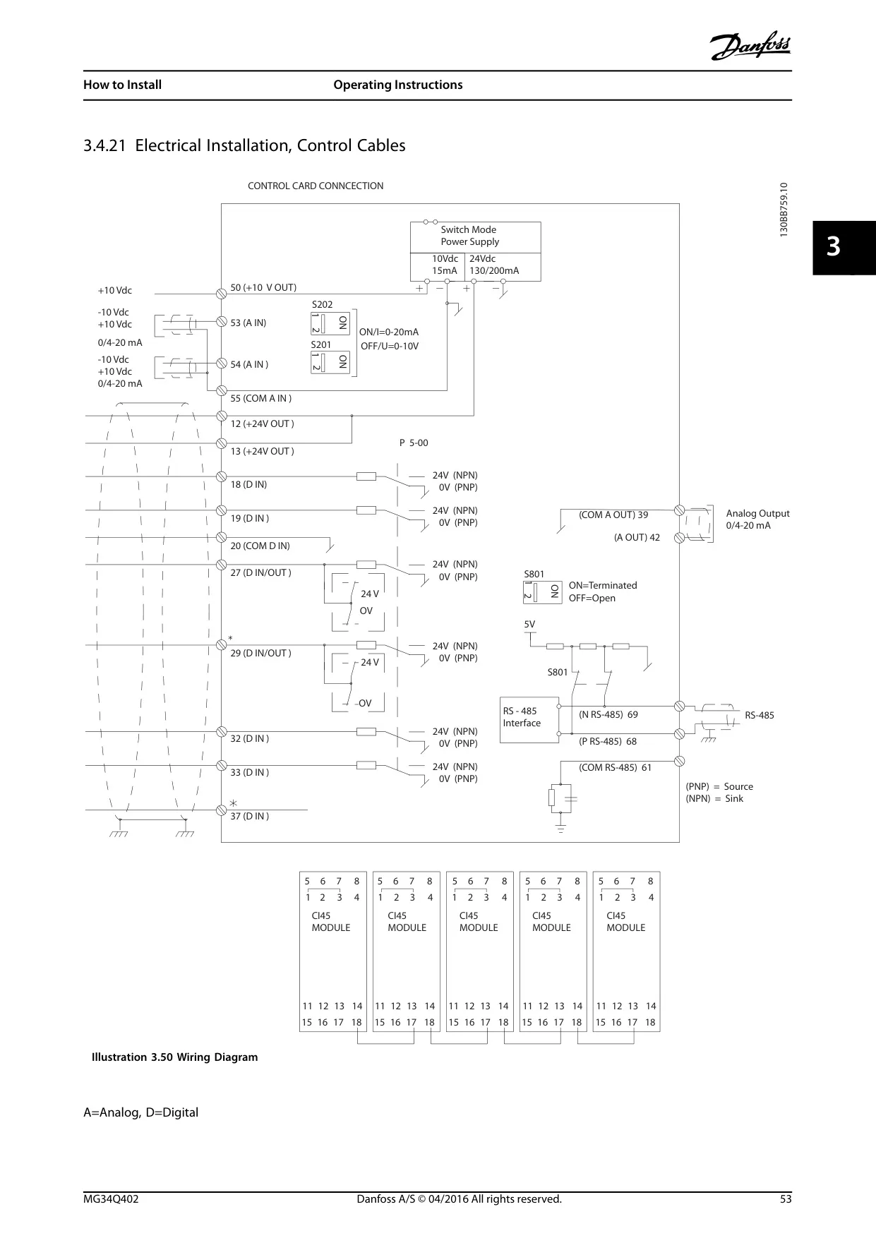
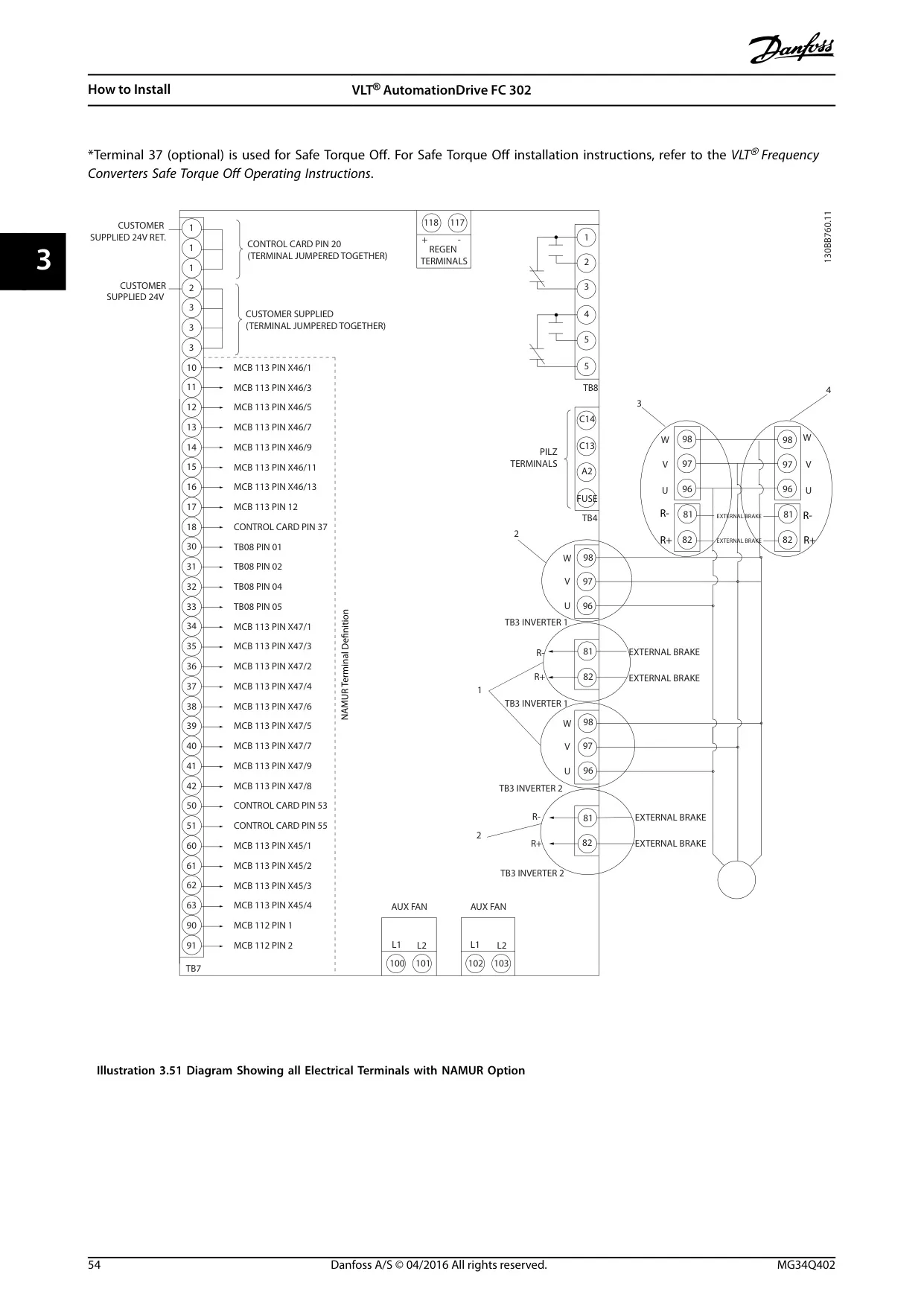
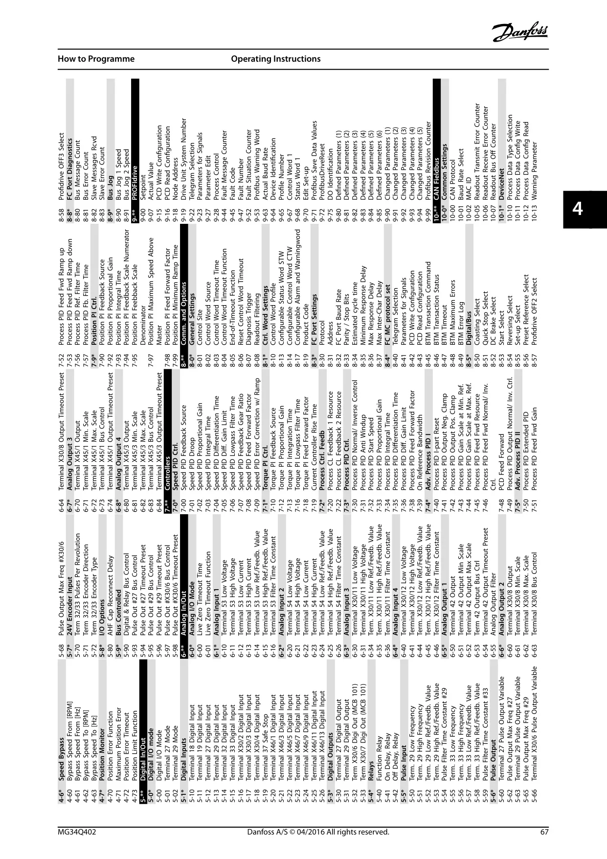
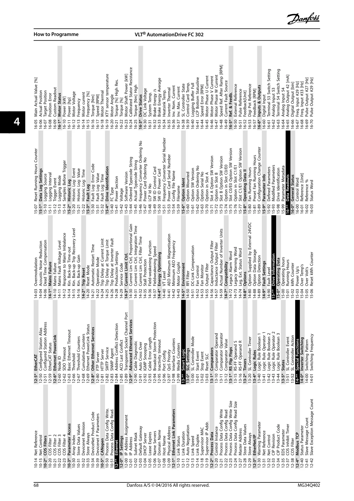
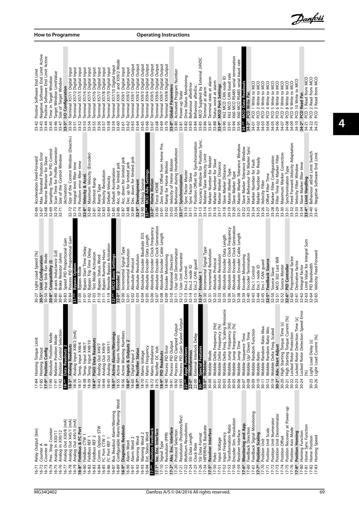
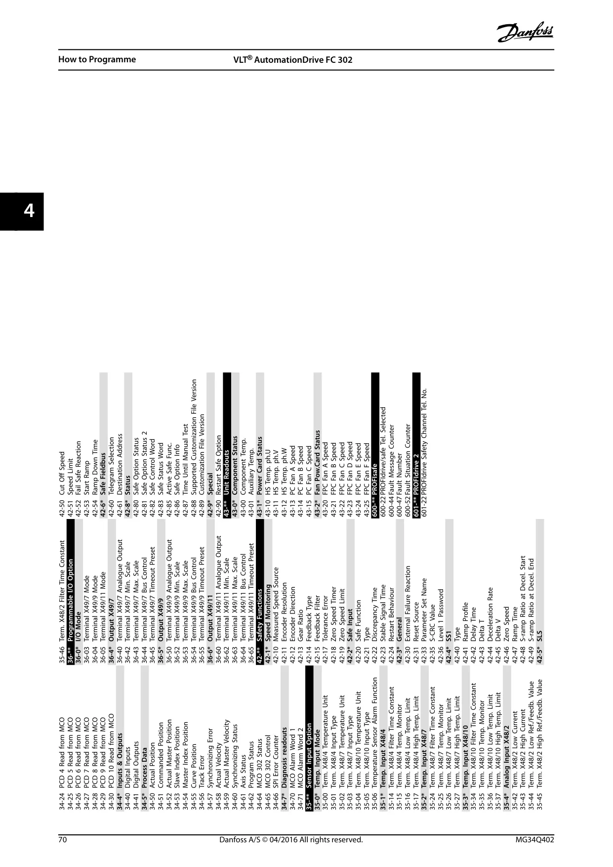
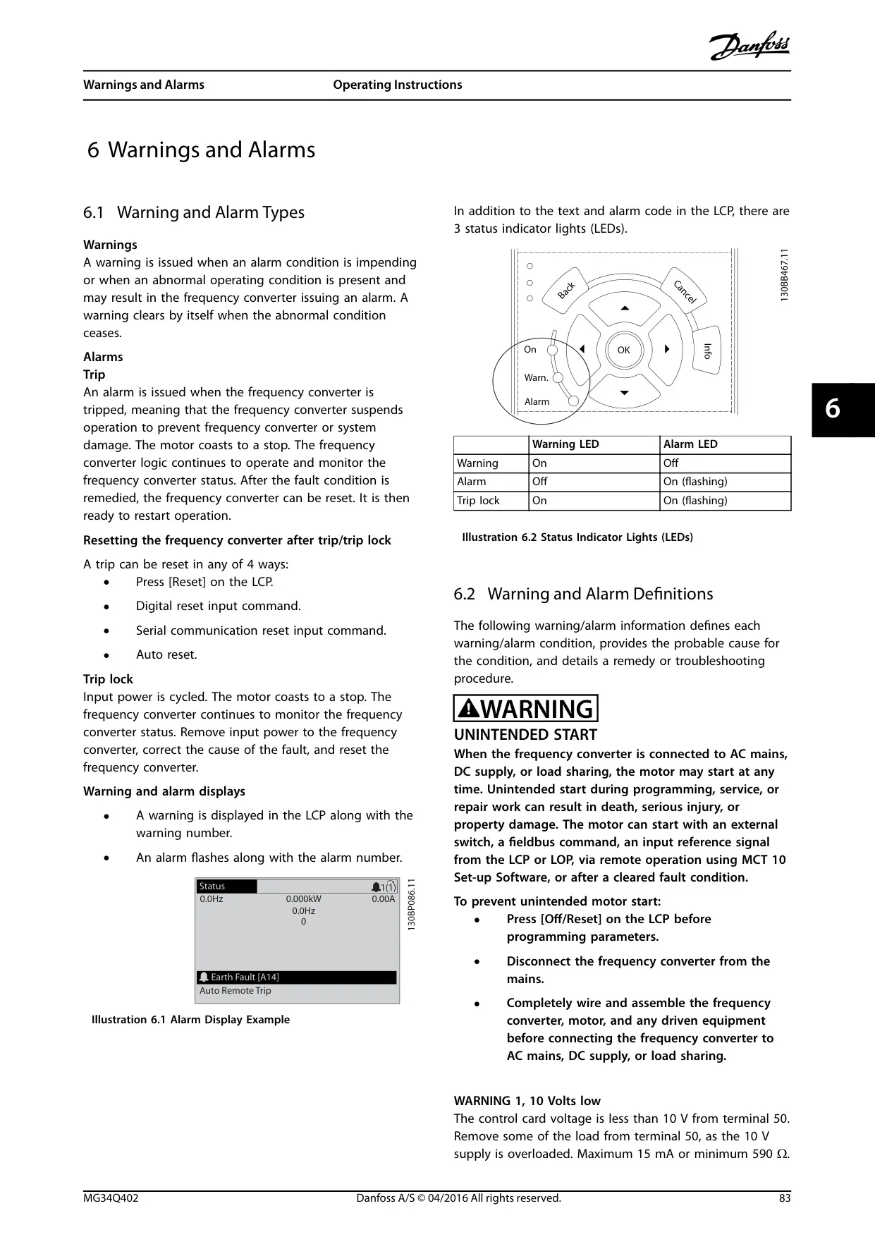
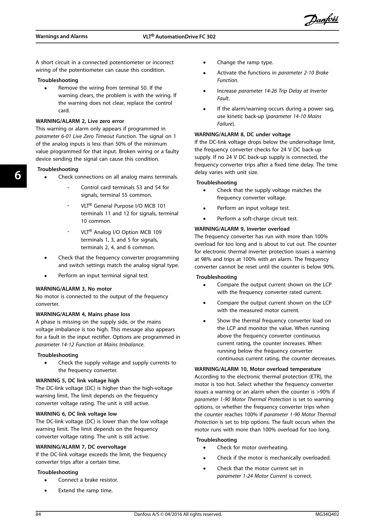
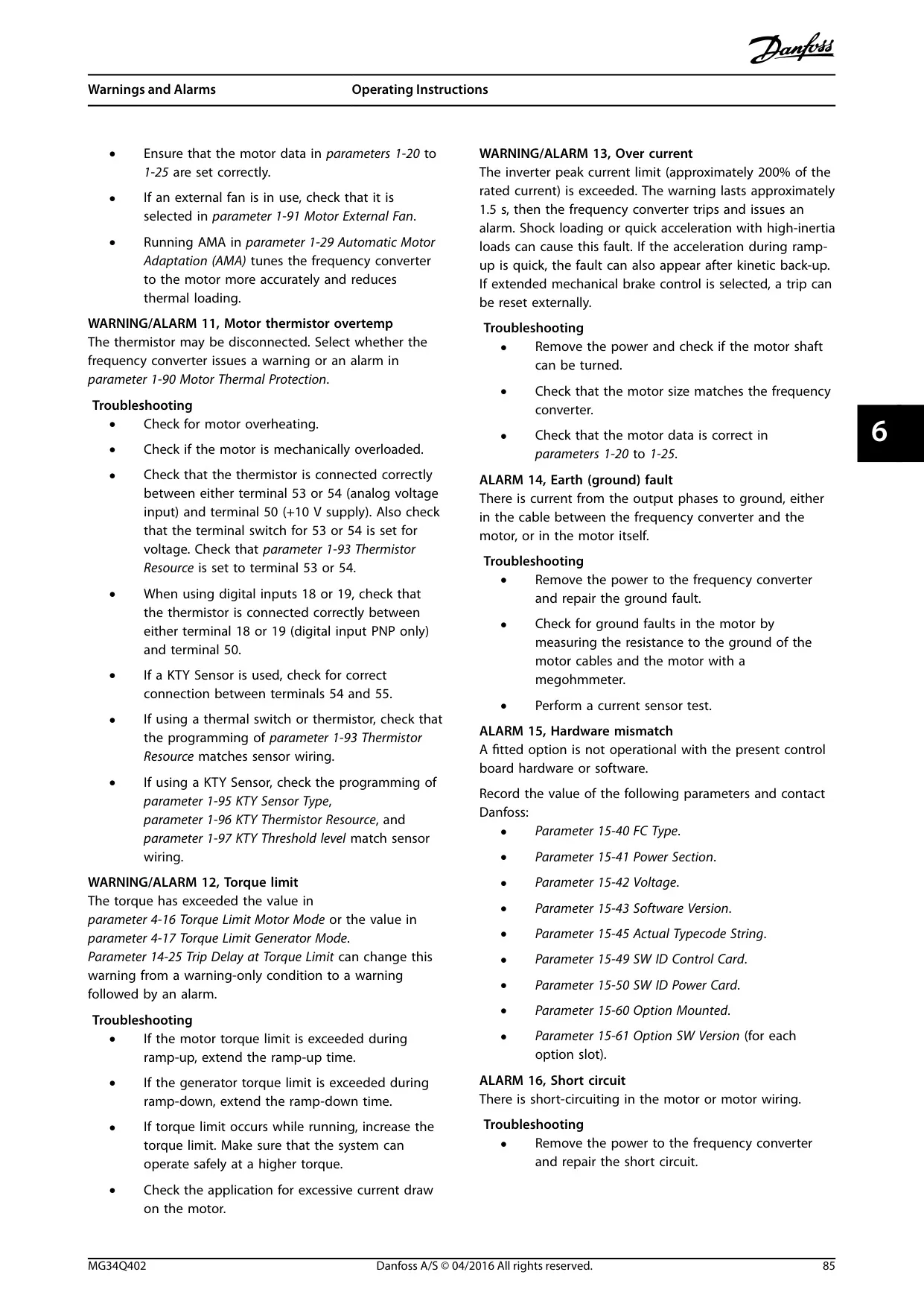
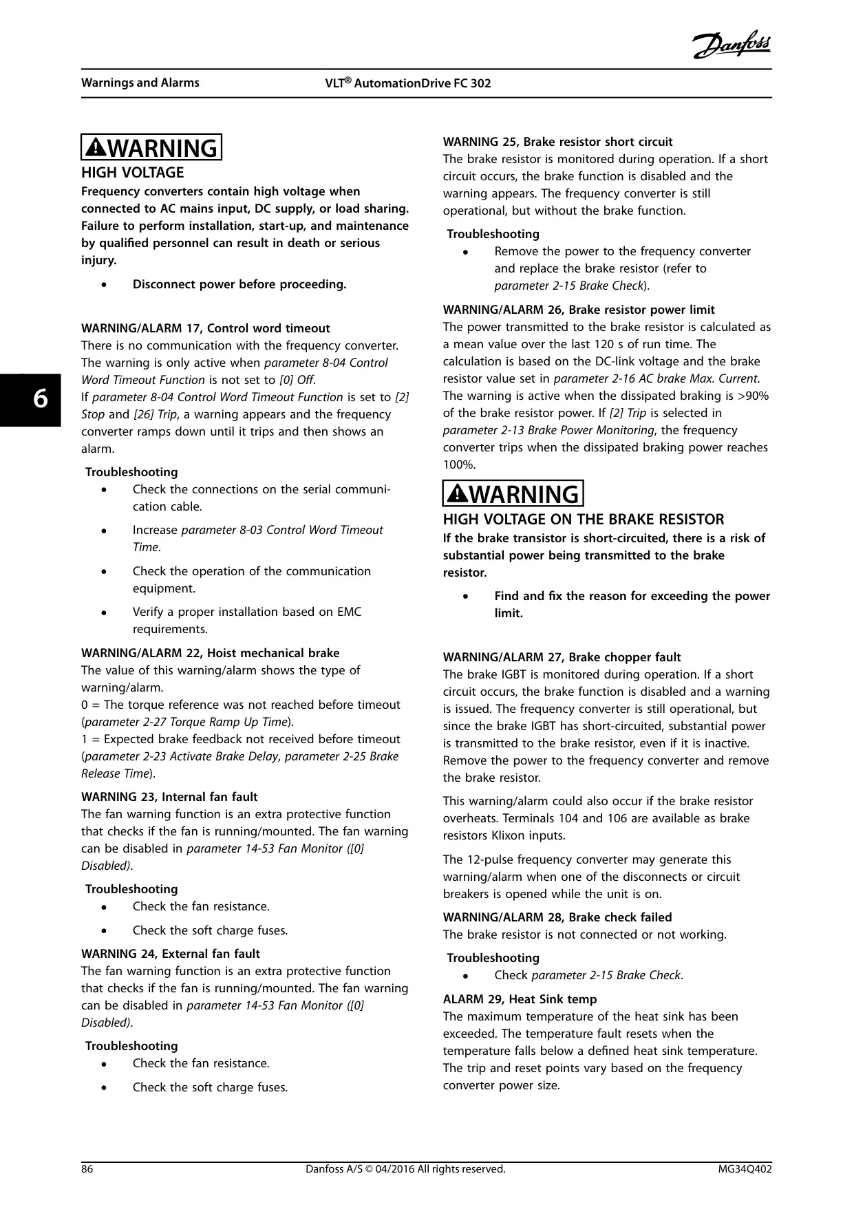
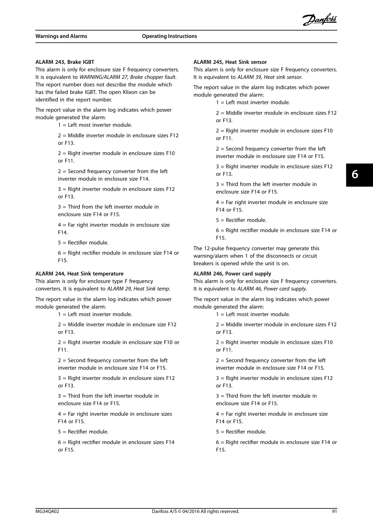
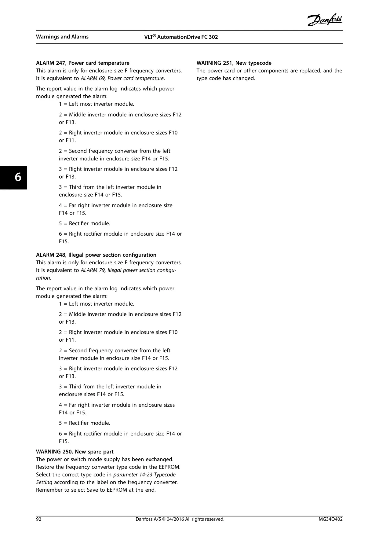
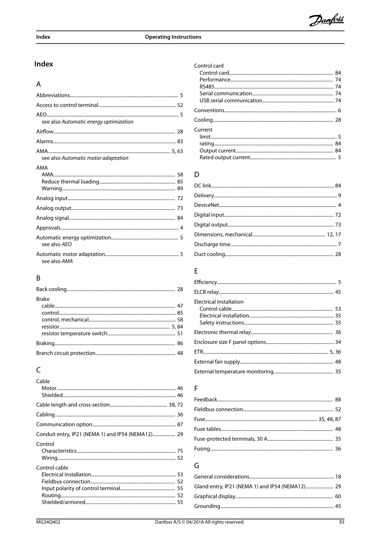
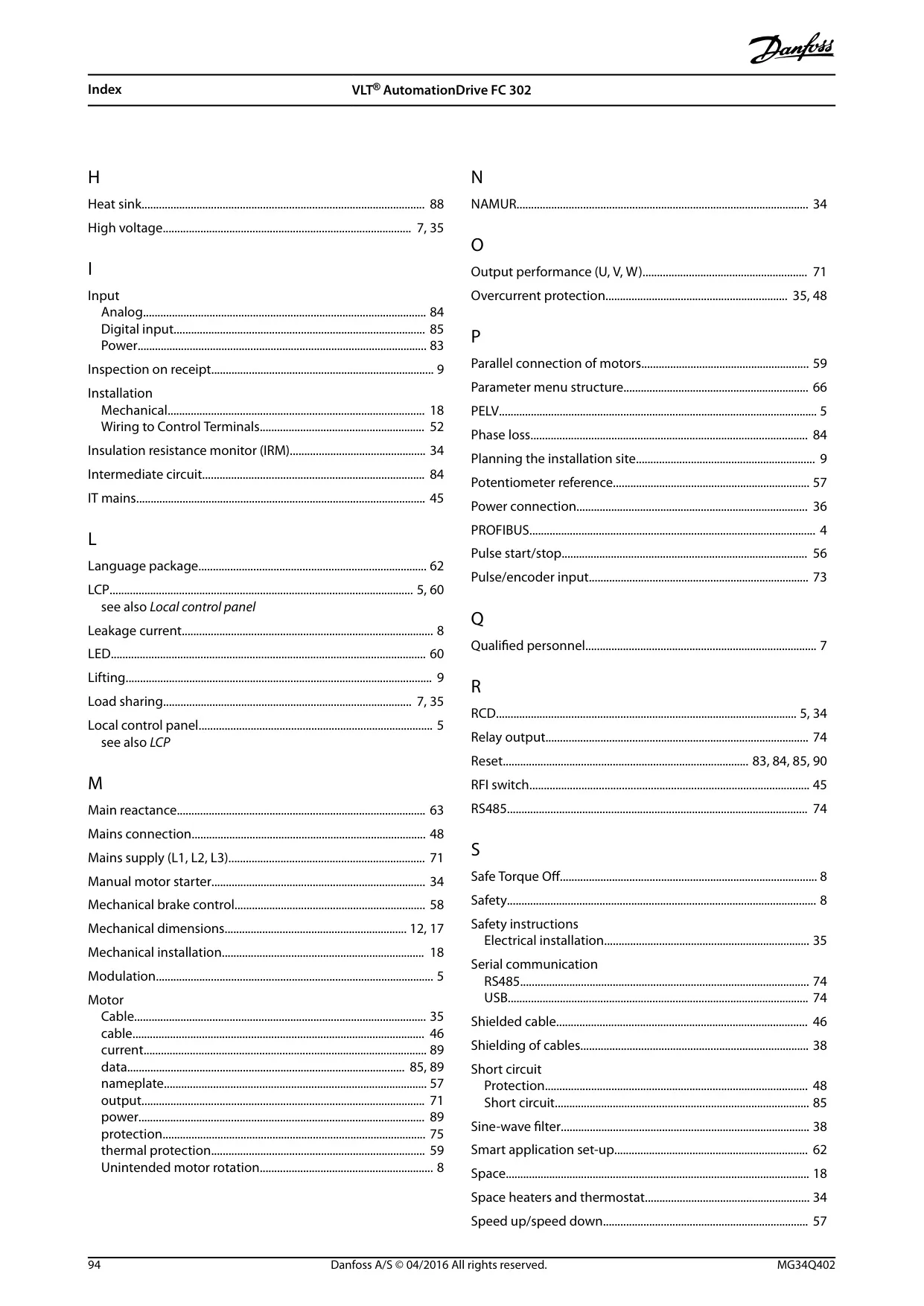



Danfoss FC-302 Variable Frequency Drive
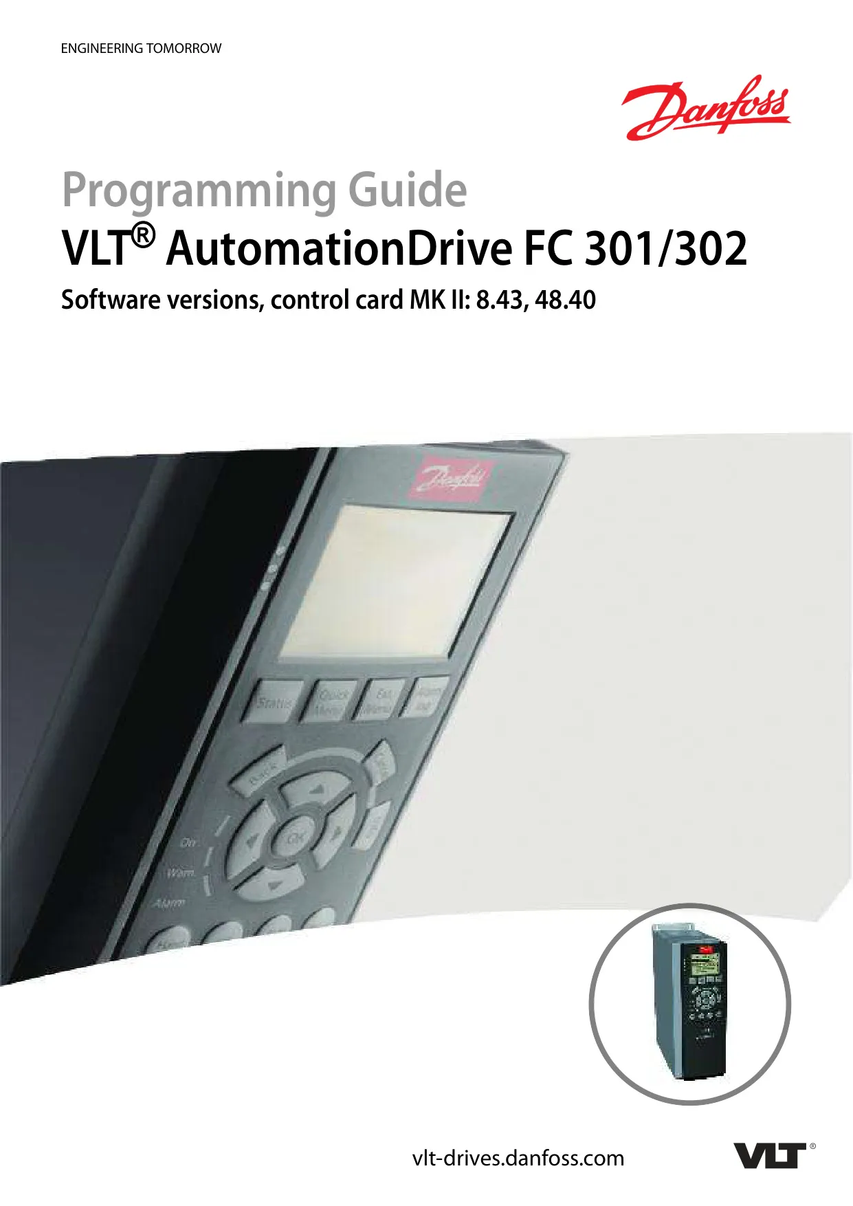

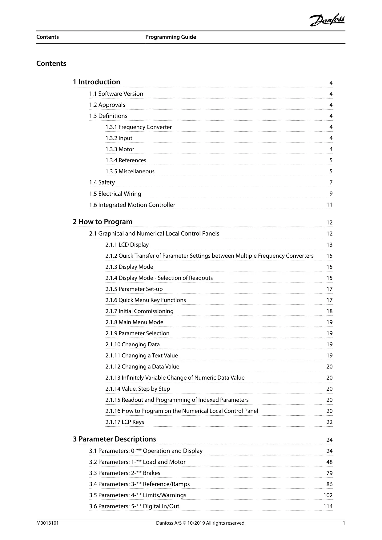
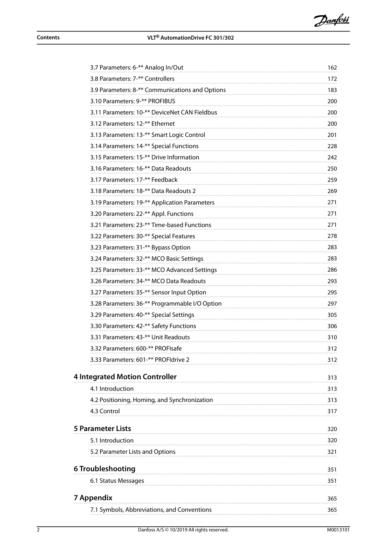
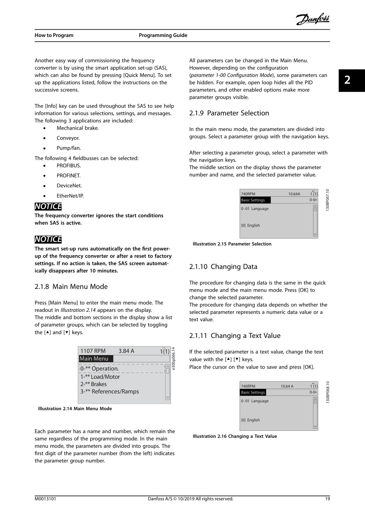
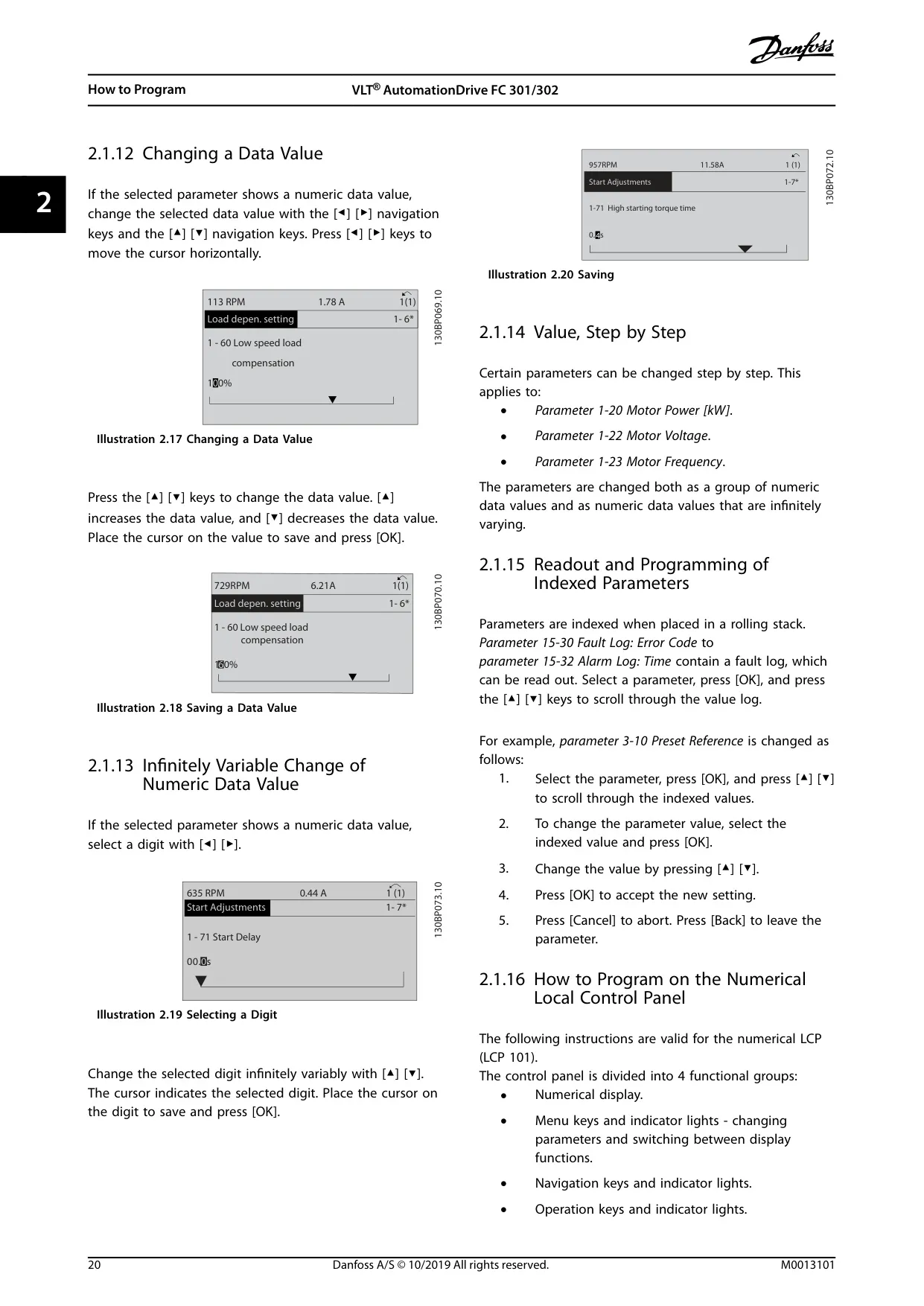
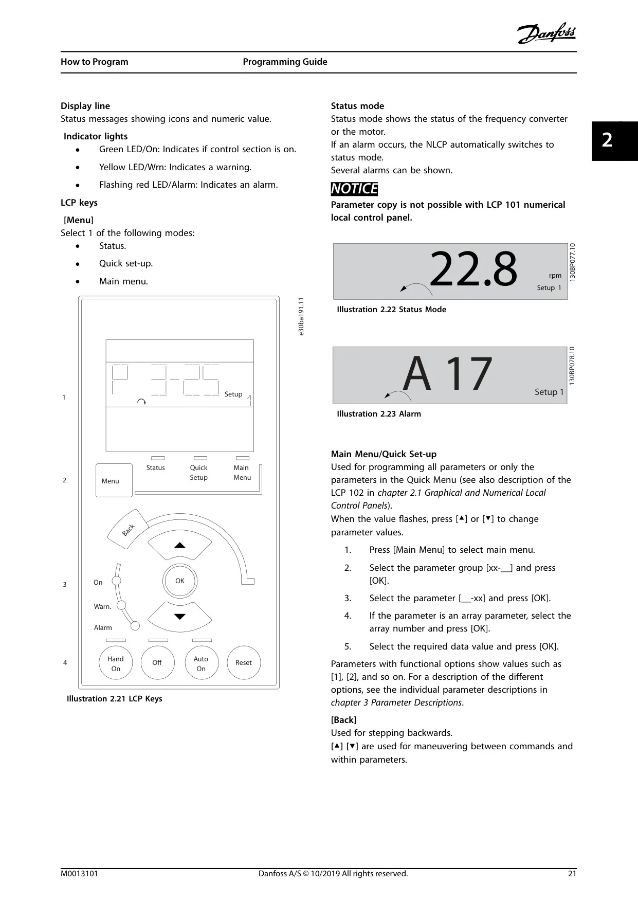
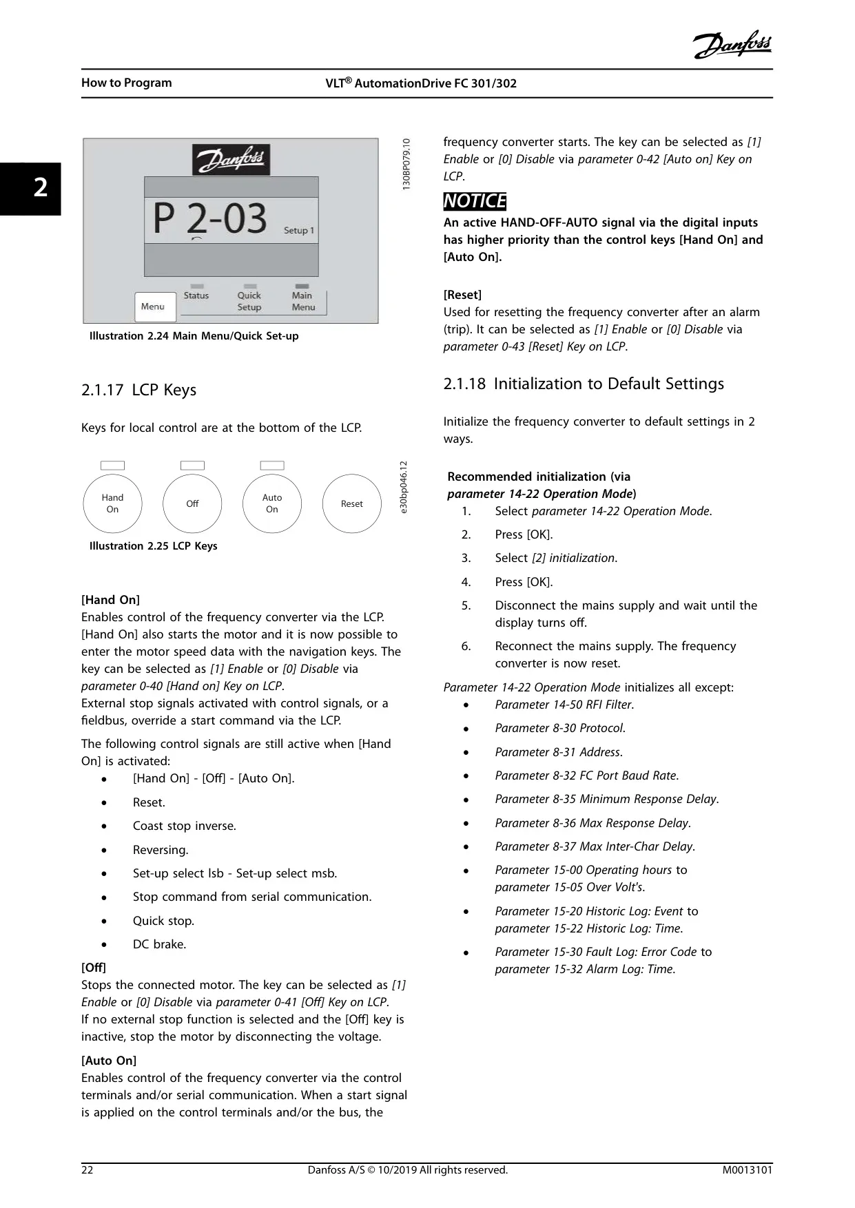
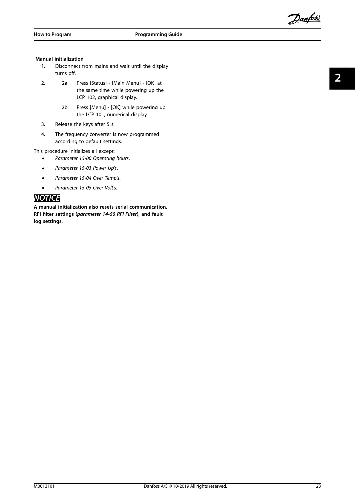
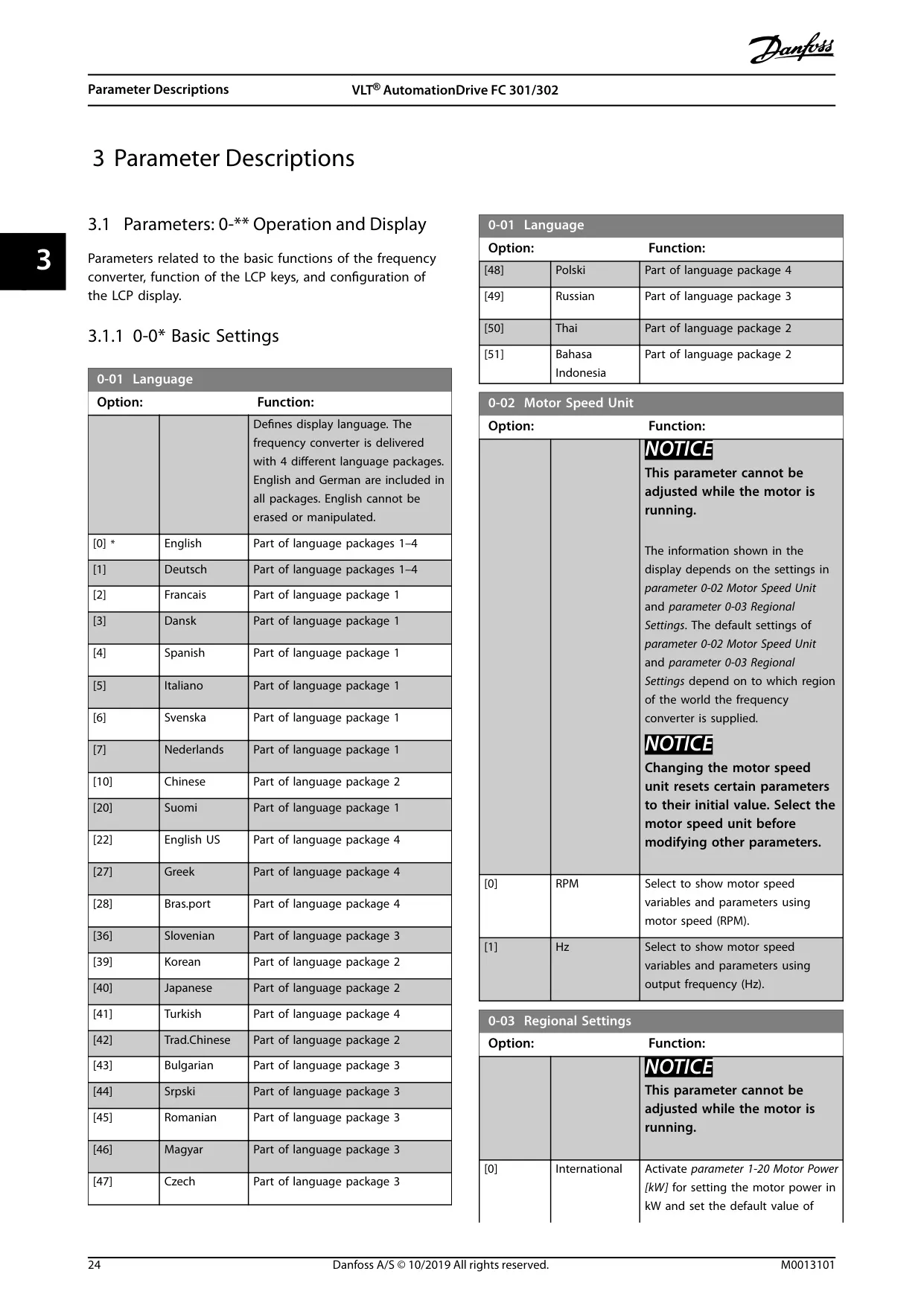
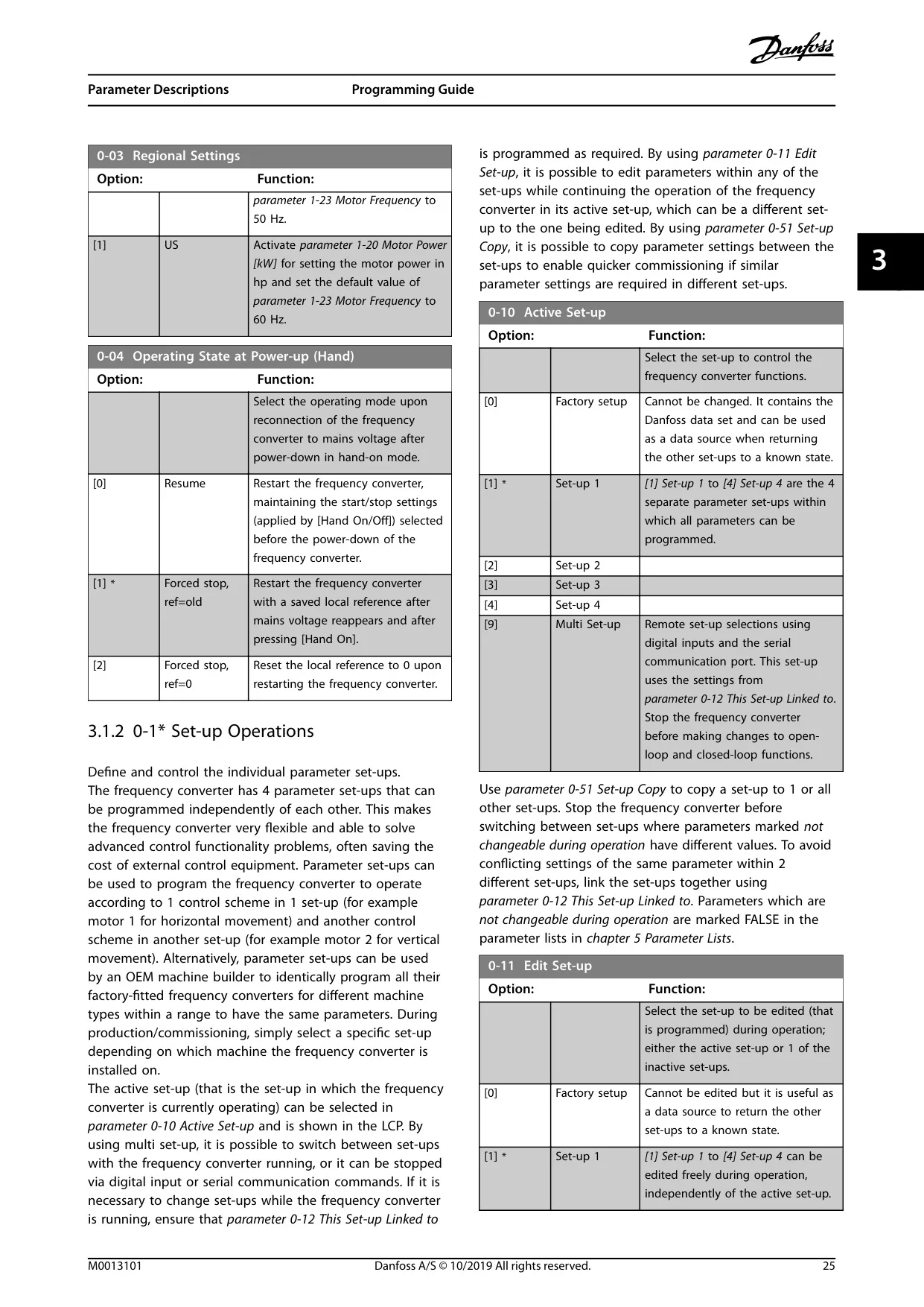
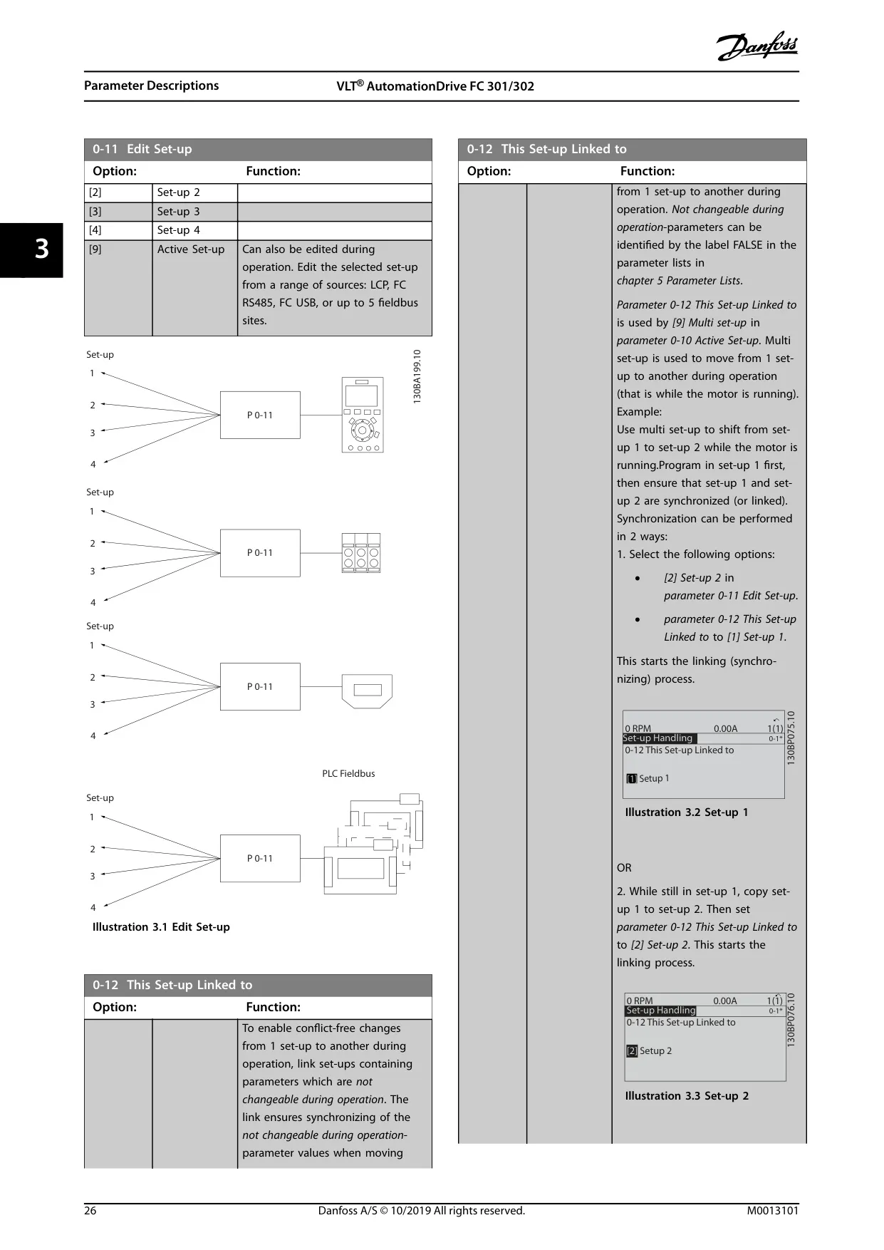
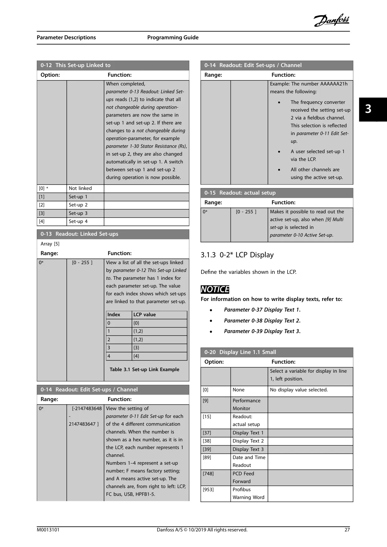
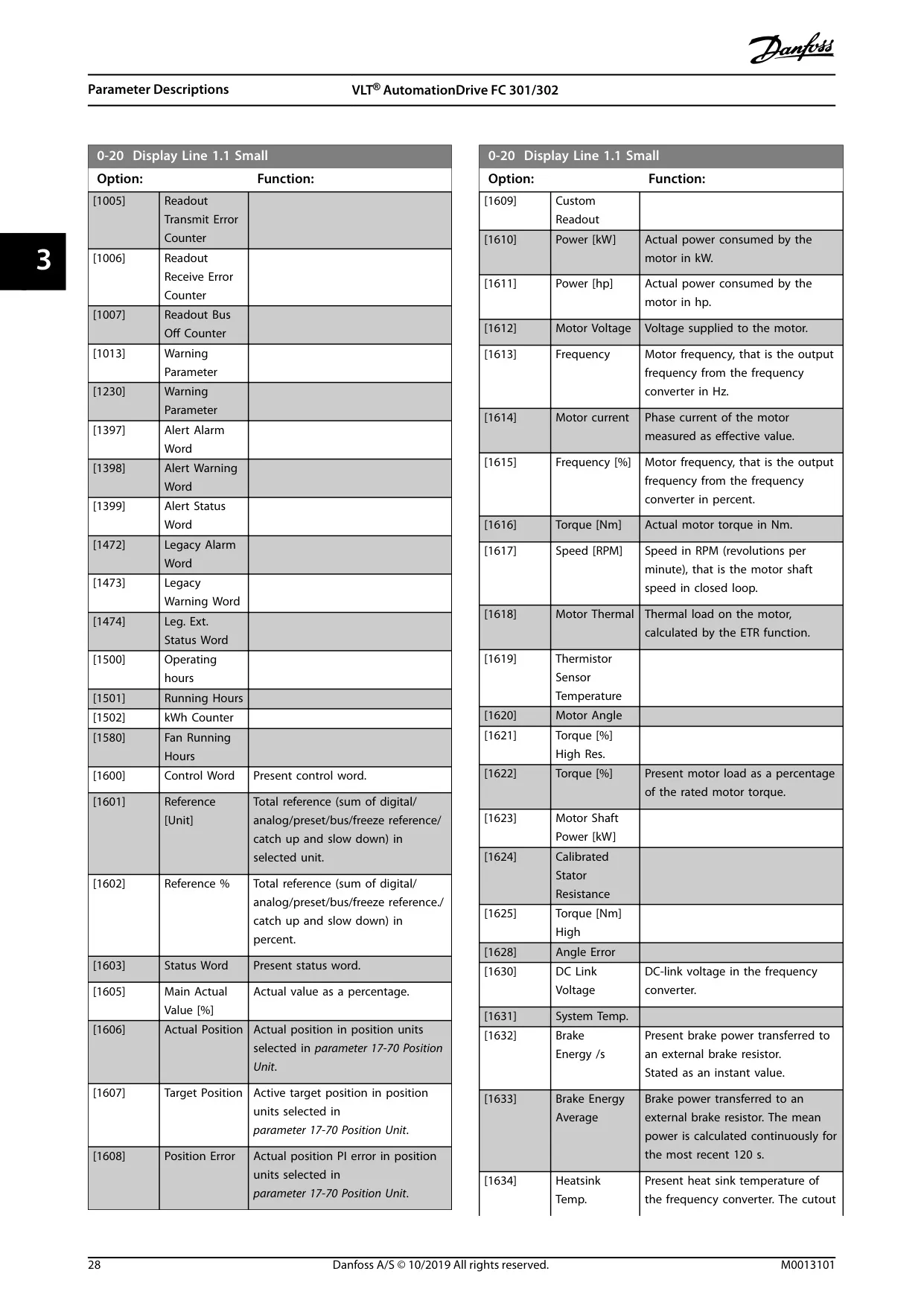
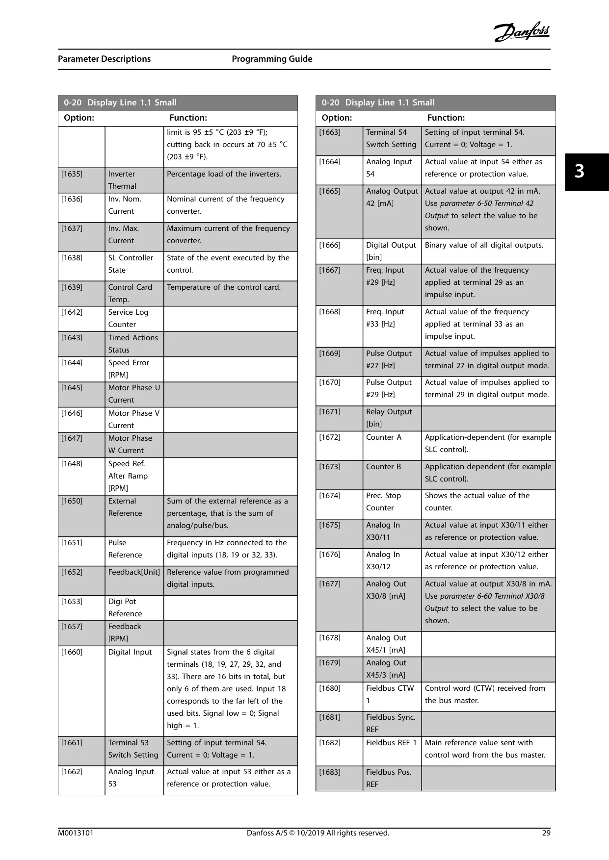
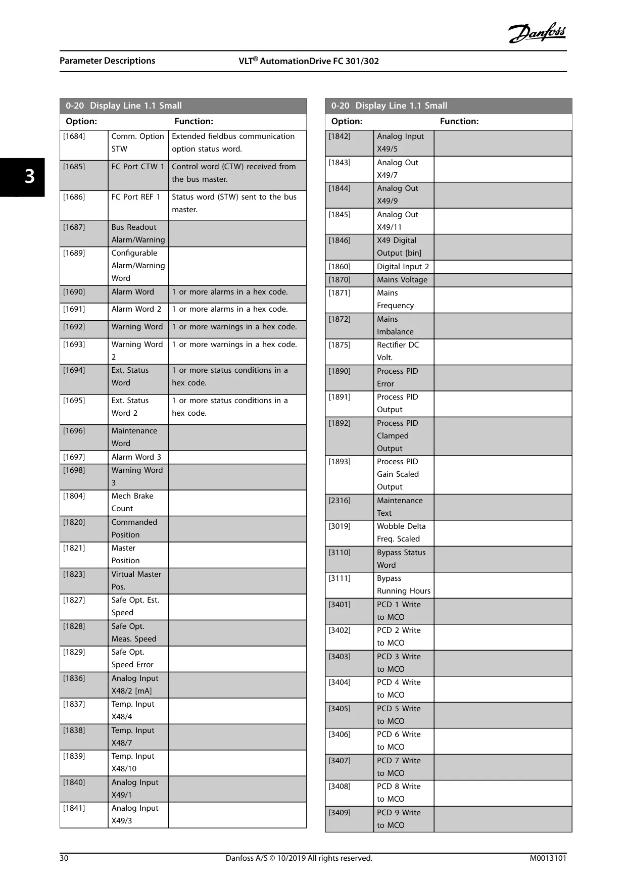
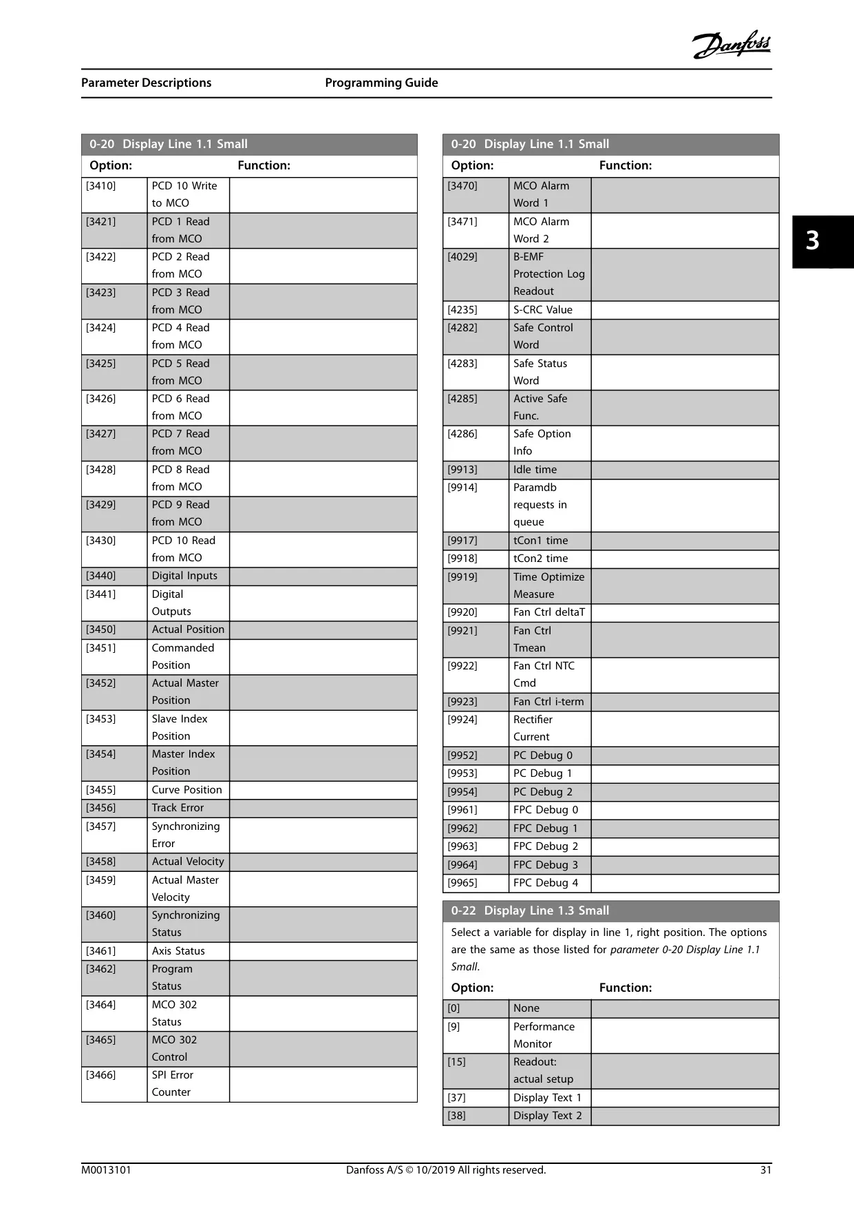
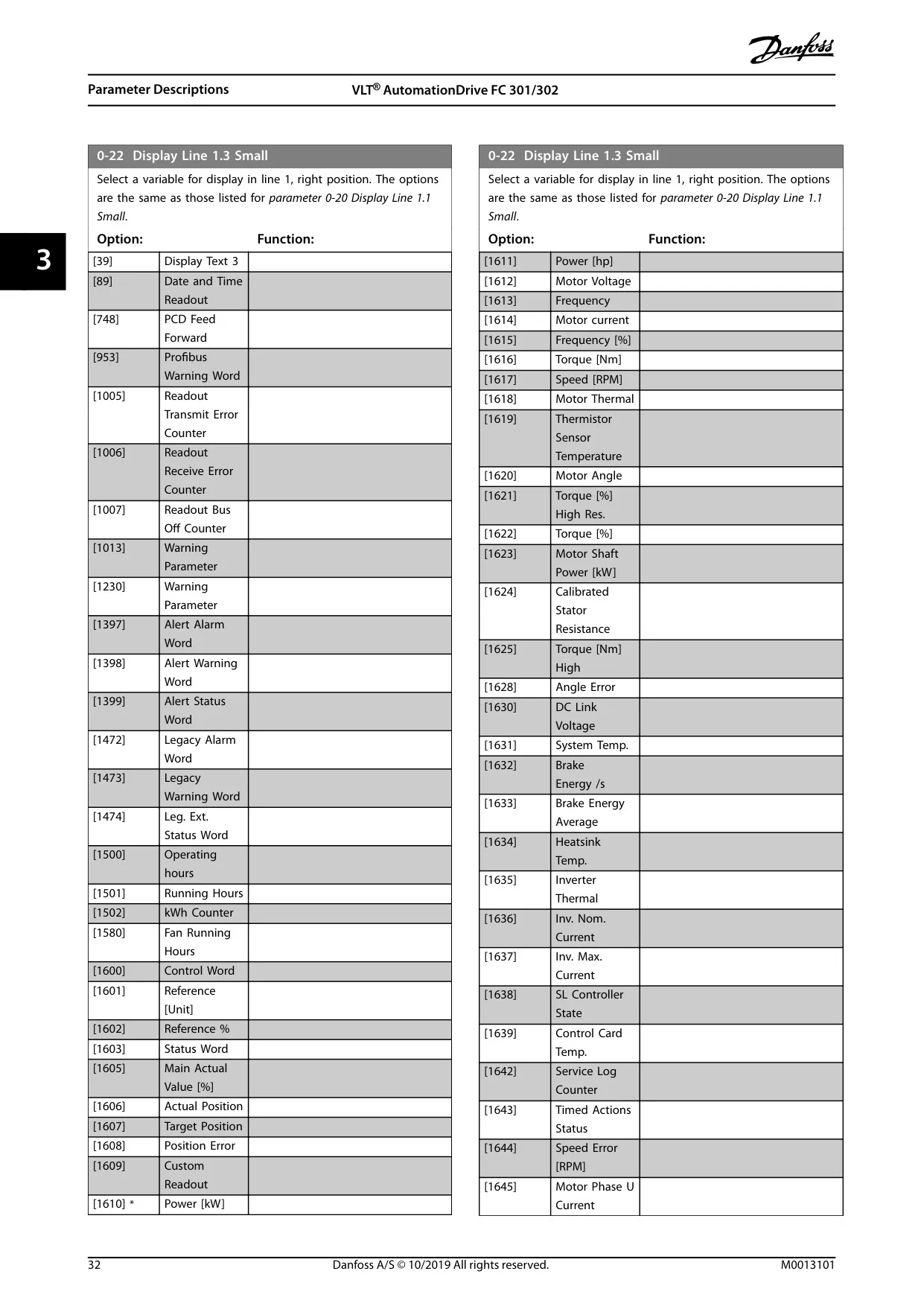
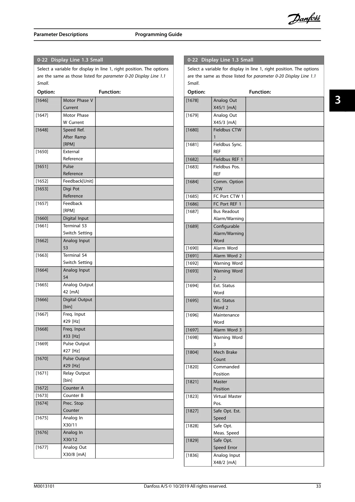
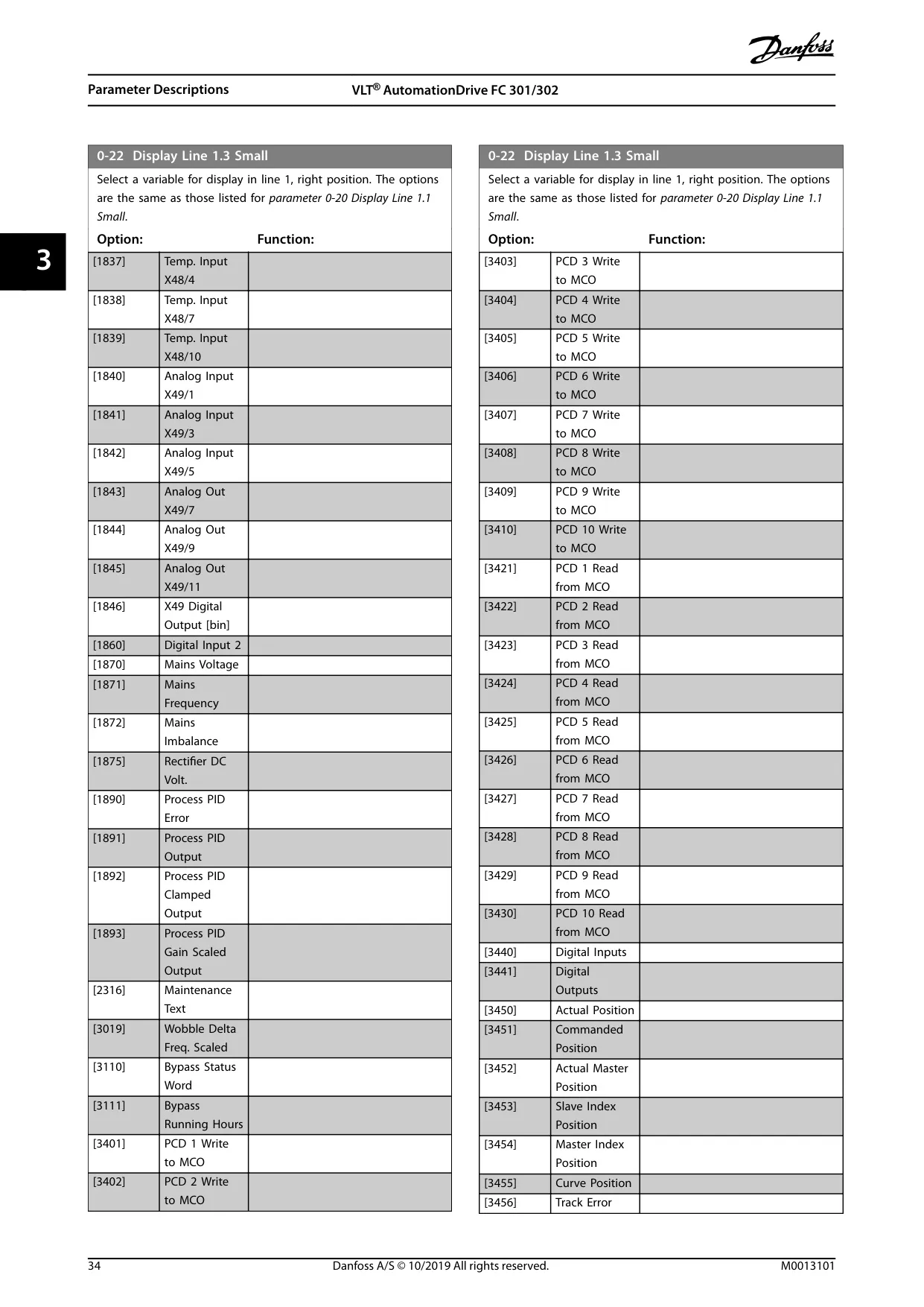
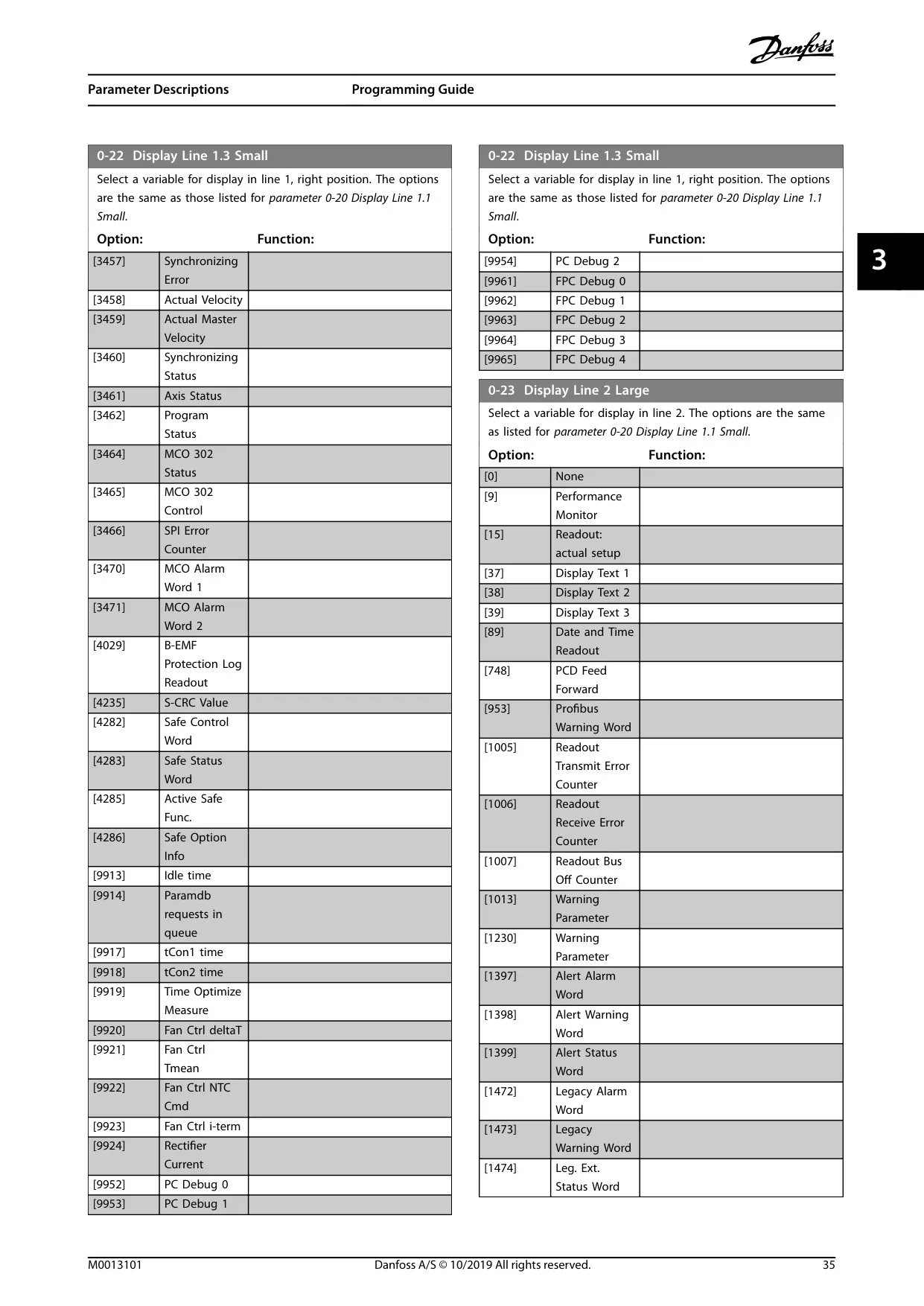
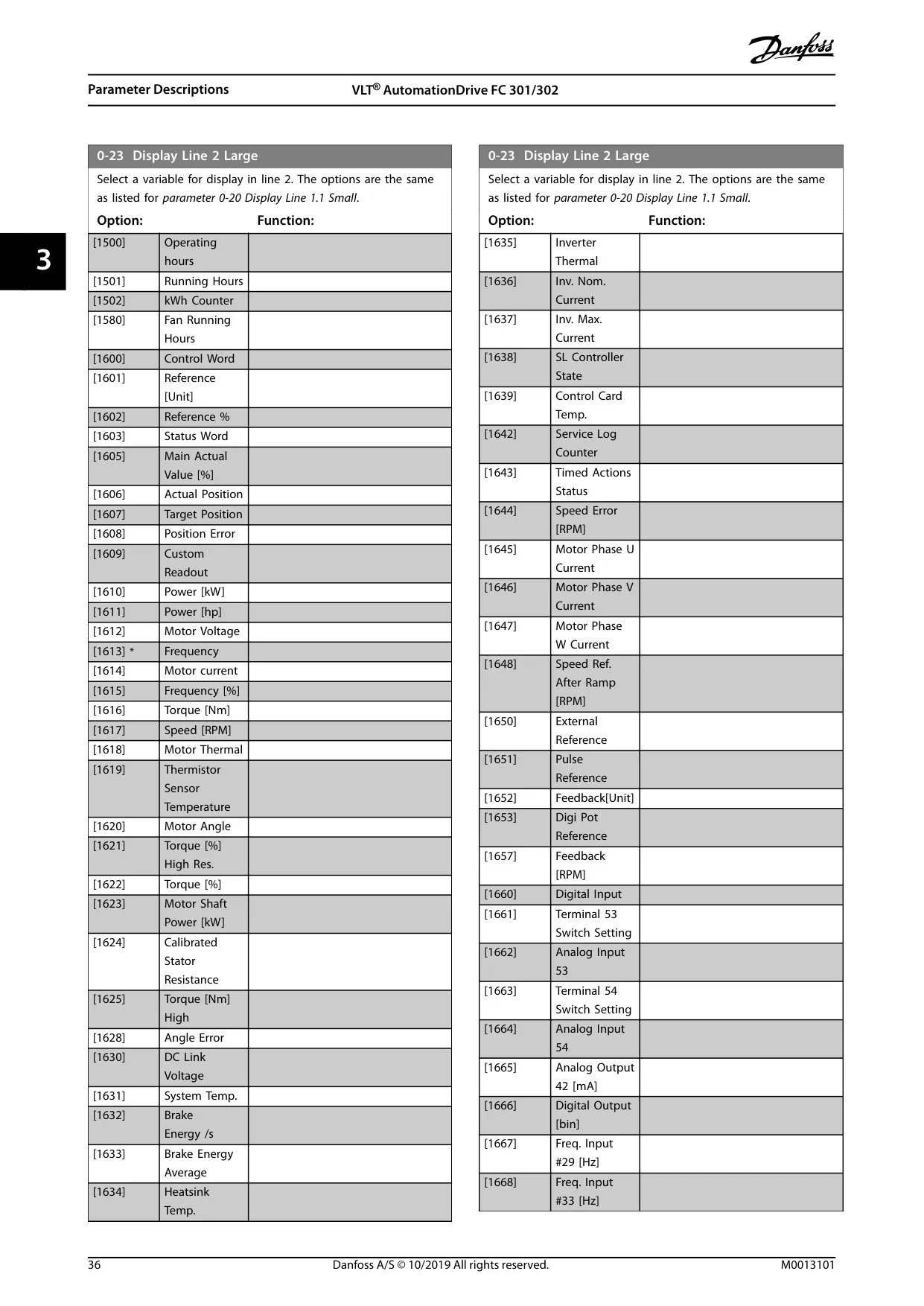
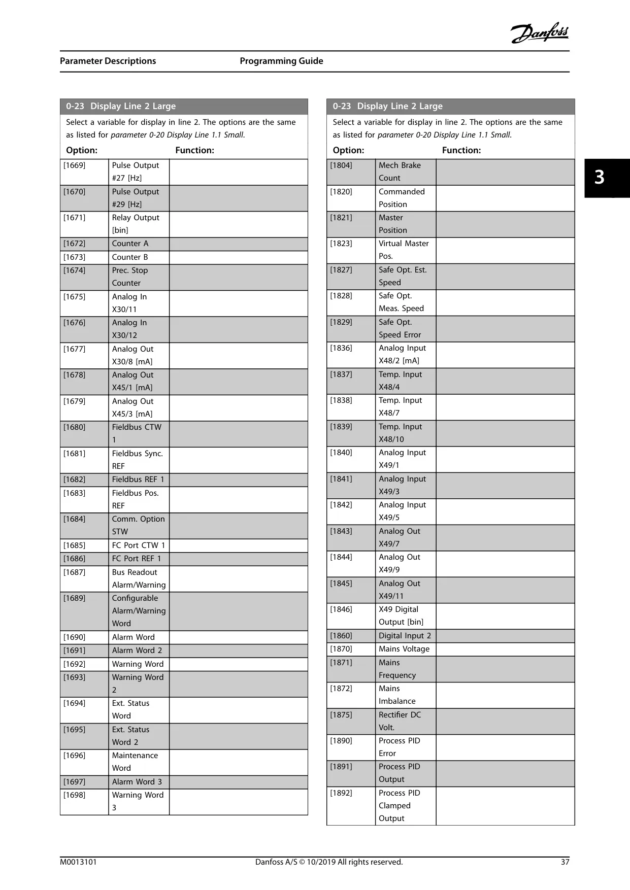
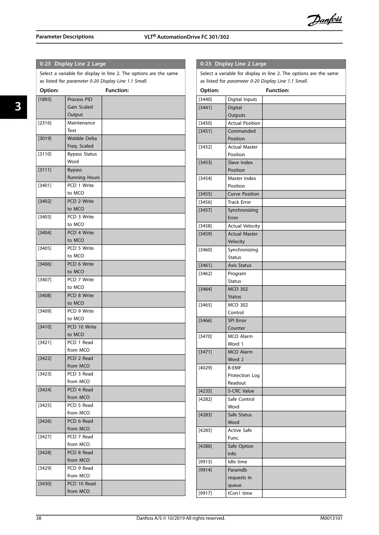
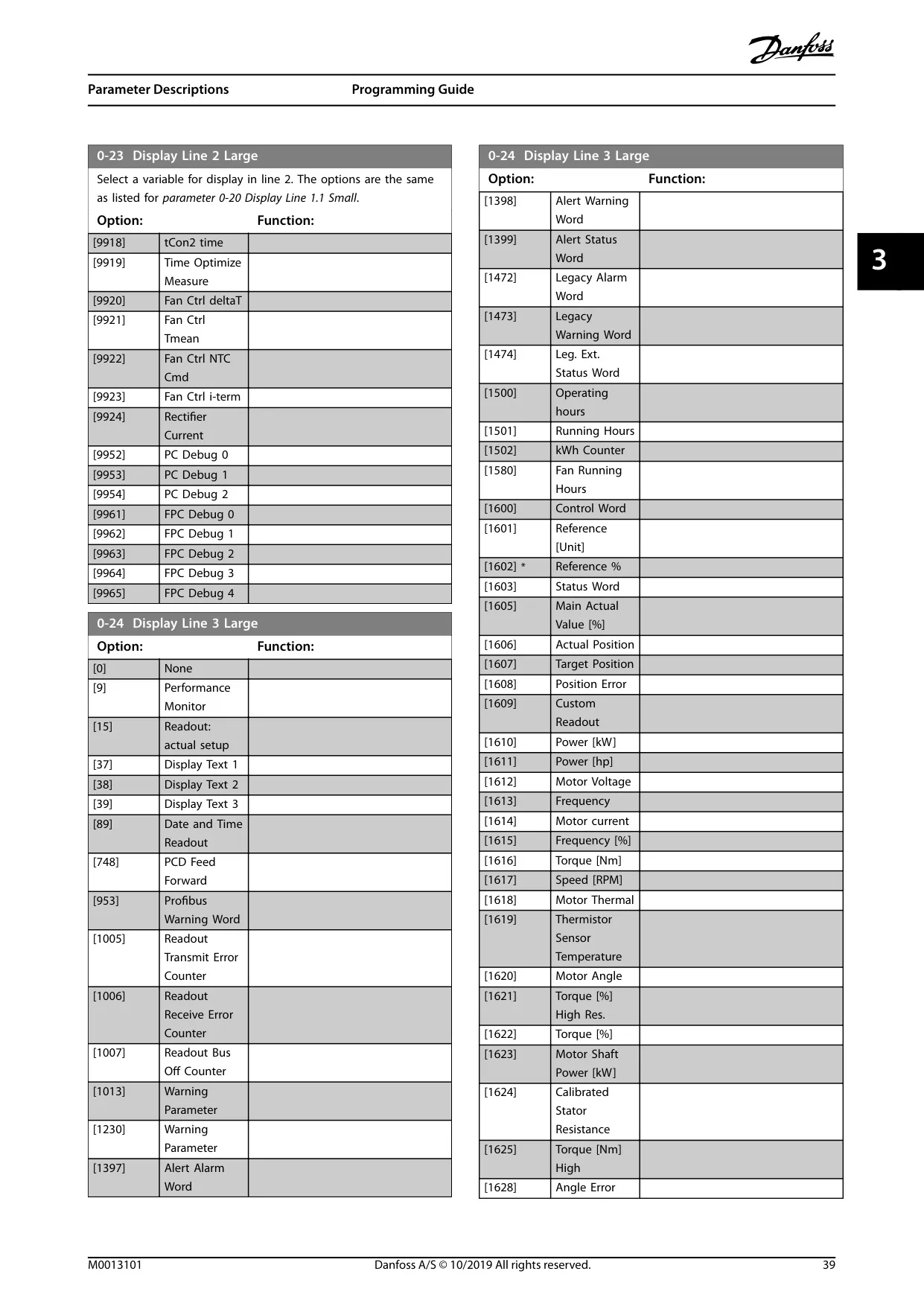
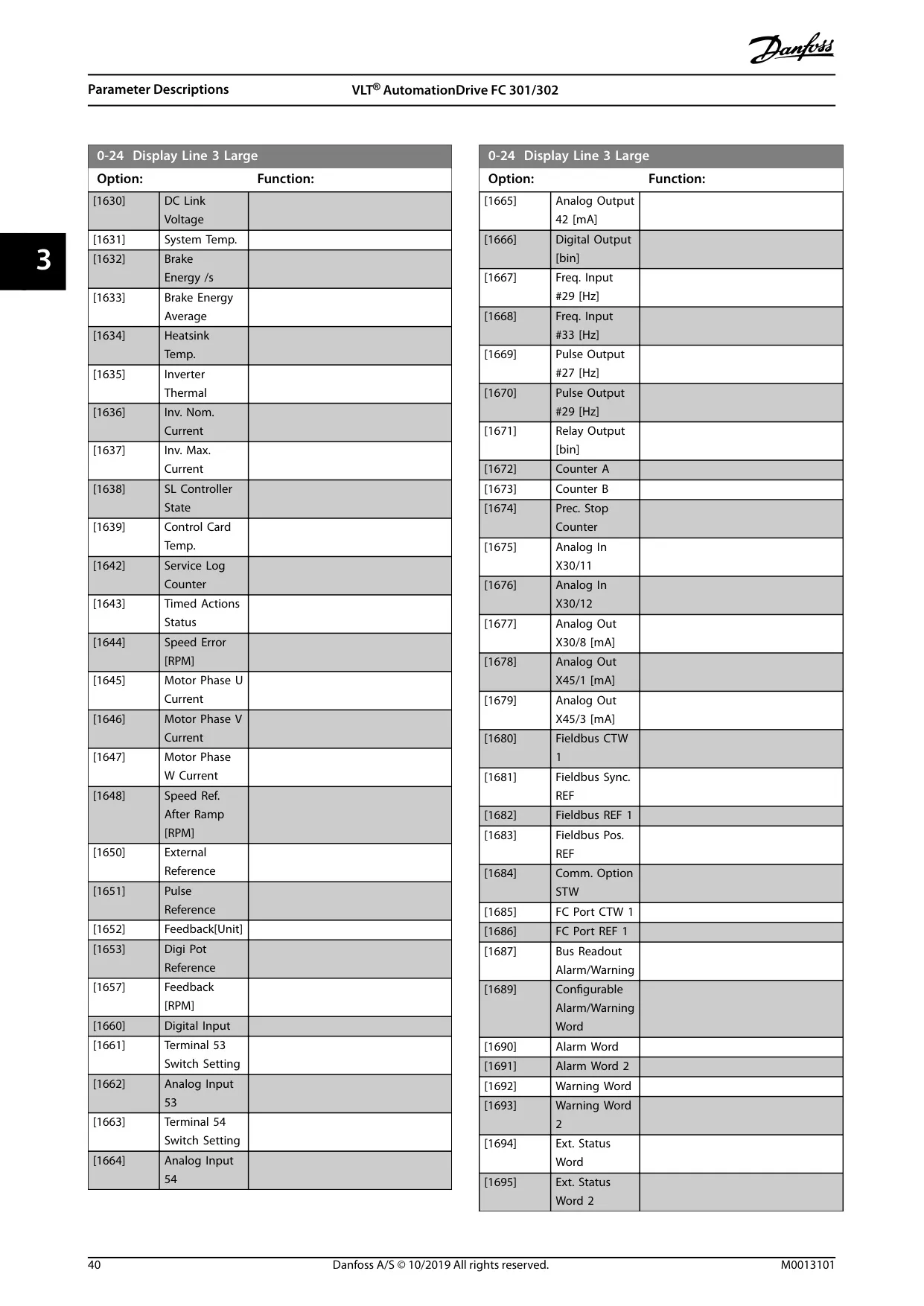
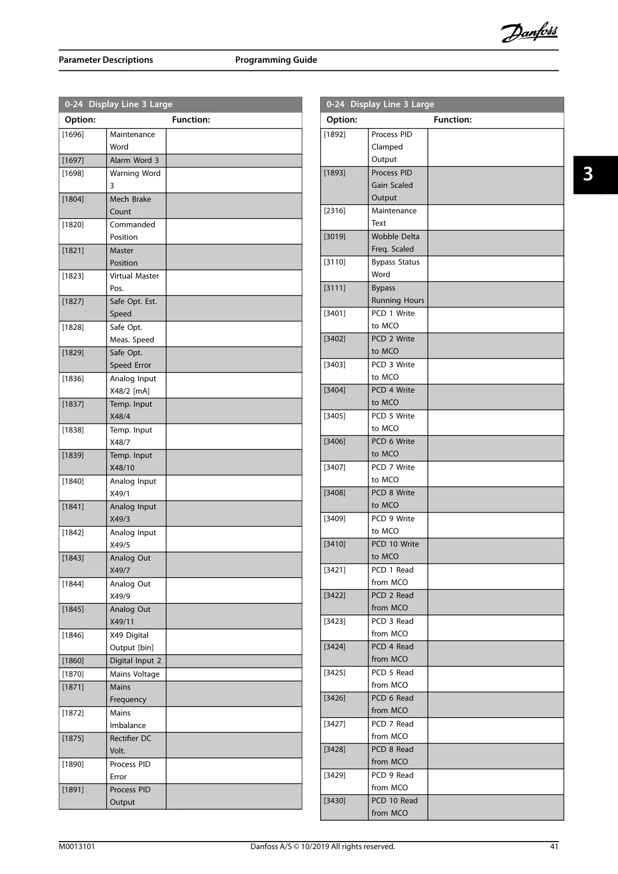
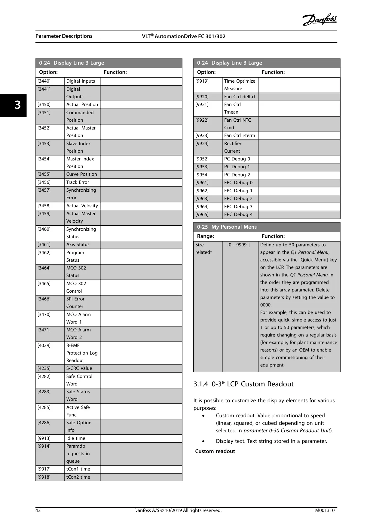

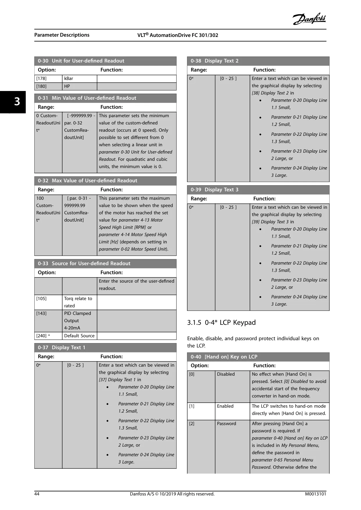
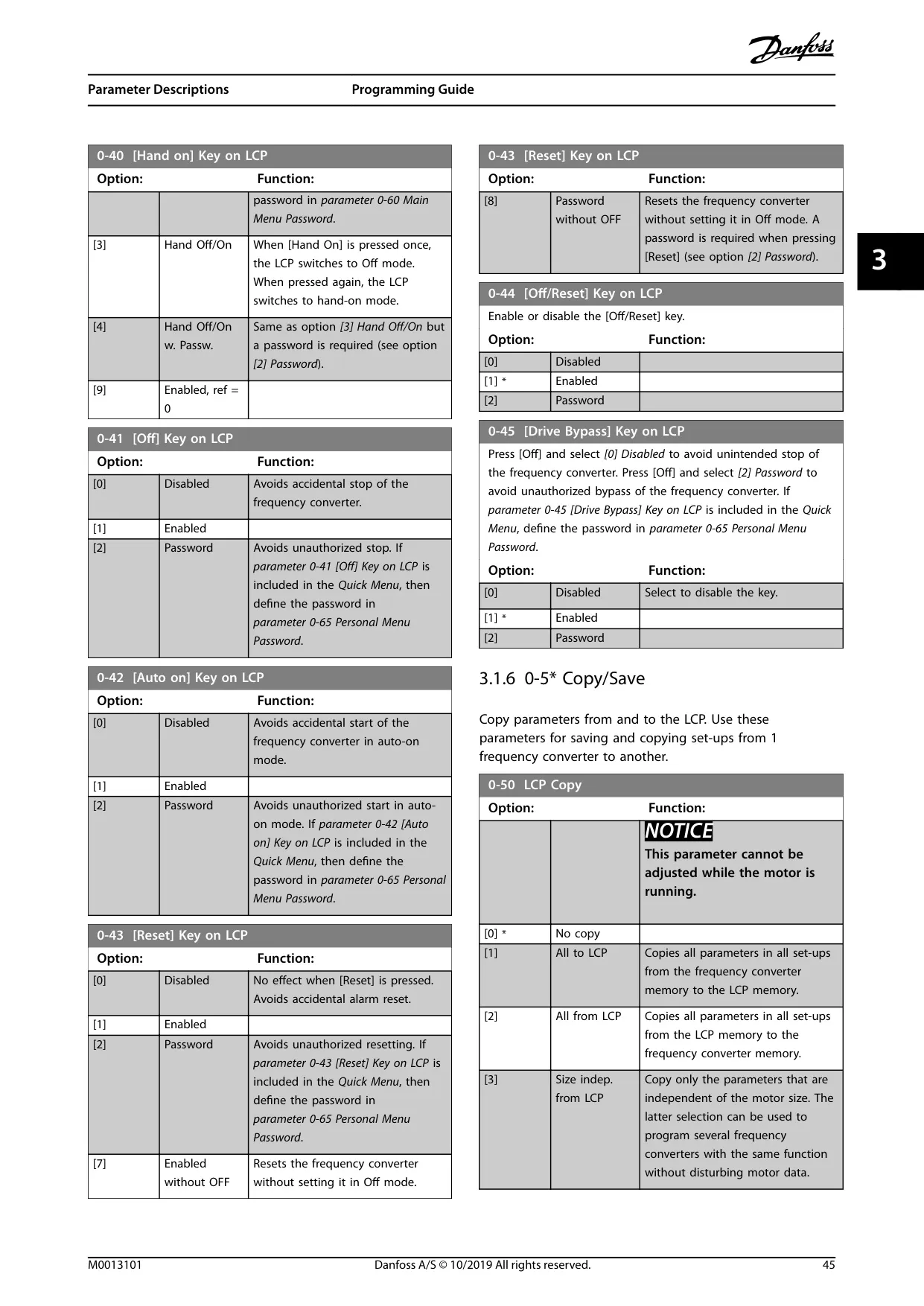
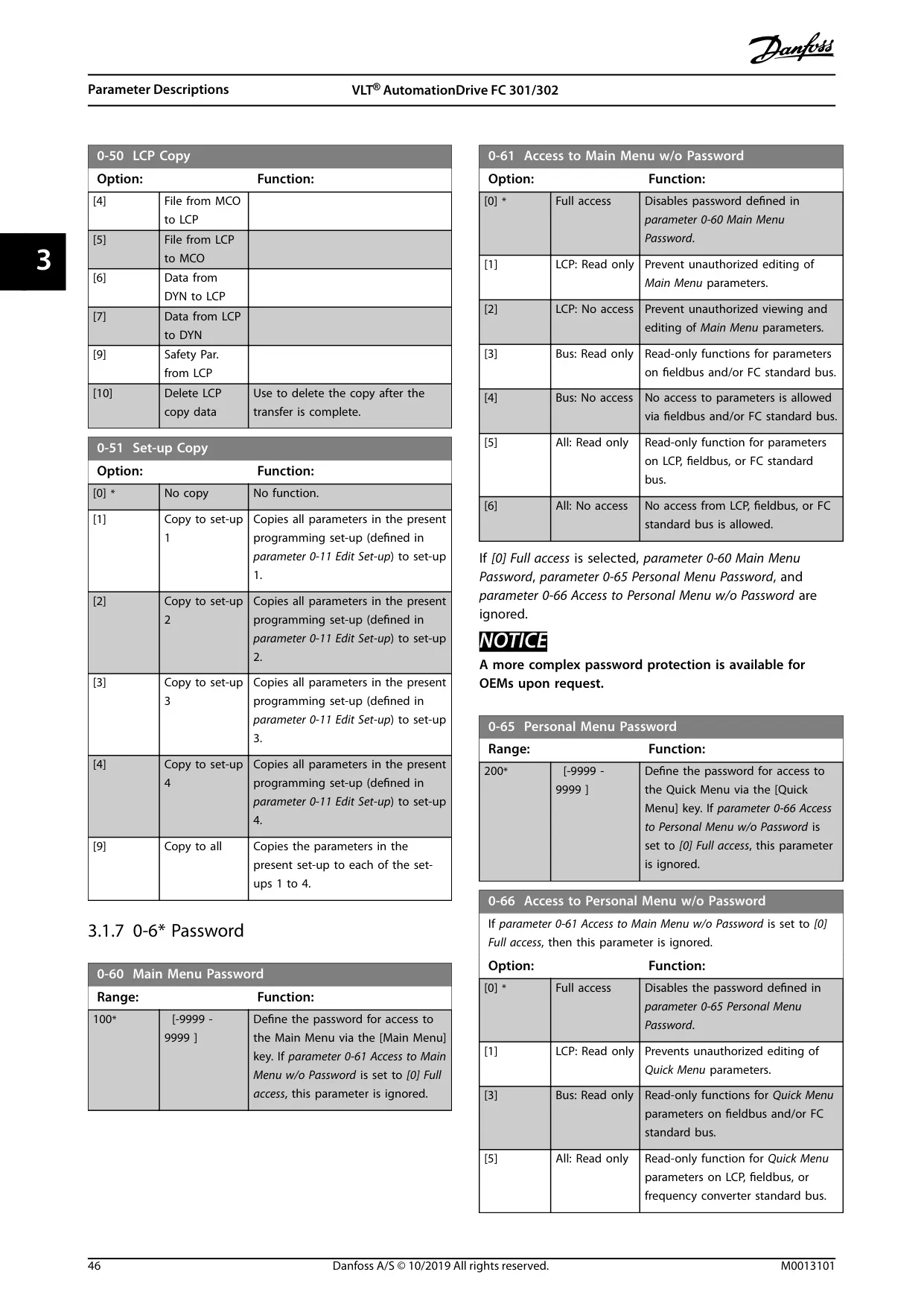
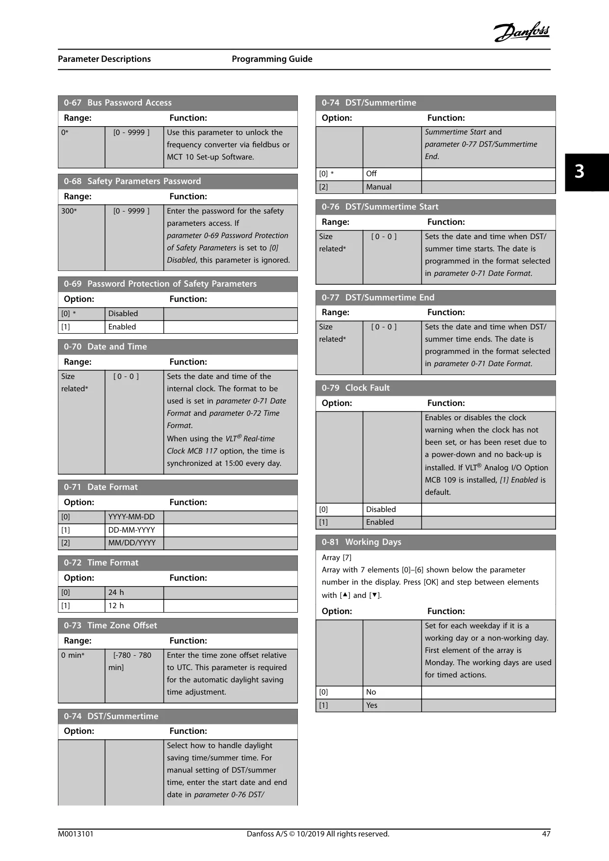
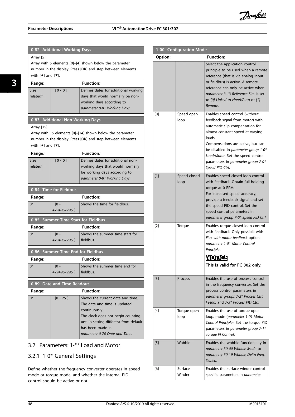
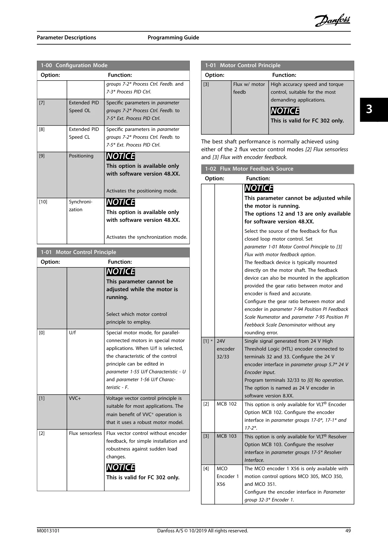
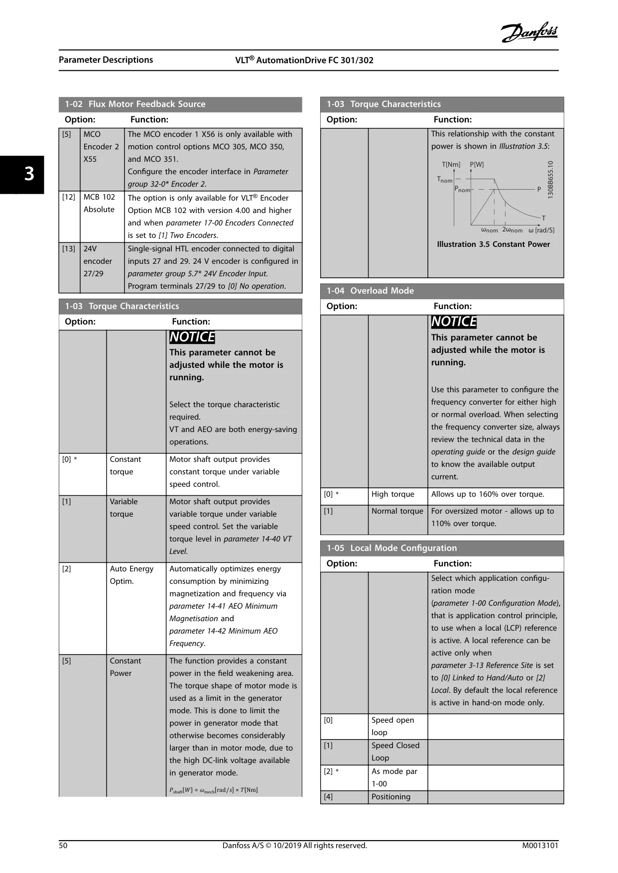
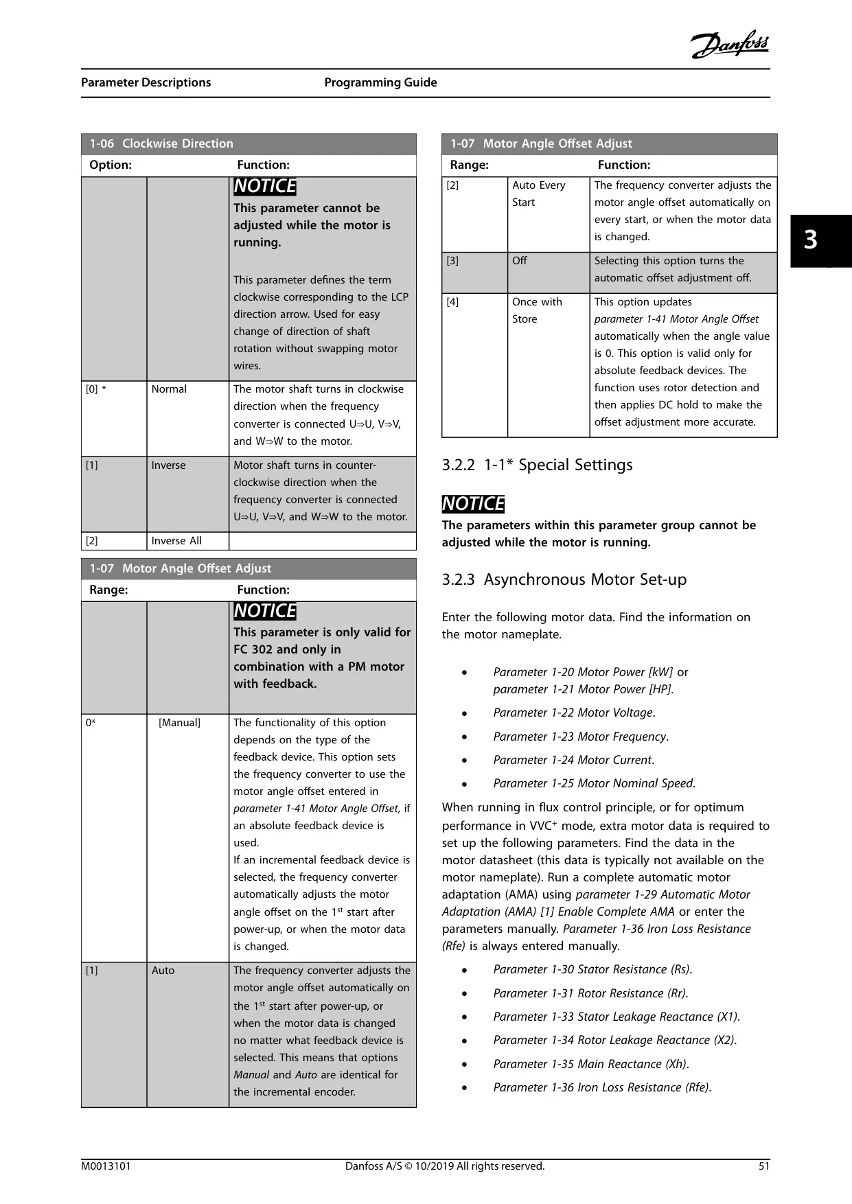
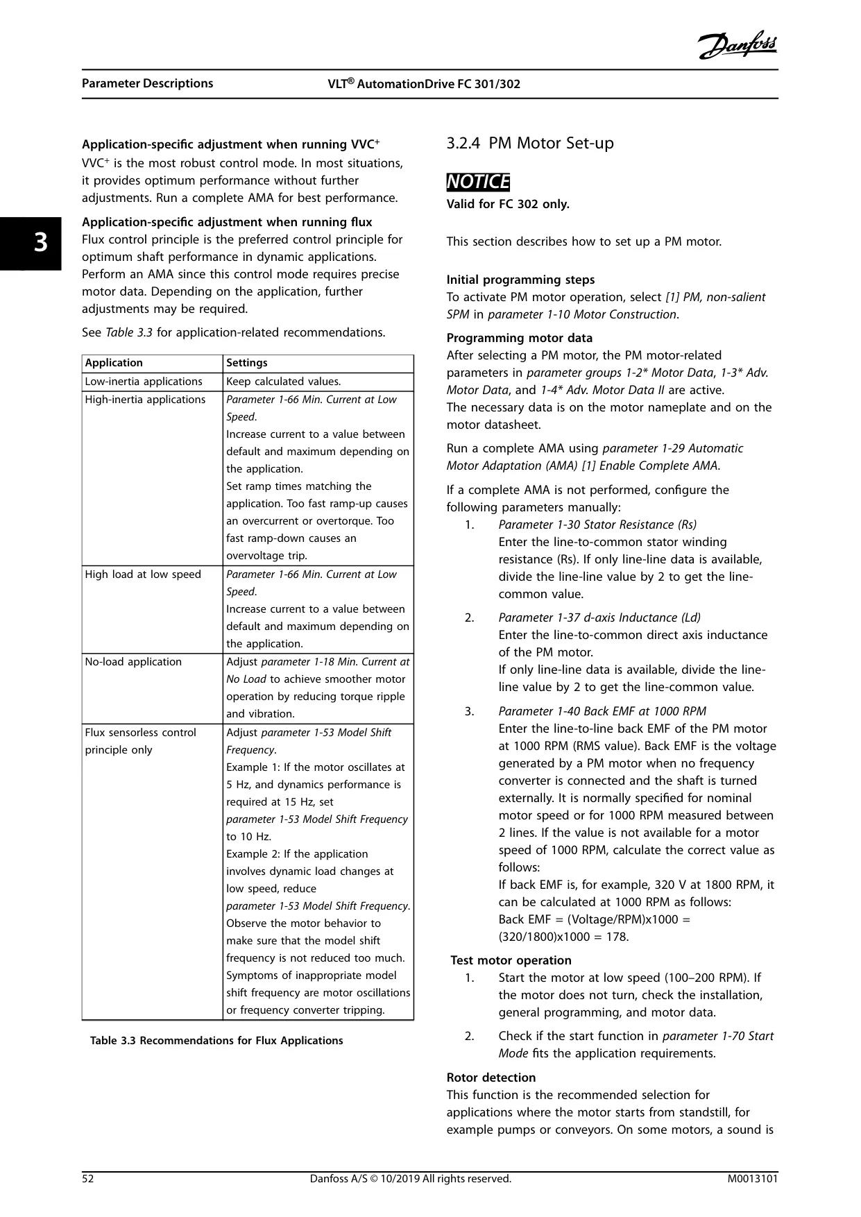
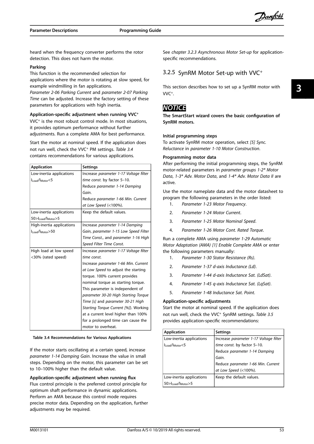
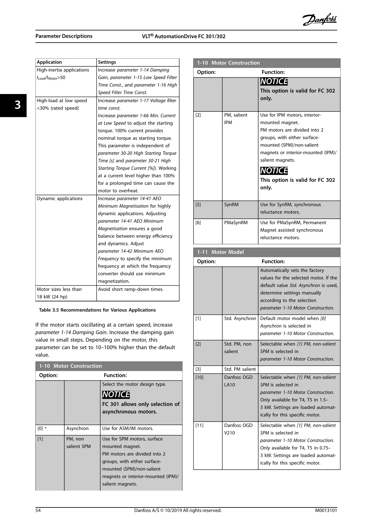
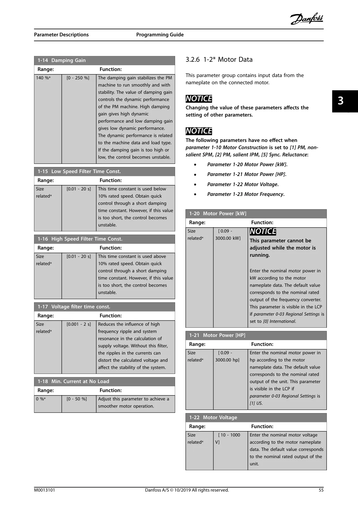
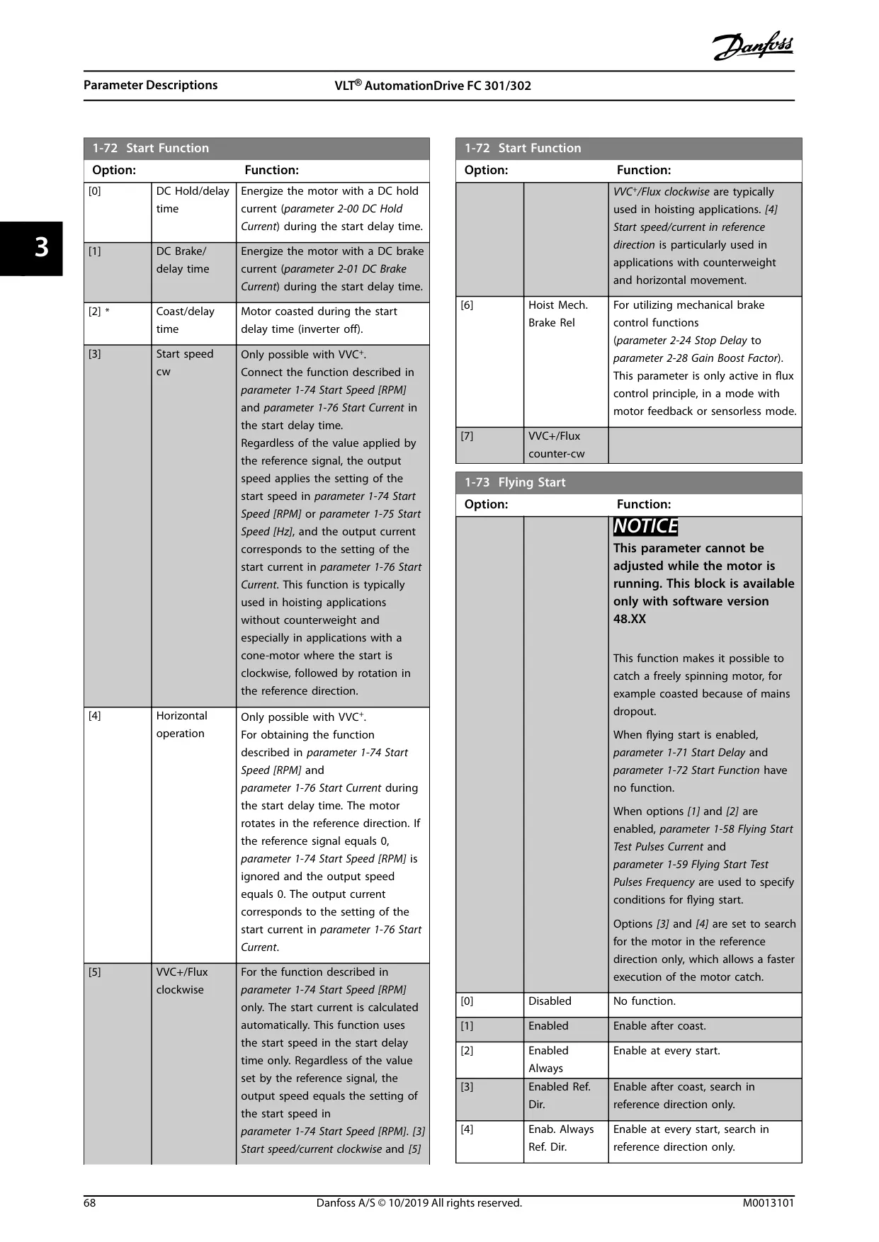
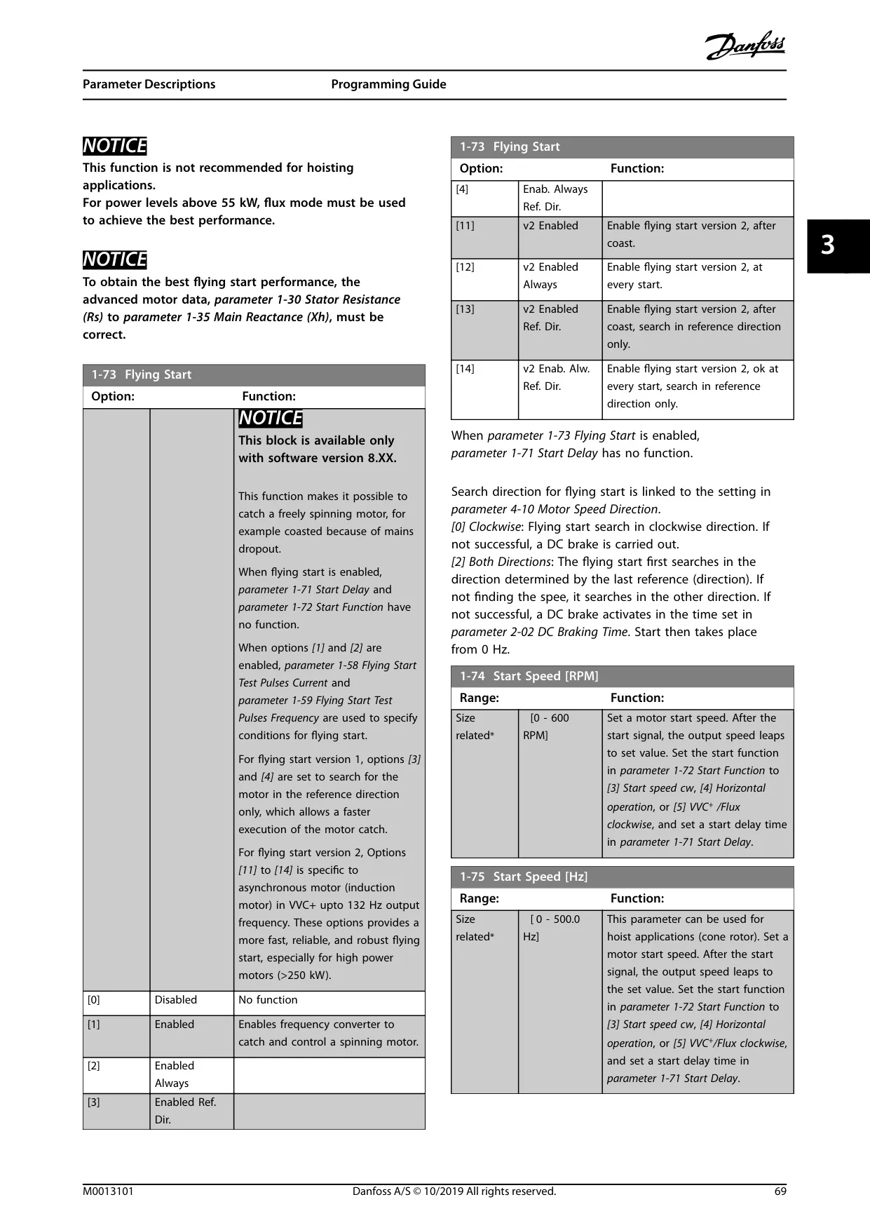
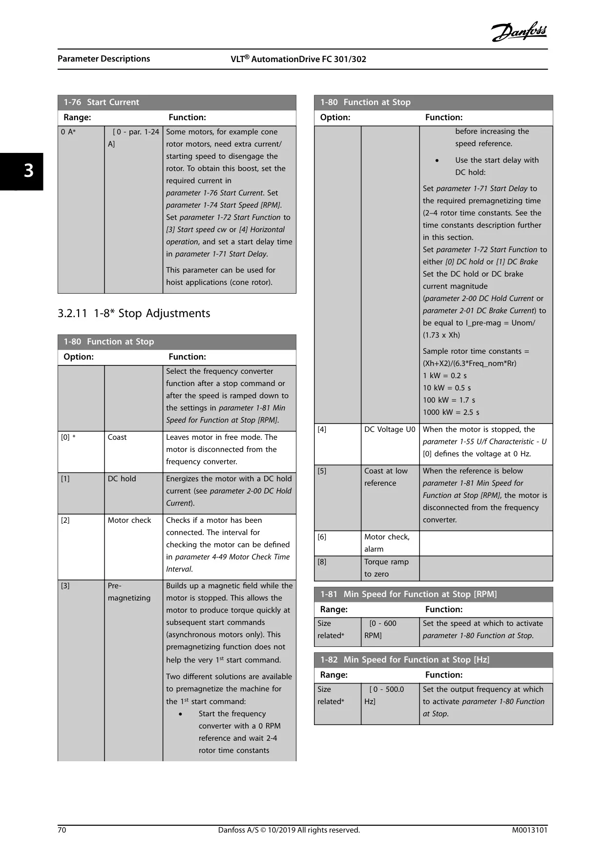
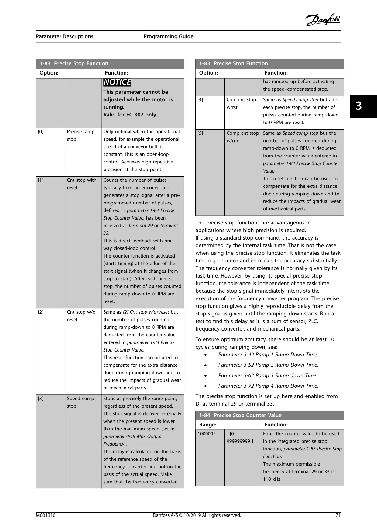
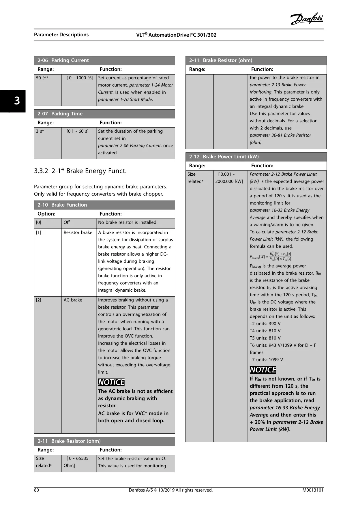
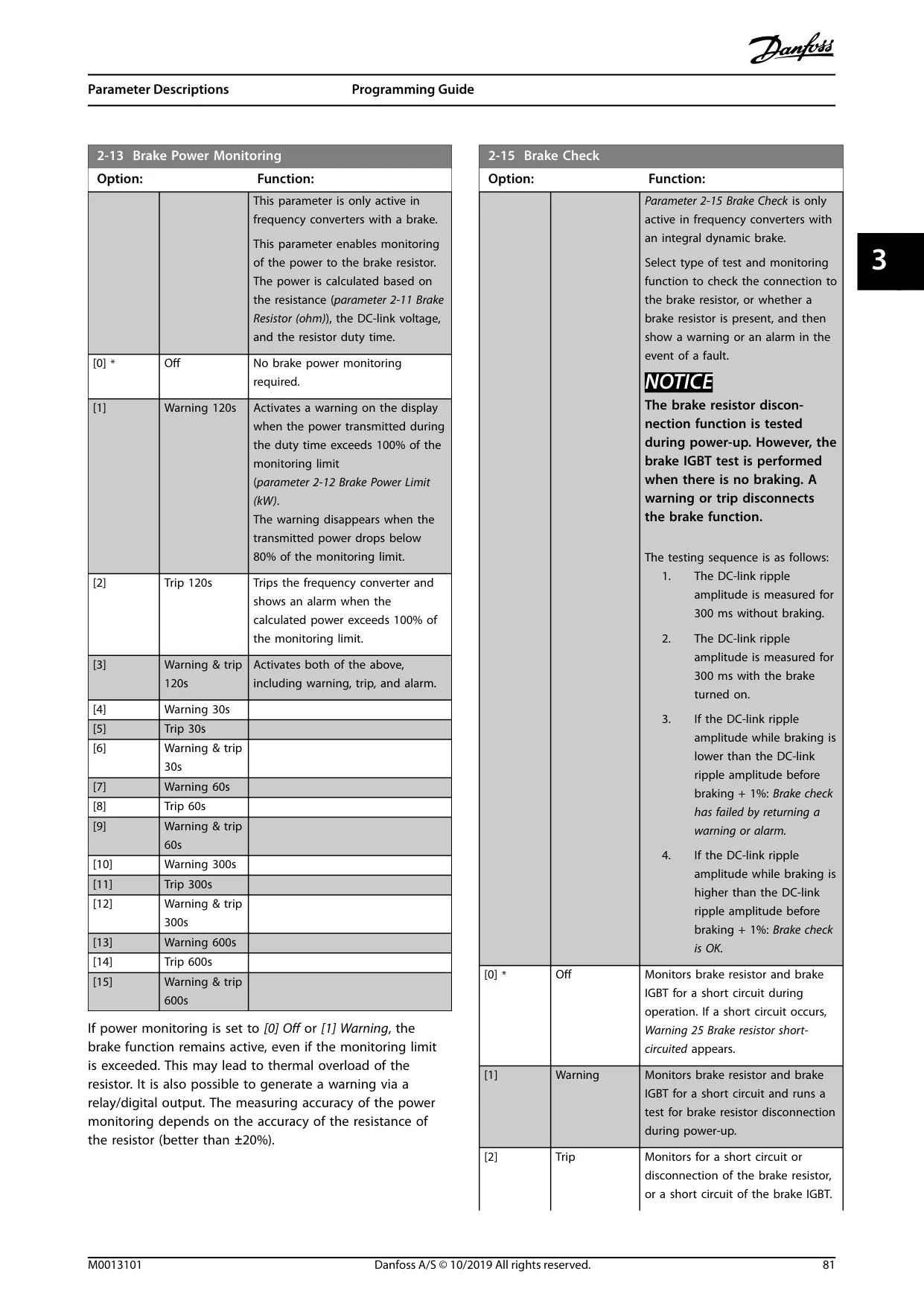
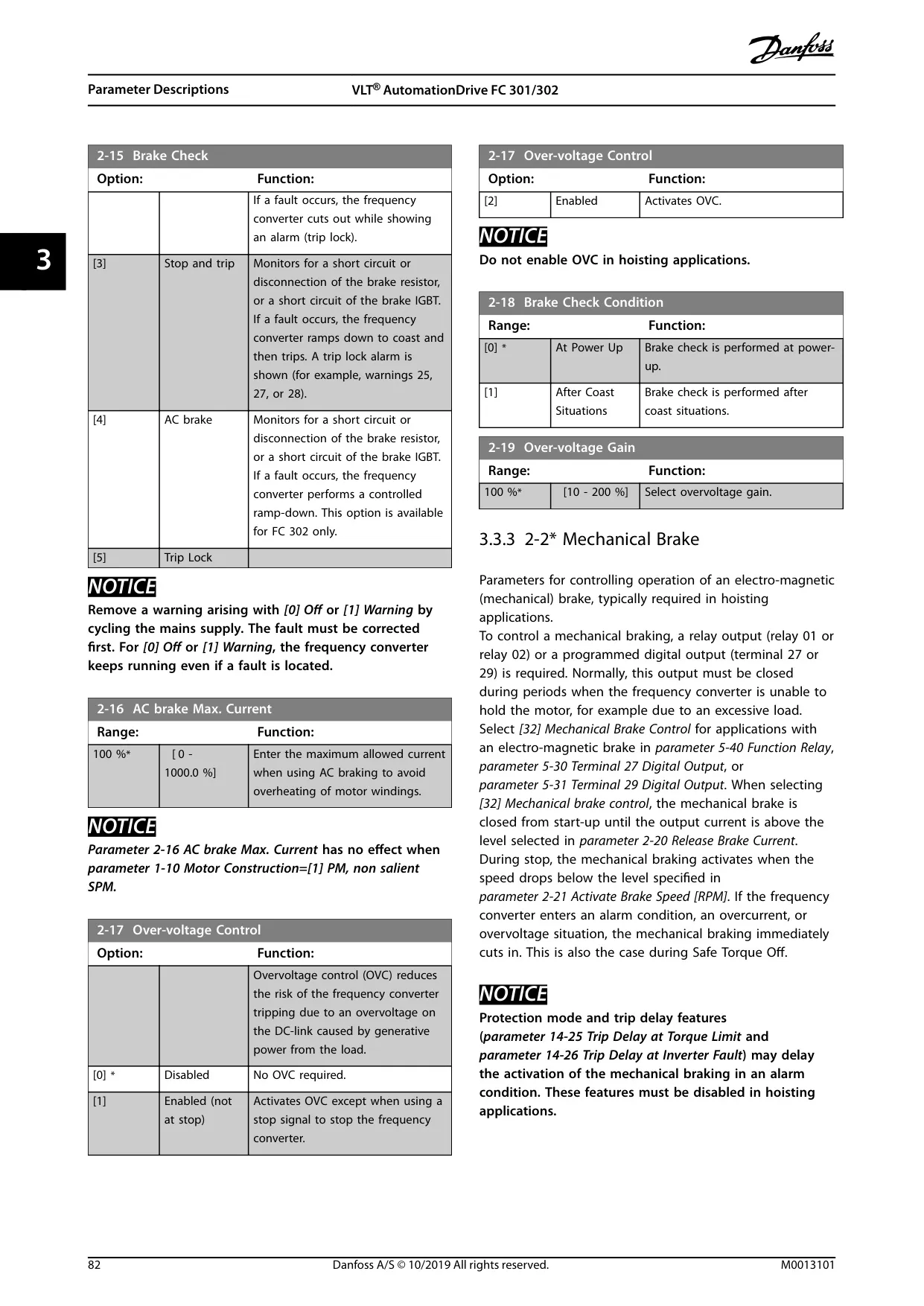
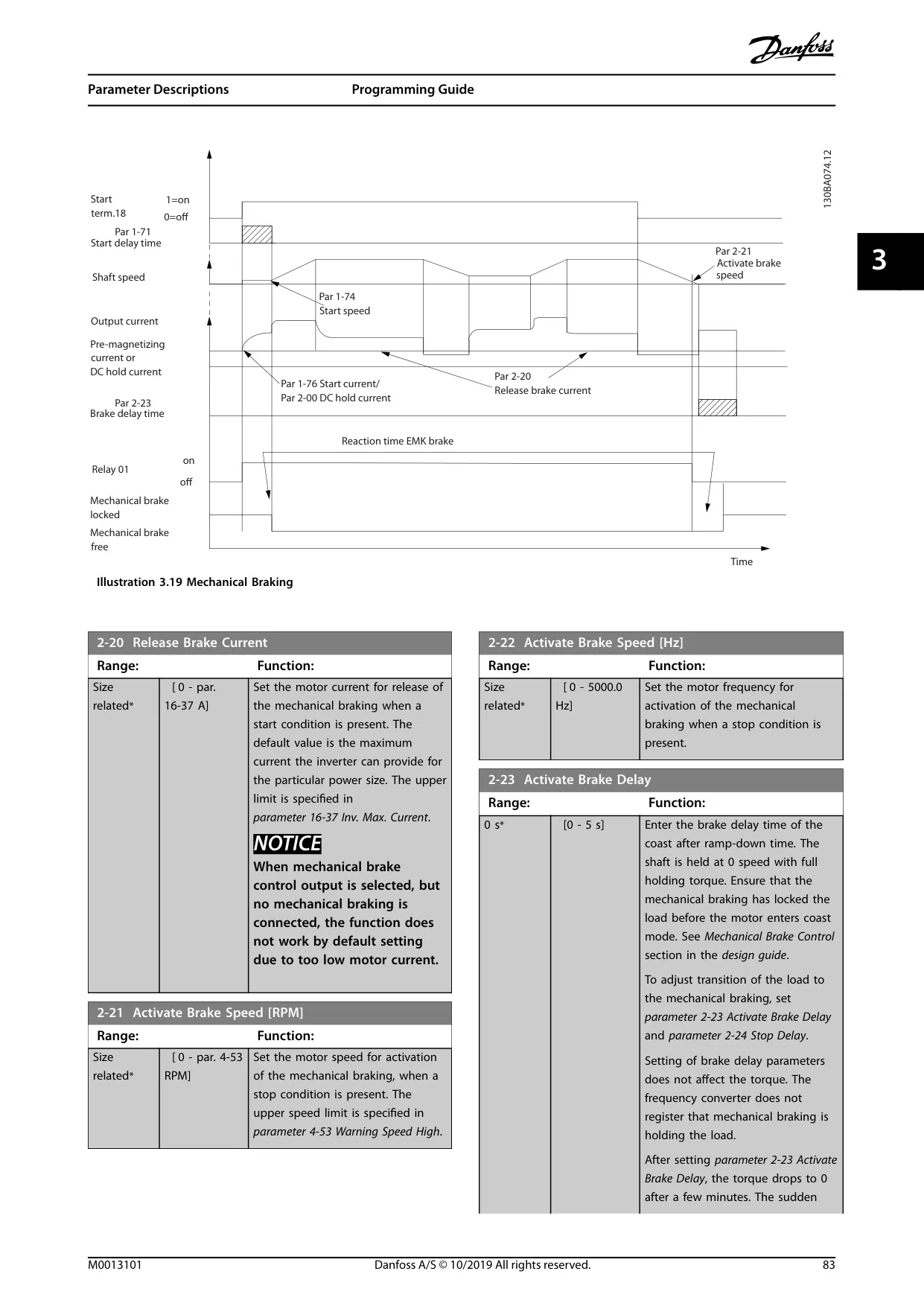
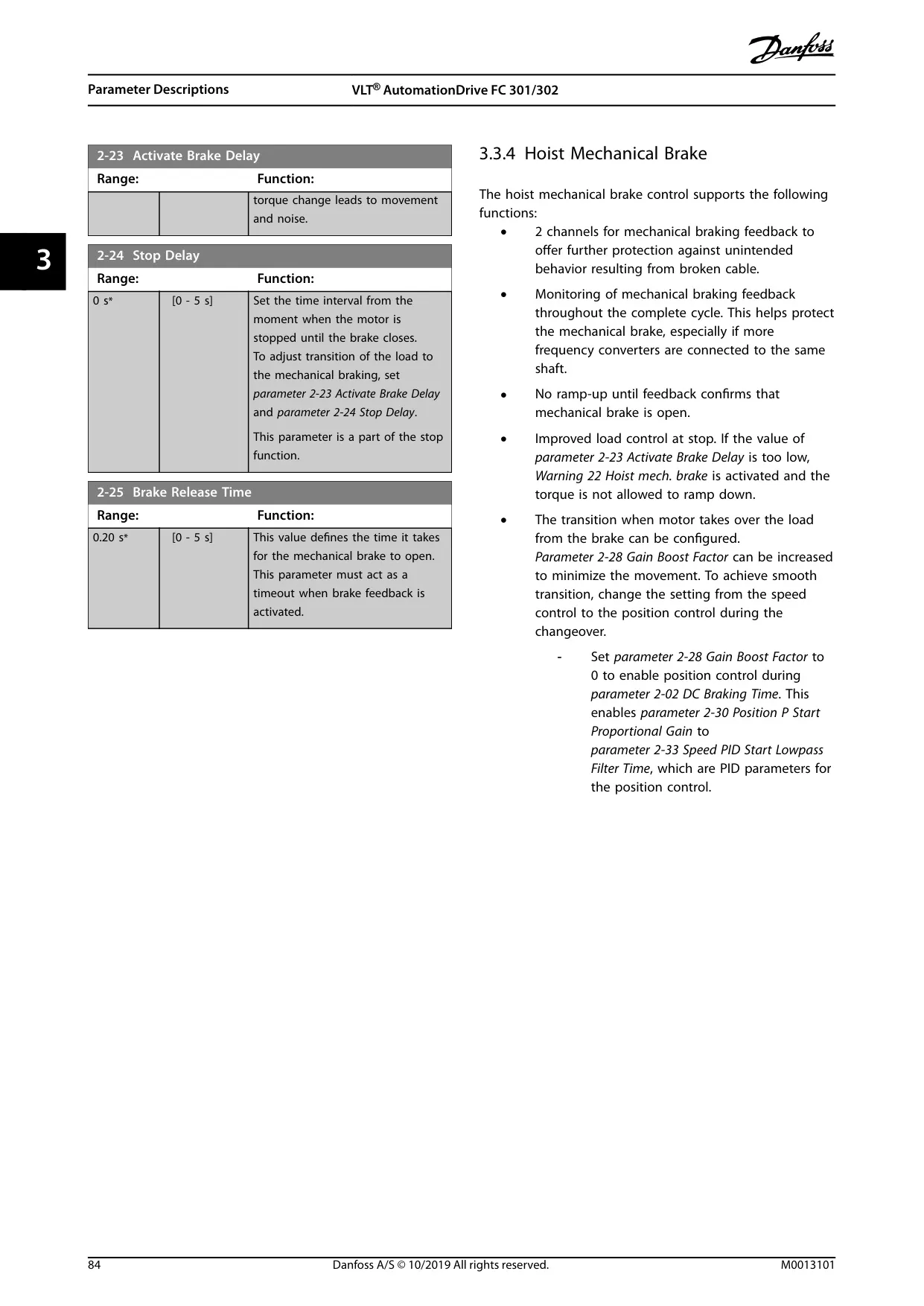
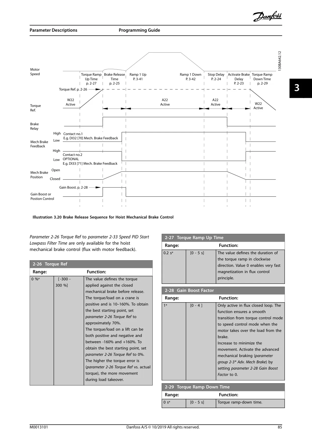
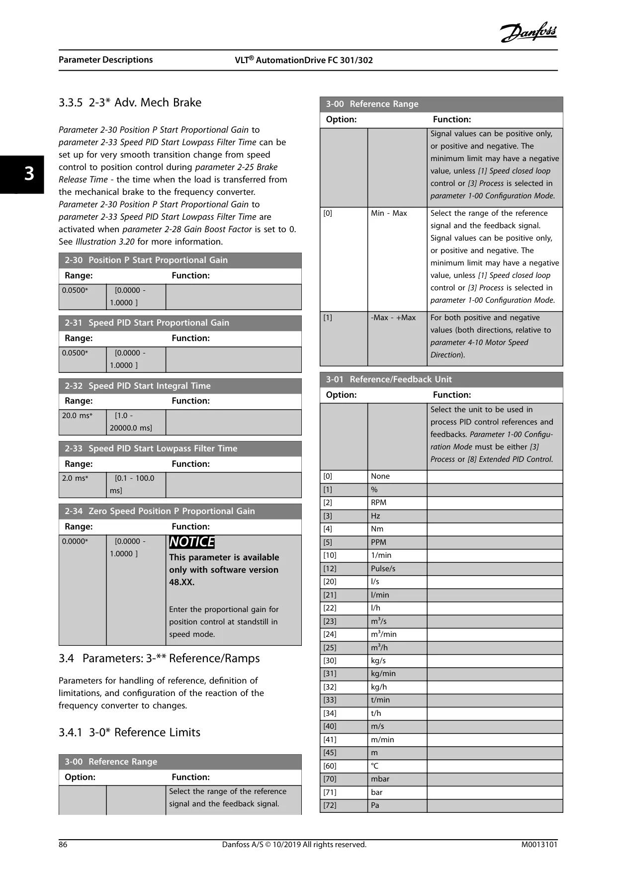
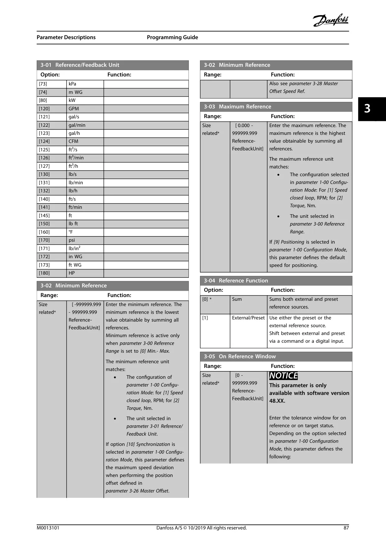
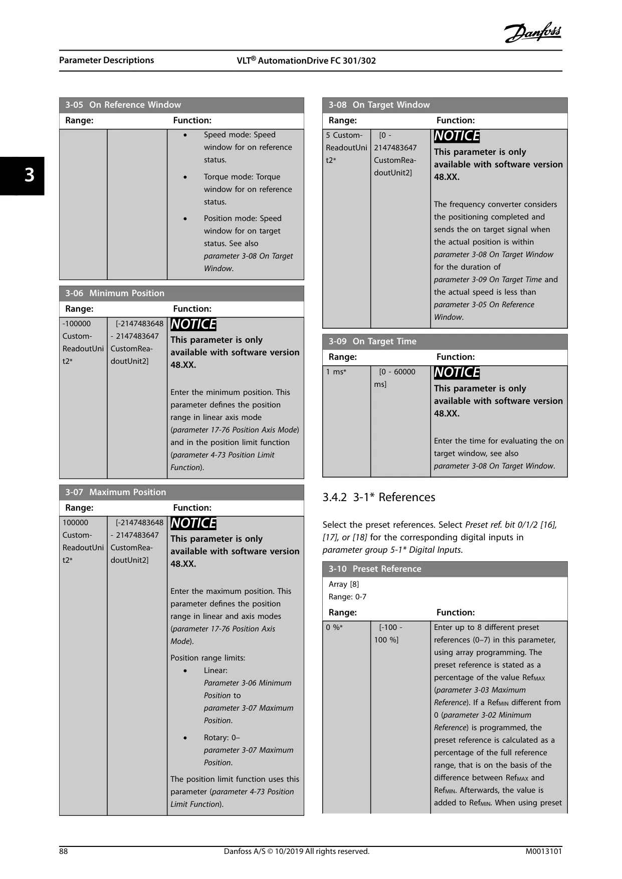
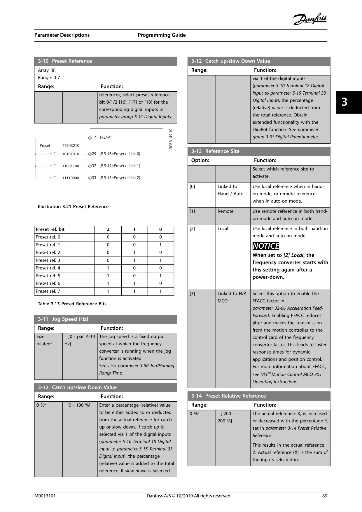
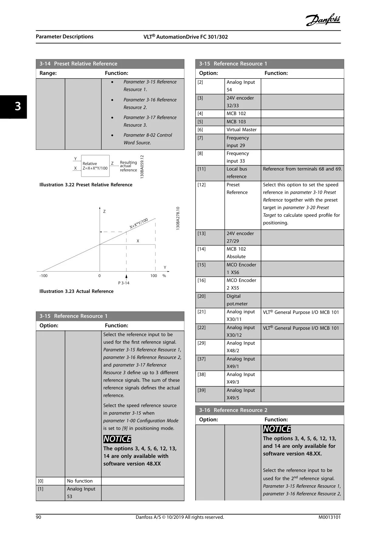
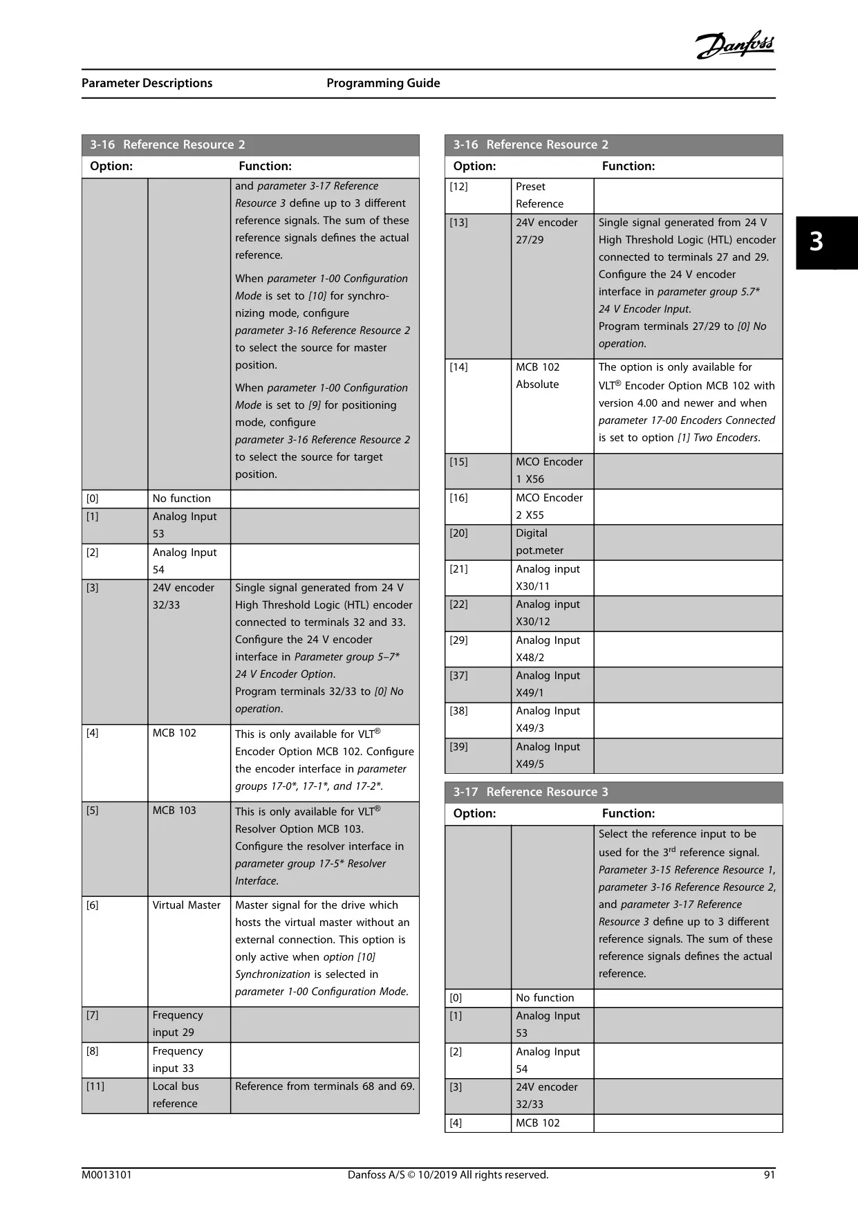
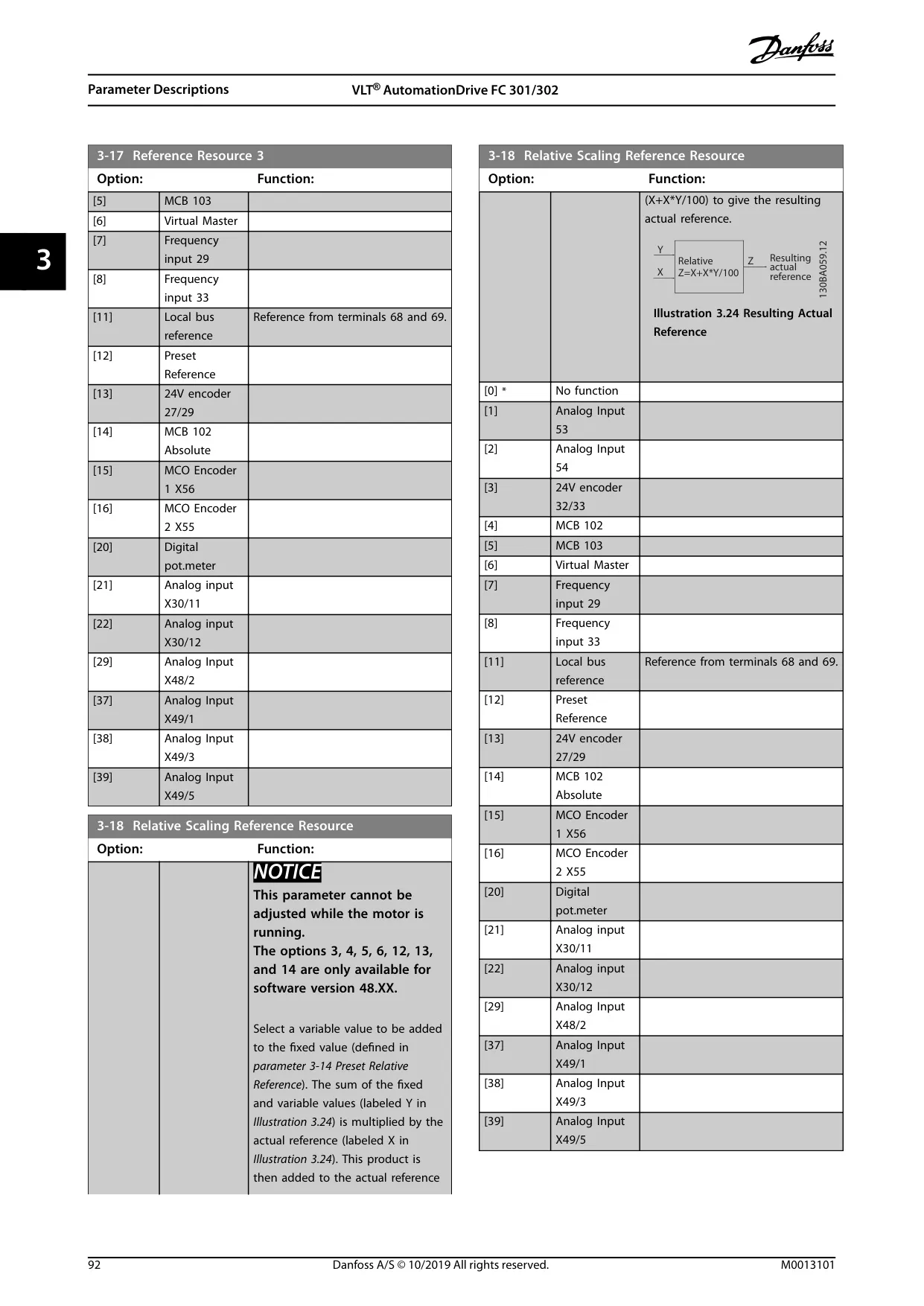
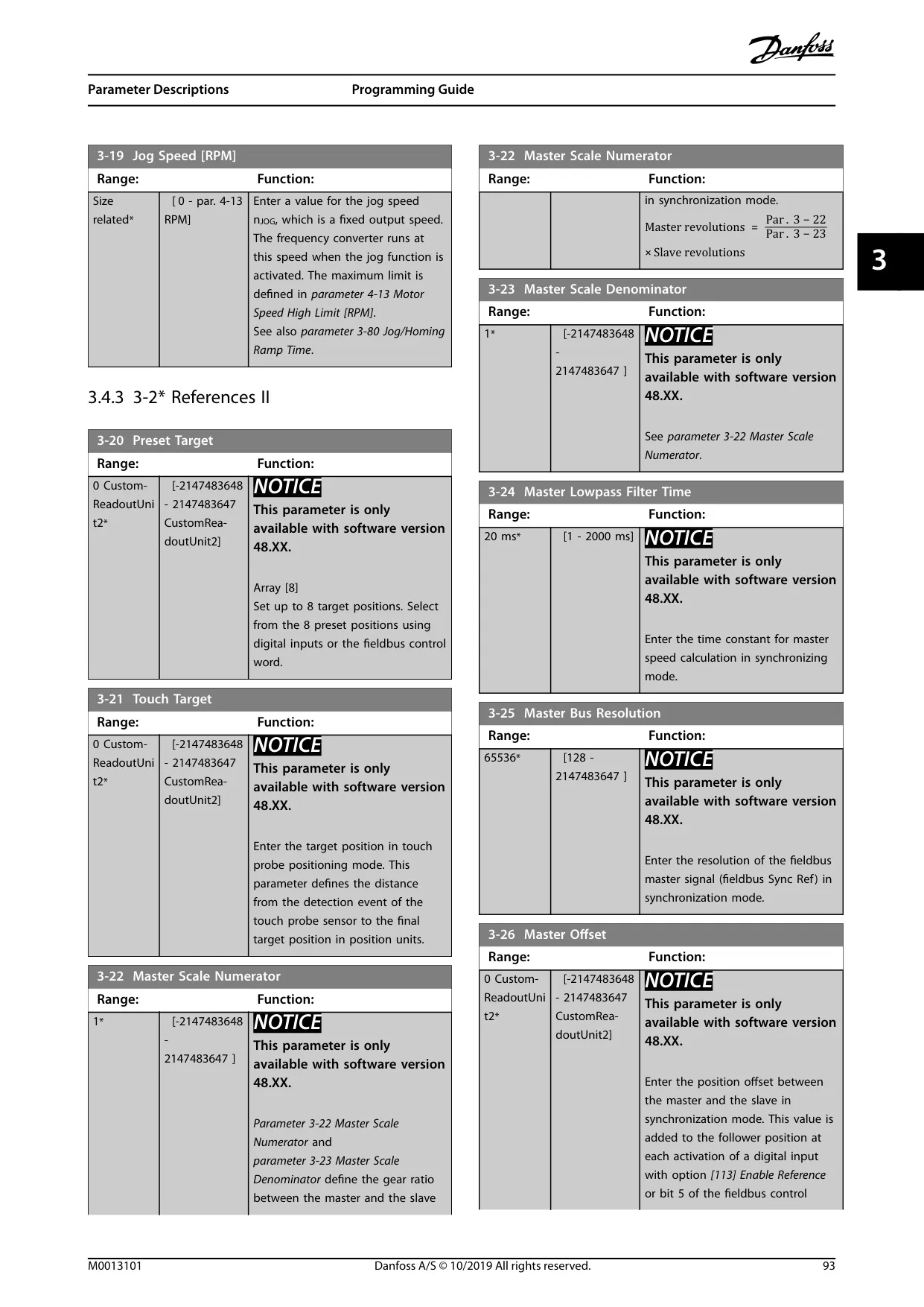
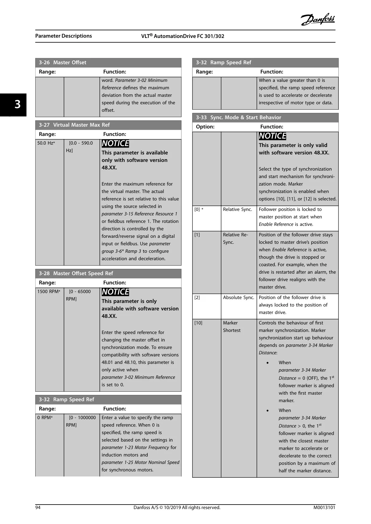
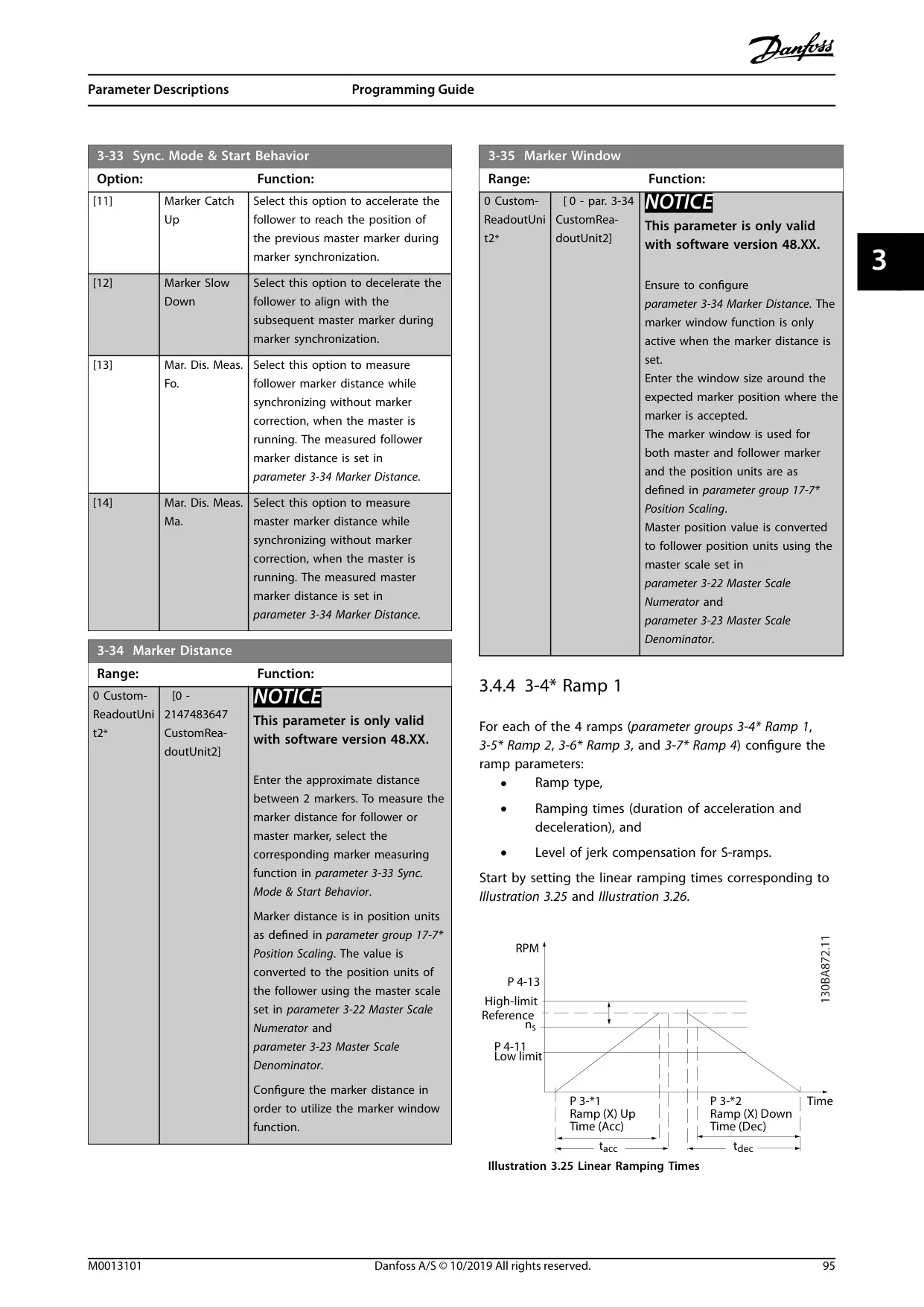
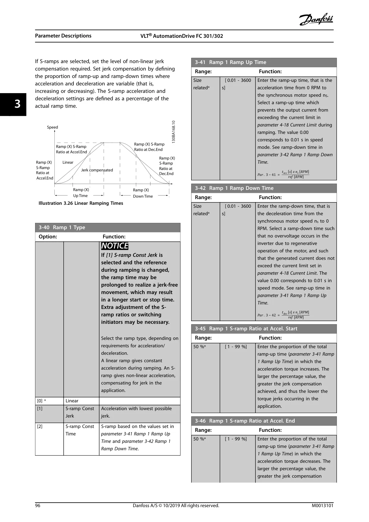
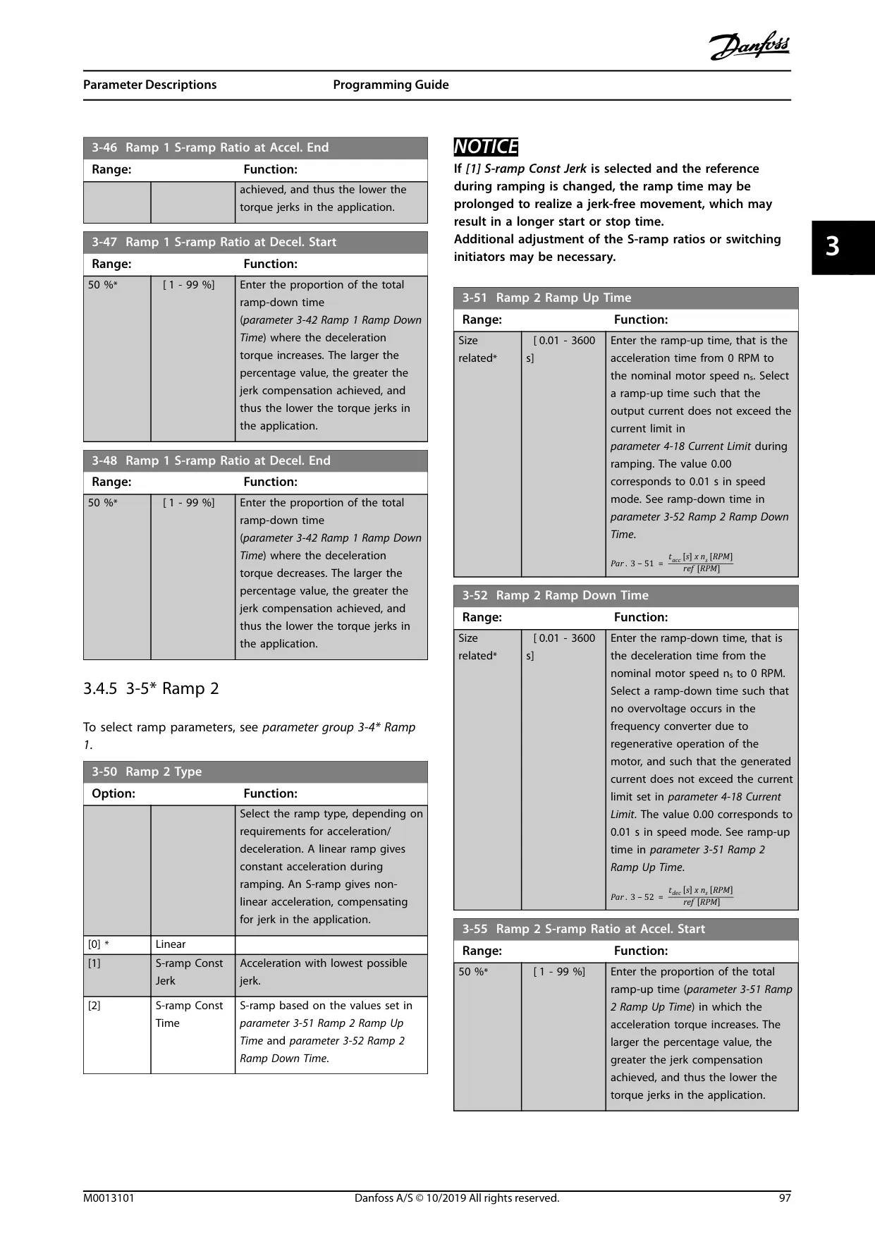
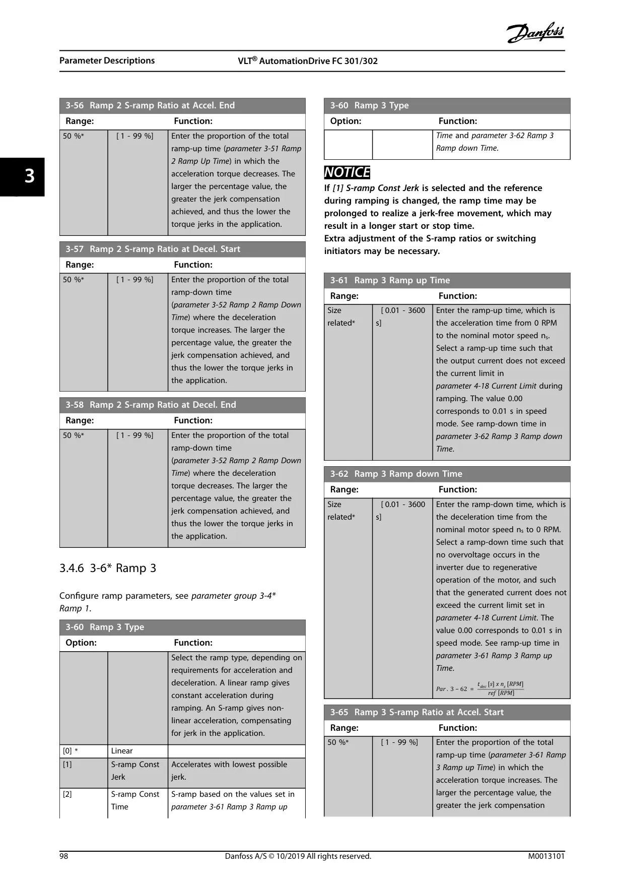
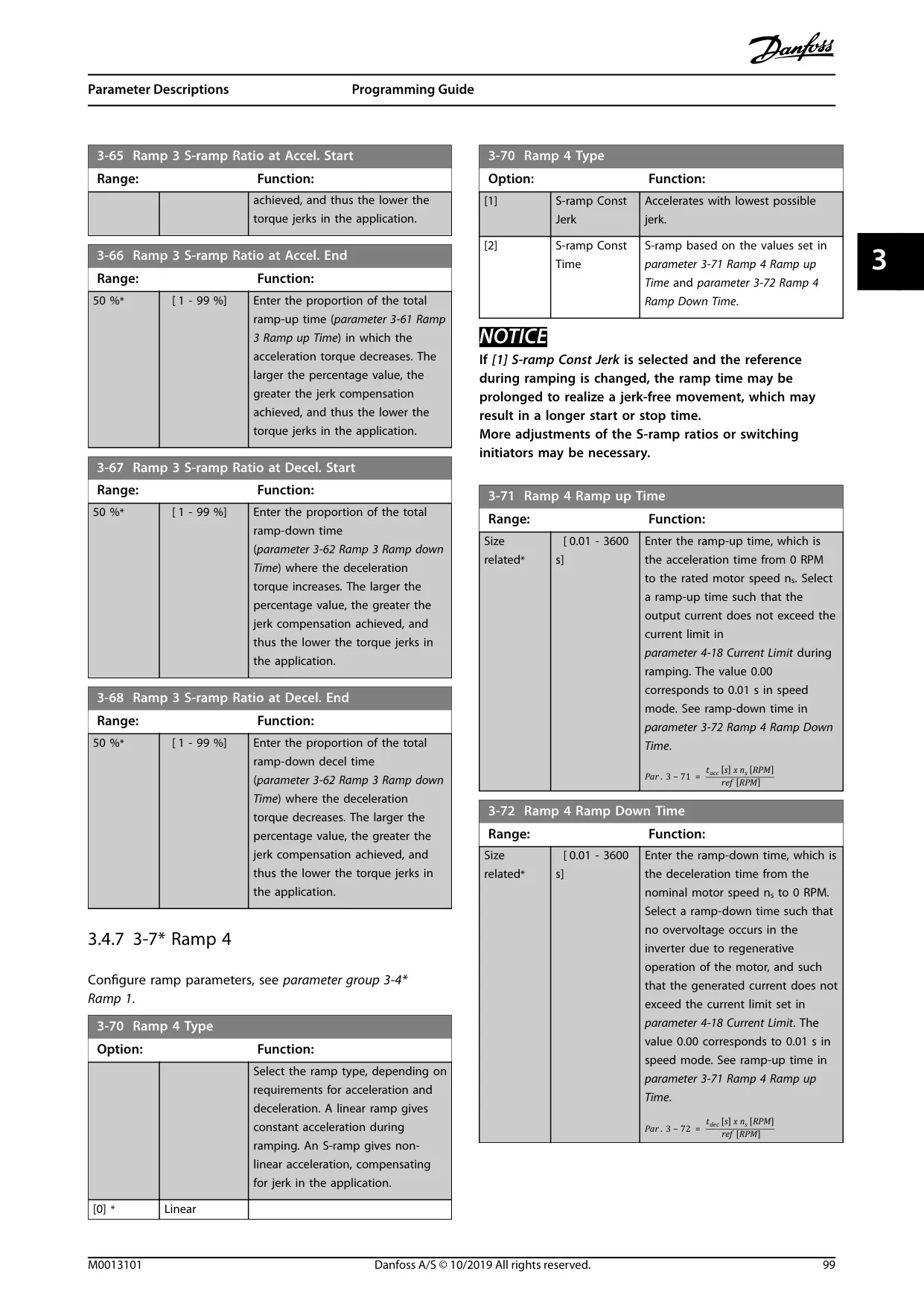
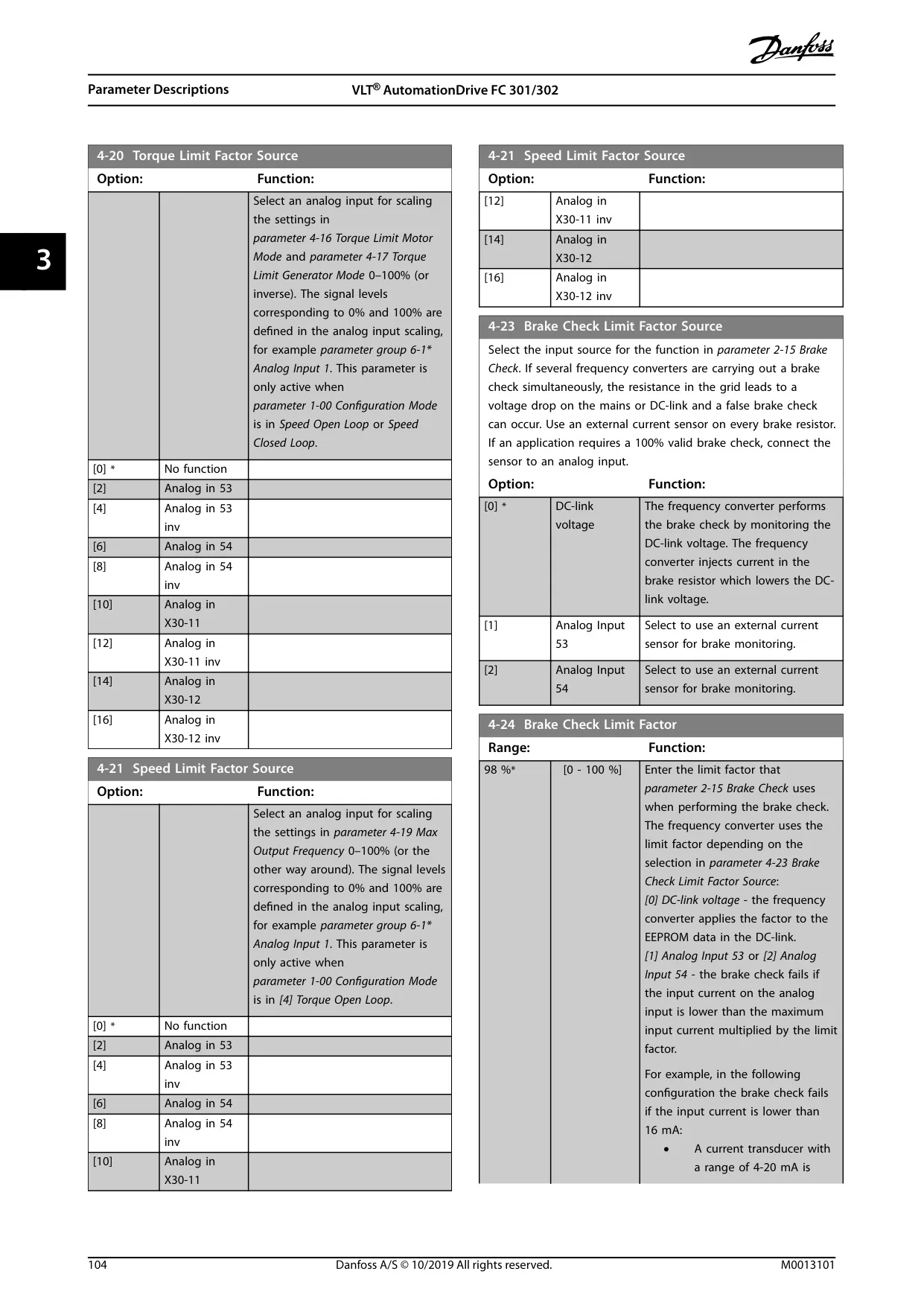
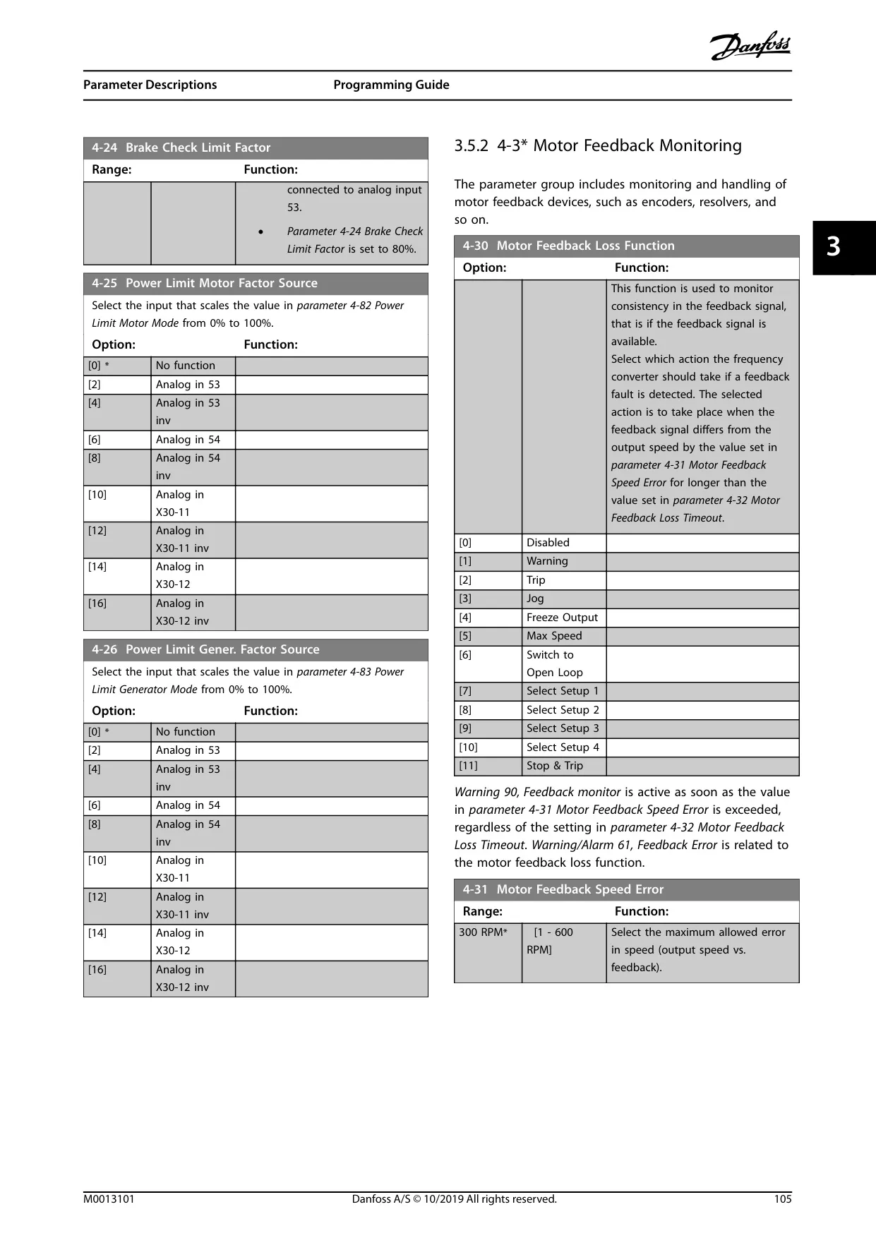
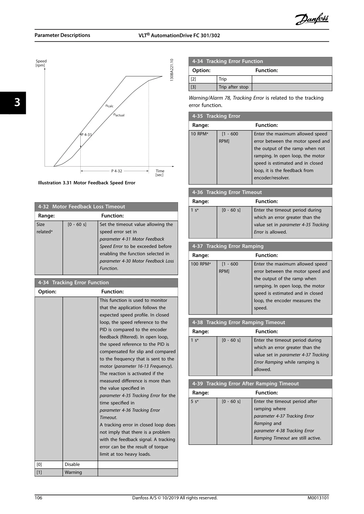
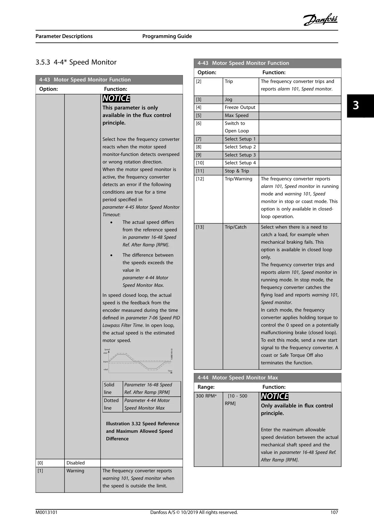
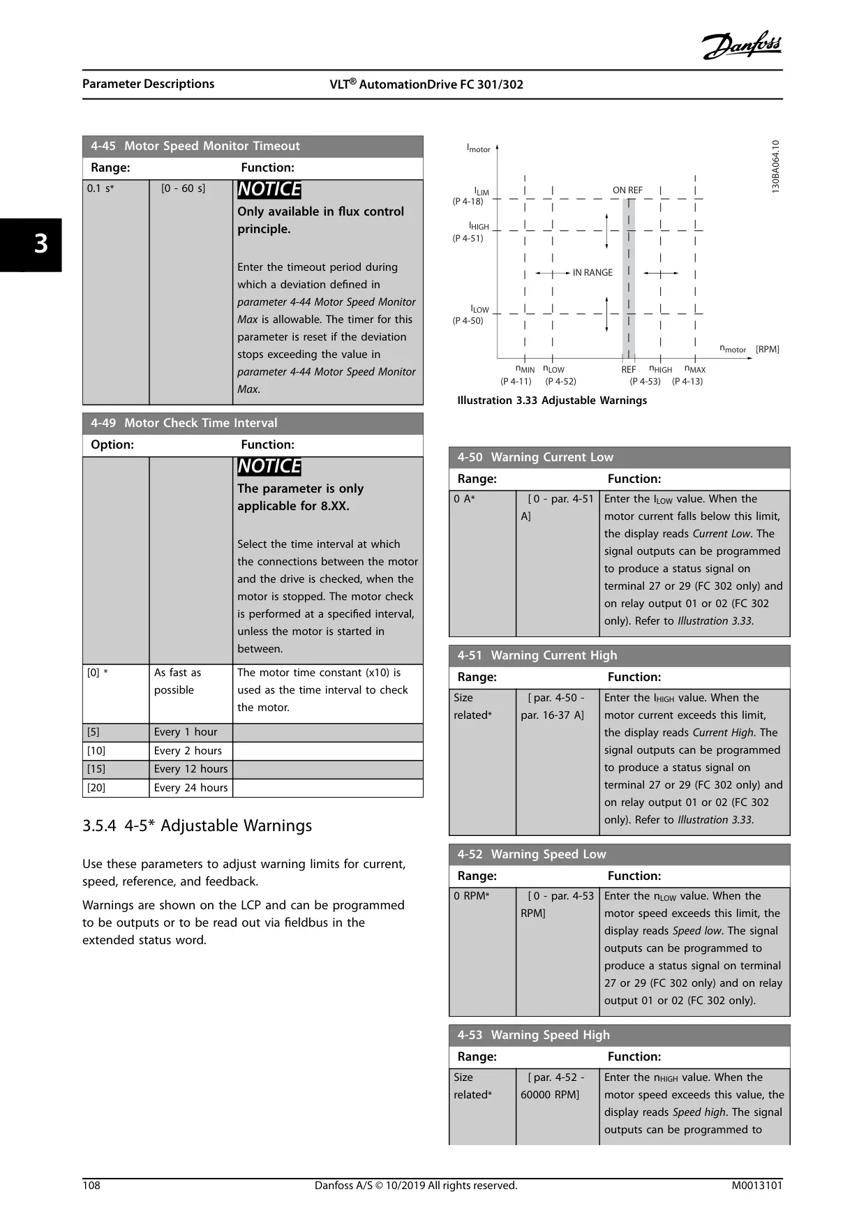
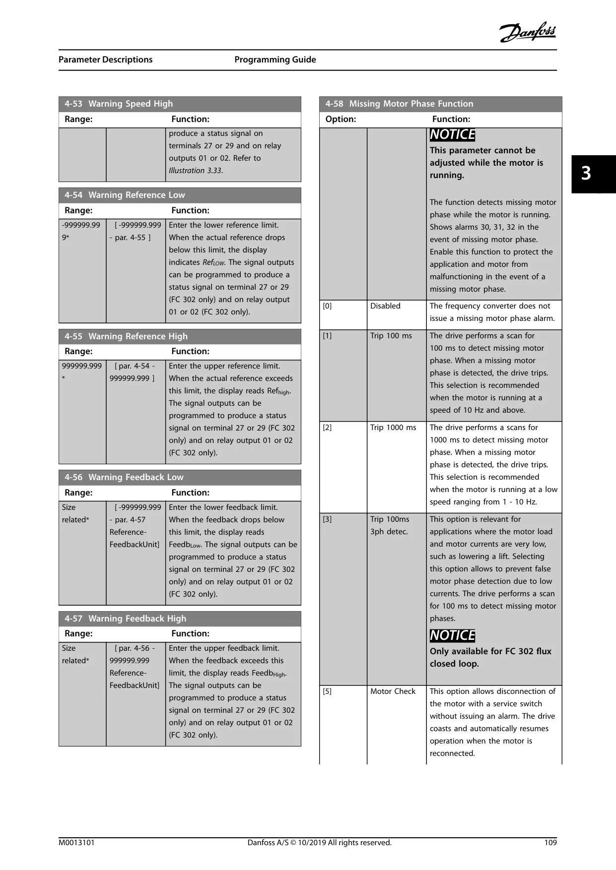
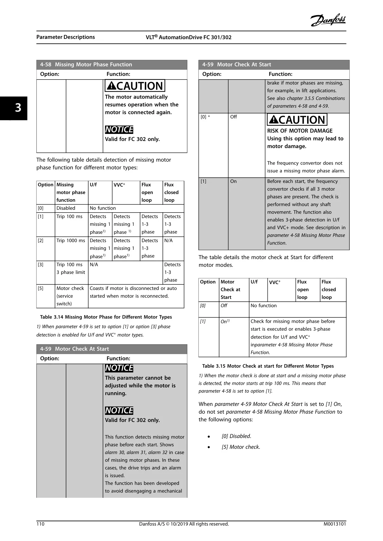
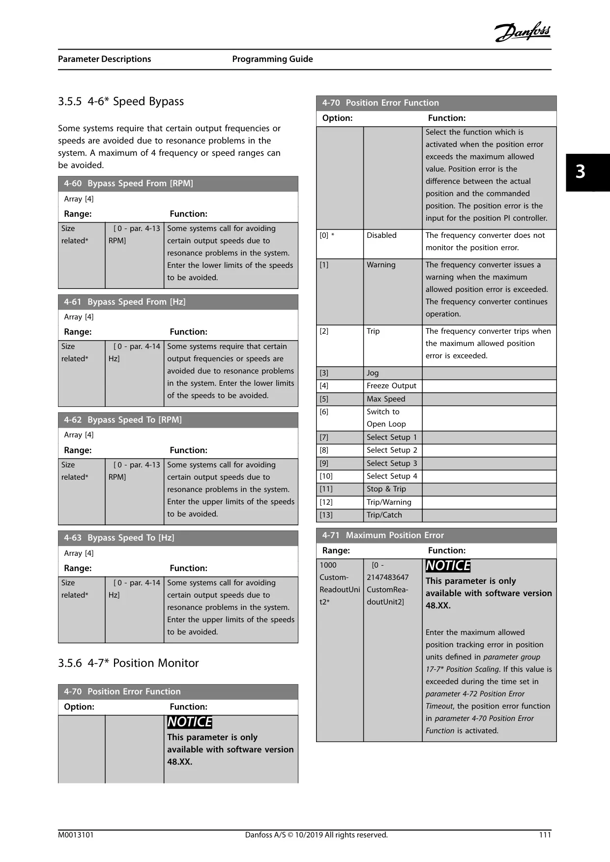
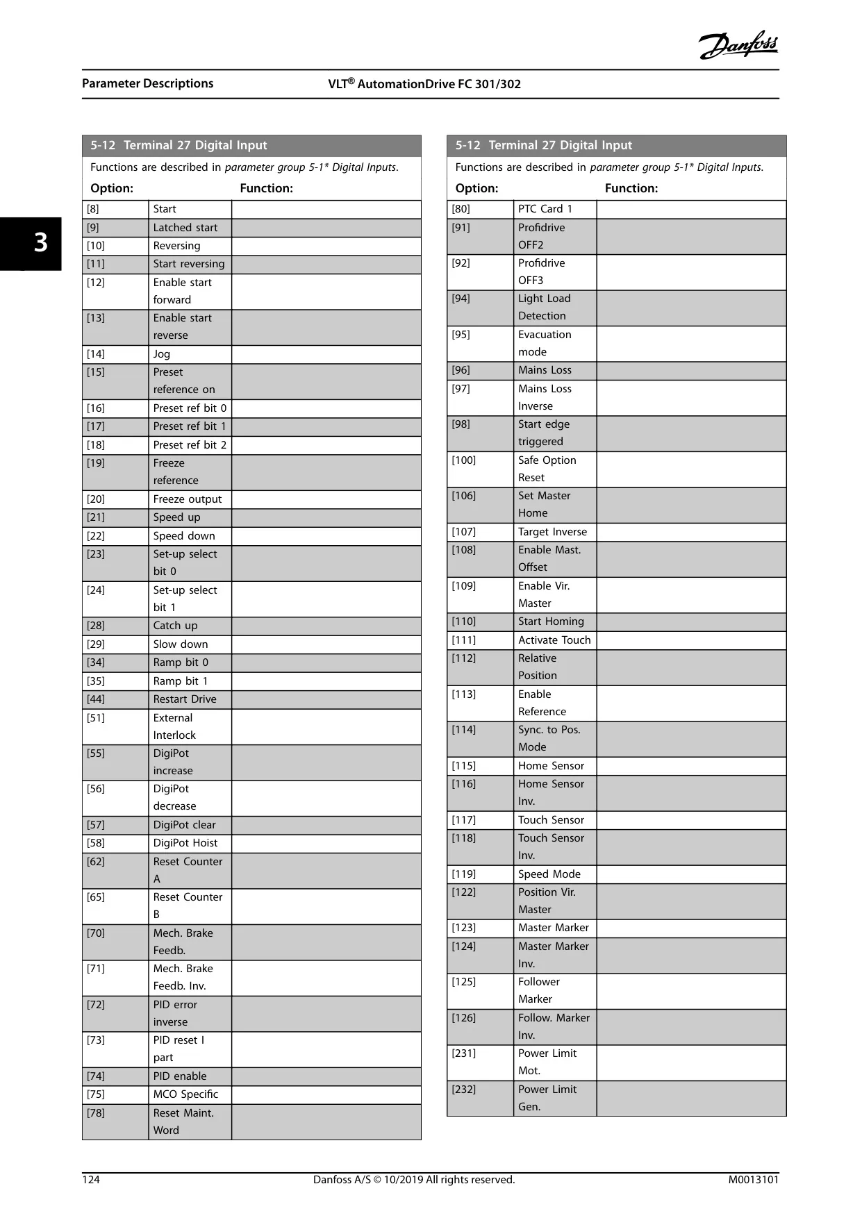
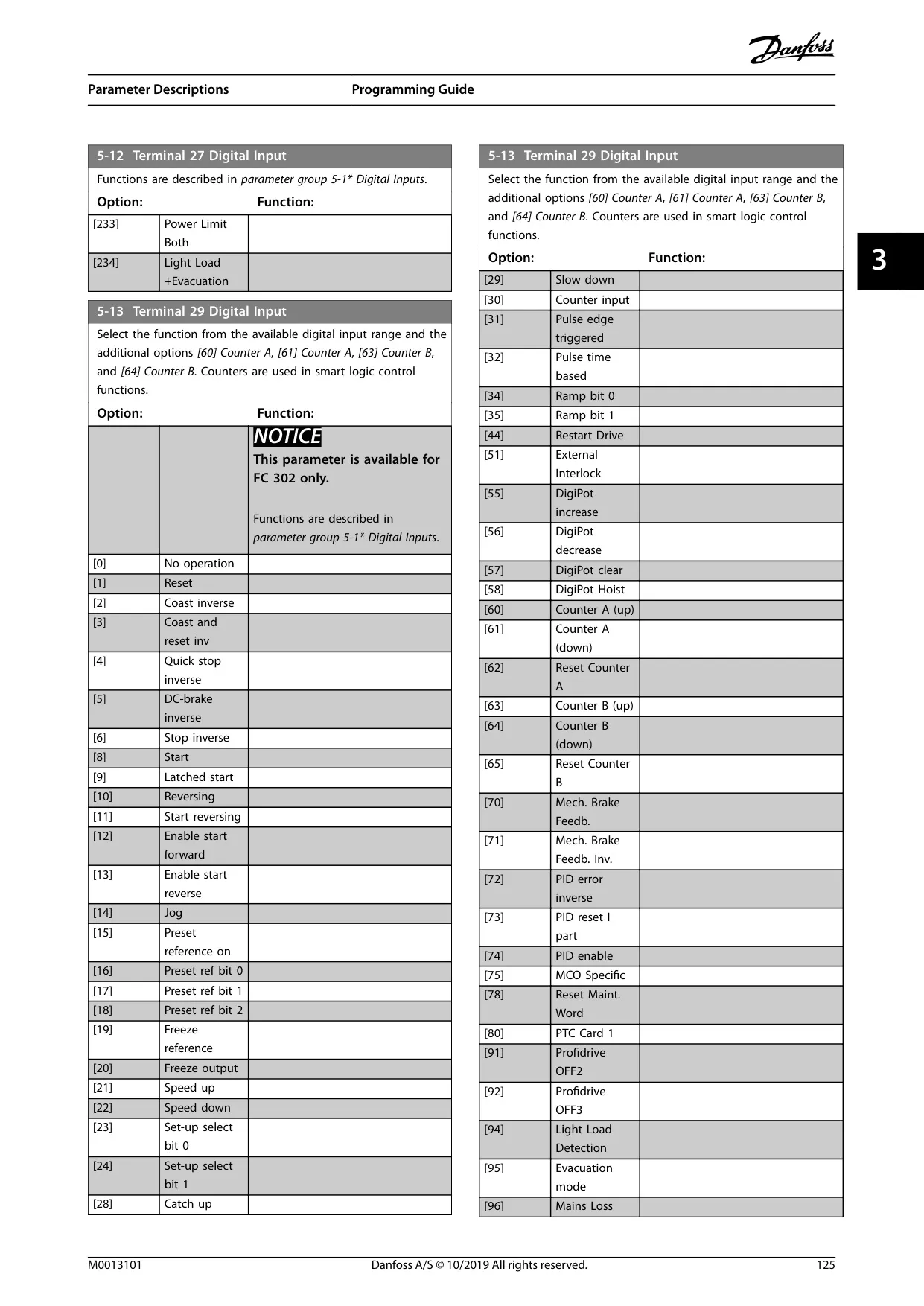
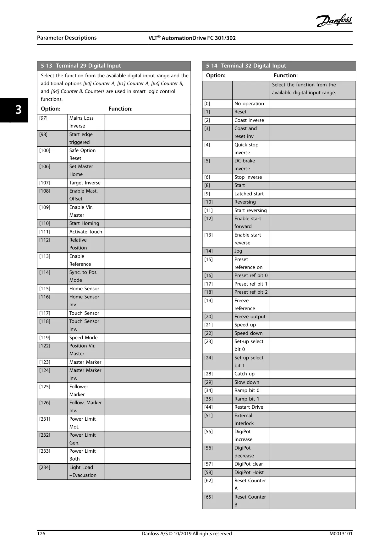
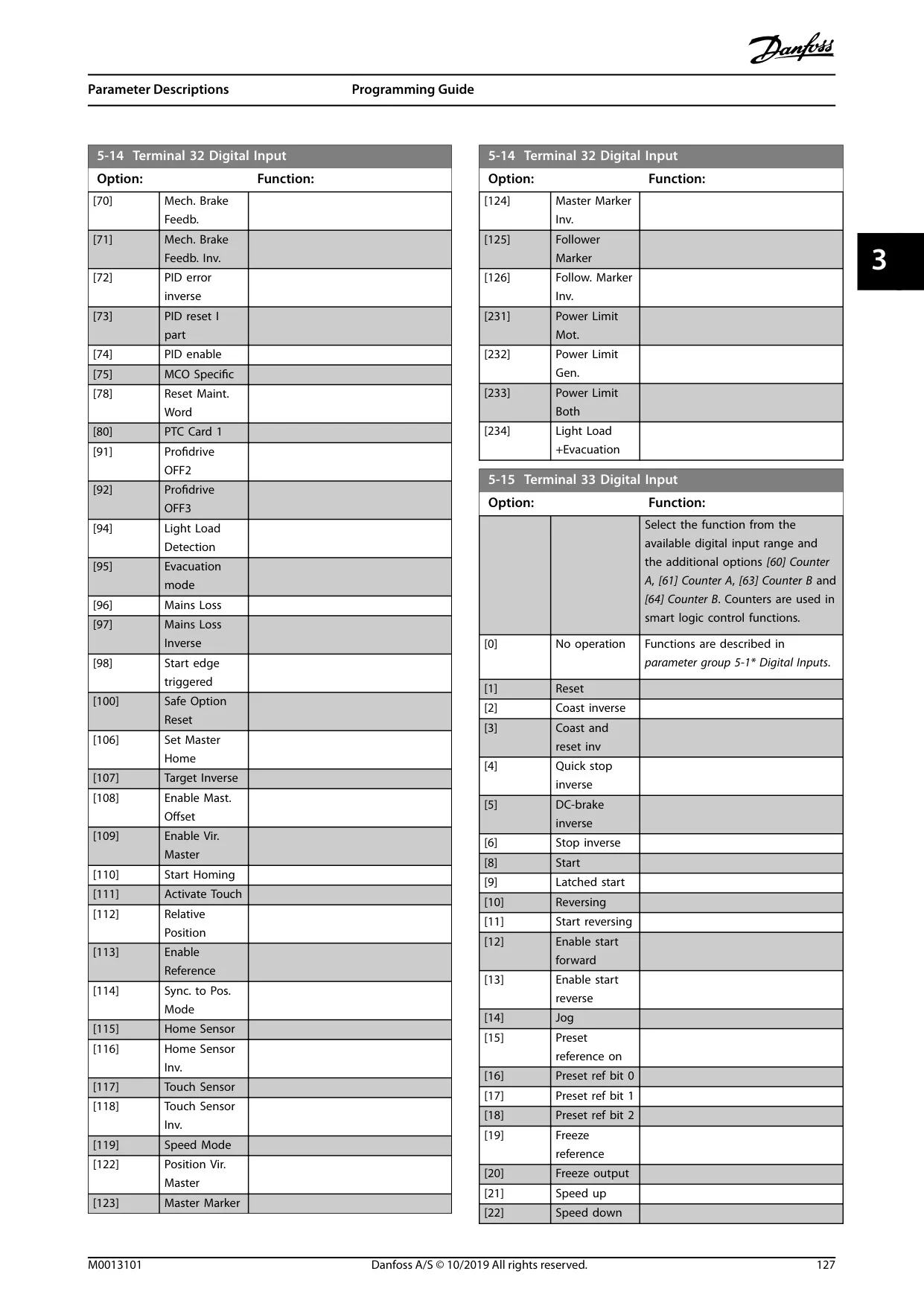
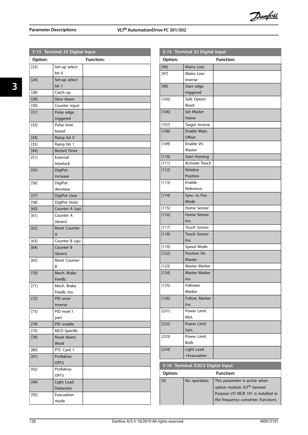
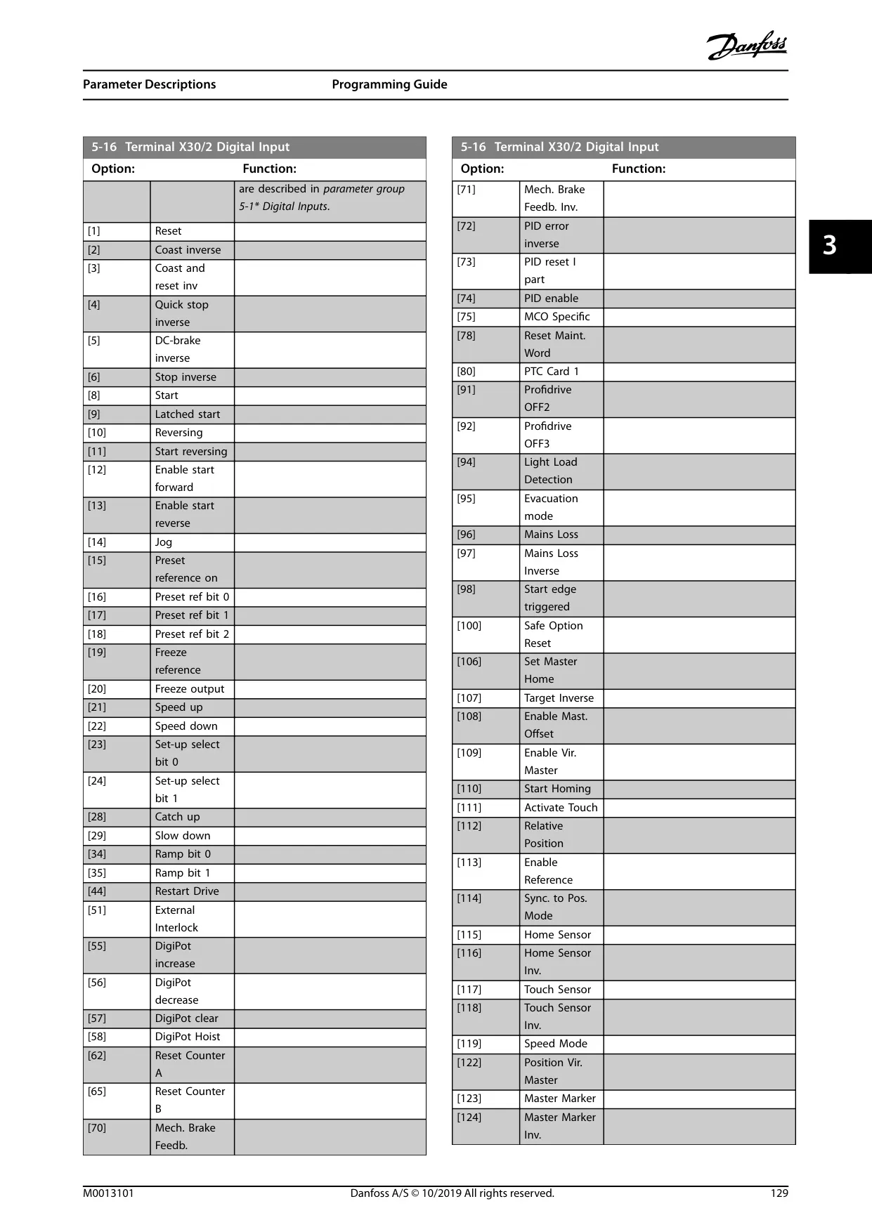
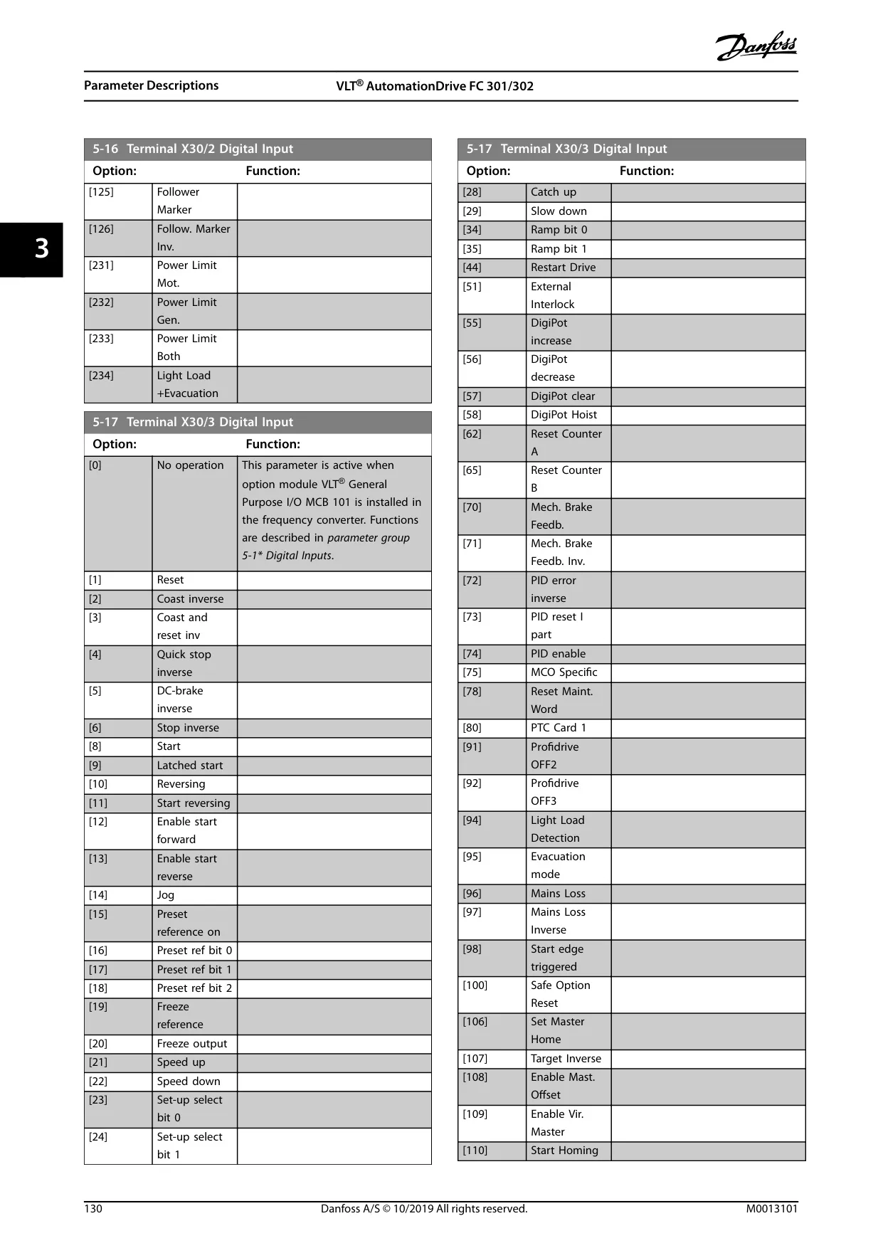
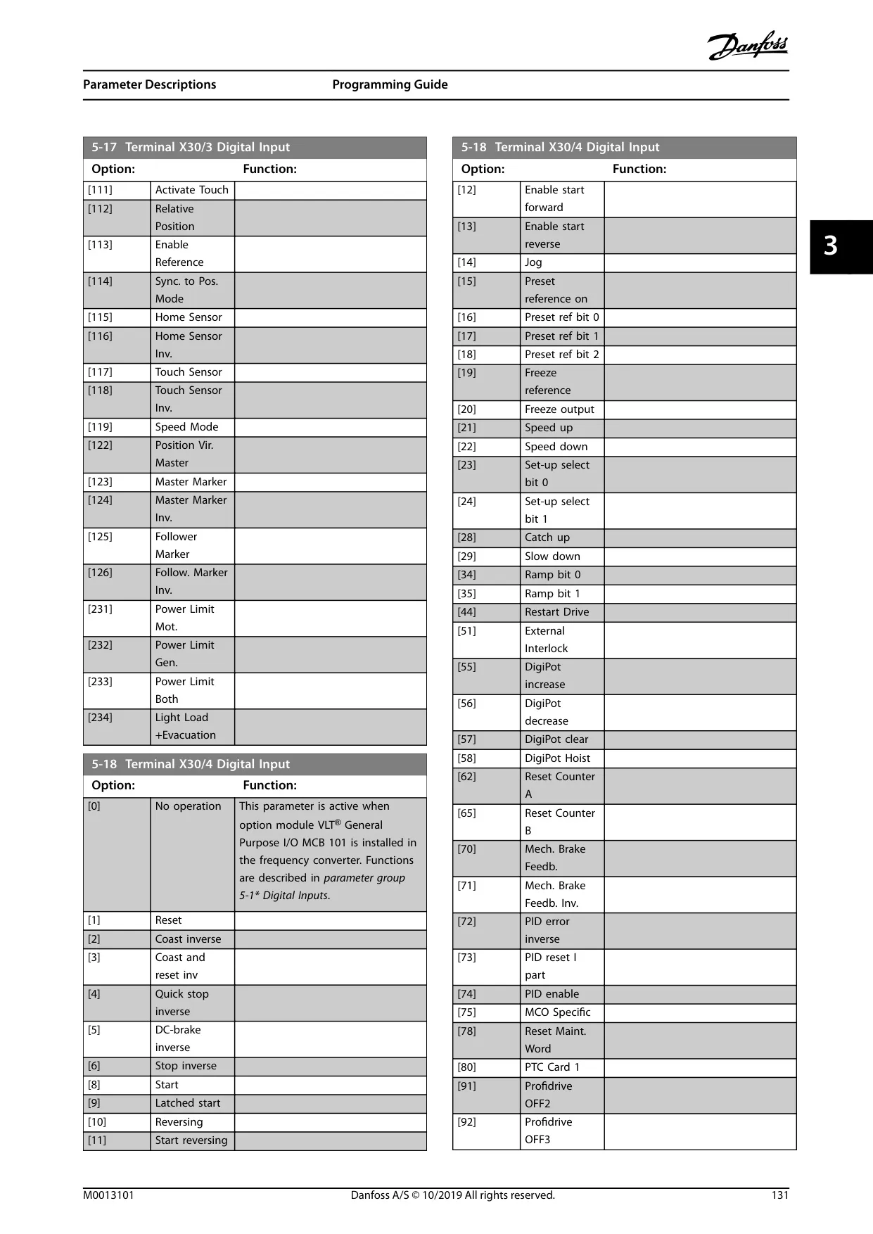
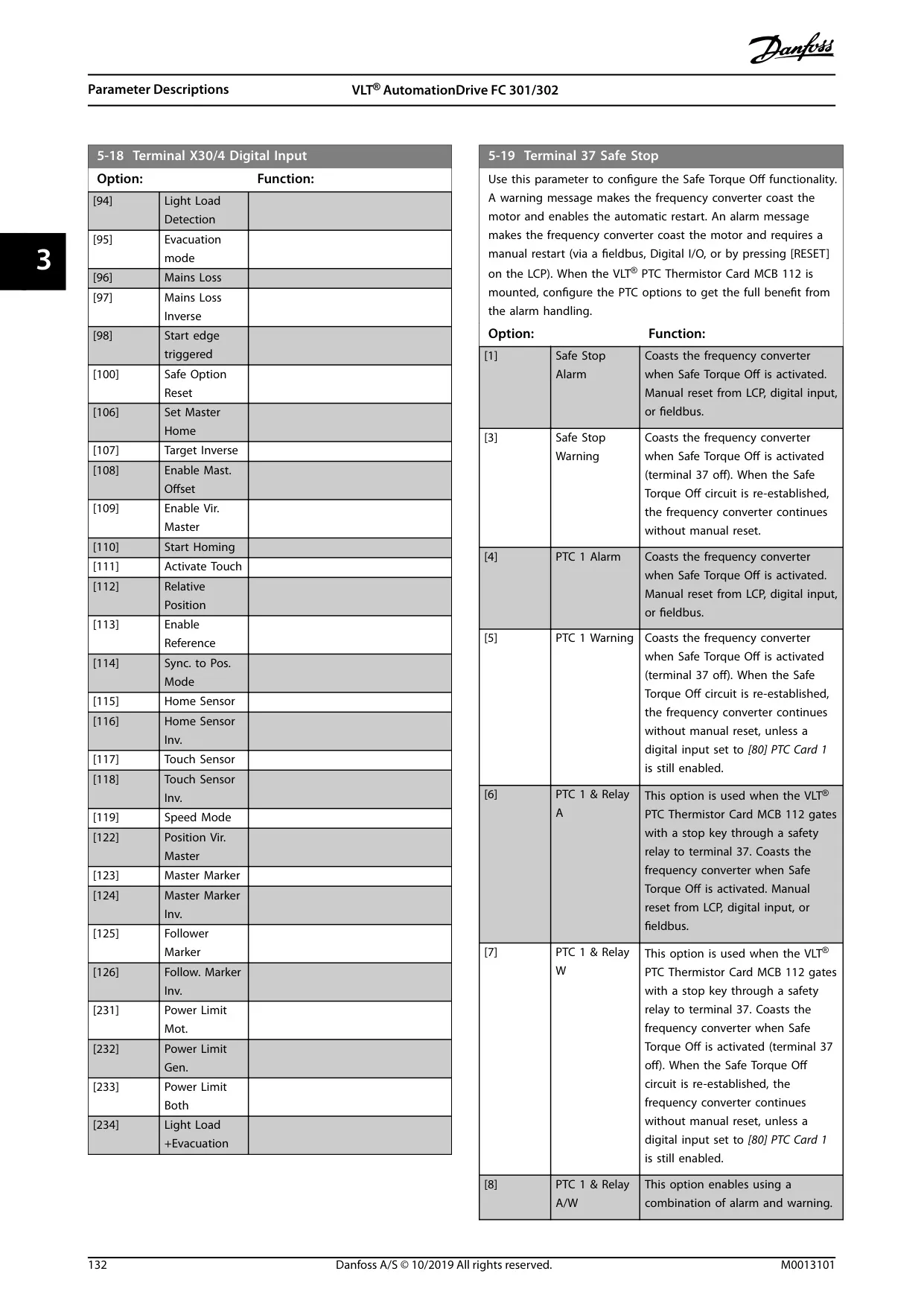
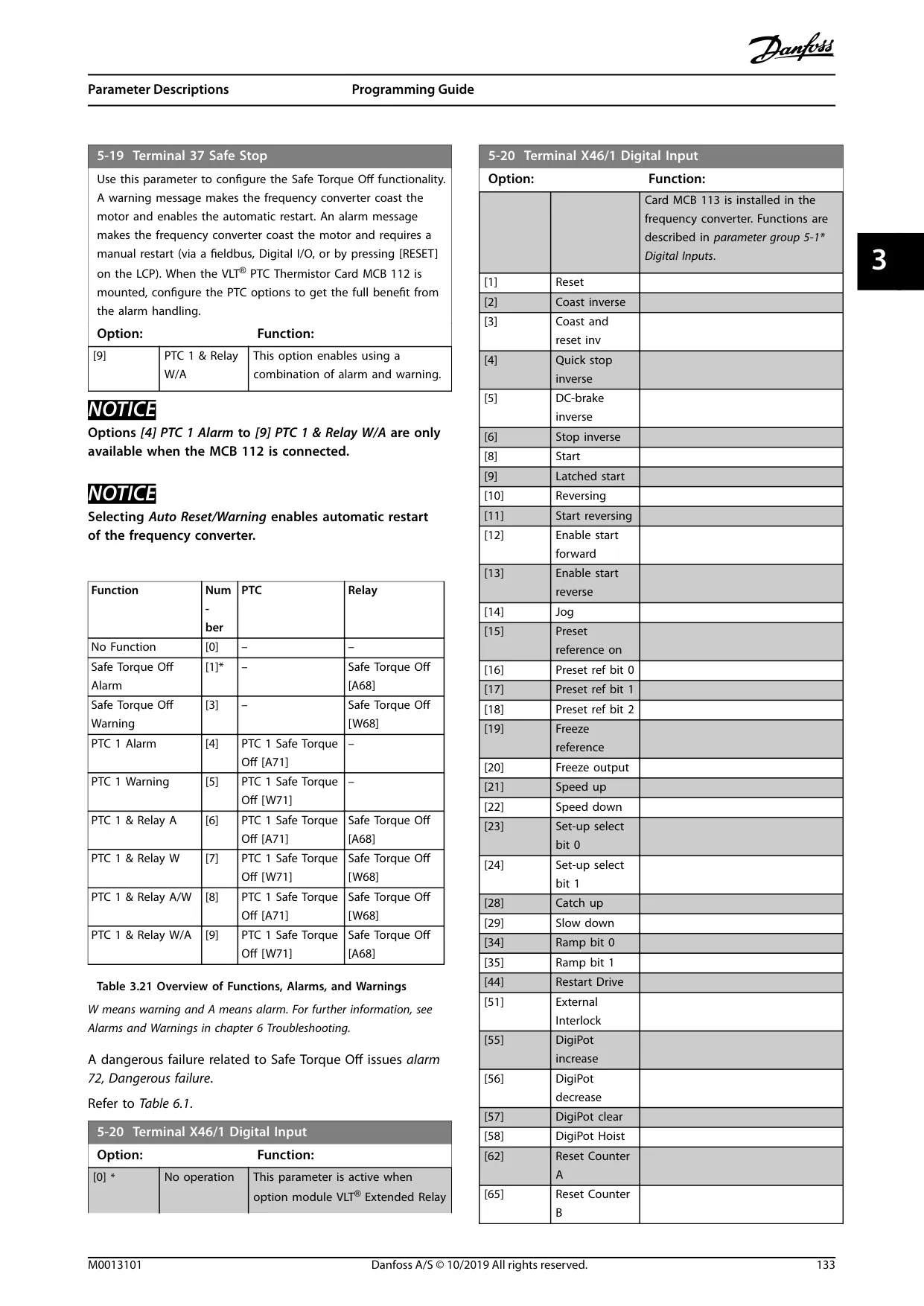
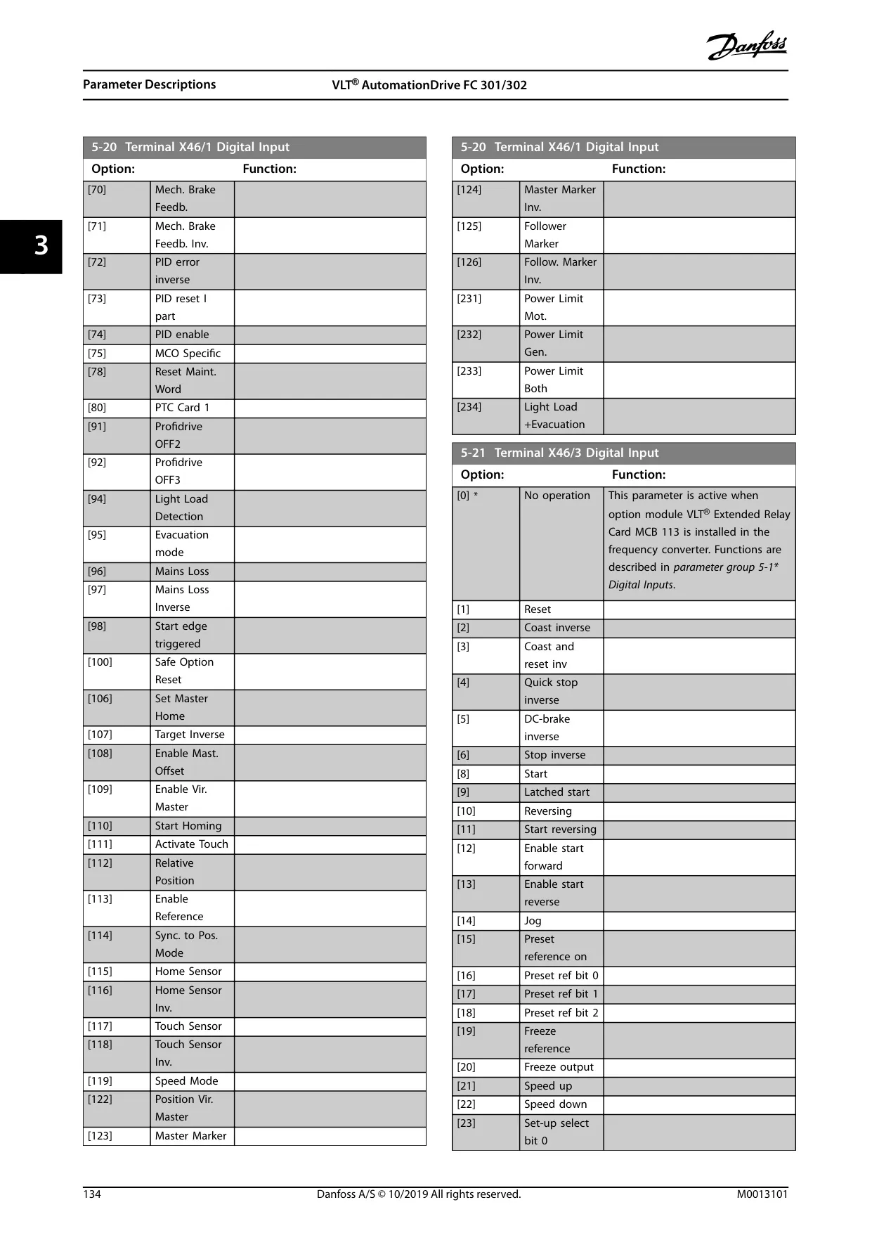
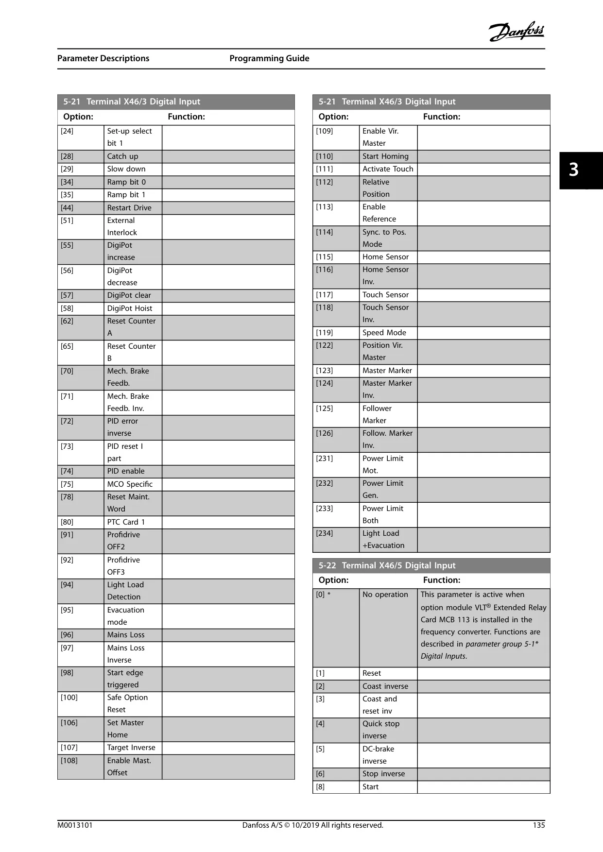
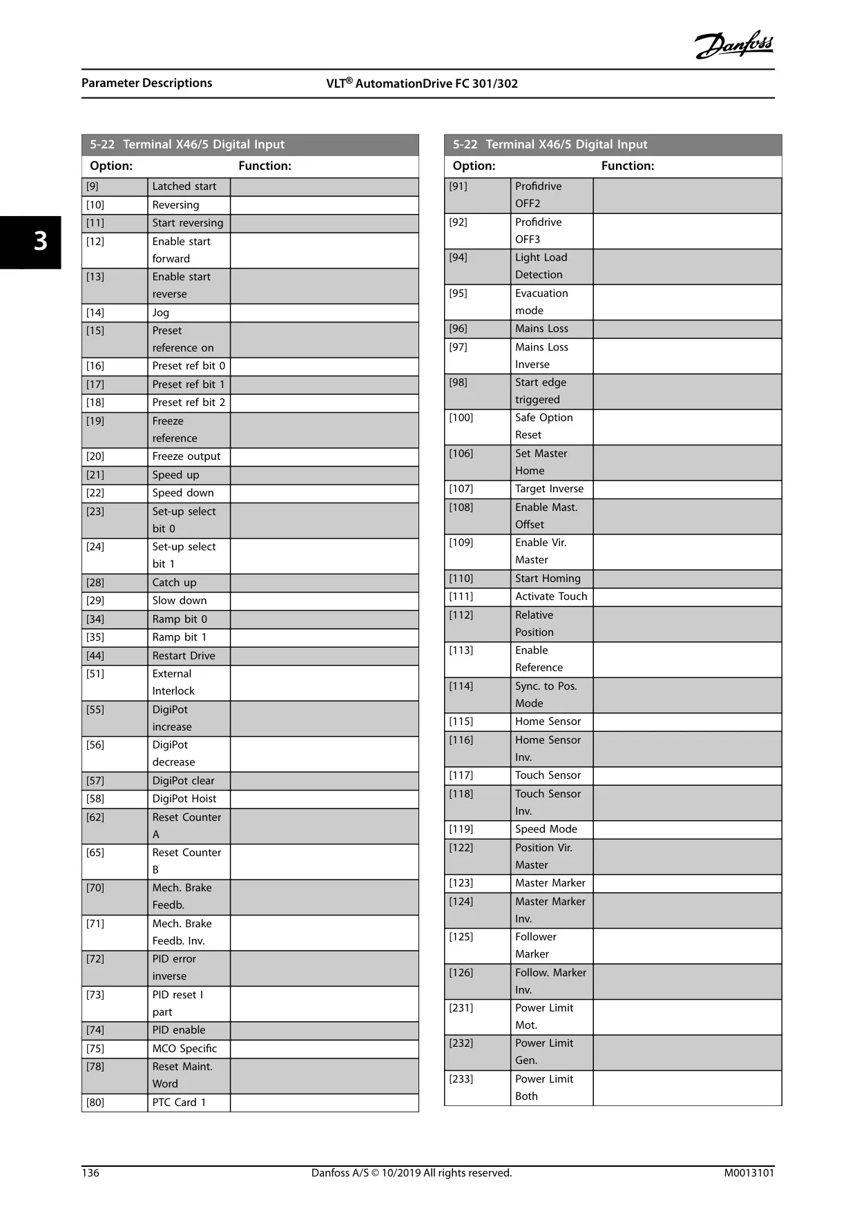
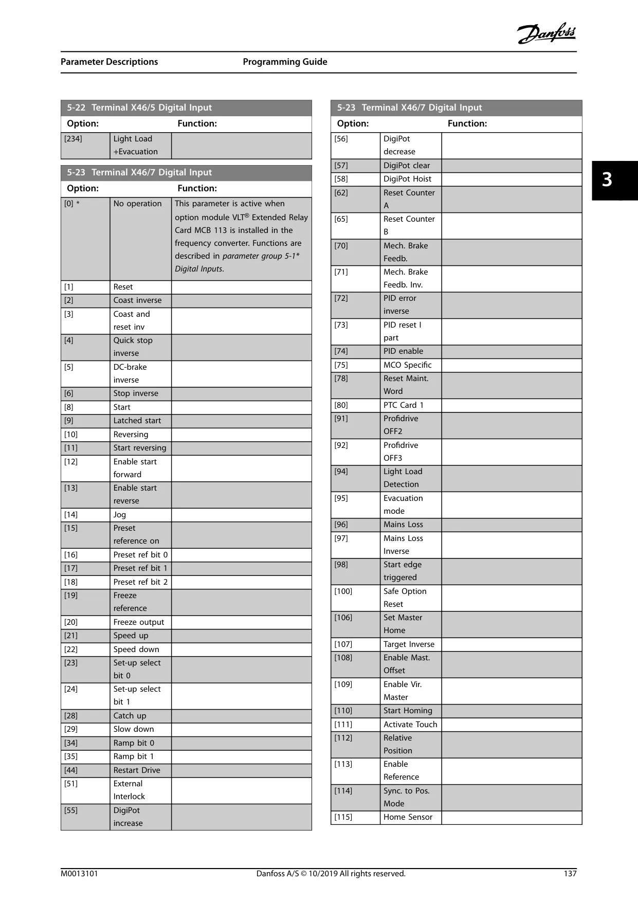
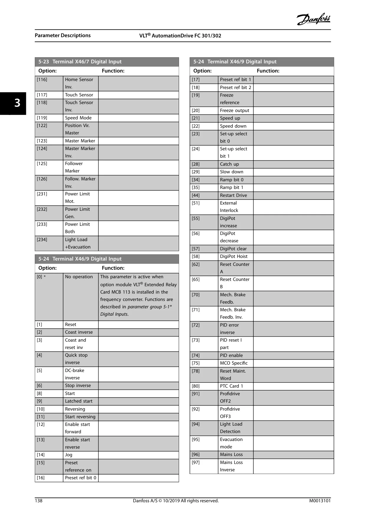
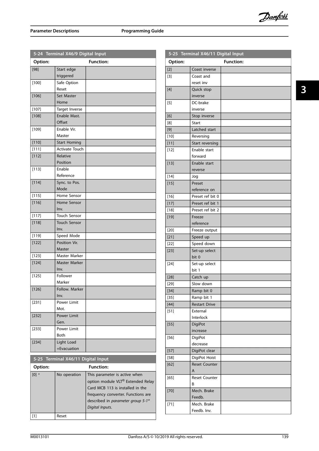
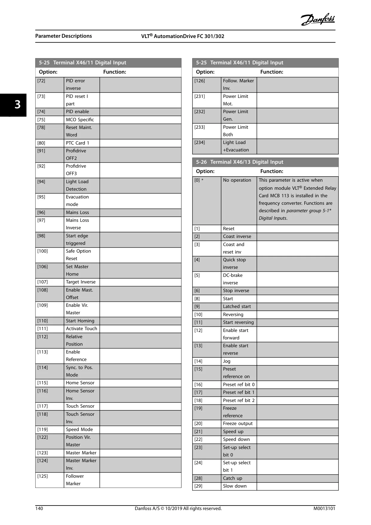
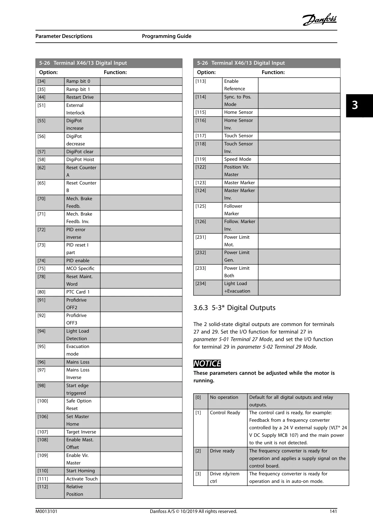
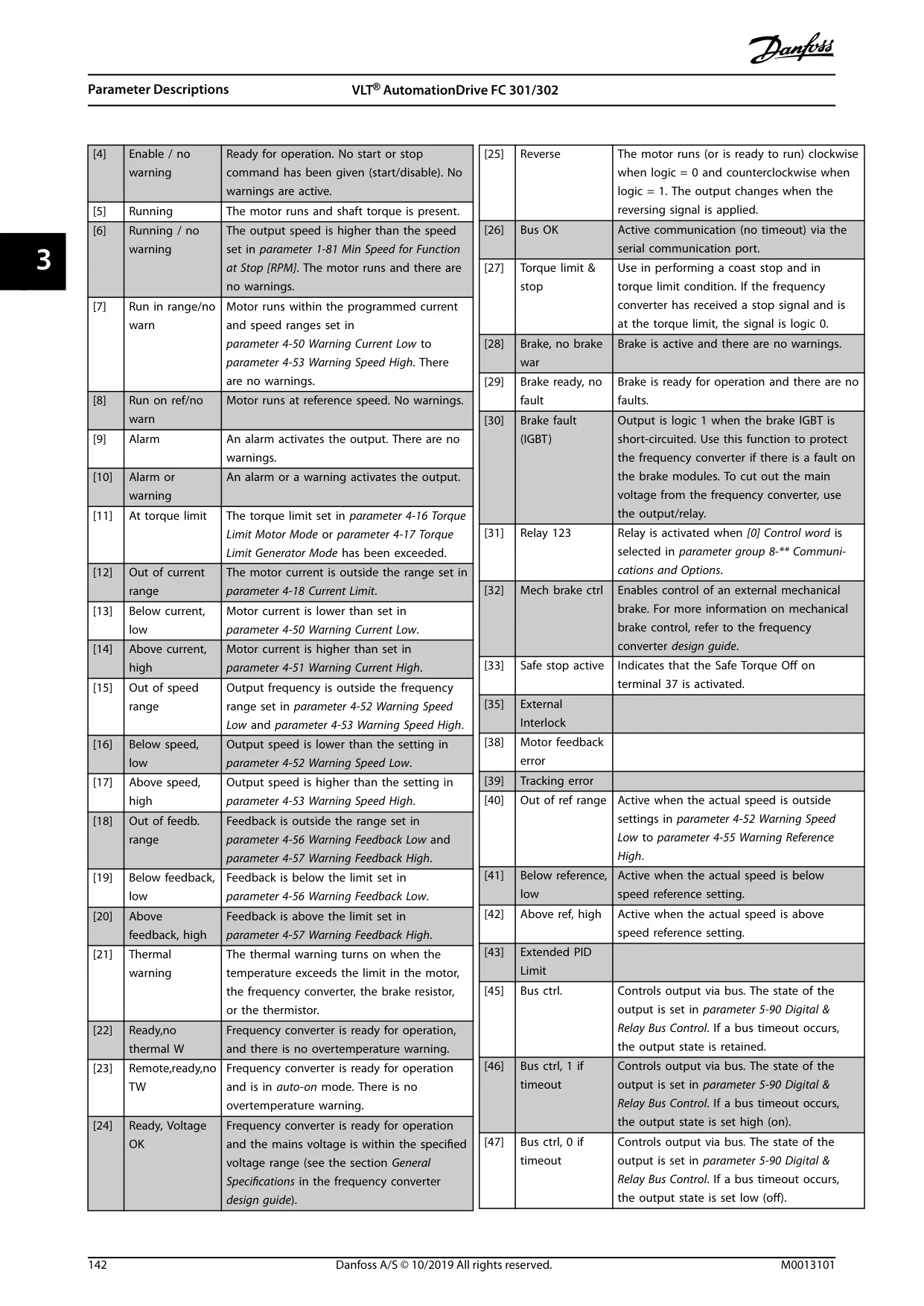
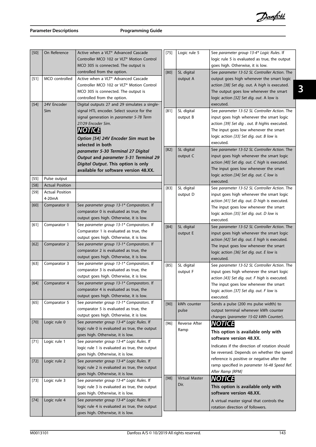
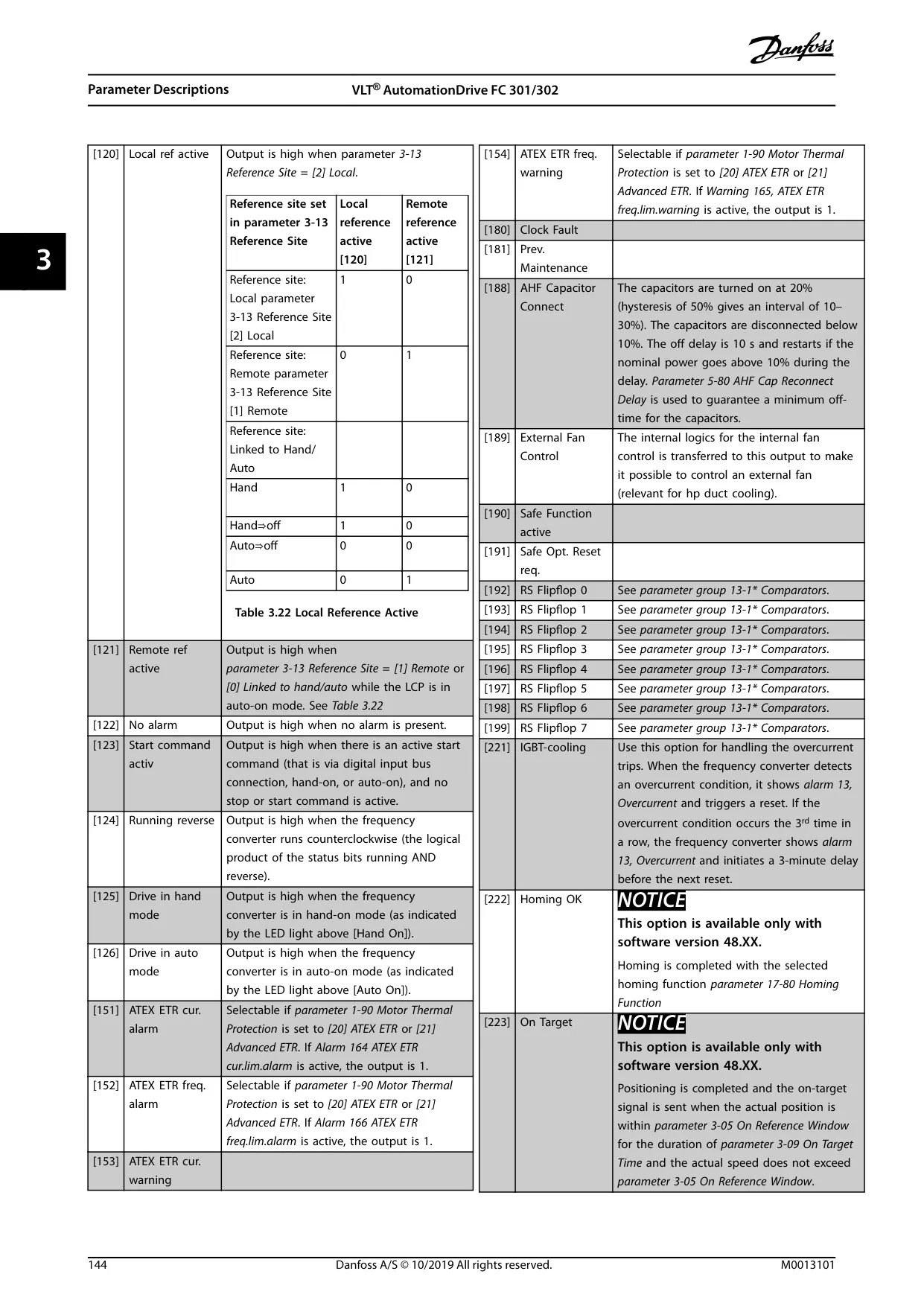
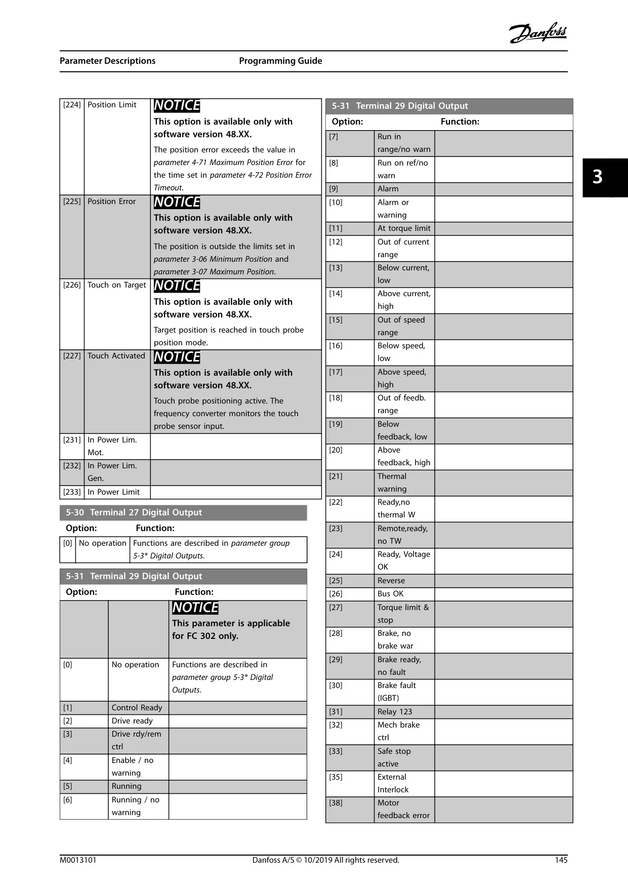
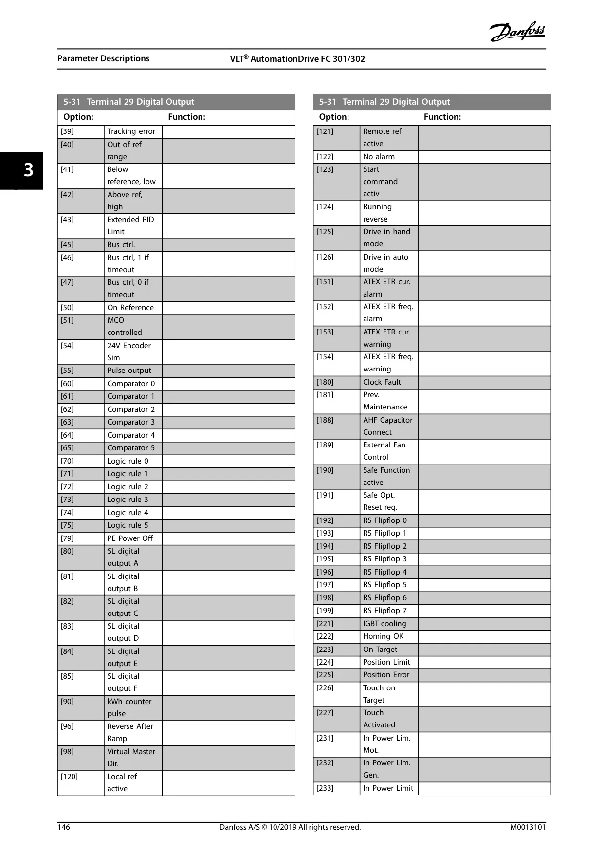
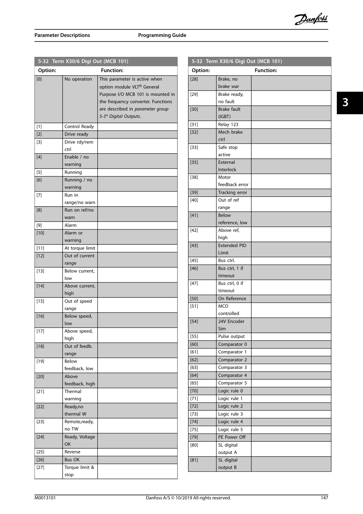
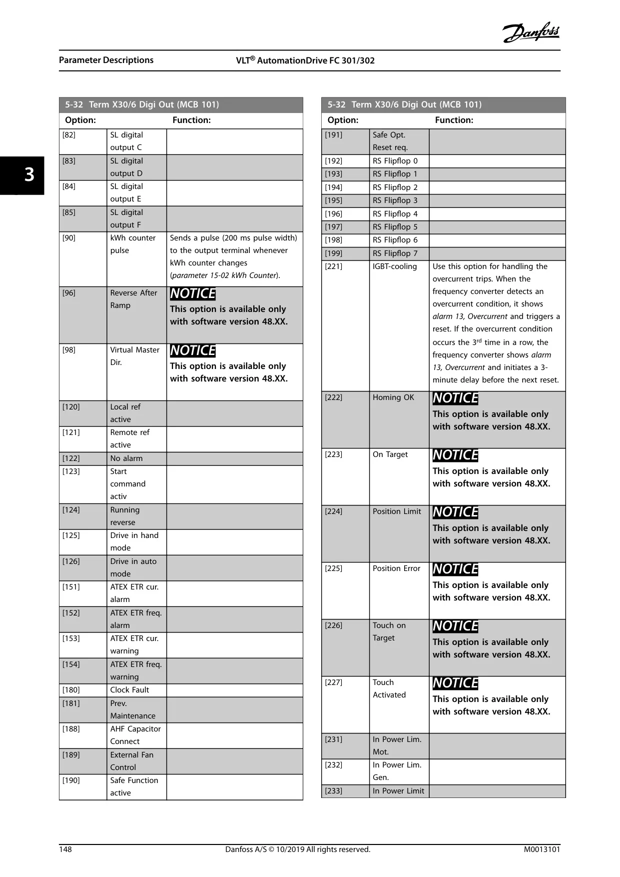
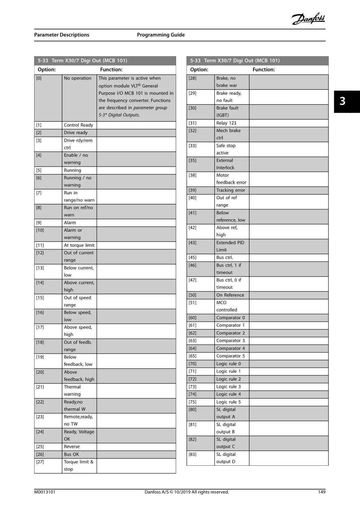
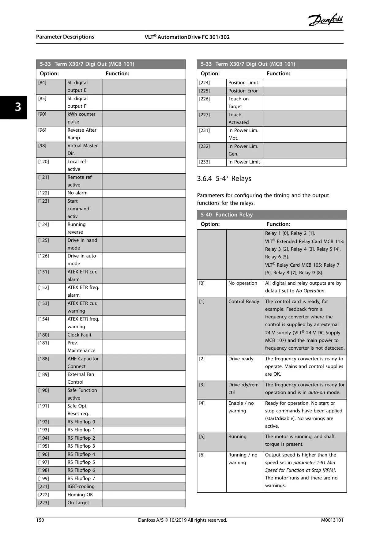
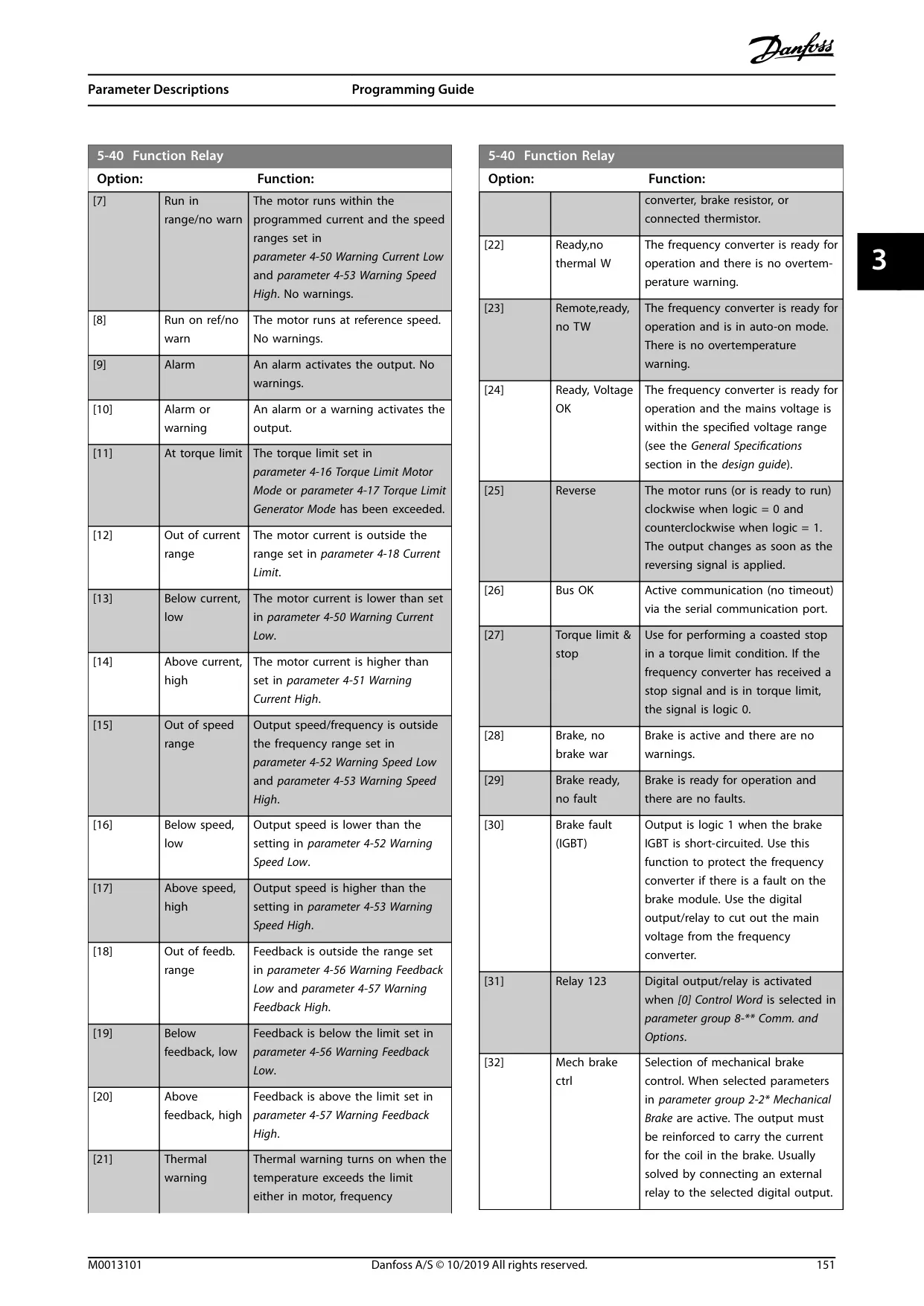
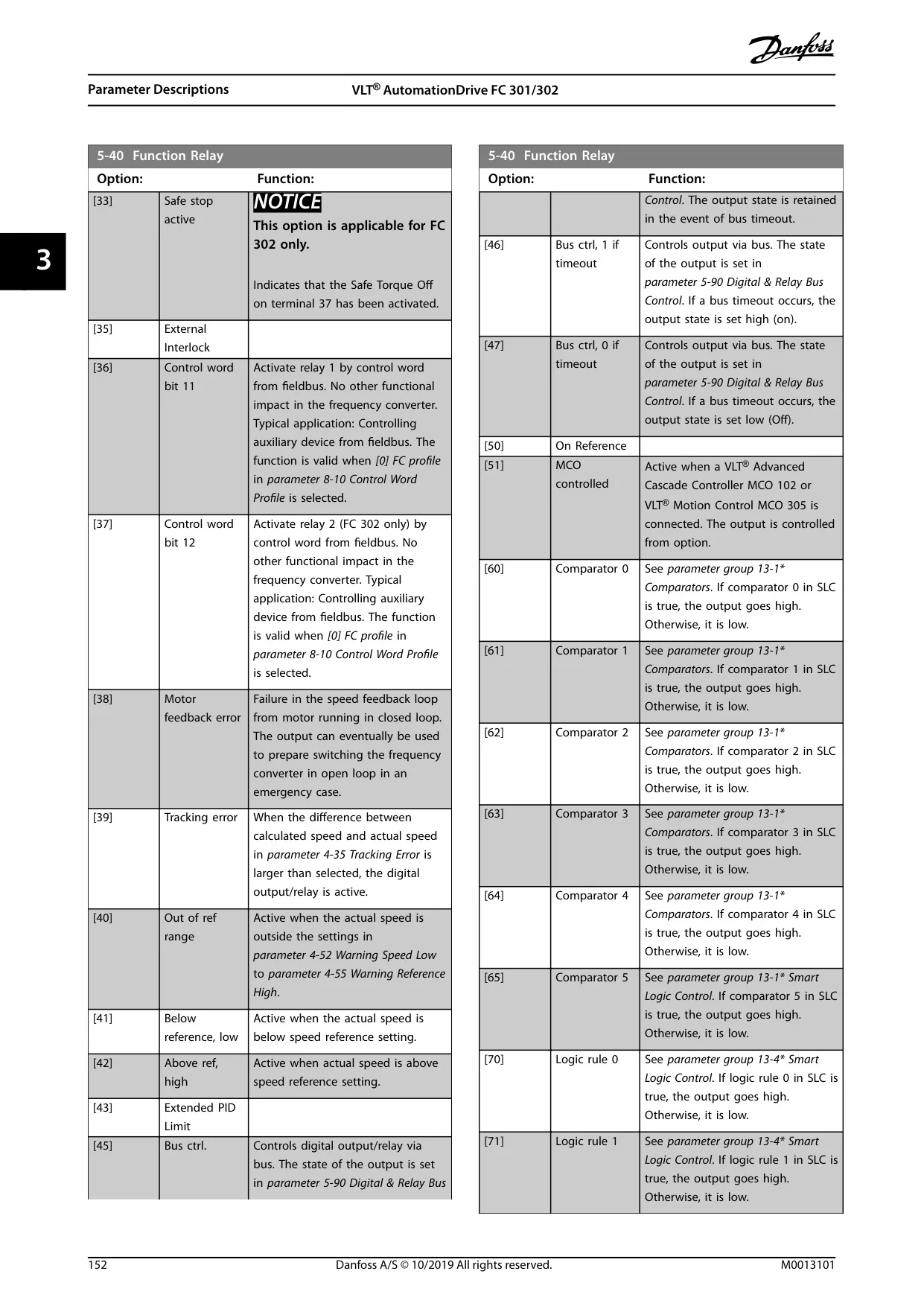
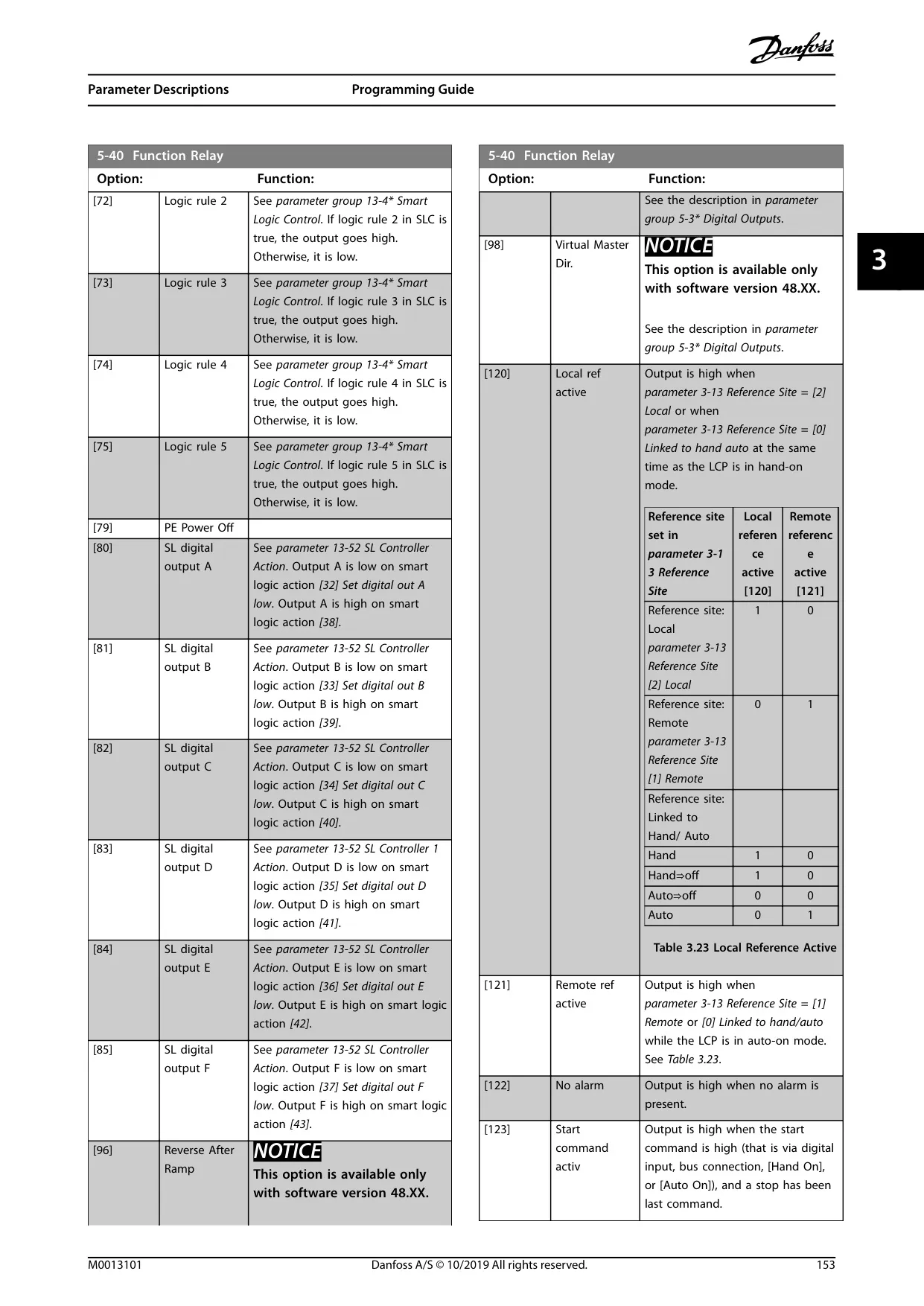
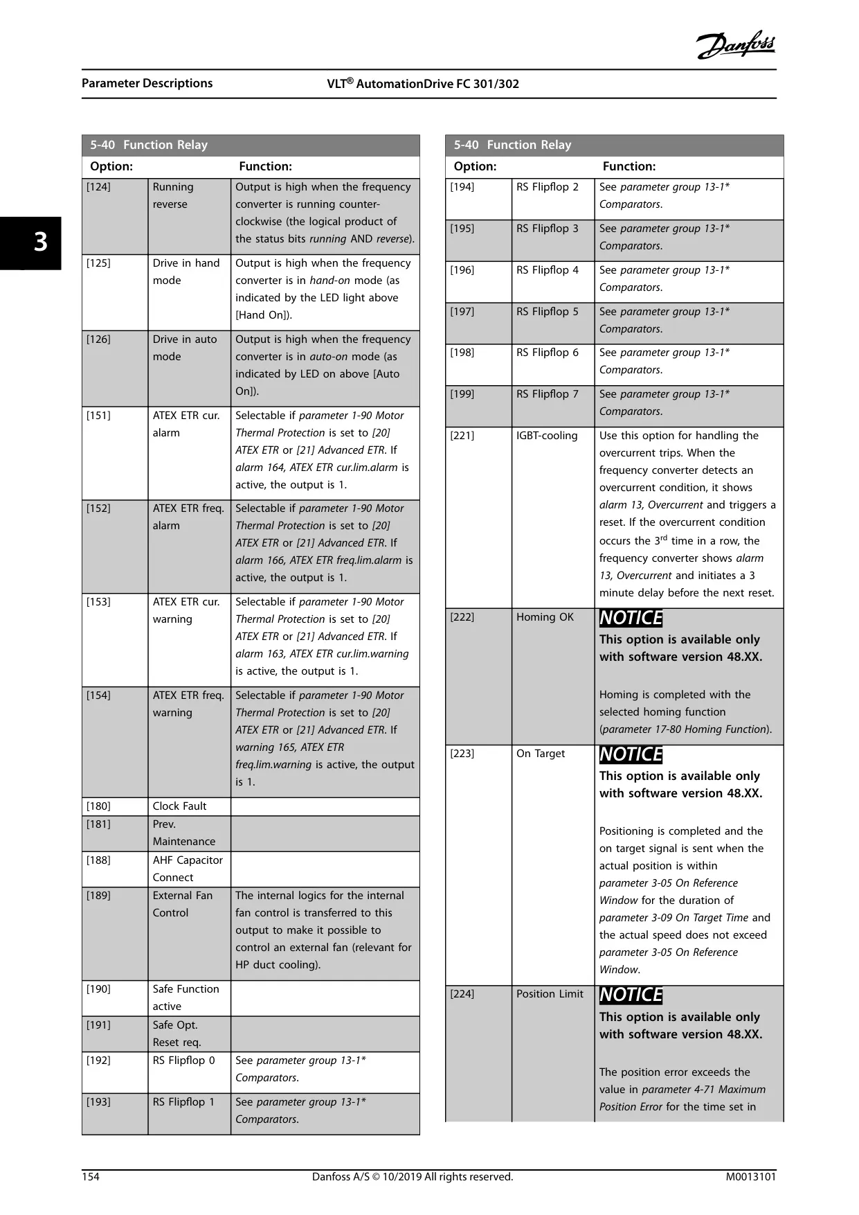
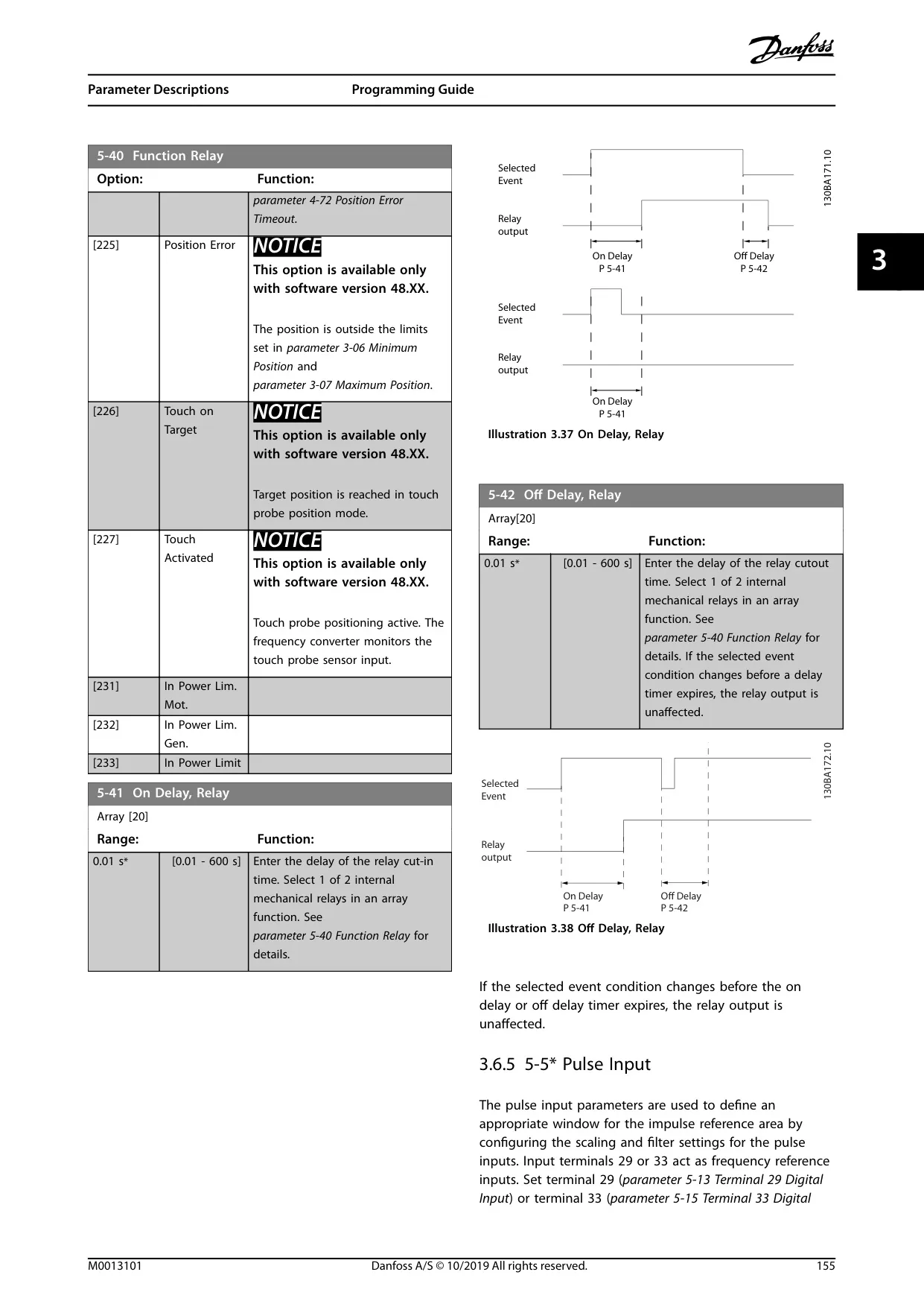
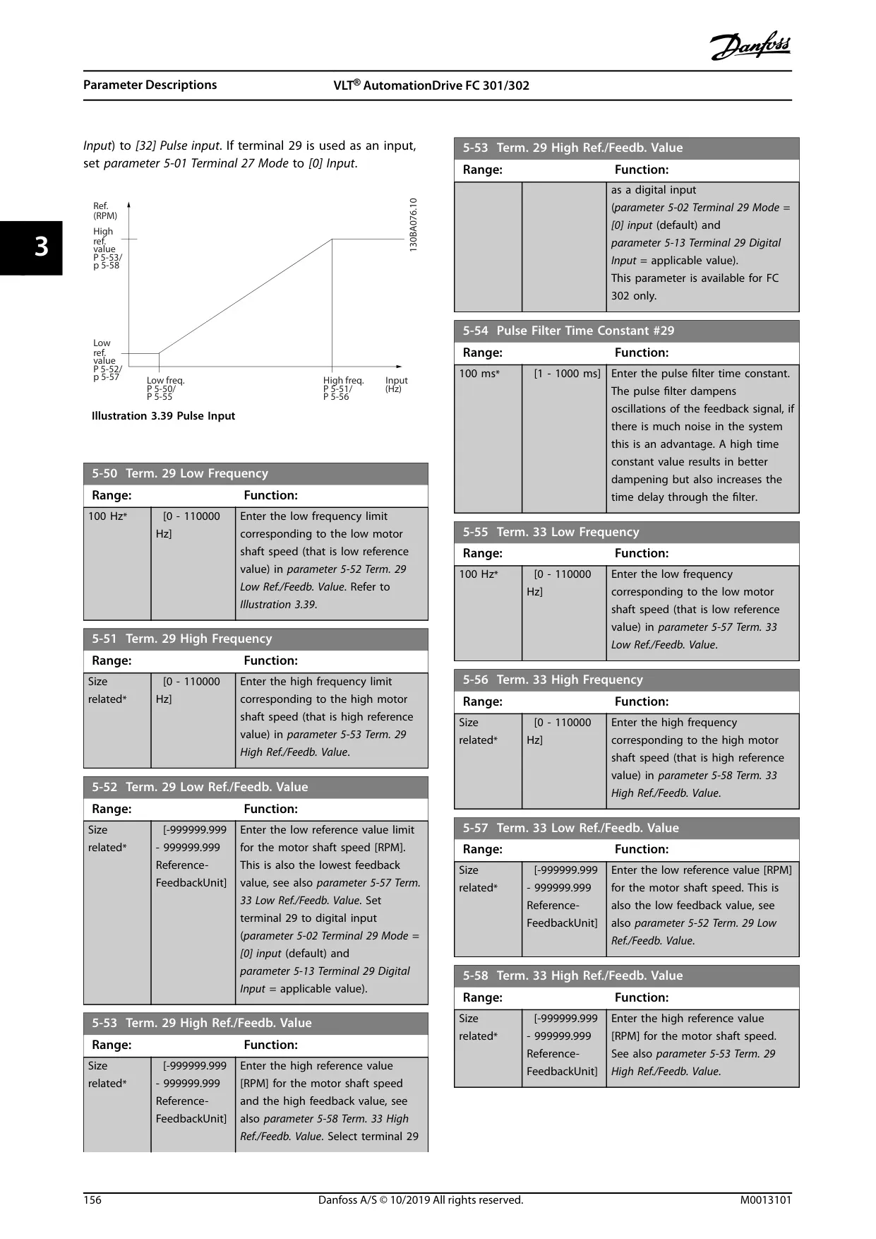
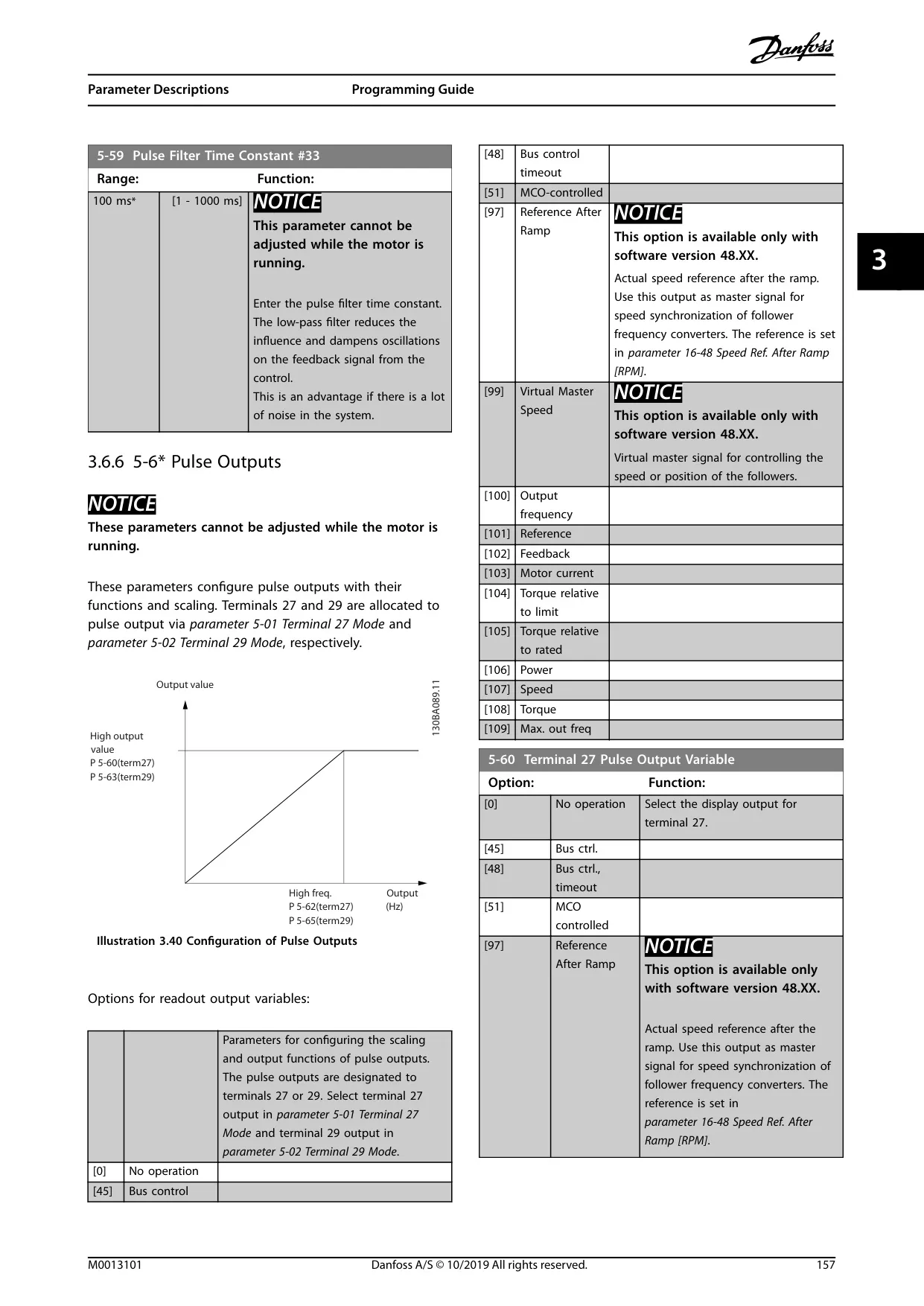
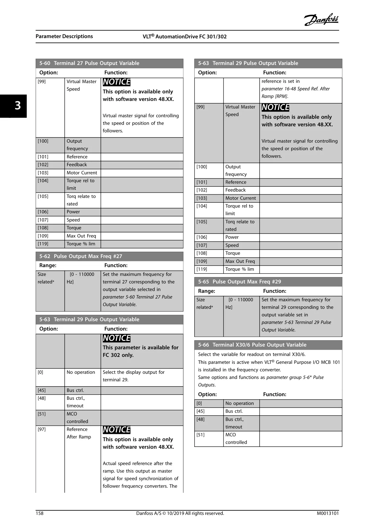
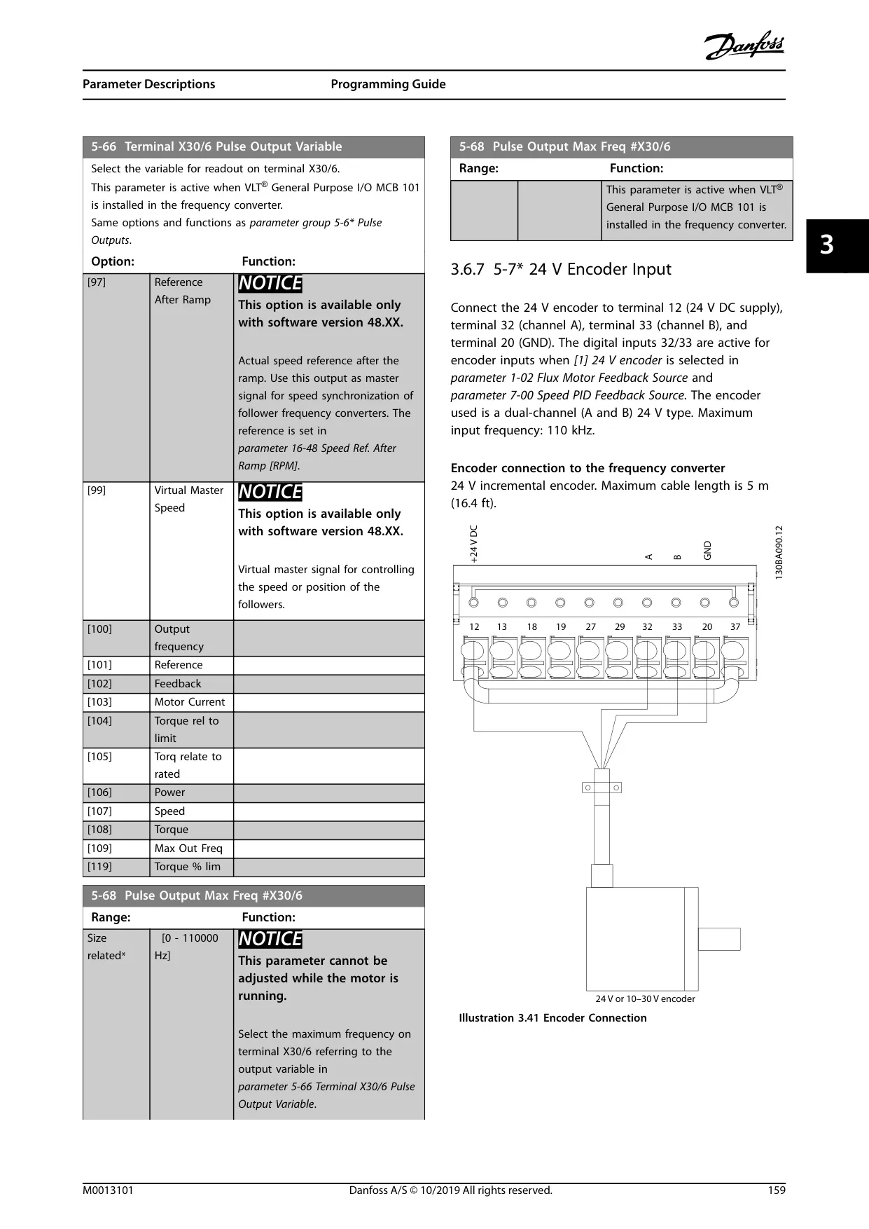
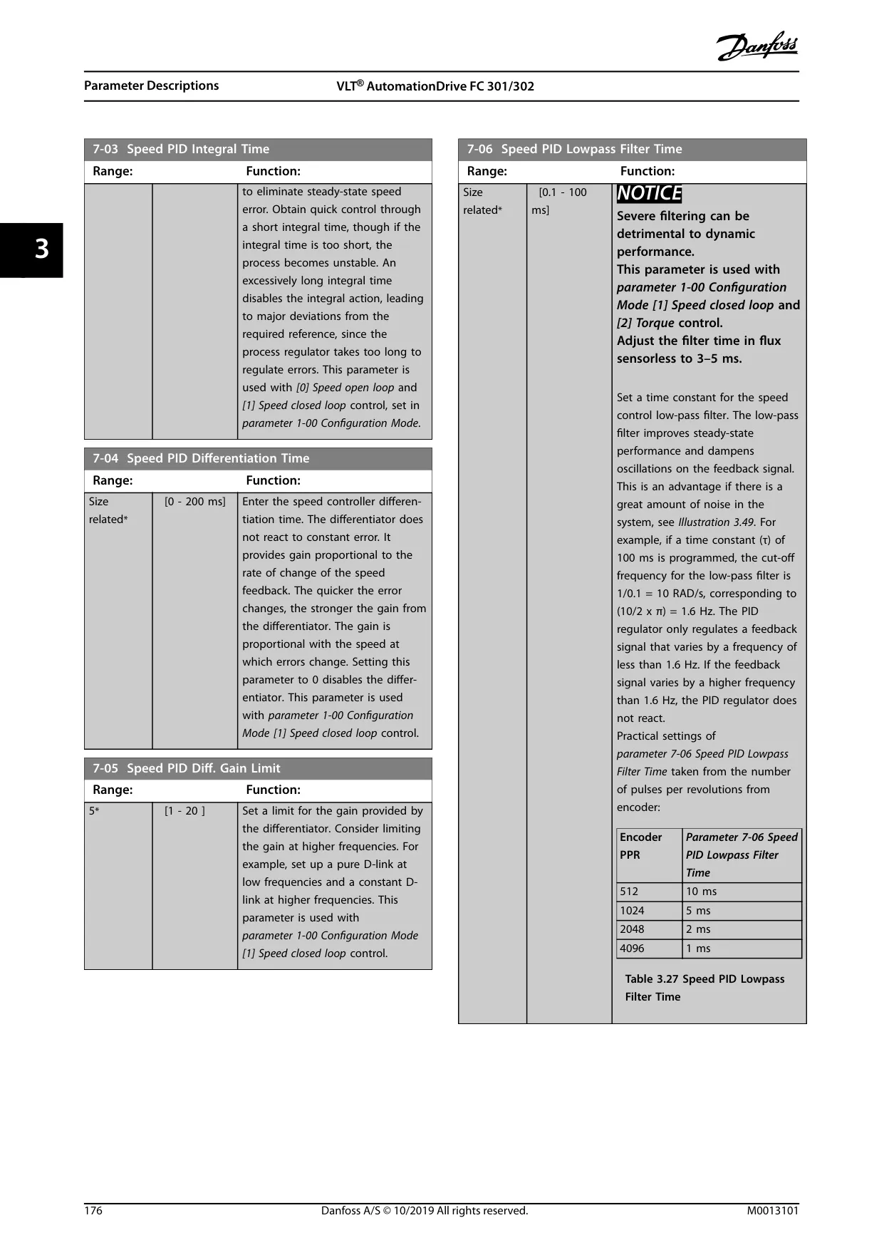
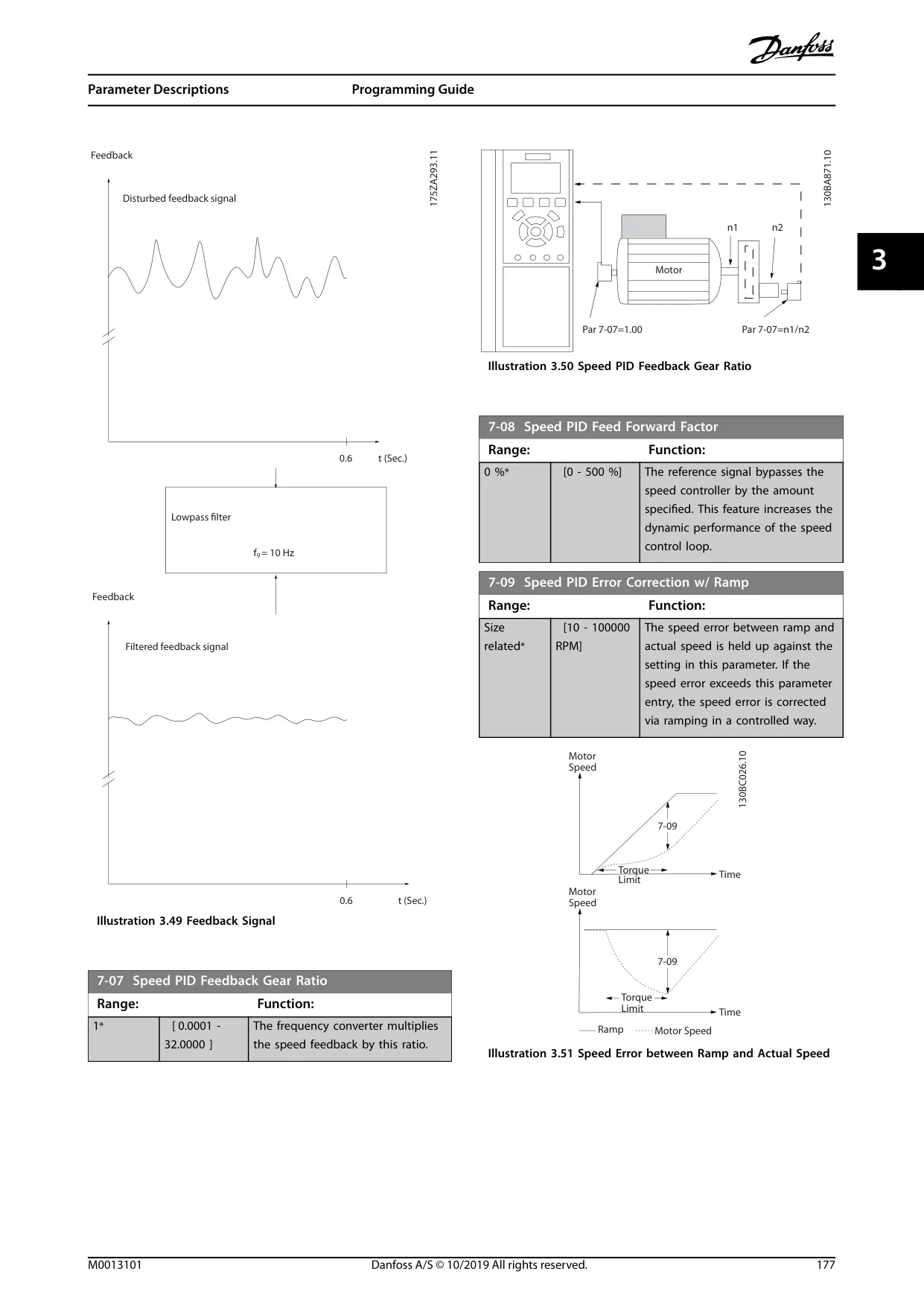
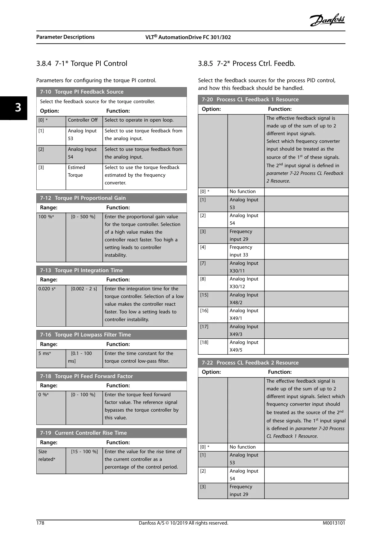
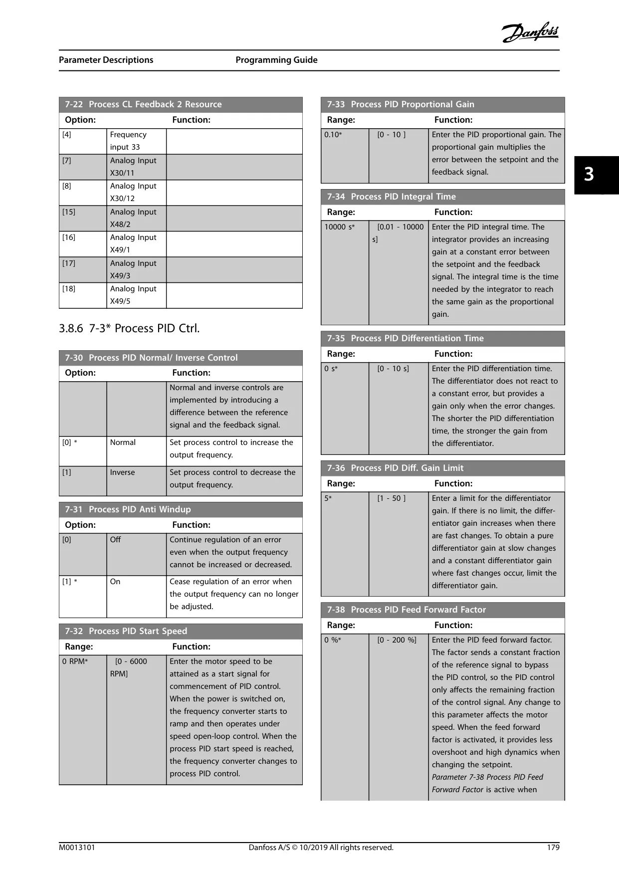
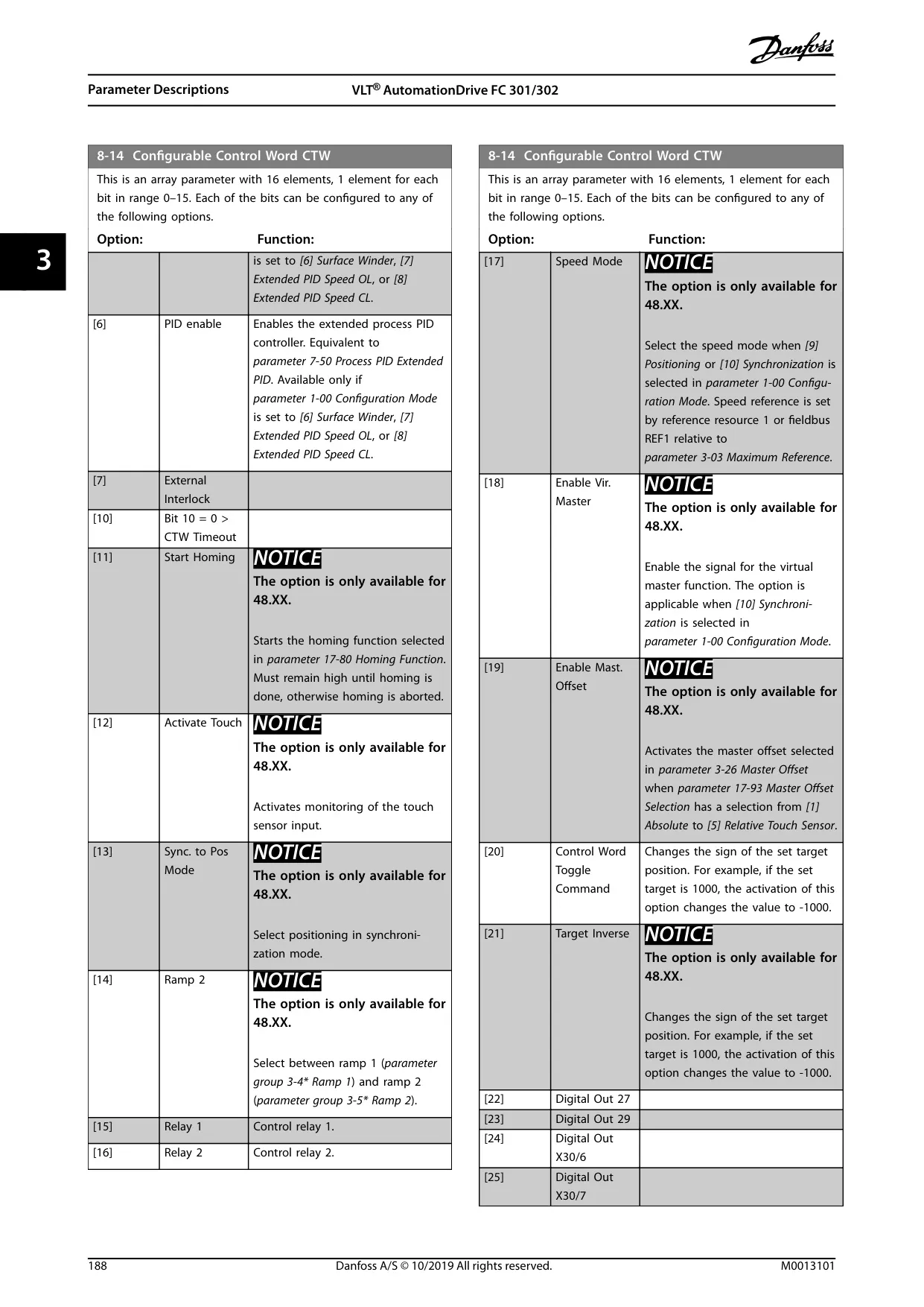
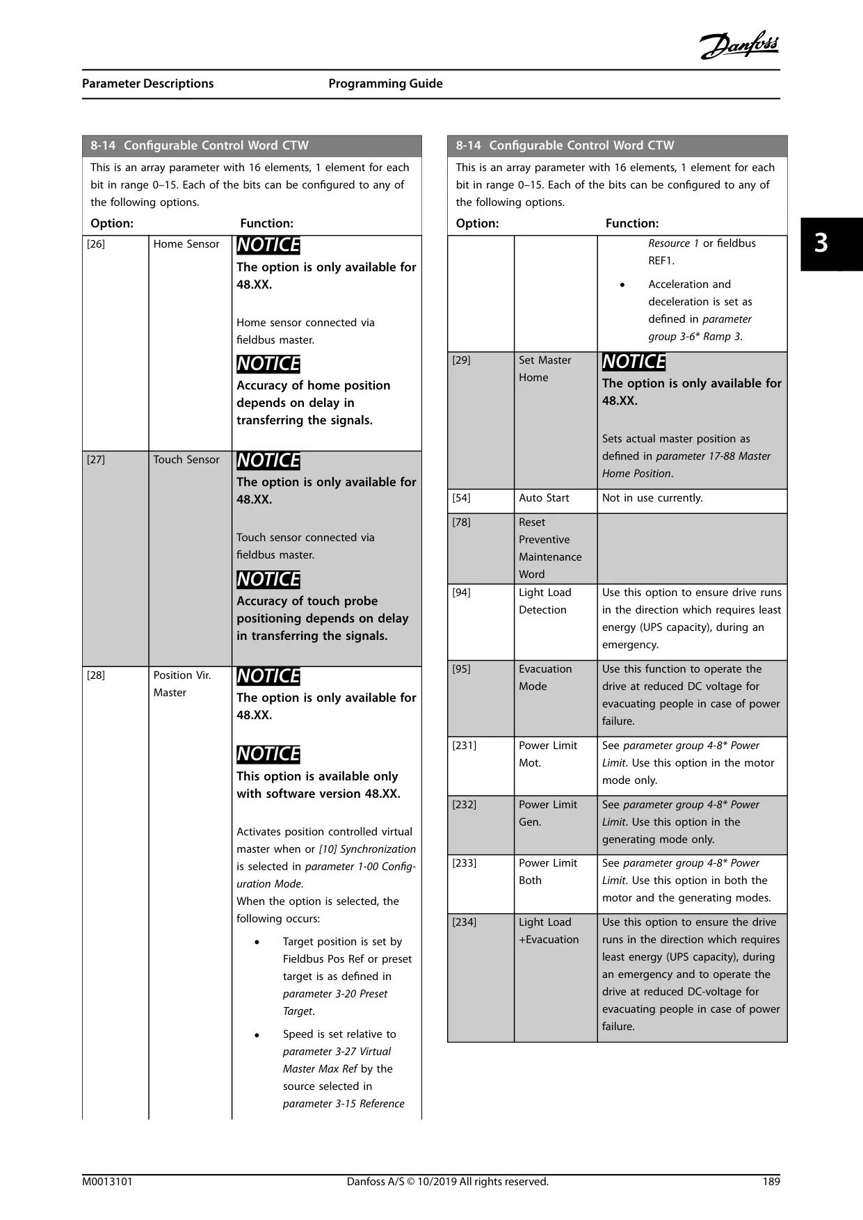
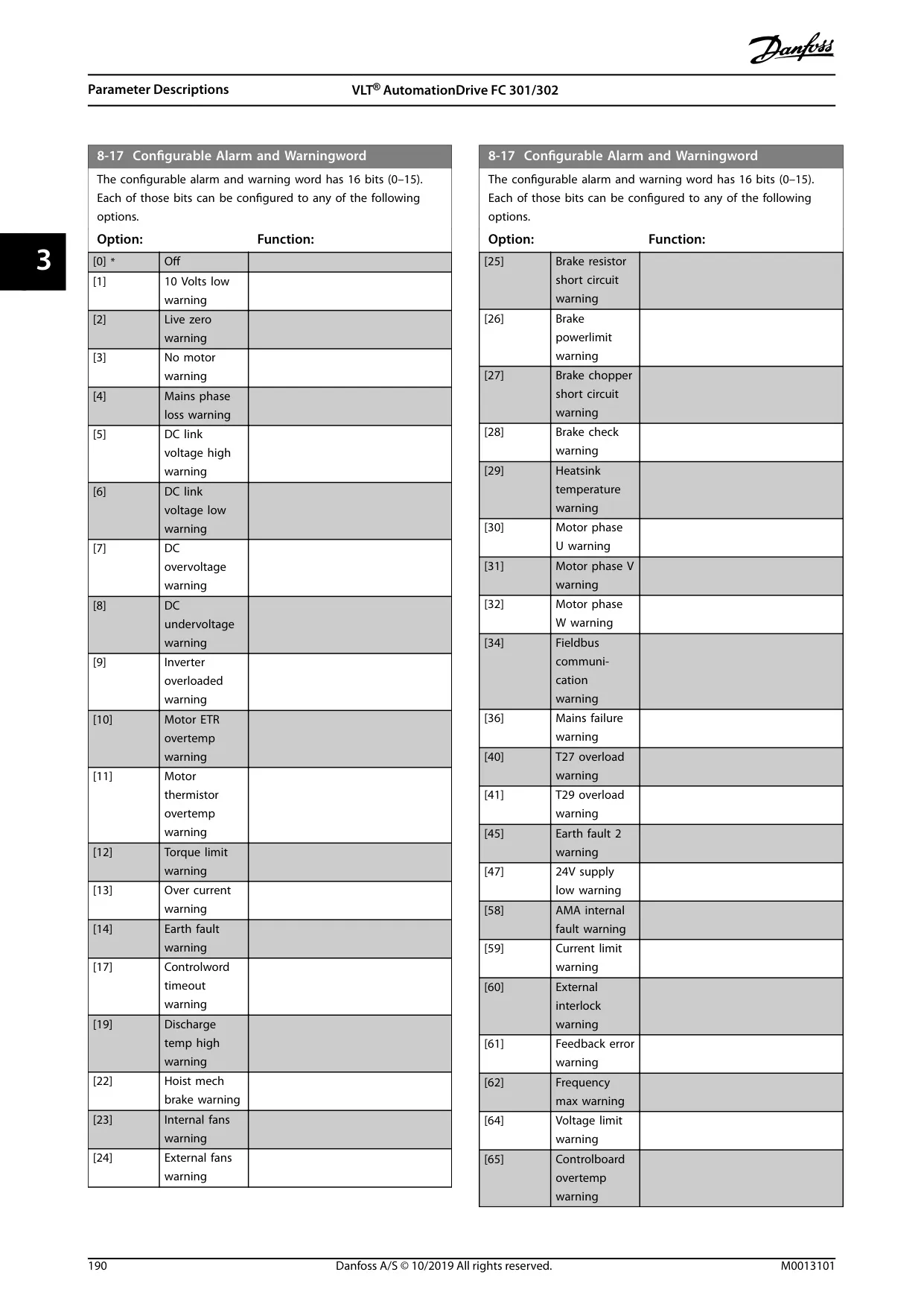
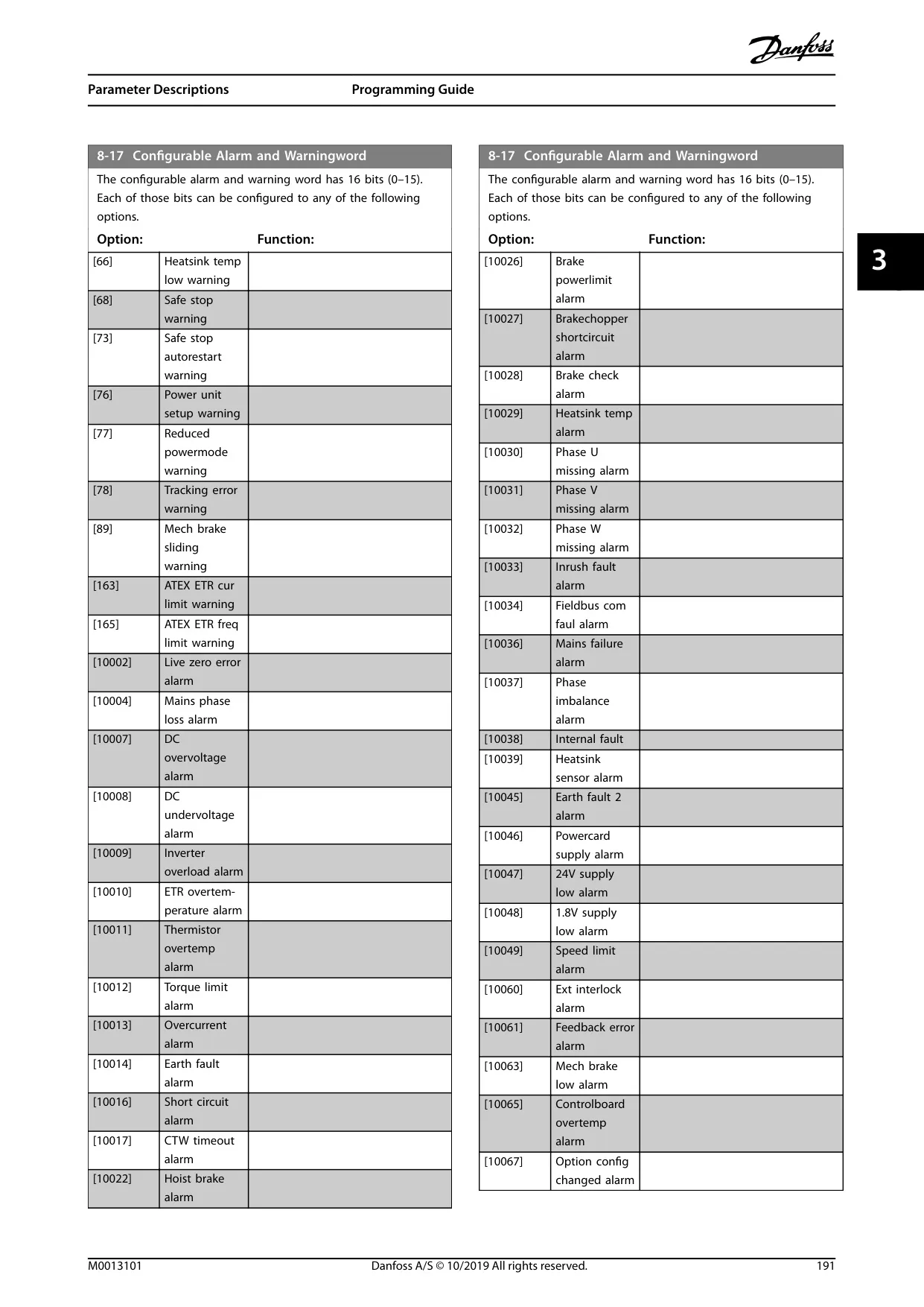
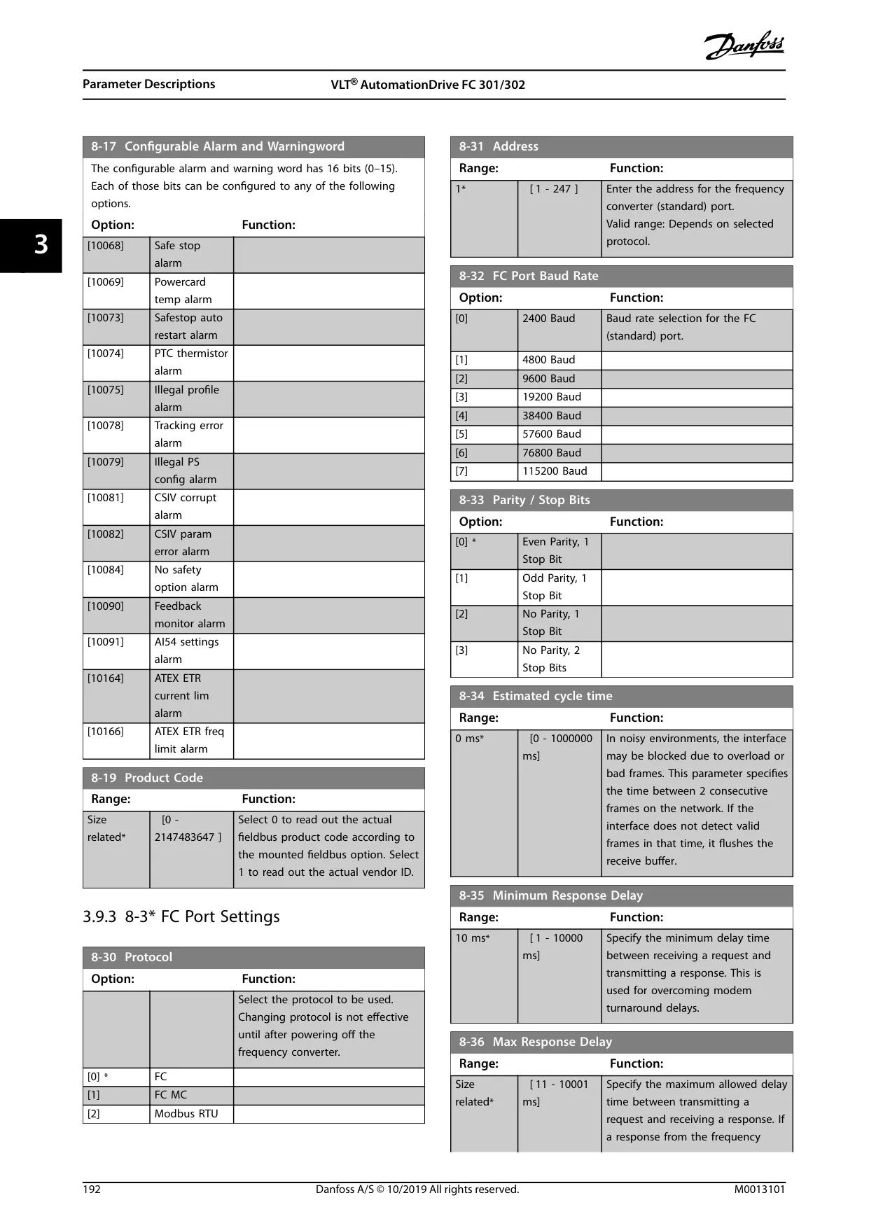
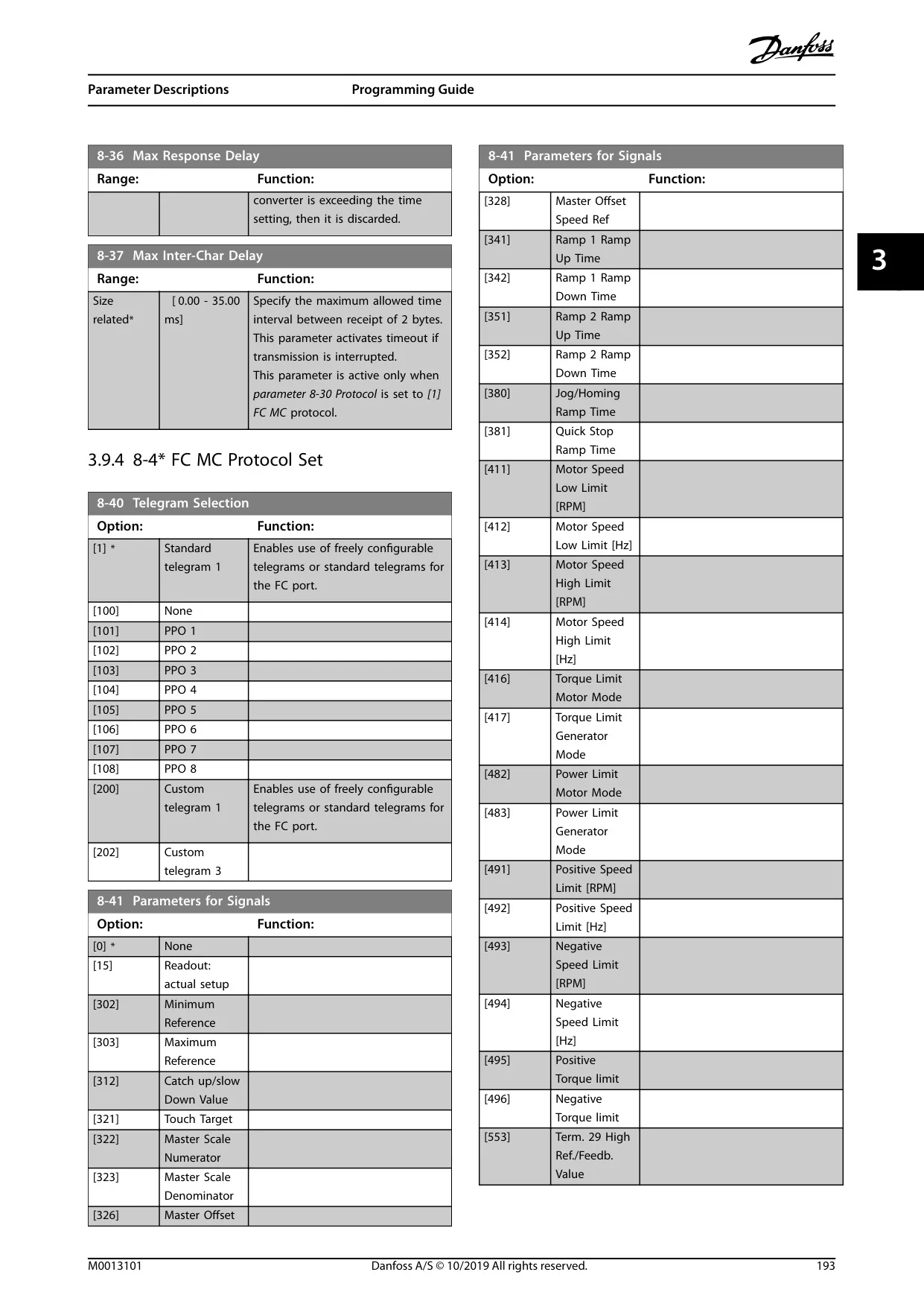
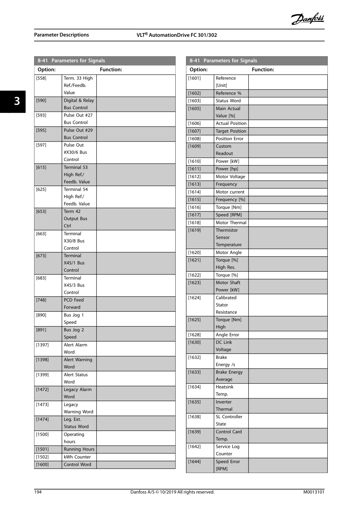
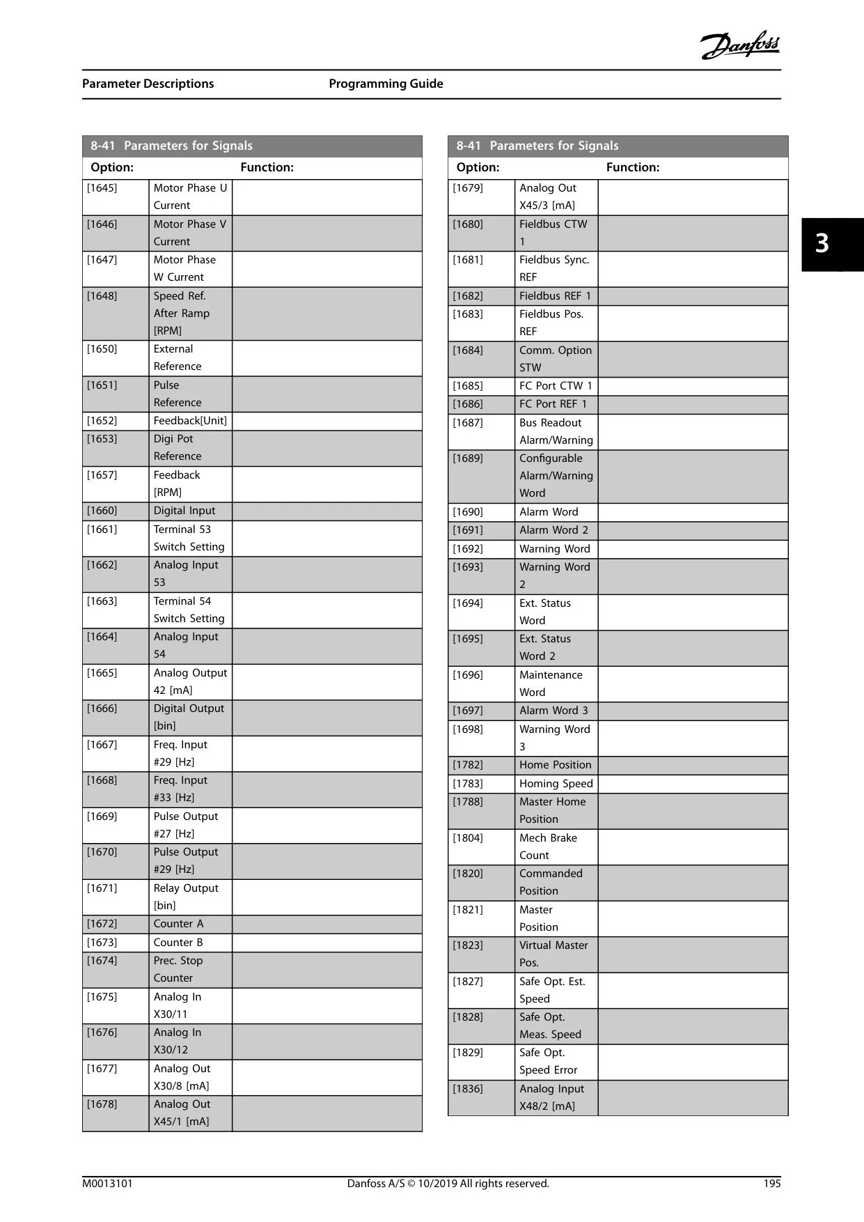
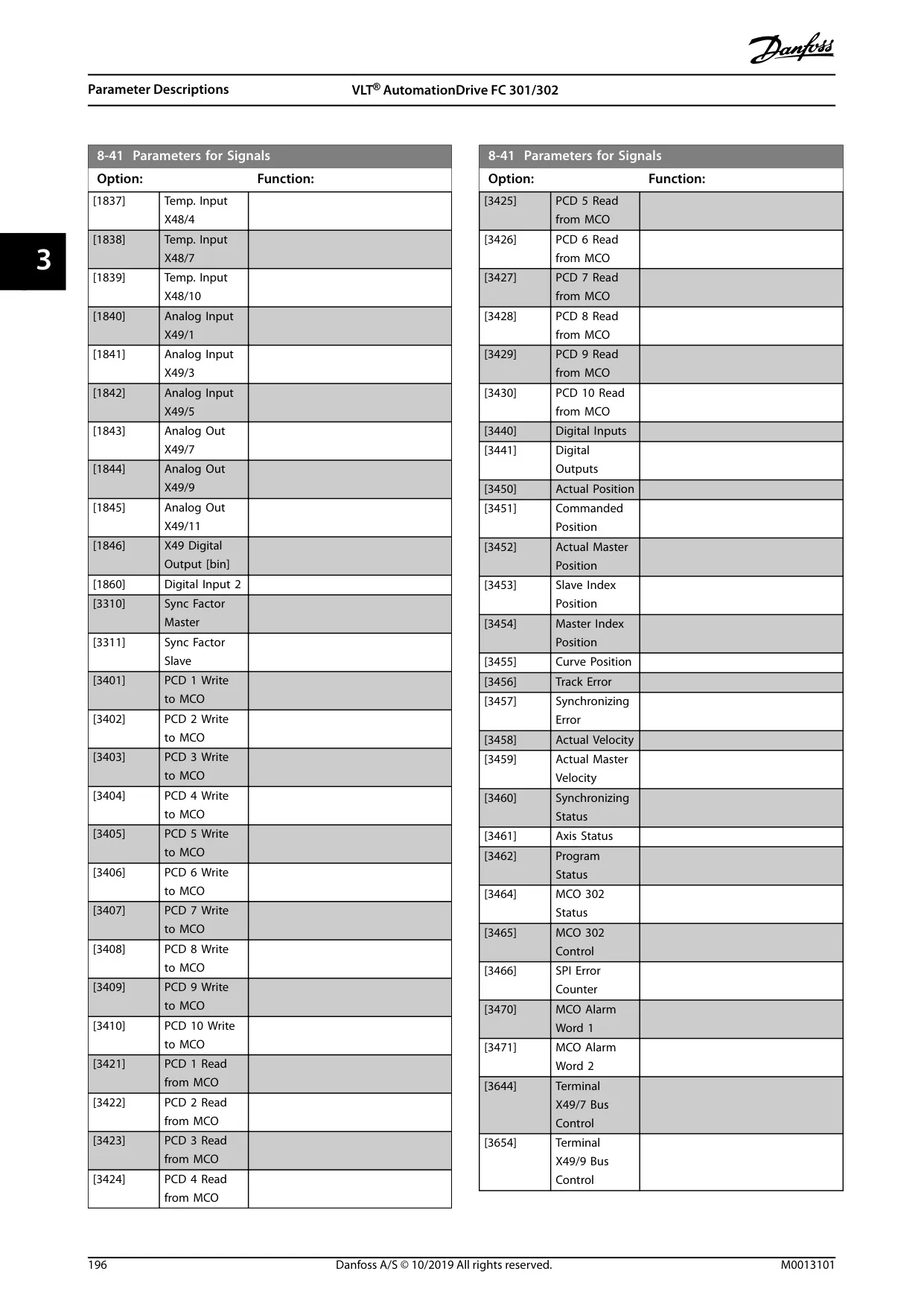
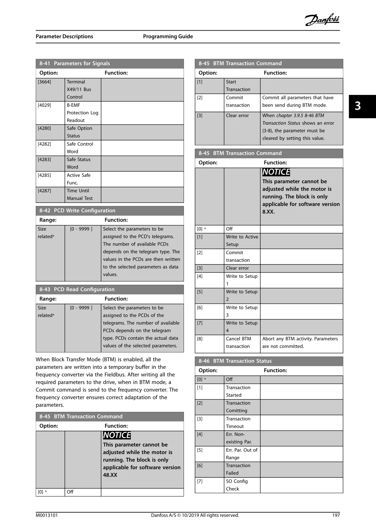
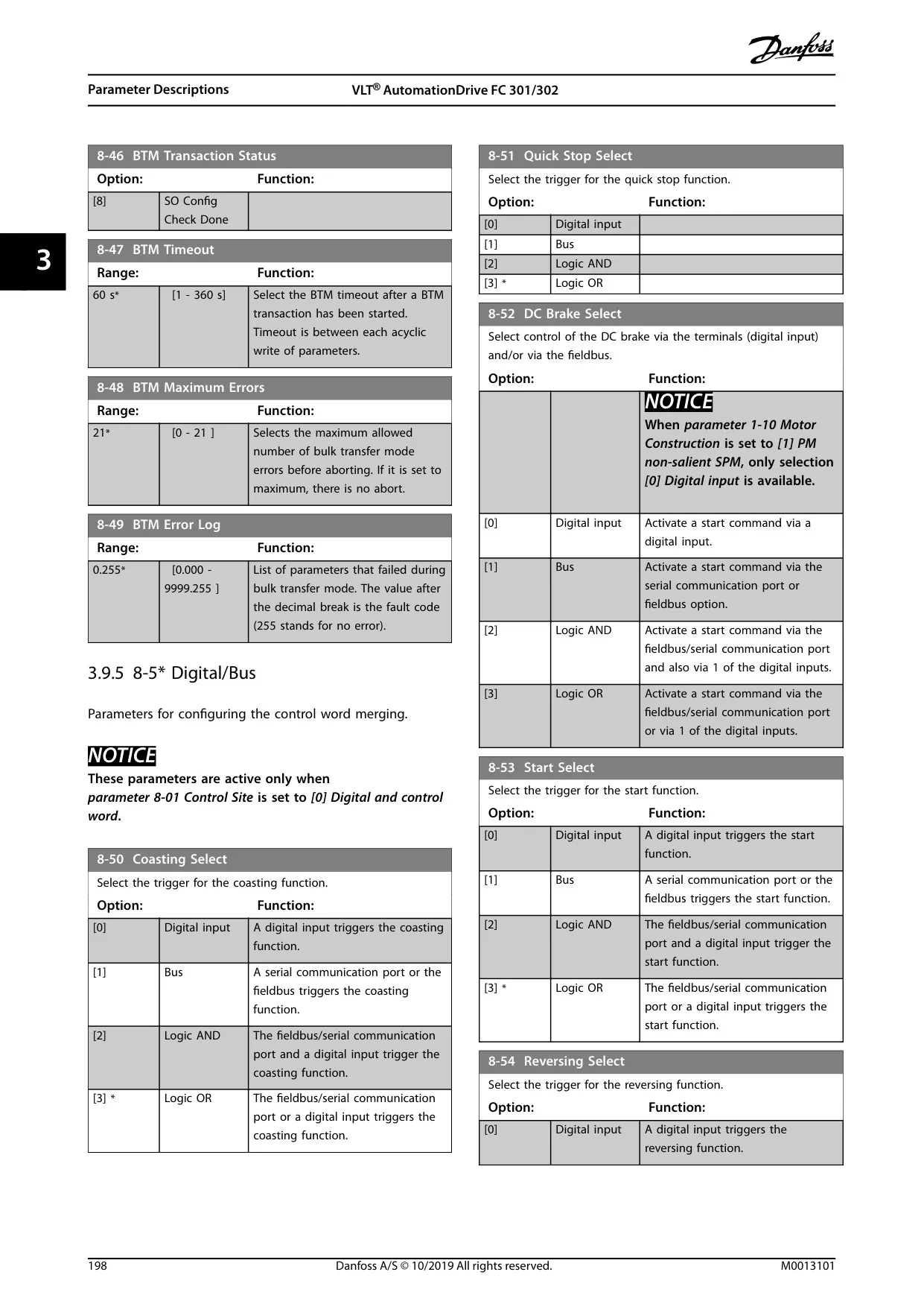
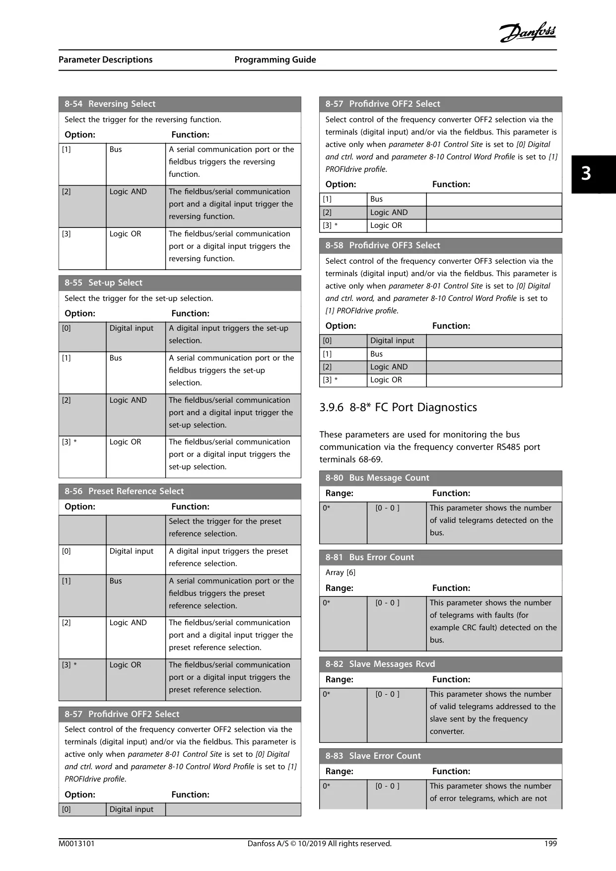
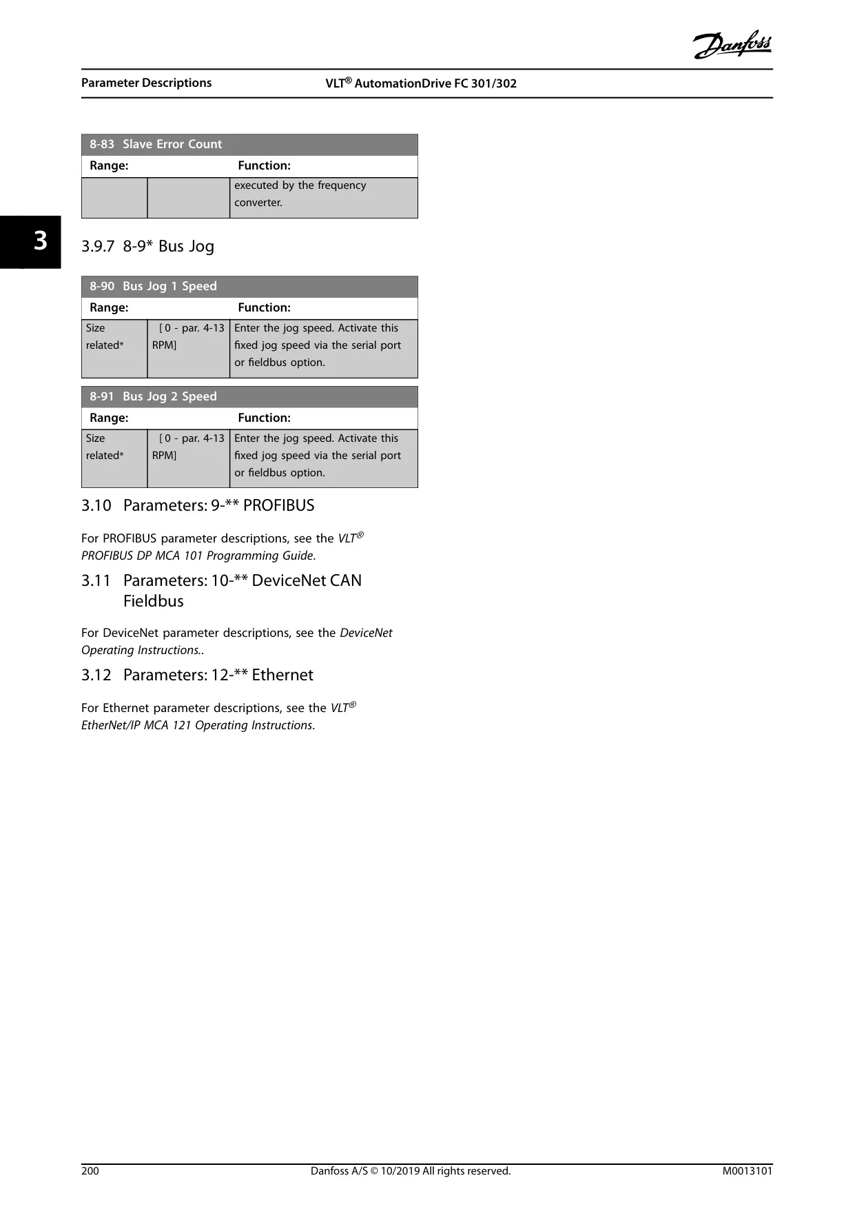
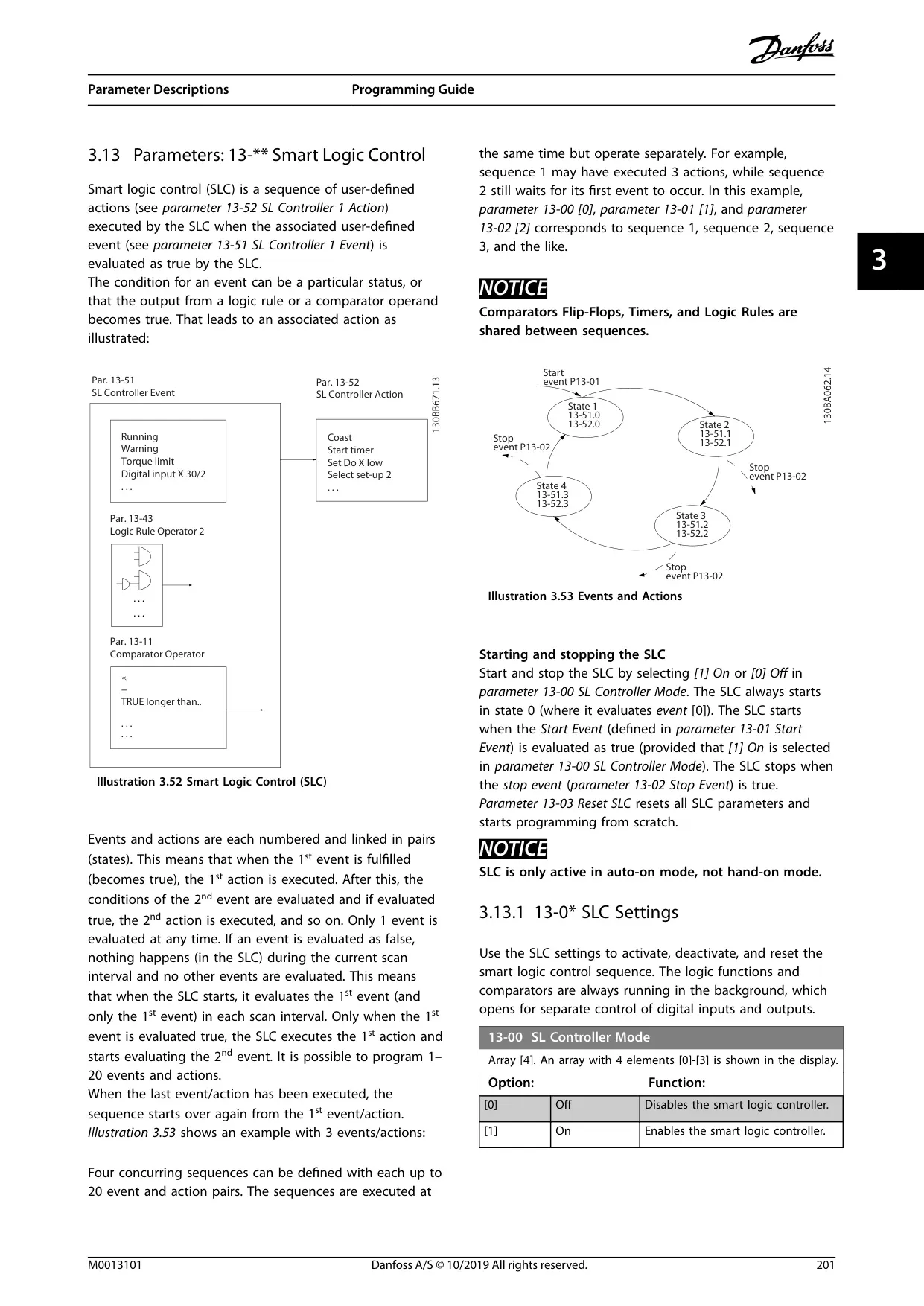
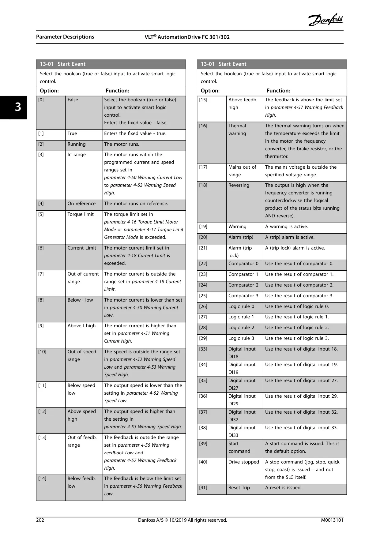
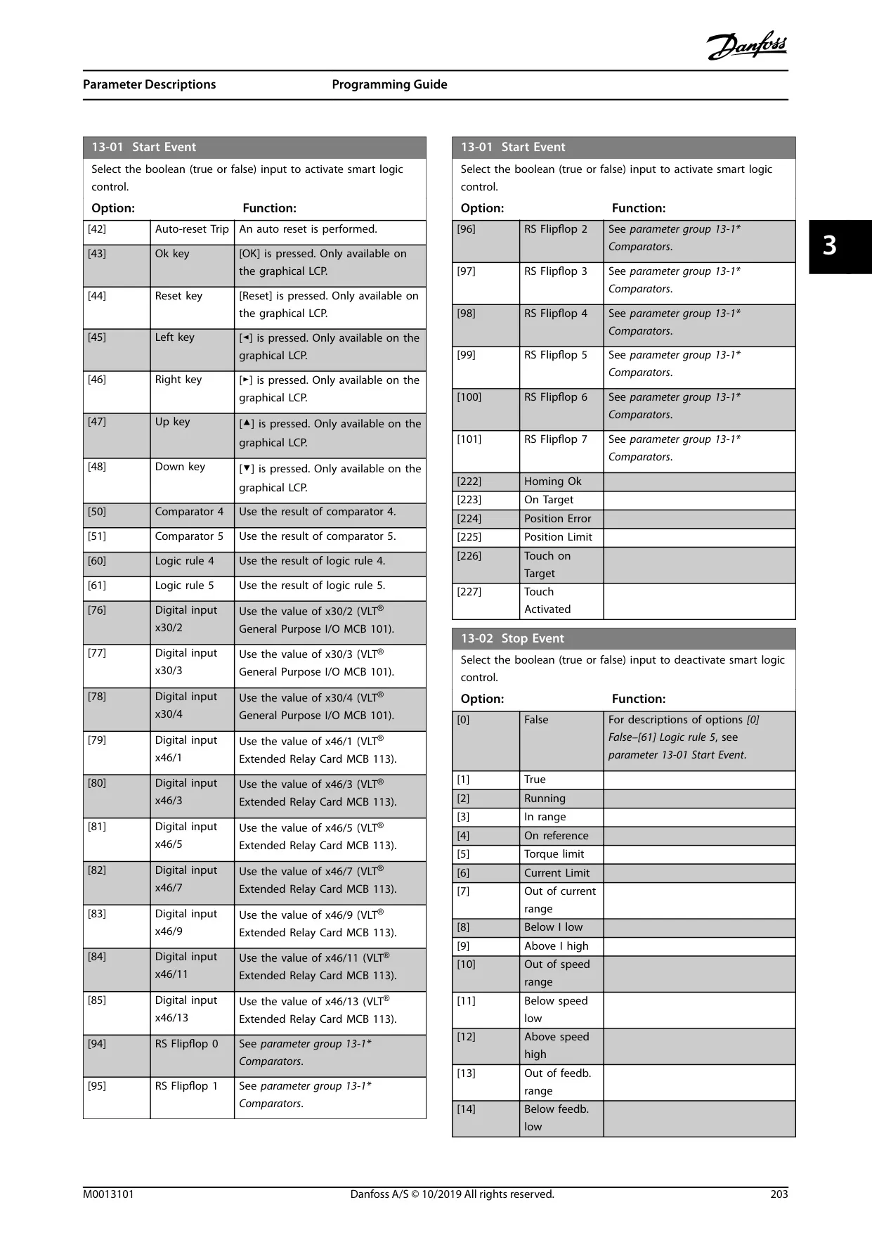
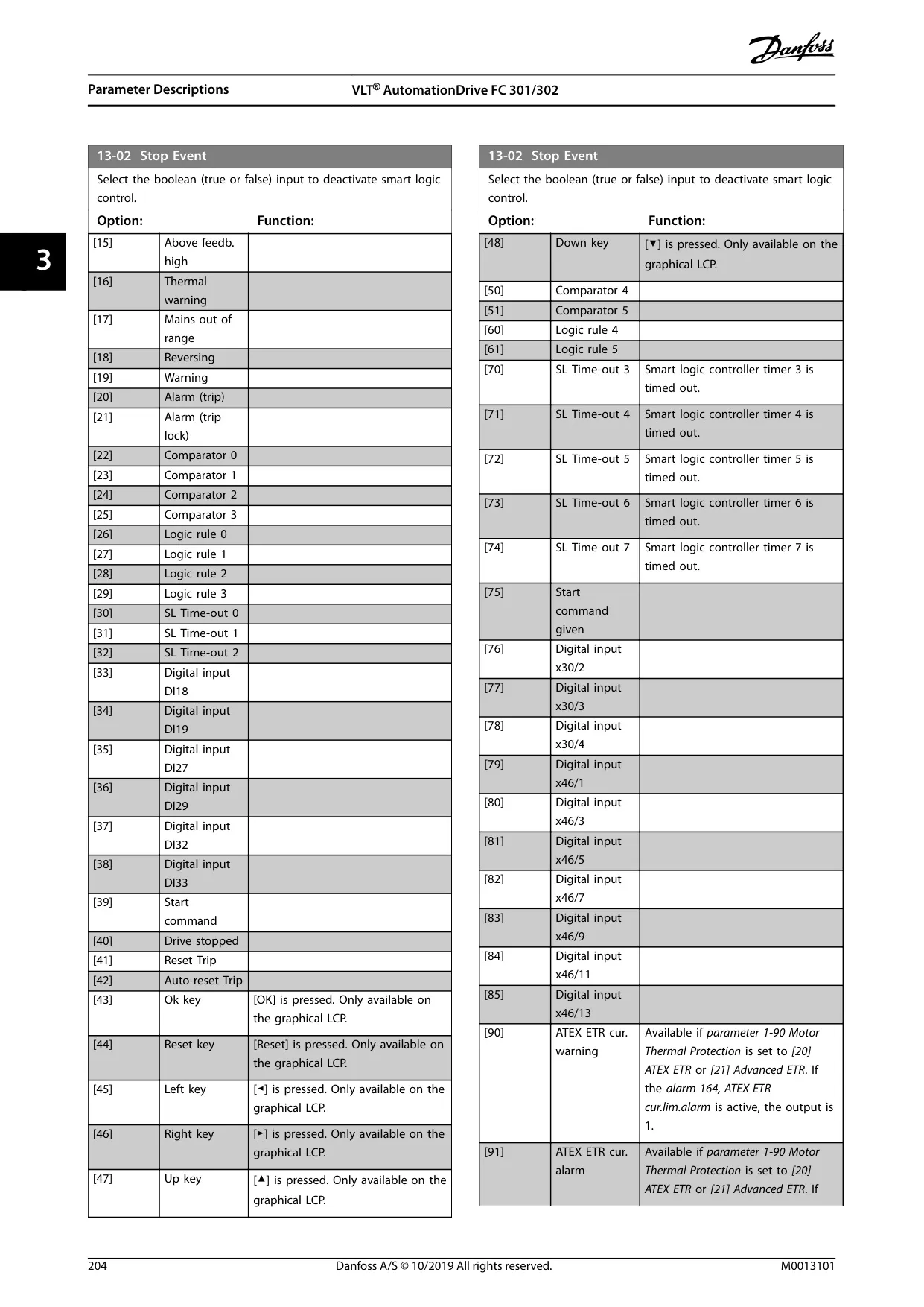
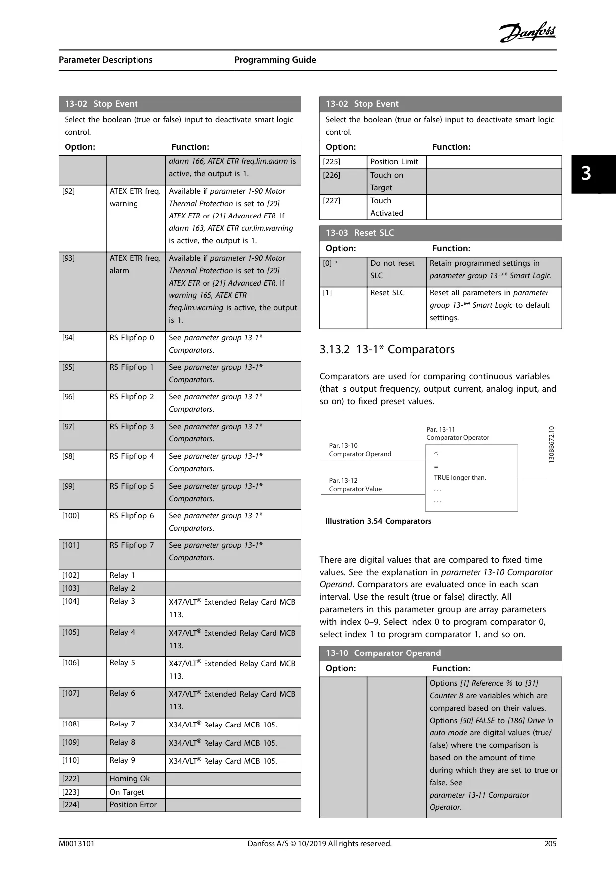
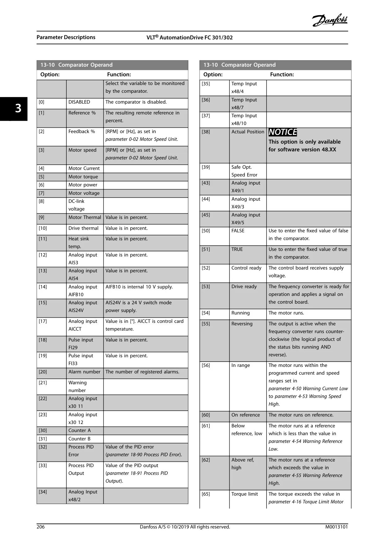
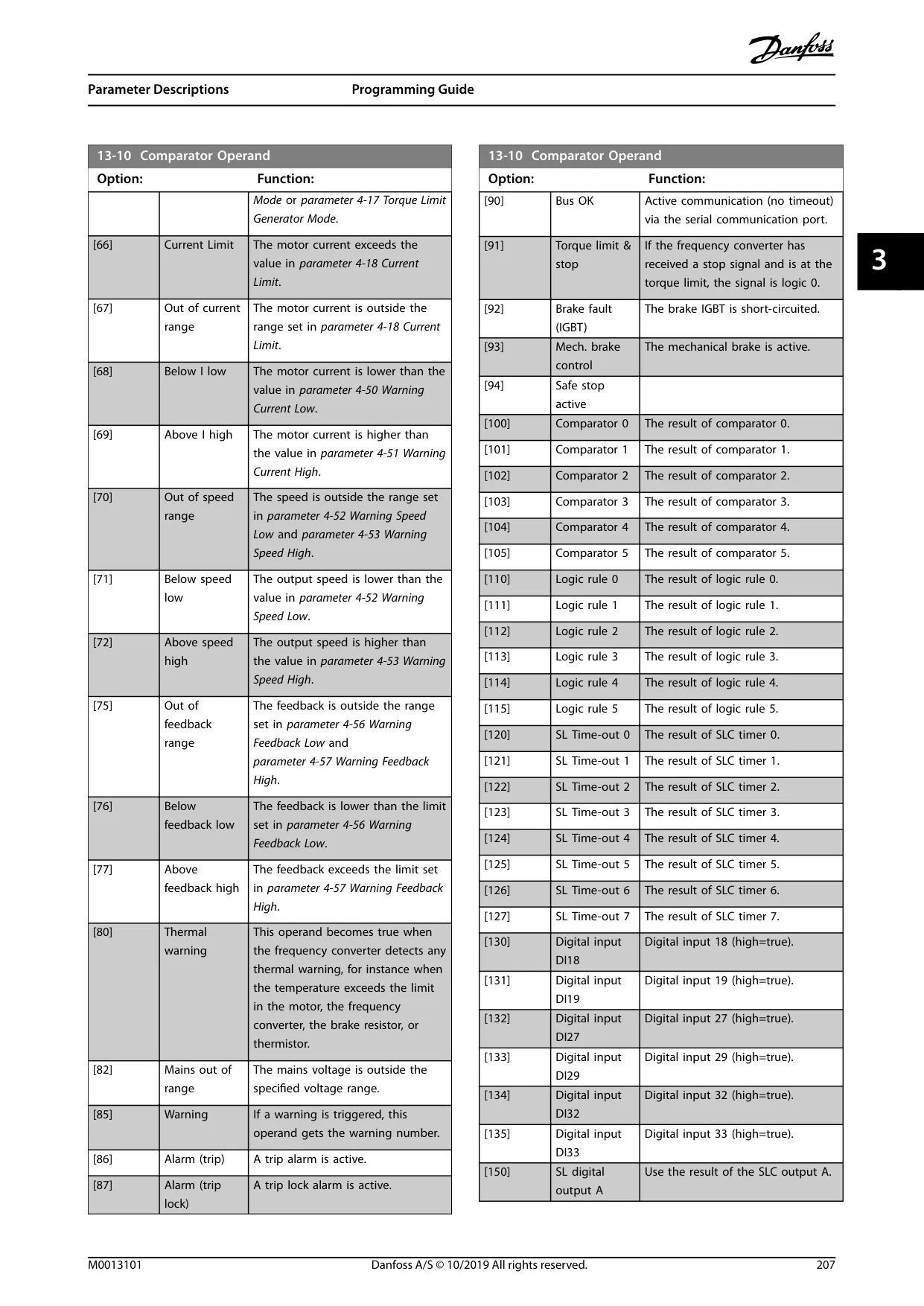
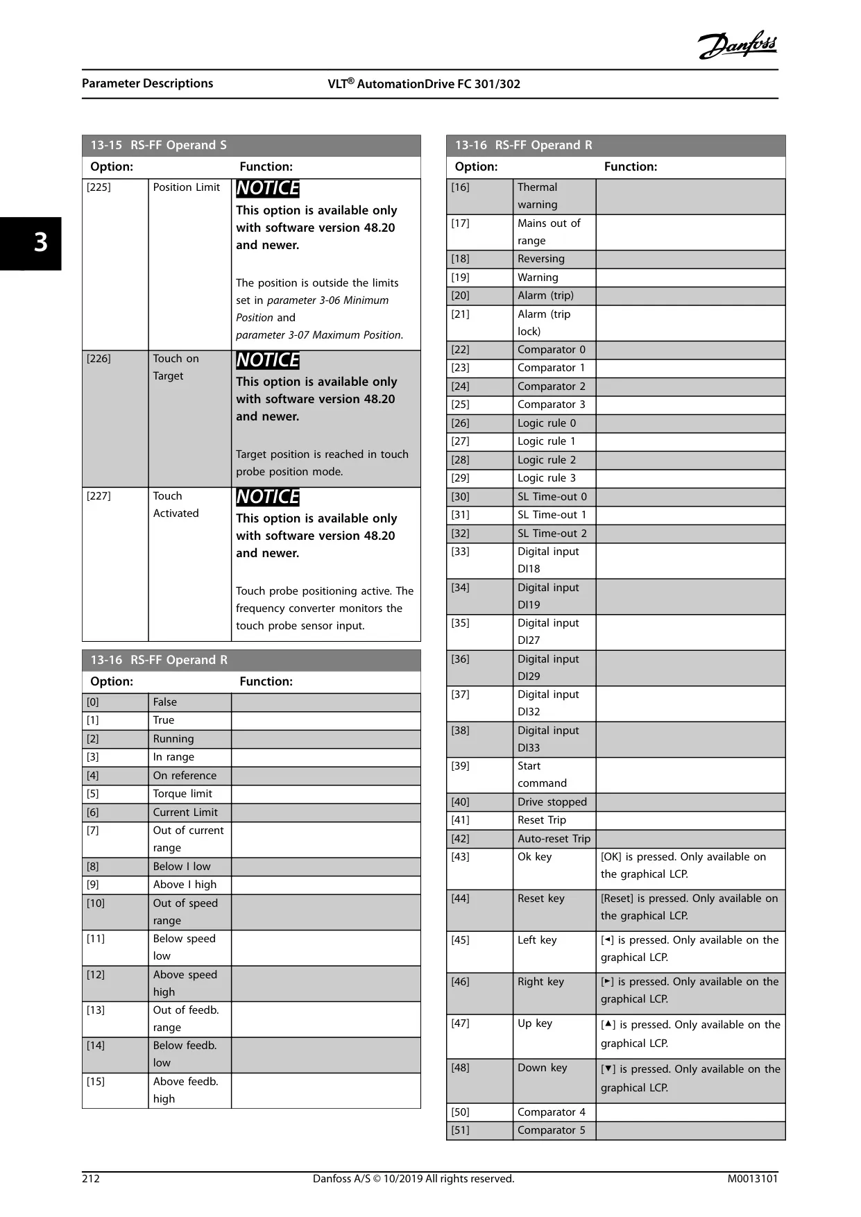
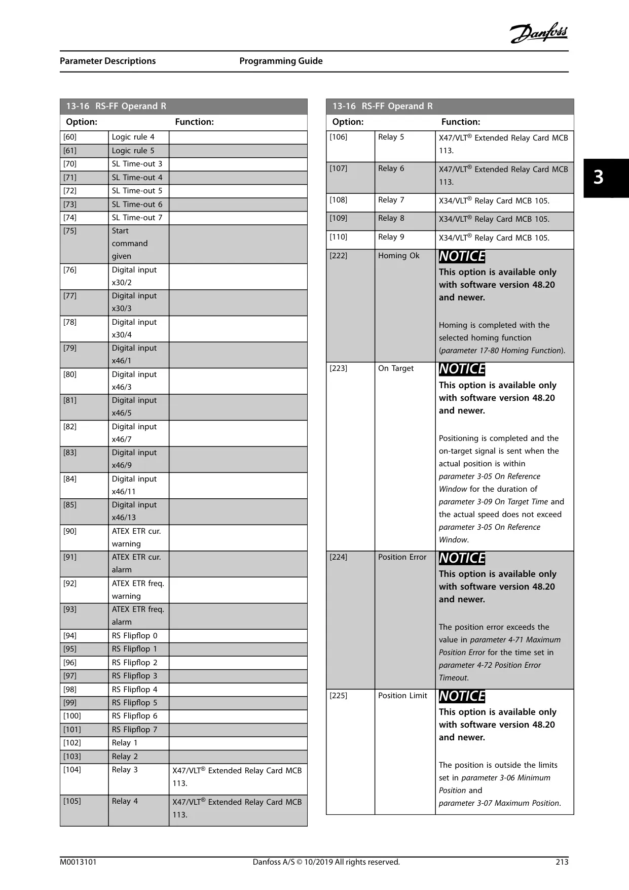
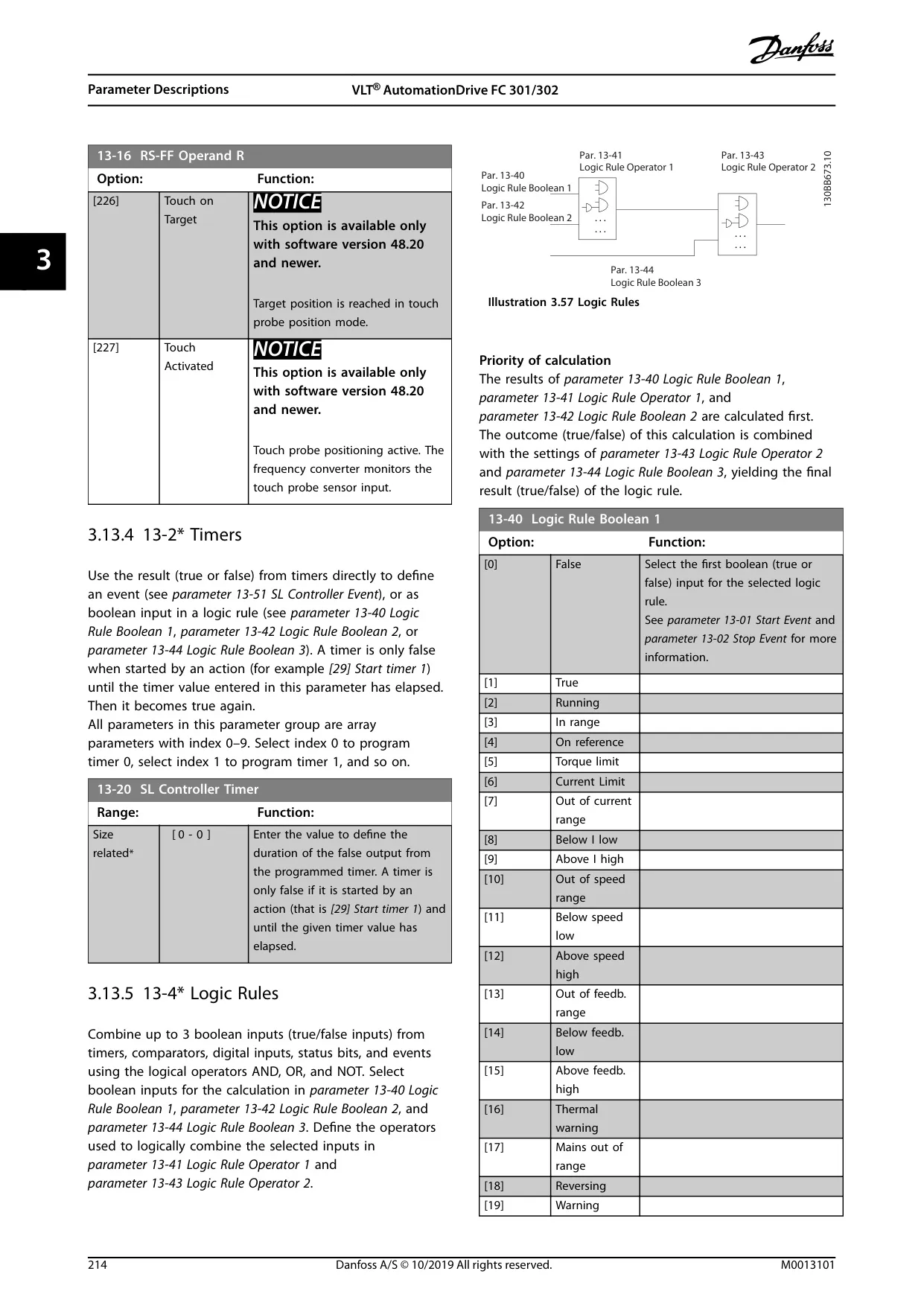
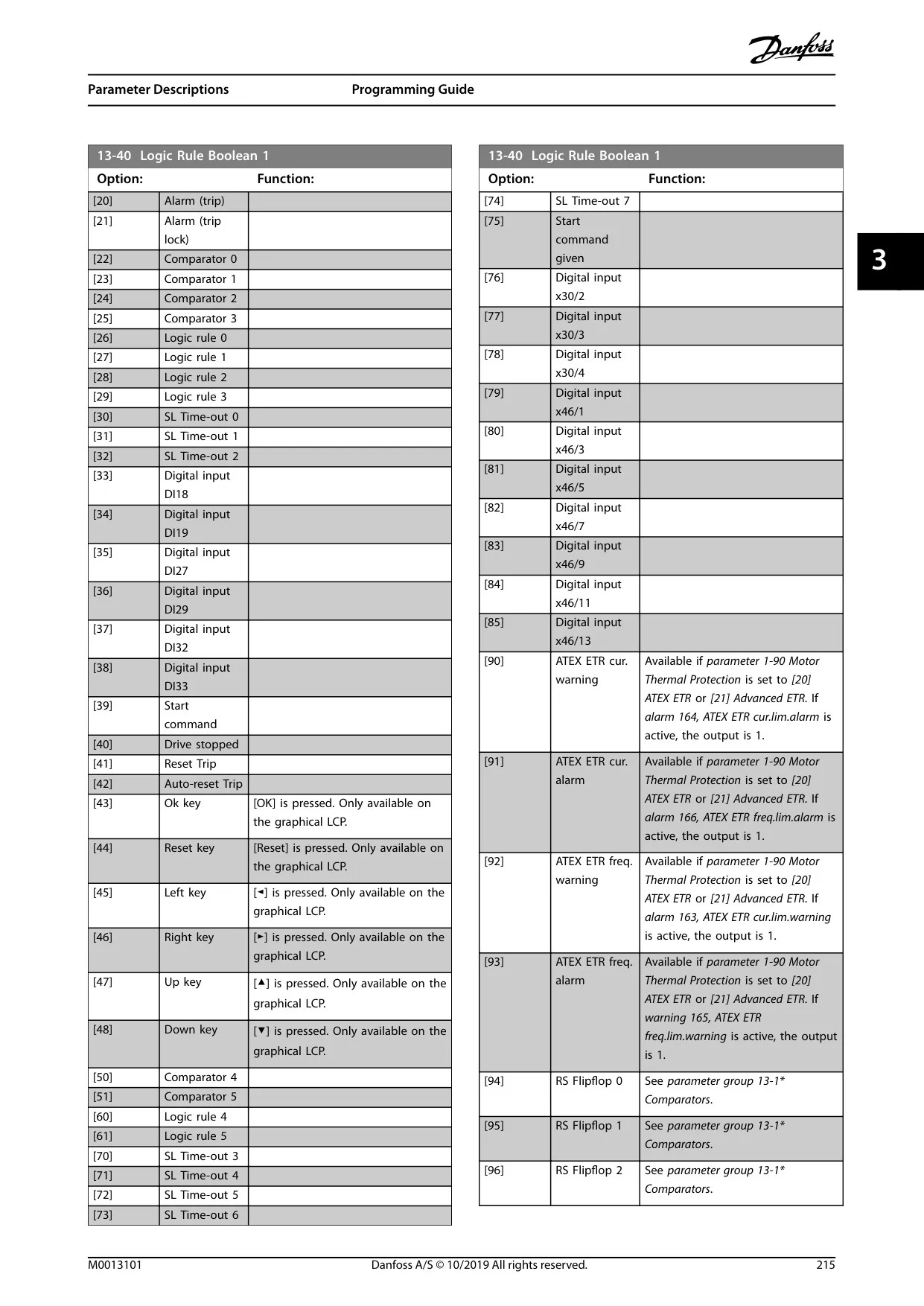
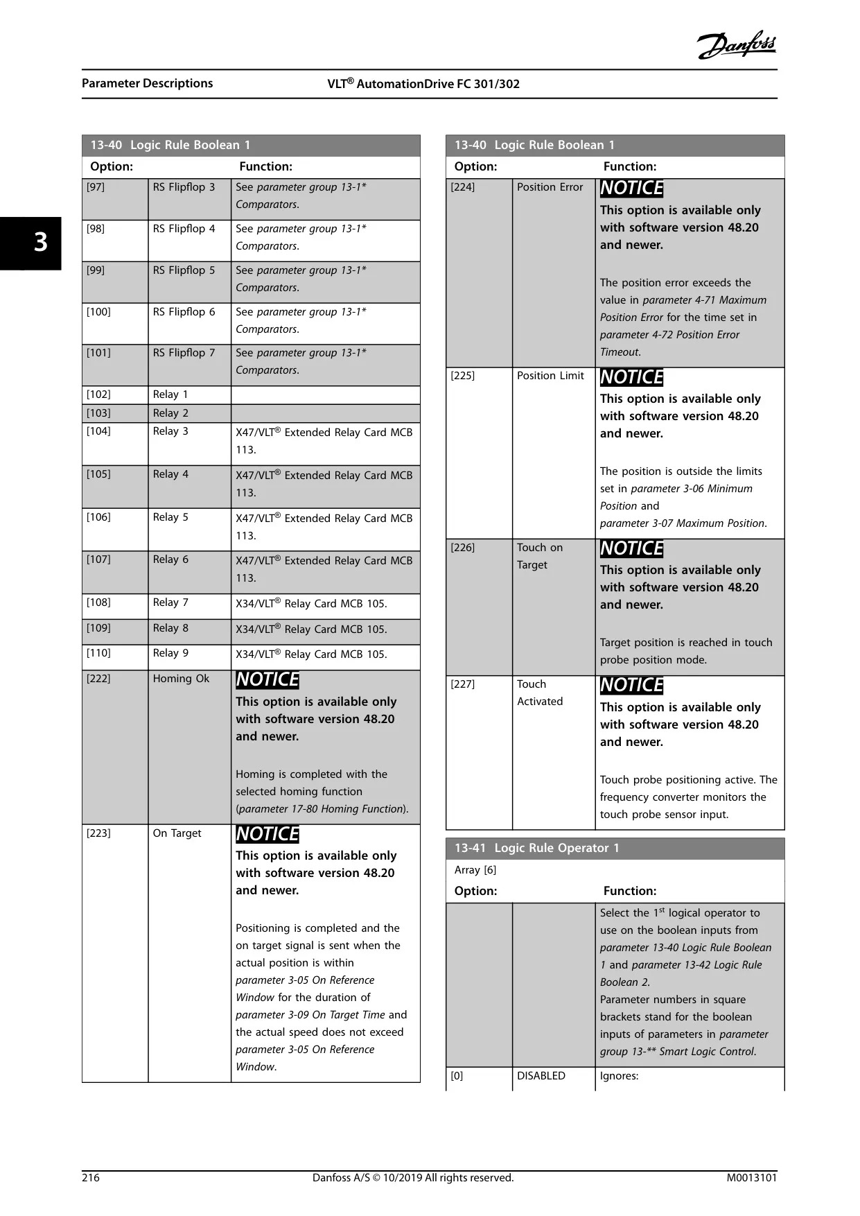
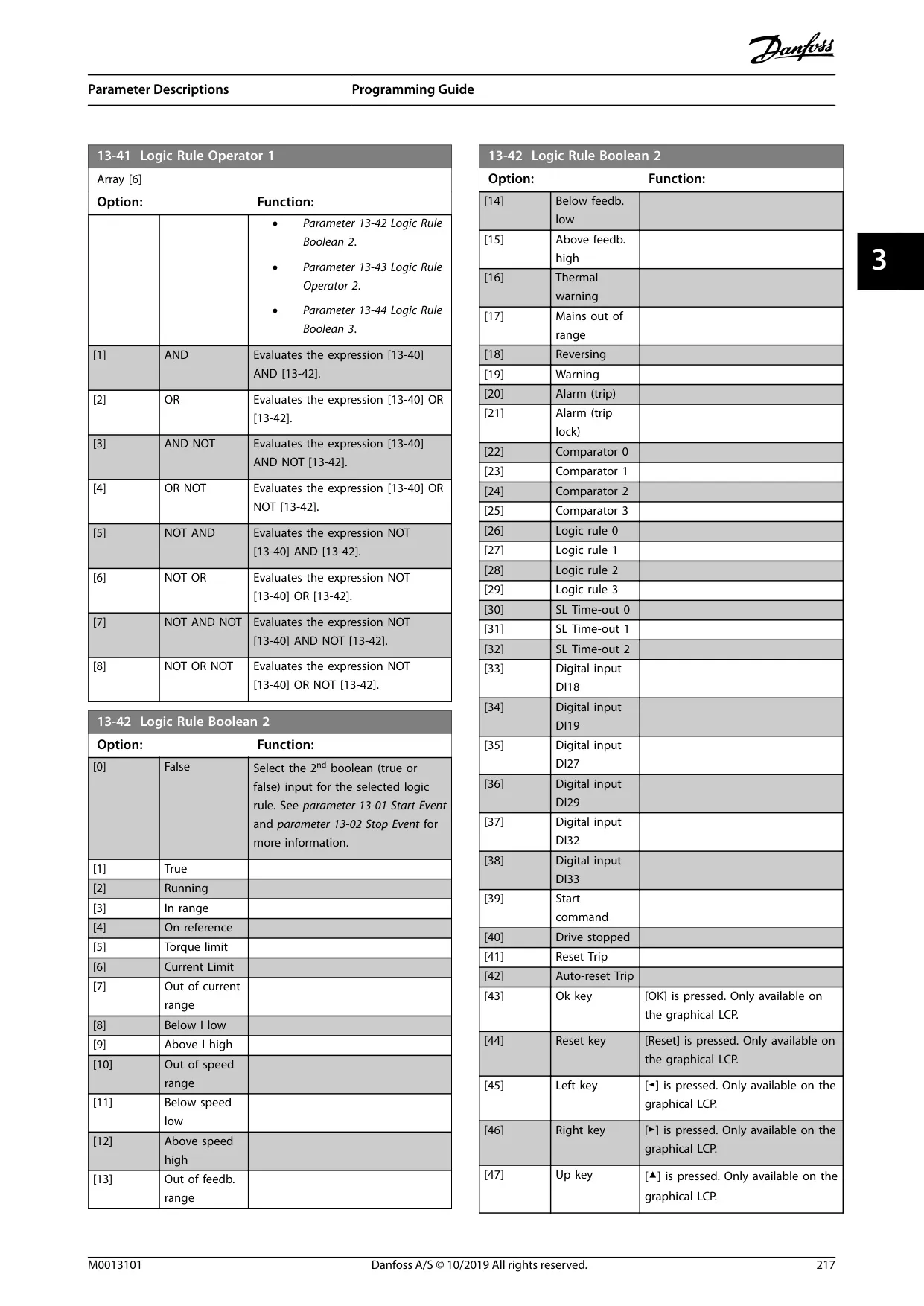
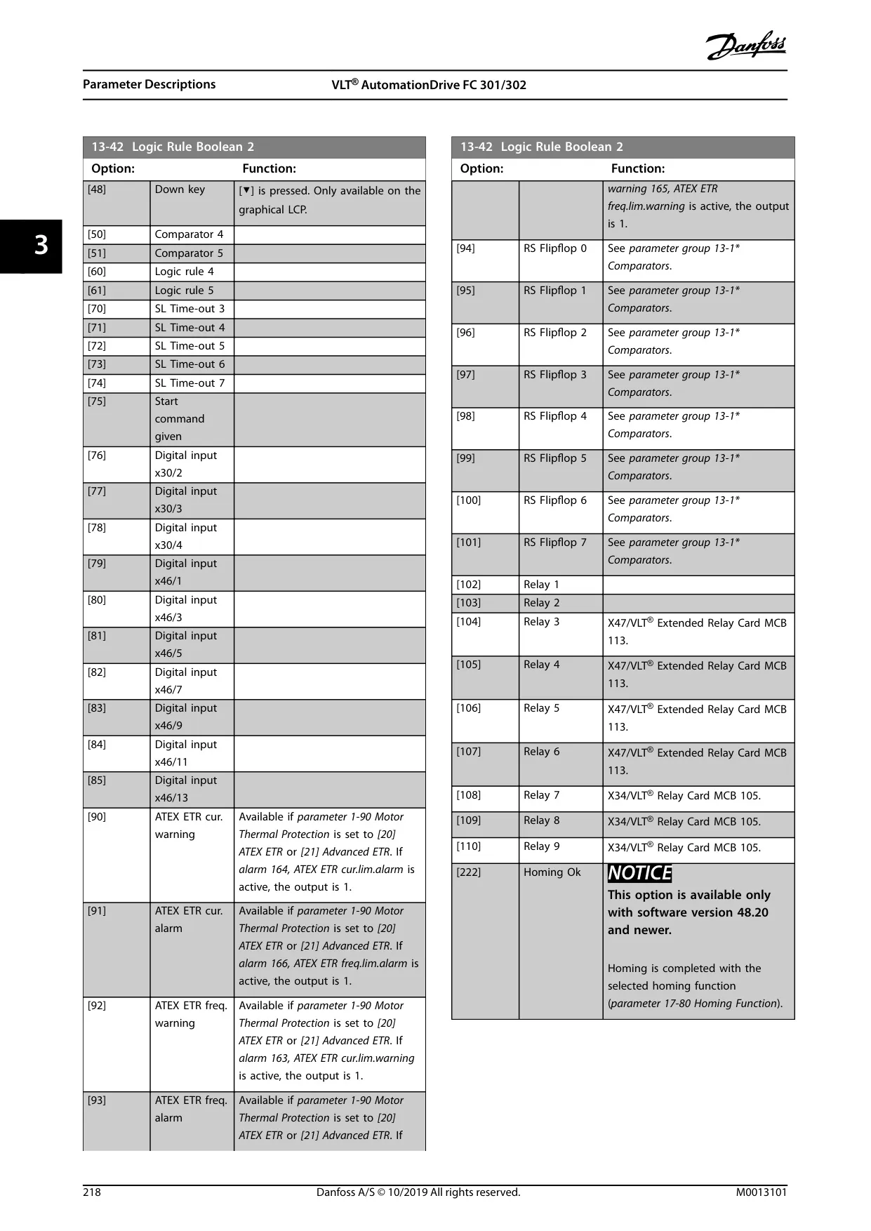
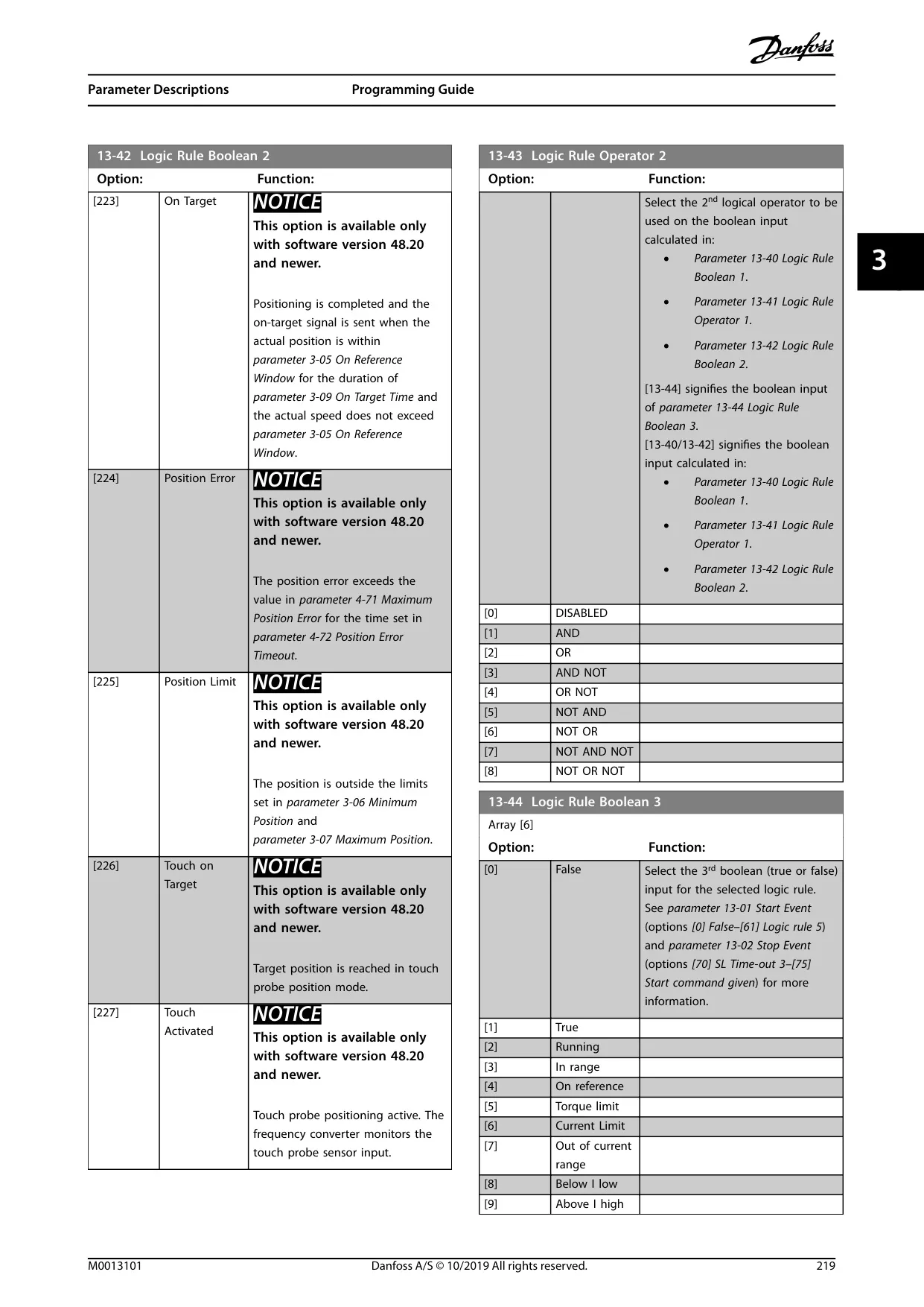
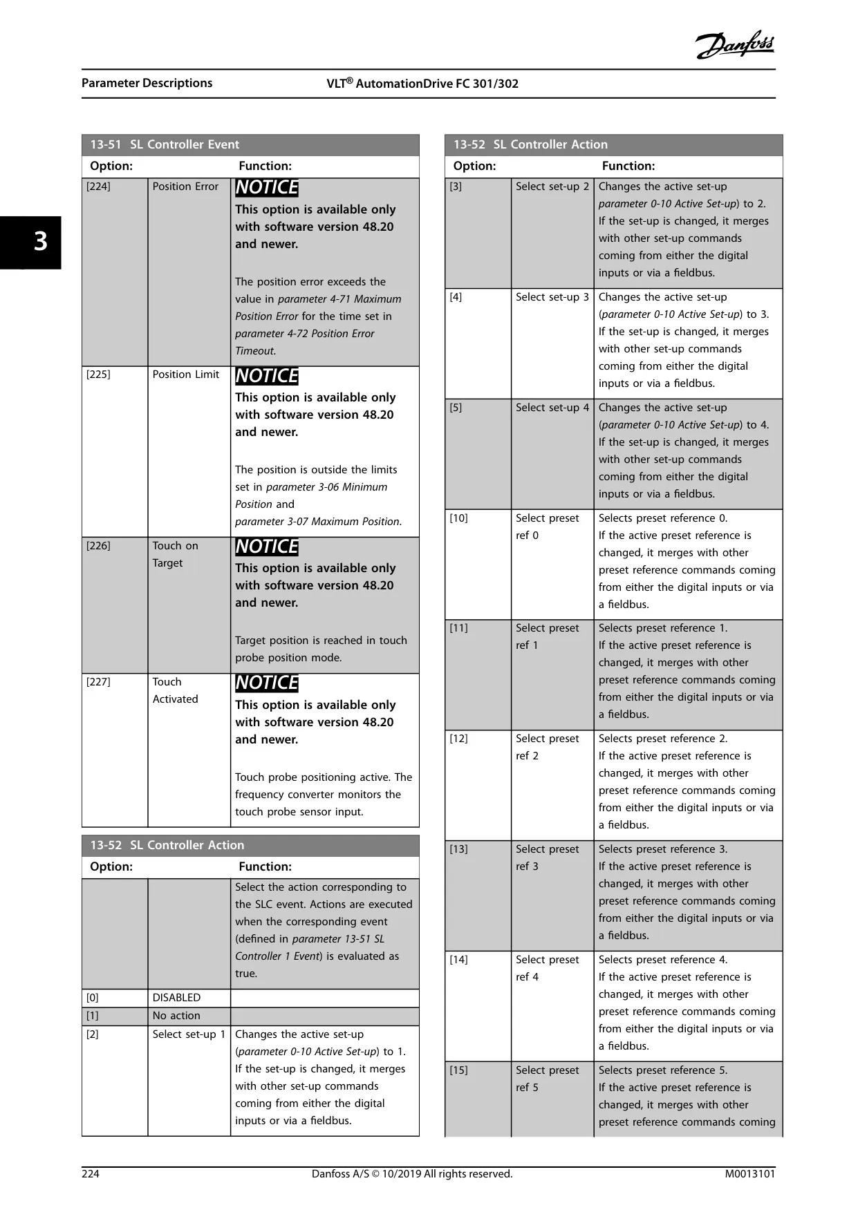
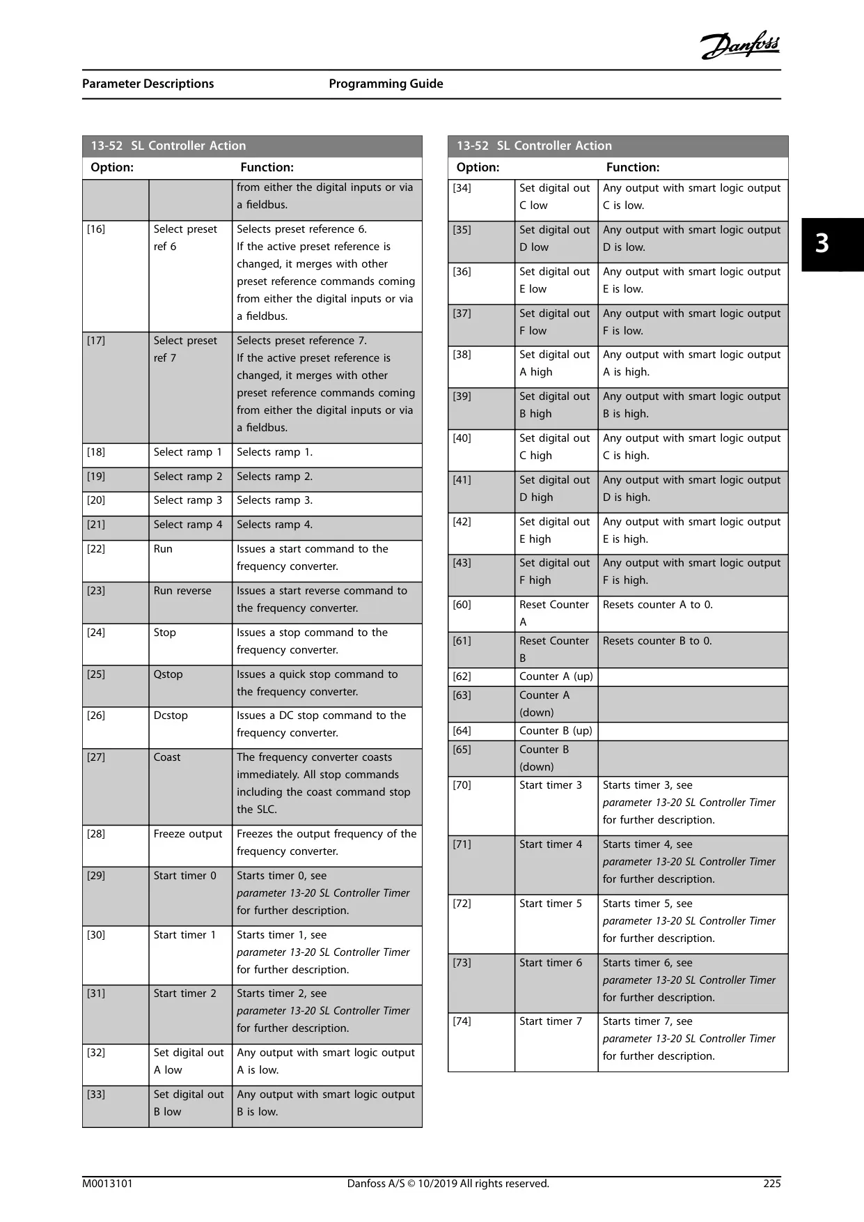
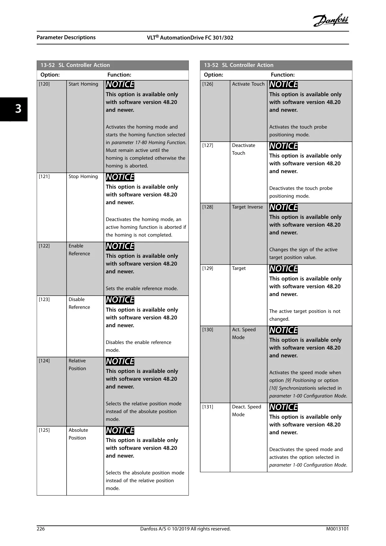
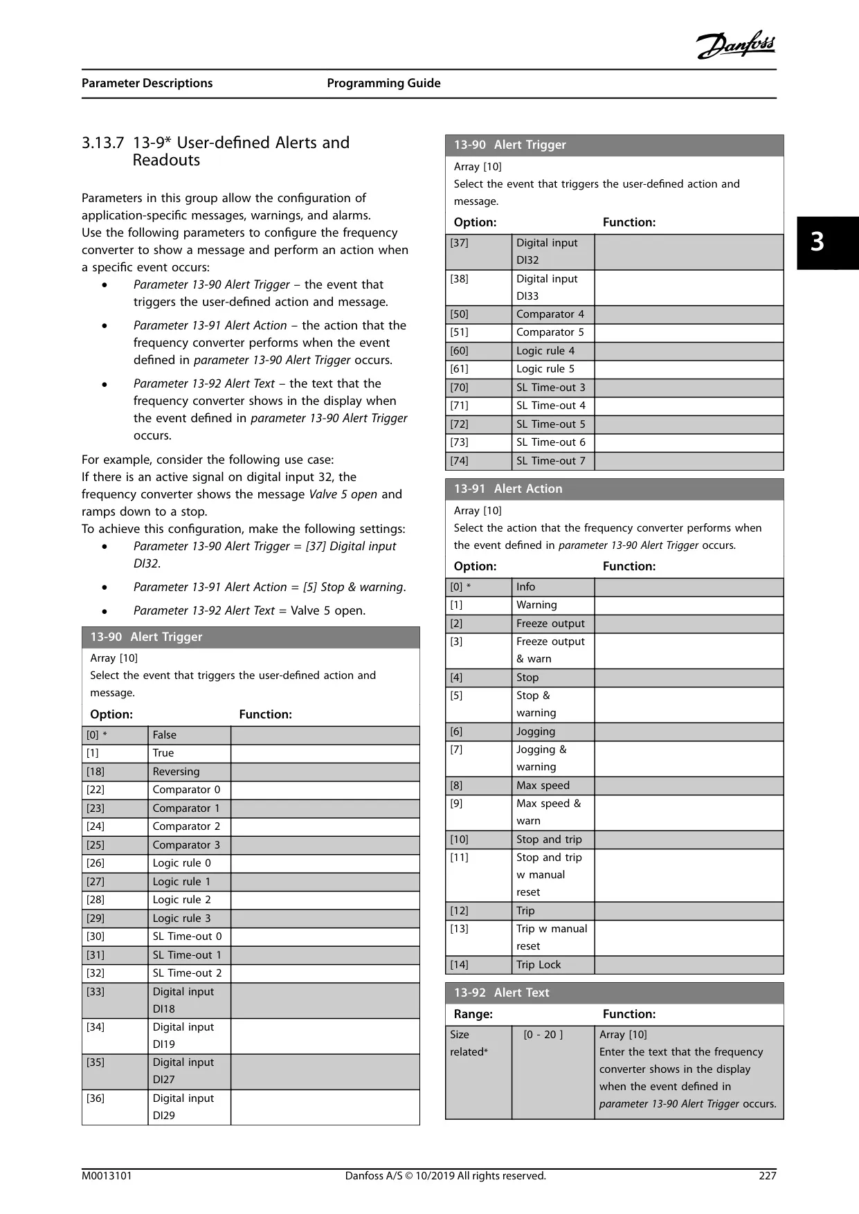
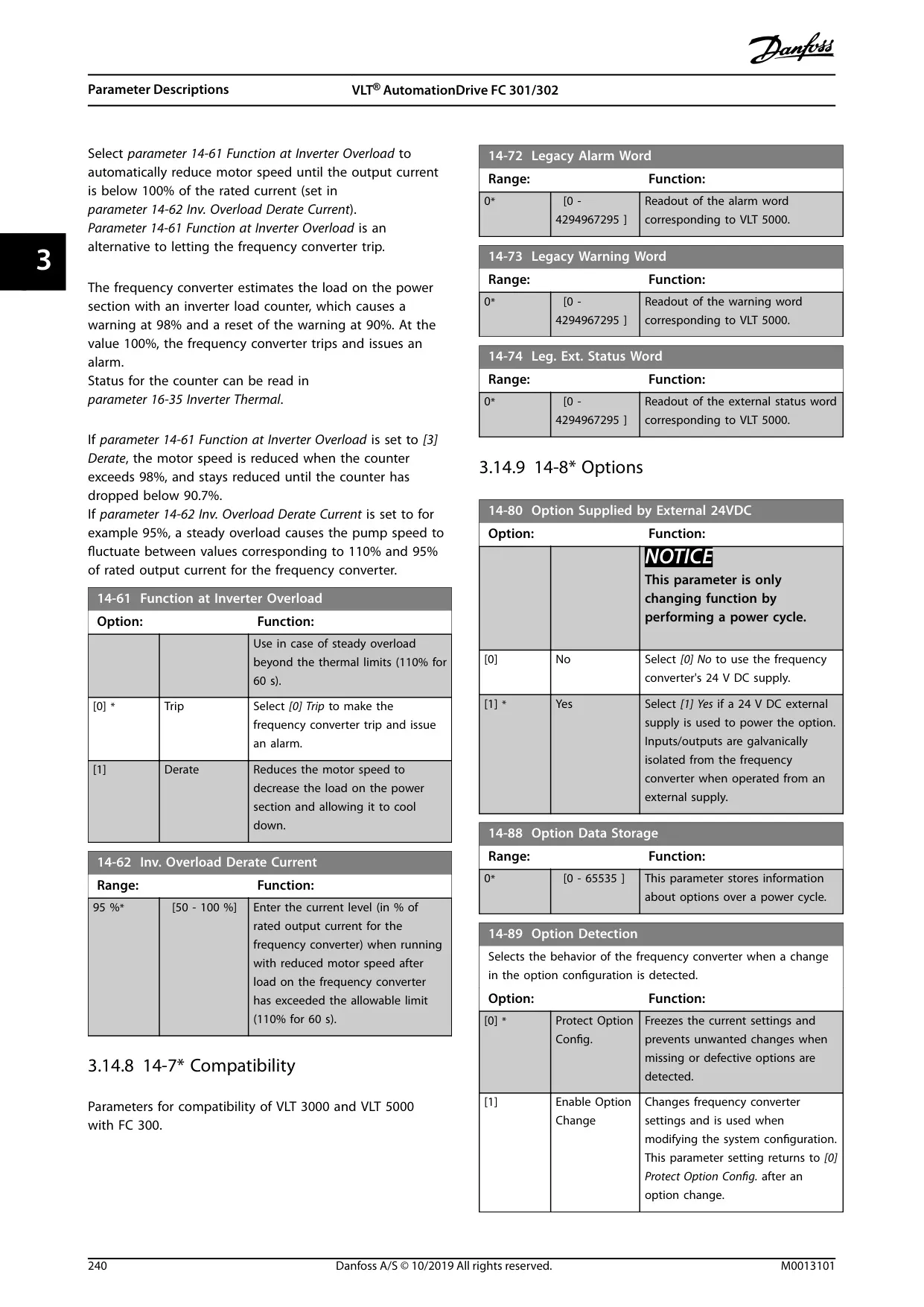
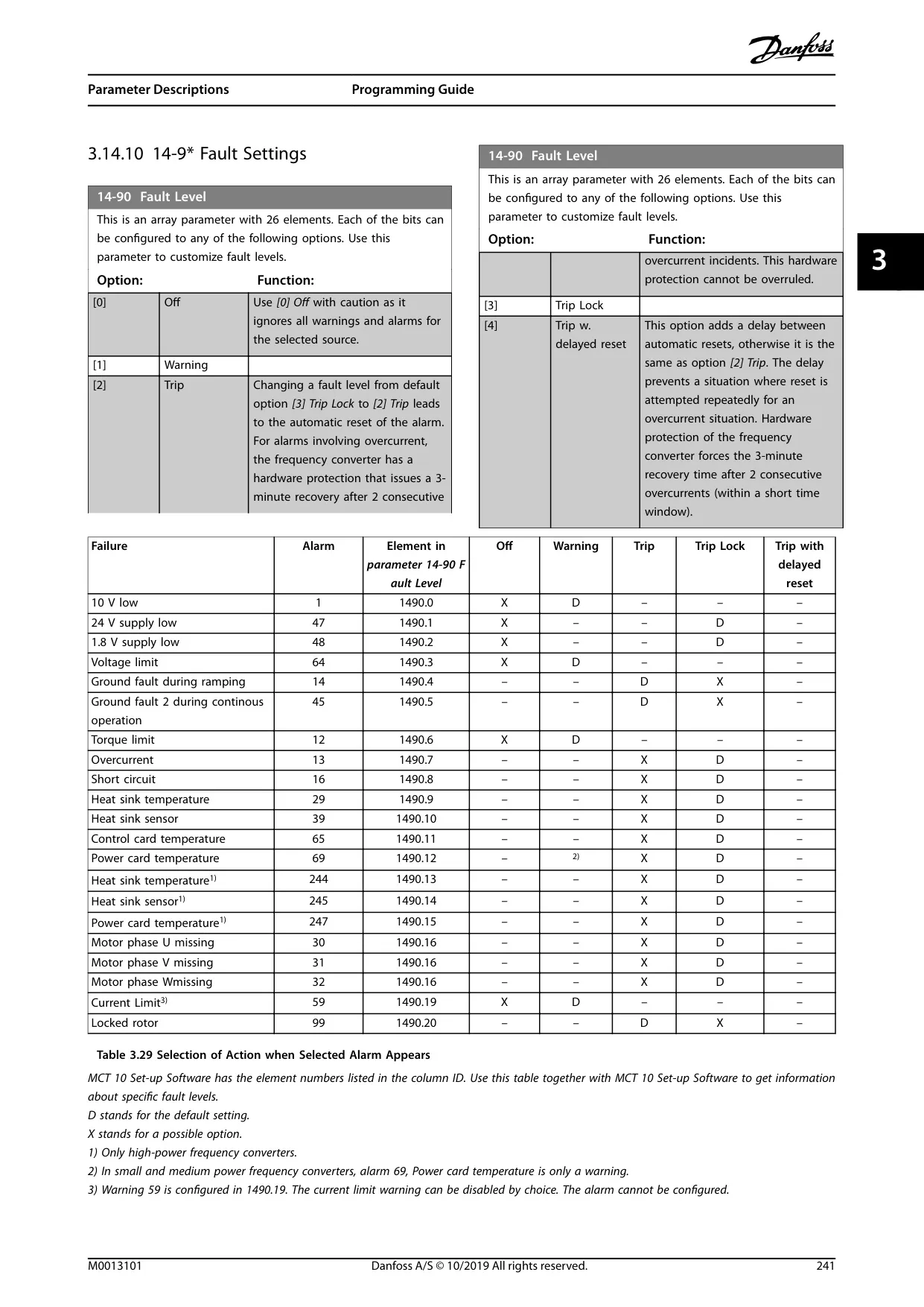
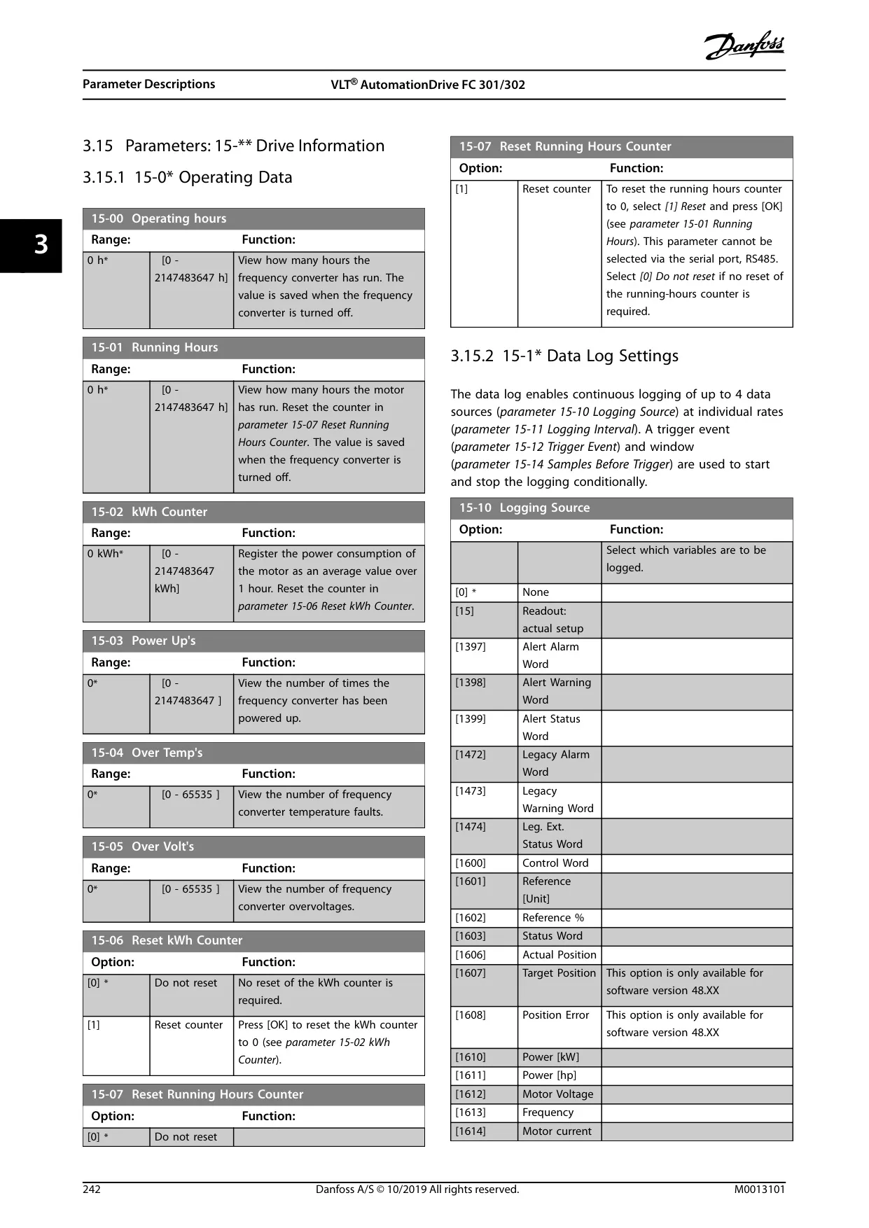
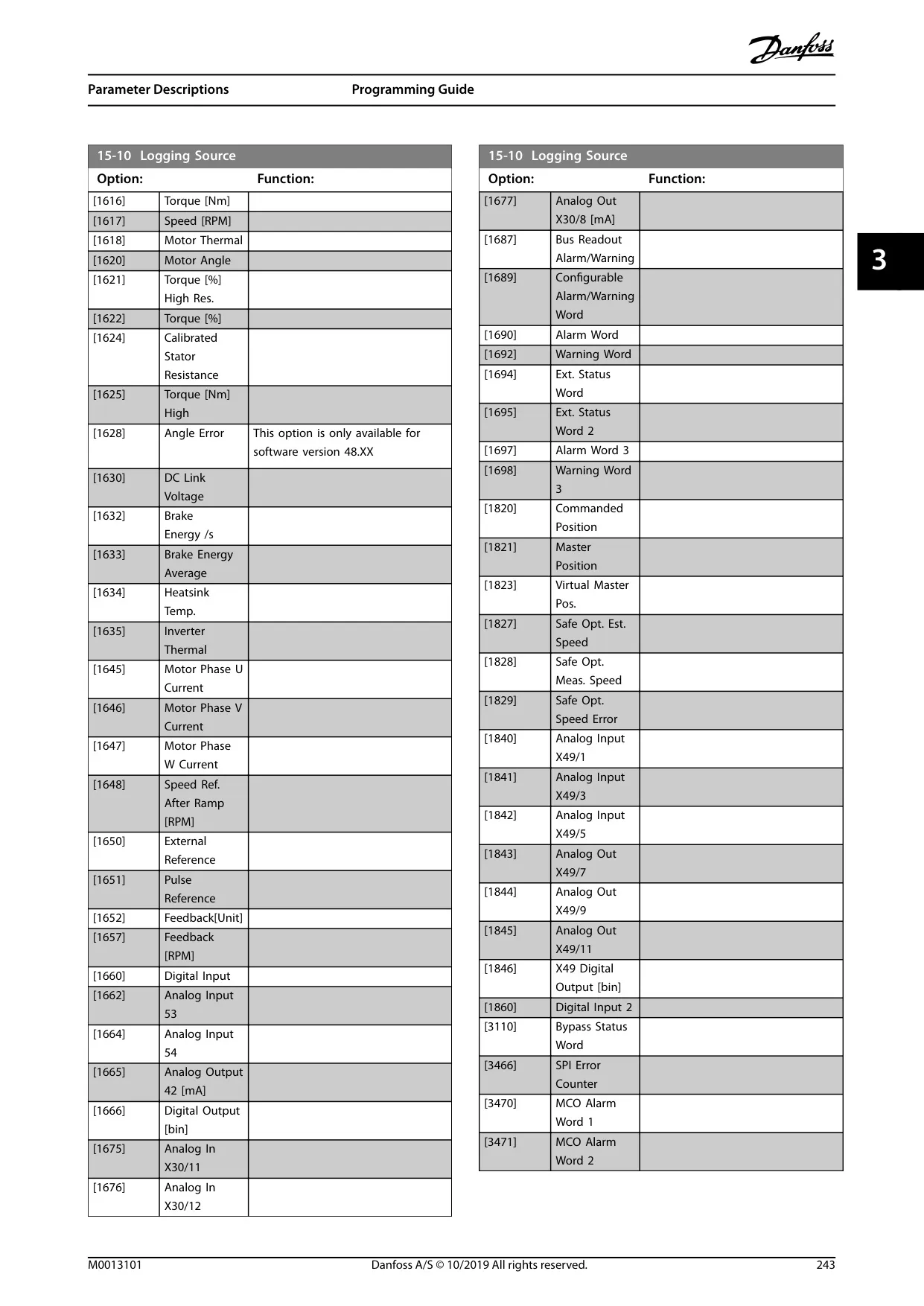
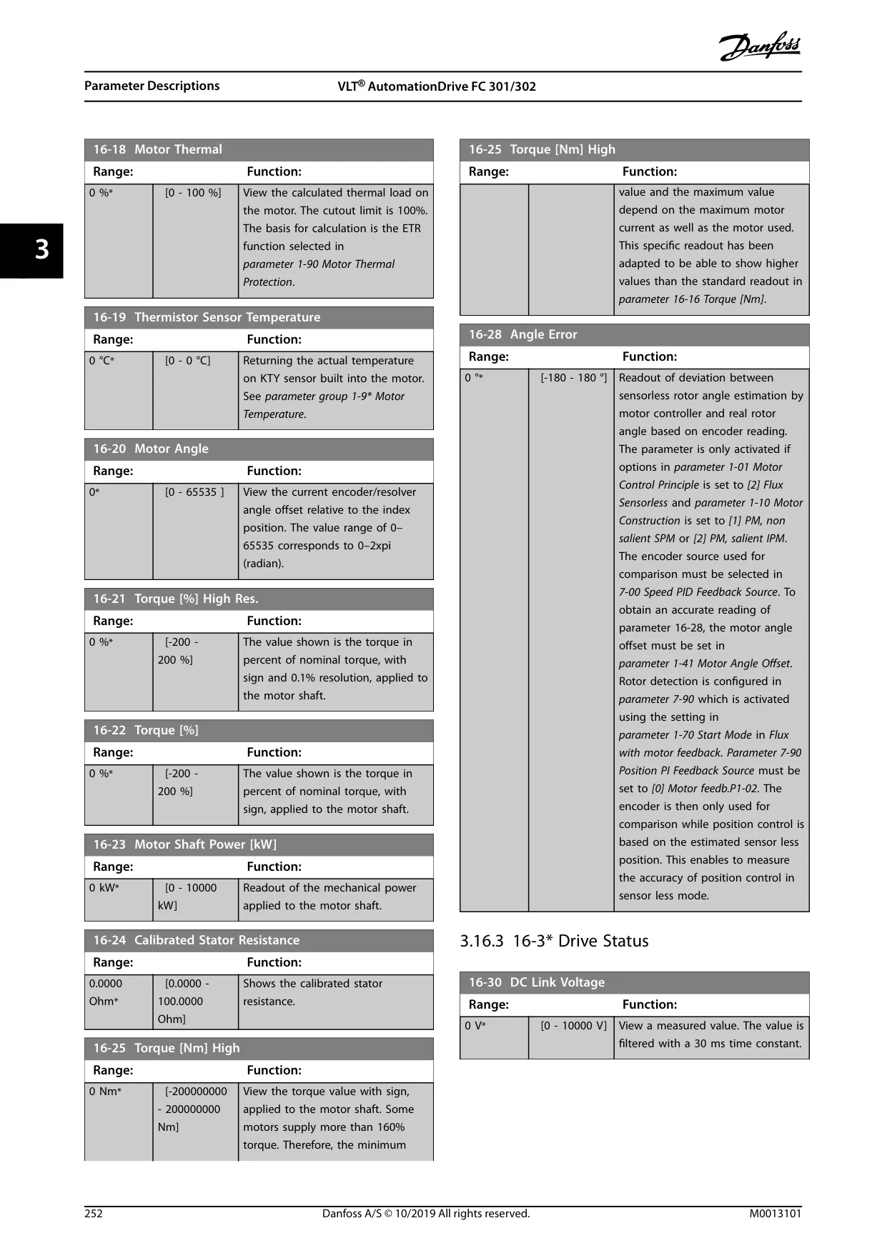
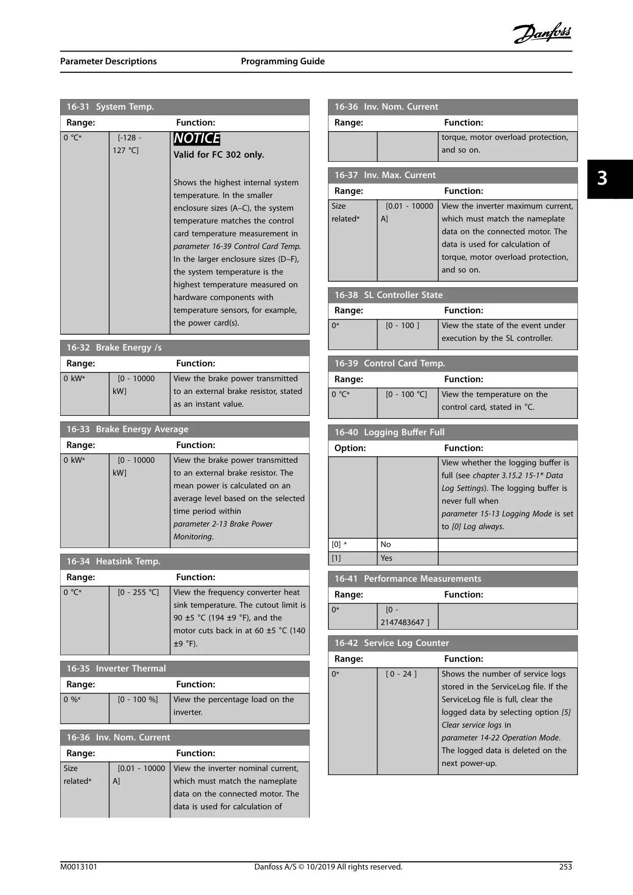
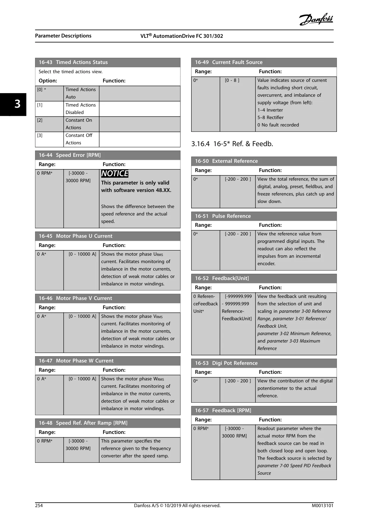
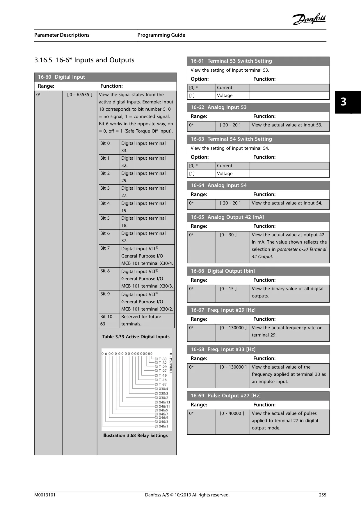
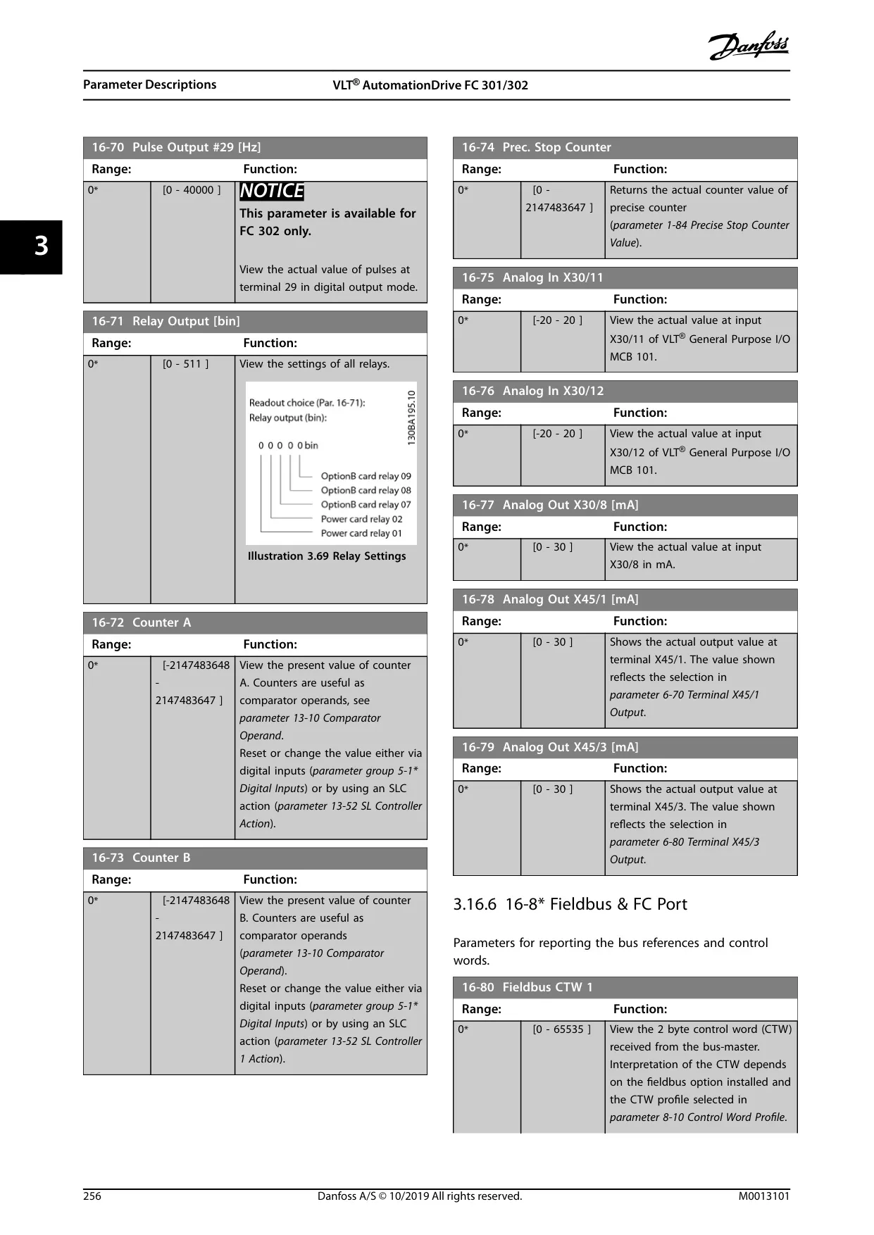
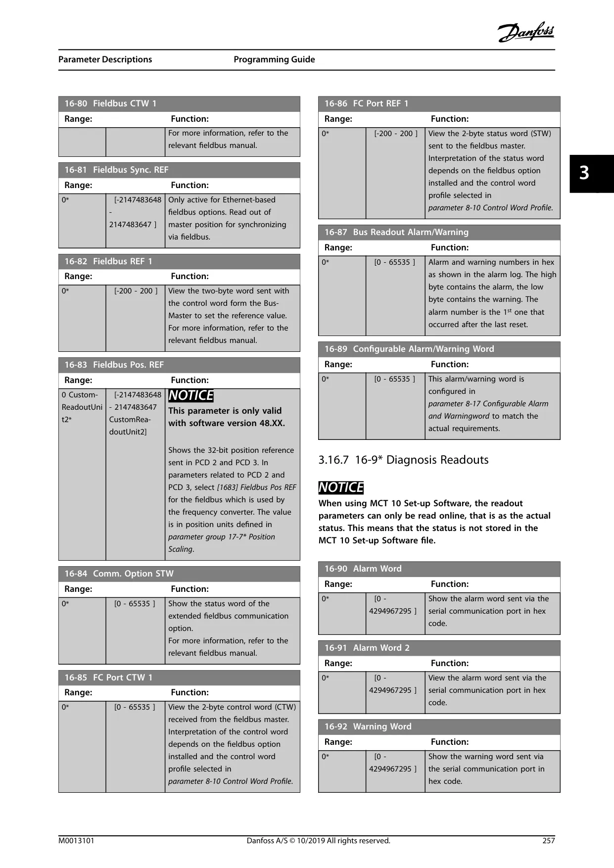
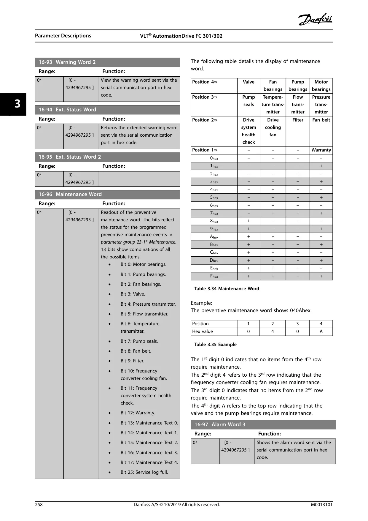
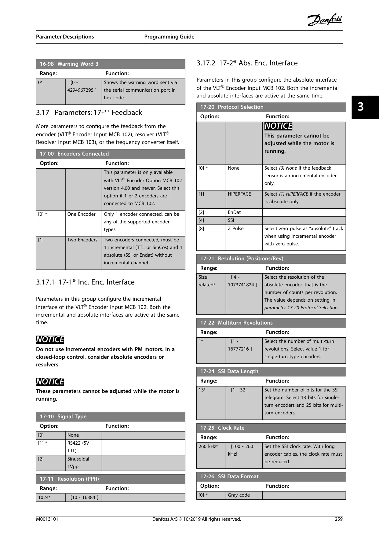
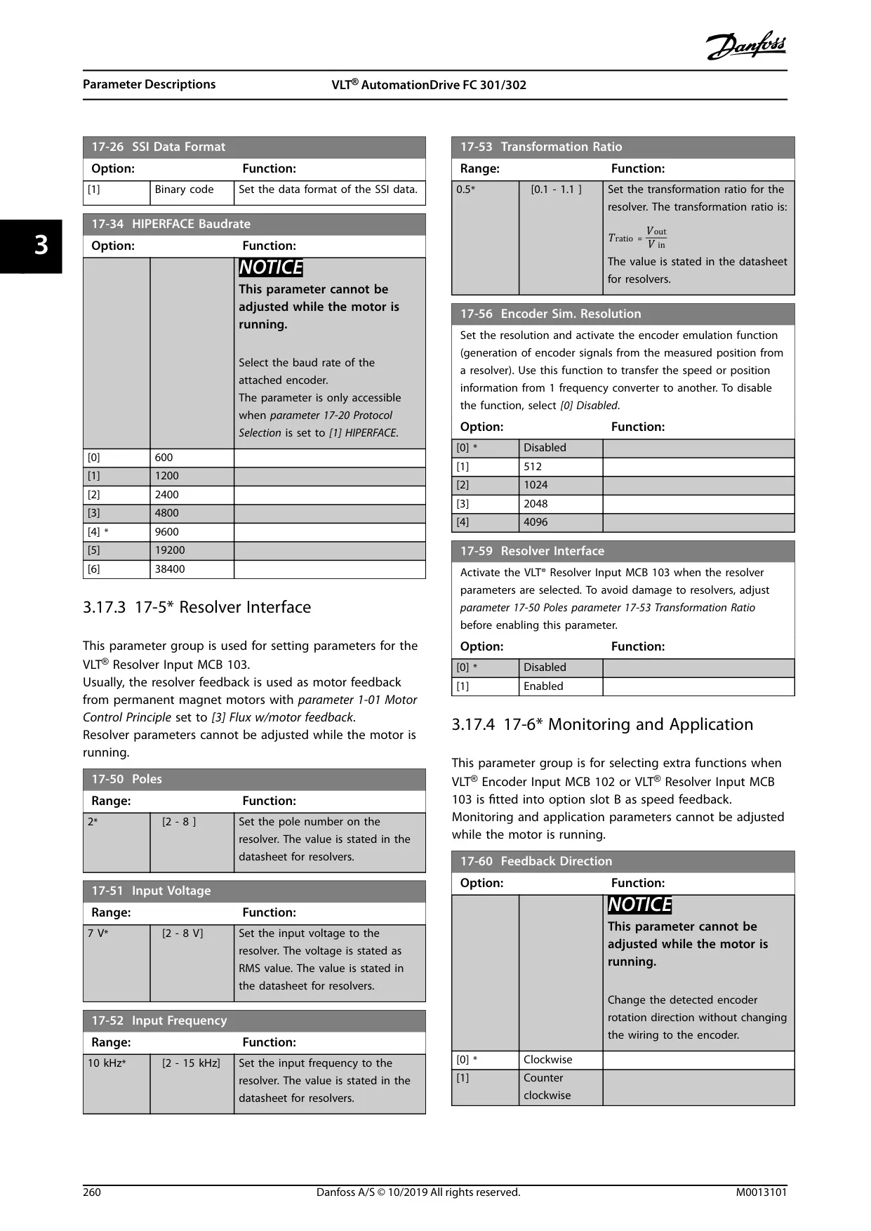
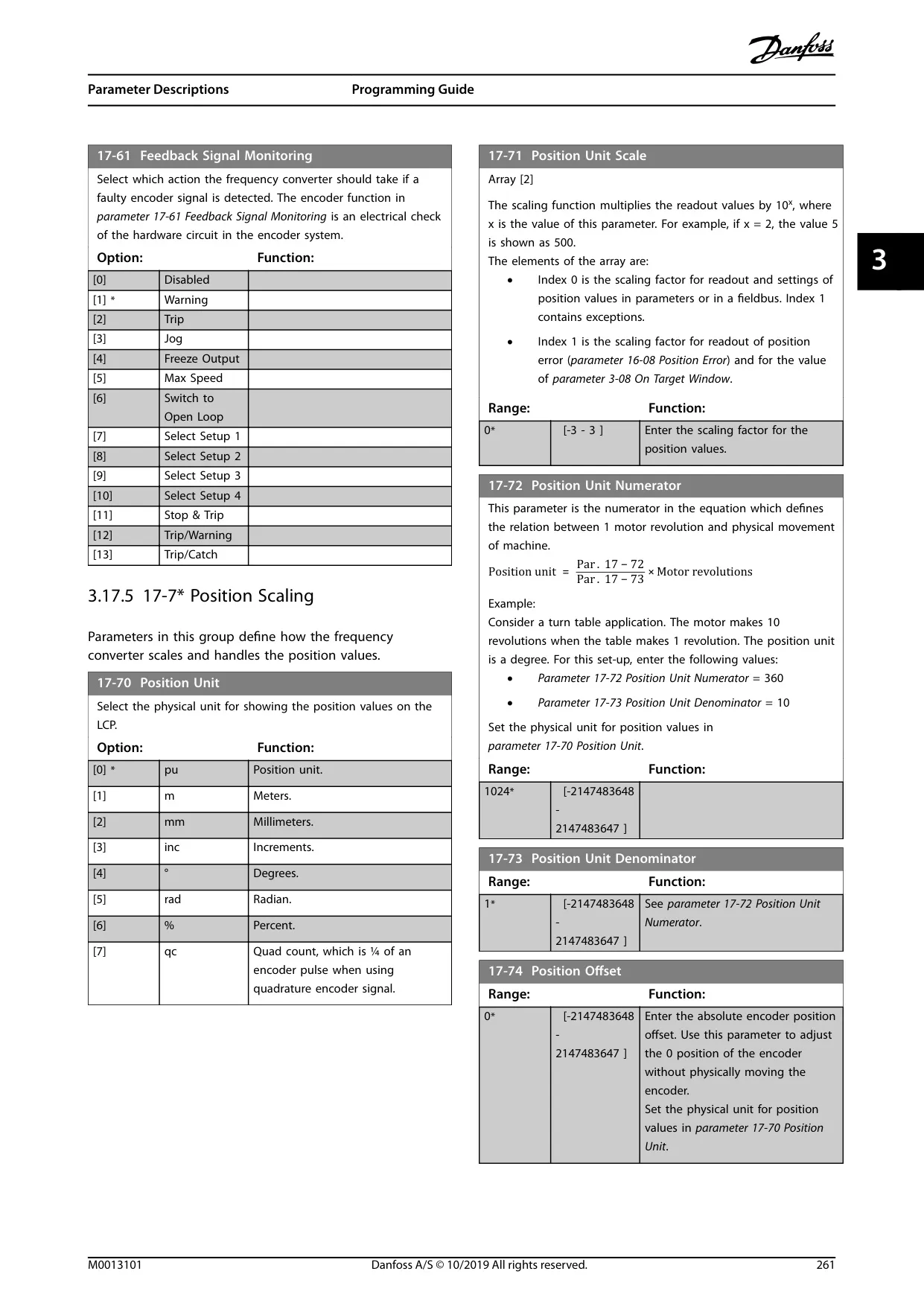
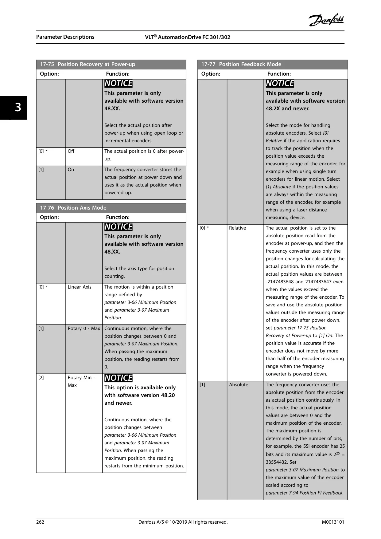
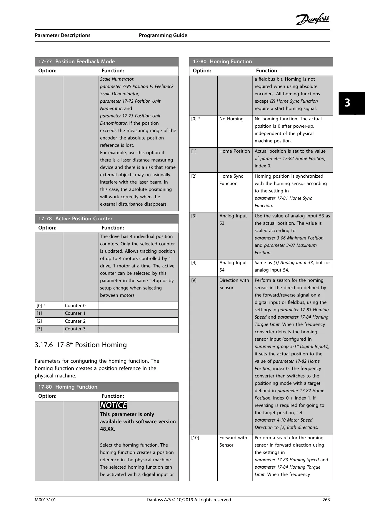
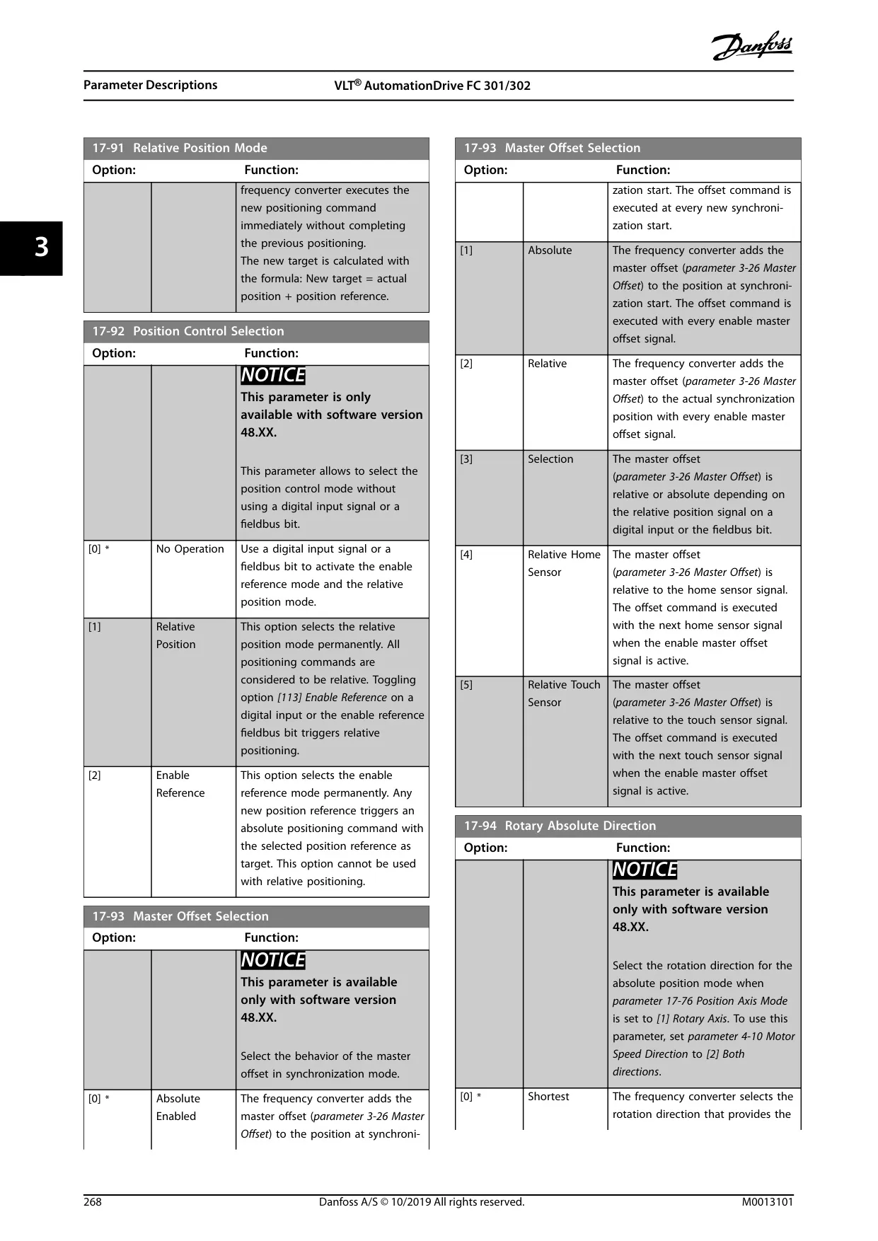
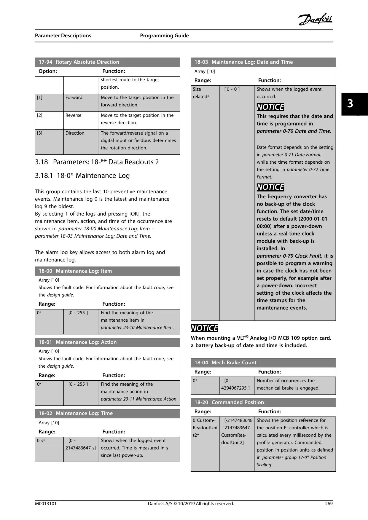
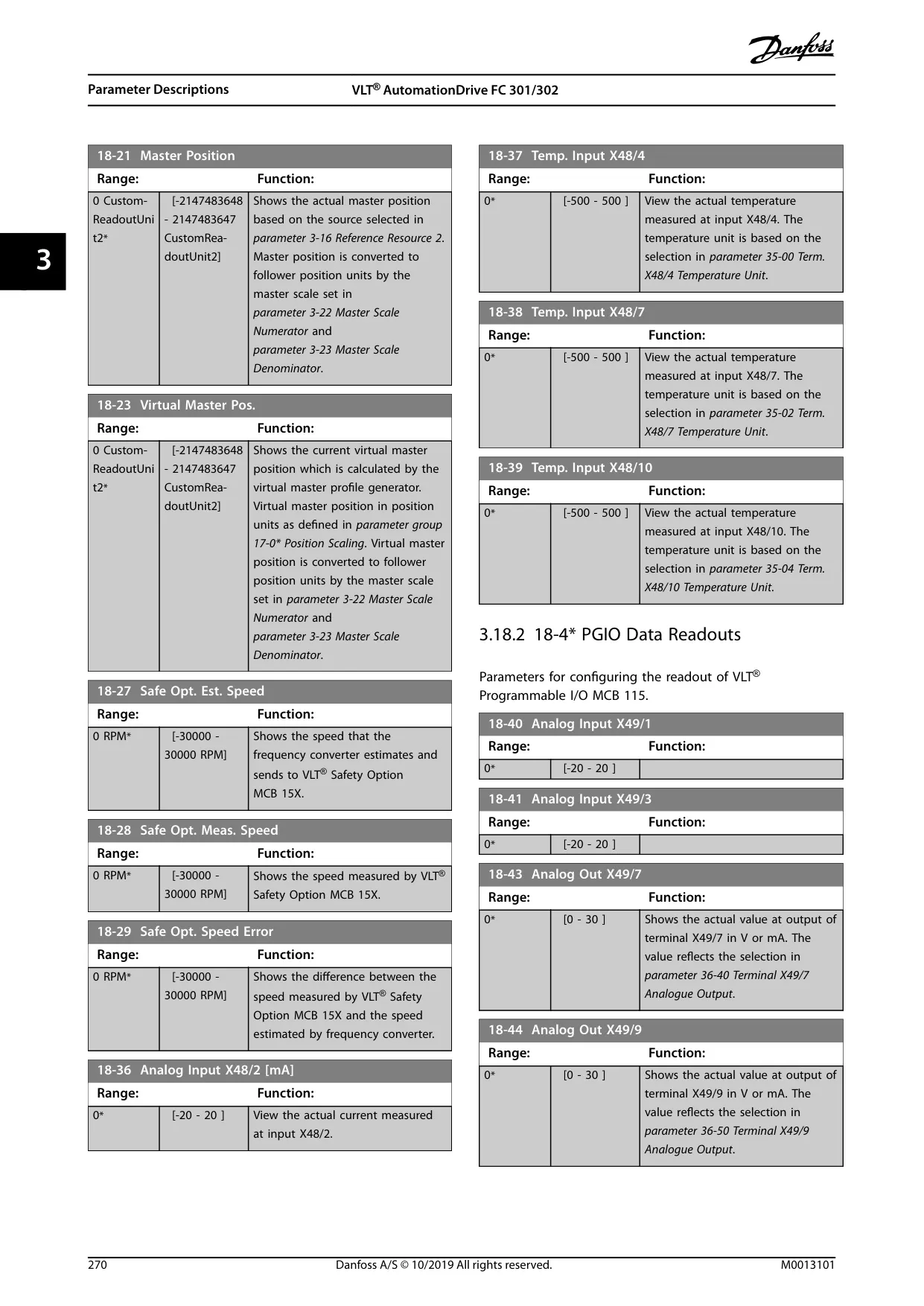
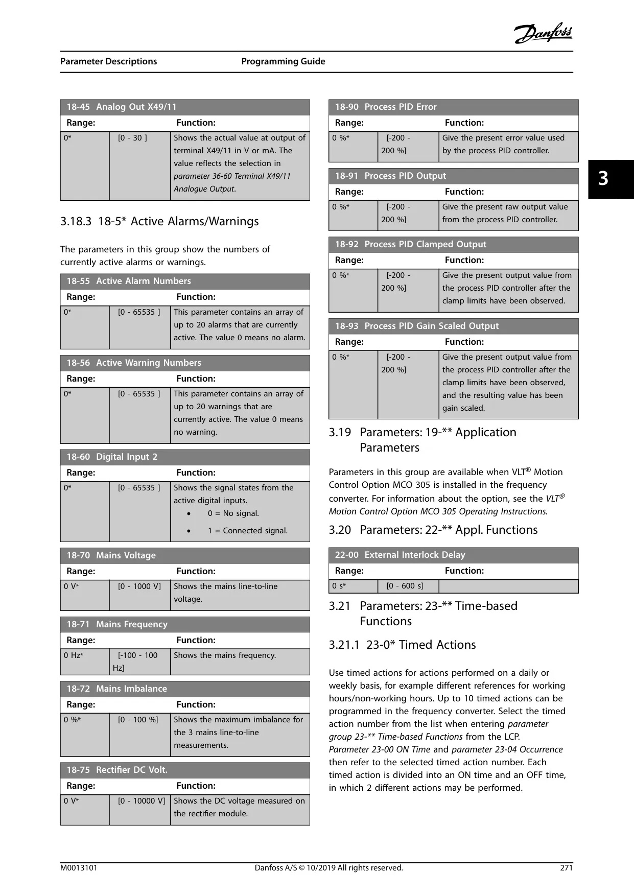
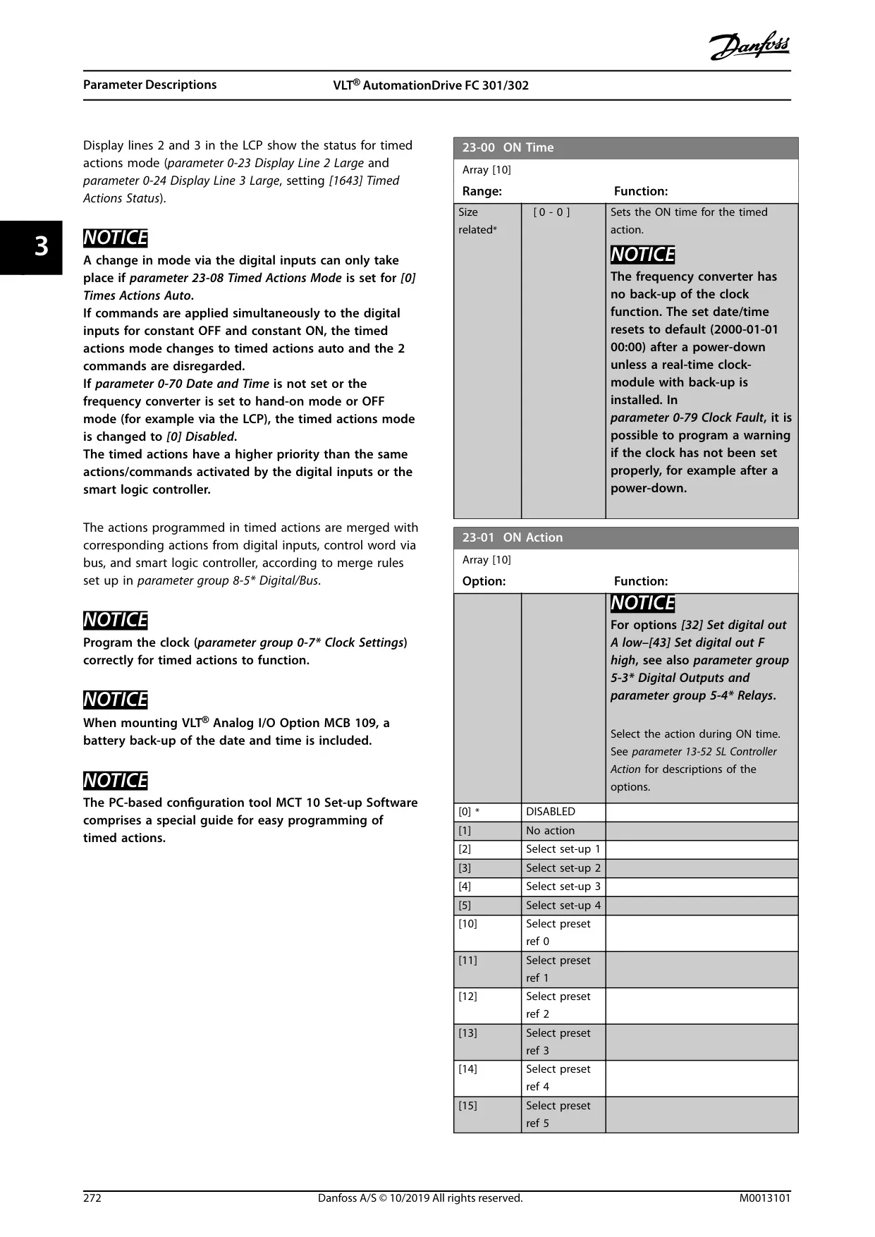
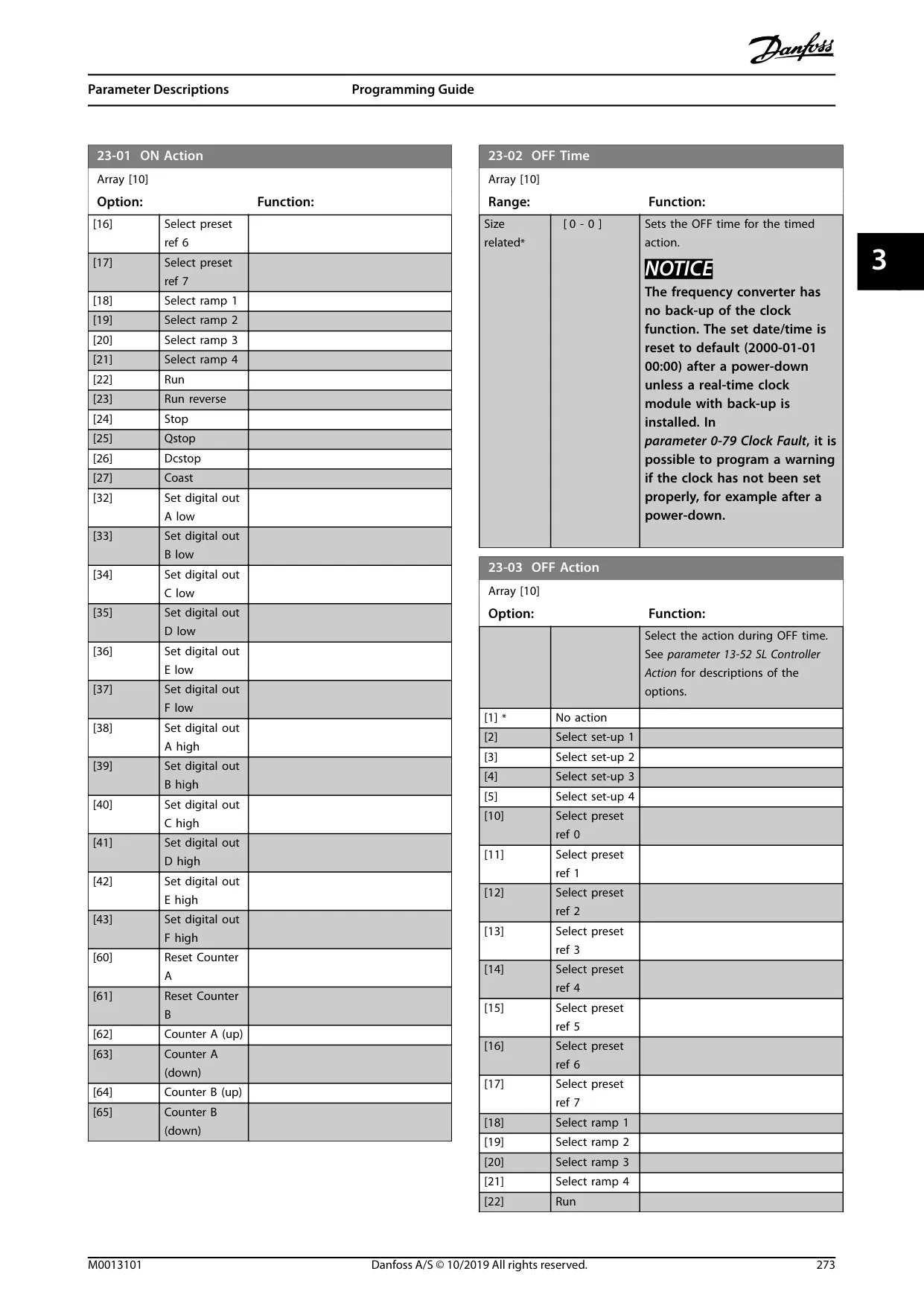
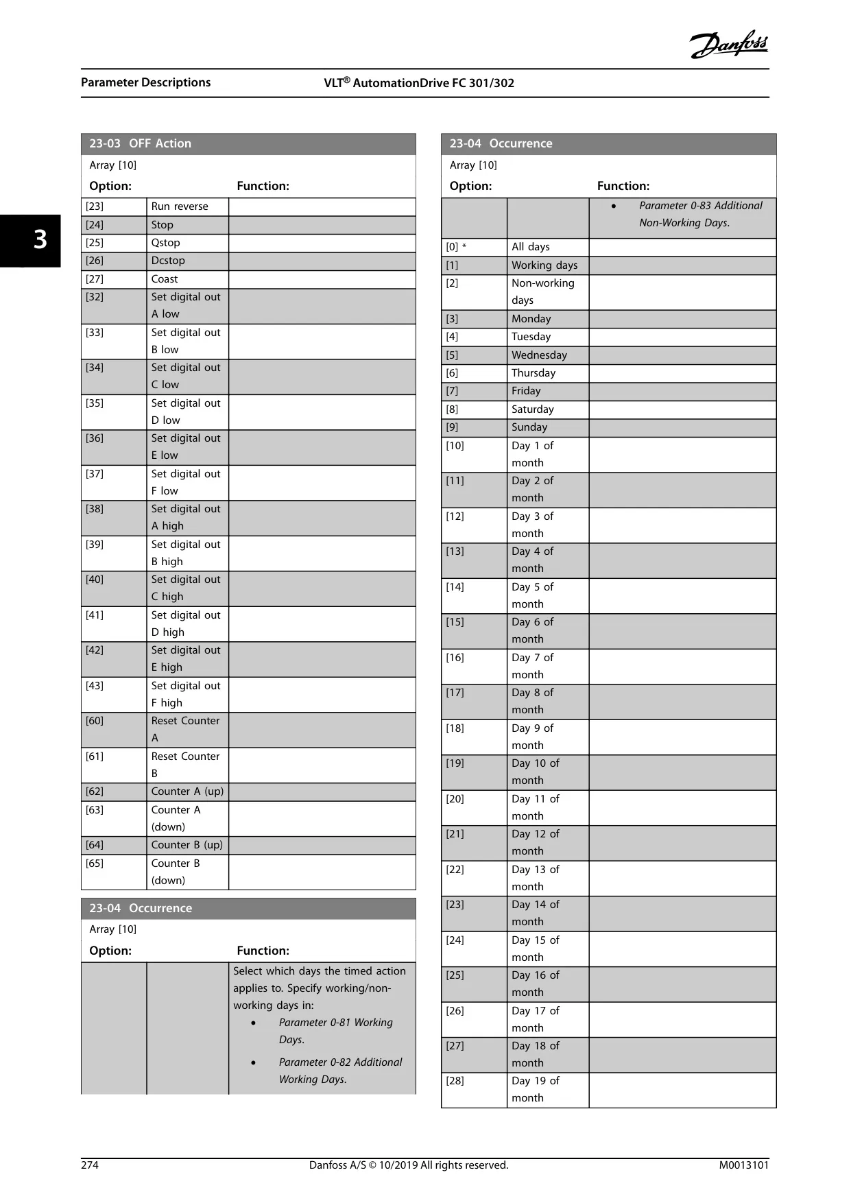
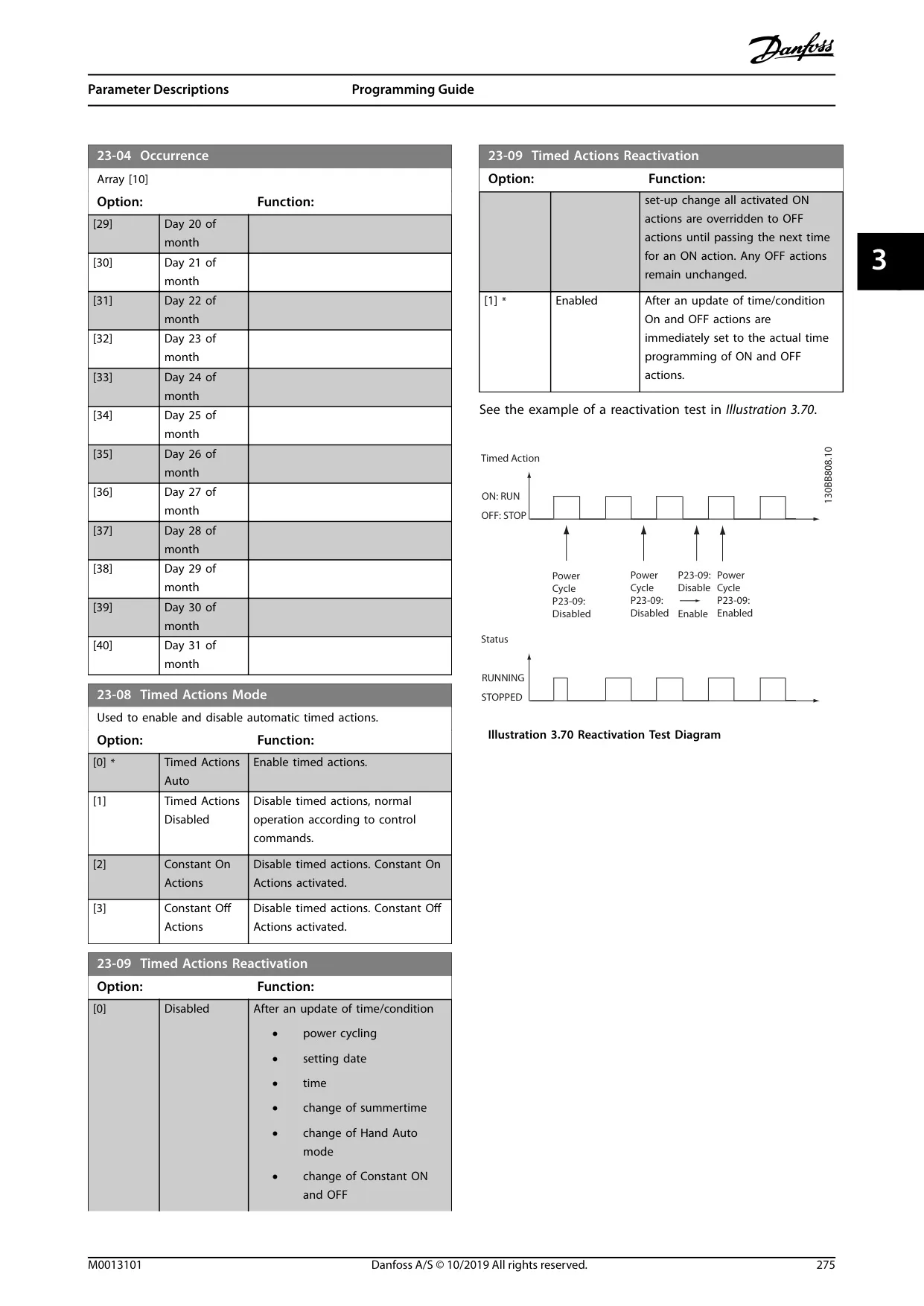
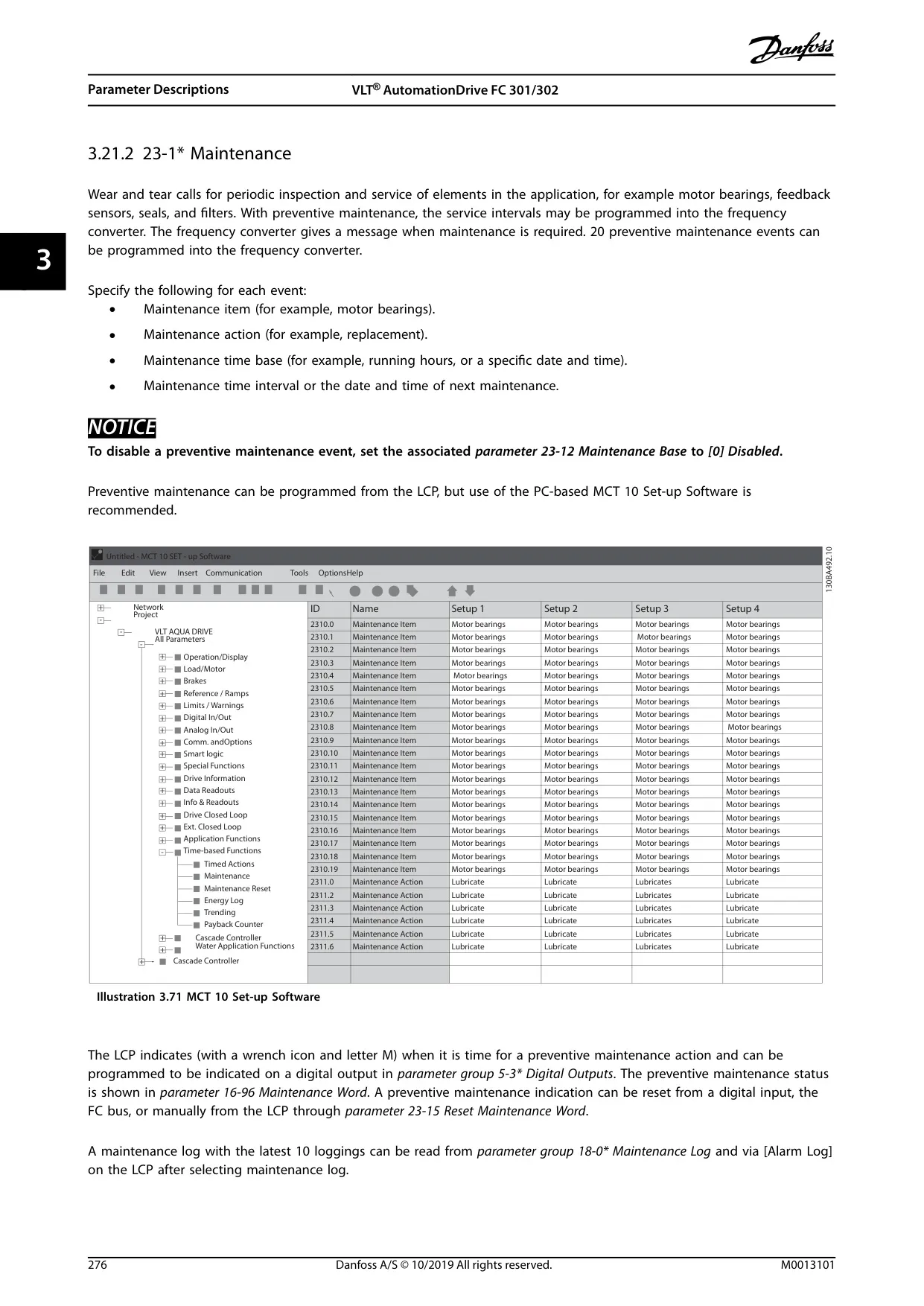
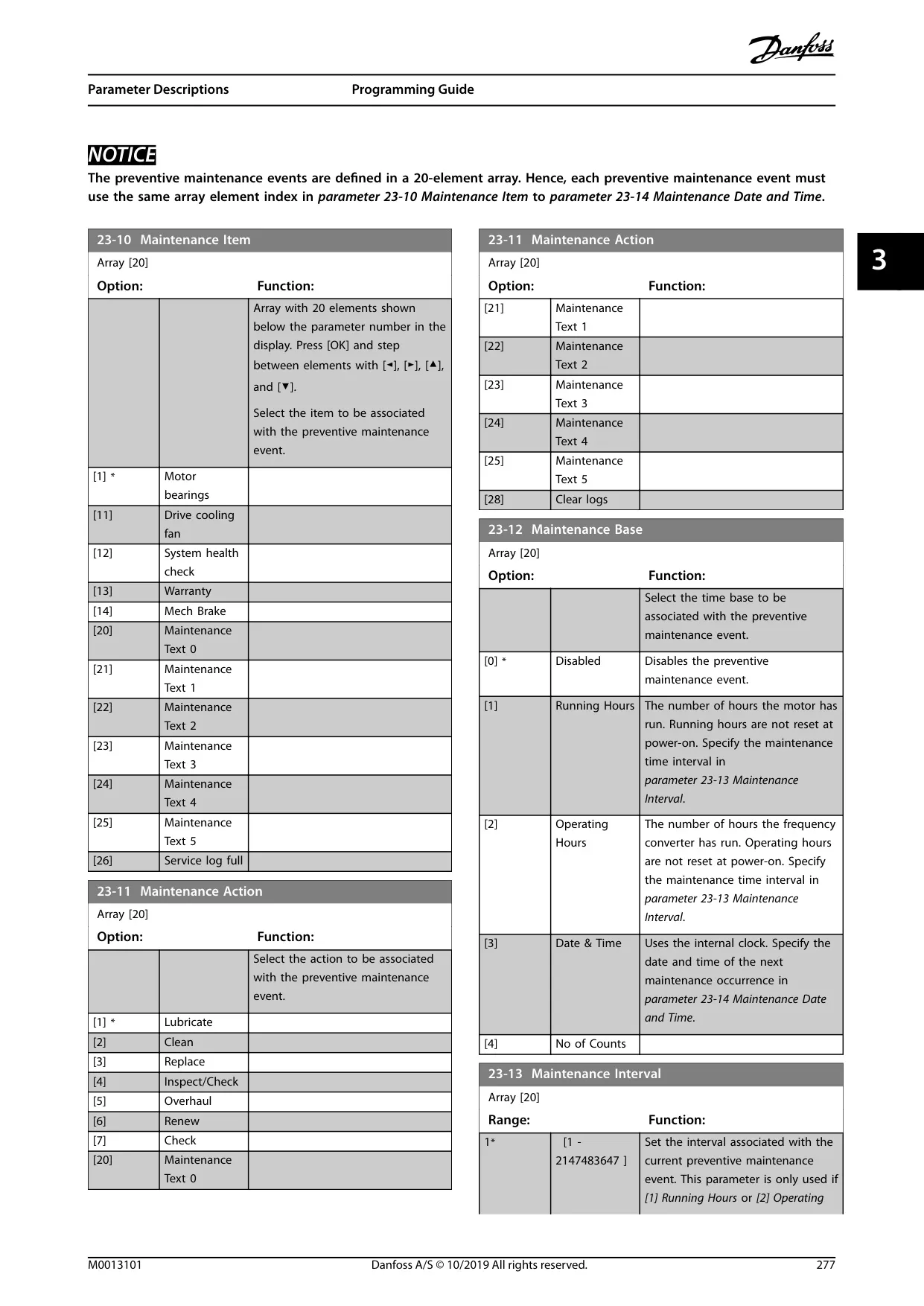
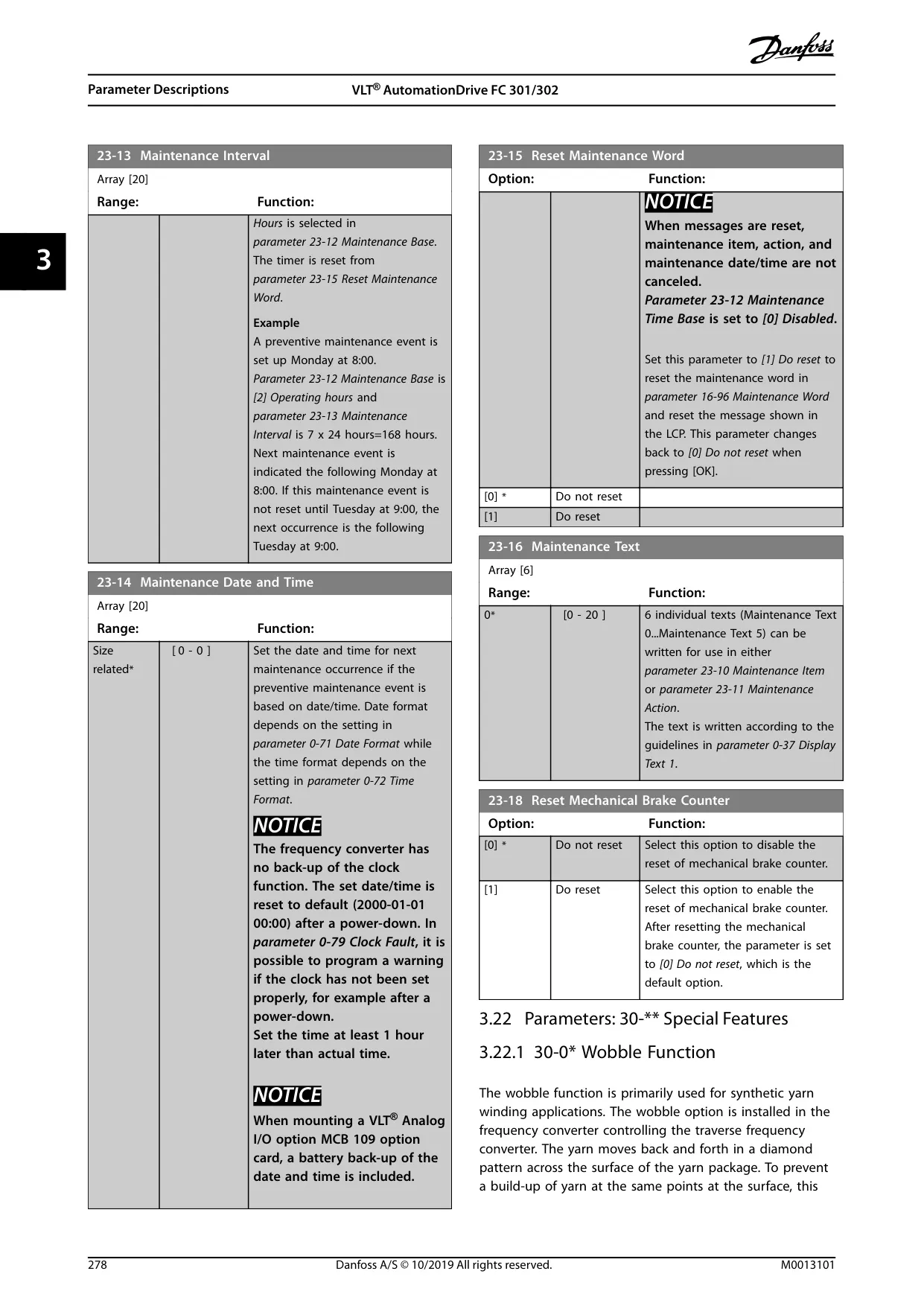
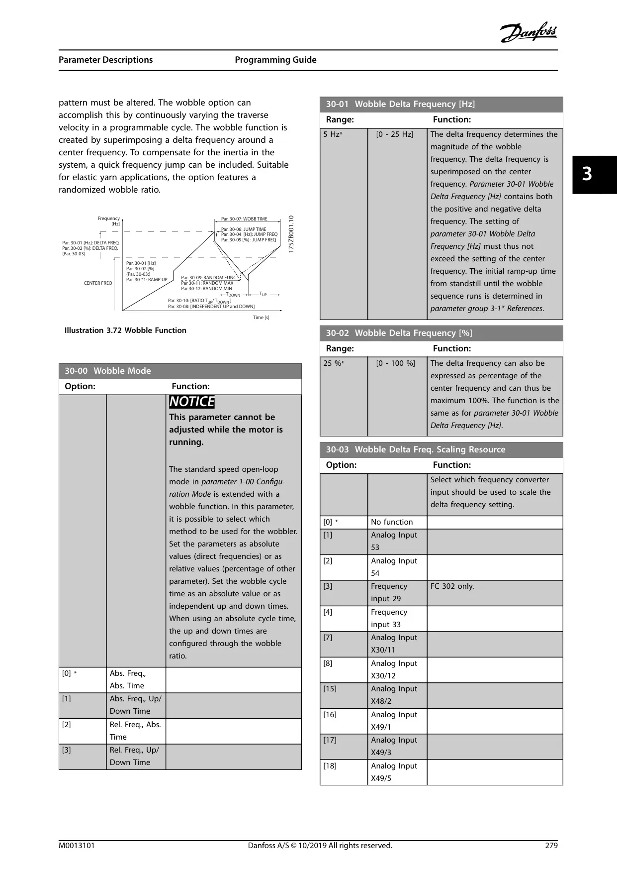
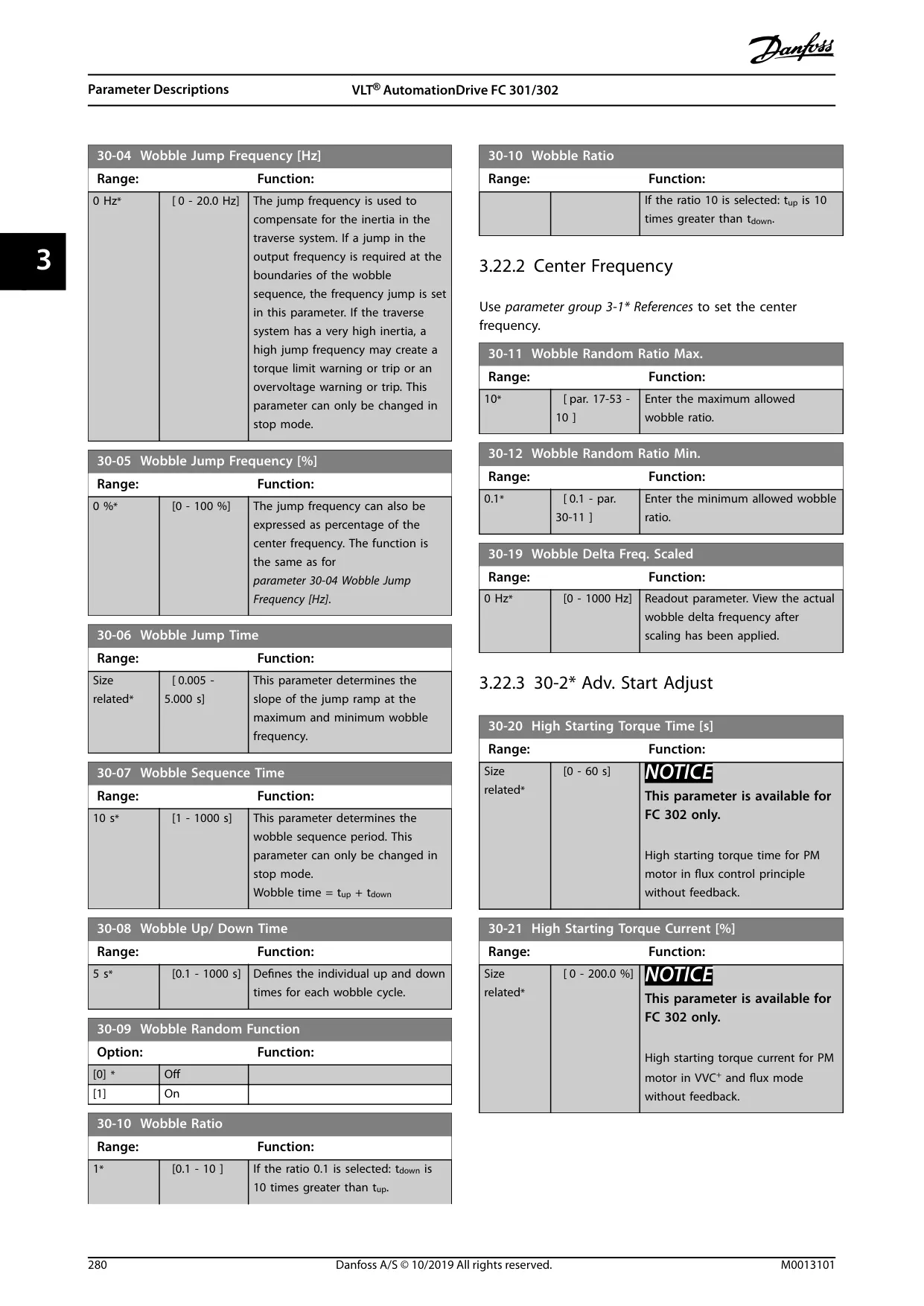
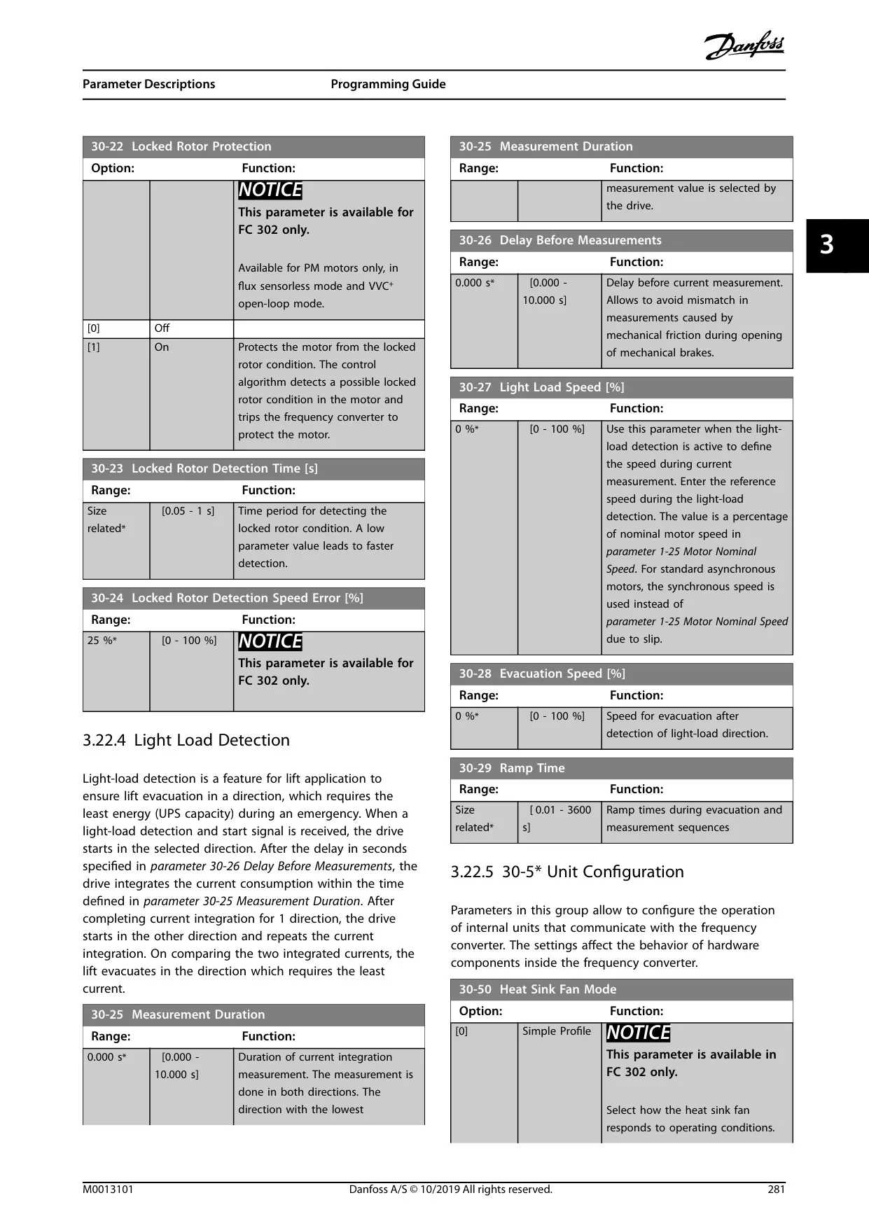
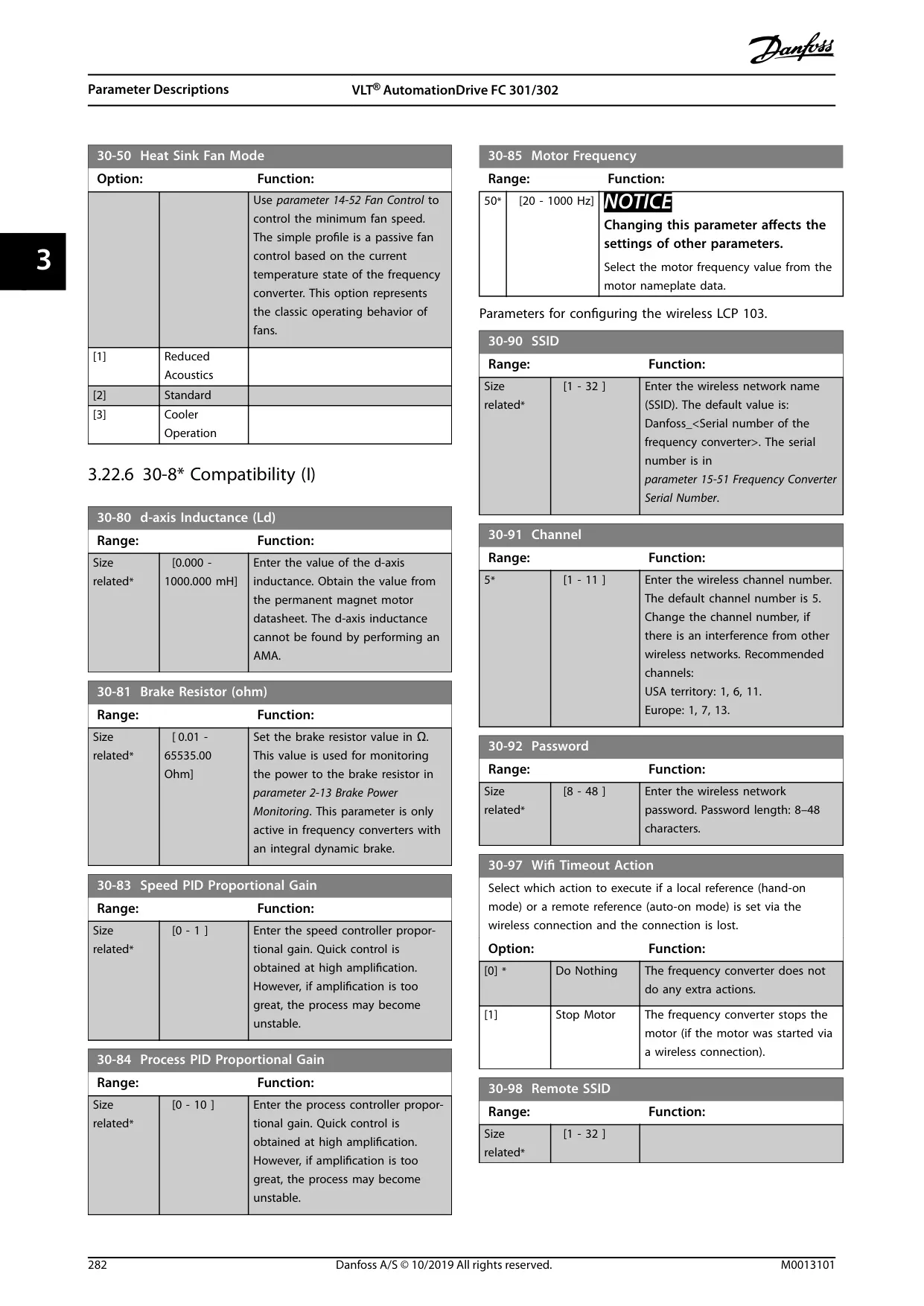
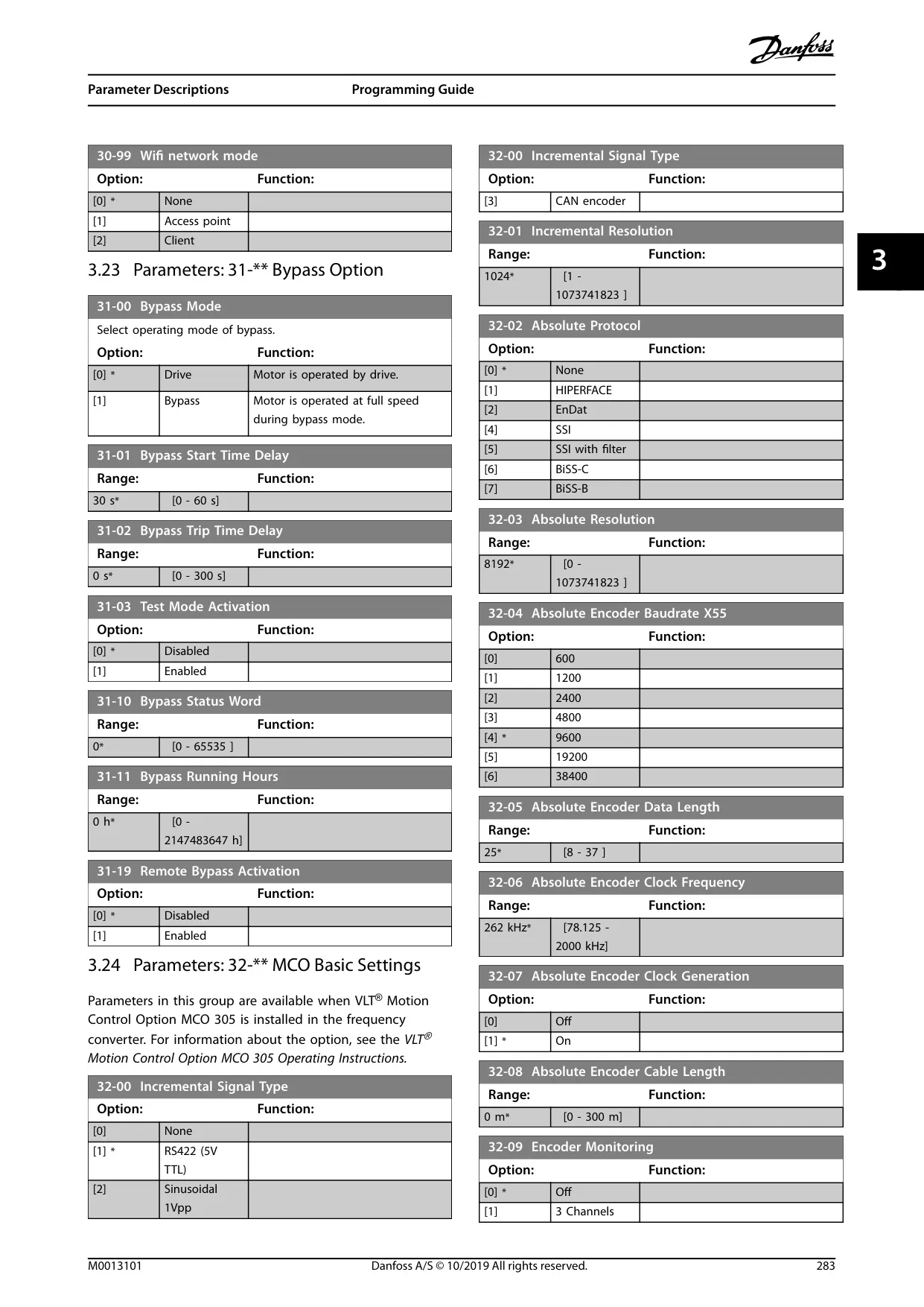
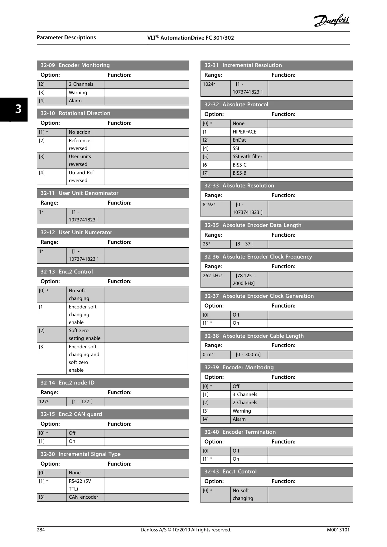
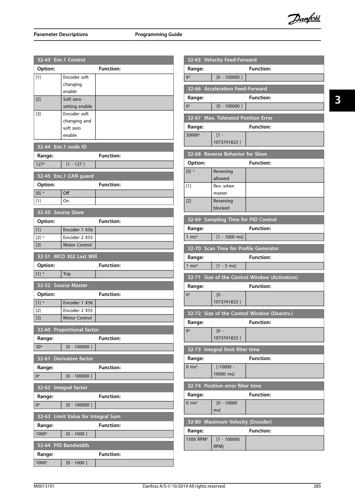
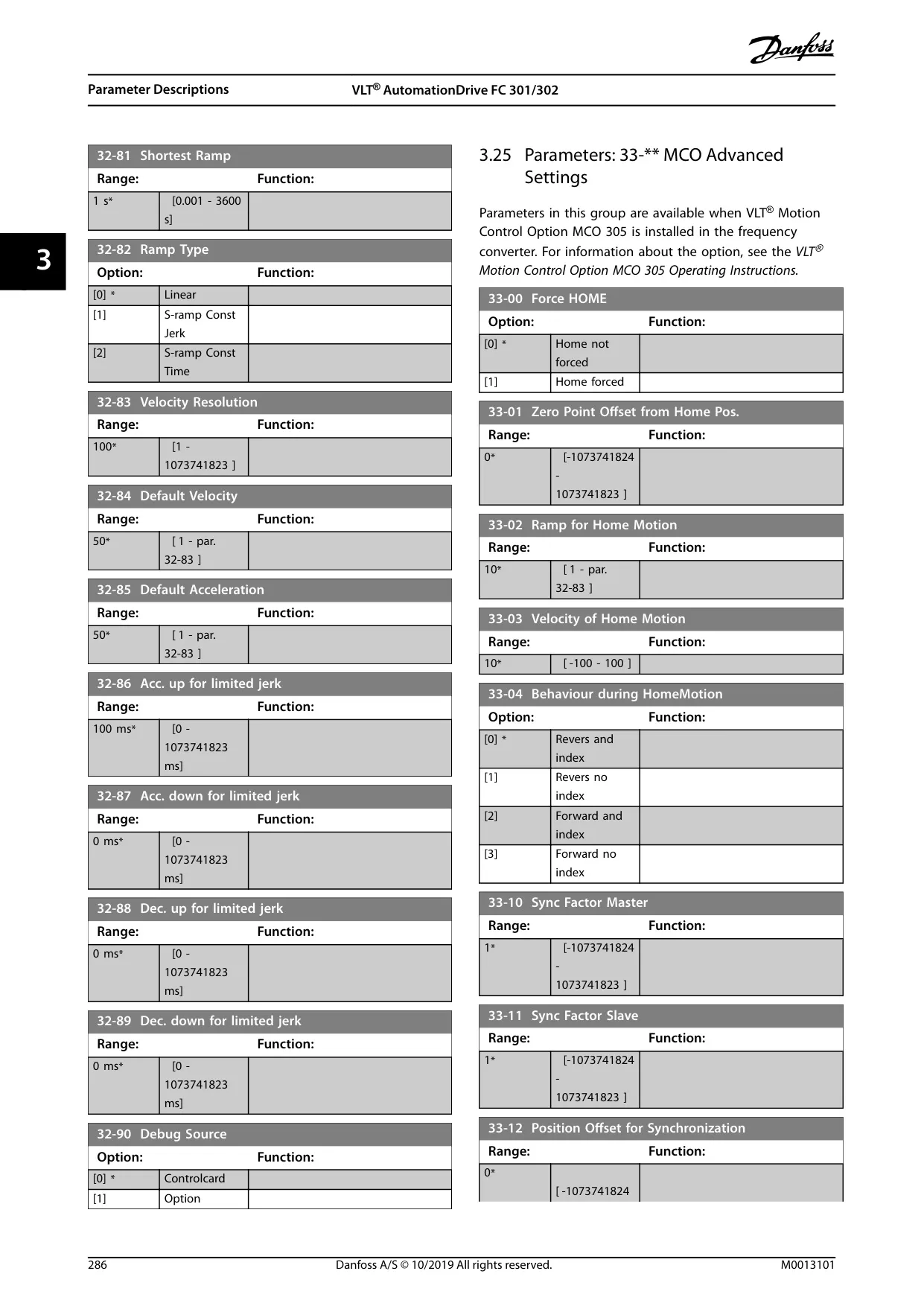
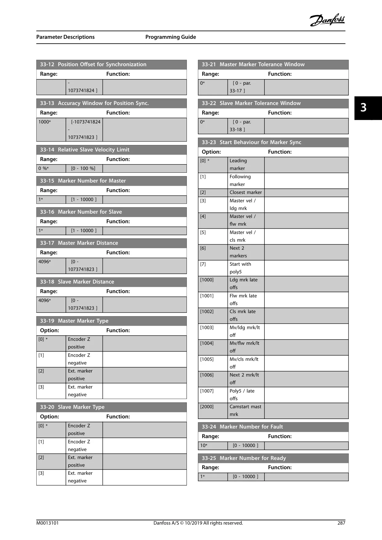
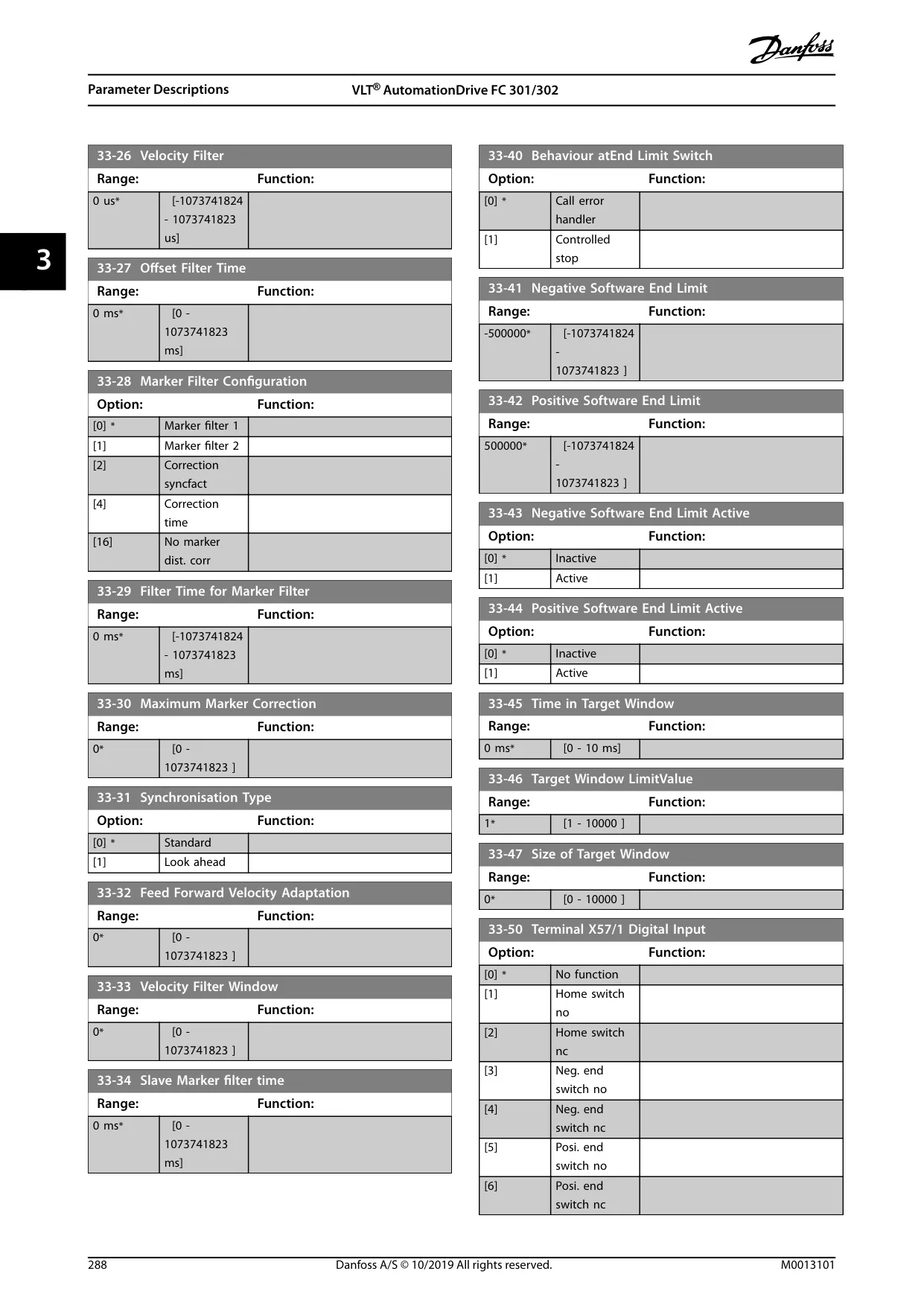
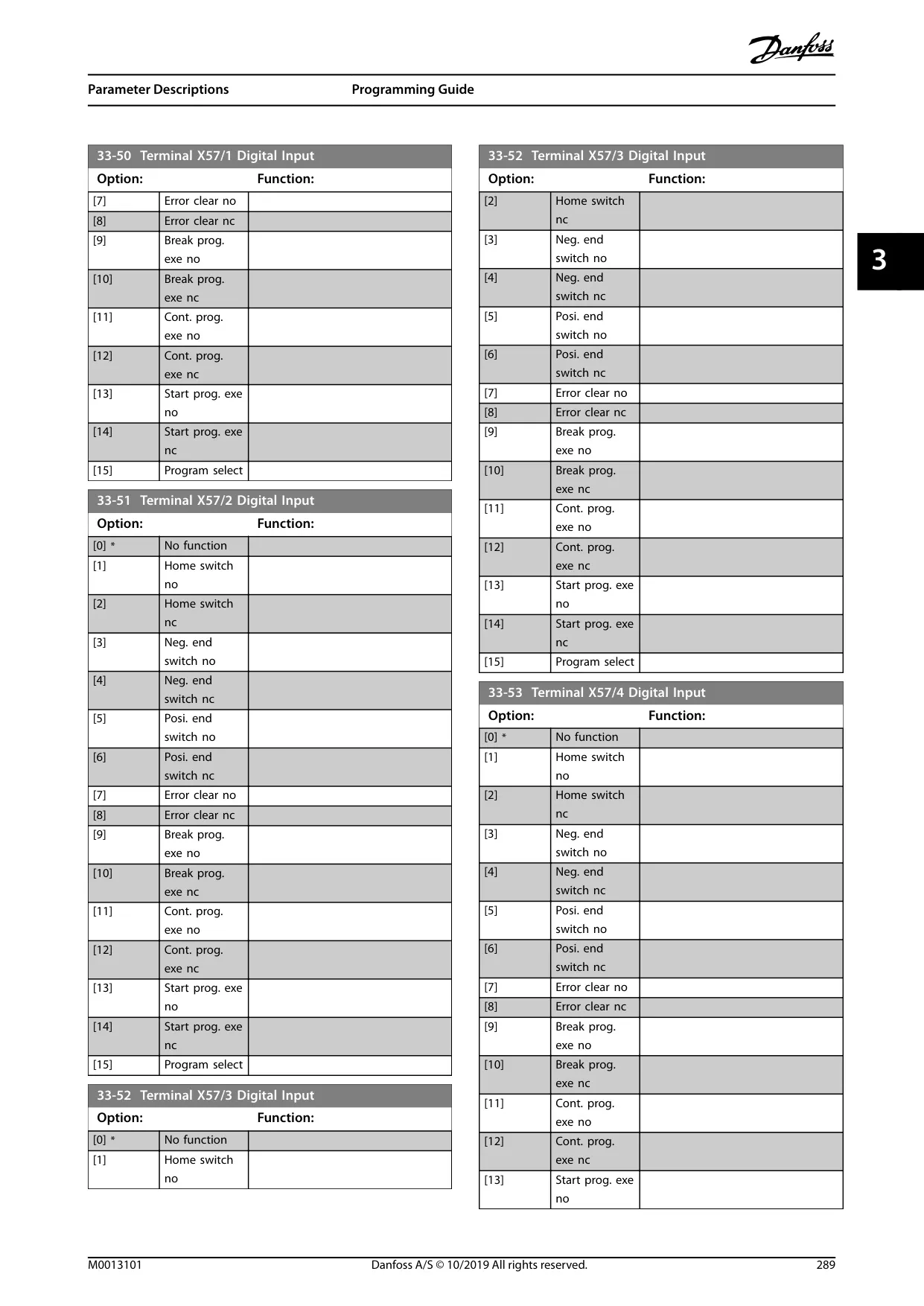
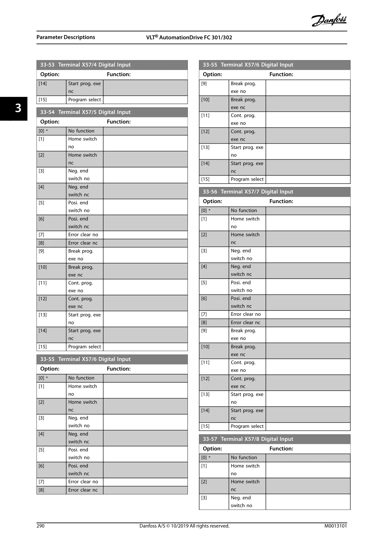
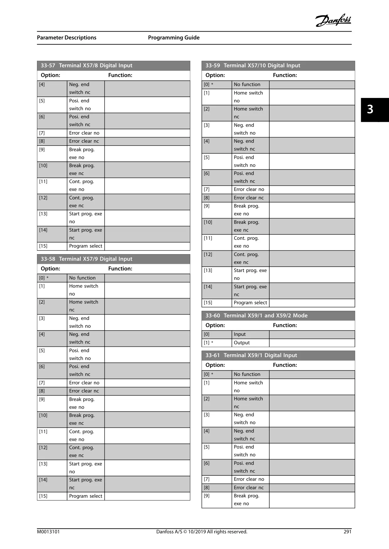
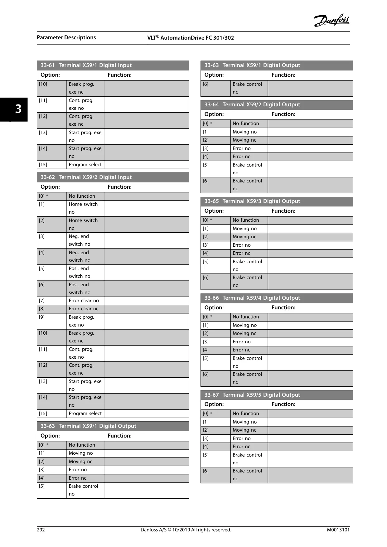
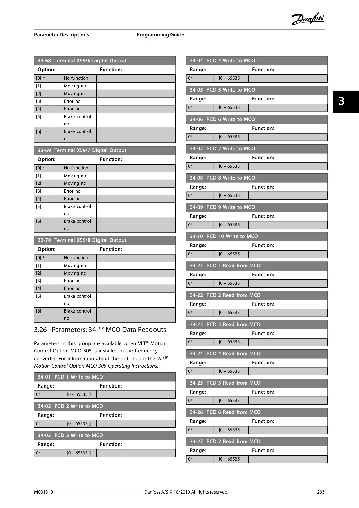
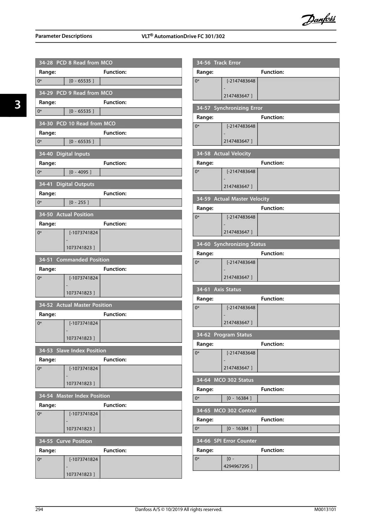
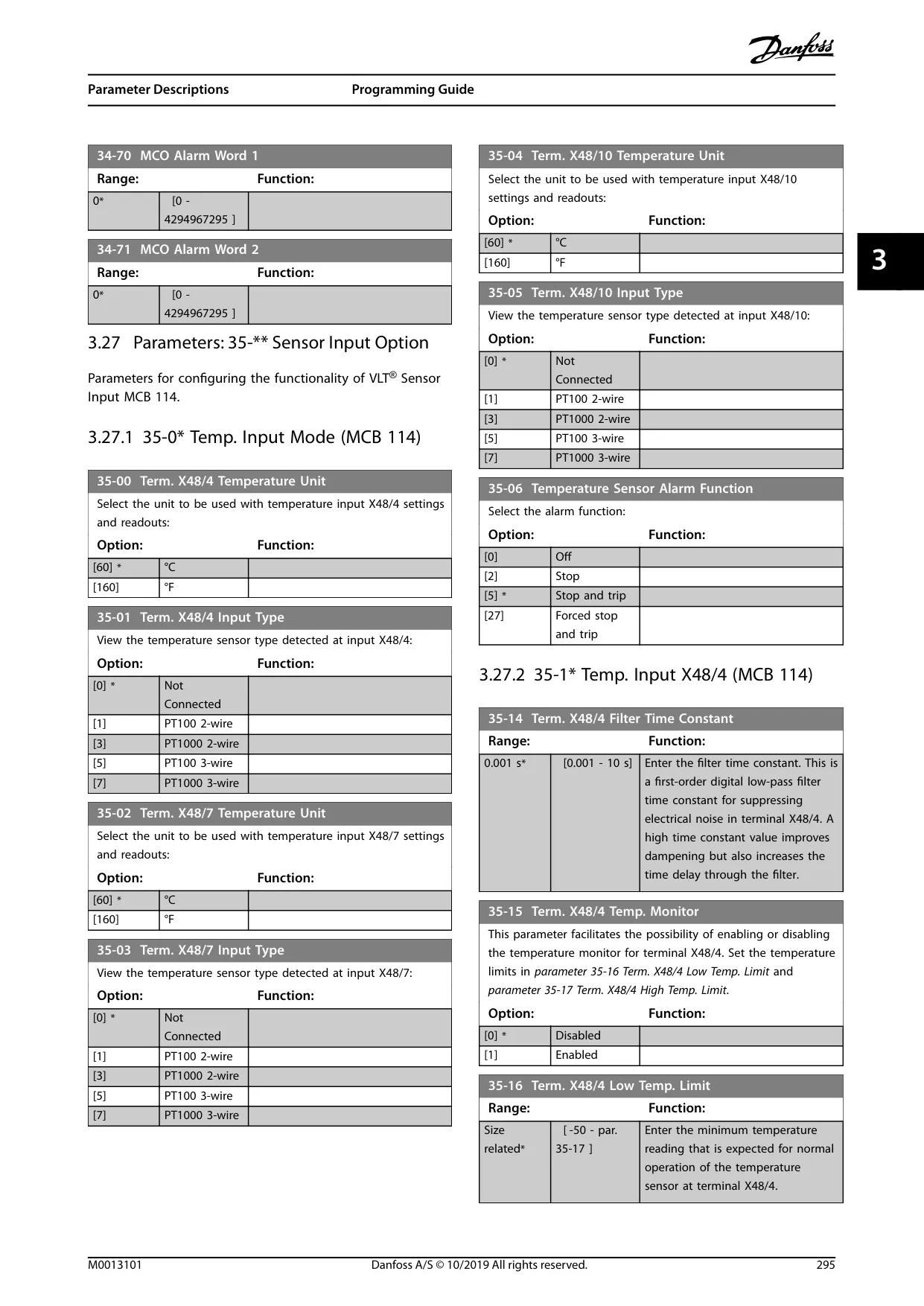
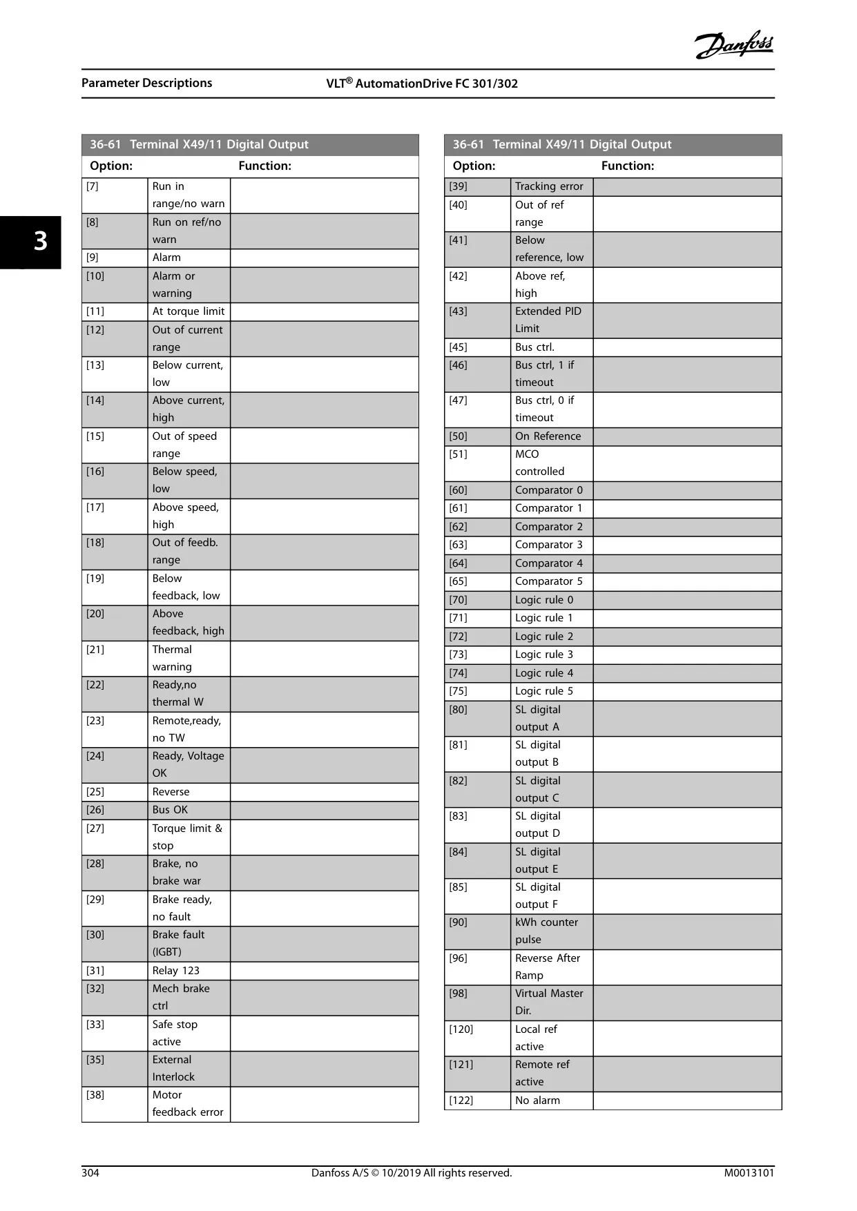
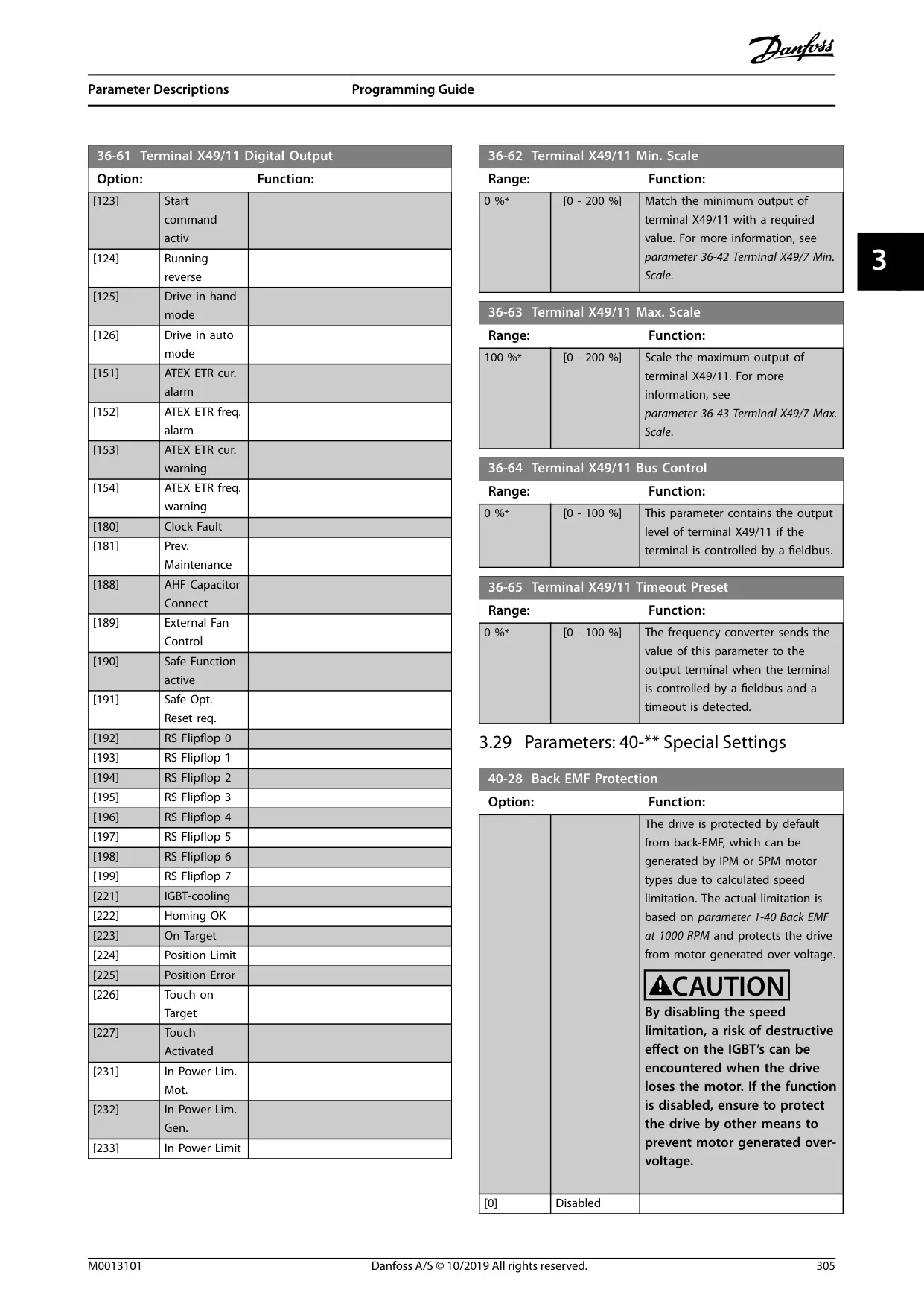
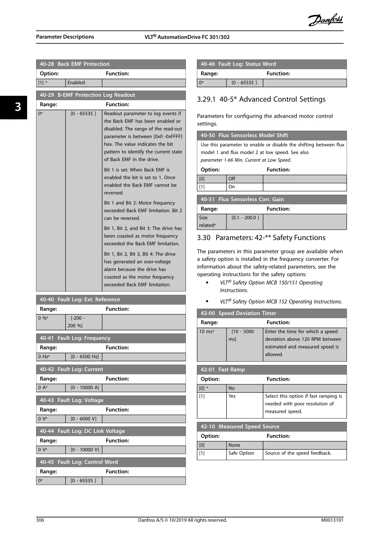
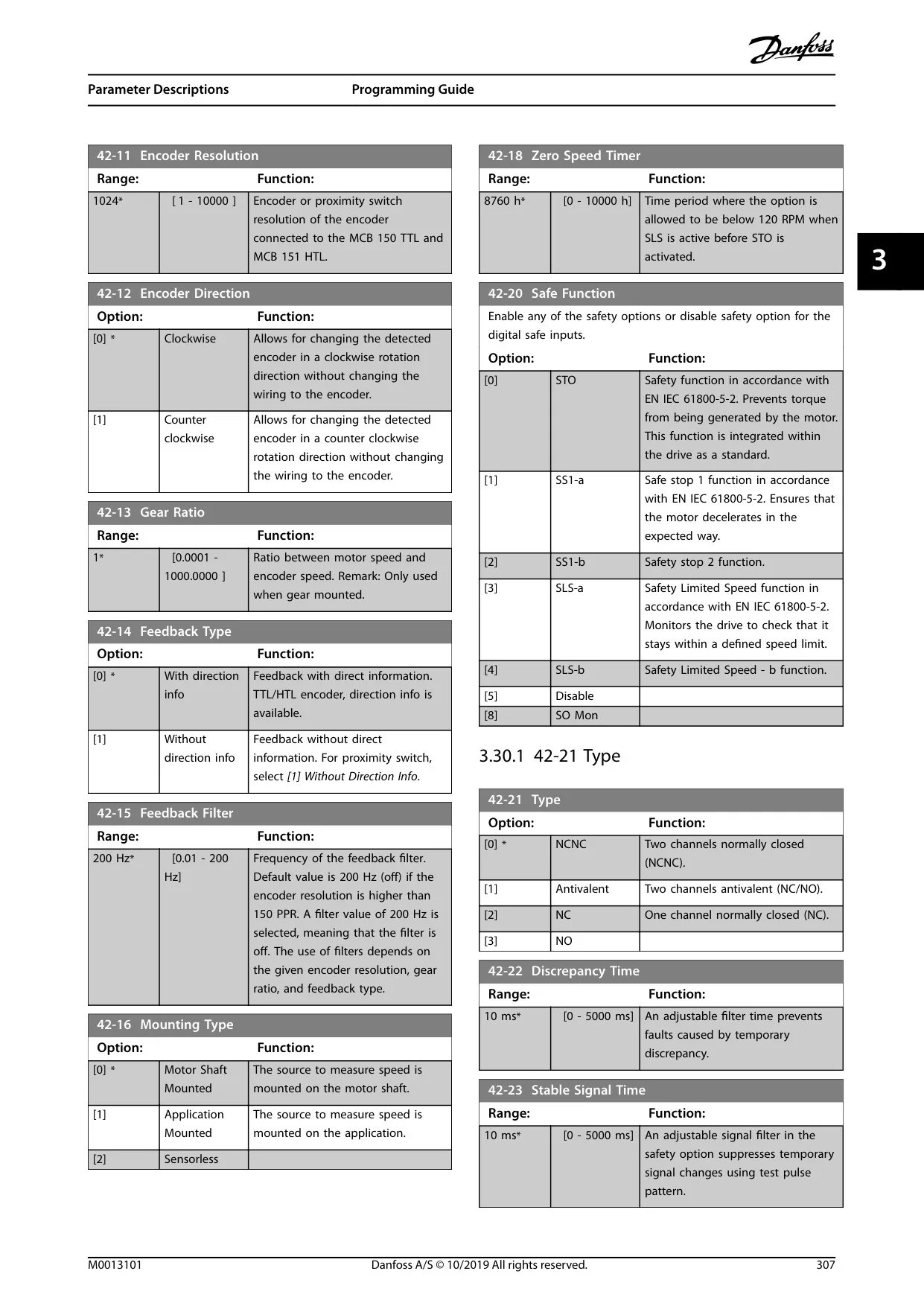

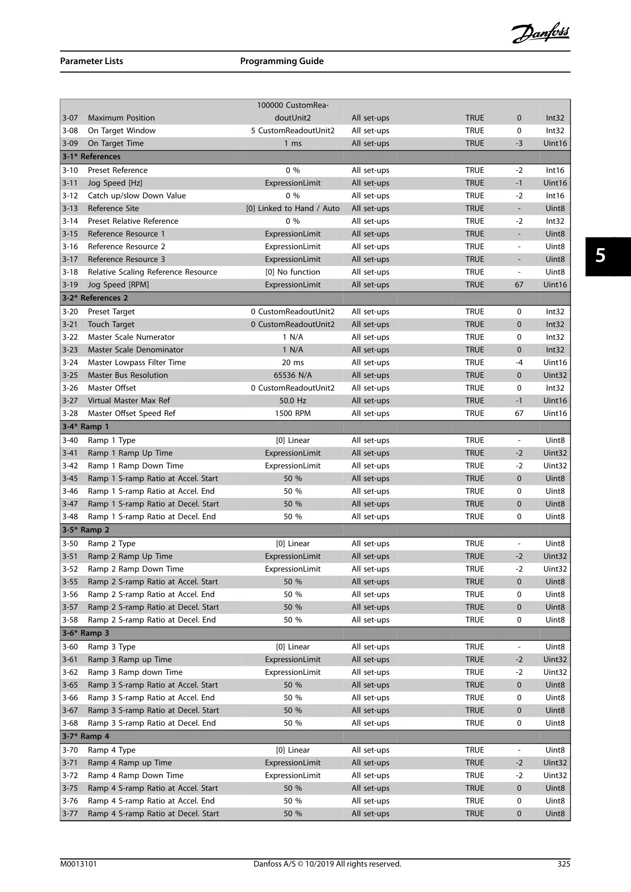
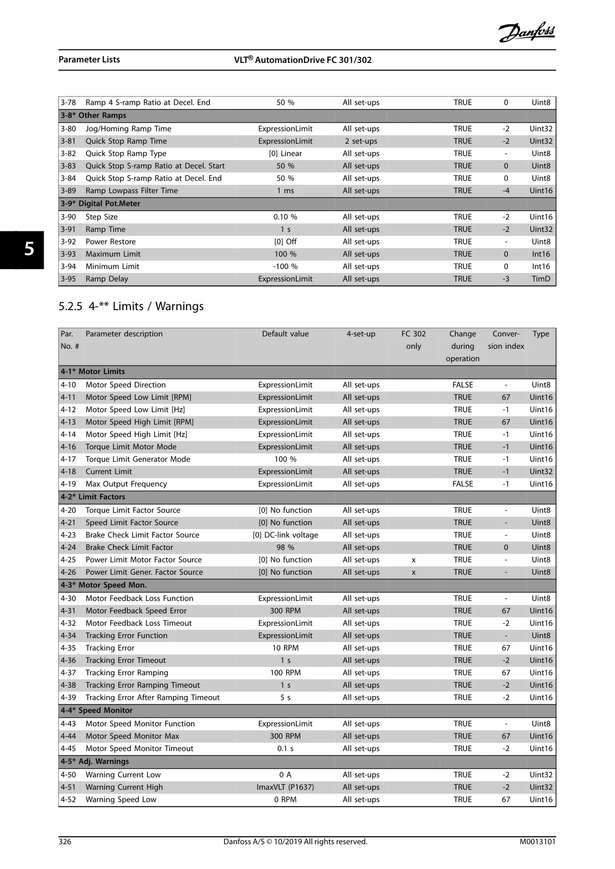
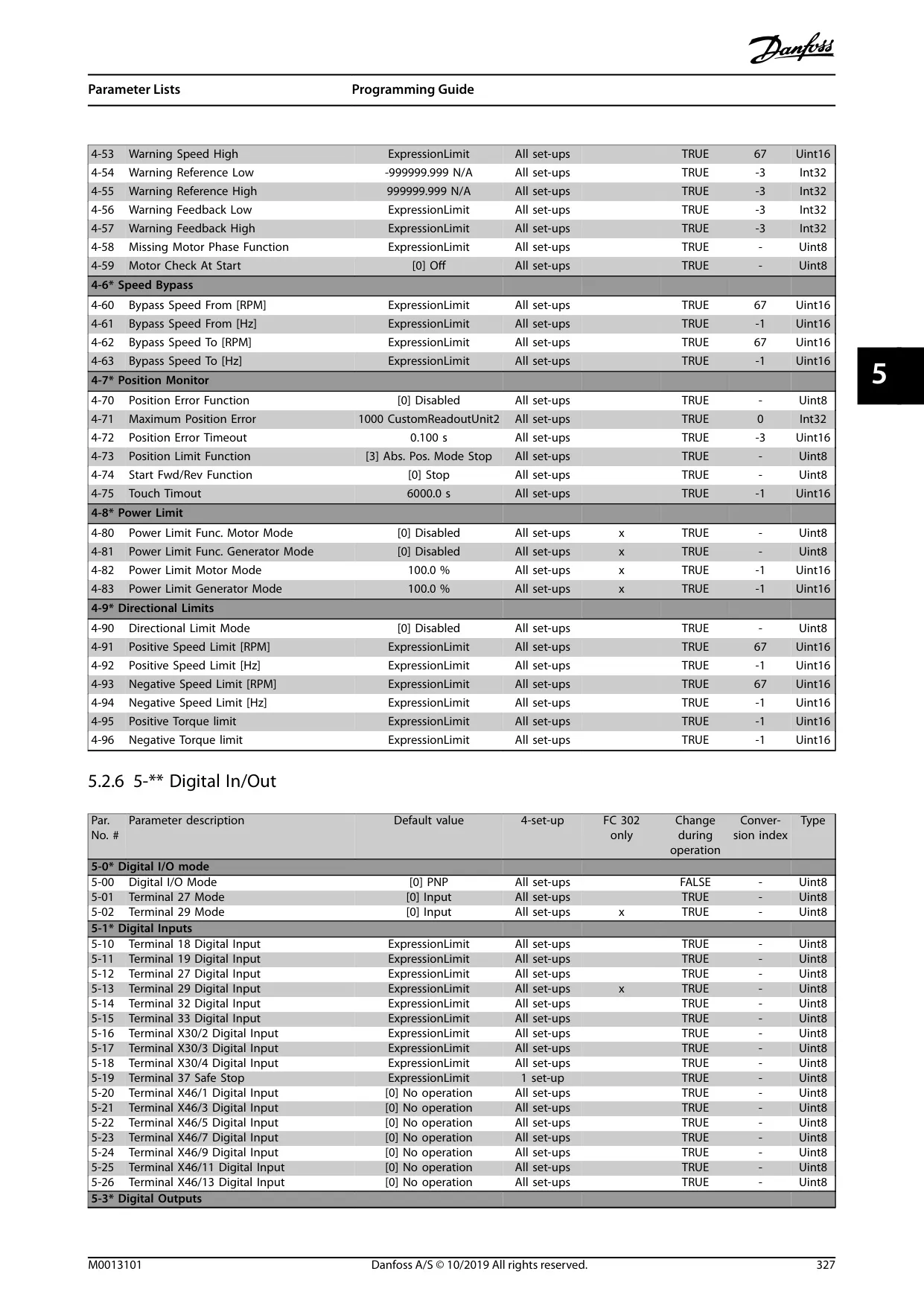
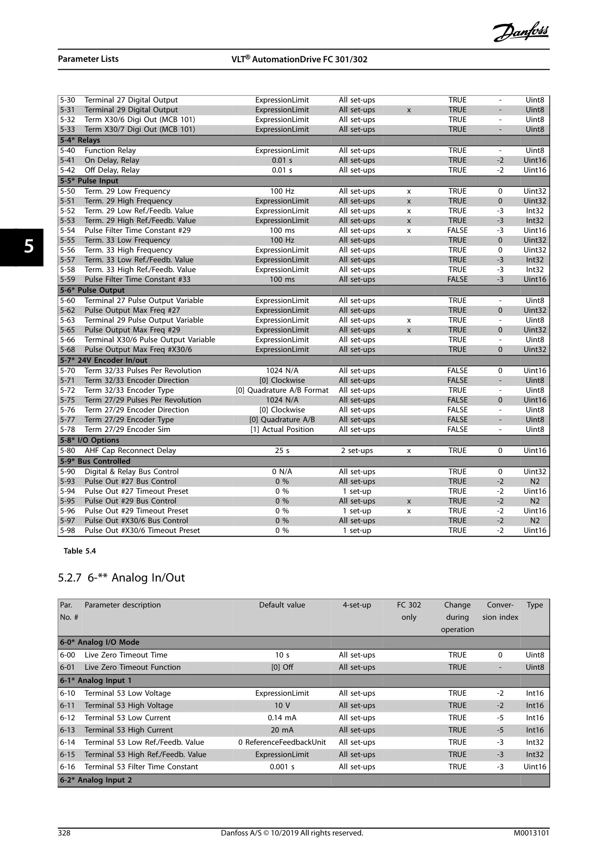
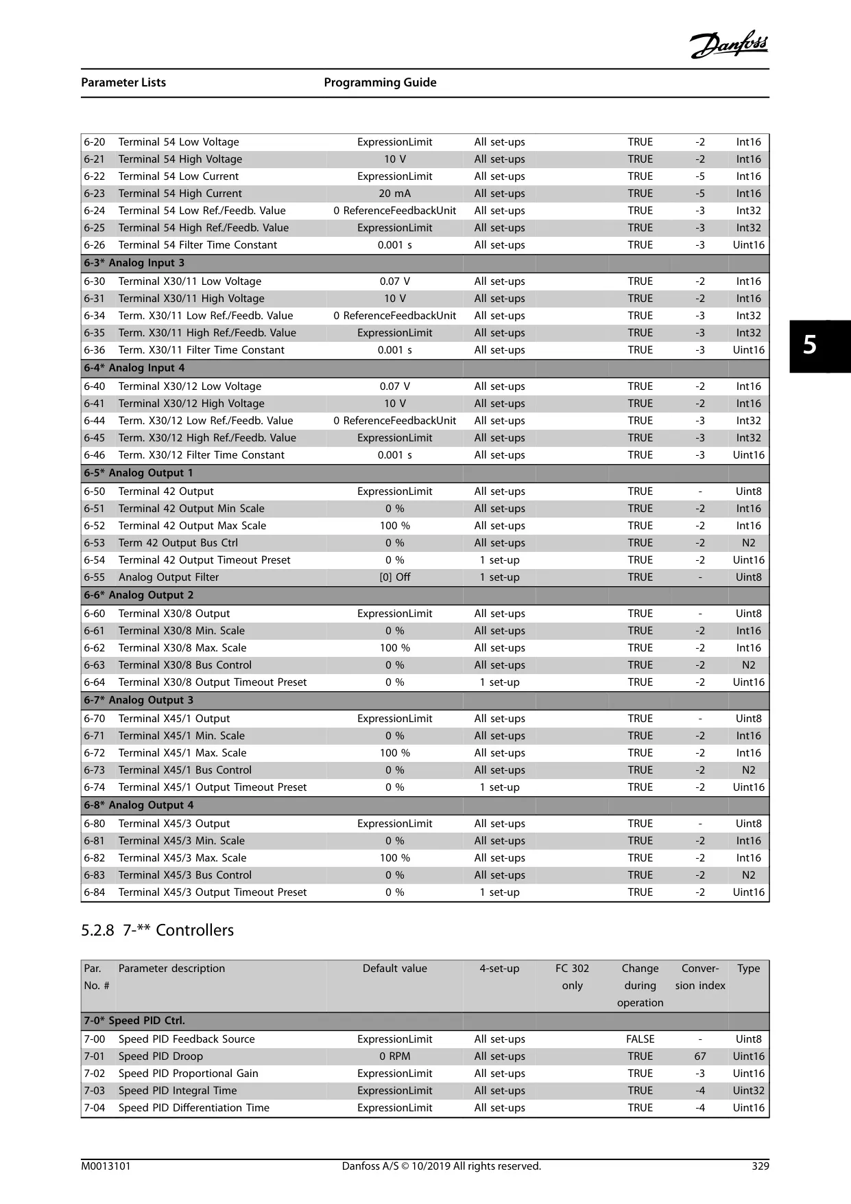
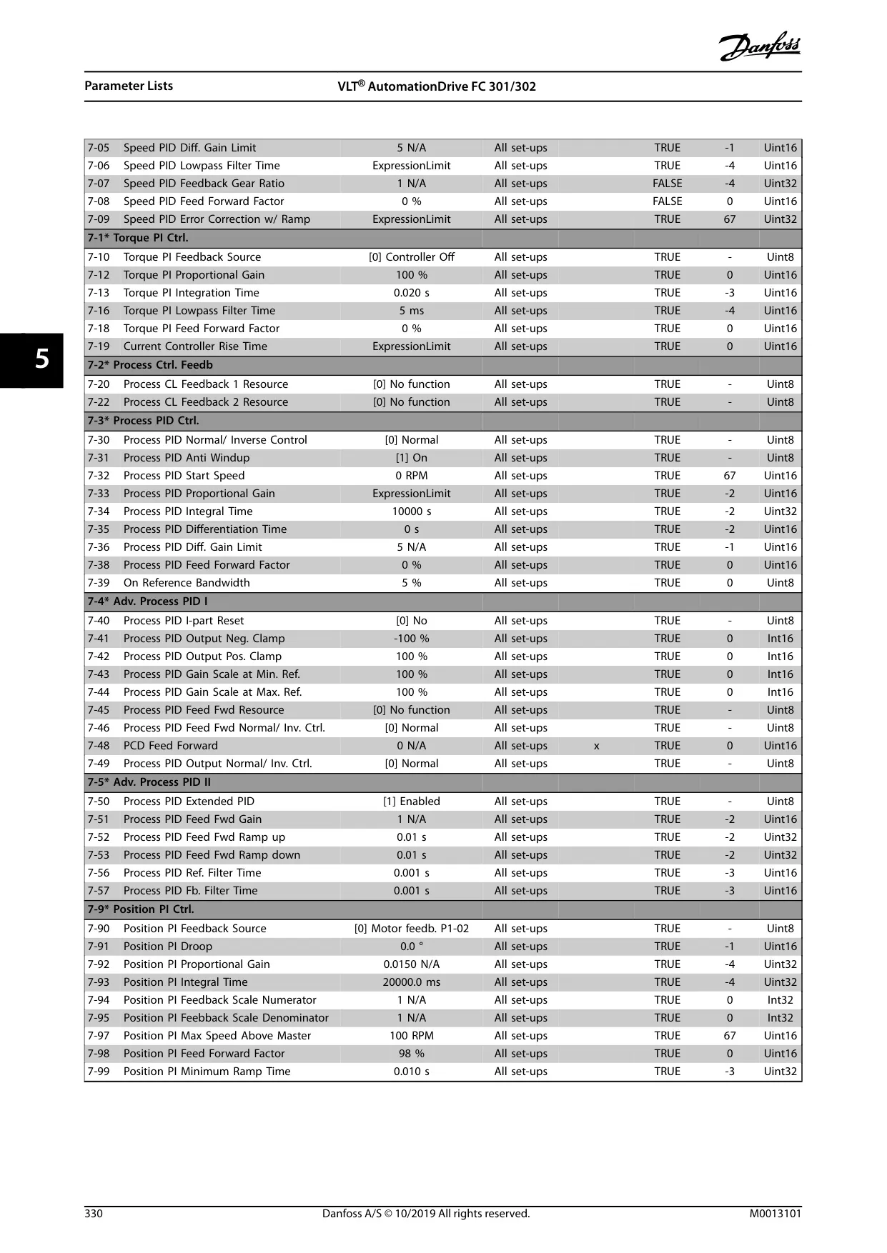
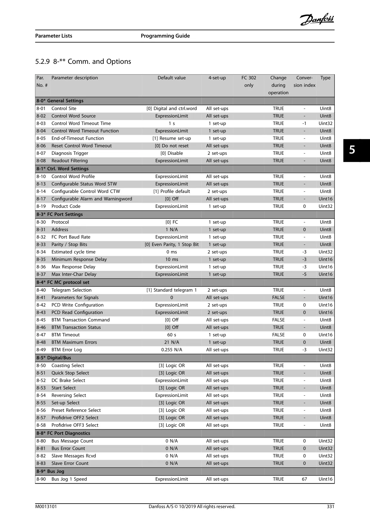
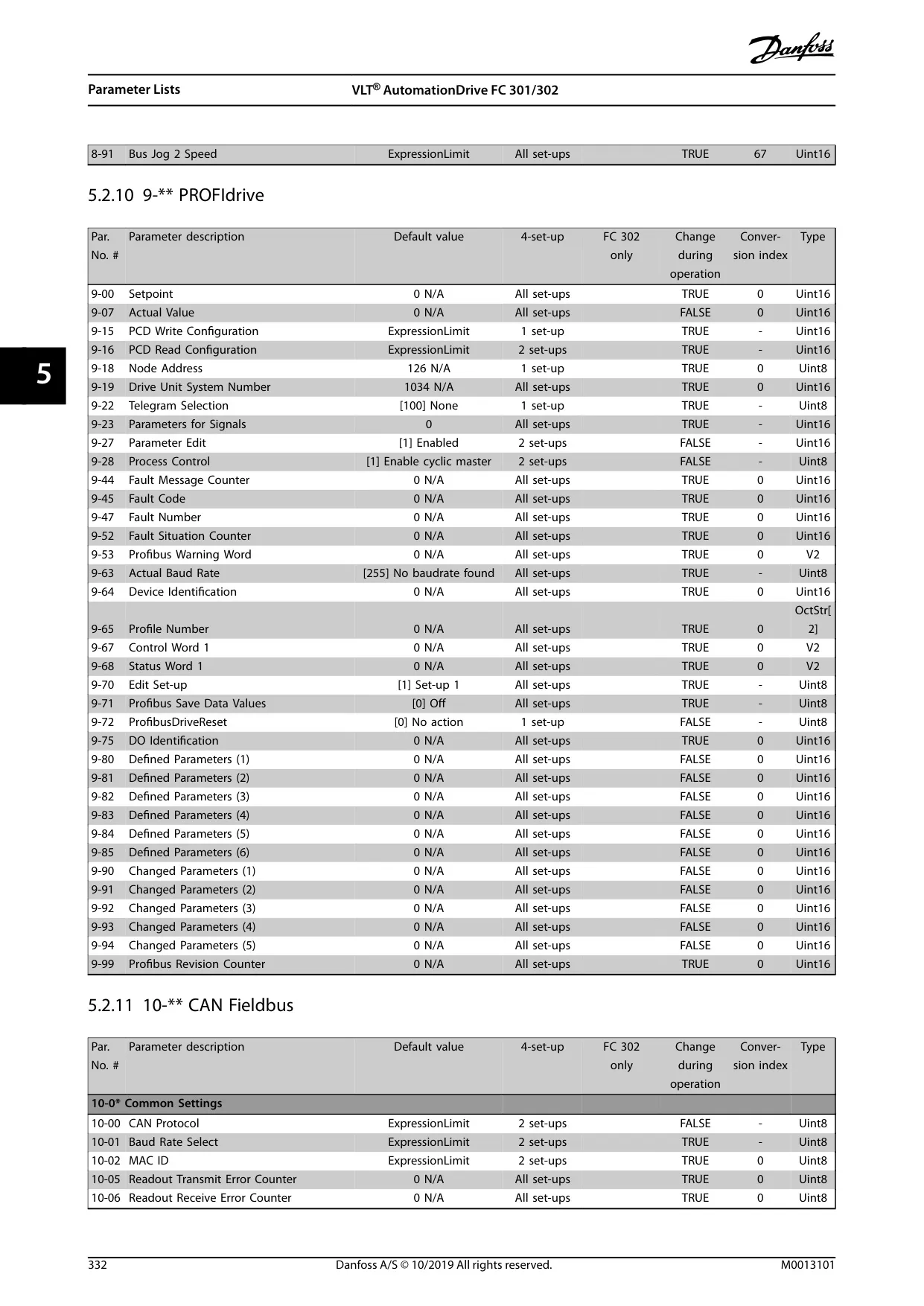
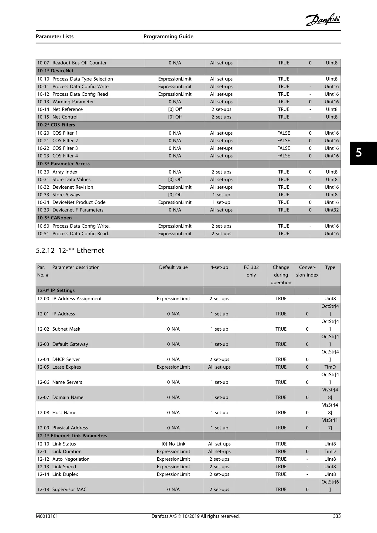
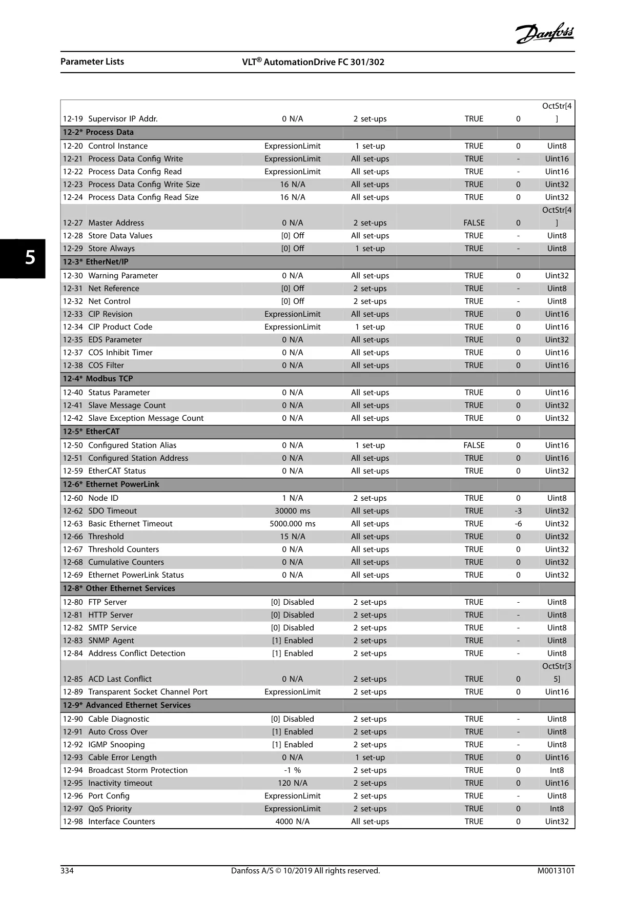
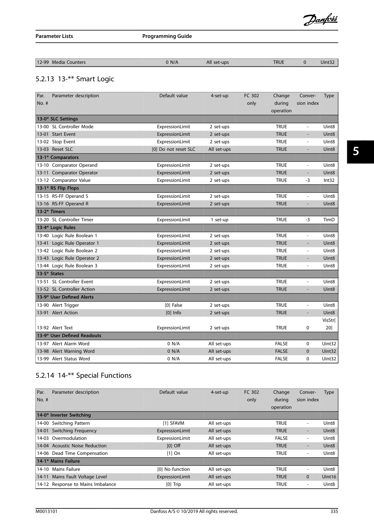
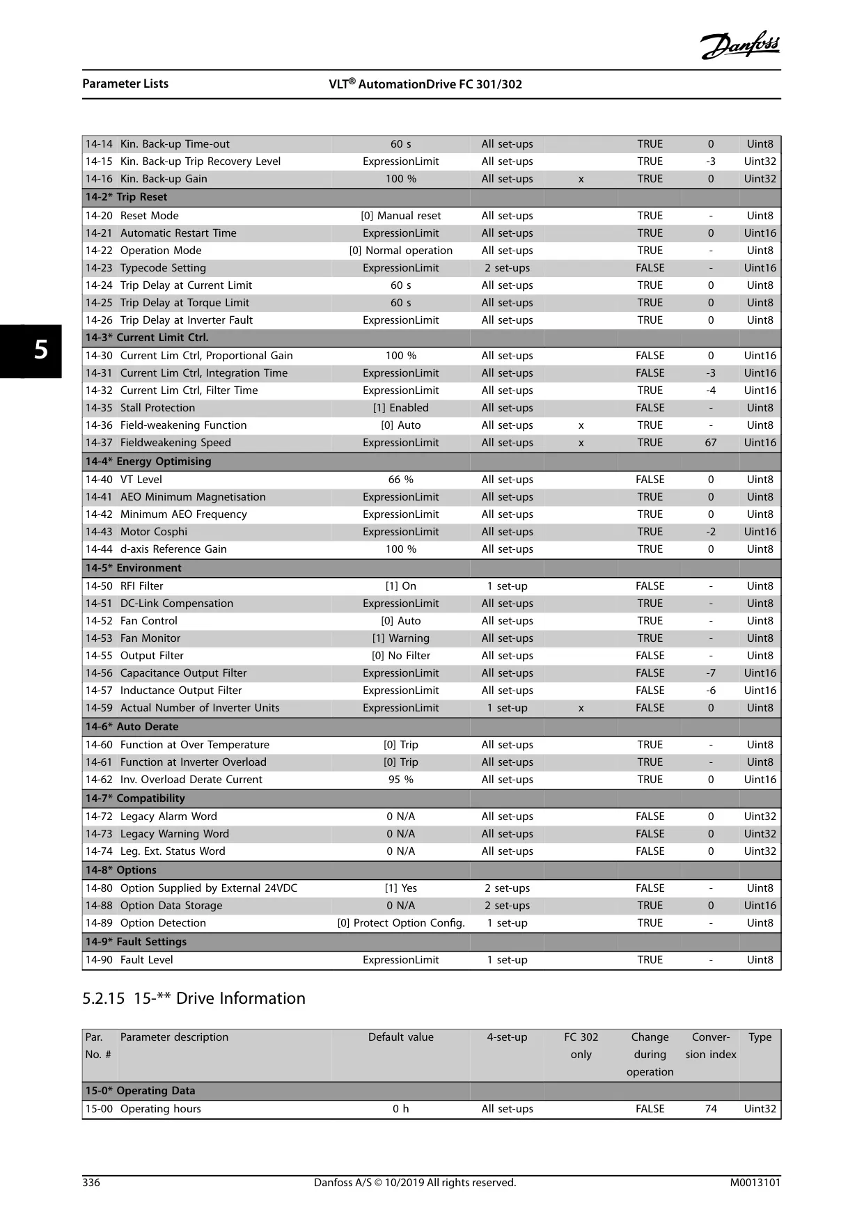
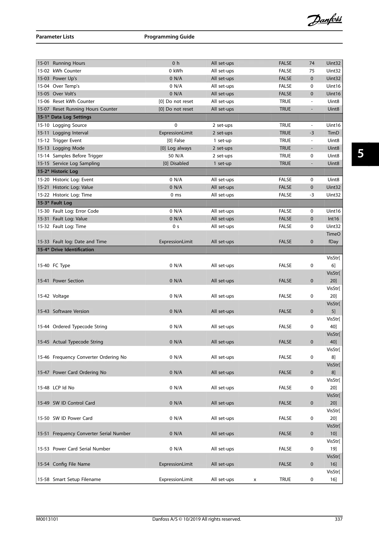
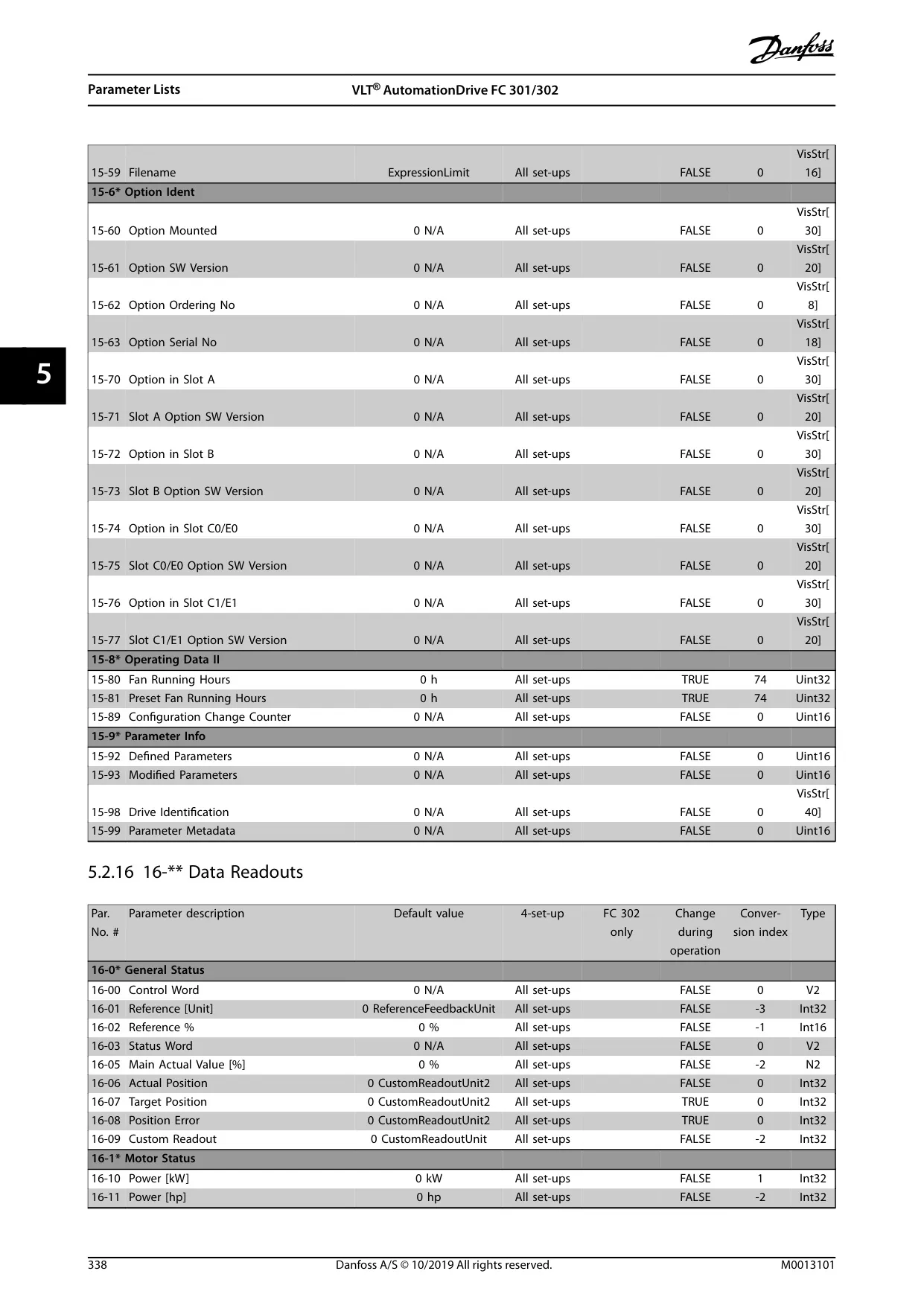
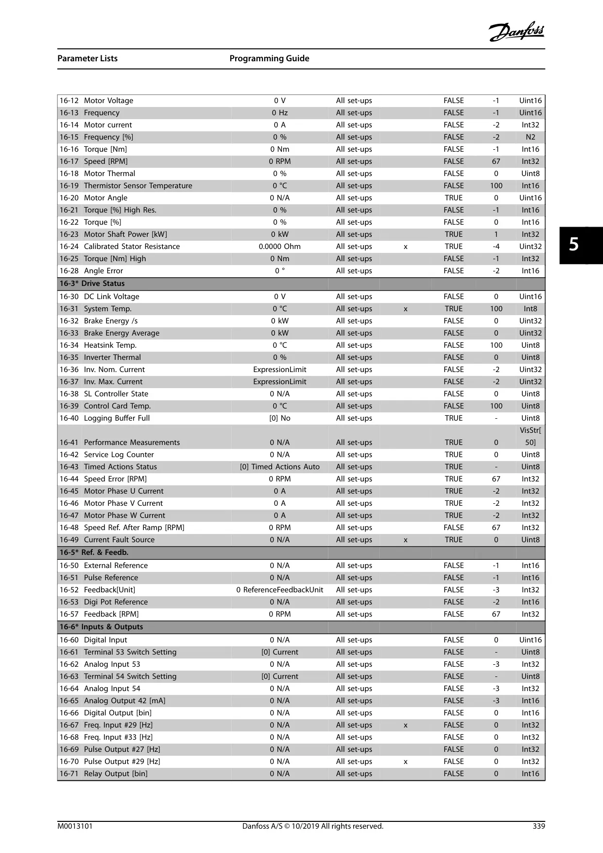
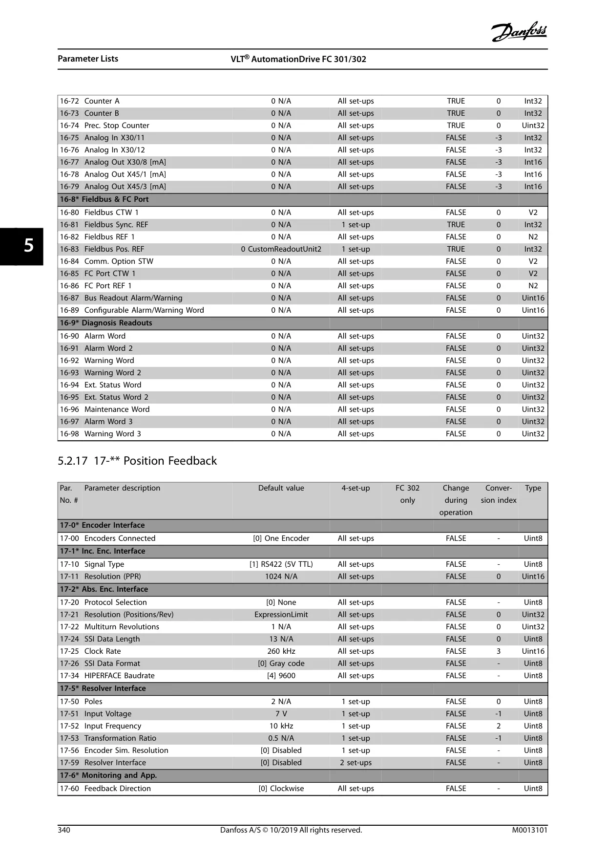
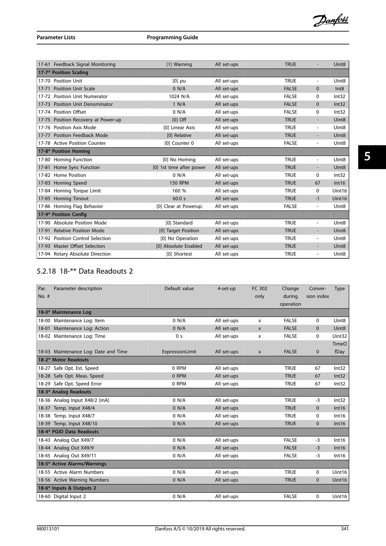
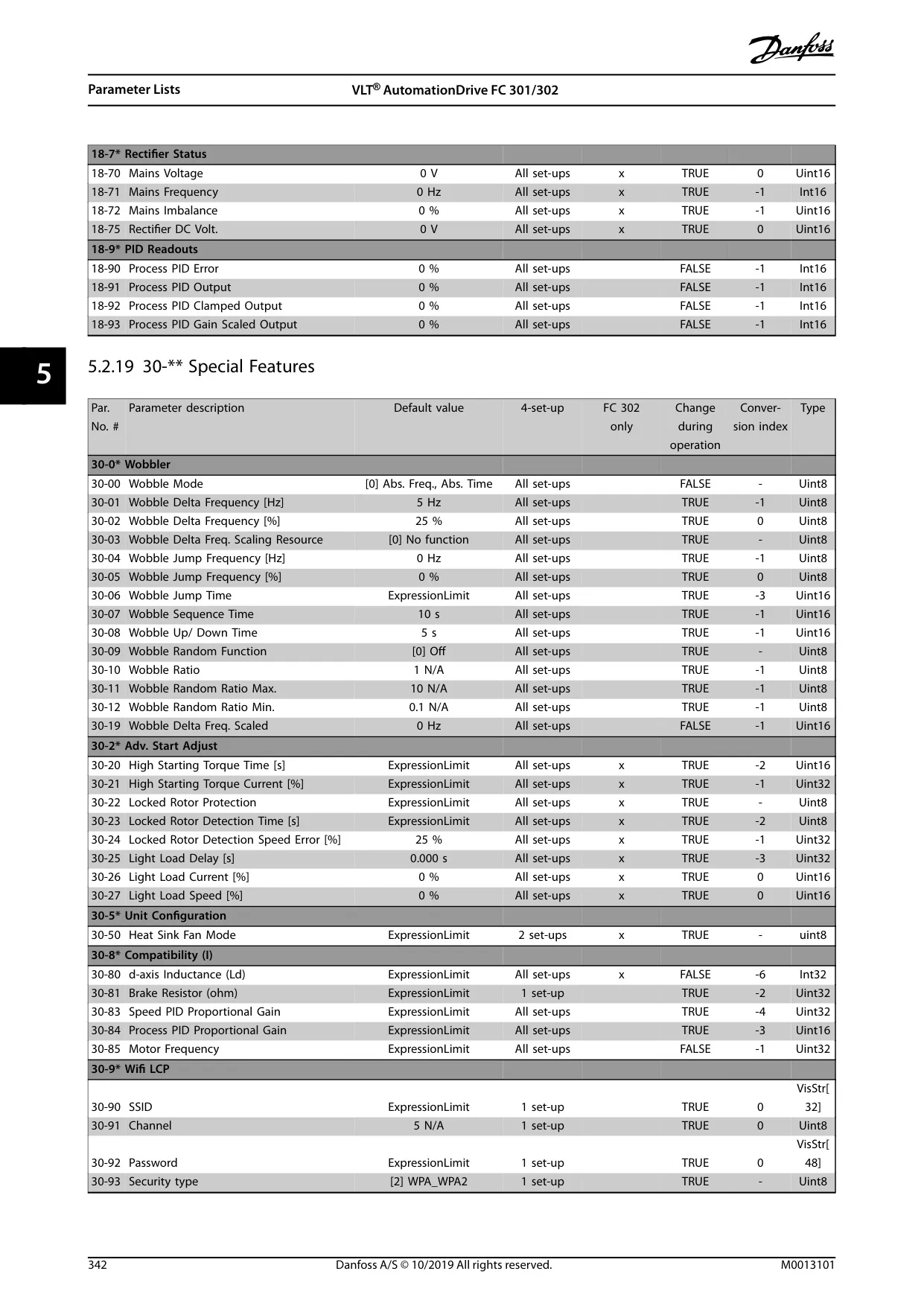
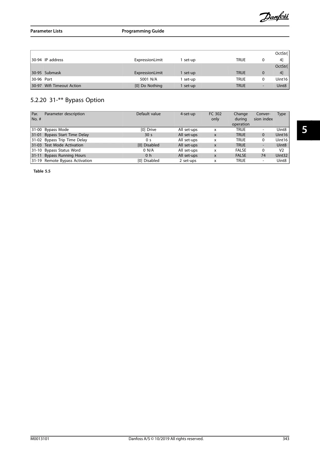
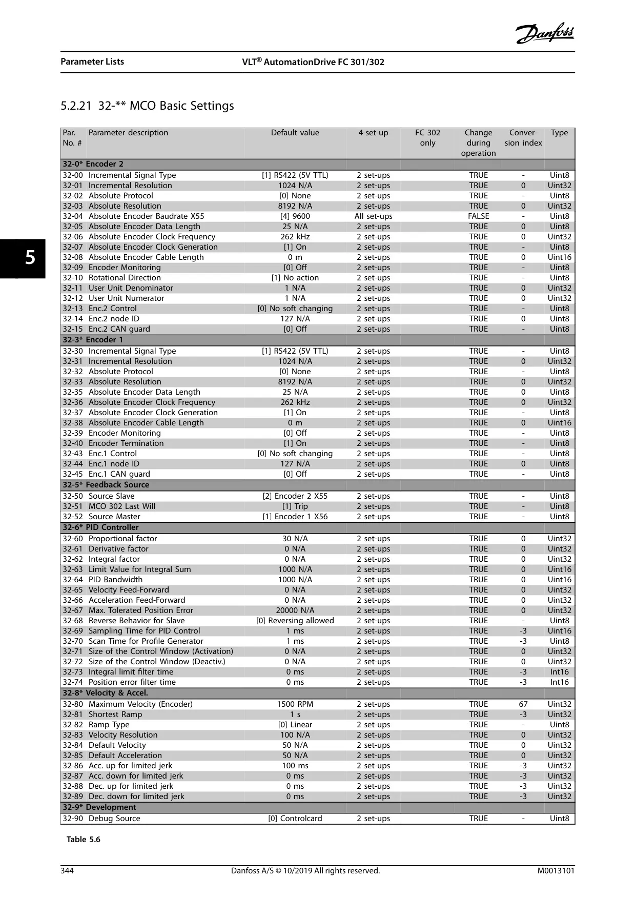
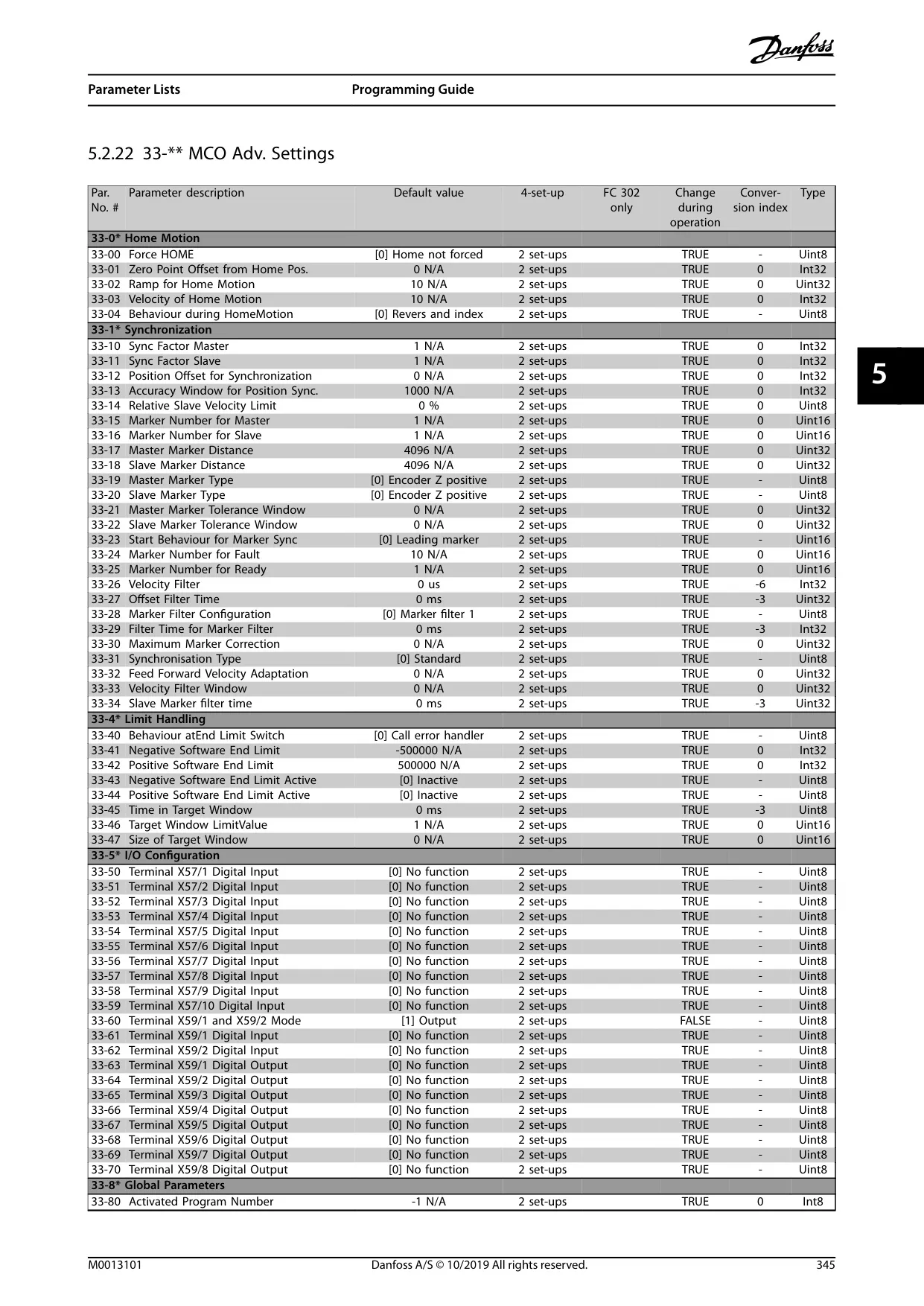
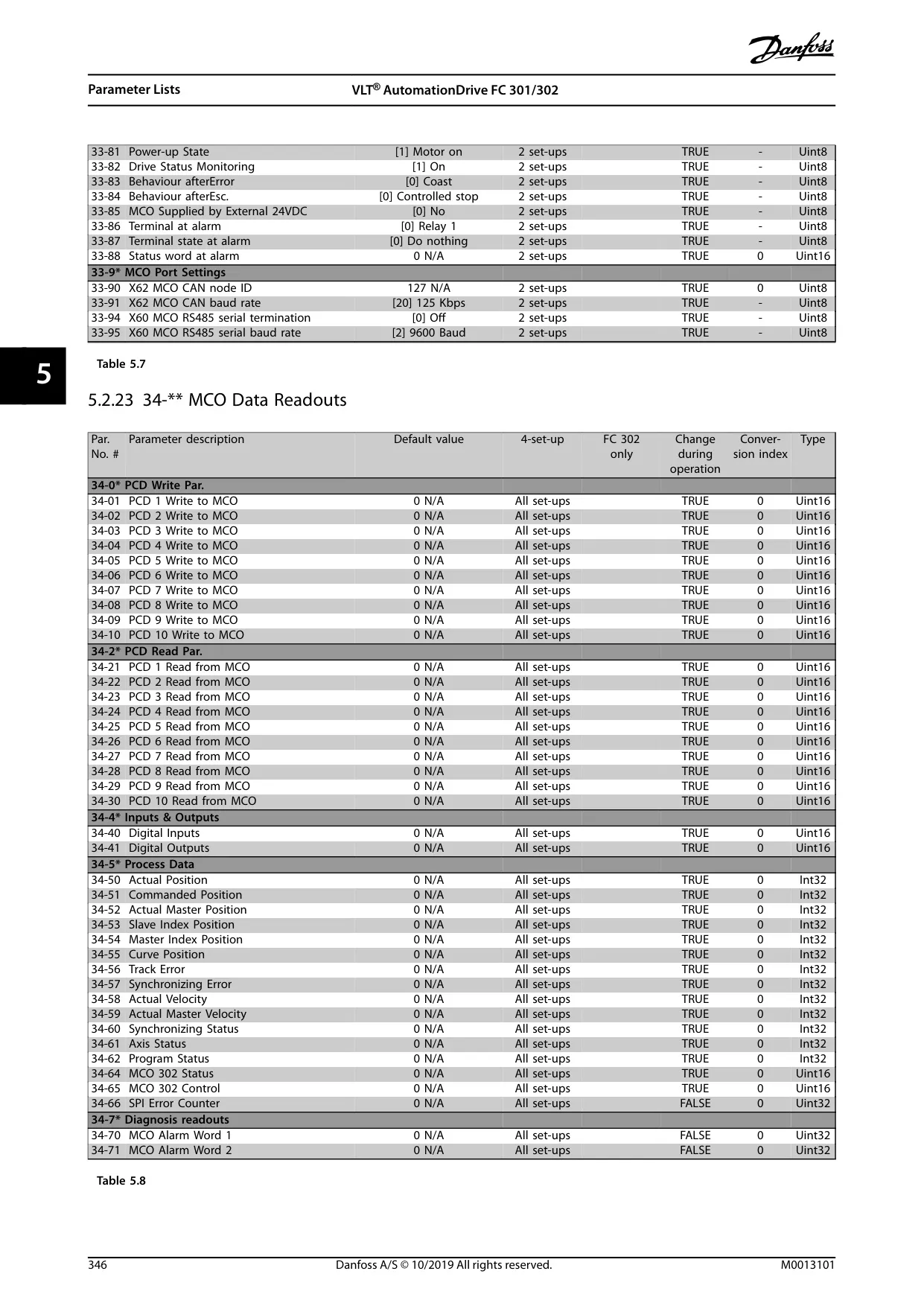
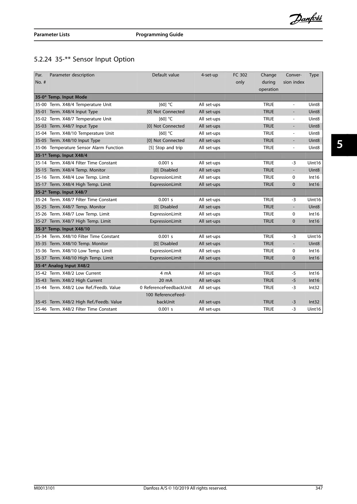
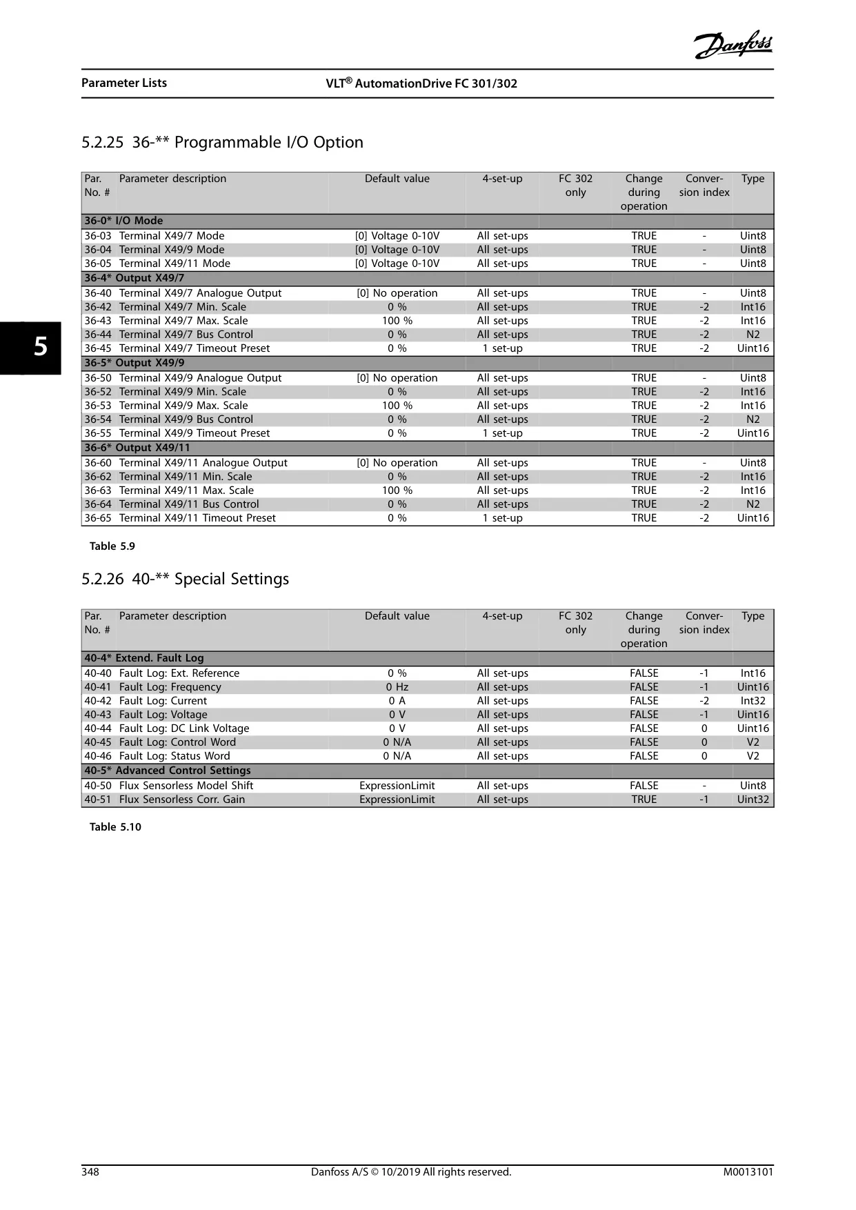
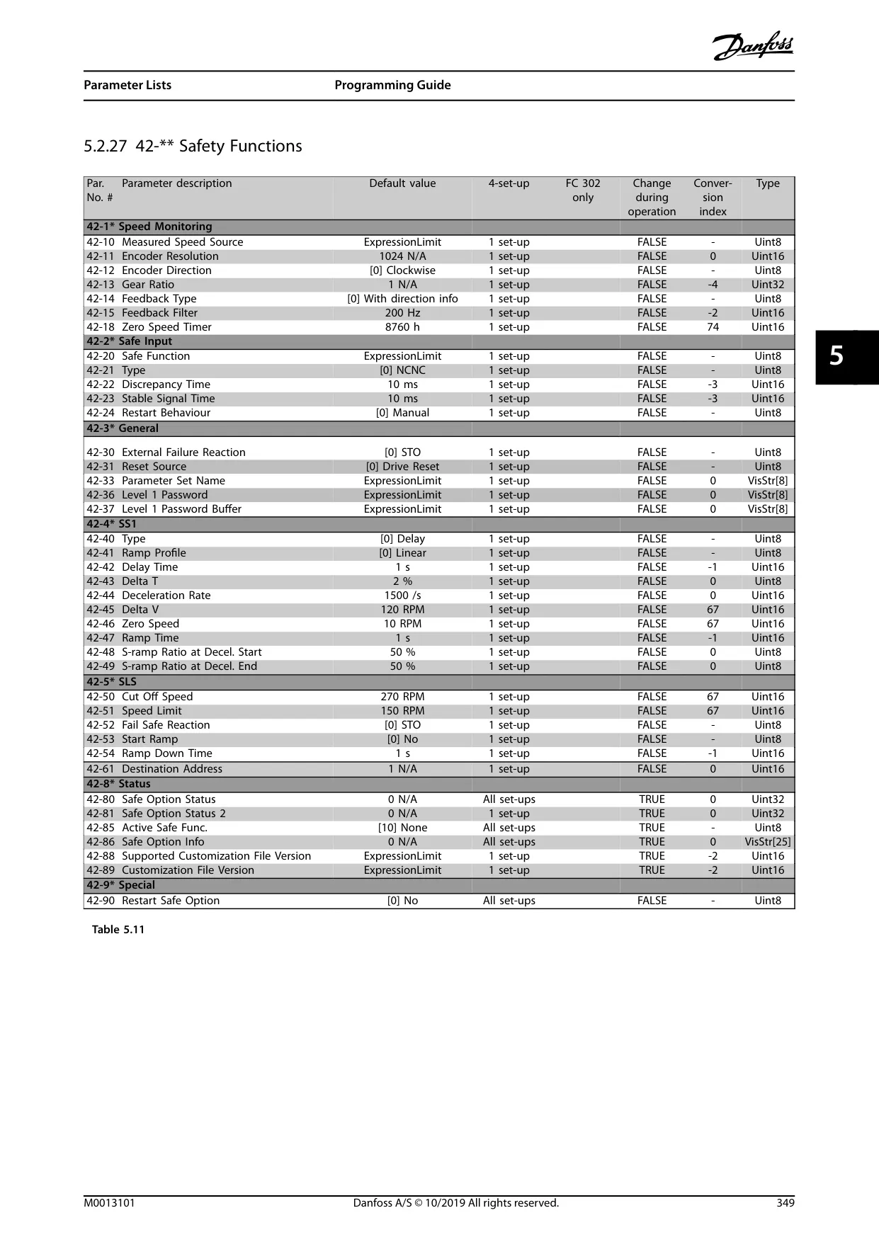
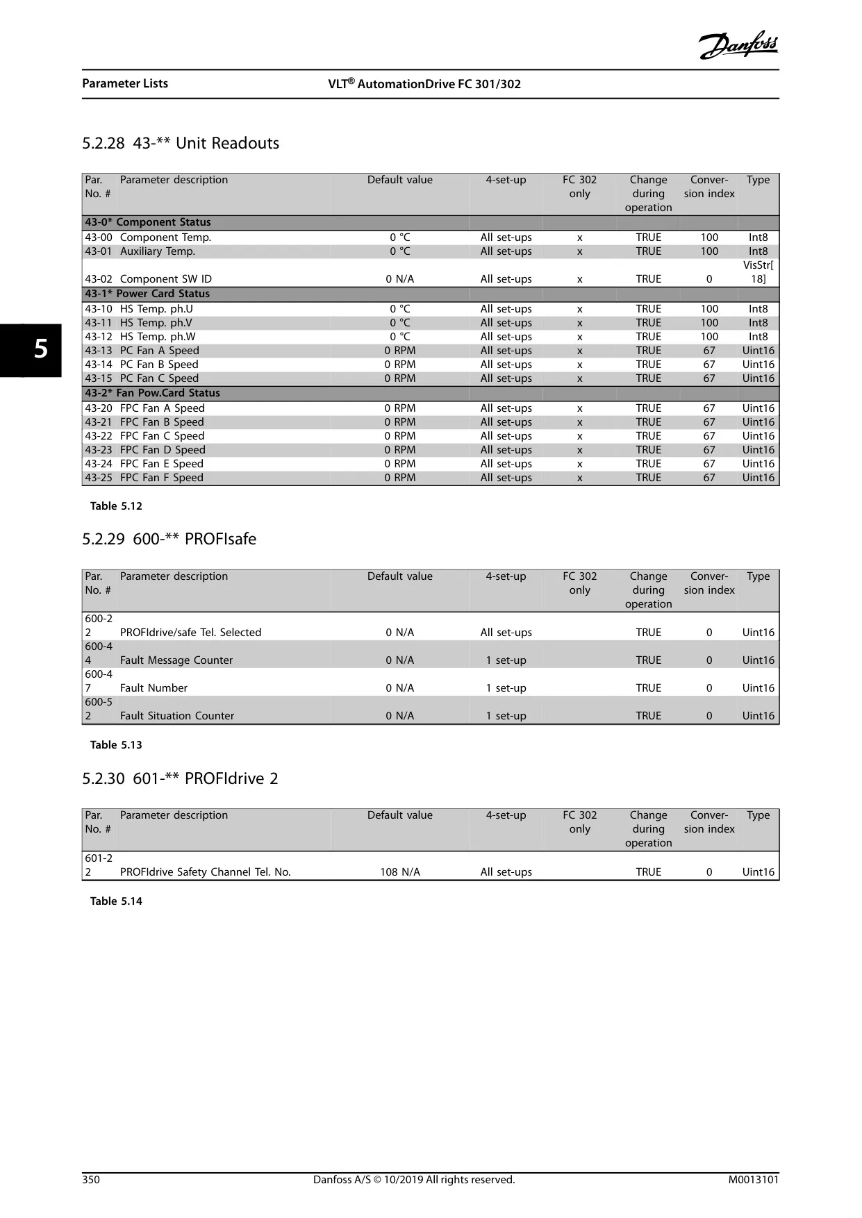
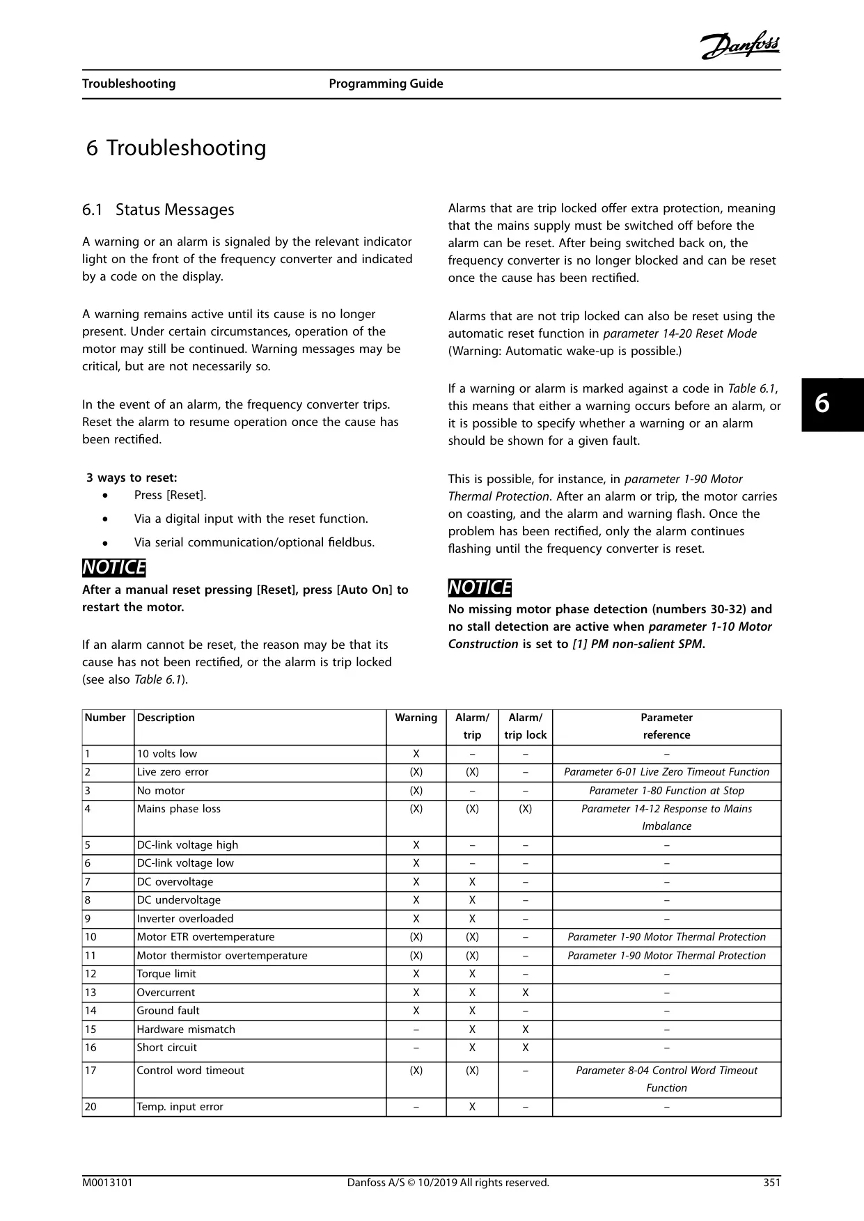
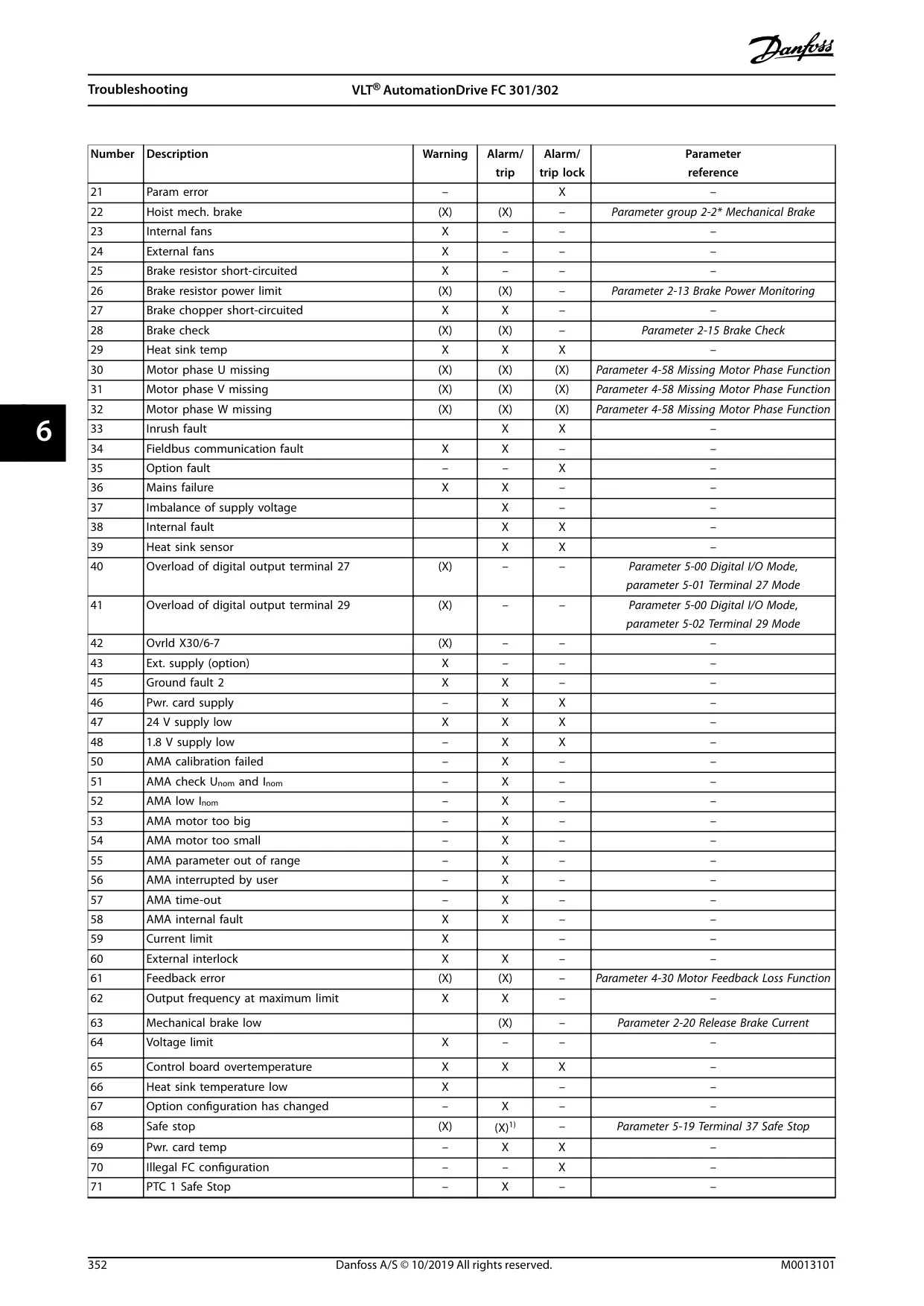
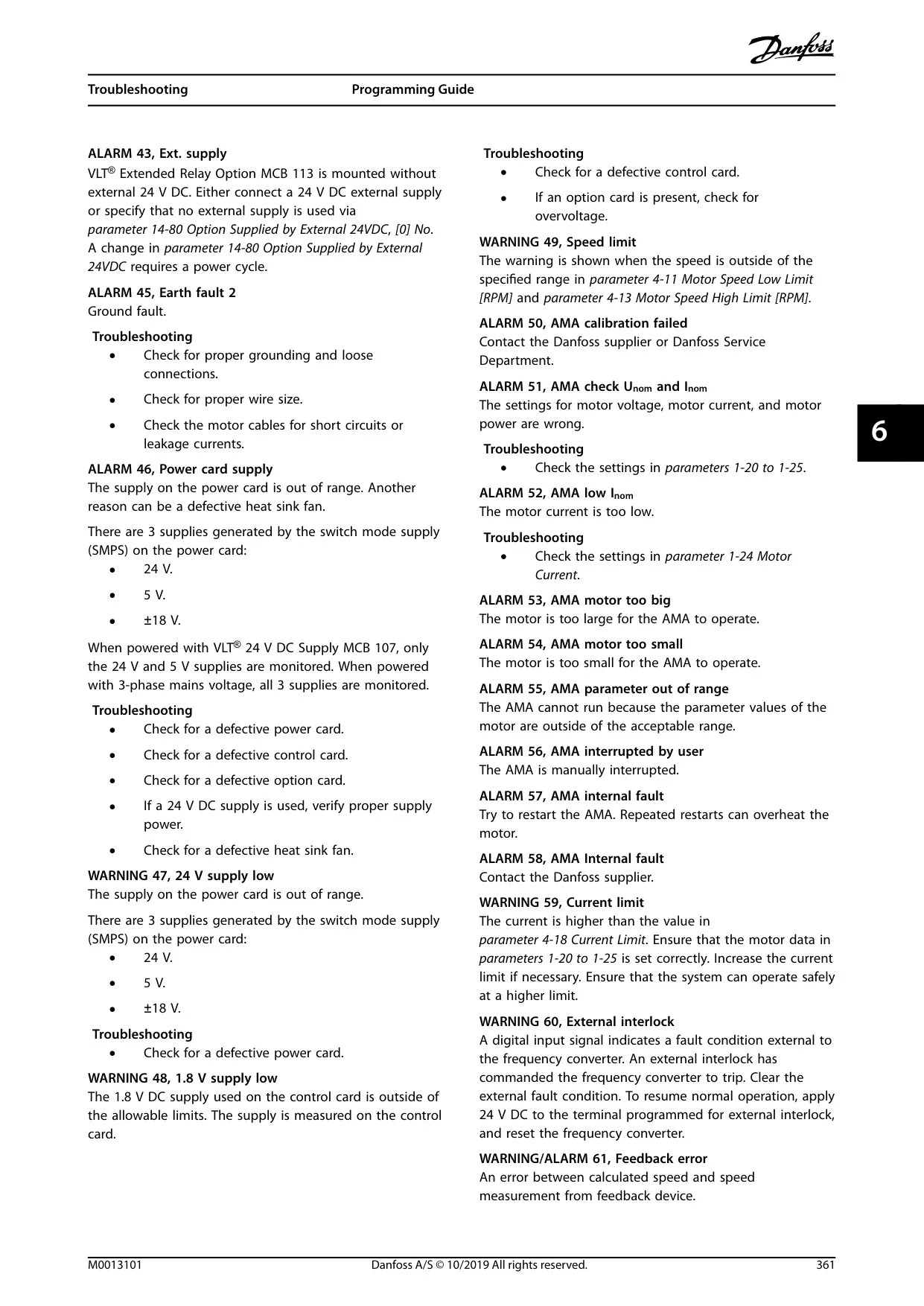
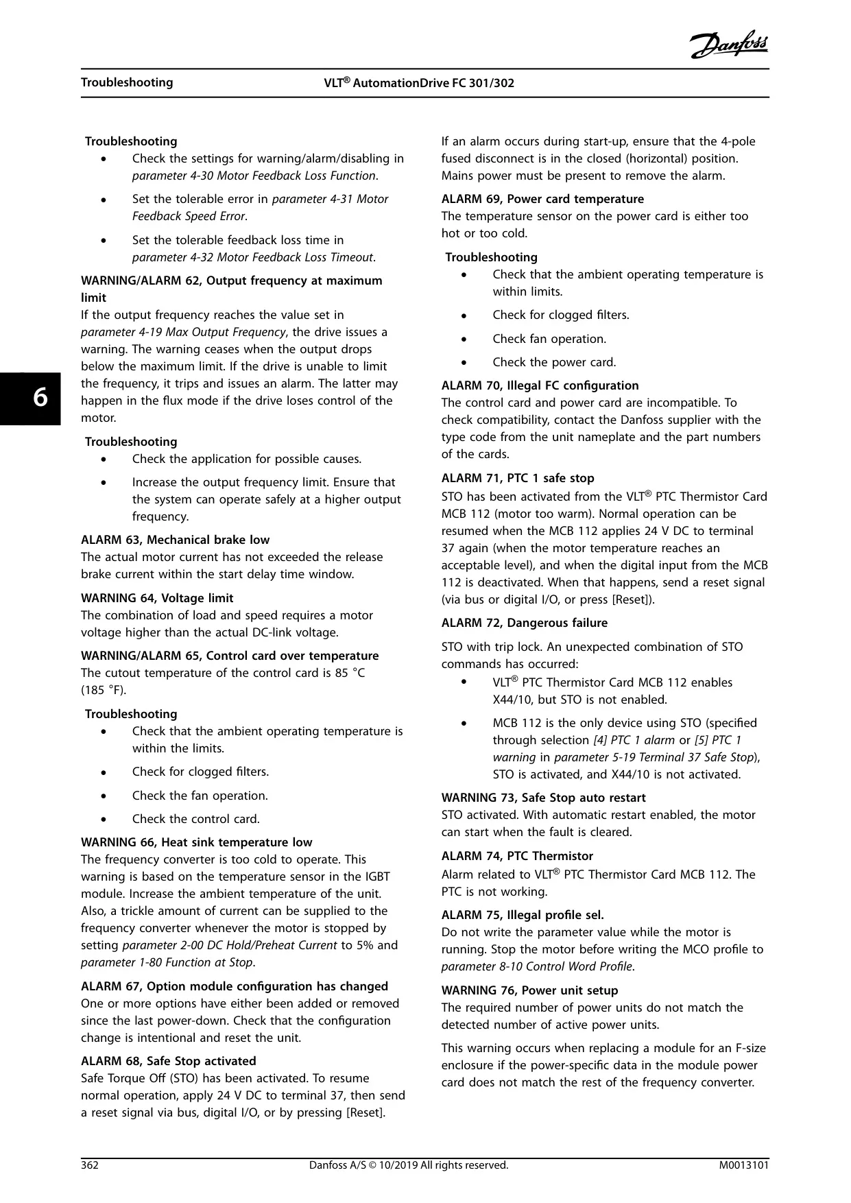
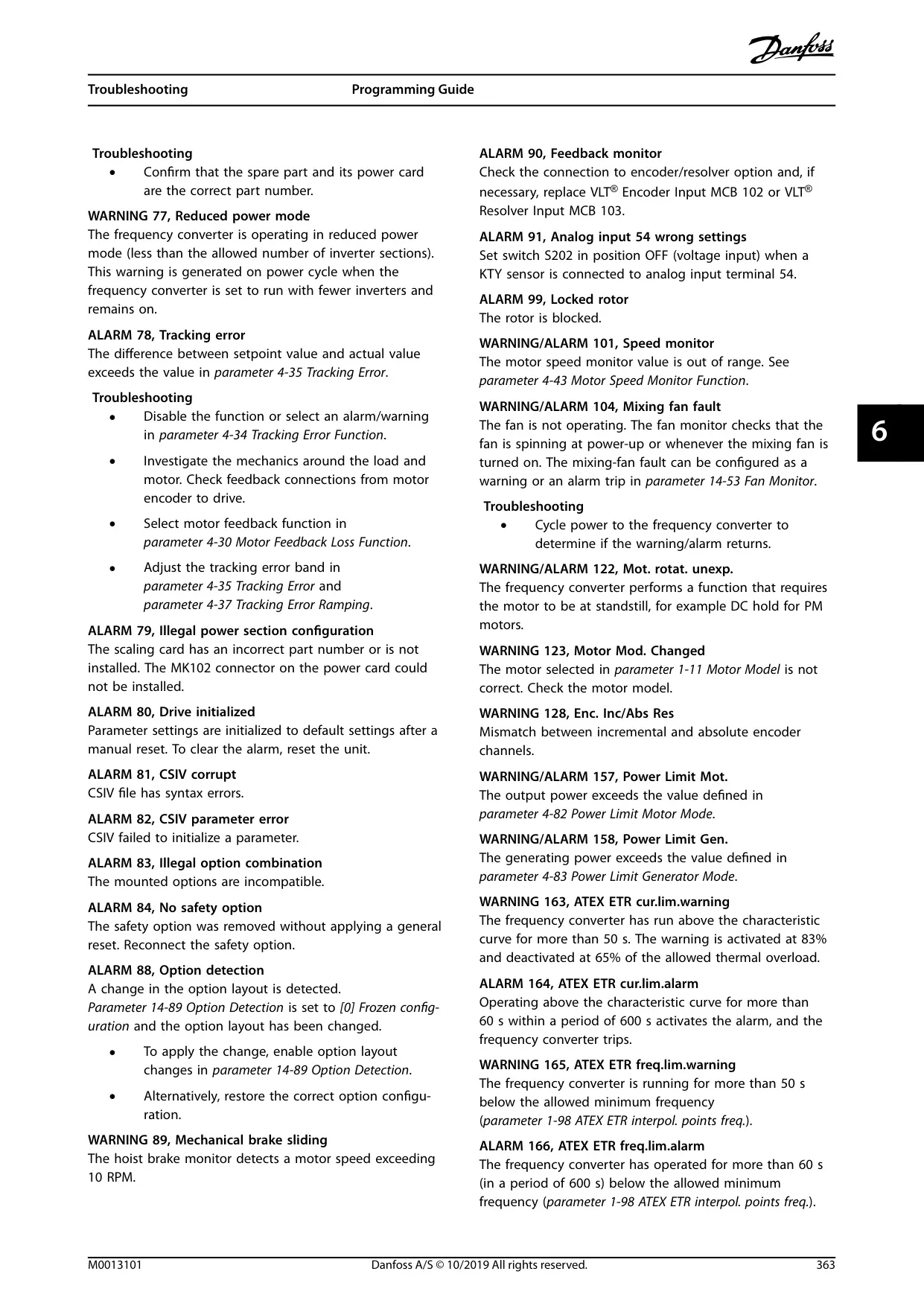
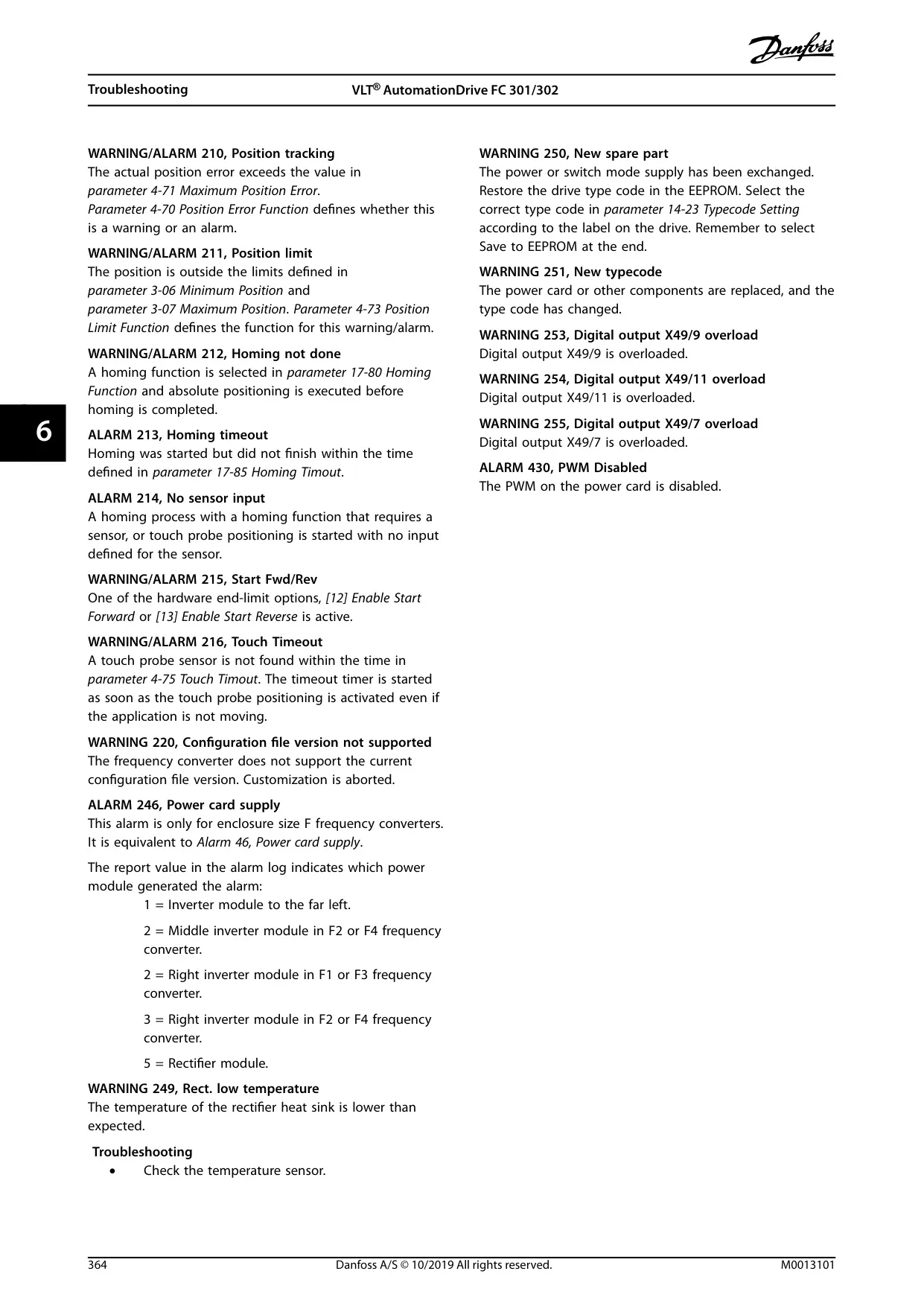

Danfoss FC-302 VFD Instructions
Here we offer the Danfoss FC-302 Variable Frequency Drive manual completely free and in English. We have cataloged this manual in the Variable Frequency Drives section on Manualverse, and it has been rated by 1 users with an average rating of 5. If you have any specific questions about Danfoss FC-302 Variable Frequency Drive, we suggest checking the Frequently Asked Questions (FAQs) section of this manual.
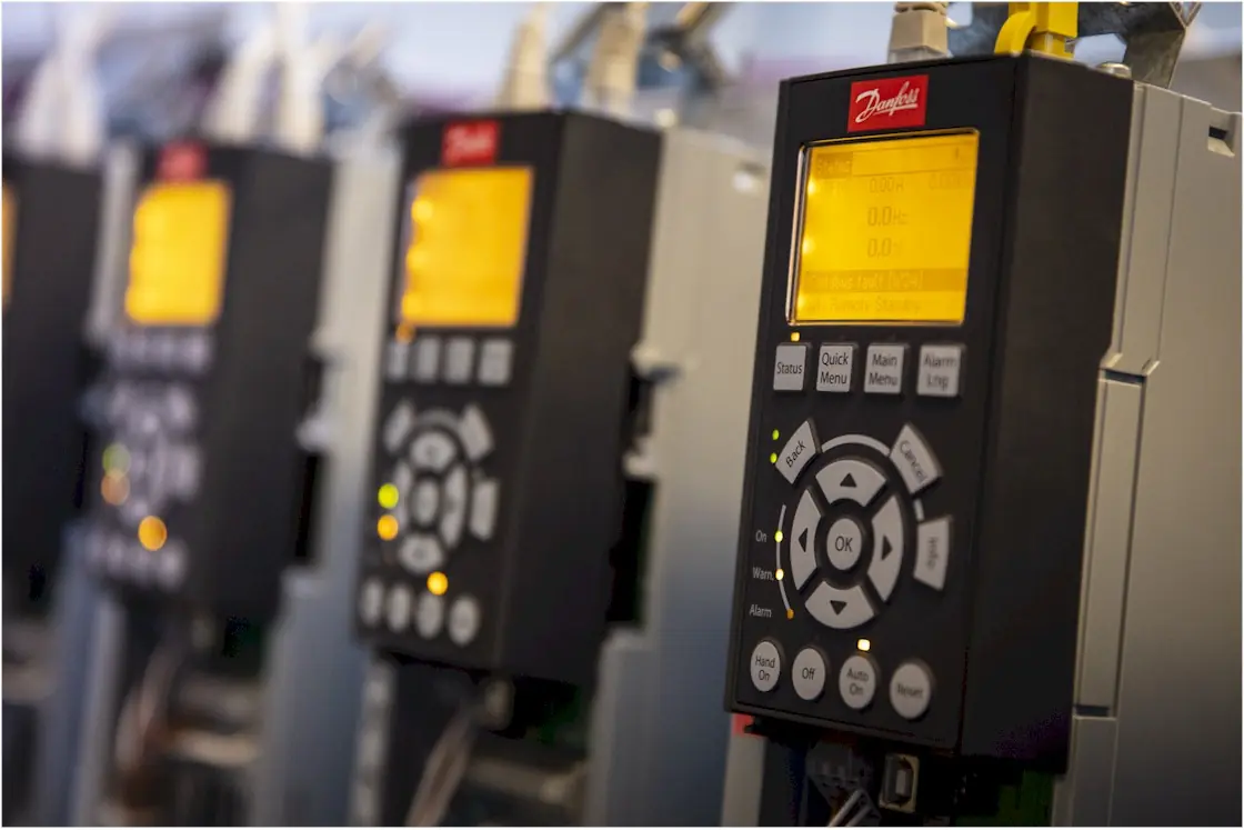
Product Images
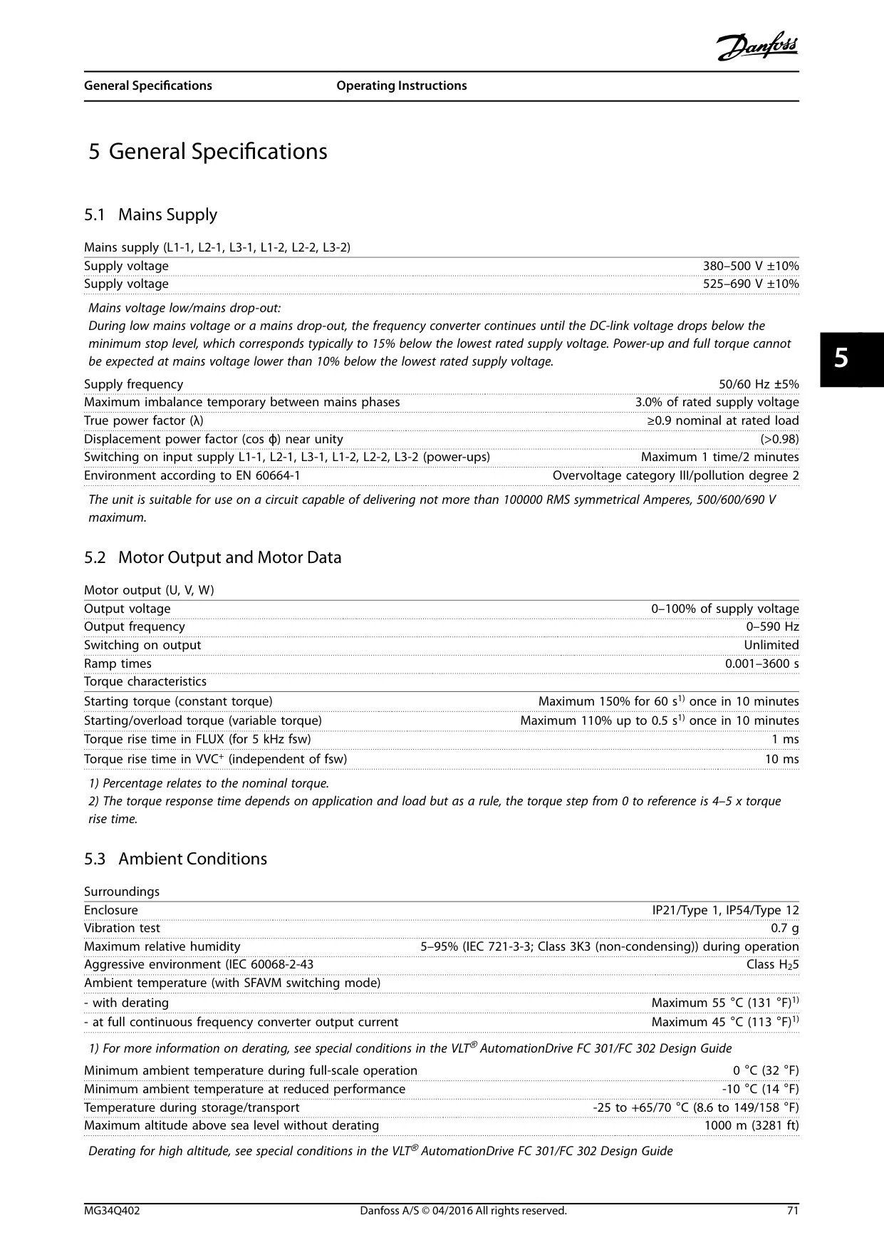
Danfoss FC-302 Variable Frequency Drive Specifications
| Specification | Value | Notes |
|---|---|---|
| Product Line | VLT® AutomationDrive FC 302 | 12-pulse variant |
| Supply Voltage Range | 380–500 V ±10% 525–690 V ±10% |
Multi-voltage support |
| Supply Frequency | 50/60 Hz ±5% | Standard grid frequencies |
| Output Voltage Range | 0–100% of supply voltage | Variable output voltage |
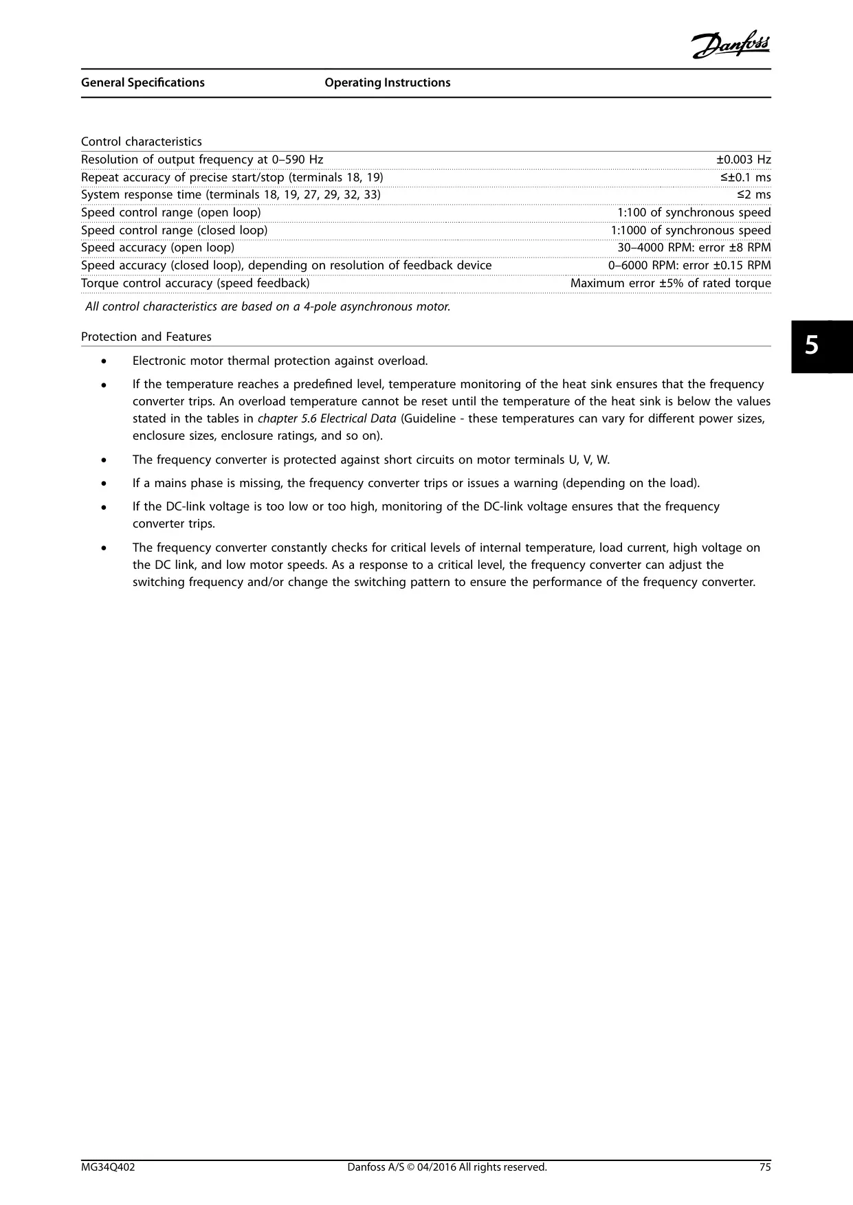
| Output Frequency Range | 0–590 Hz | Limited to 590 Hz from SW version 6.72 onwards (export control) |
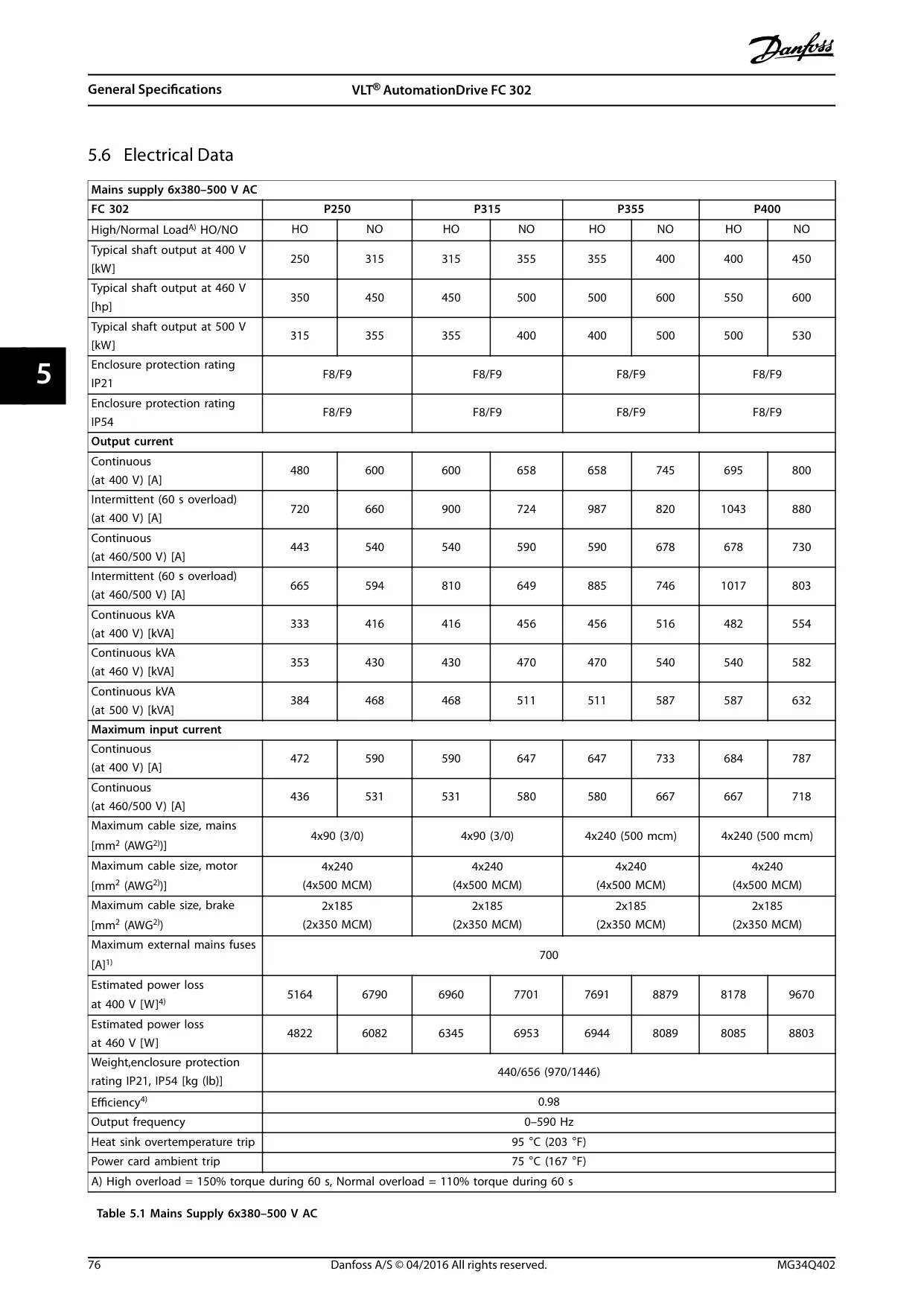
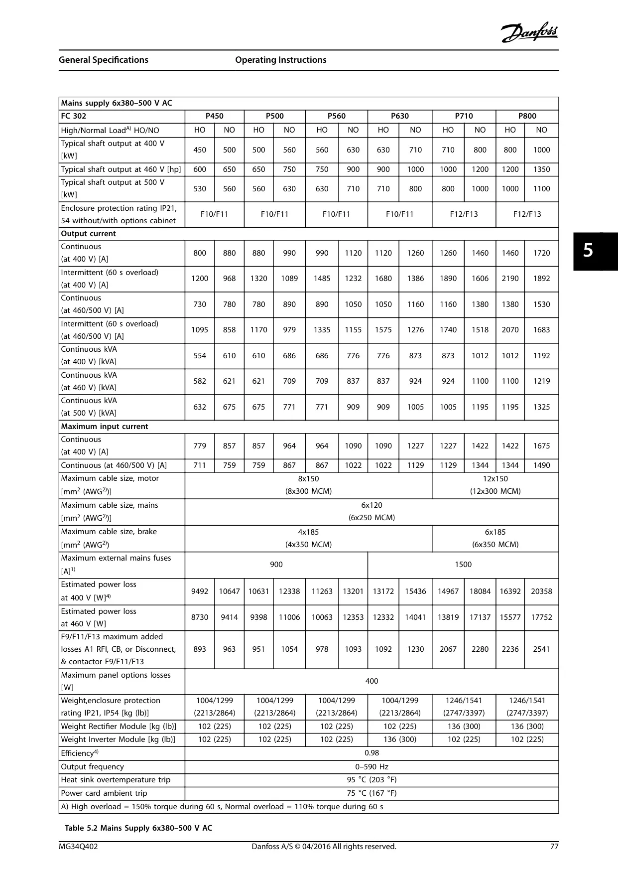
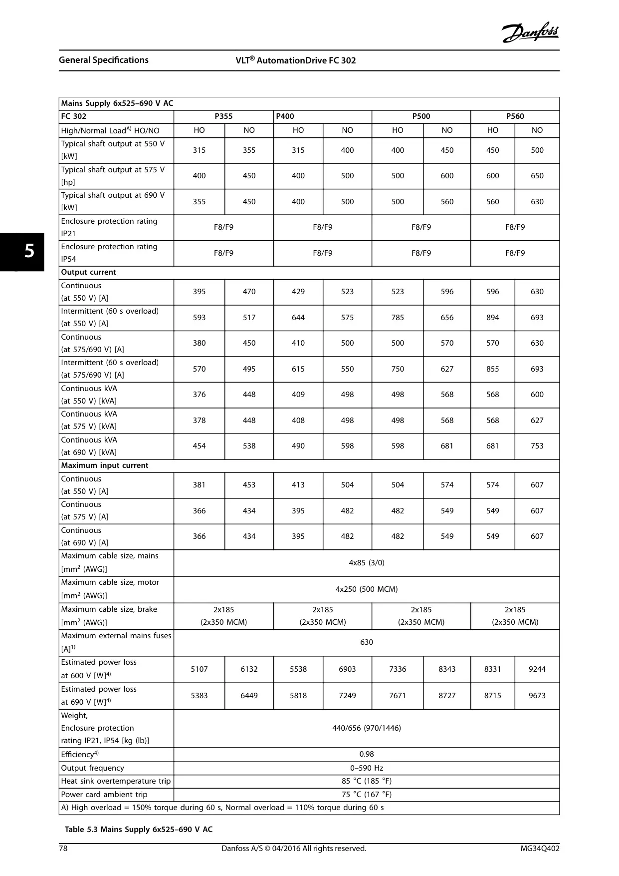
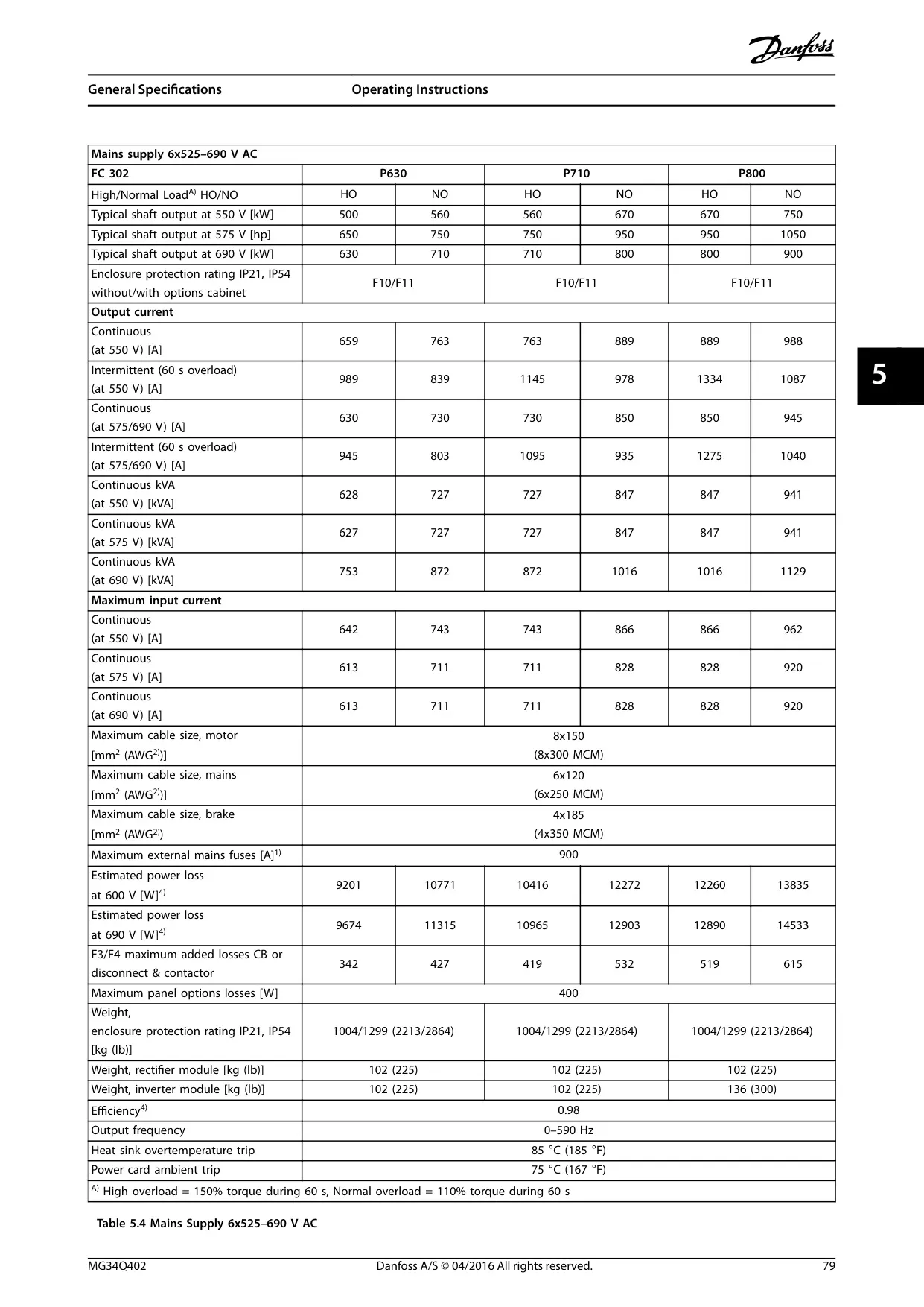
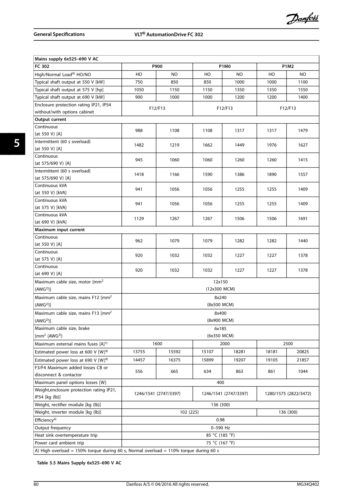
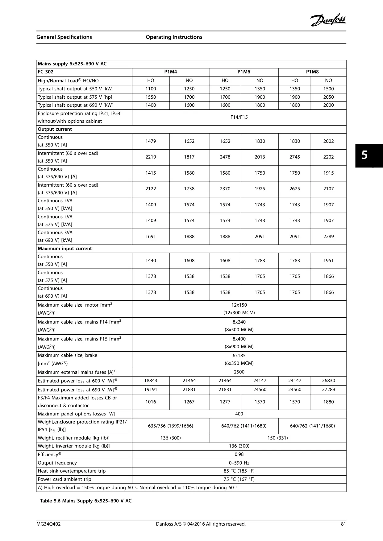
| Continuous Output Current (HO/NO) | 380-500V: 443 A (P250T5) to 1720 A (P1000T5) 525-690V: 380 A (P355T7) to 2002 A (P1M8T7) |
Refer to power size and overload mode (High Overload/Normal Overload) |
| Starting Torque (Constant Torque) | Maximum 150% for 60 s (once in 10 minutes) | For high overload applications |
| Starting/Overload Torque (Variable Torque) | Maximum 110% up to 0.5 s (once in 10 minutes) | For normal overload applications |
| Enclosure Protection Rating | IP21/Type 1, IP54/Type 12 | Environmental protection ratings |
| Ambient Operating Temperature | 0°C (32°F) to 45°C (113°F) at full continuous output Up to 55°C (131°F) with derating |
Operation with SFAVM switching mode |
| Storage/Transport Temperature | -25 to +65/70°C (8.6 to 149/158°F) | Wide temperature tolerance |
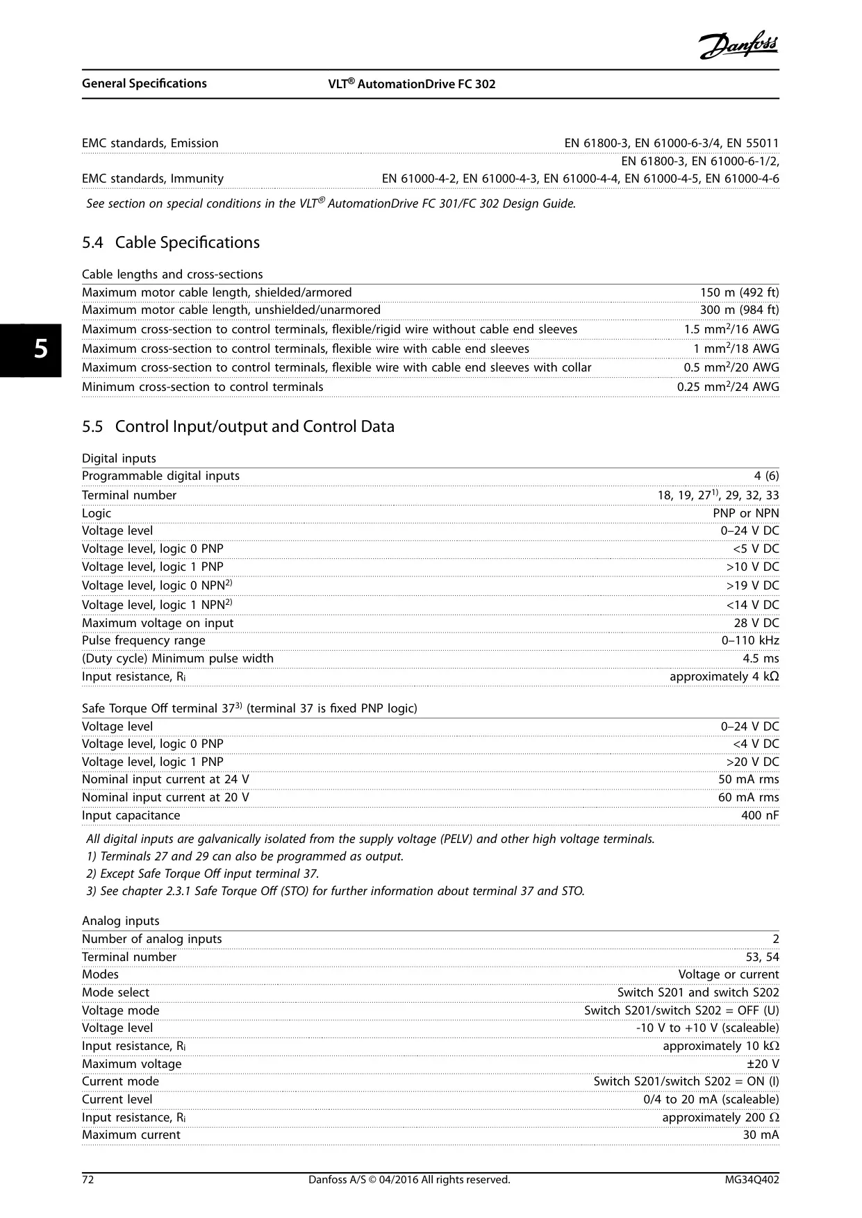
| Maximum Motor Cable Length (Shielded) | 150 m (492 ft) | For optimal EMC performance |
| Maximum Motor Cable Length (Unshielded) | 300 m (984 ft) | May not comply with EMC emission specifications |
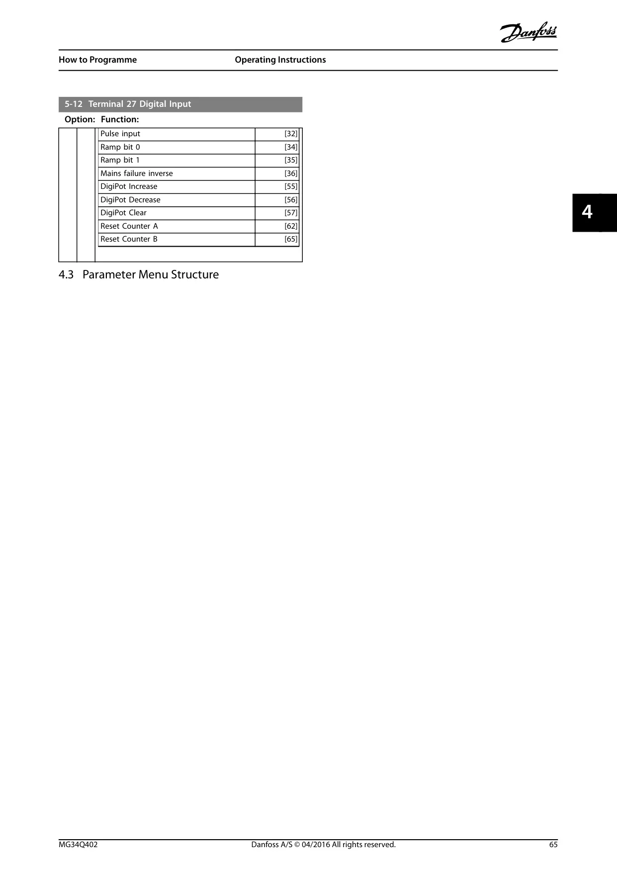
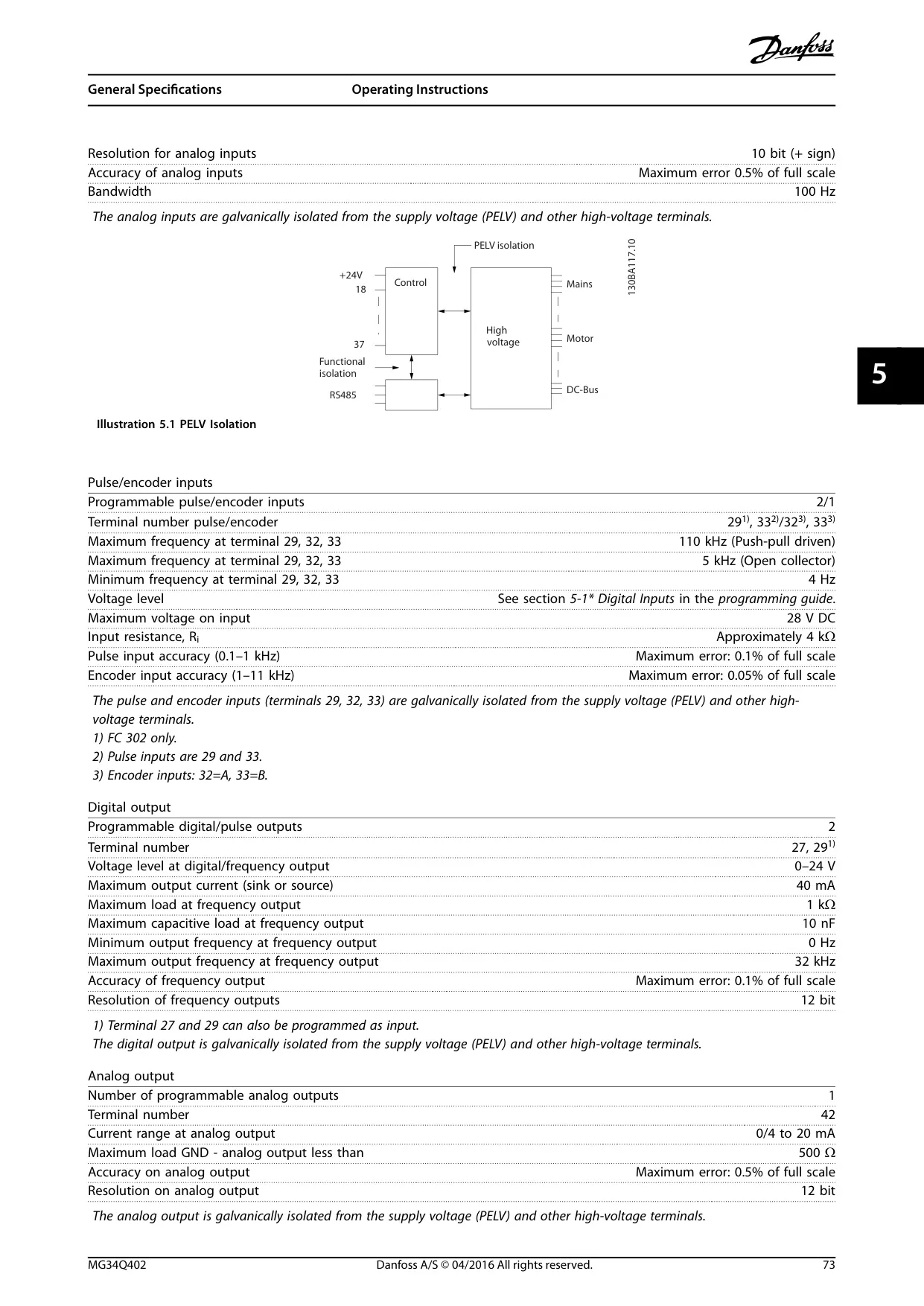
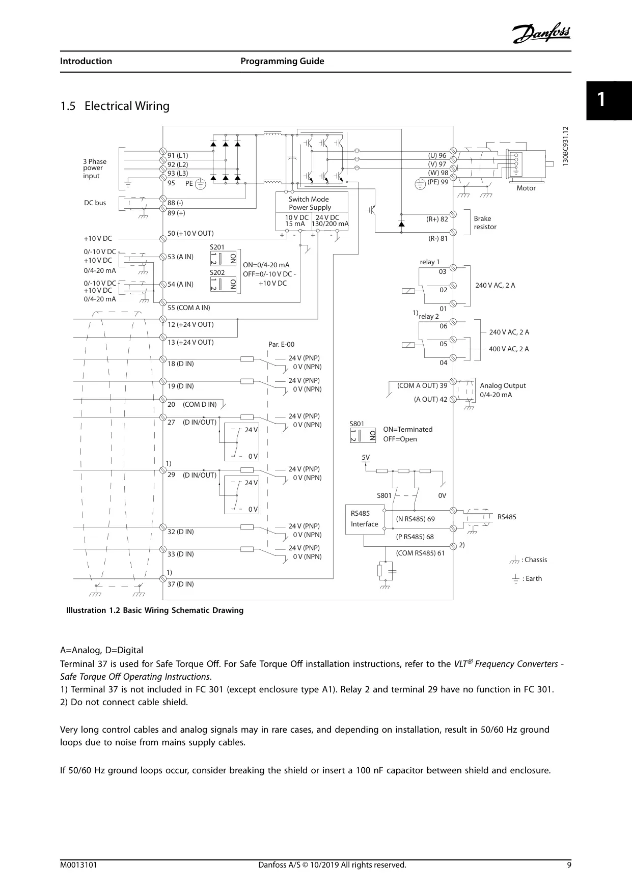
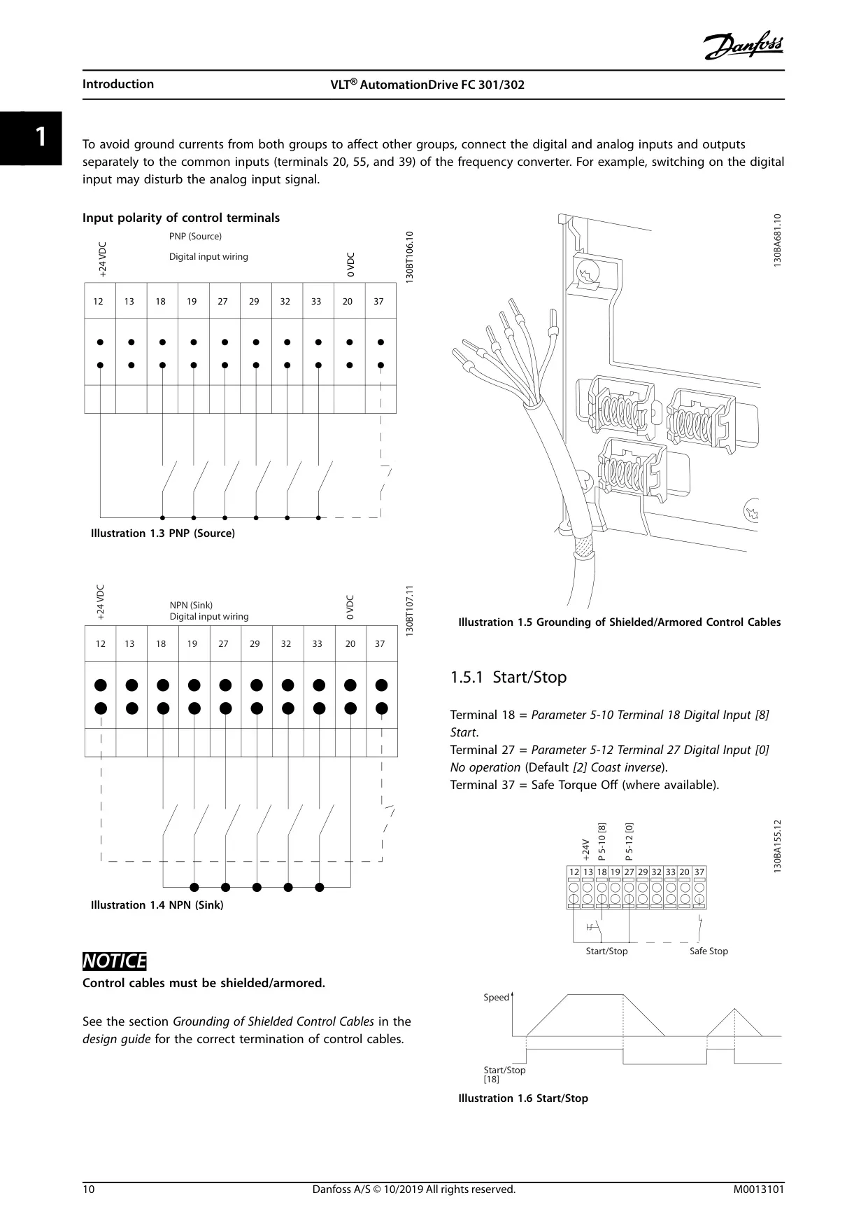
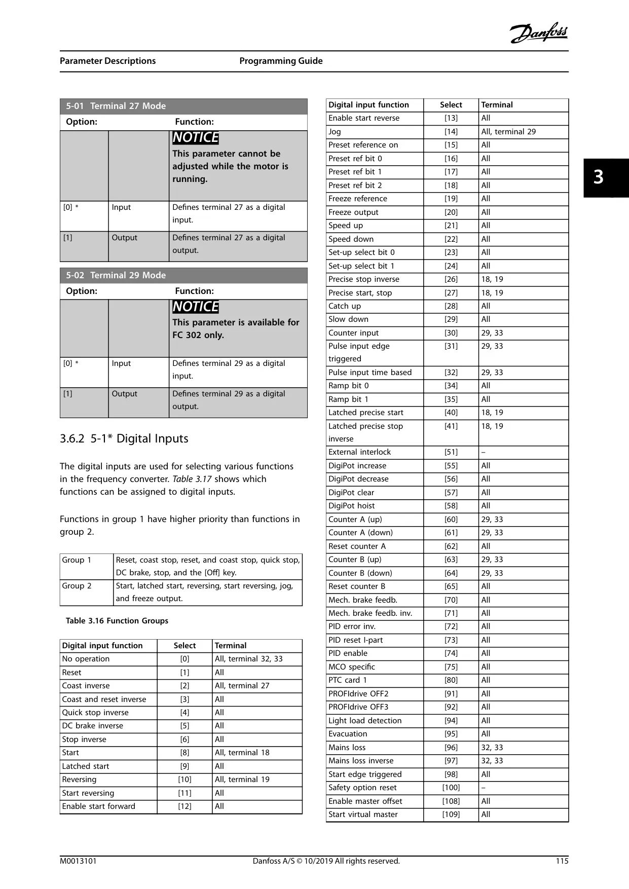
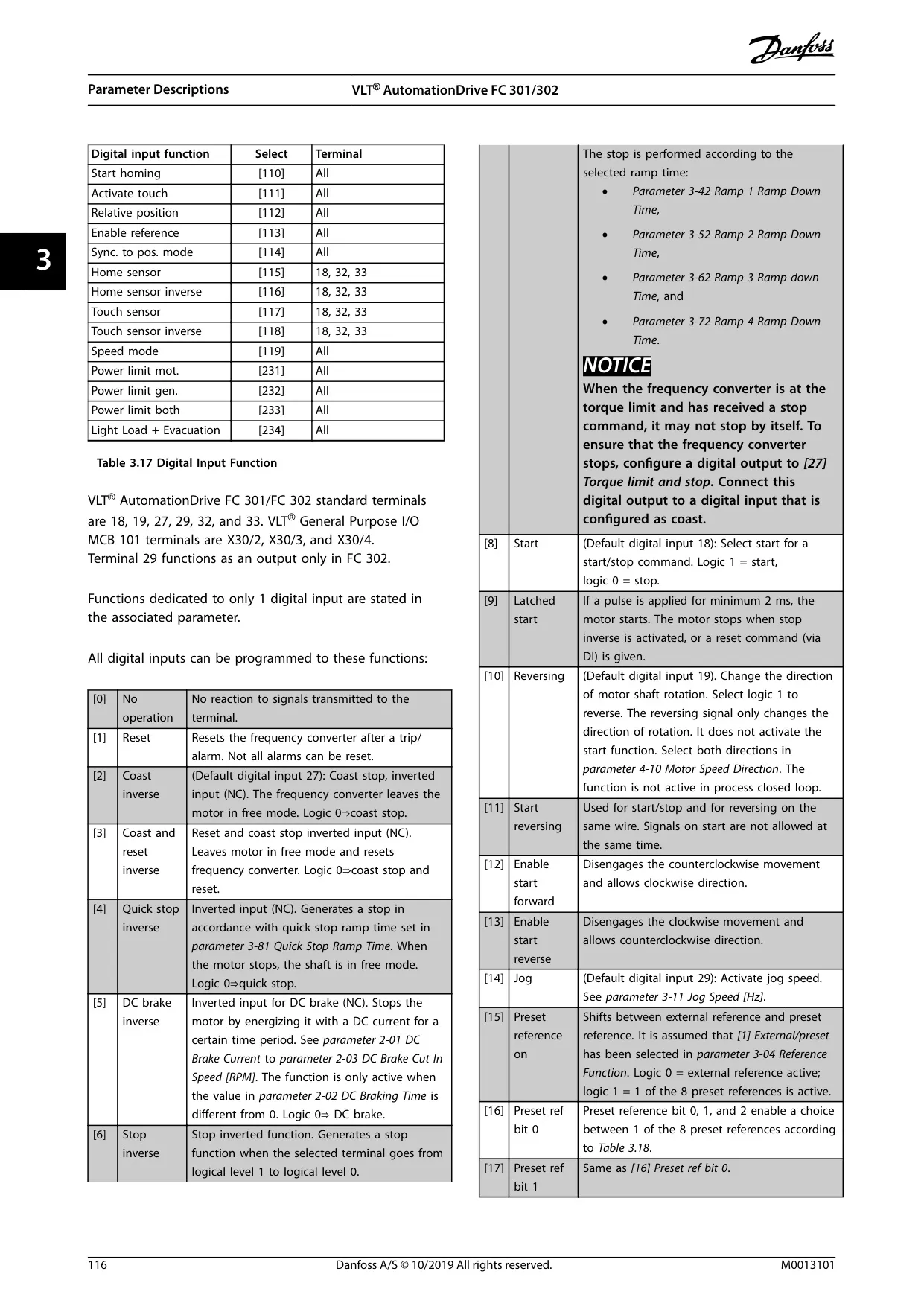
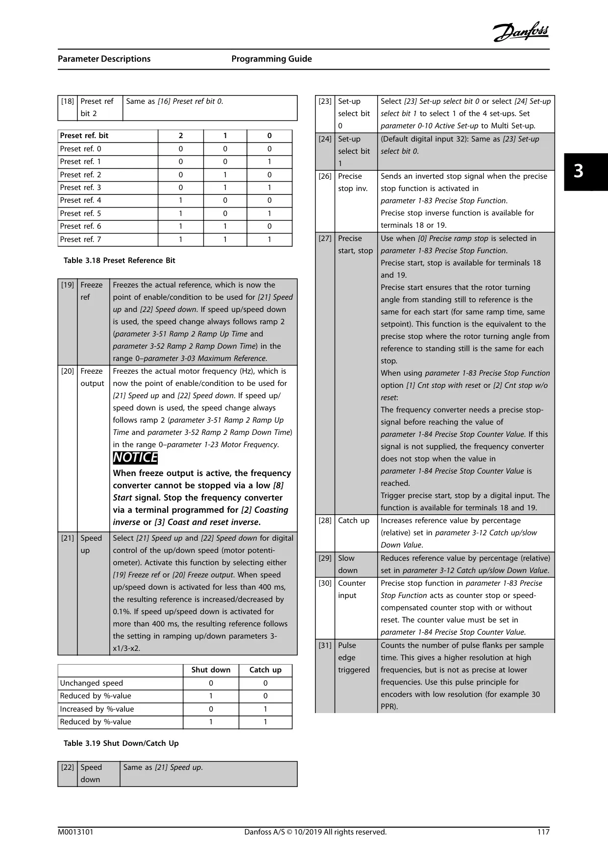
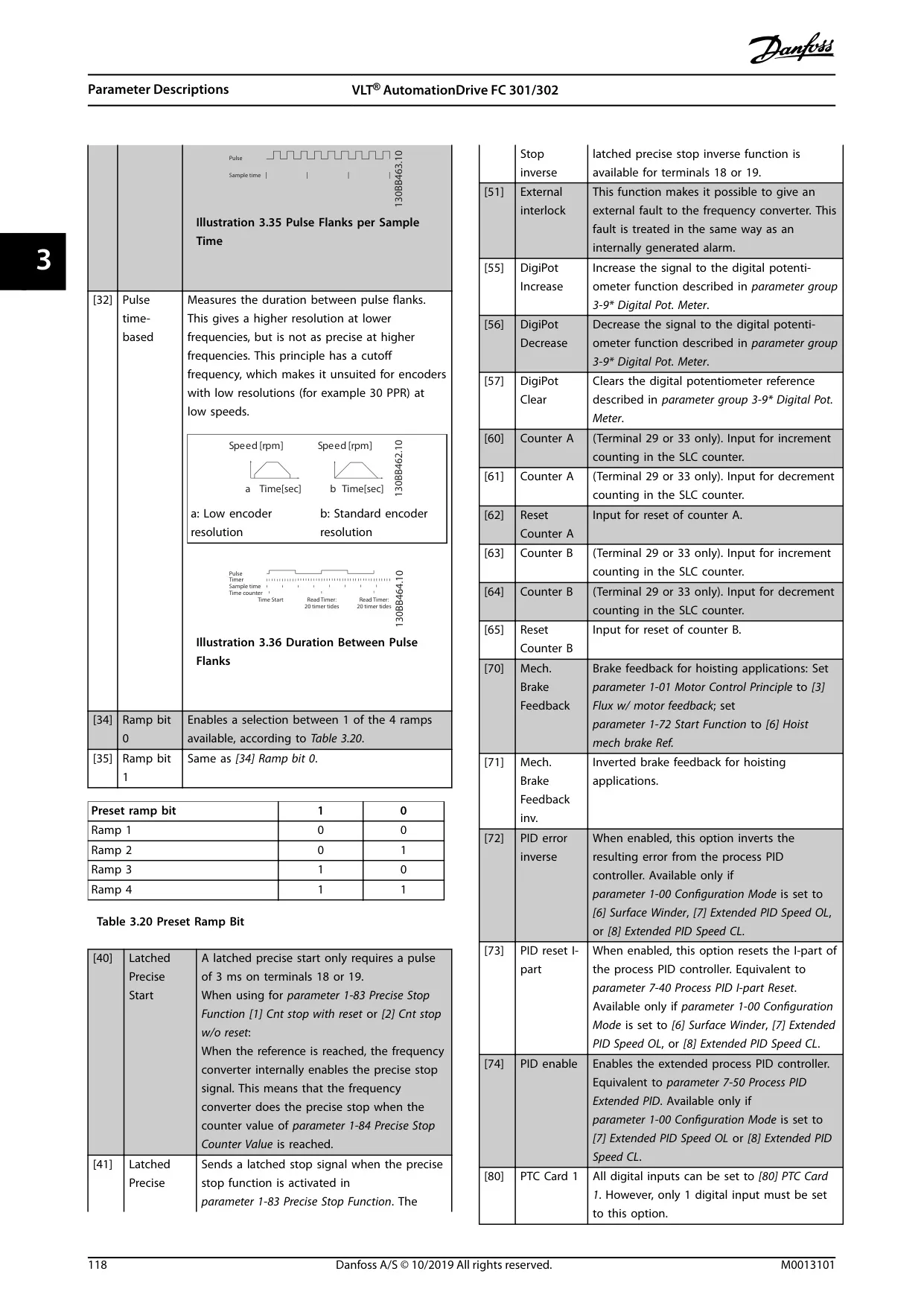
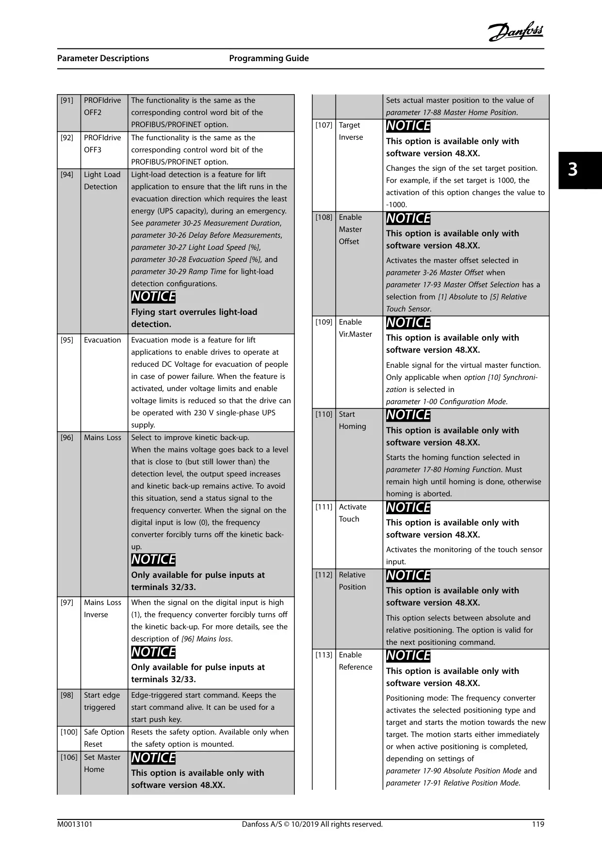
| Digital Inputs | 4 (programmable; 18, 19, 32, 33), with 2 additional (27, 29) programmable as input/output | PNP or NPN logic, 0-24 V DC |
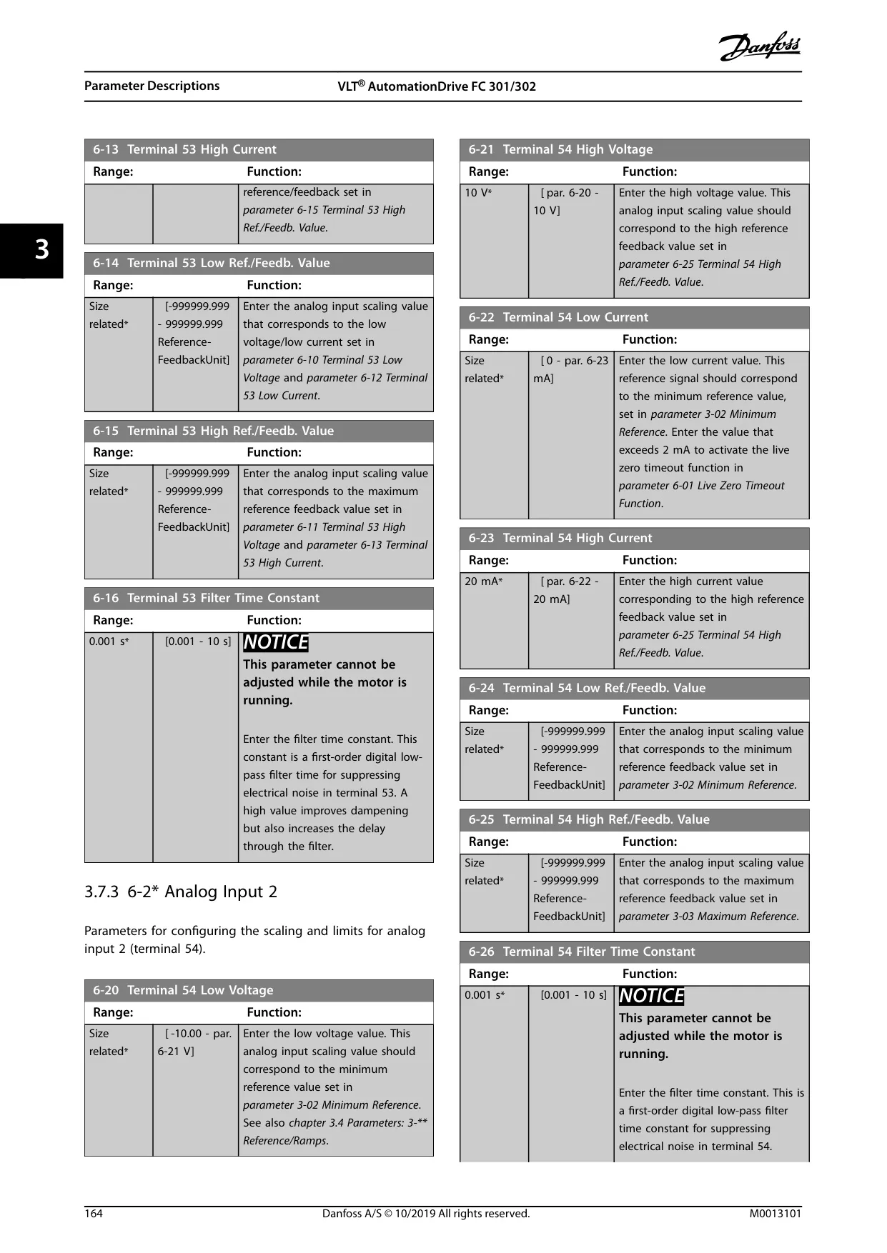
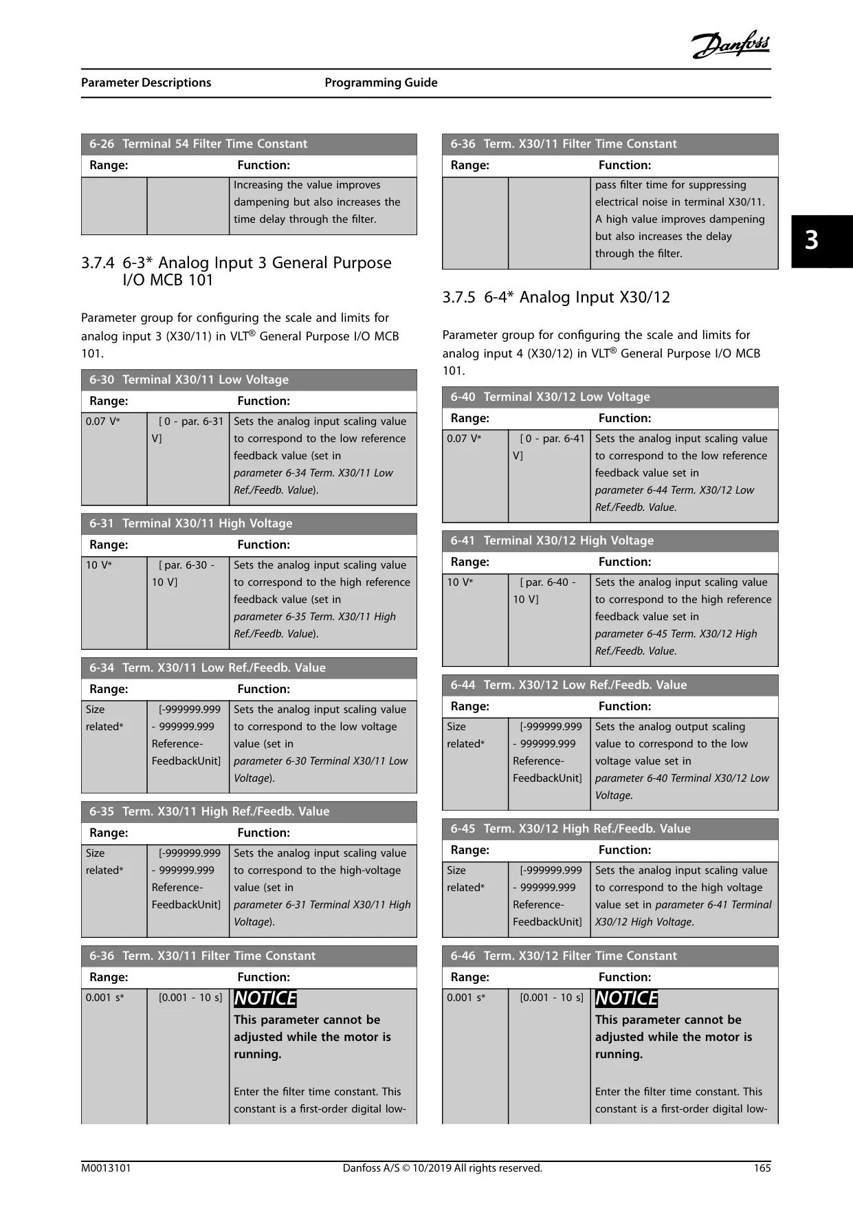
| Analog Inputs | 2 (53, 54), configurable for voltage (-10V to +10V) or current (0/4-20mA) | 10-bit resolution, 0.5% max error |
| Digital/Pulse Outputs | 2 (27, 29), 0-24V, 40mA max current | Max frequency 32 kHz |
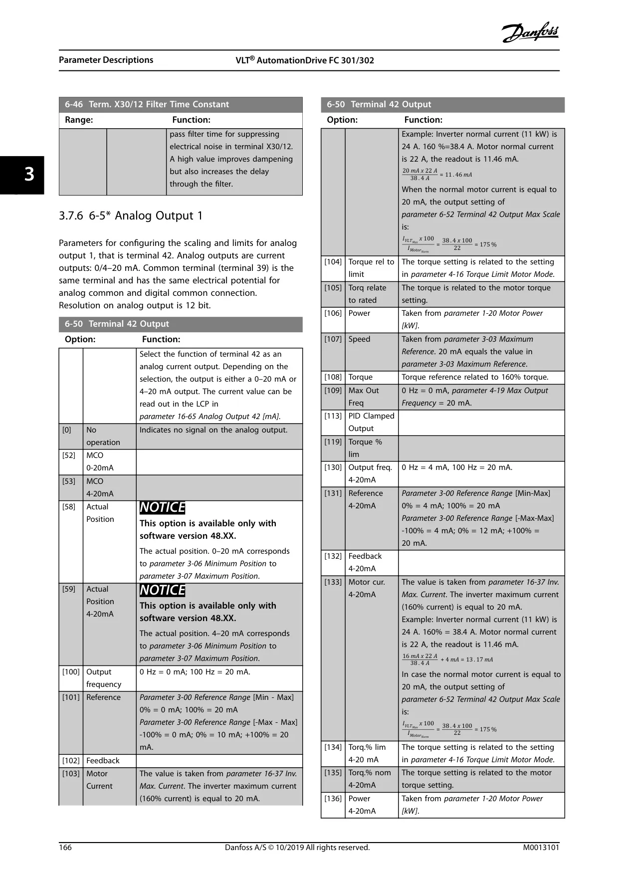
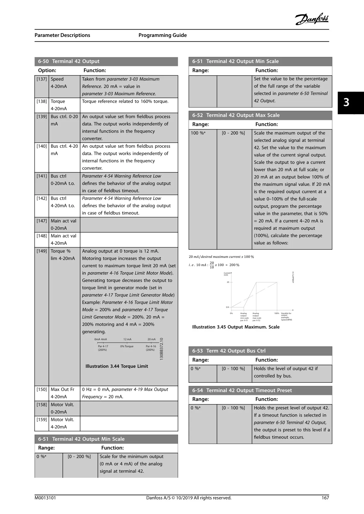
| Analog Outputs | 1 (42), 0/4-20mA current range | 12-bit resolution, 0.5% max error |
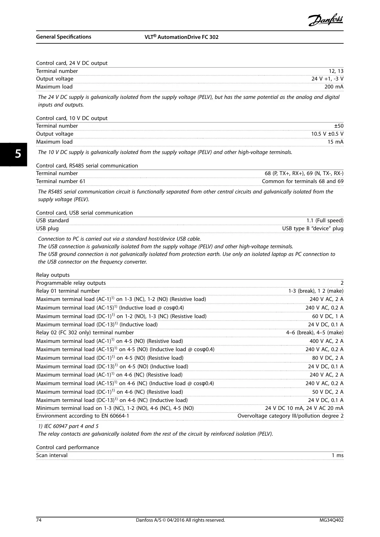
| Relay Outputs | 2 programmable (Relay 01, Relay 02) | Galvanically isolated, up to 400V AC, 2A / 80V DC, 2A |
| Control Card DC Output (24V) | 24 V +1, -3 V, 200 mA max load | For auxiliary control components |
| Control Card DC Output (10V) | 10.5 V ±0.5 V, 15 mA max load | For potentiometers and reference signals |
| Communication Interfaces | RS485 serial communication, USB serial communication | Galvanically isolated for reliability |
| Efficiency | Typically 0.98 | High energy efficiency |
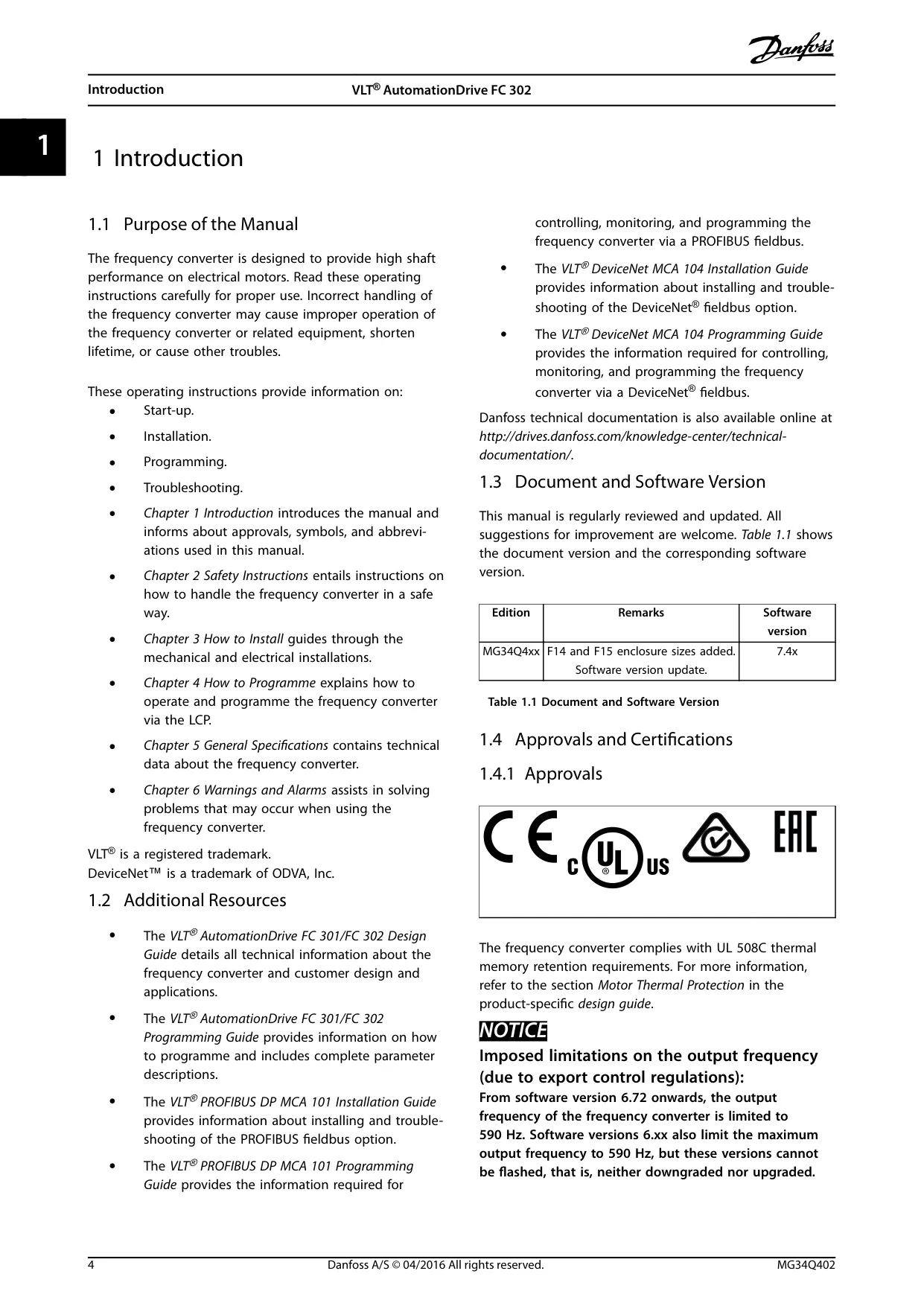
| Approvals & Certifications | UL 508C, CE (for 1400–2000 kW, 690 V models) | Complies with safety and performance standards |
Danfoss FC-302 VFD Details
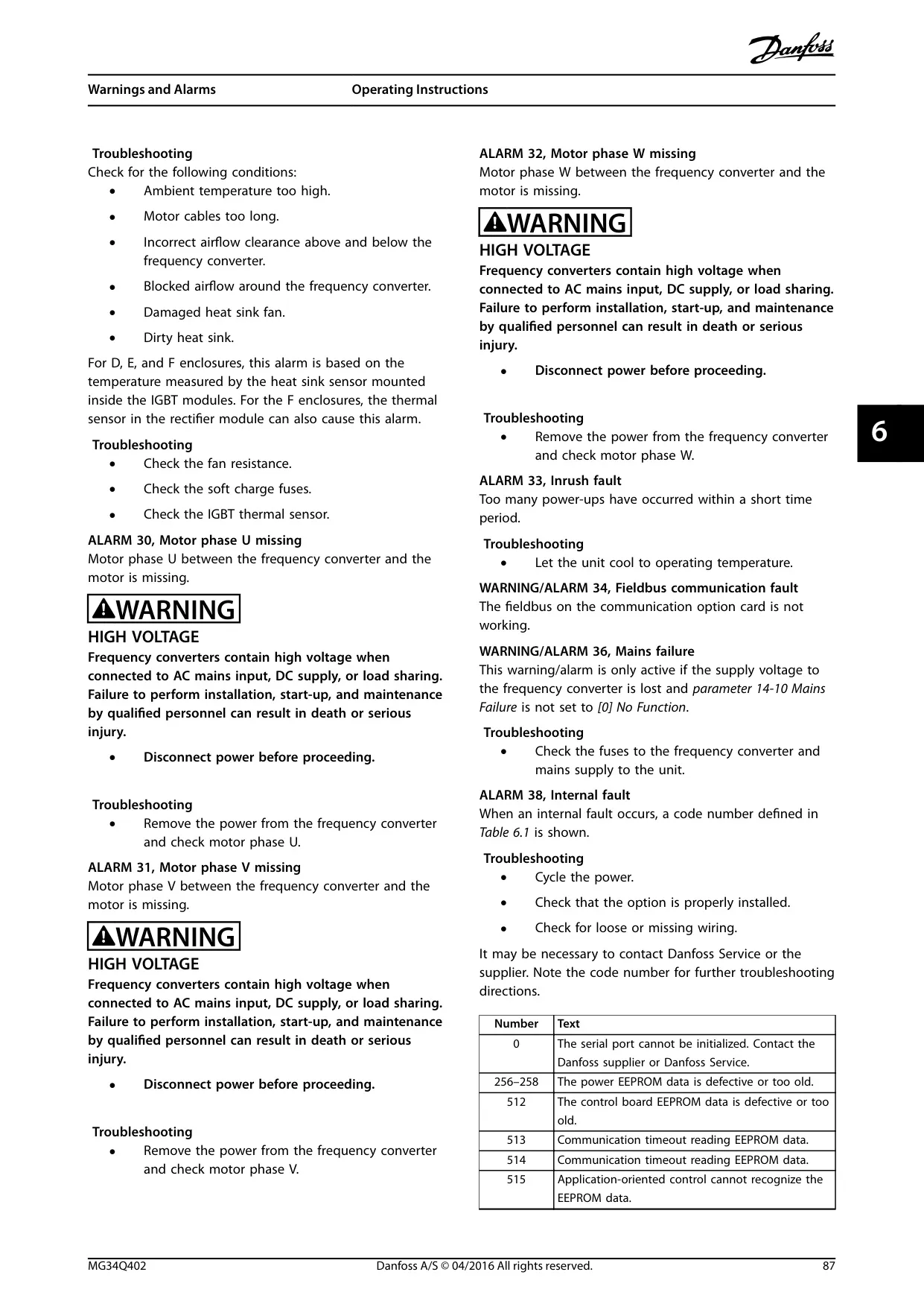
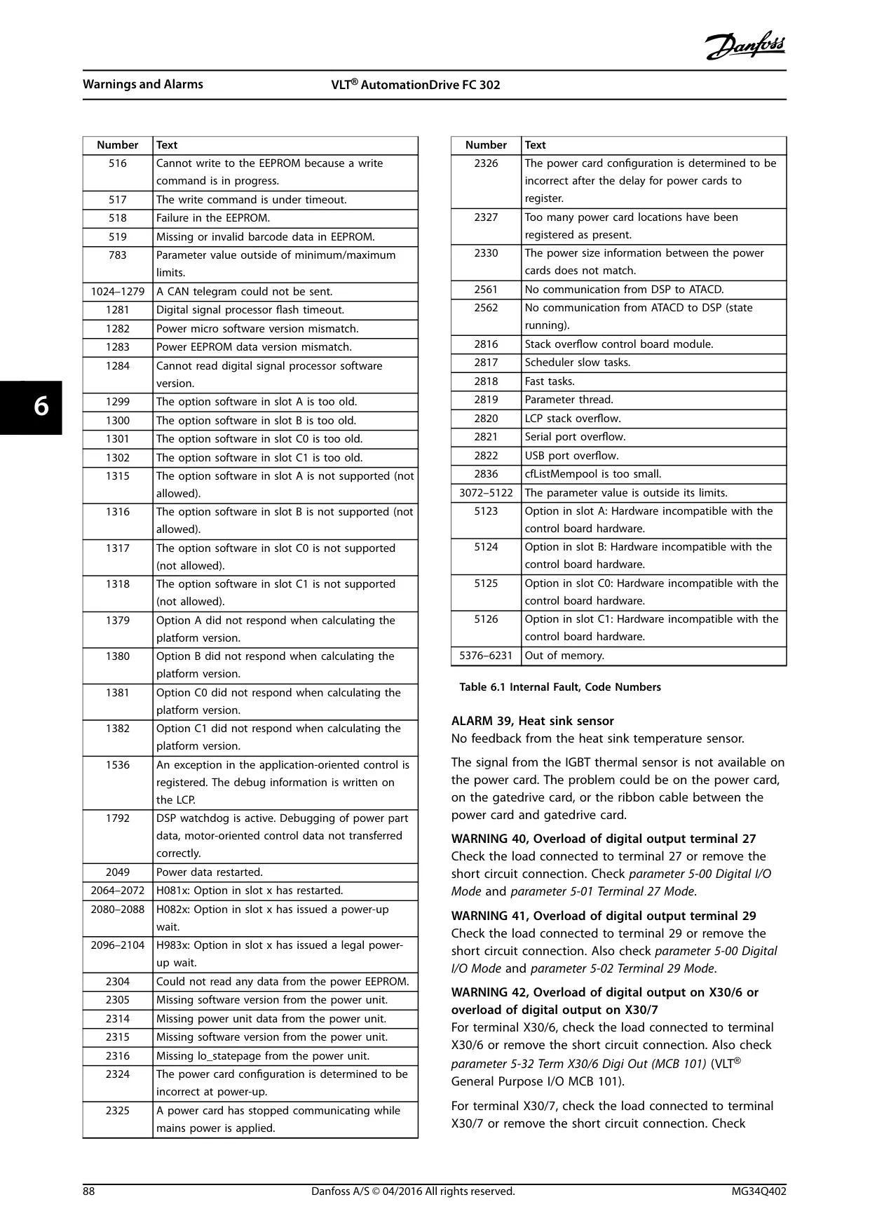
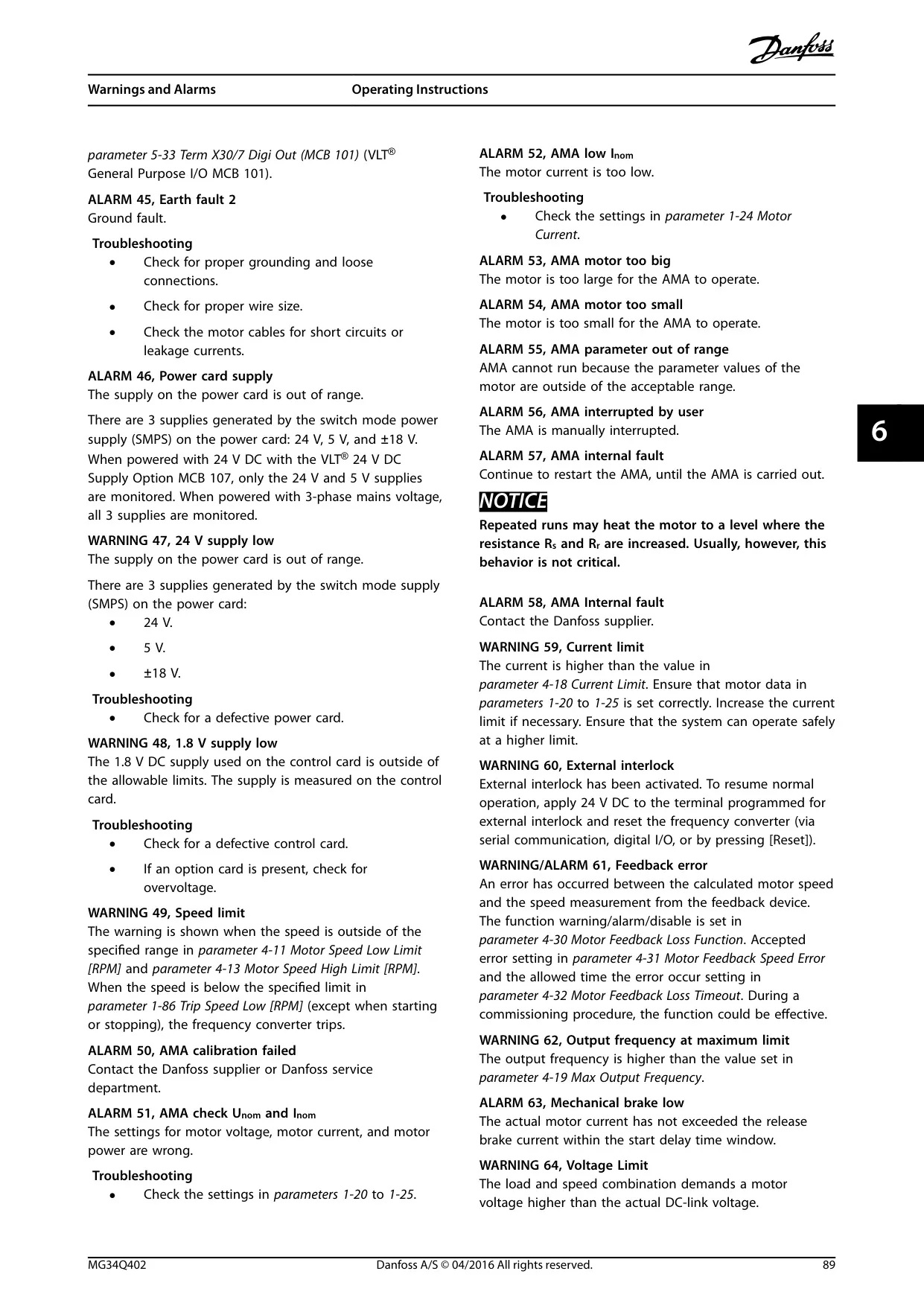
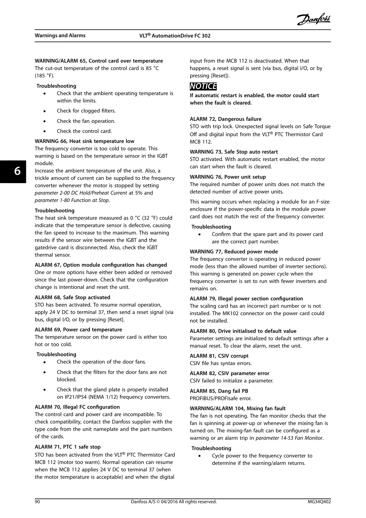
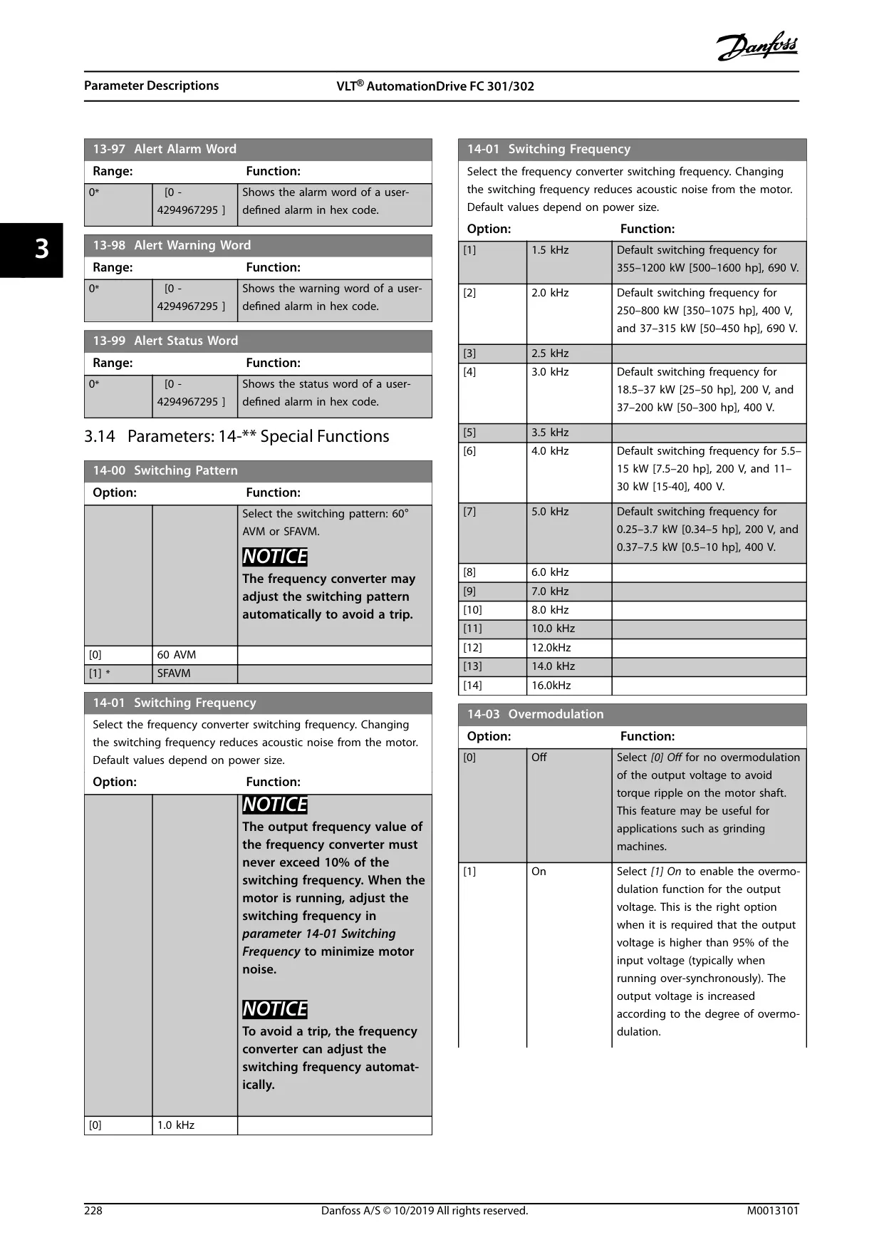
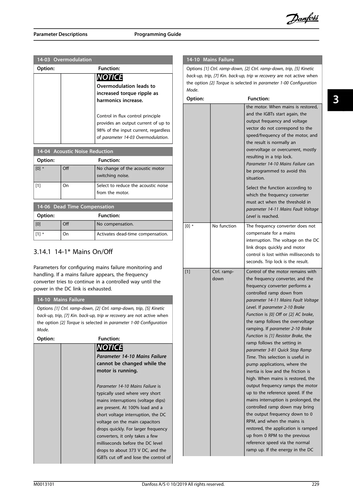
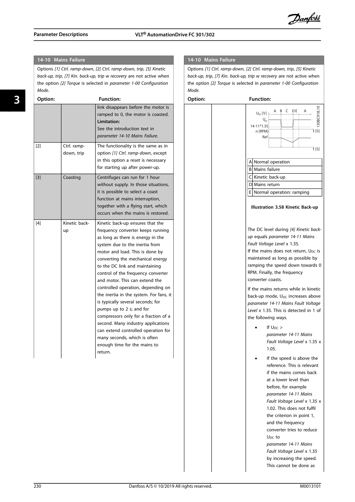
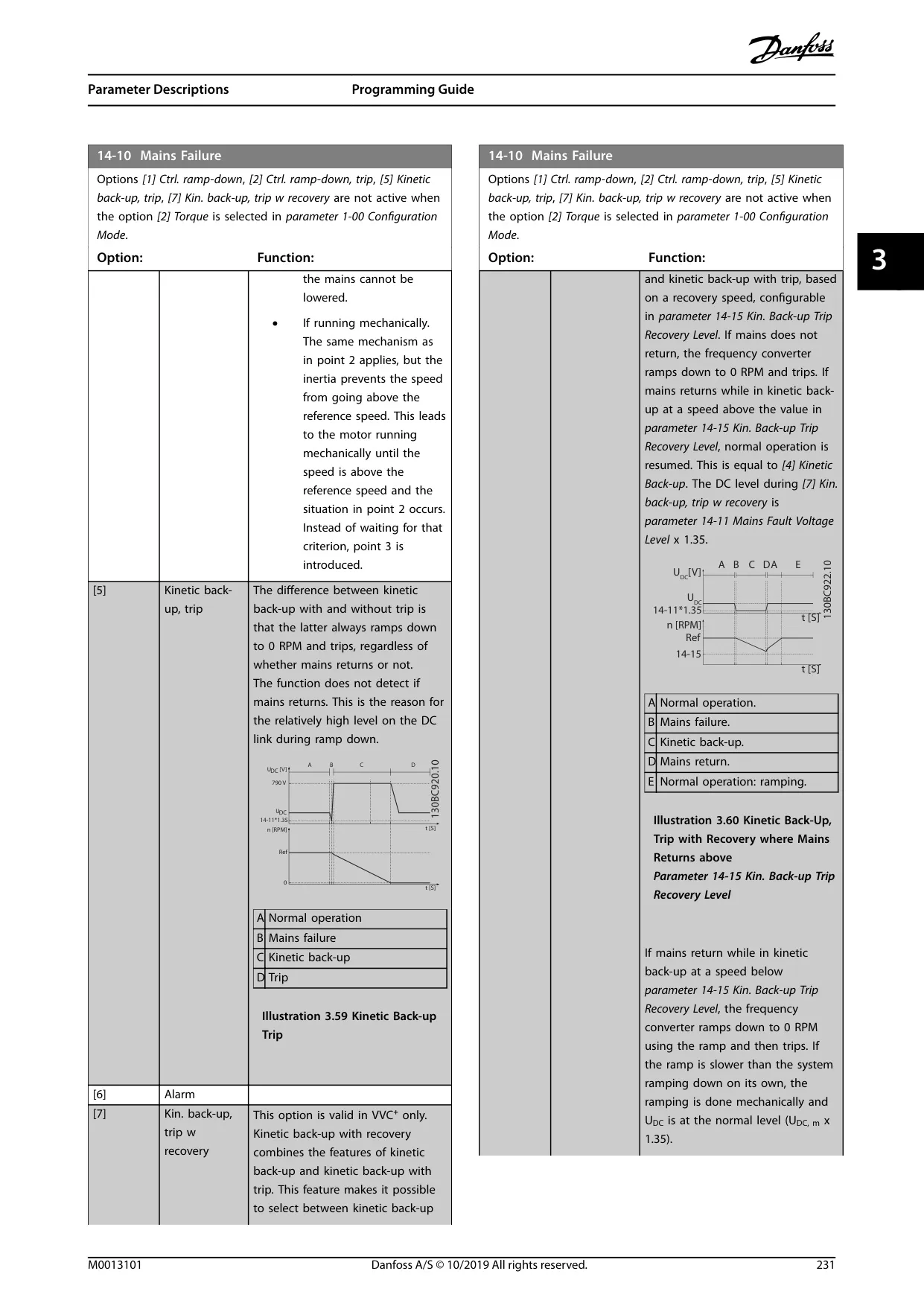
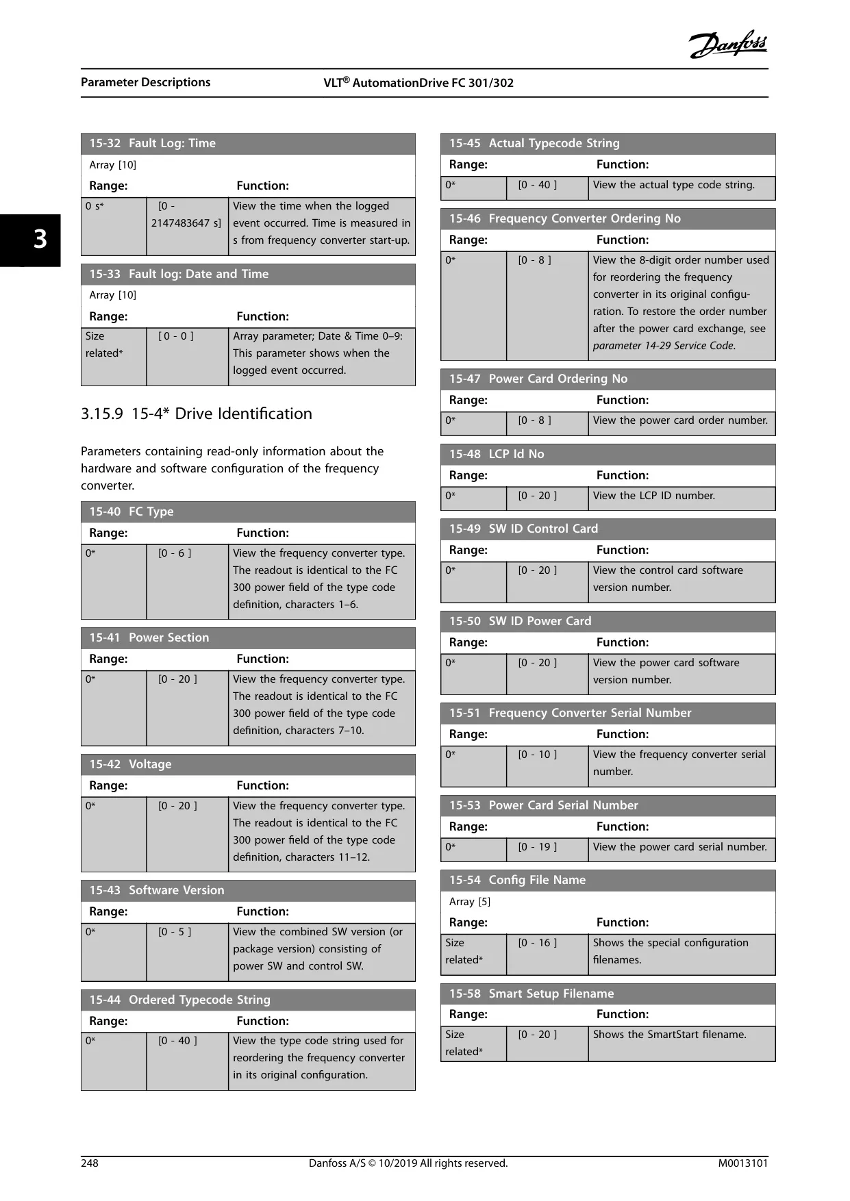
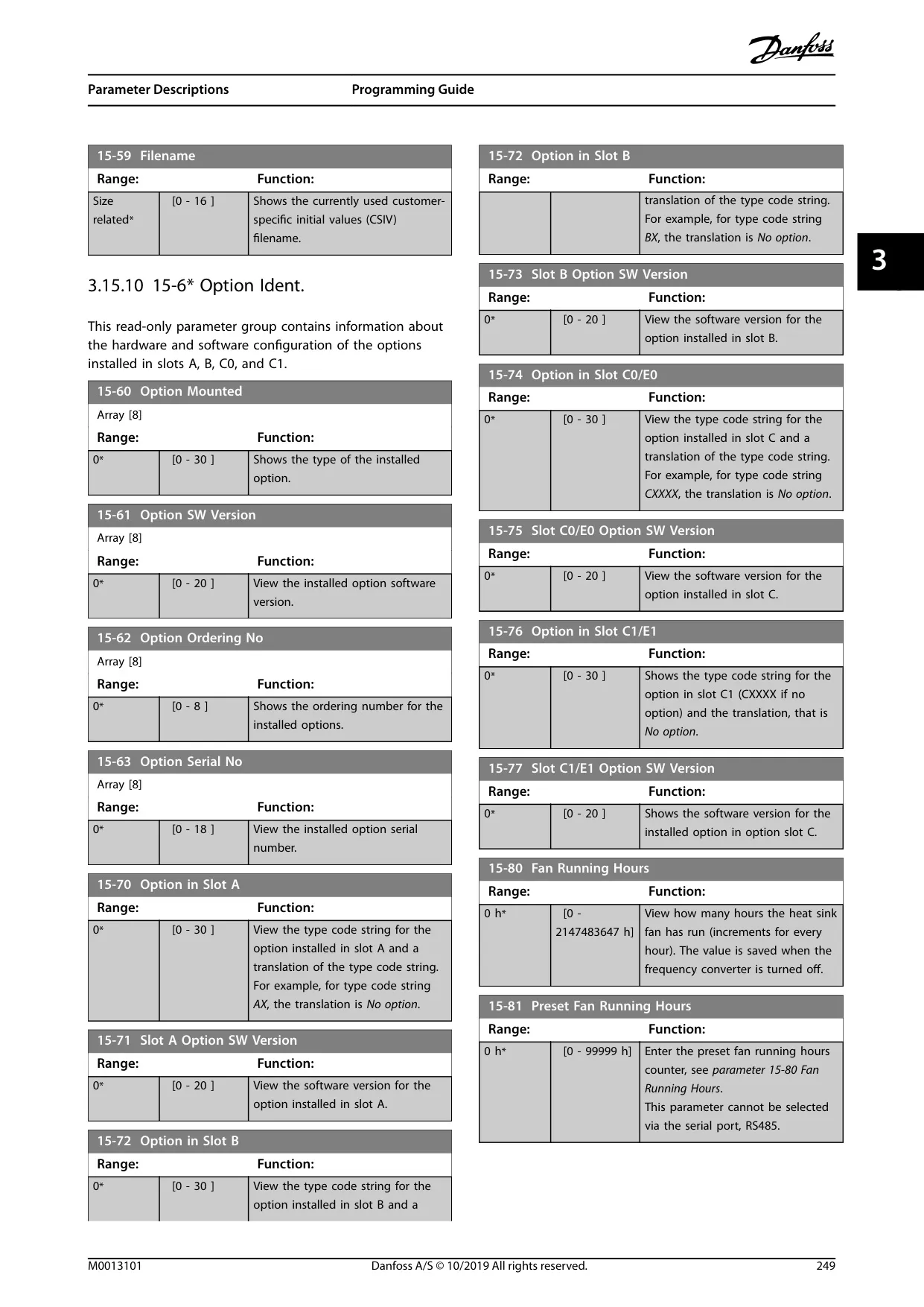
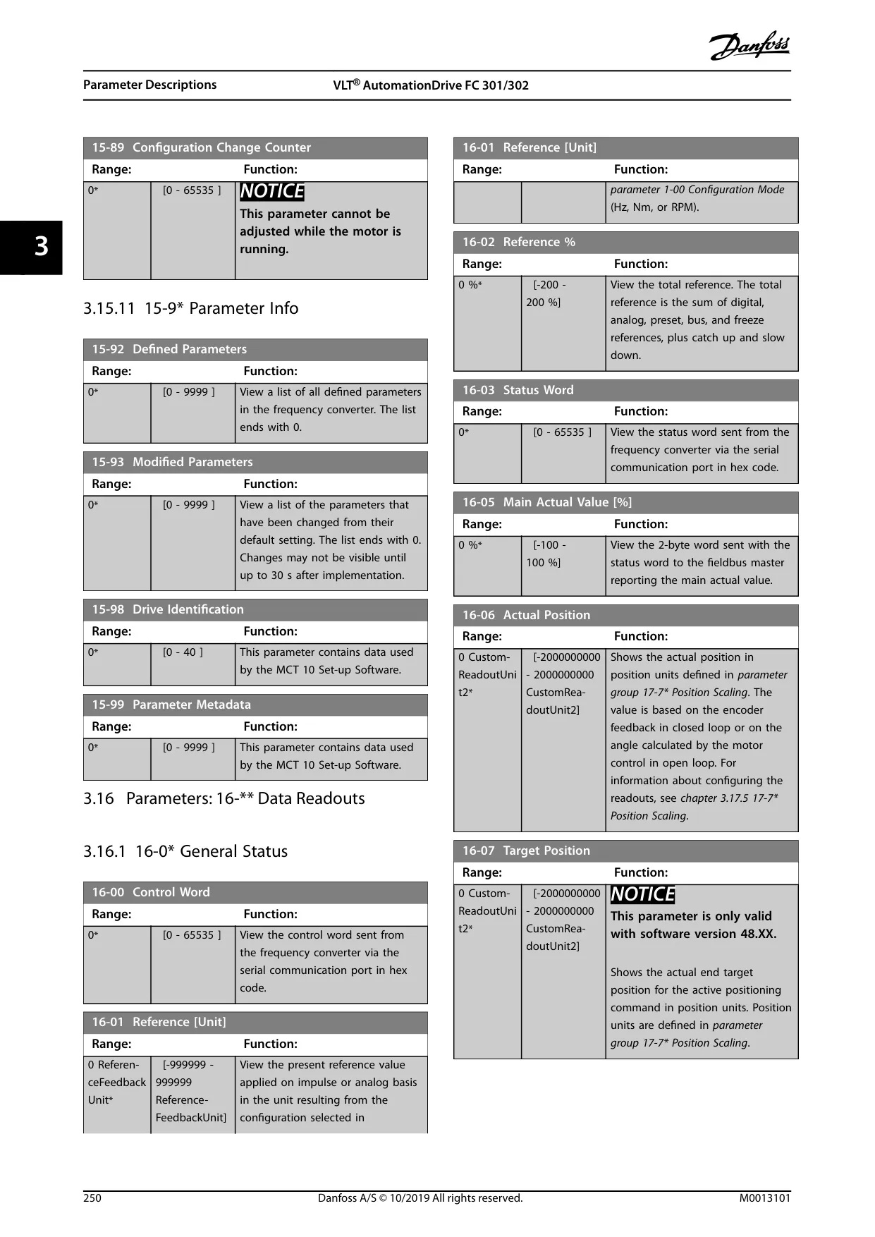
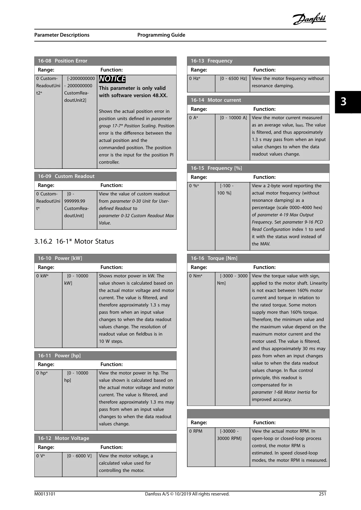
The Danfoss FC-302 VLT AutomationDrive is engineered to deliver high shaft performance for electric motors, crucial for industrial applications. Proper handling and adherence to operating instructions are essential to prevent malfunction, shorten lifetime, or other operational issues. This guide serves as a comprehensive resource for installation, programming, start-up, and troubleshooting, ensuring safe and efficient use.
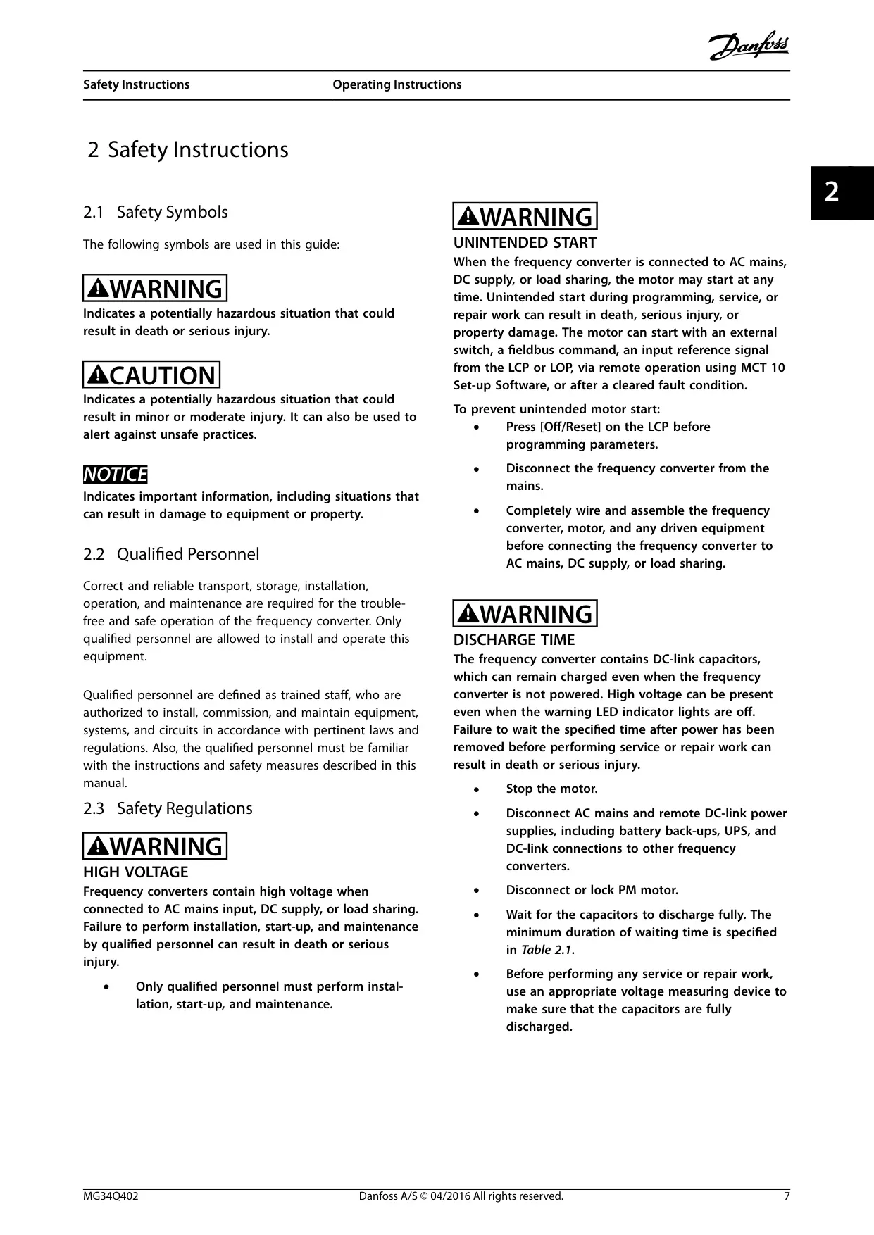
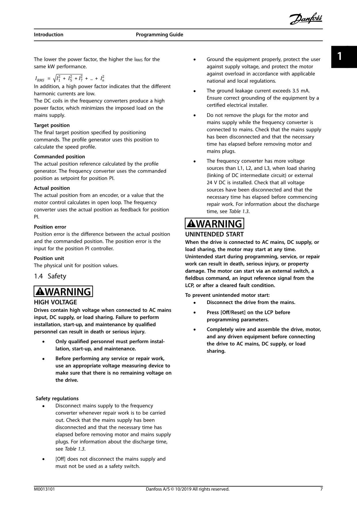
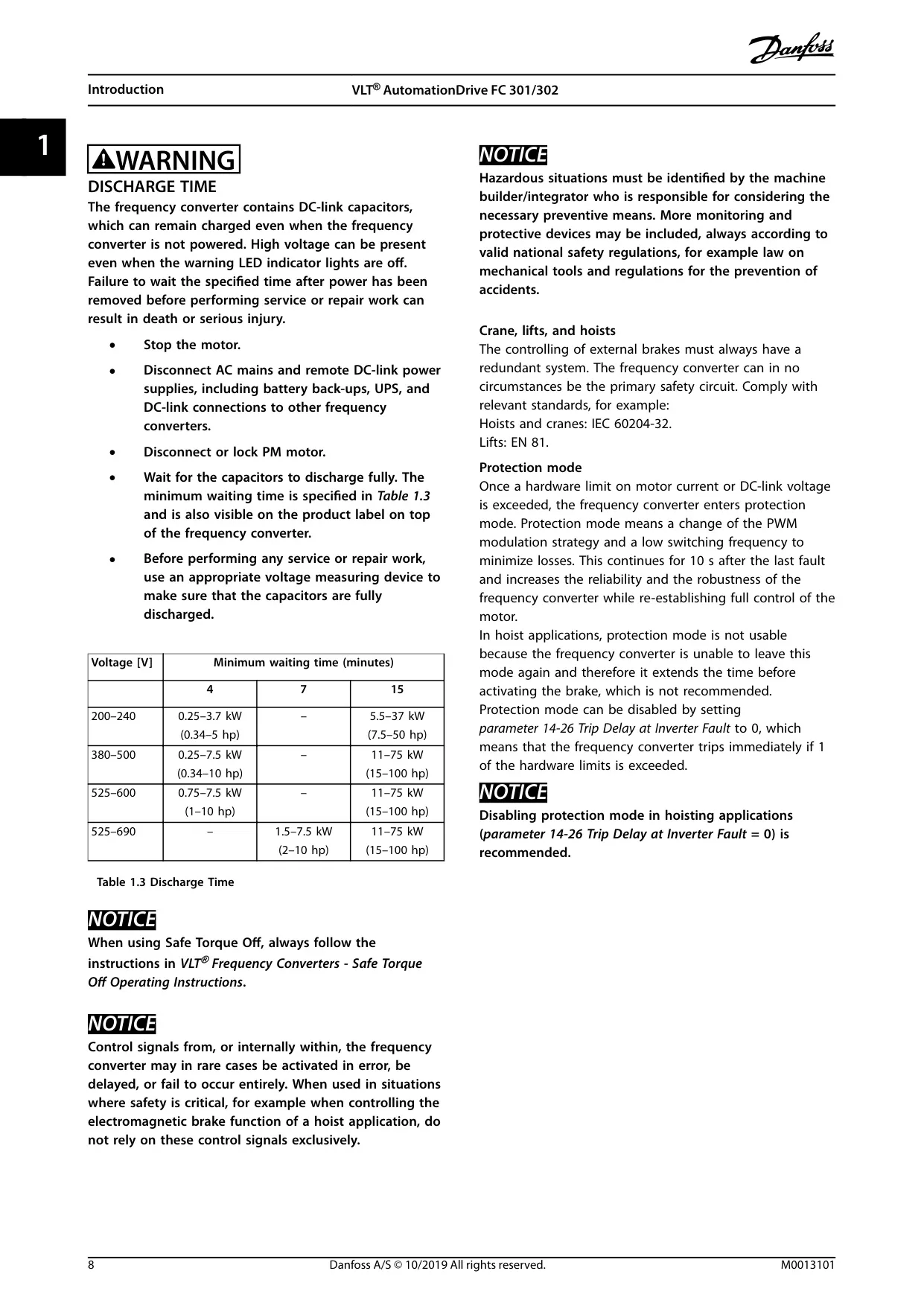
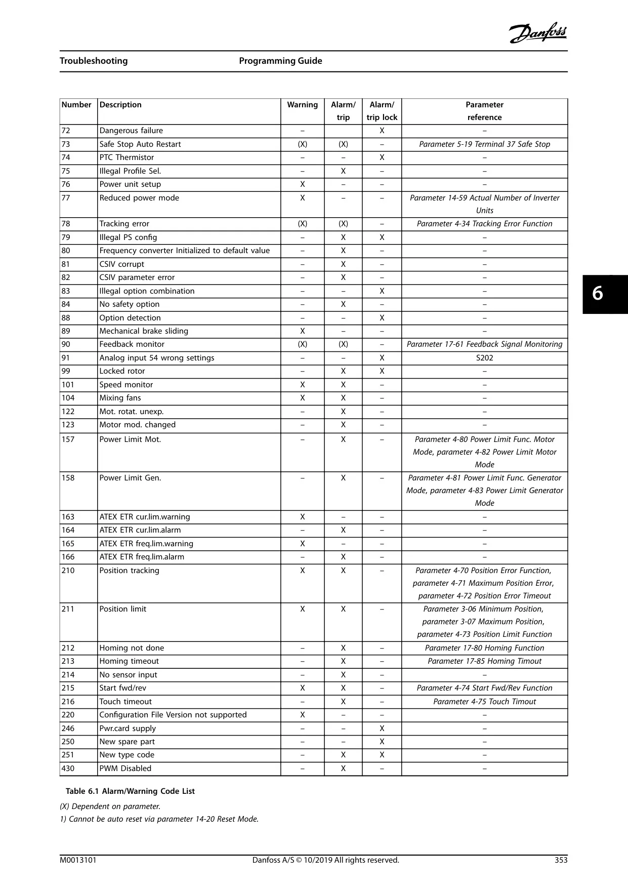
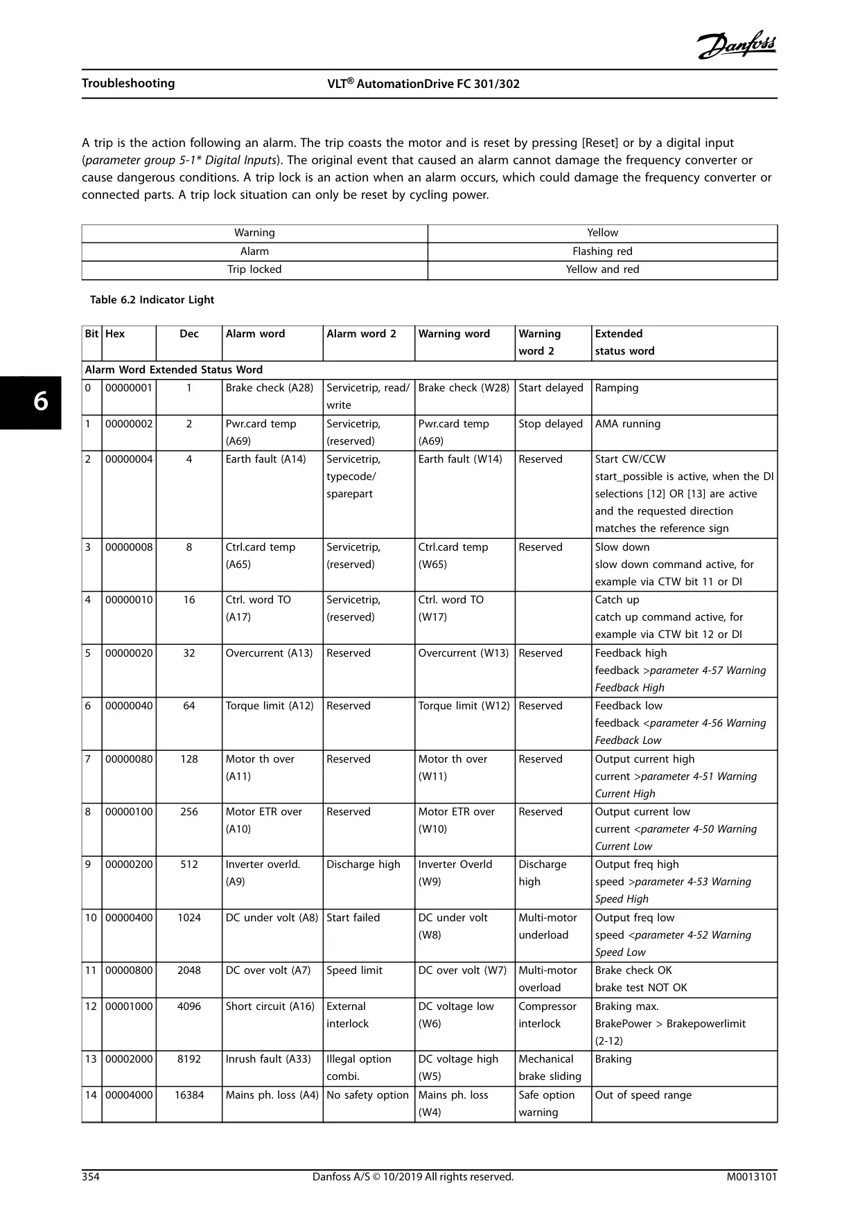
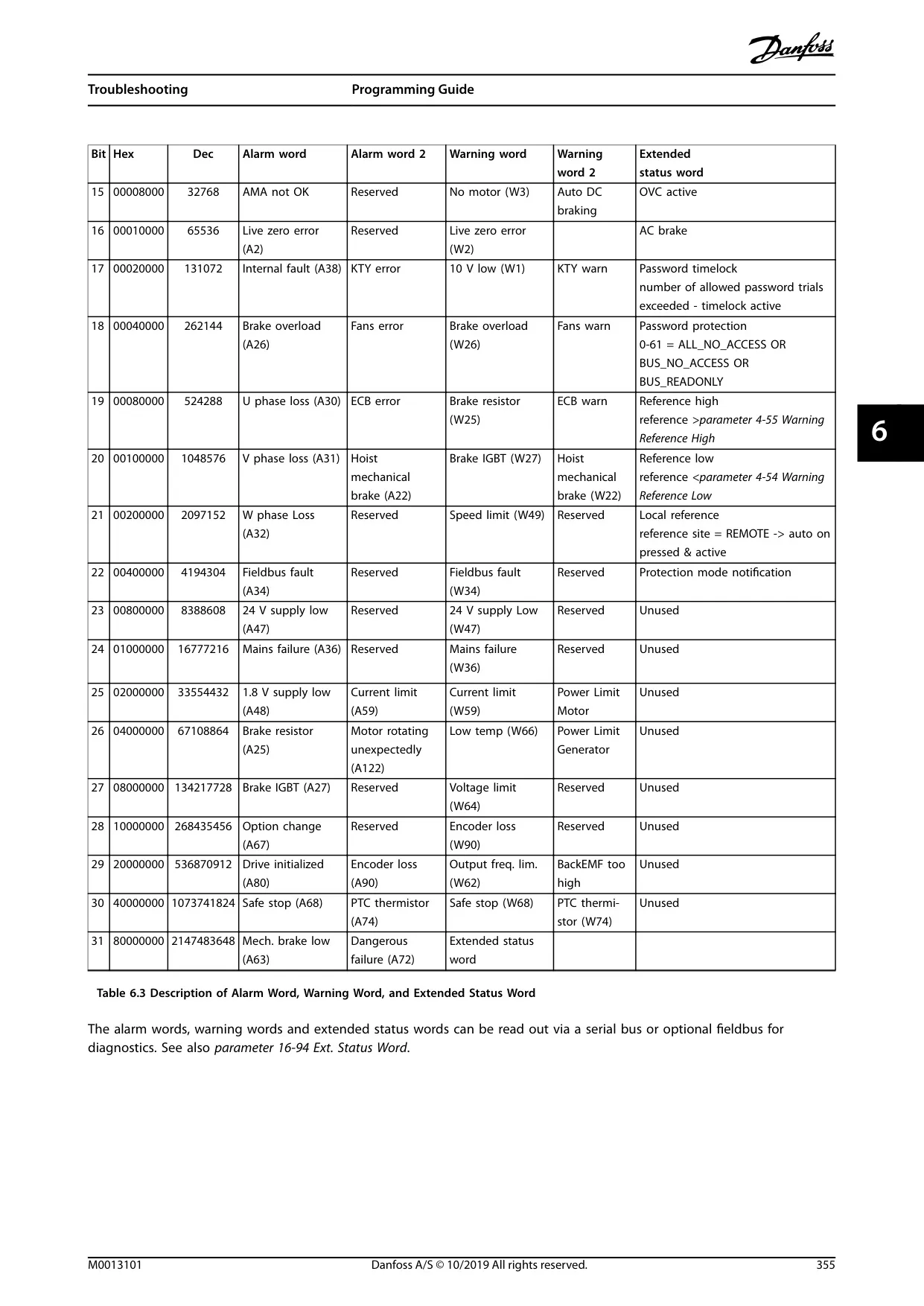
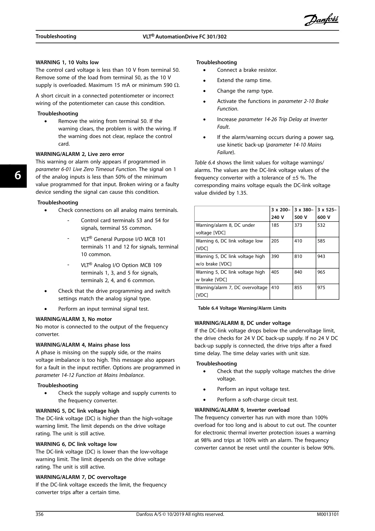
Safety is paramount, with strict guidelines for qualified personnel to handle installation, start-up, and maintenance. The drive utilizes robust safety symbols for warnings and cautions. It also integrates a critical safety feature: Safe Torque Off (STO), requiring specific wiring and procedures detailed in supplementary documentation.
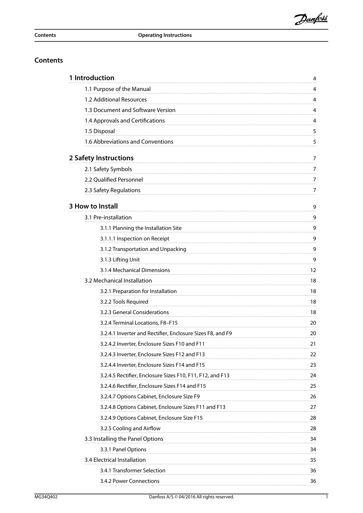
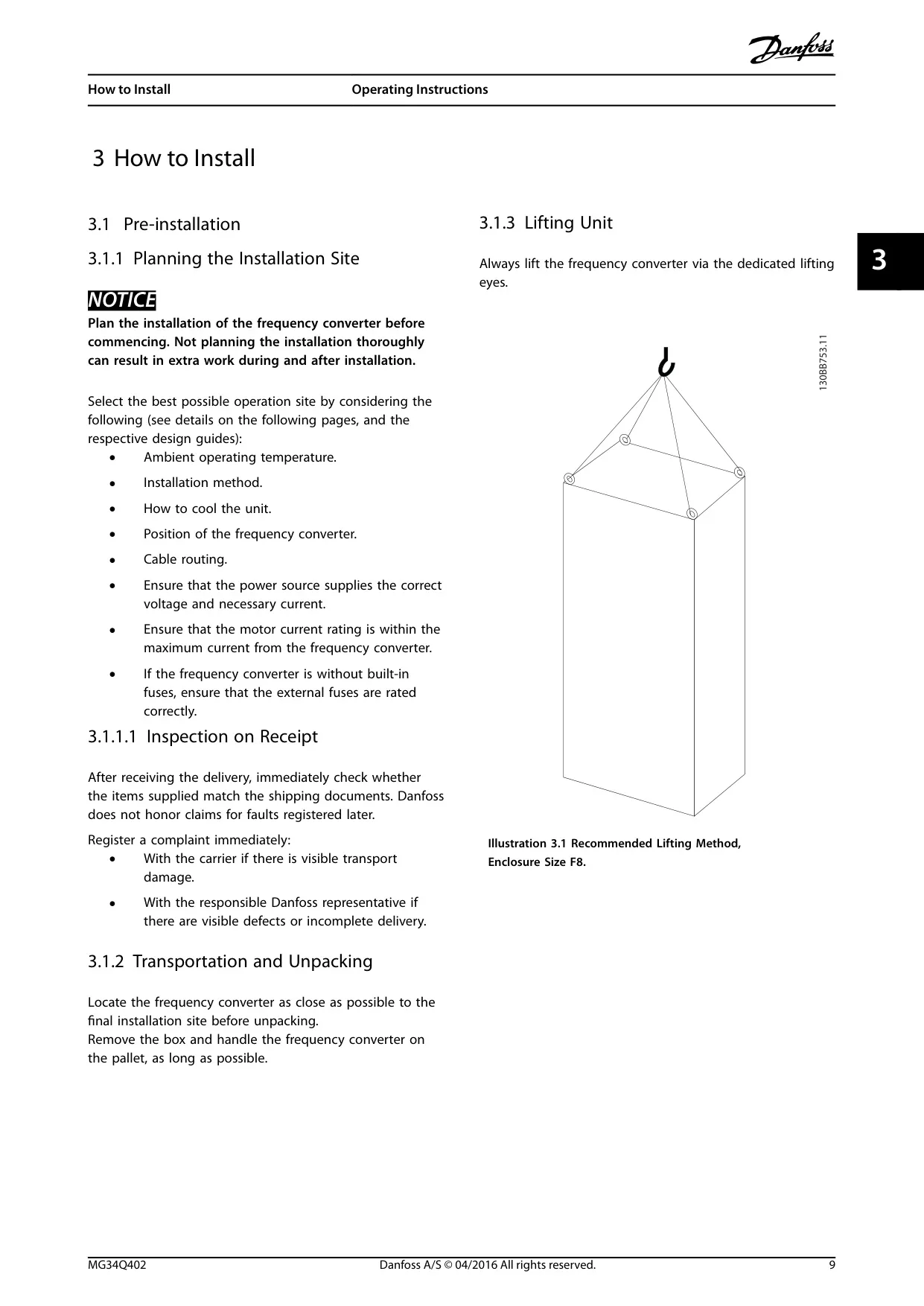
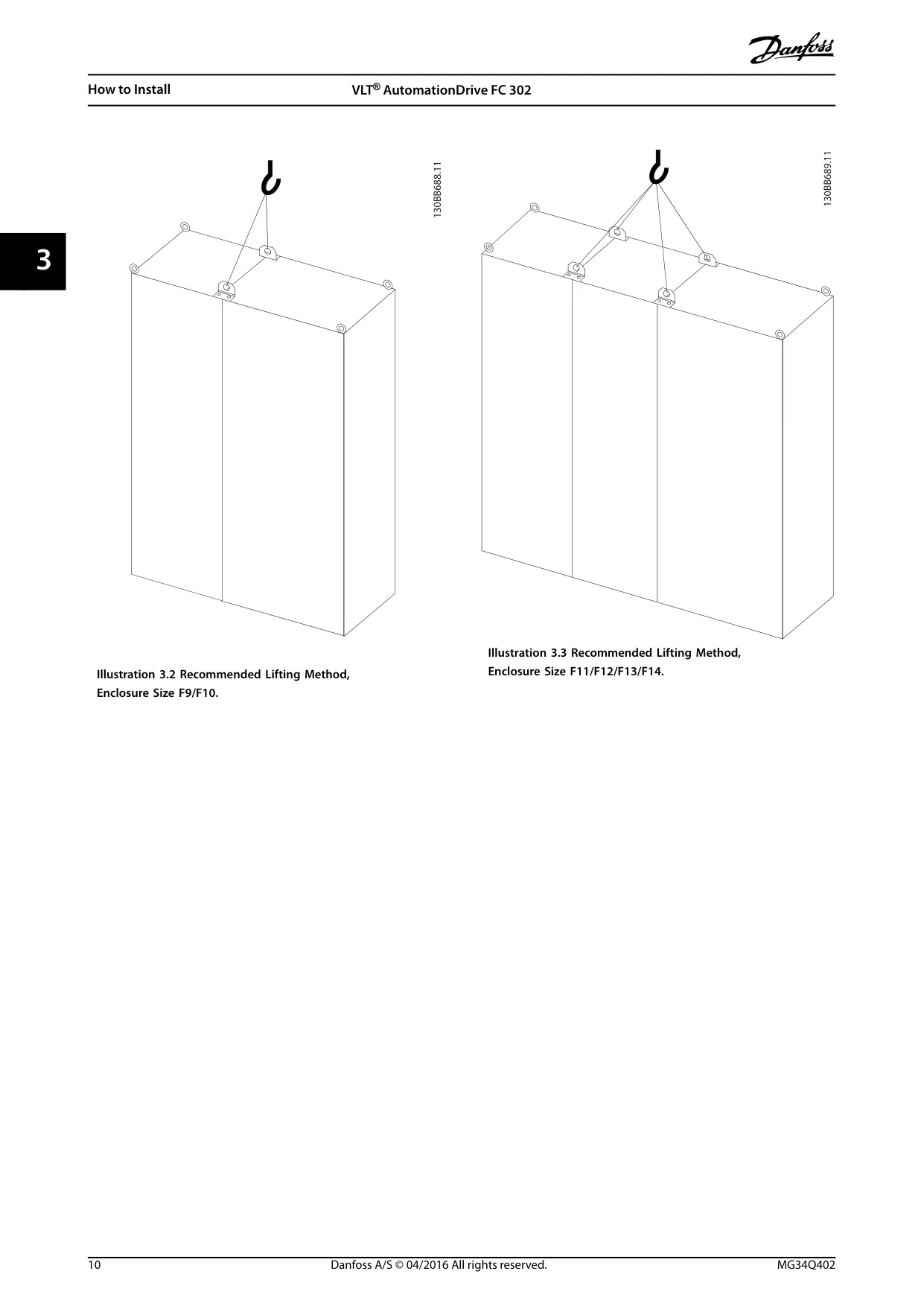
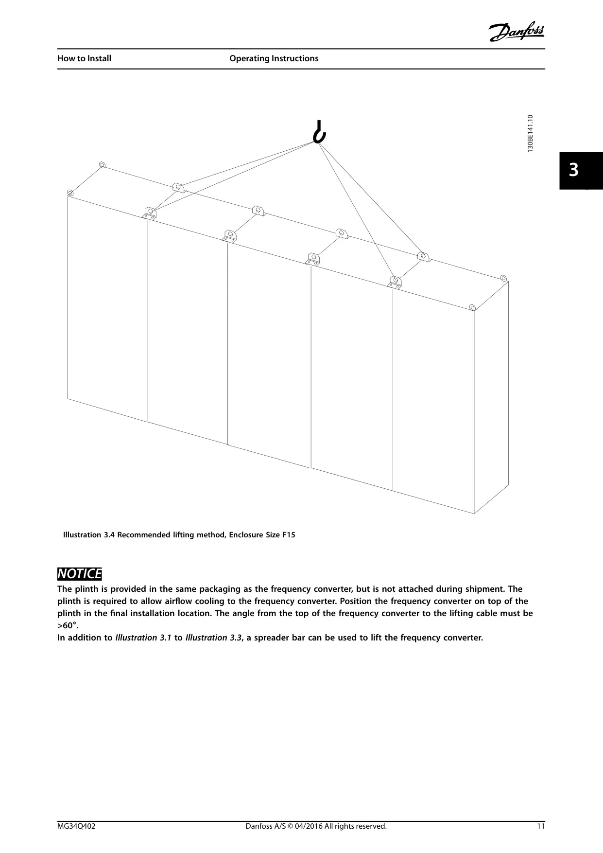
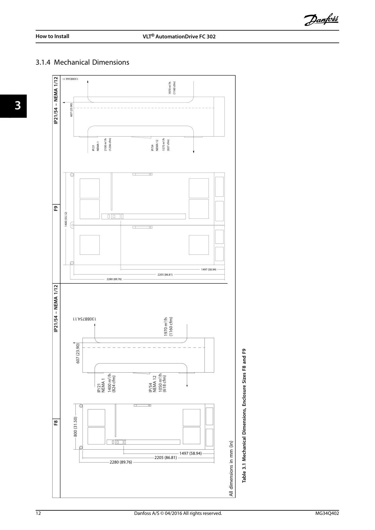
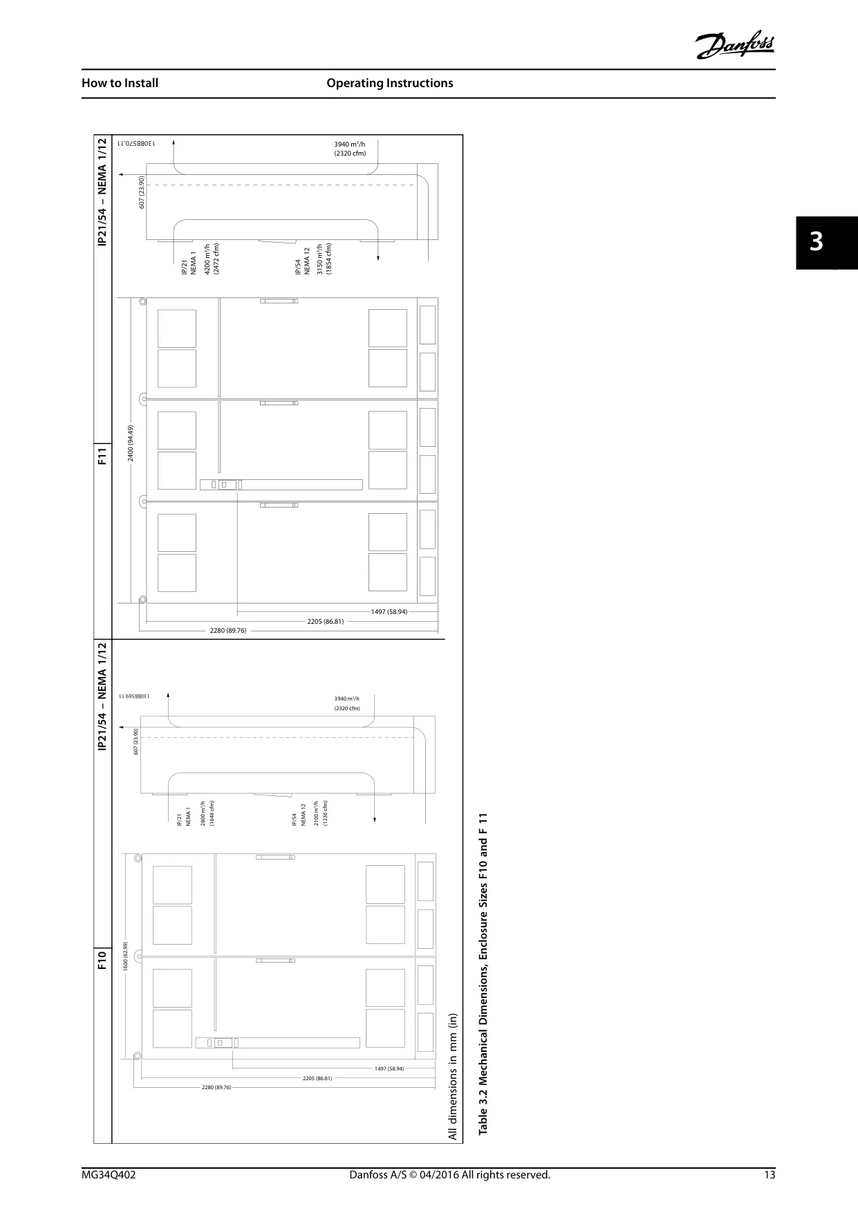
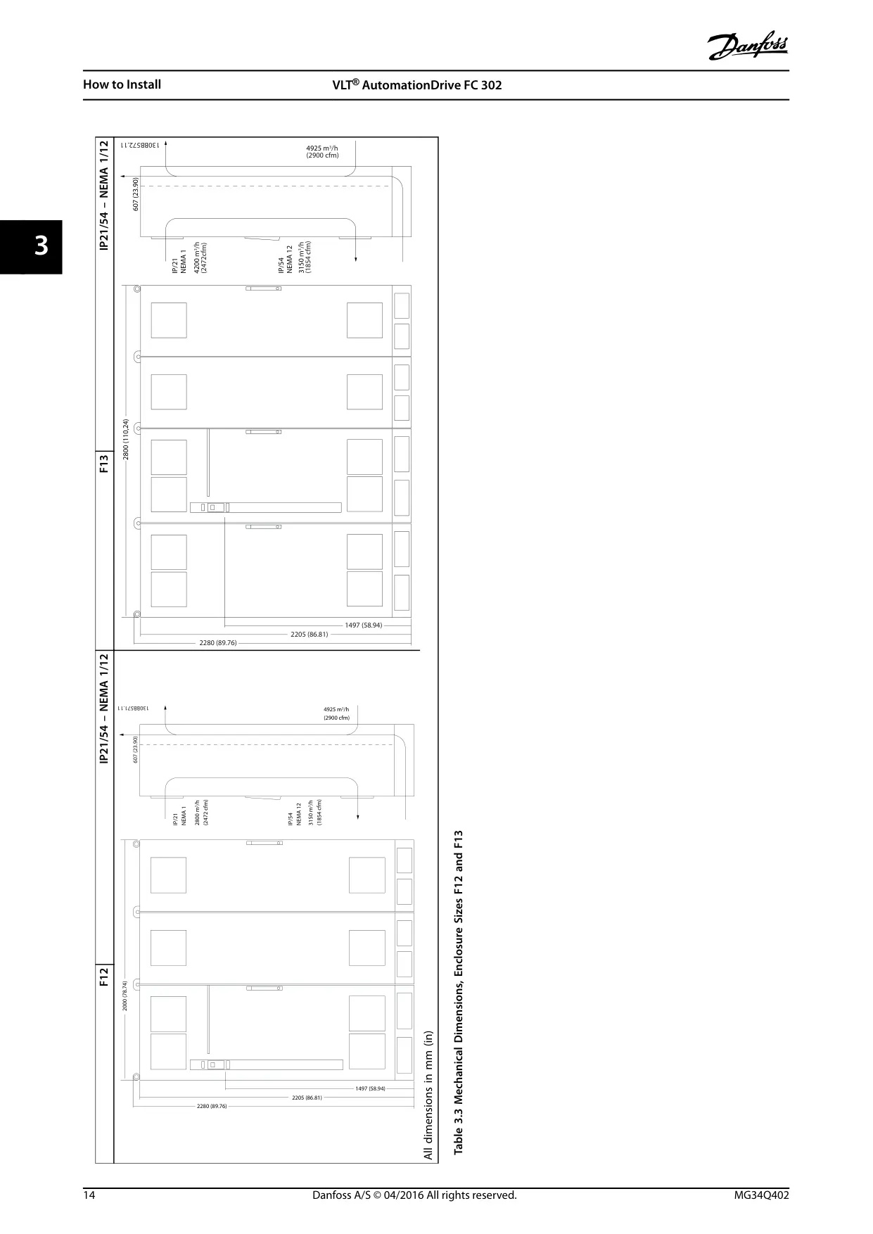
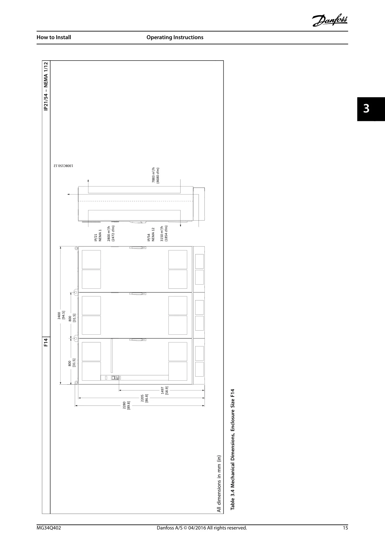
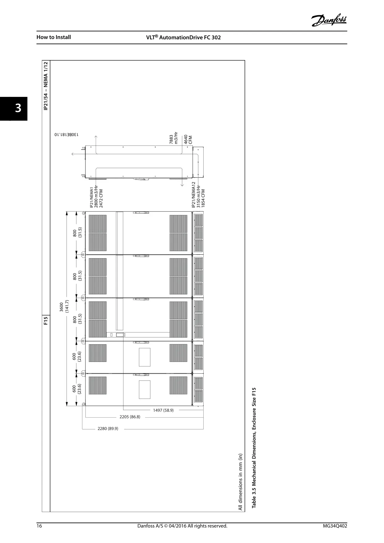
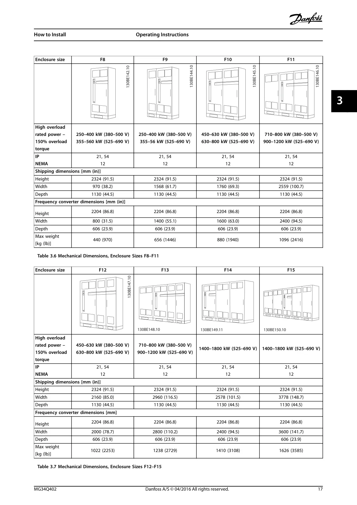
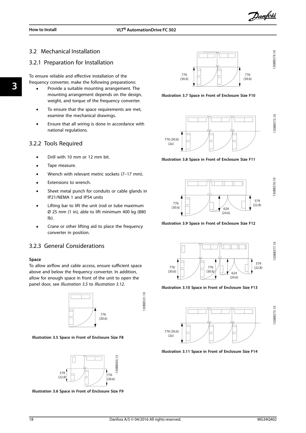
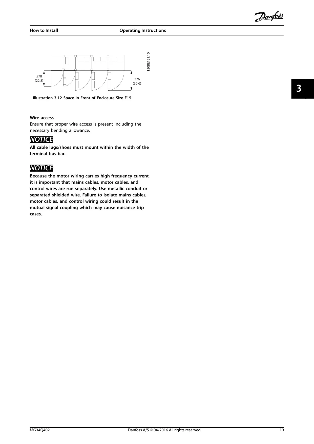
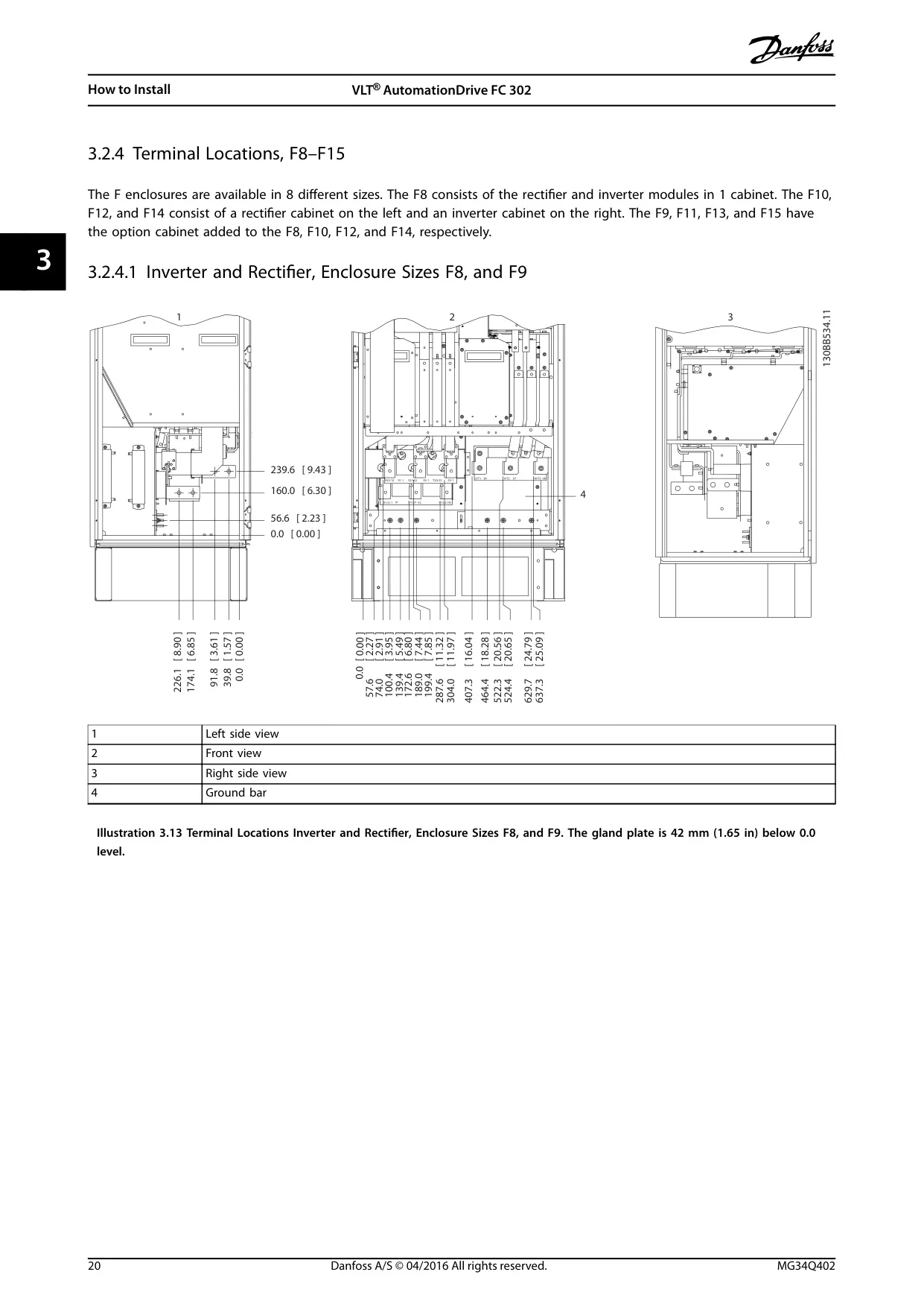
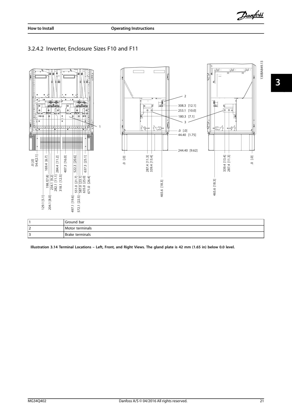
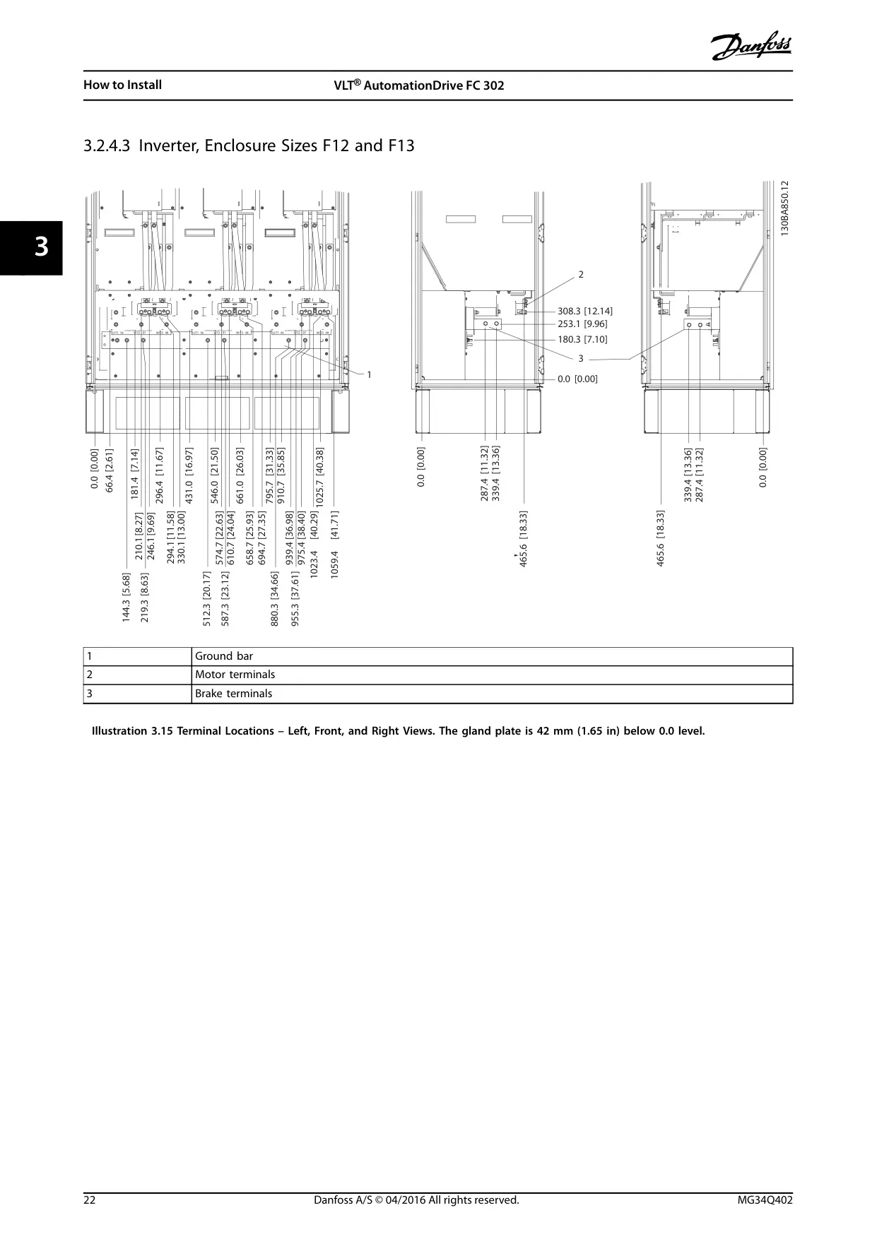
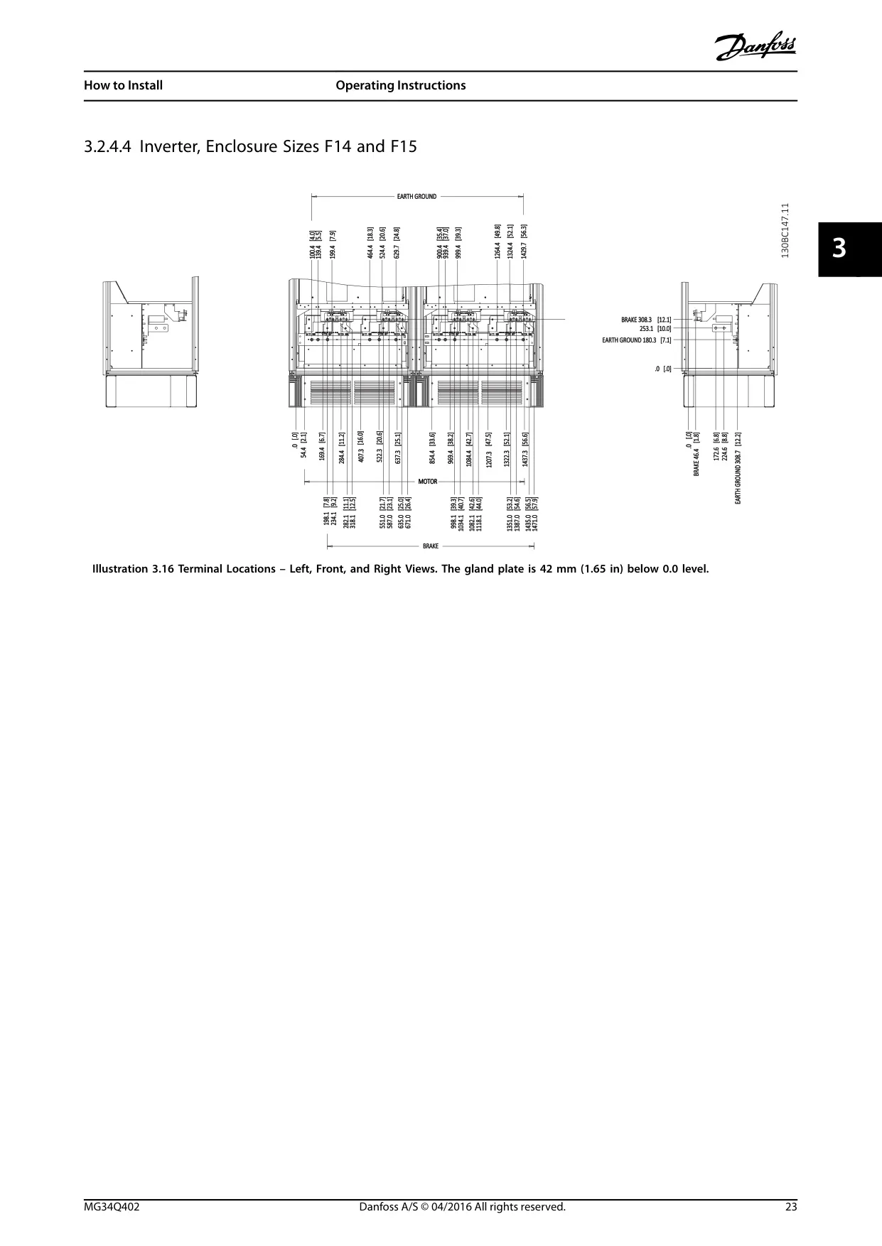
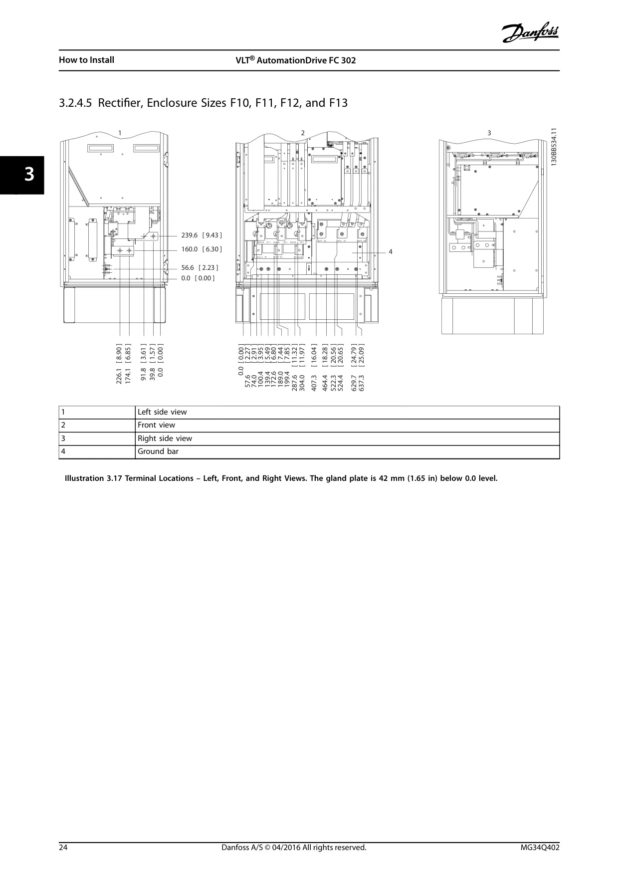
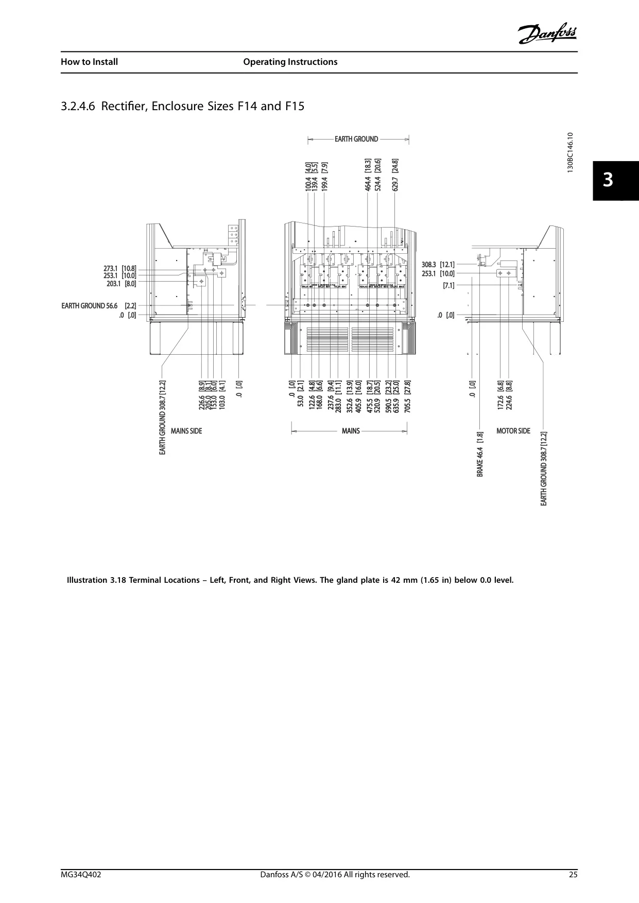
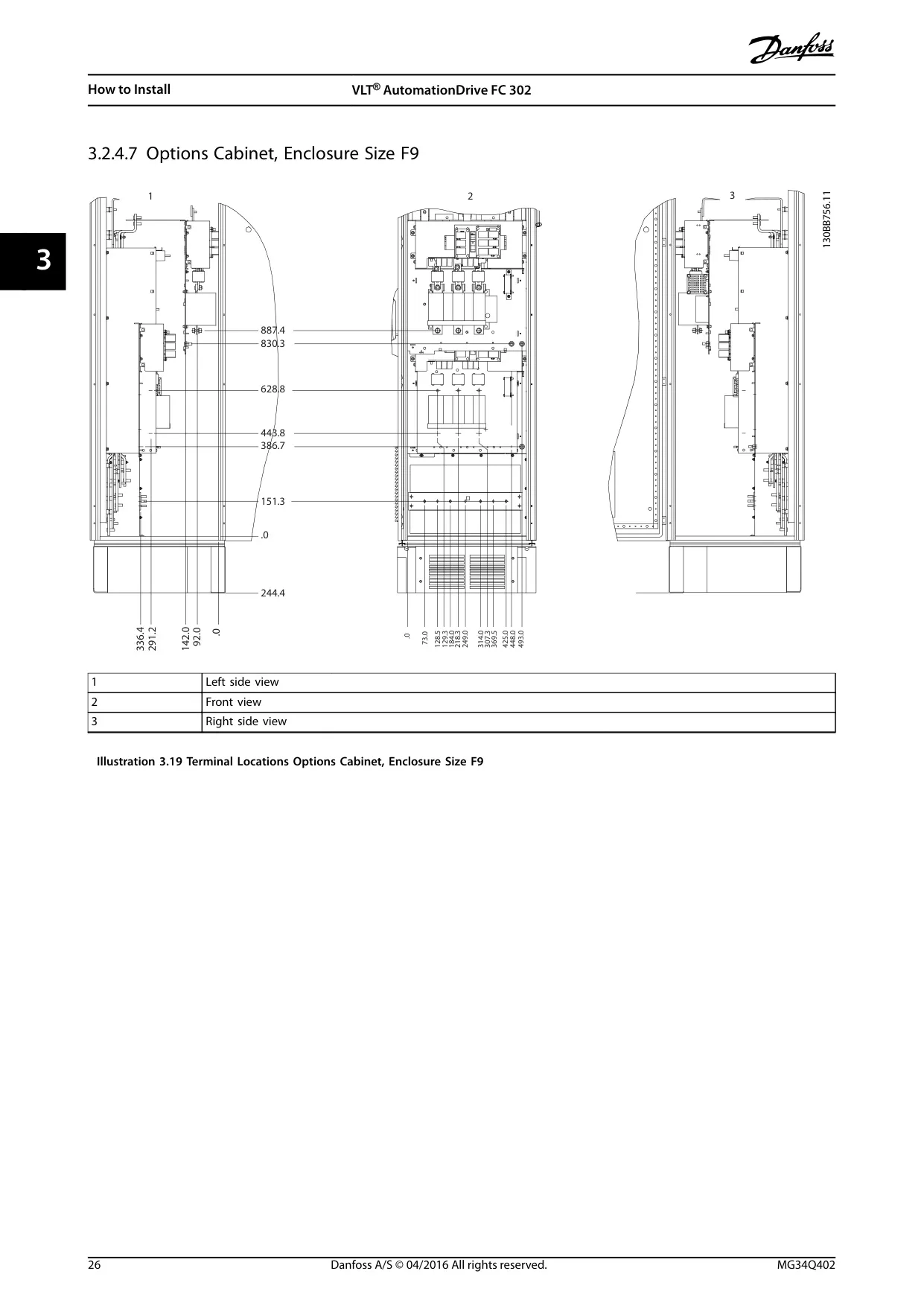
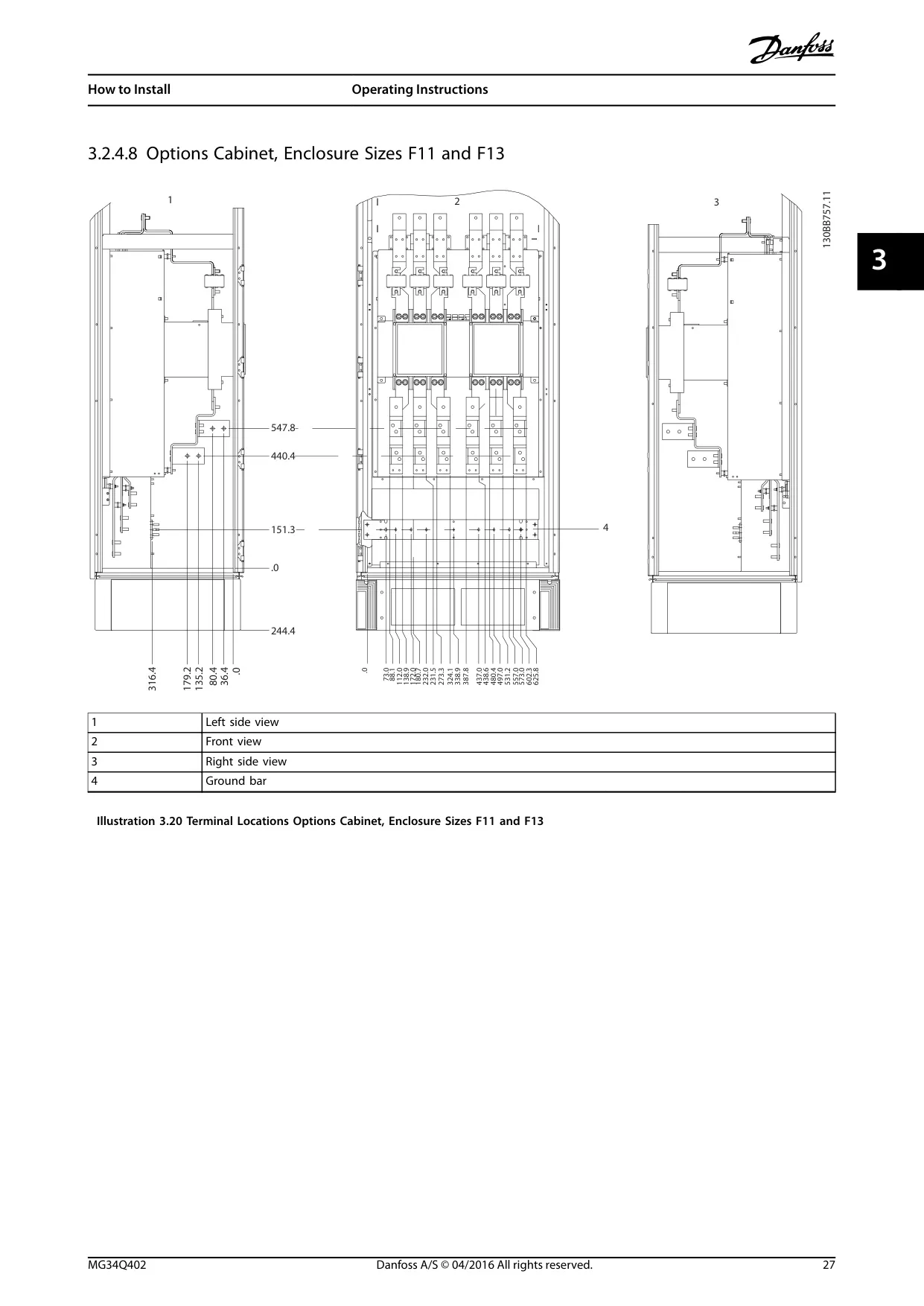
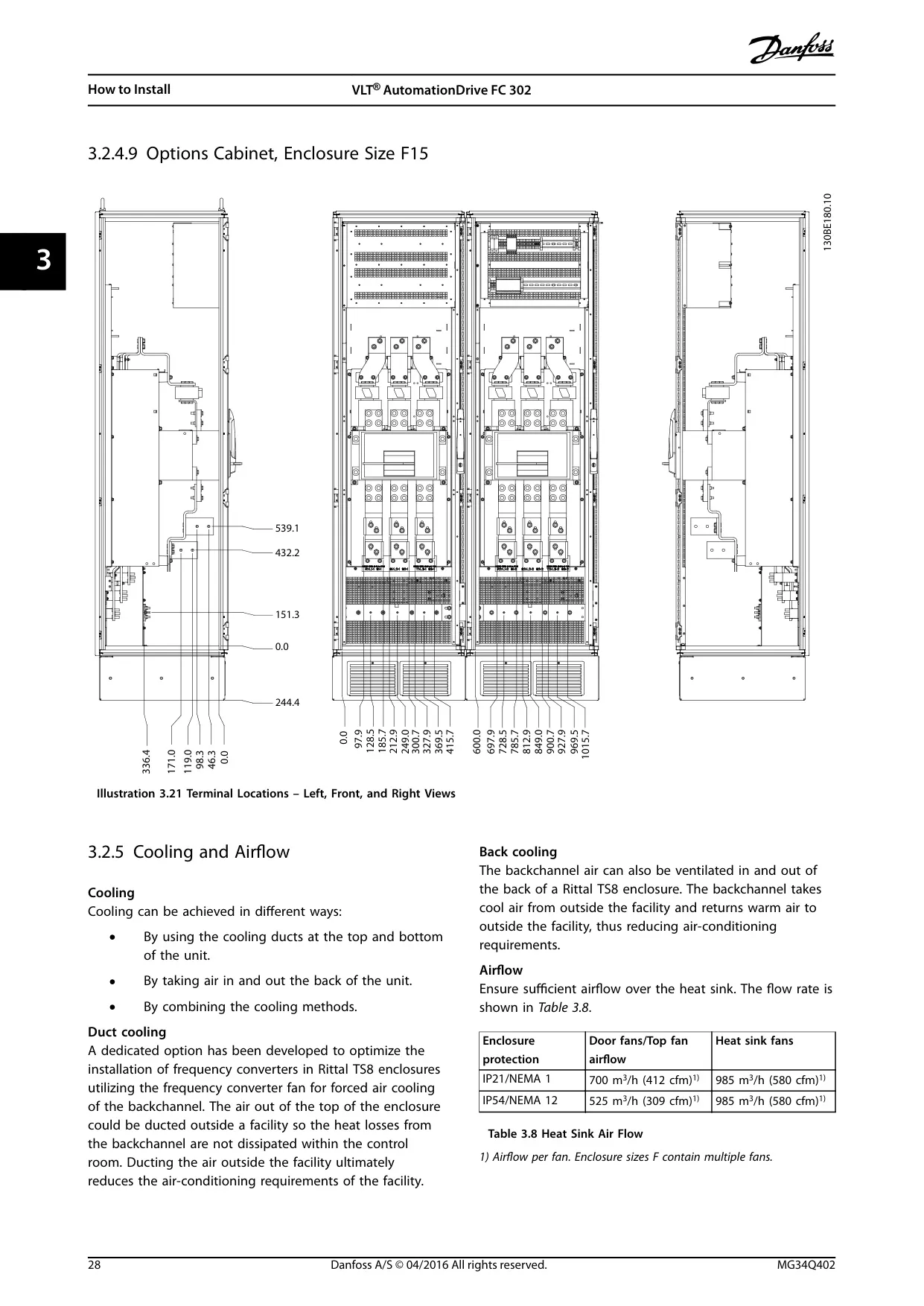
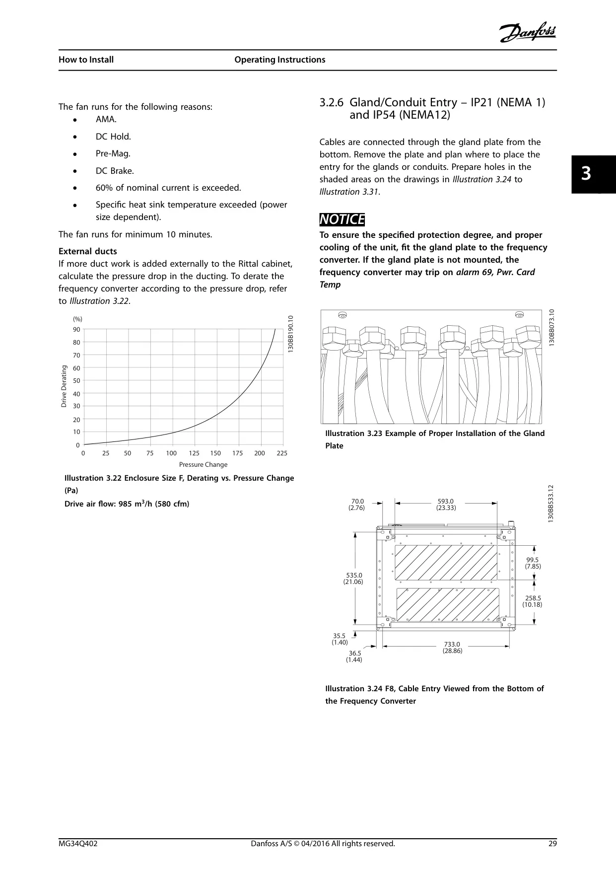
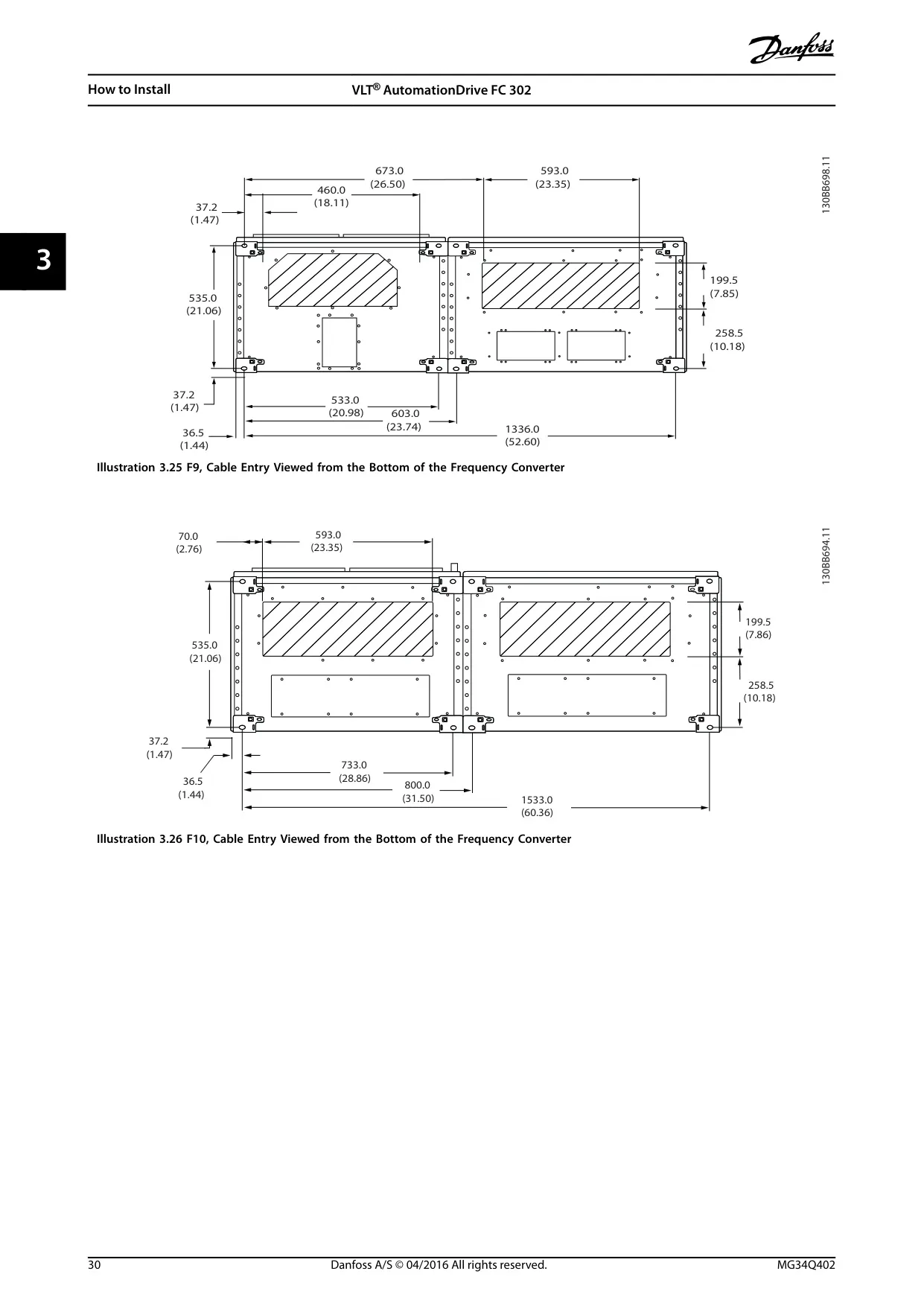
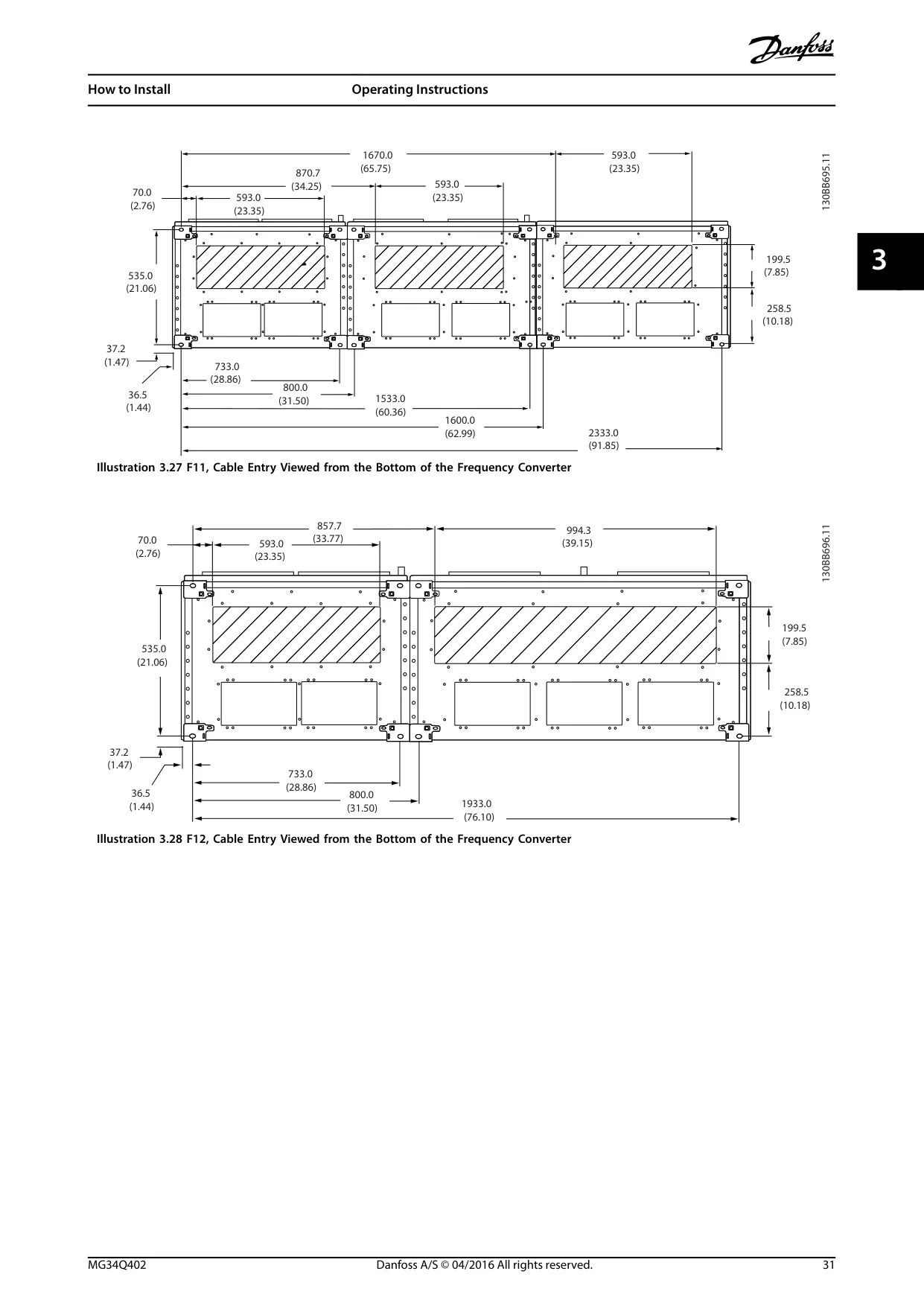
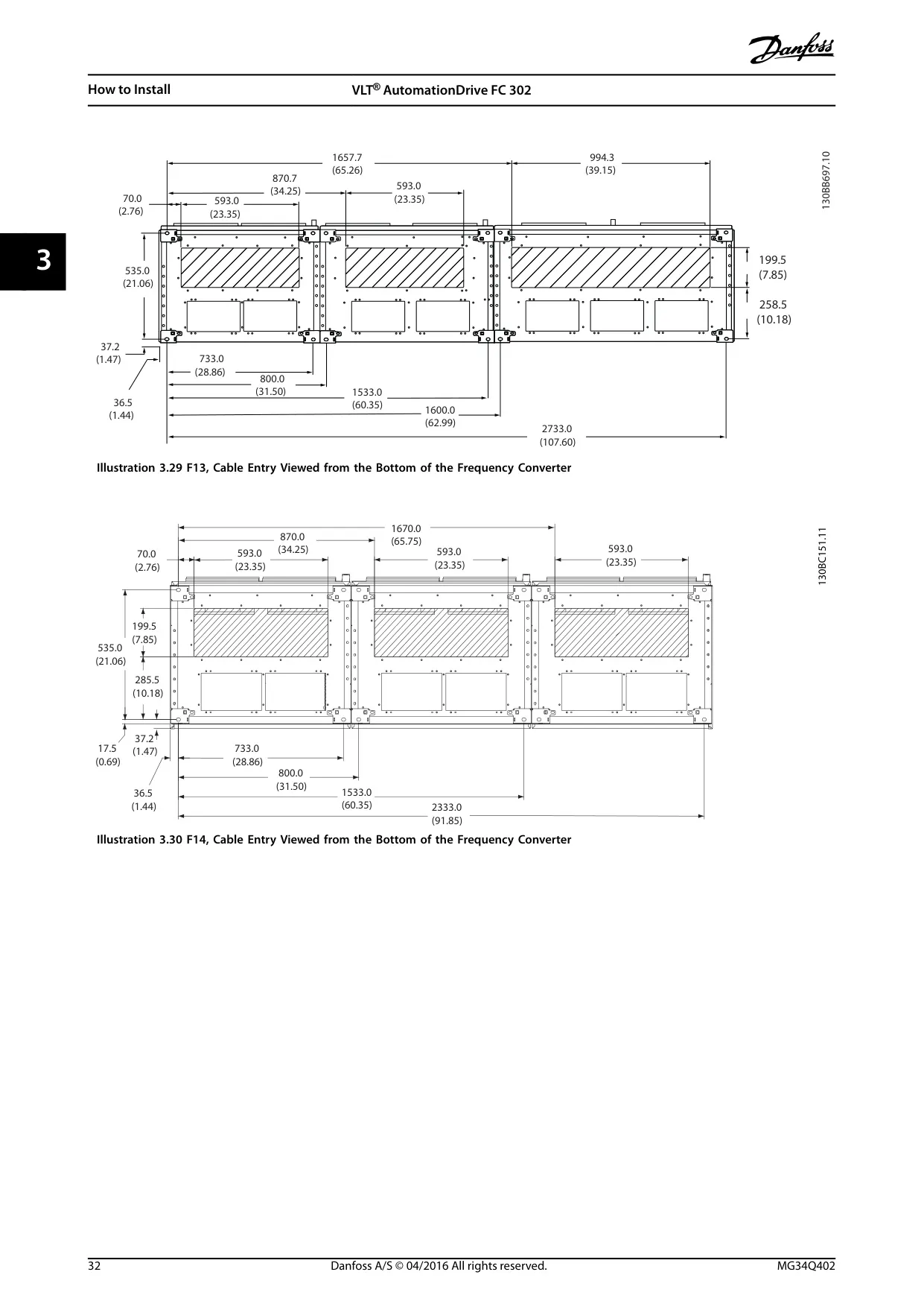
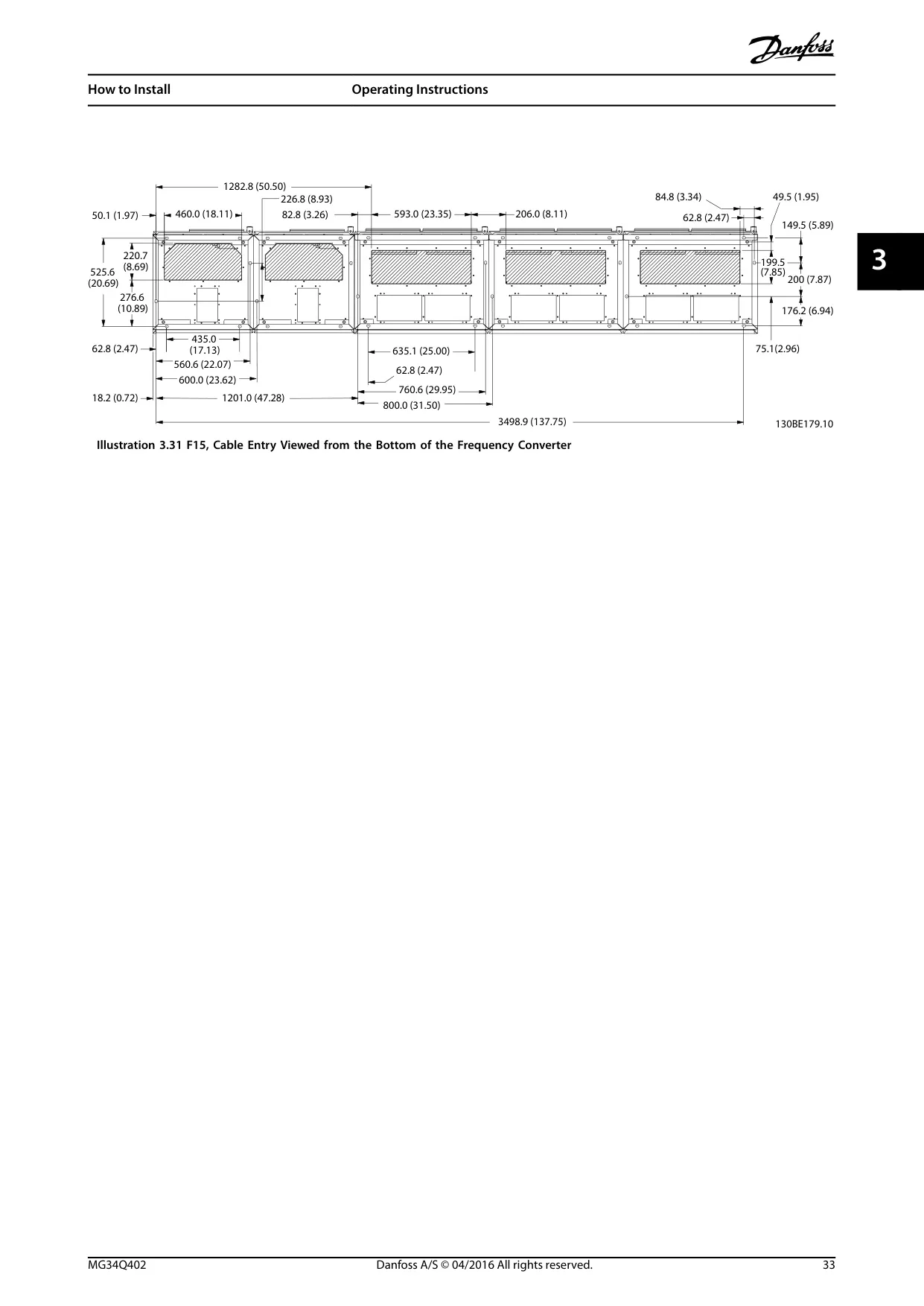
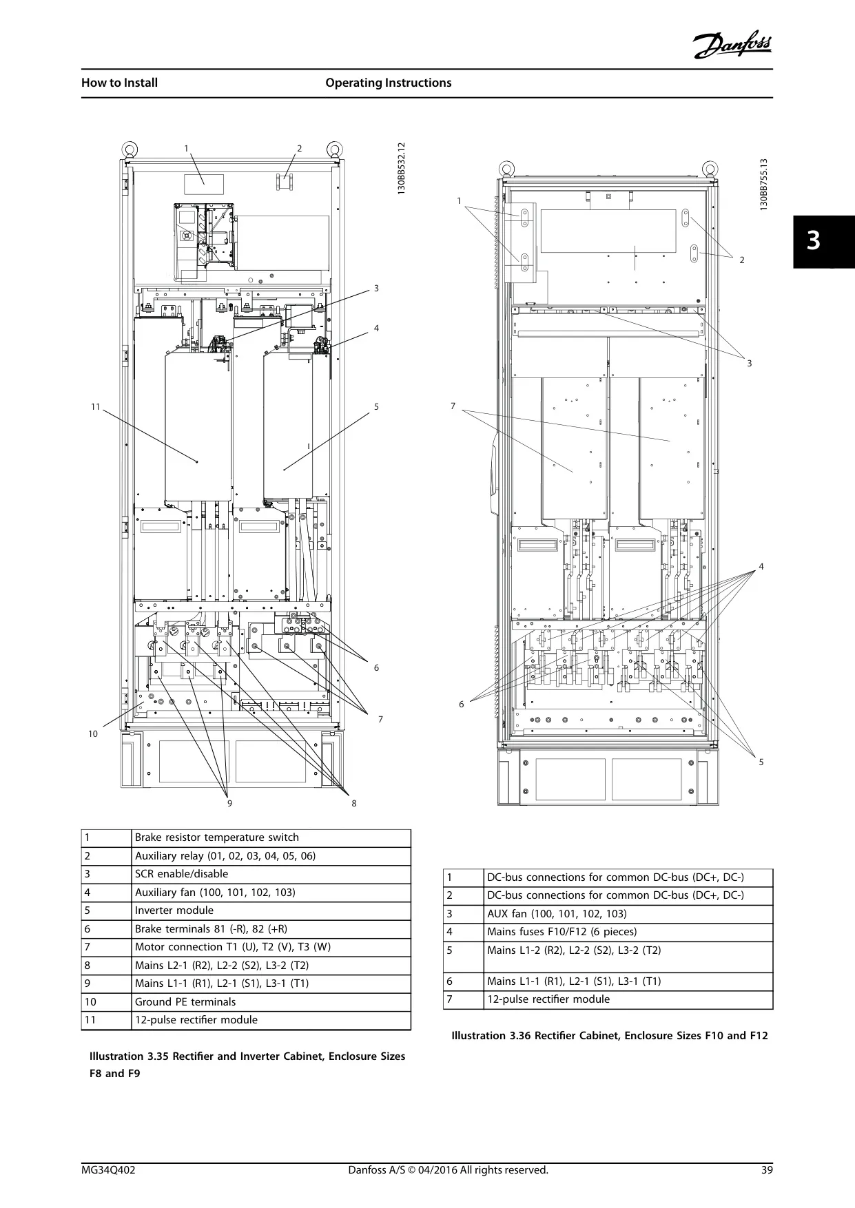
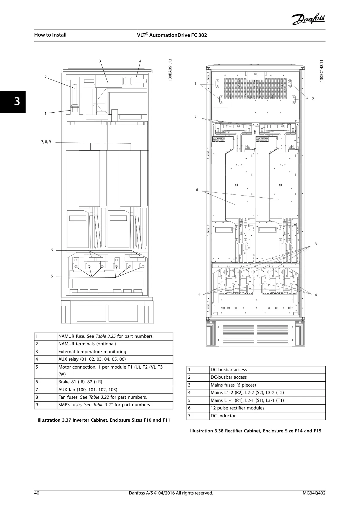
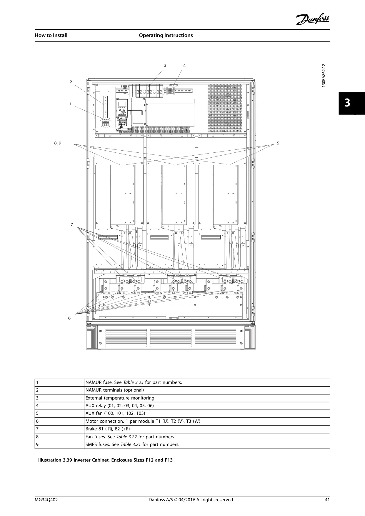
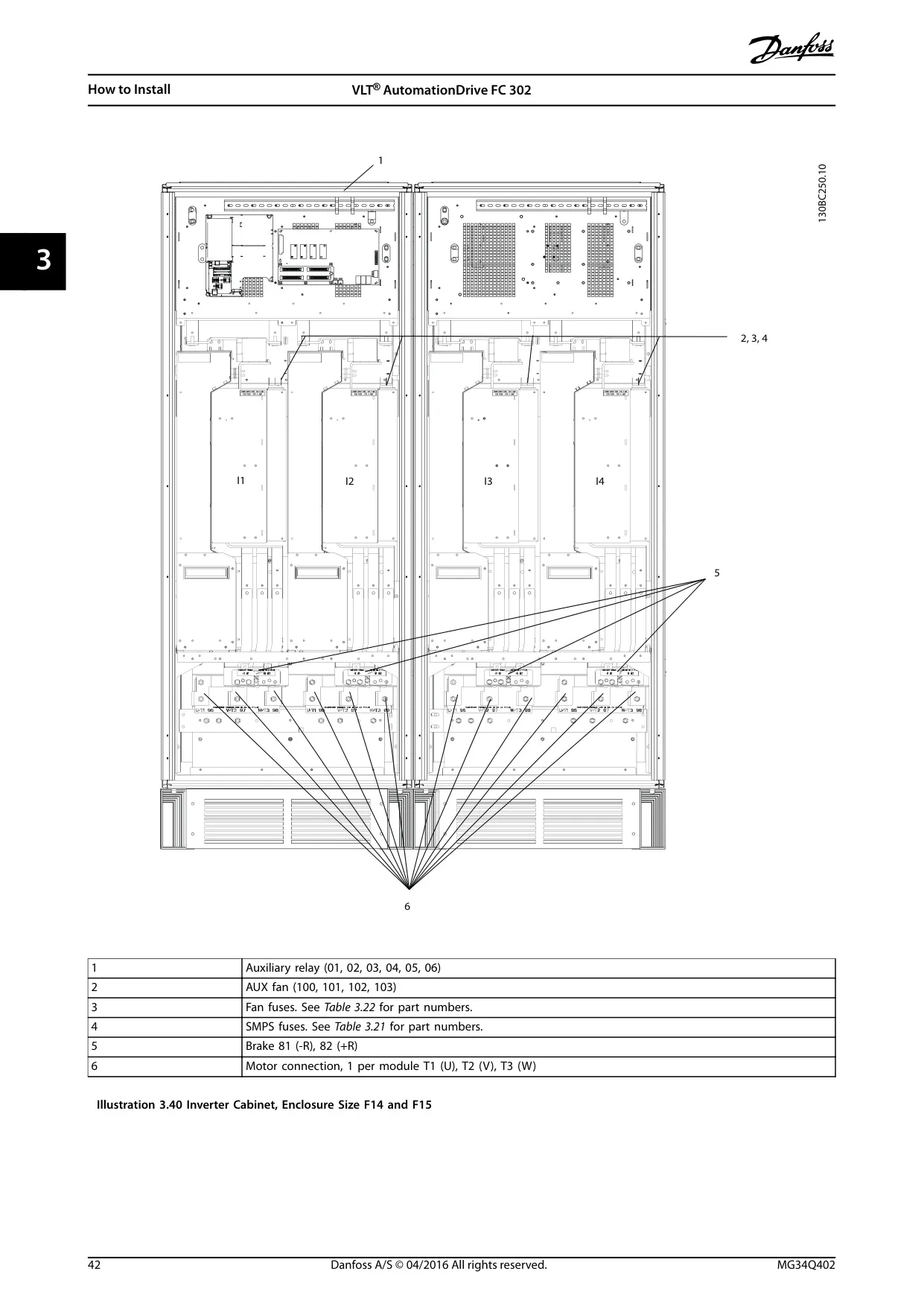
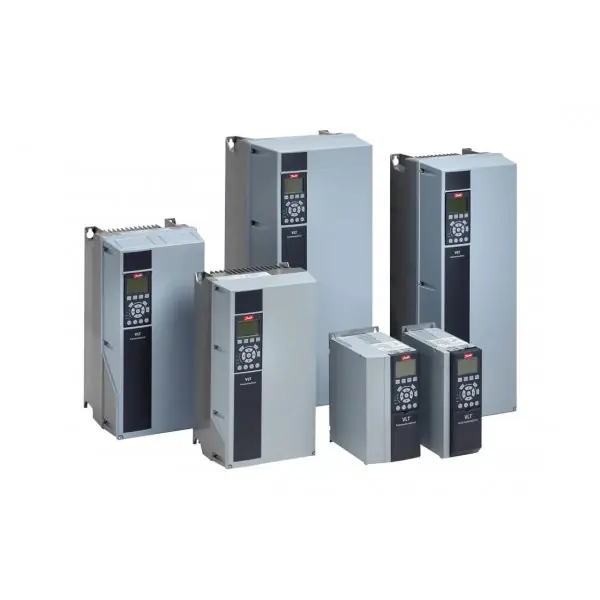
Mechanical installation planning is emphasized, considering ambient temperature, cooling methods, and proper unit positioning. The manual provides detailed instructions for lifting heavy units using dedicated lifting eyes and outlines precise mechanical dimensions for various enclosure sizes (F8–F15), facilitating optimal site preparation and space allocation for airflow and cable routing.
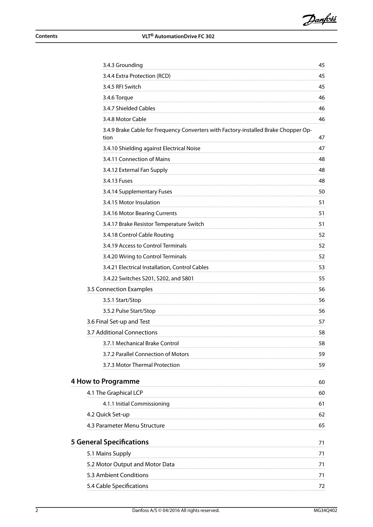
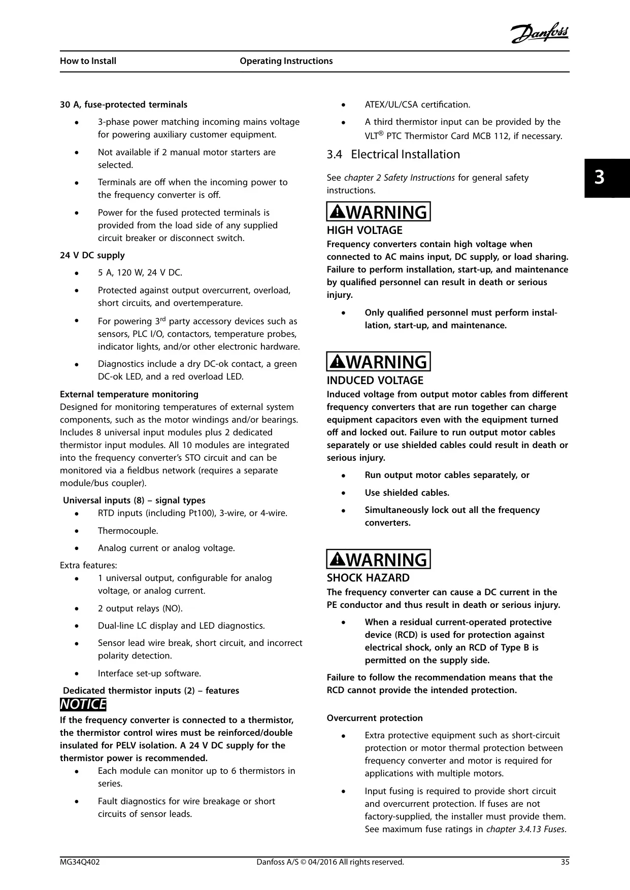
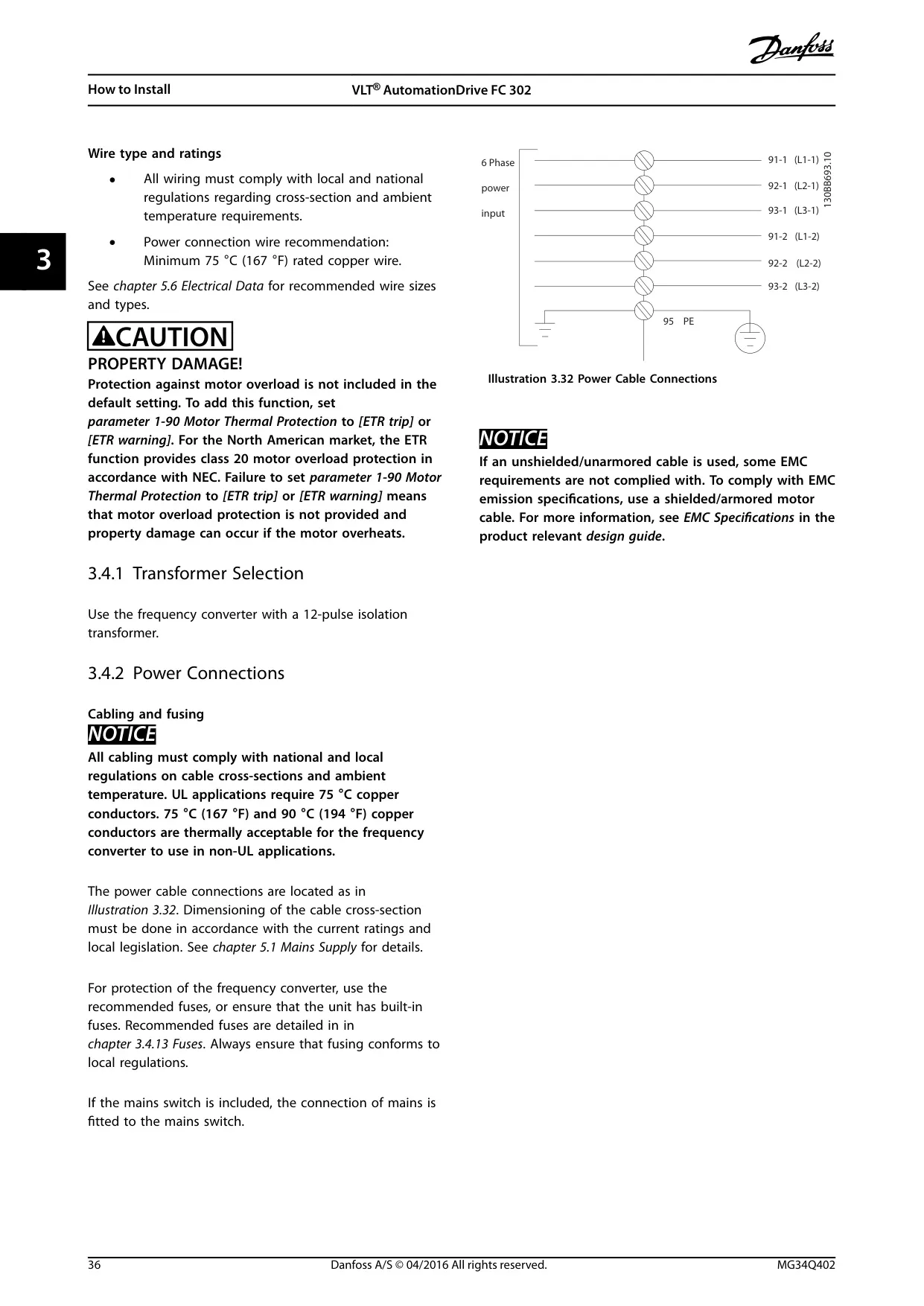
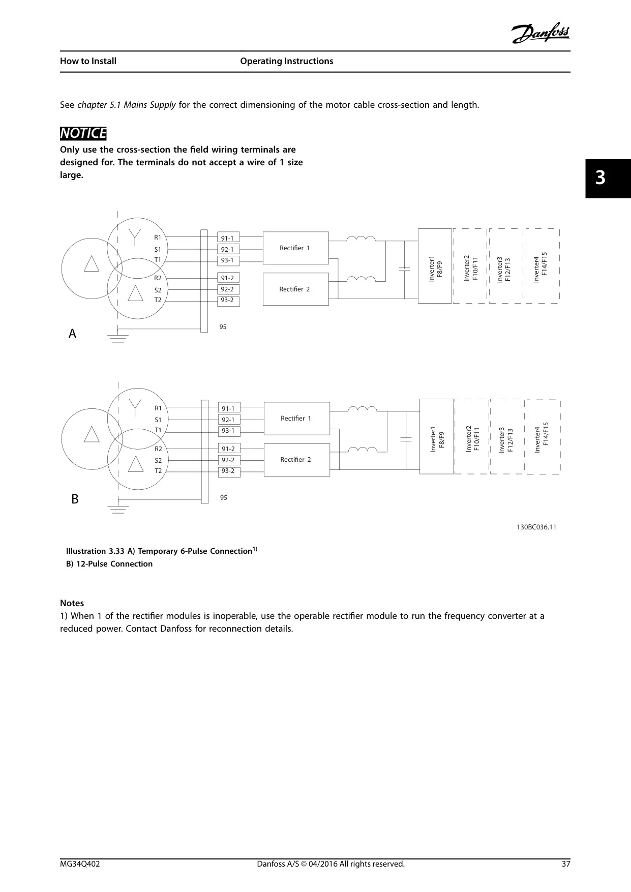
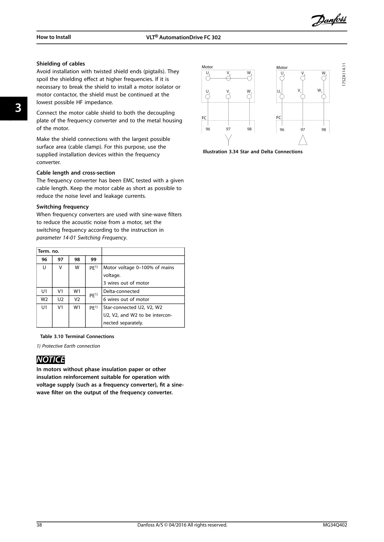
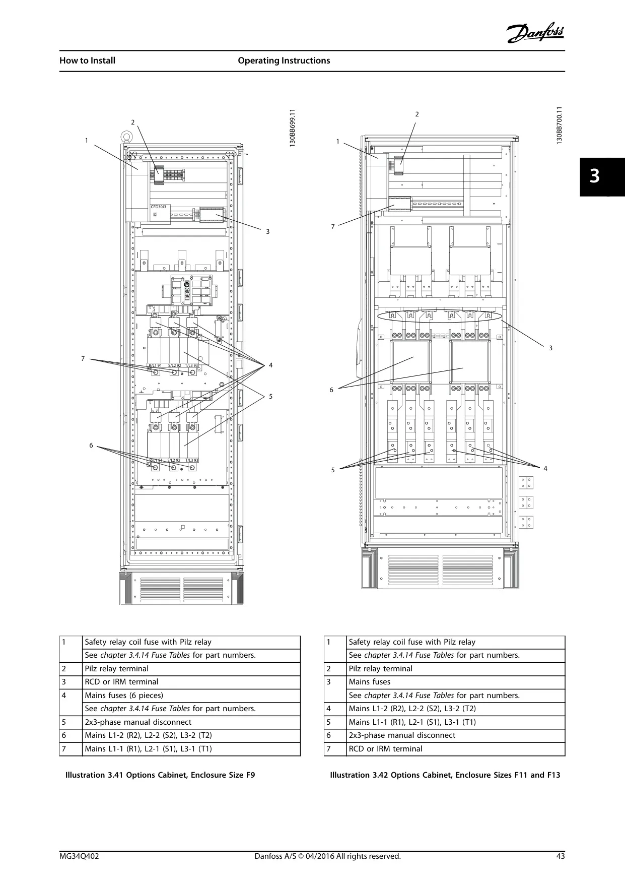
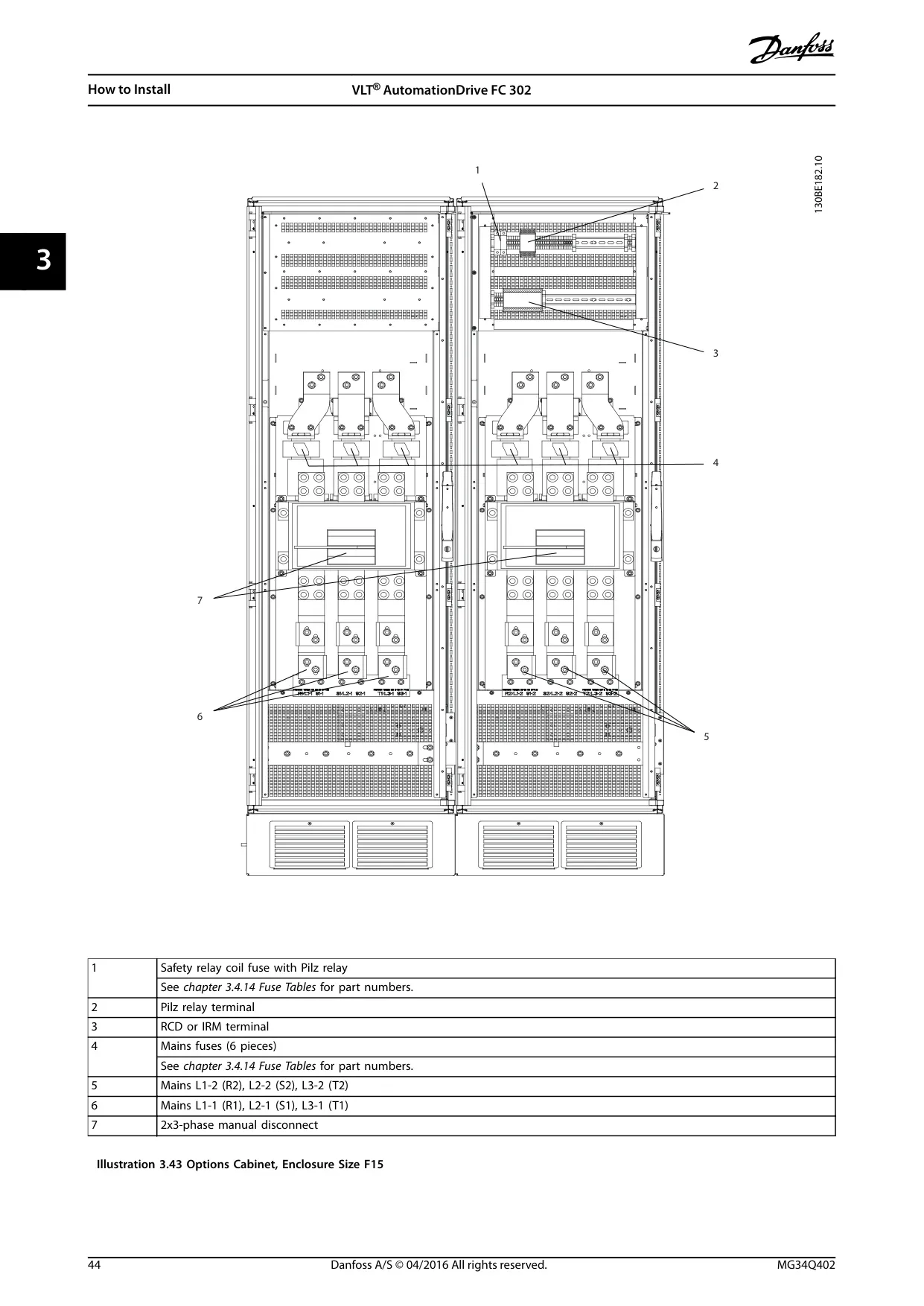
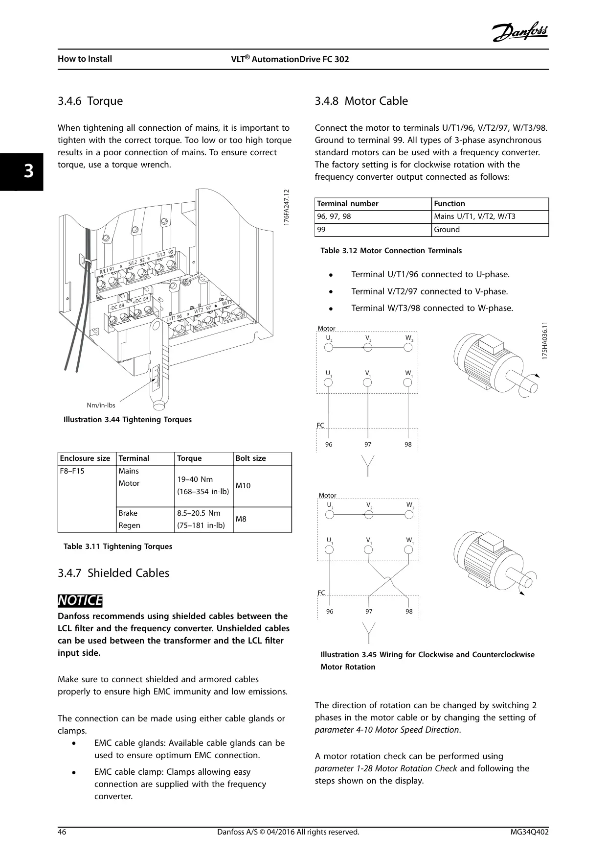
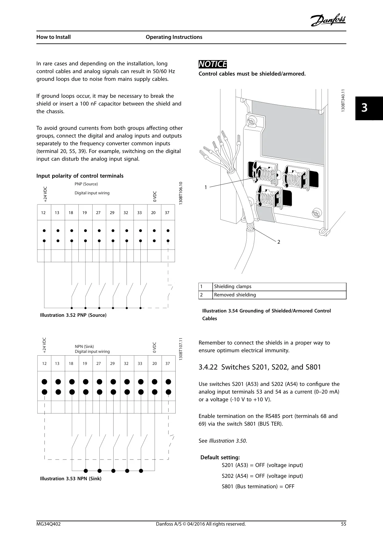
Electrical installation requires careful attention to grounding, power connections, and cable specifications. The FC-302 supports 12-pulse isolation transformers. It provides specific instructions for transformer selection, fuse requirements, and shielding against electrical noise. Proper wire access and isolation of mains, motor, and control cables are critical for EMC compliance and preventing nuisance trips.
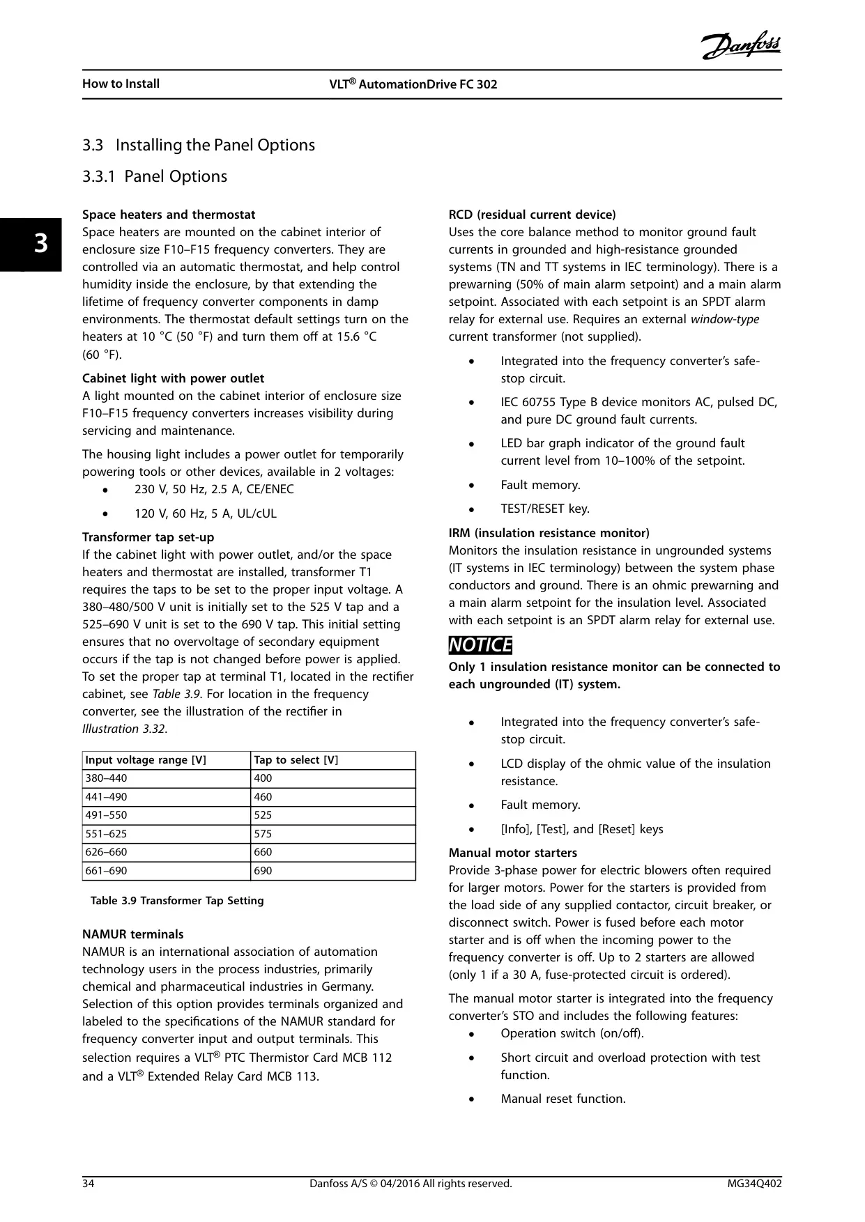
The drive offers various panel options to enhance functionality and reliability. These include space heaters and thermostats for humidity control, cabinet lights with power outlets for improved visibility, and specialized modules like NAMUR terminals, Residual Current Devices (RCD), and Insulation Resistance Monitors (IRM) for advanced protection and monitoring in specific industrial environments.
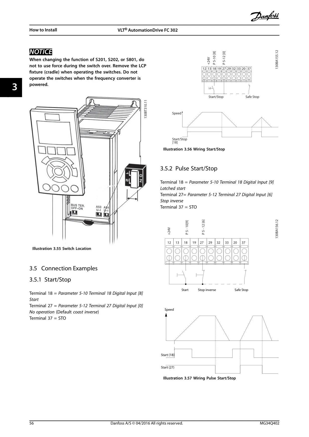
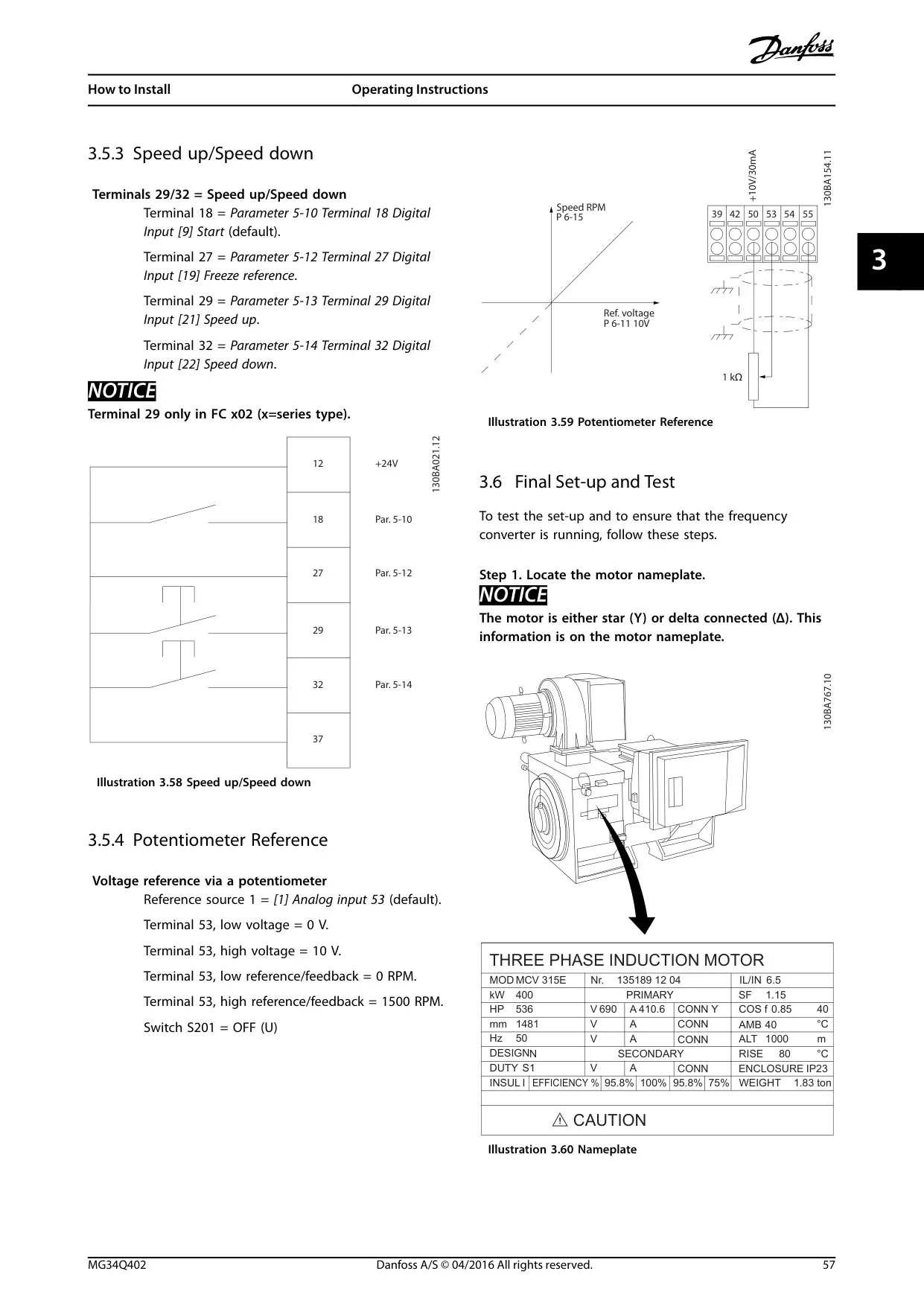
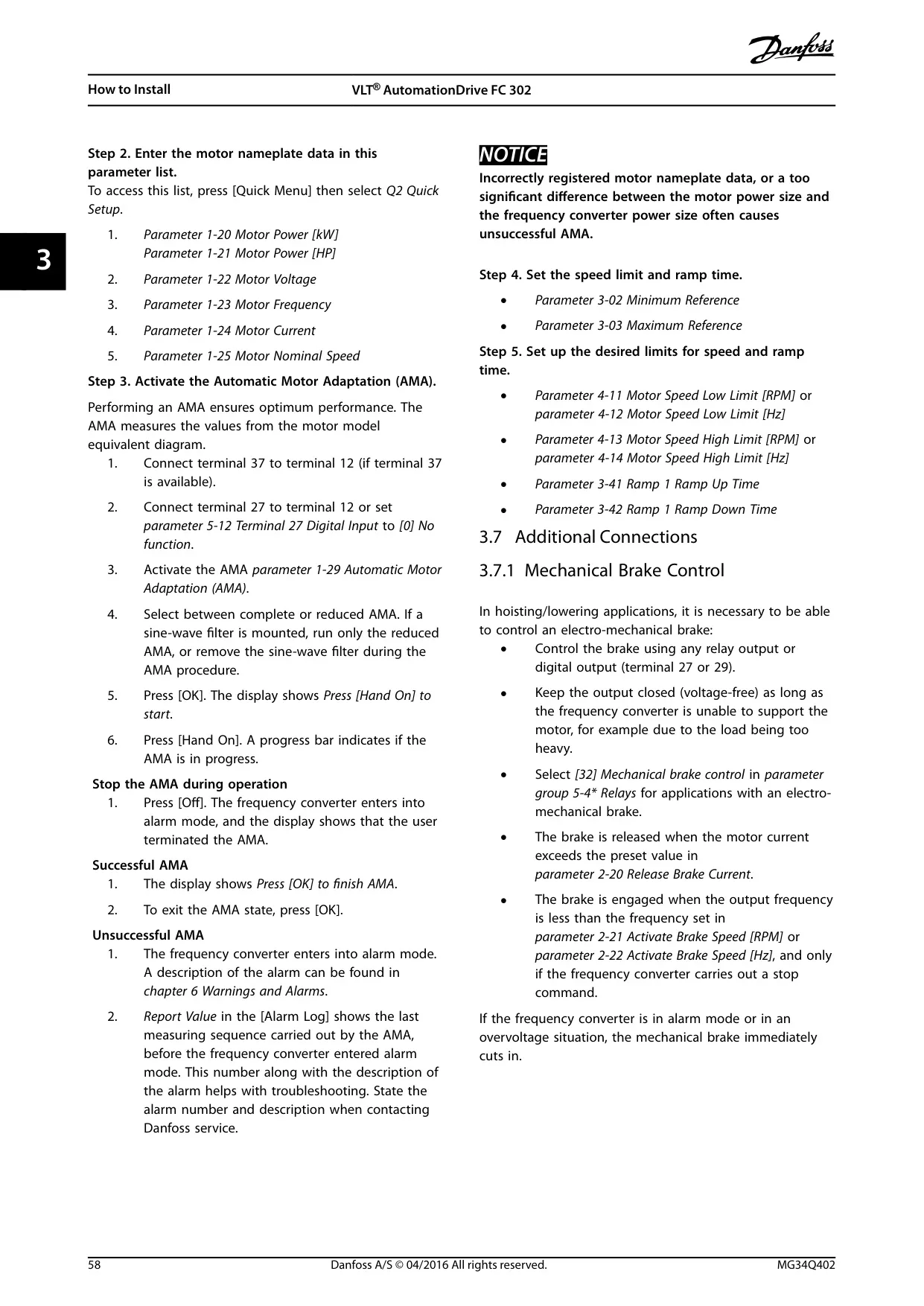
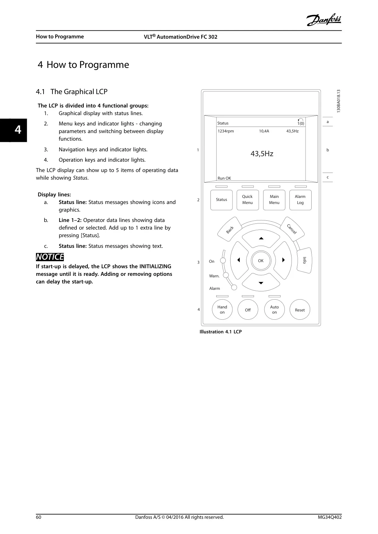
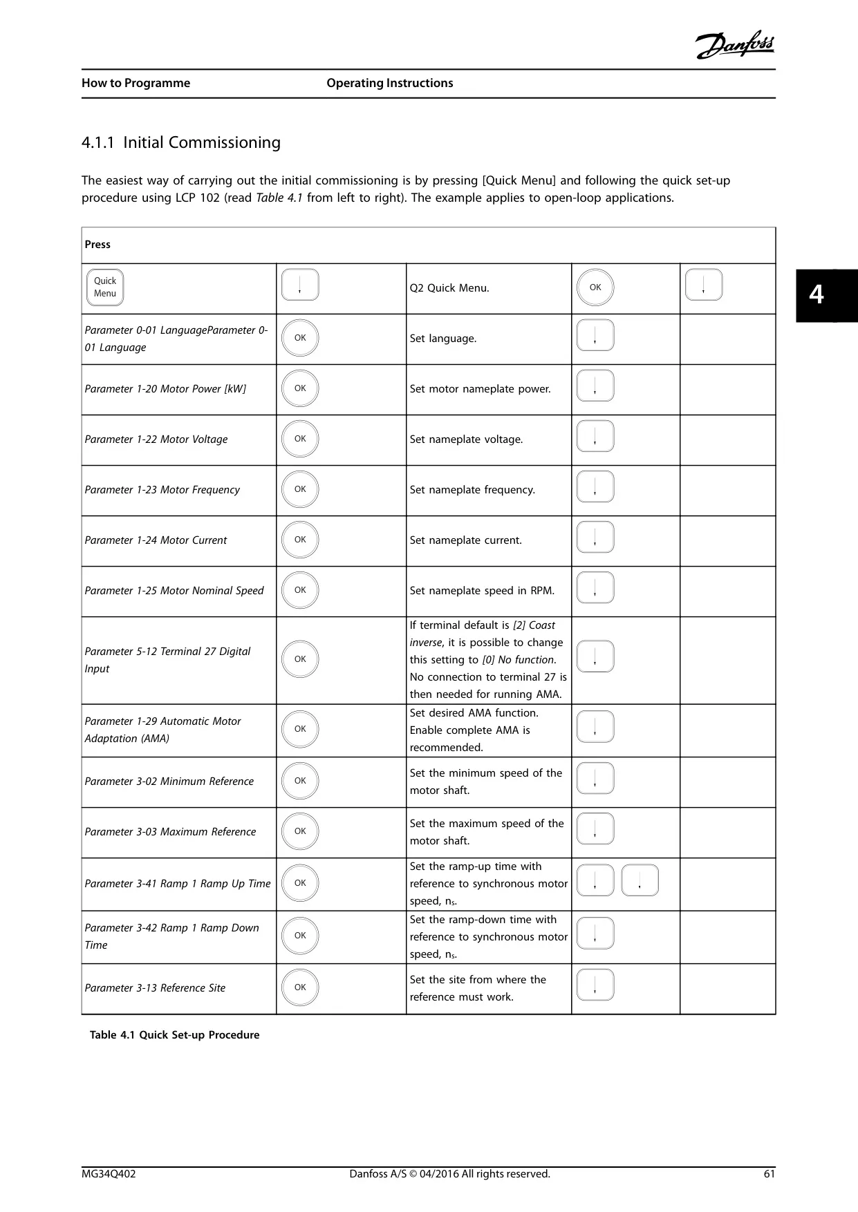
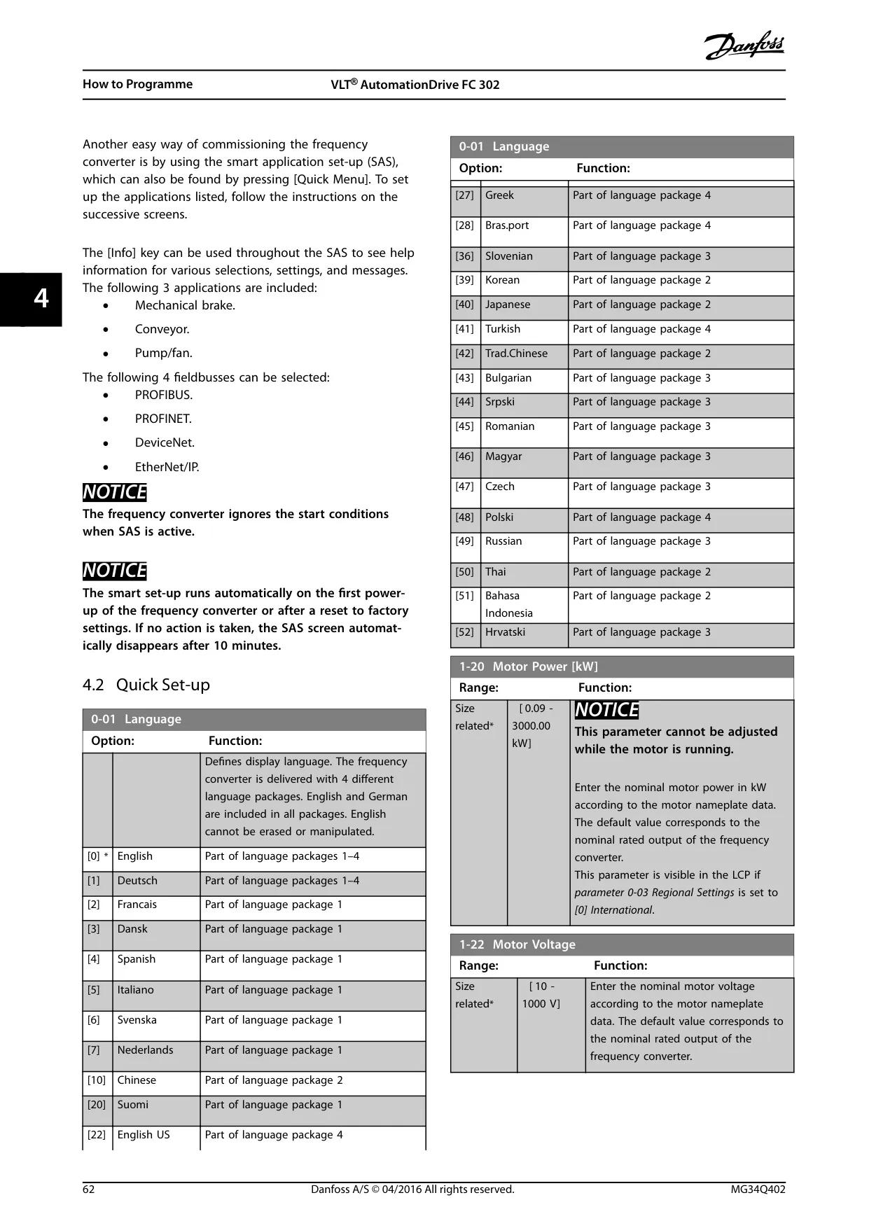
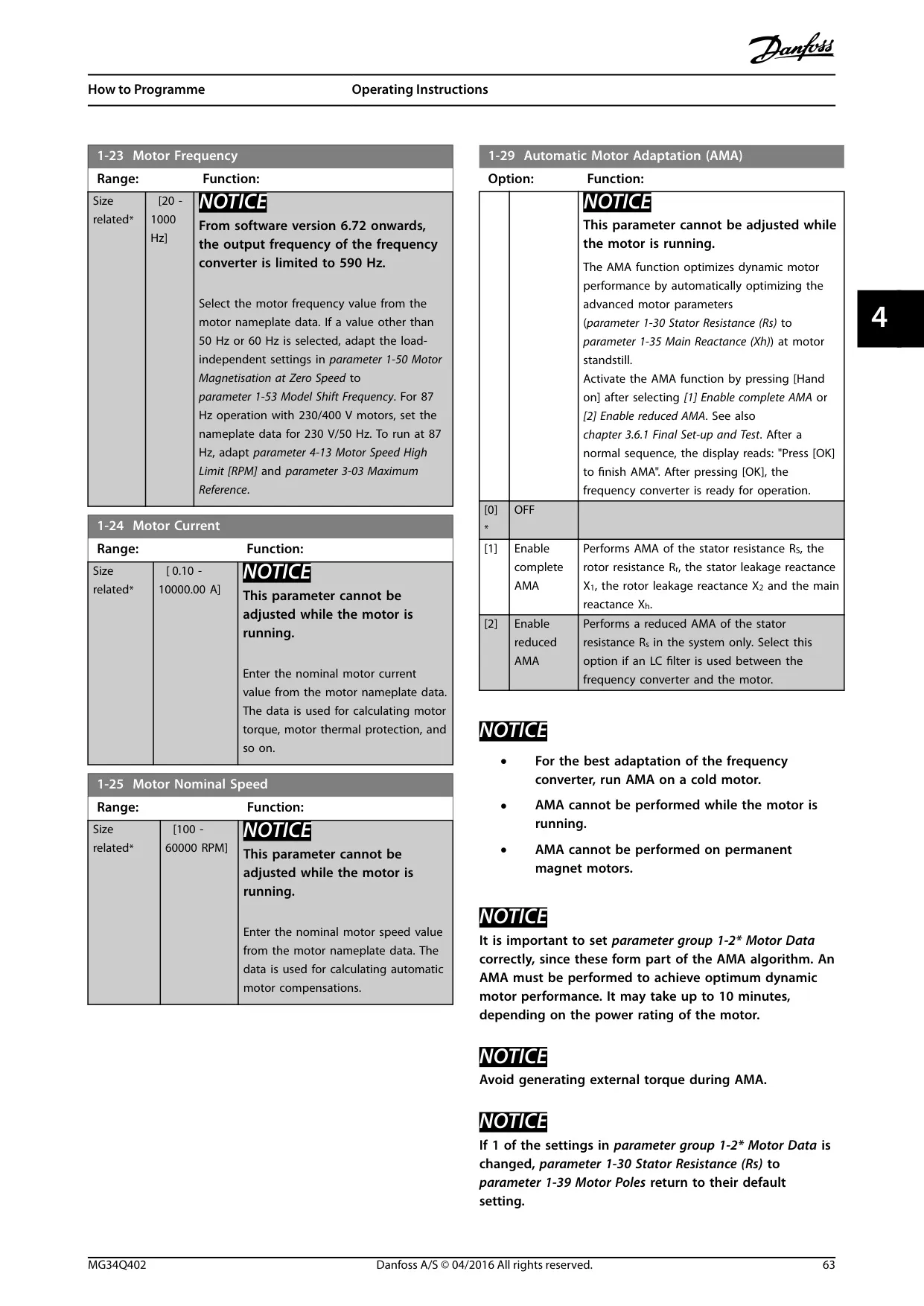
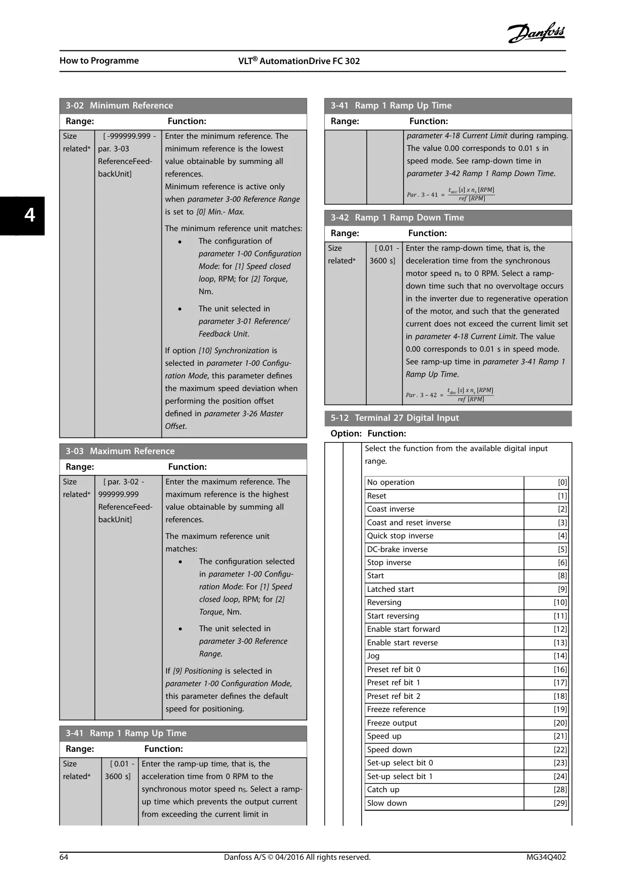
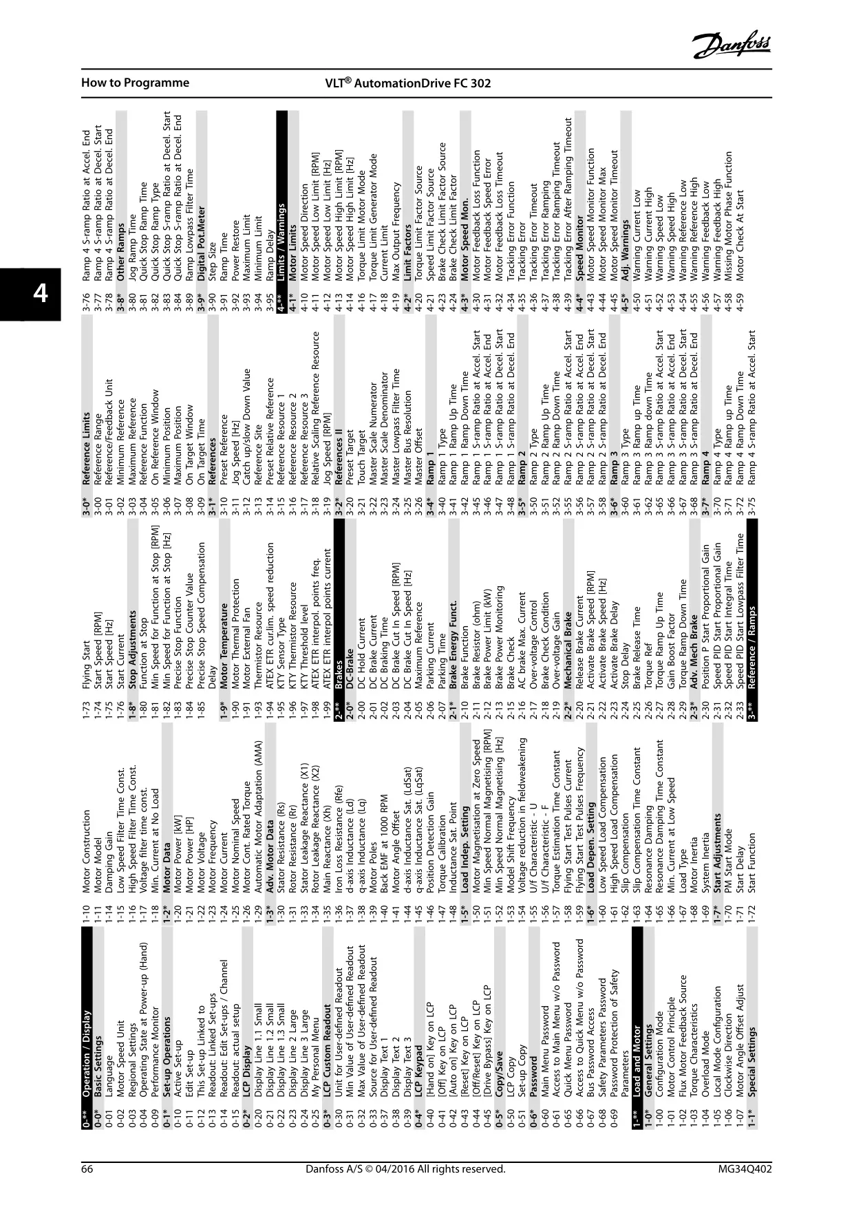
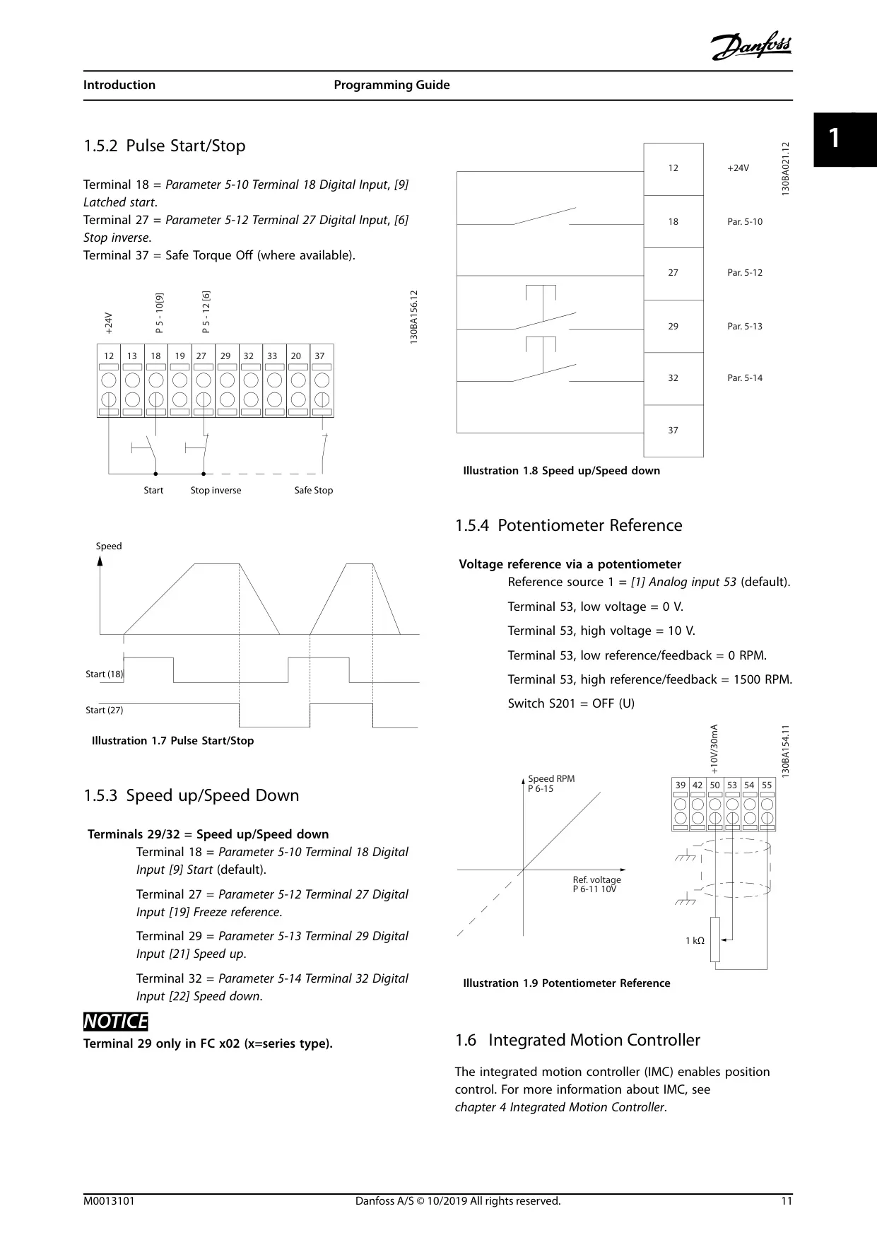
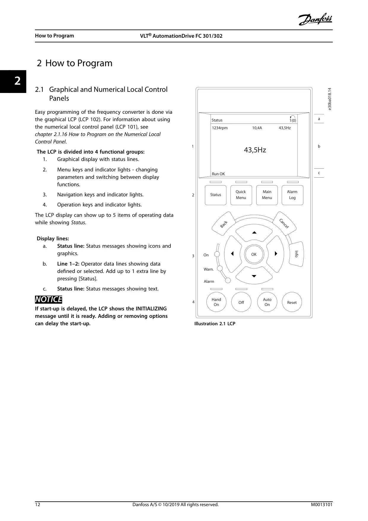
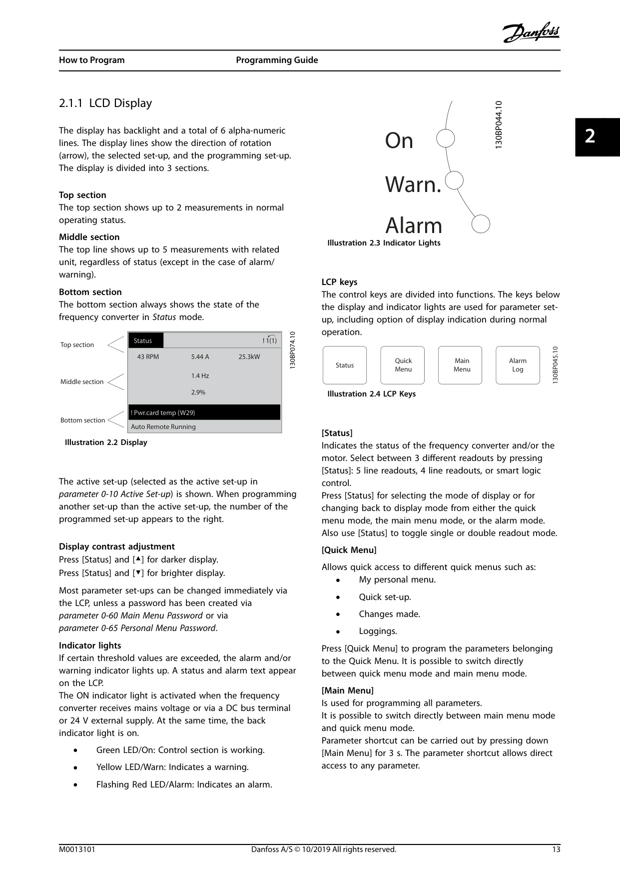
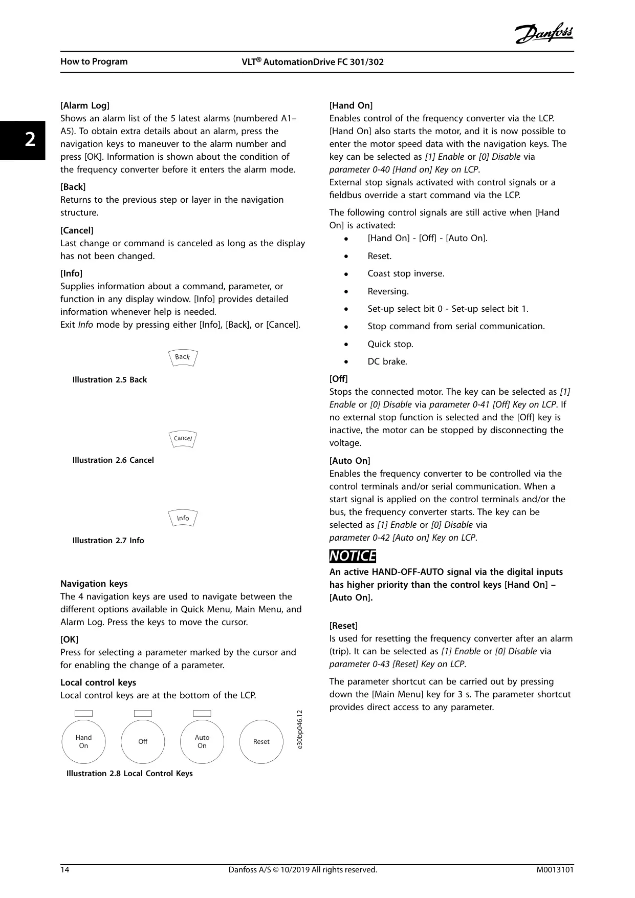
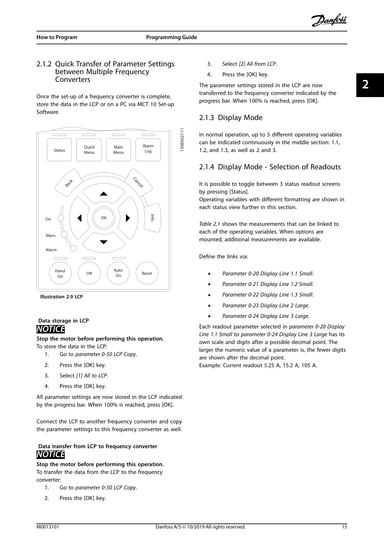
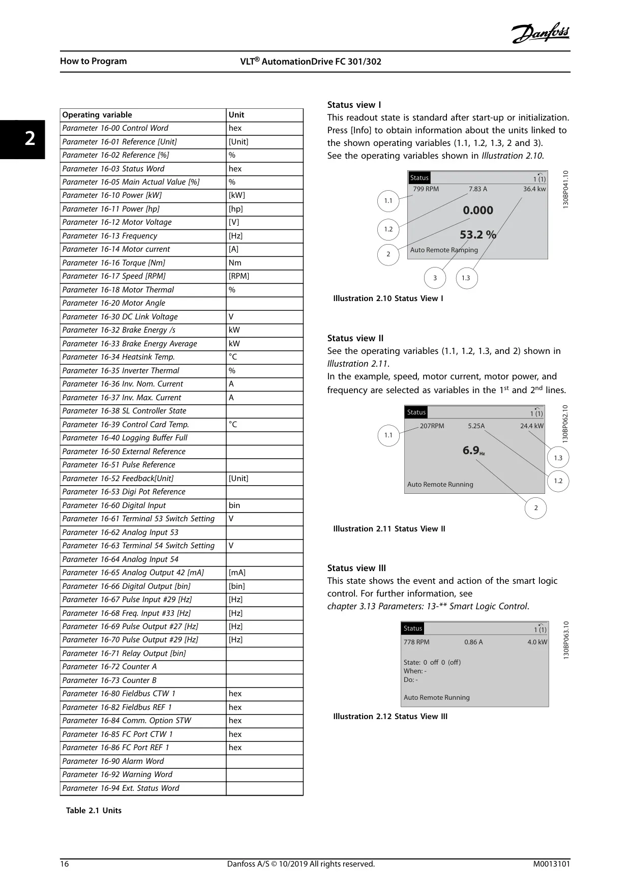
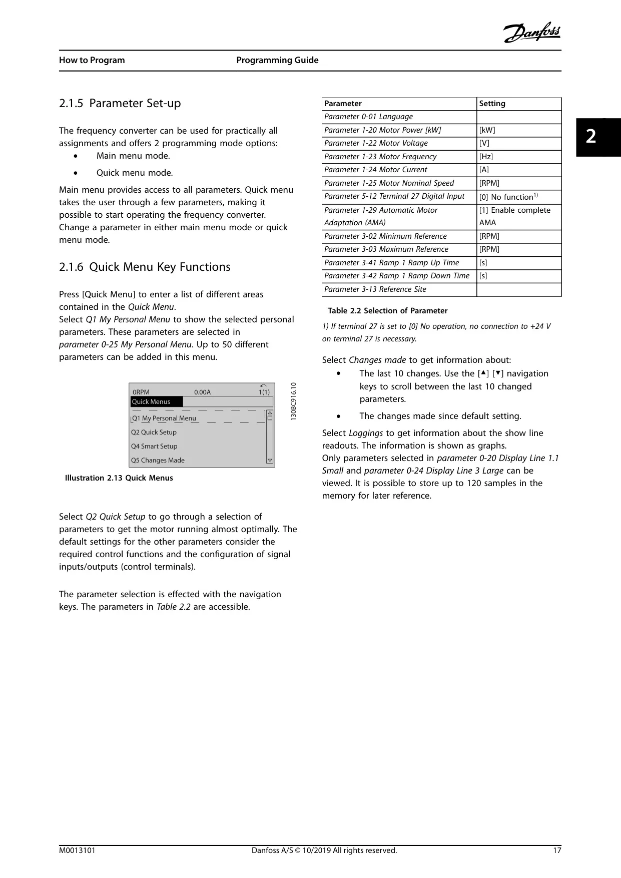
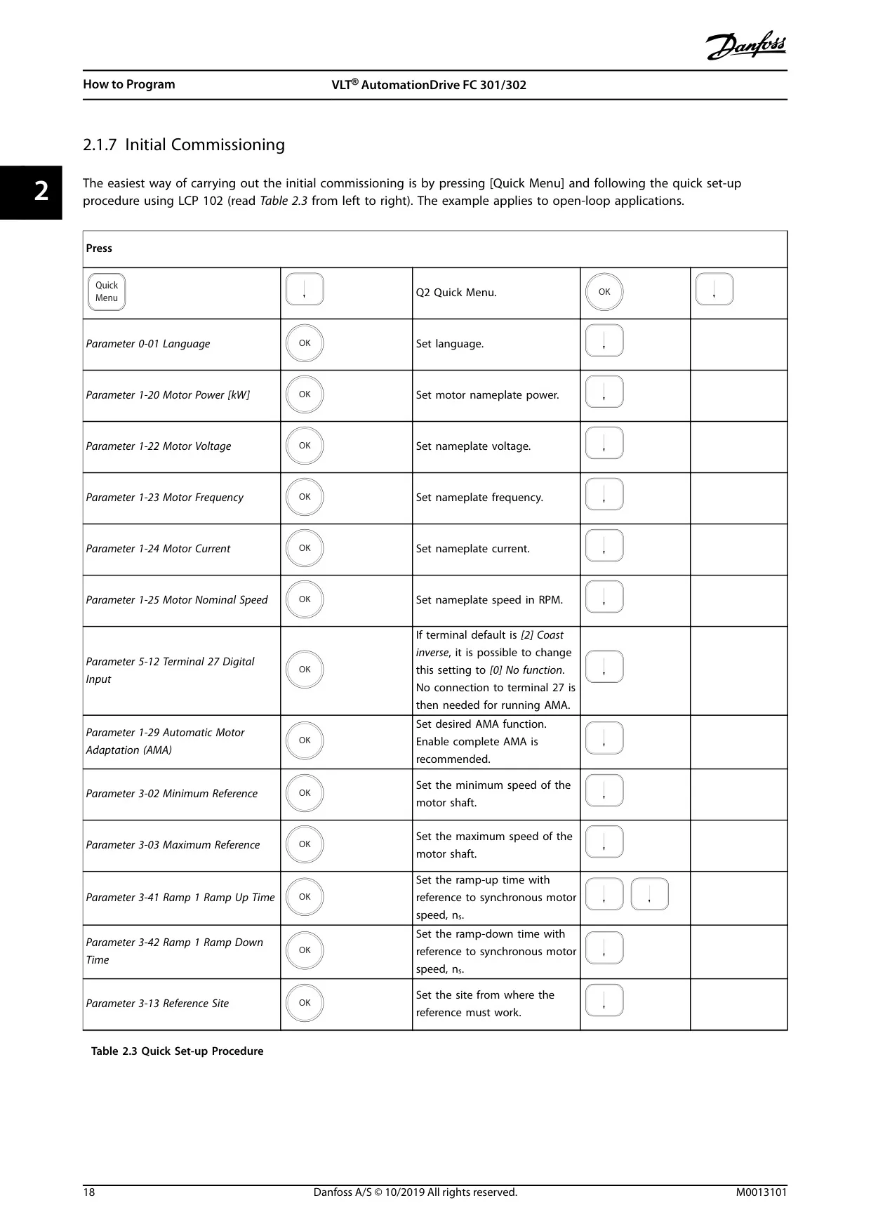
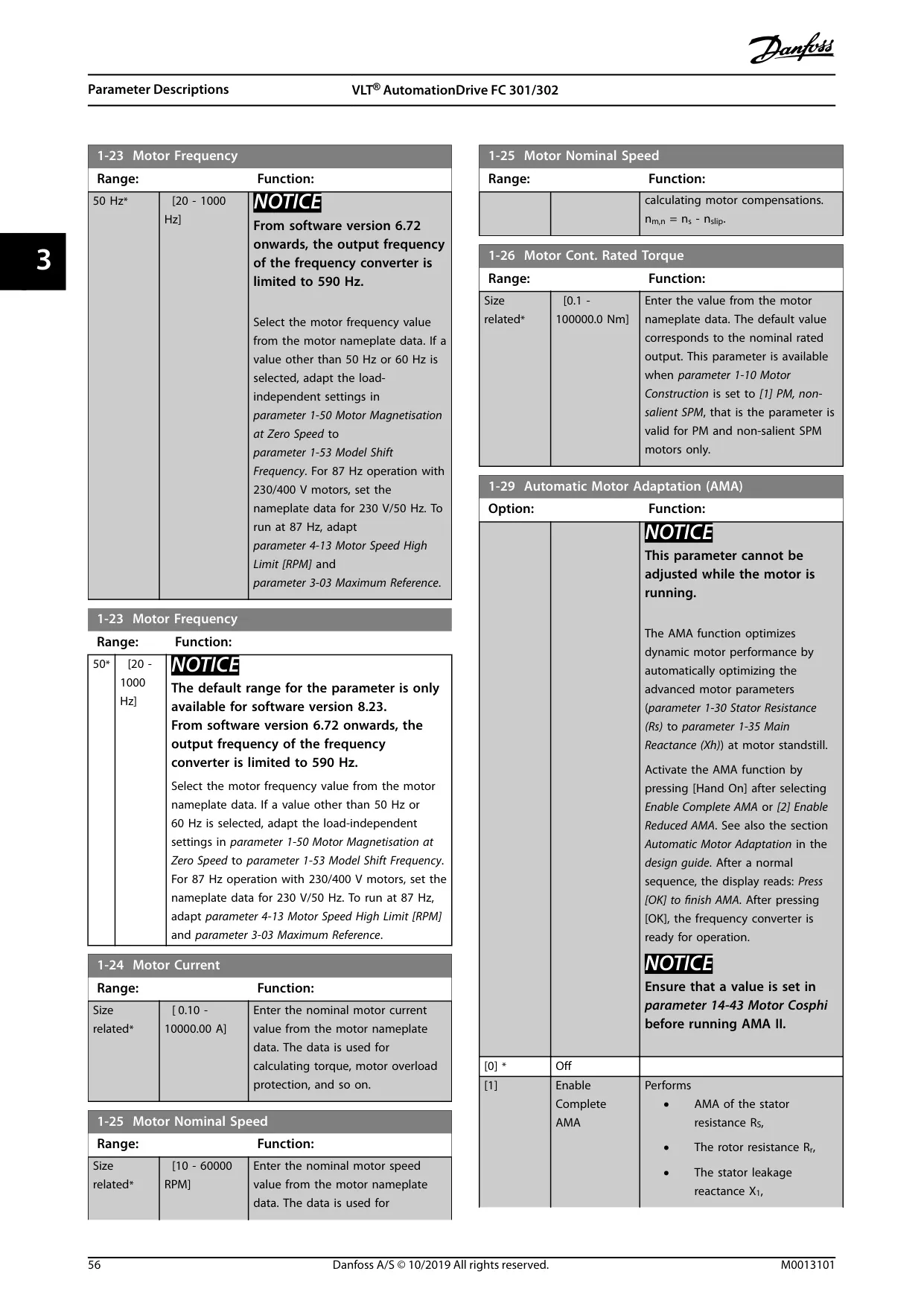
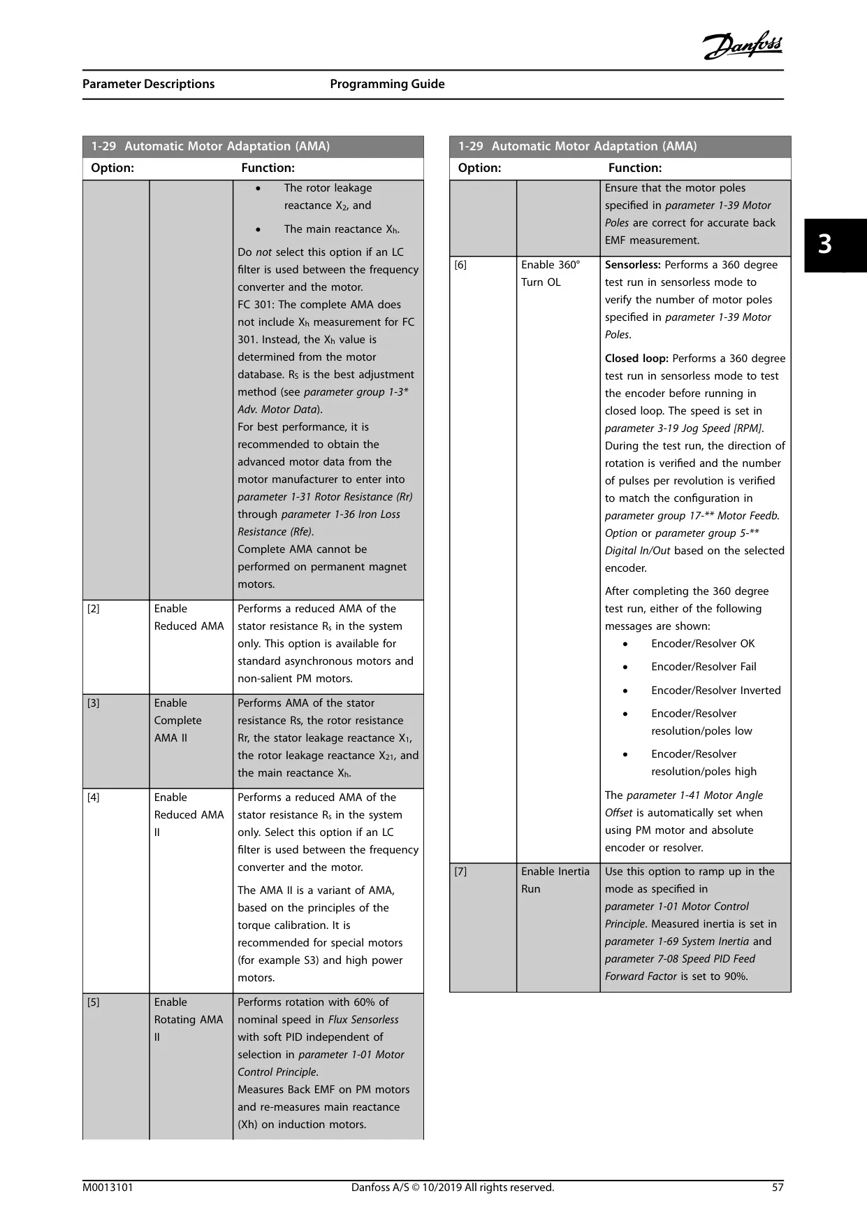
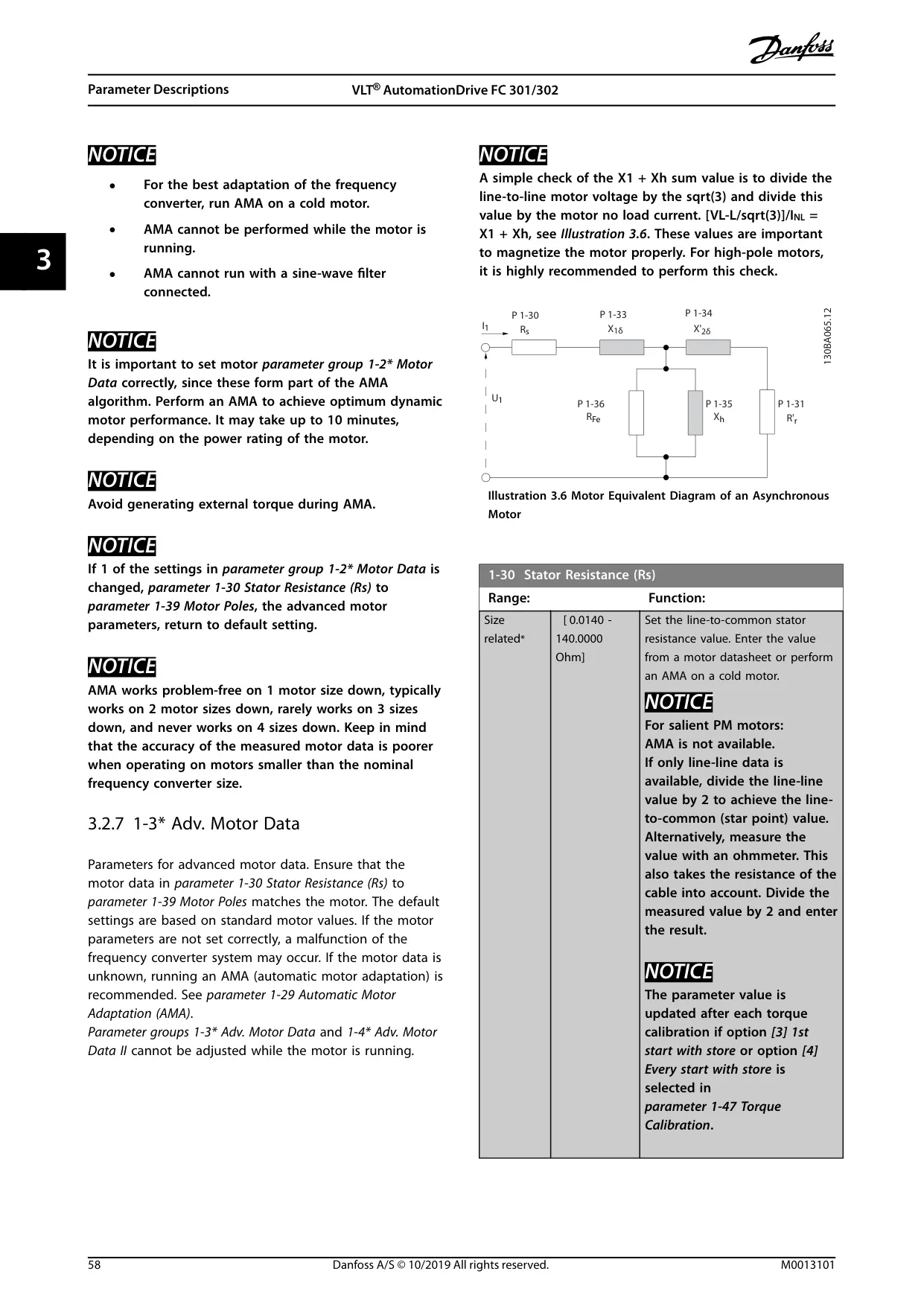
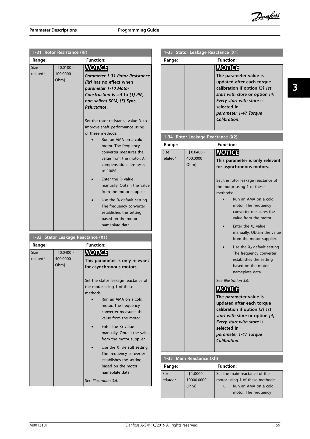
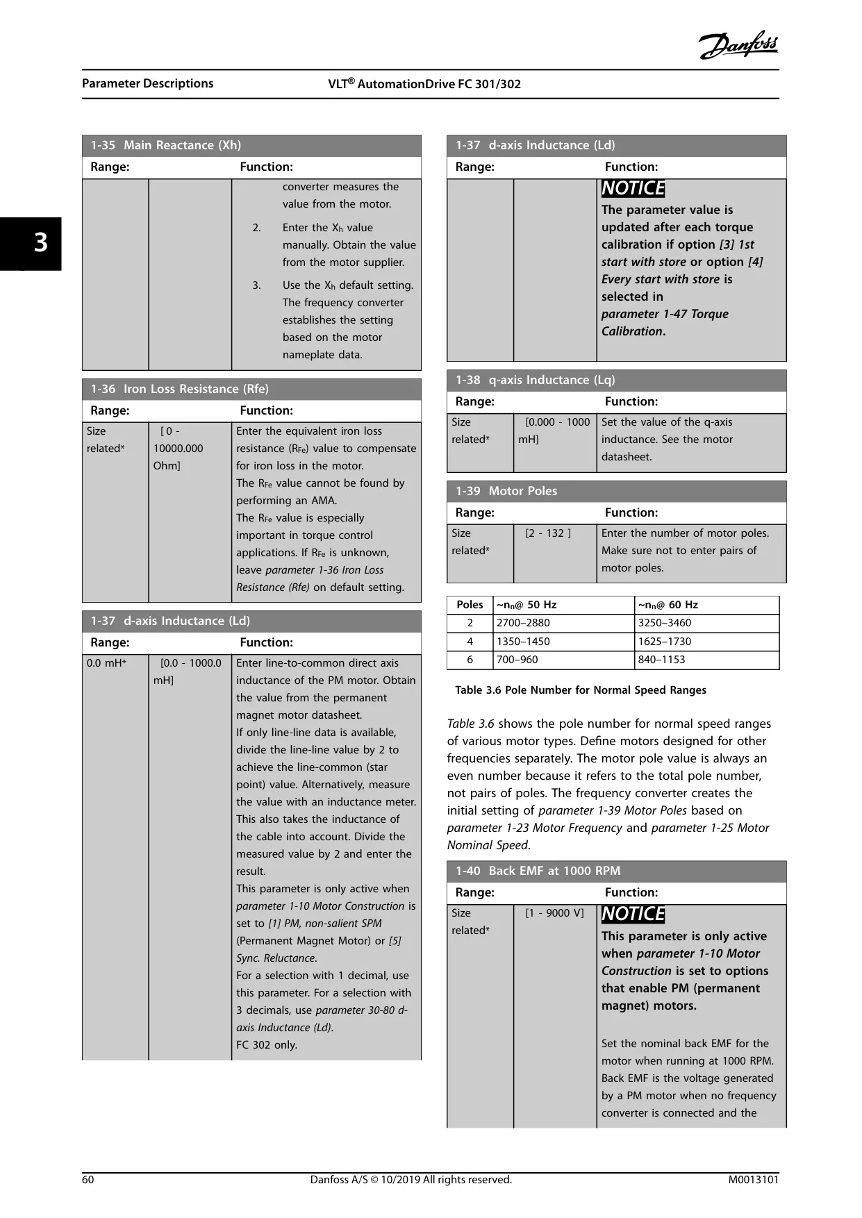
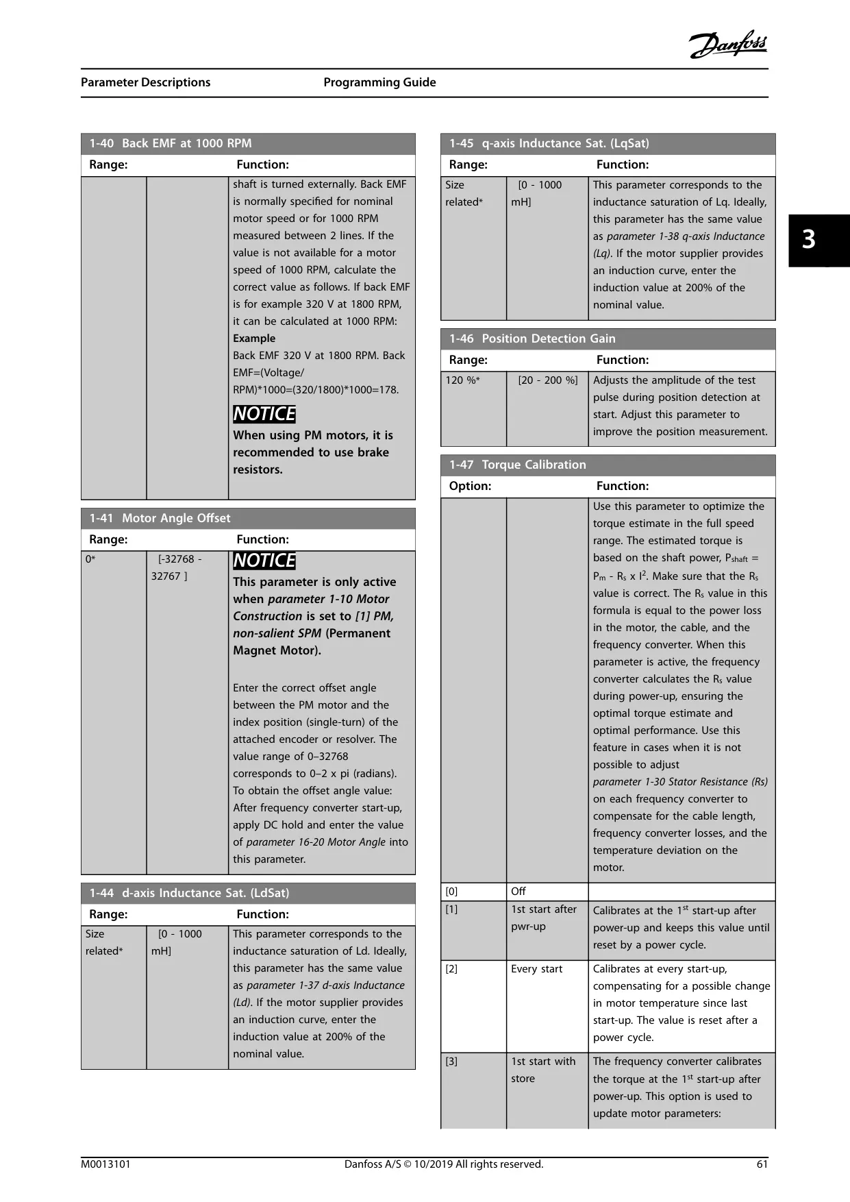
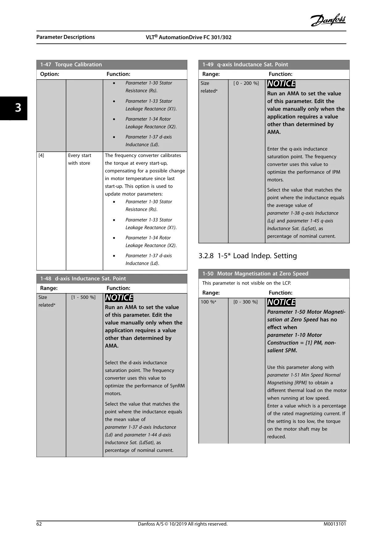
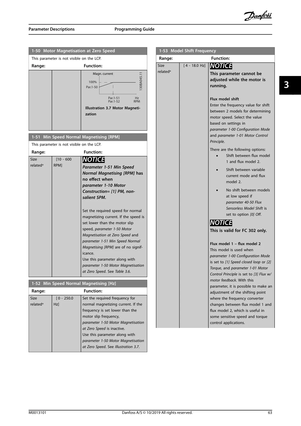
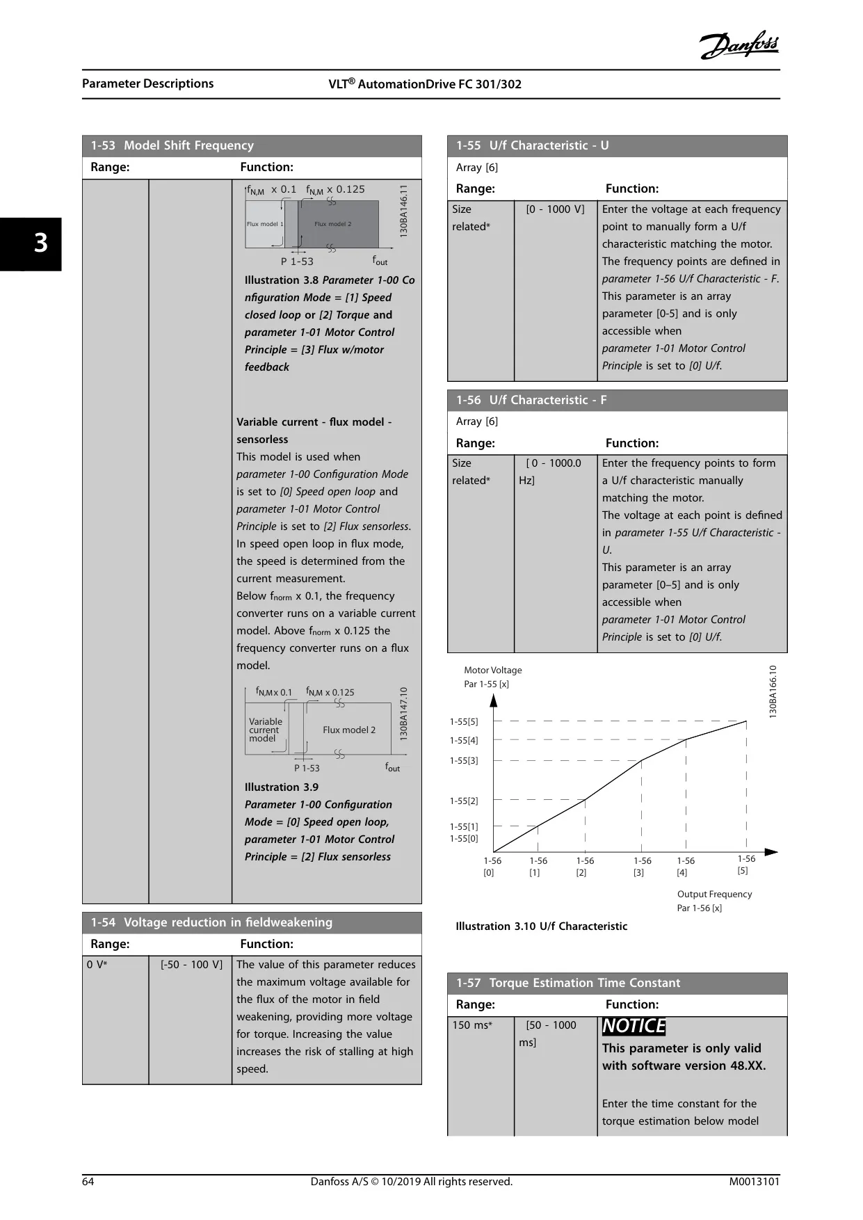
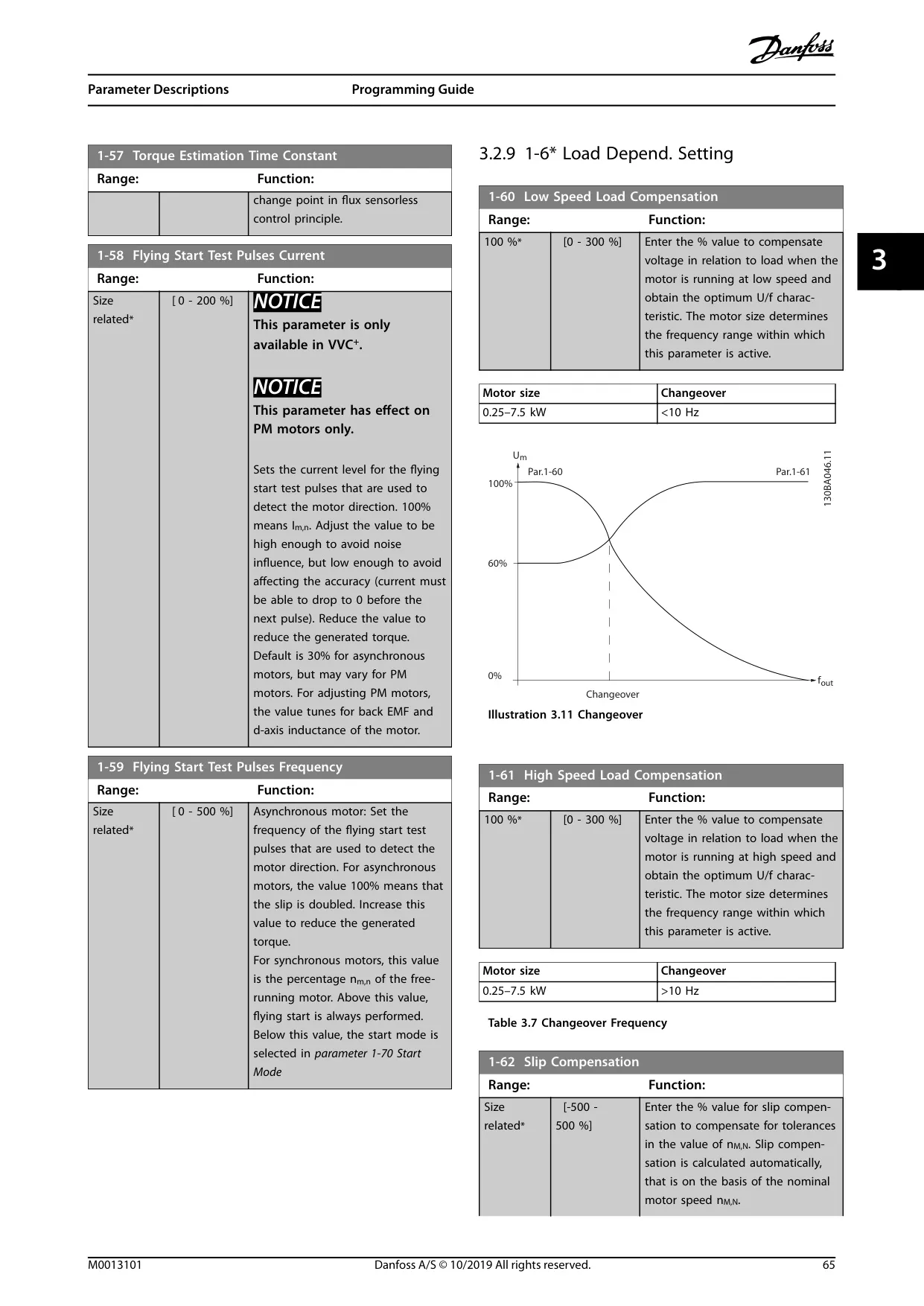
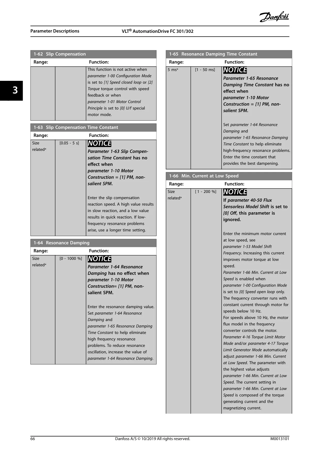
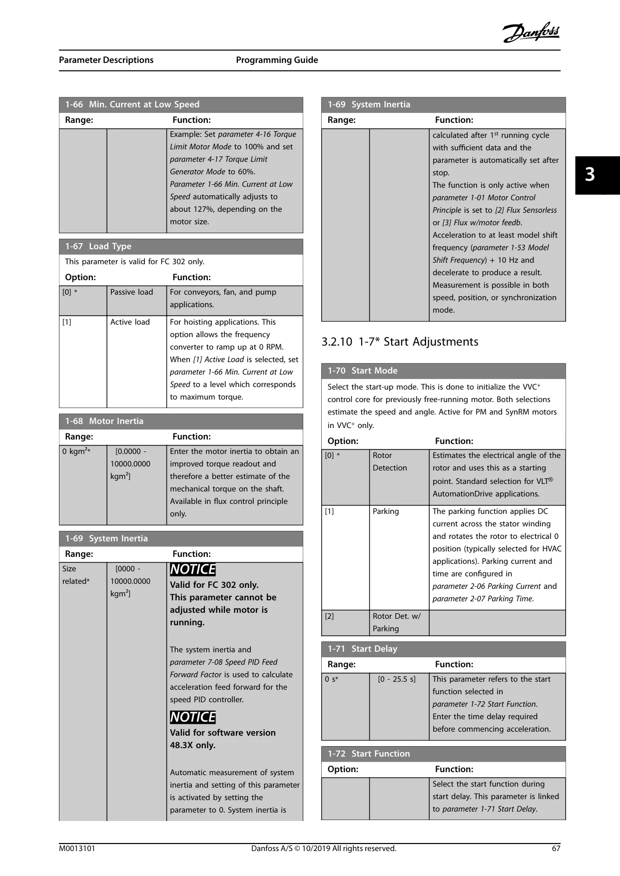
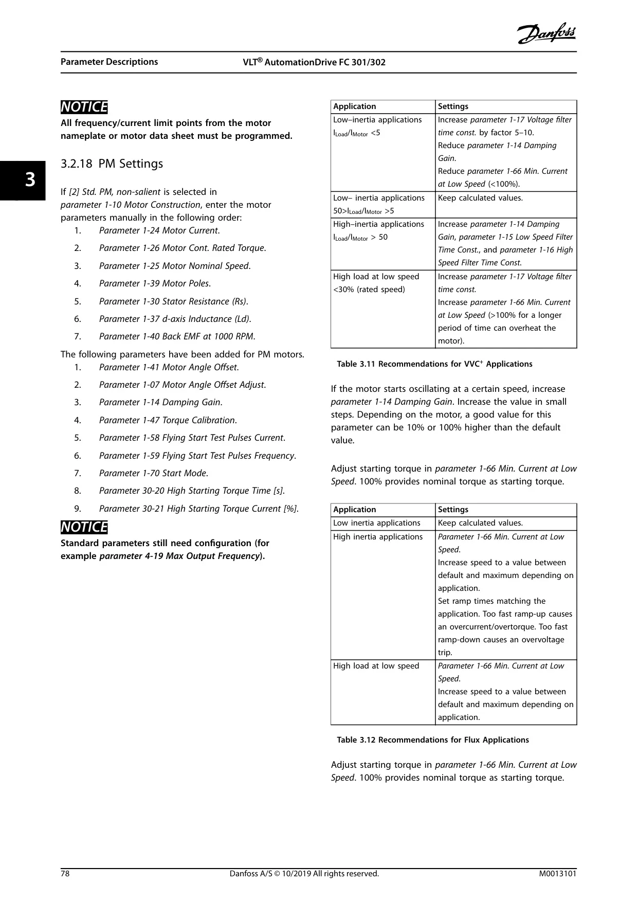
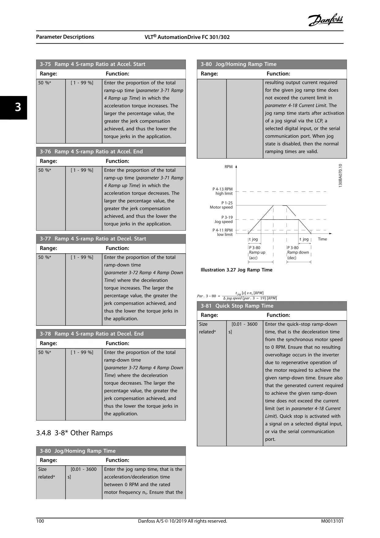
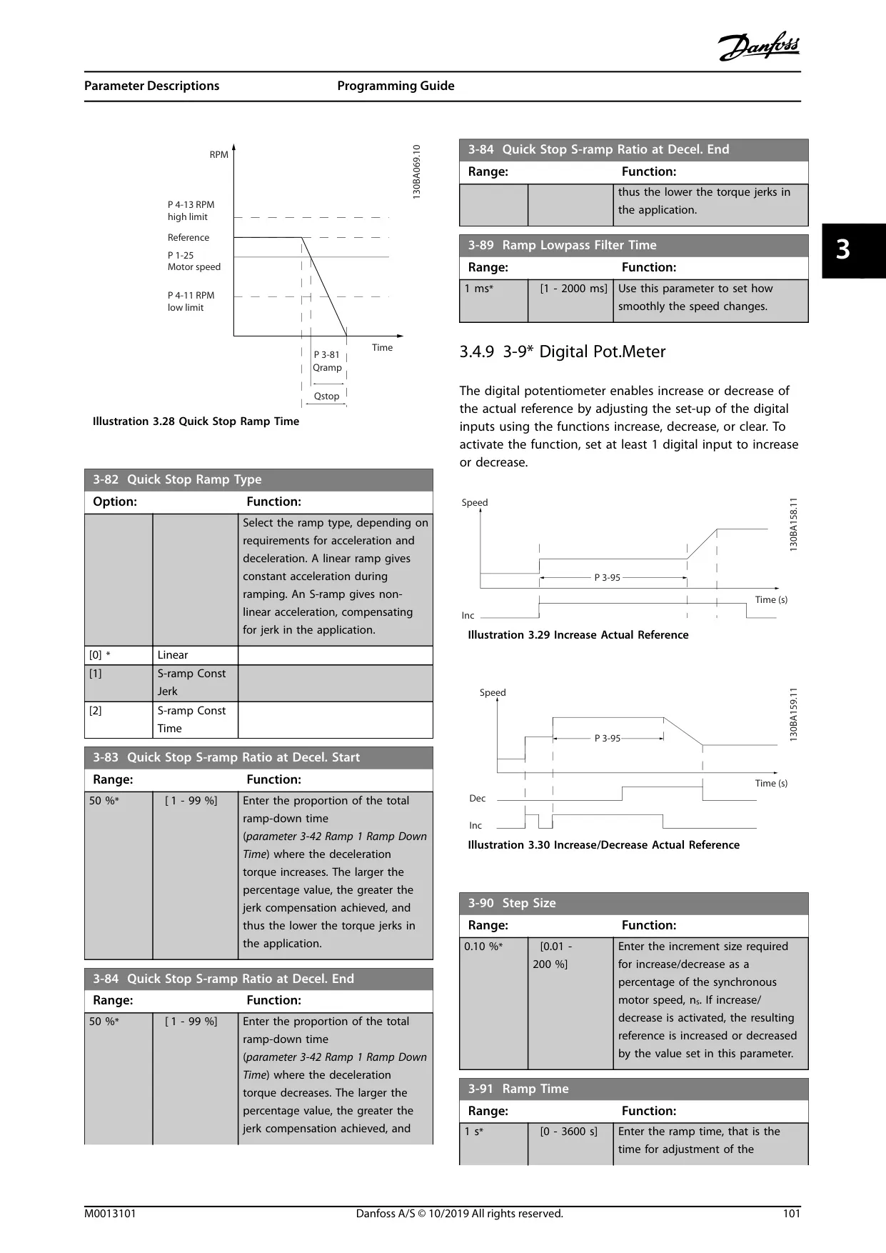
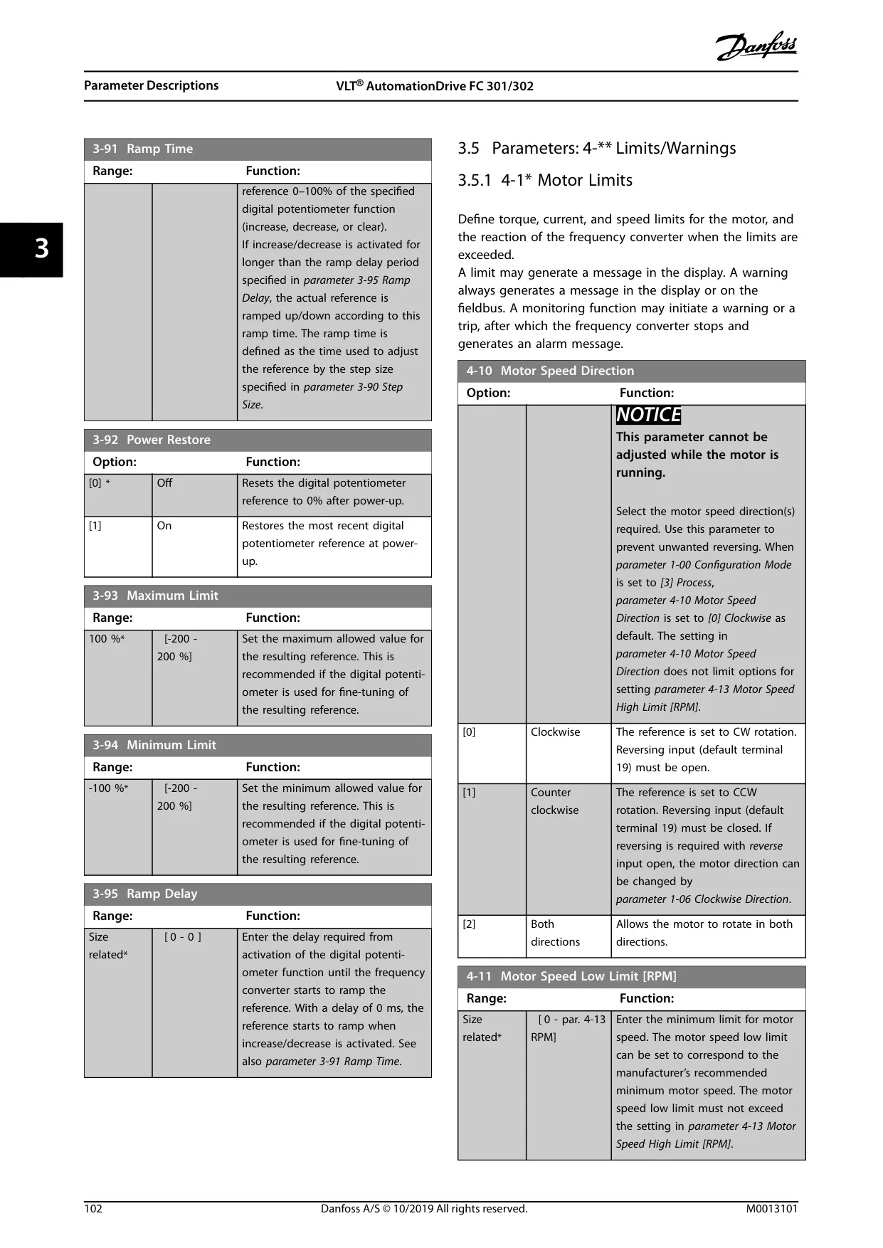
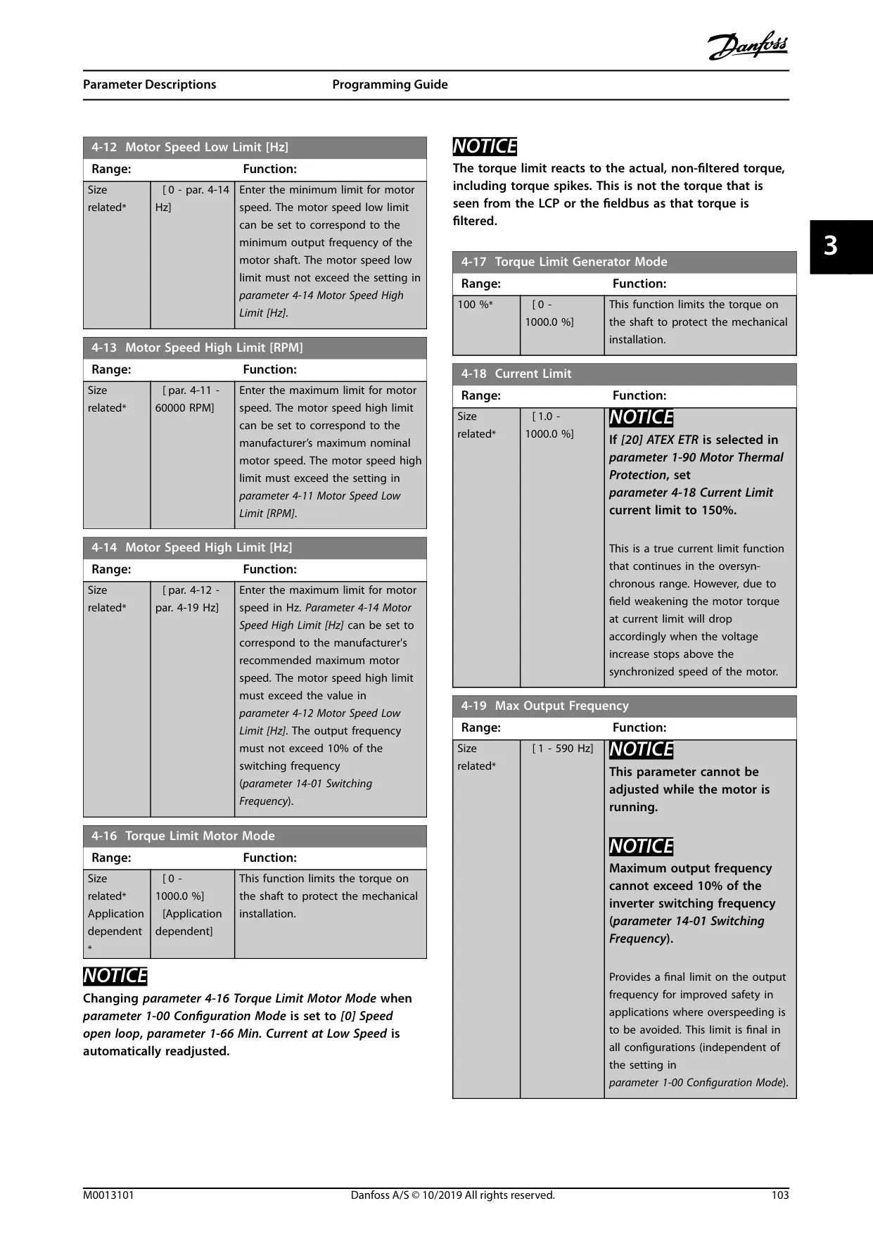
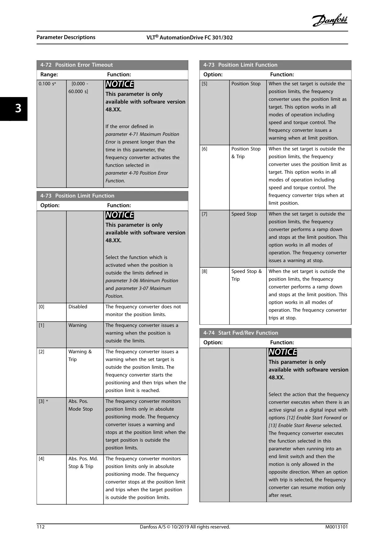
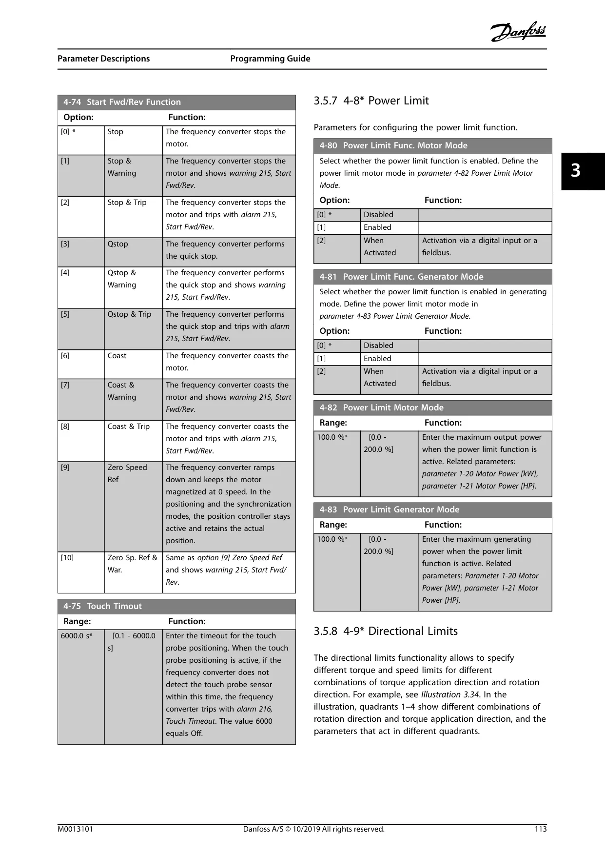
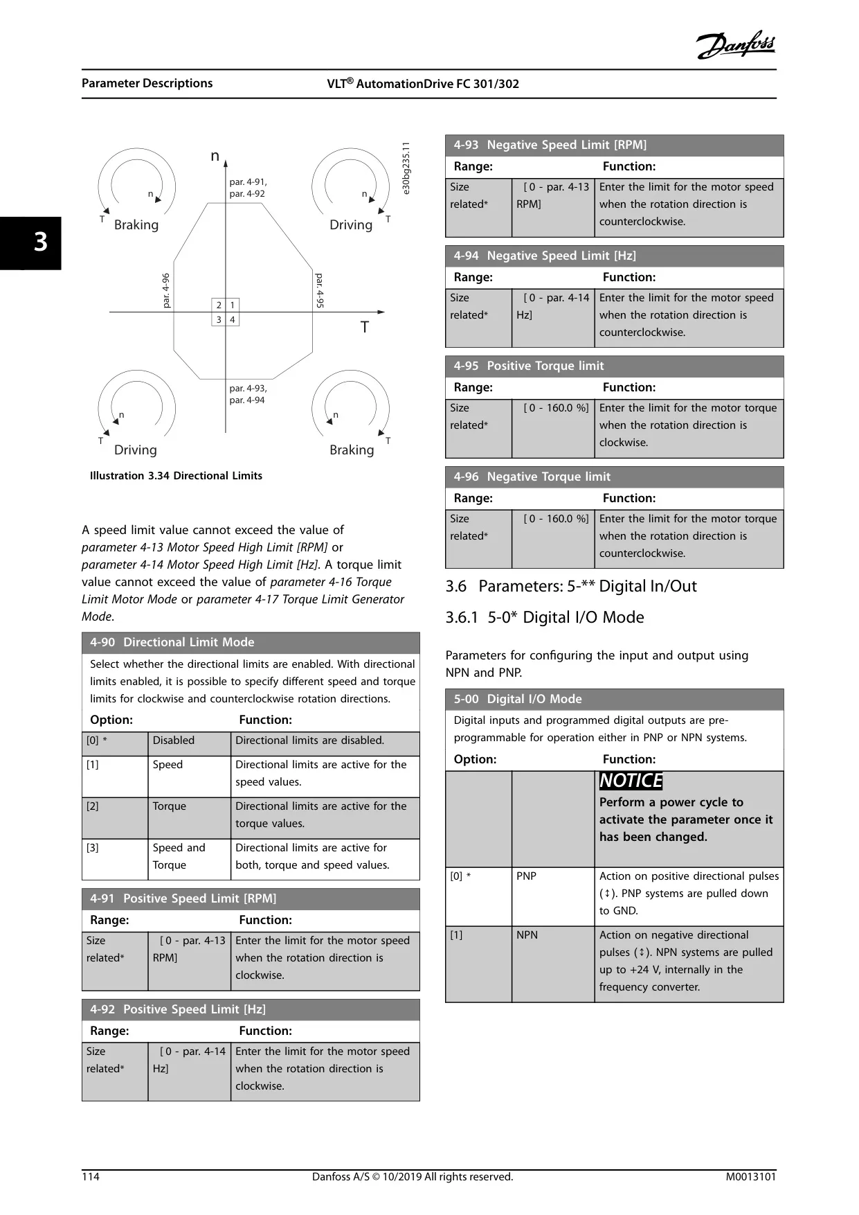
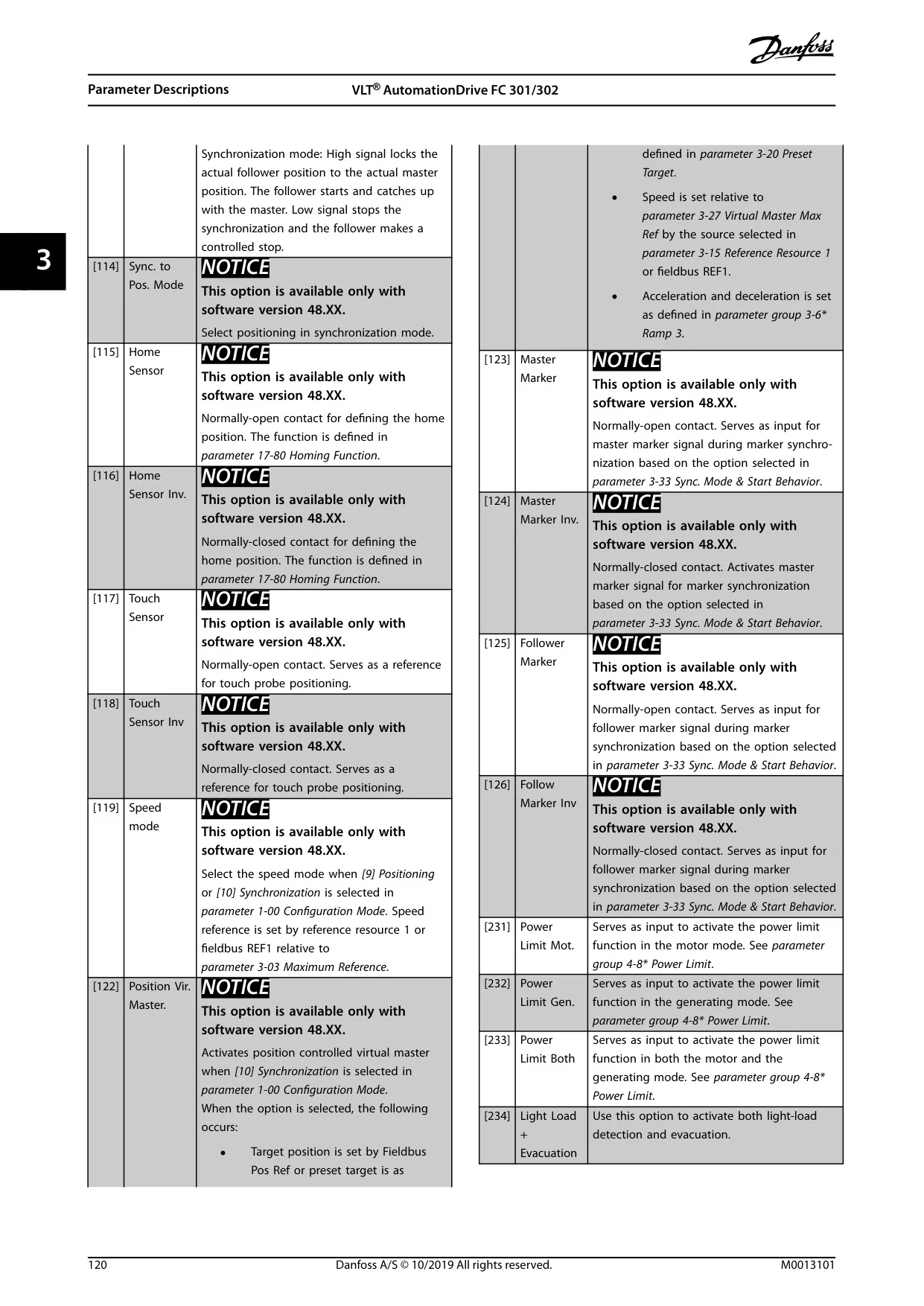
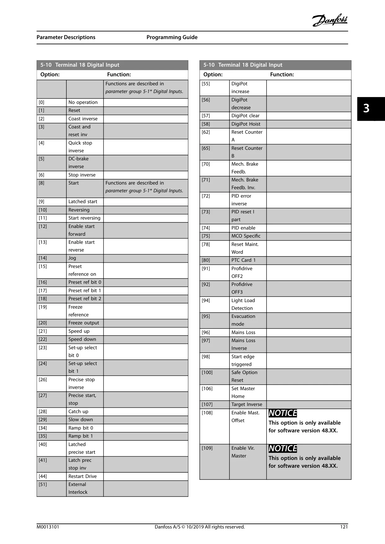
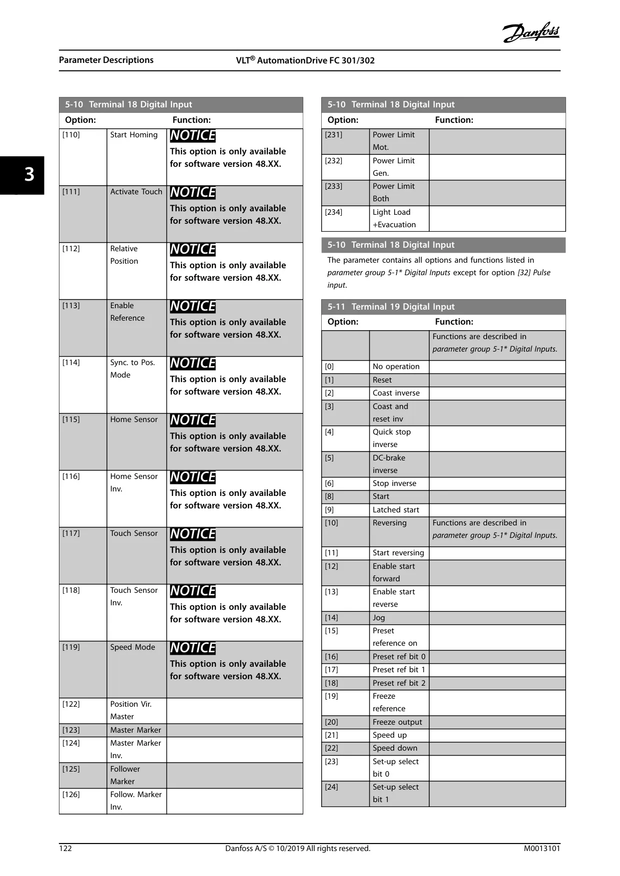
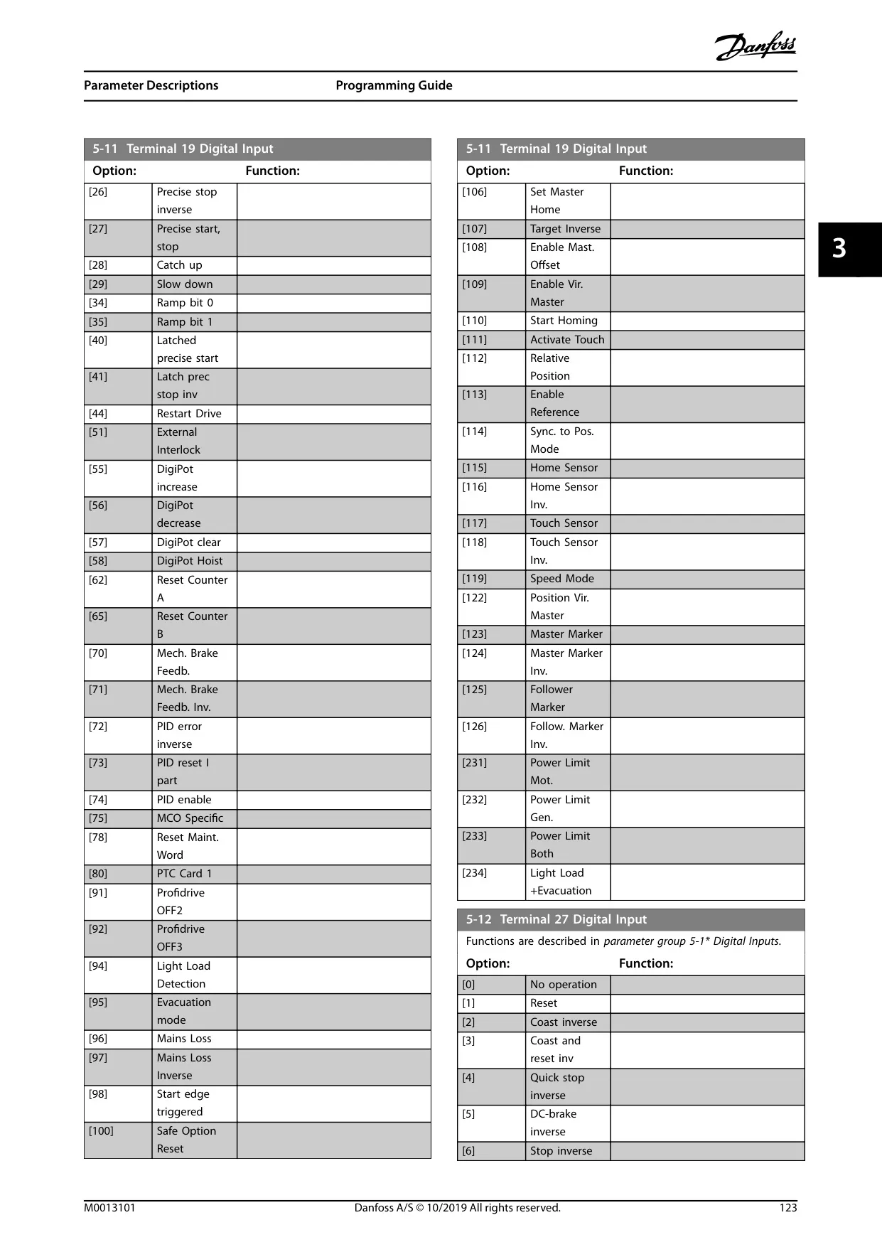
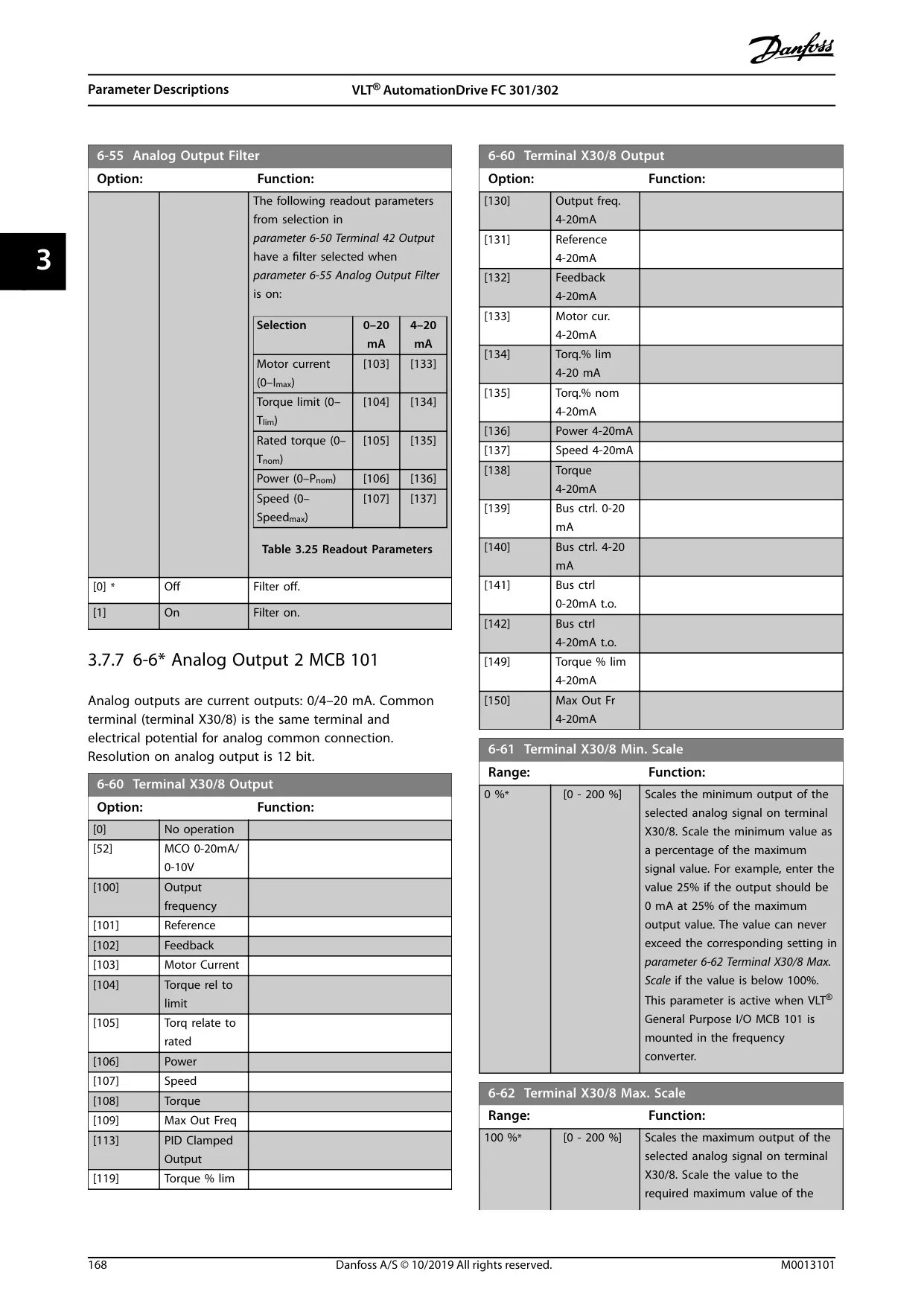
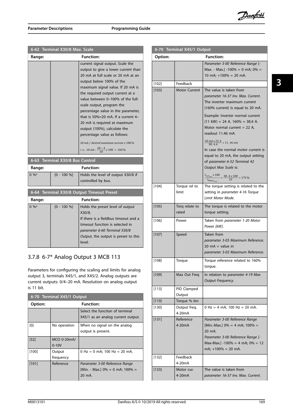
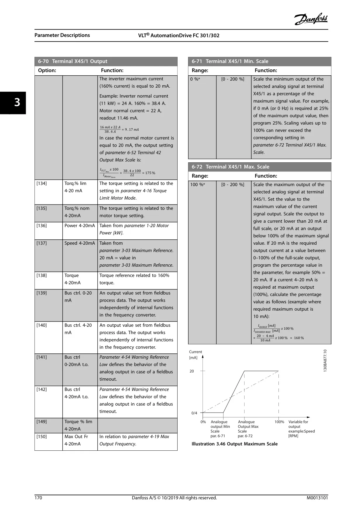
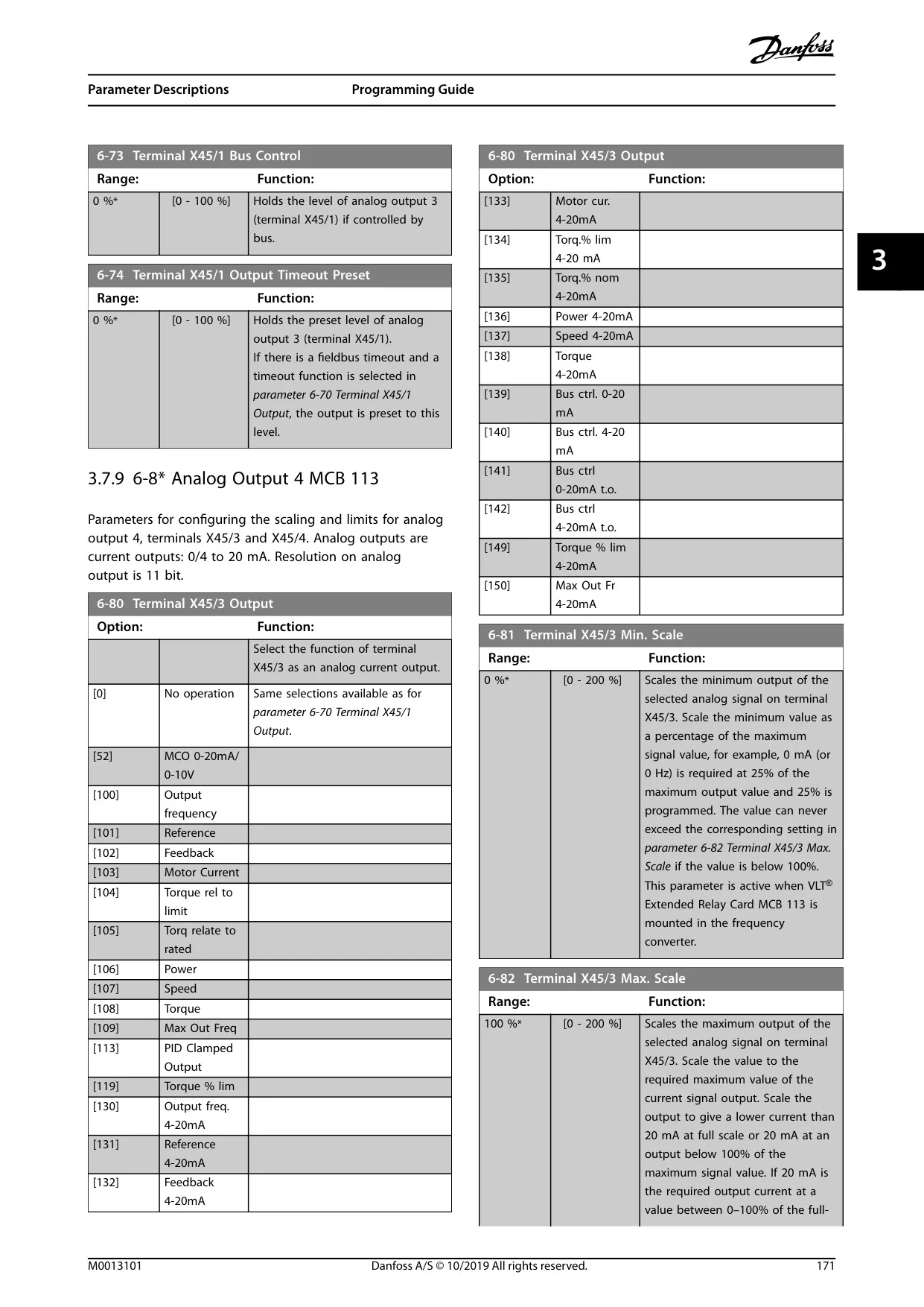
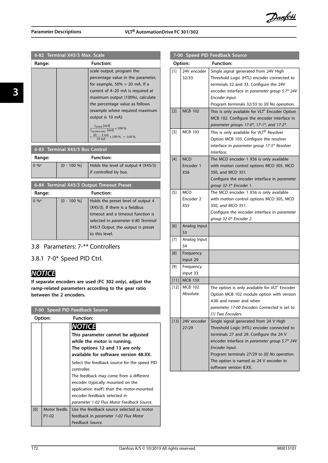
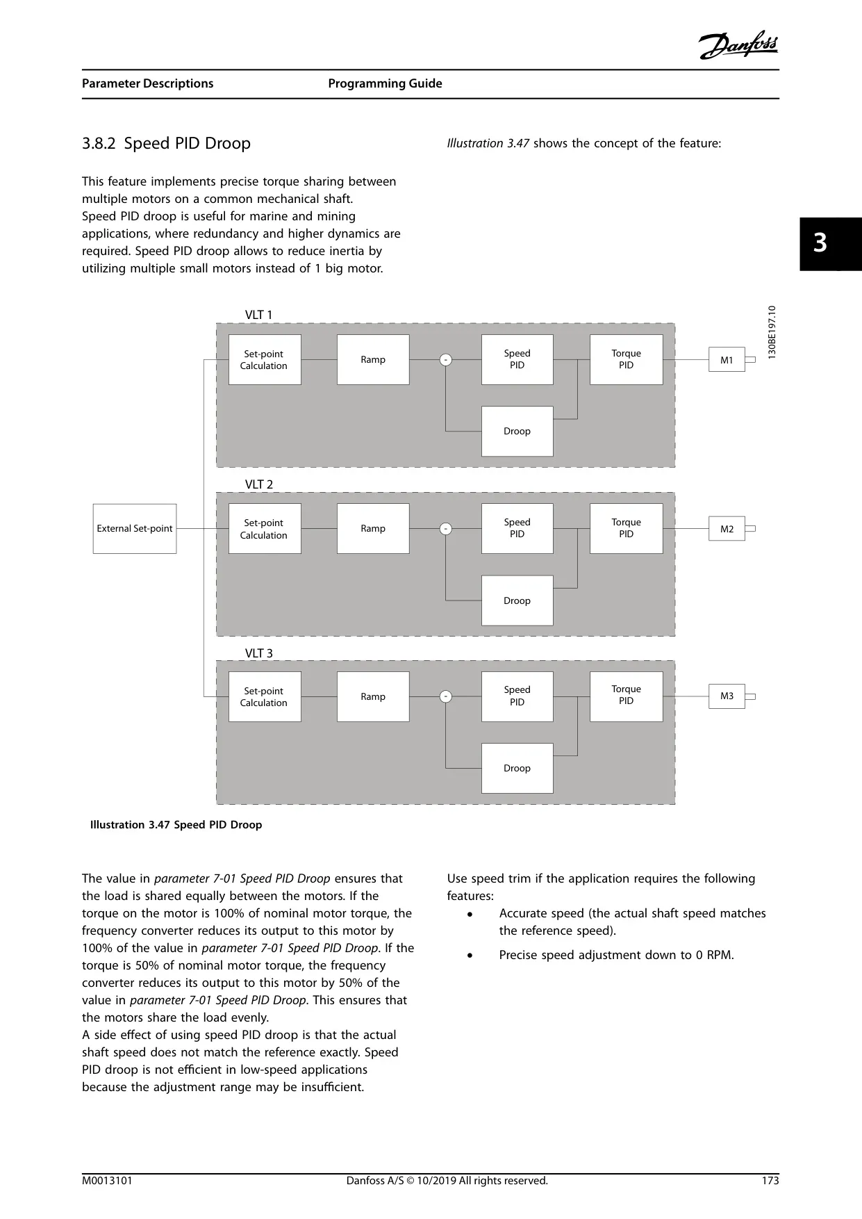
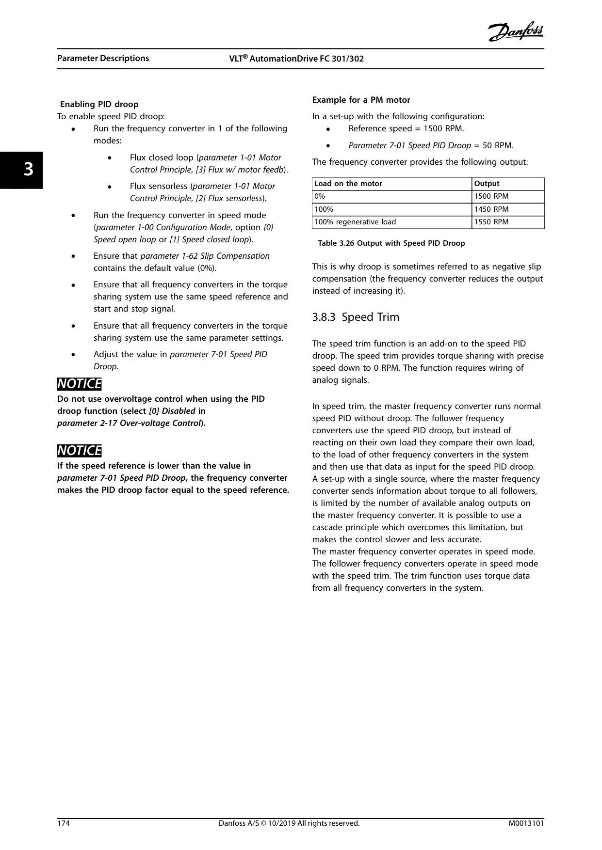
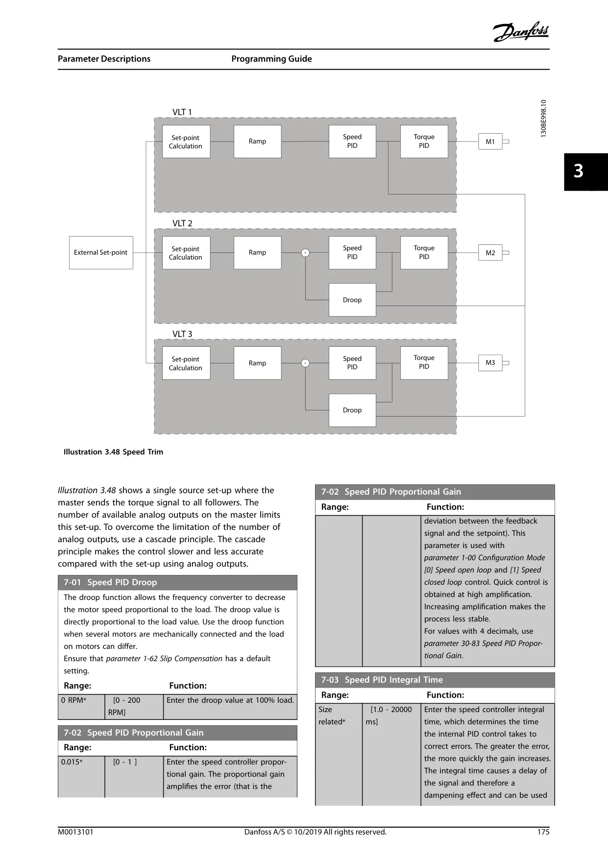
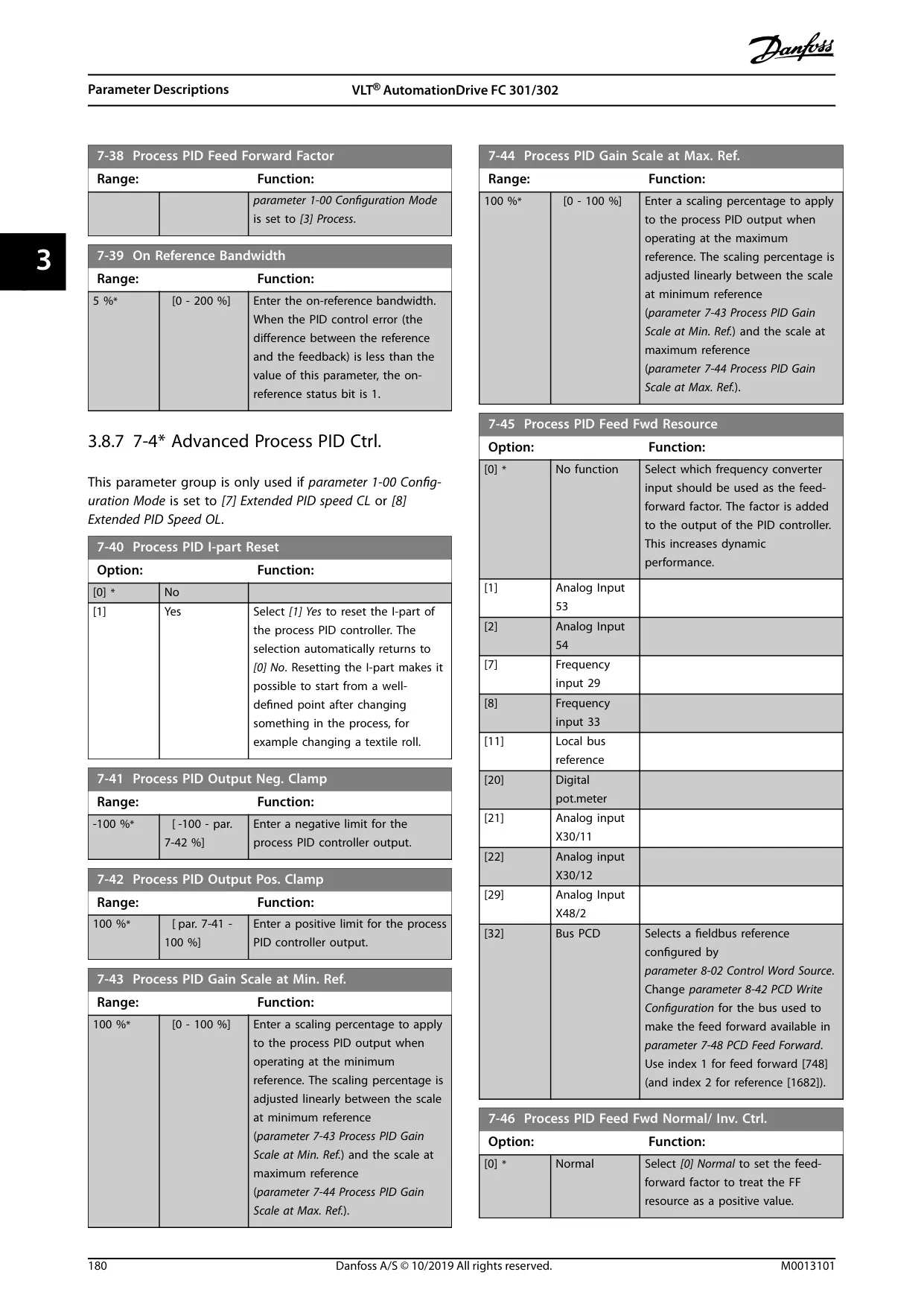
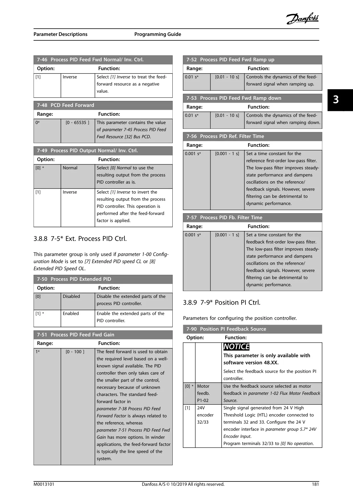
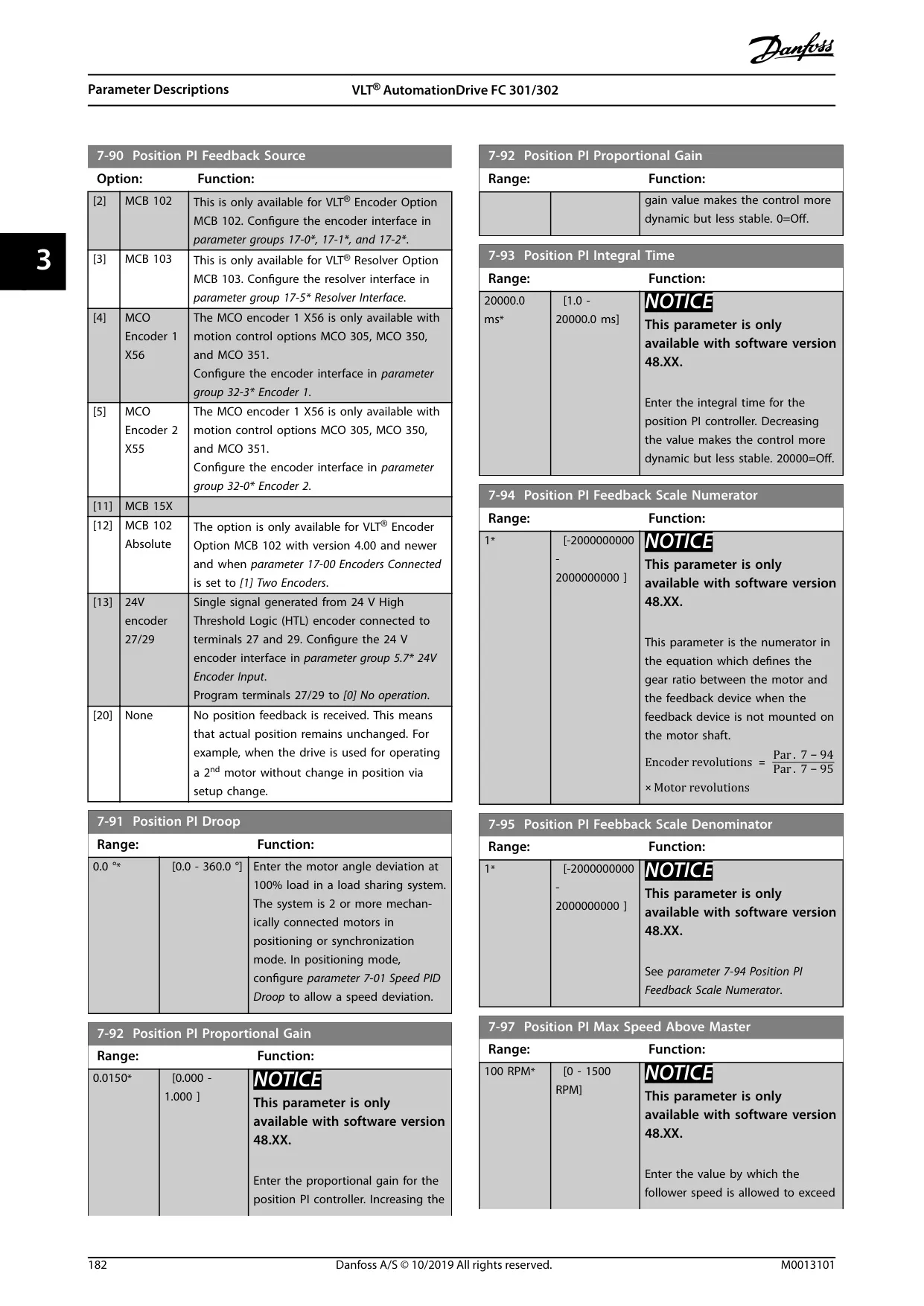
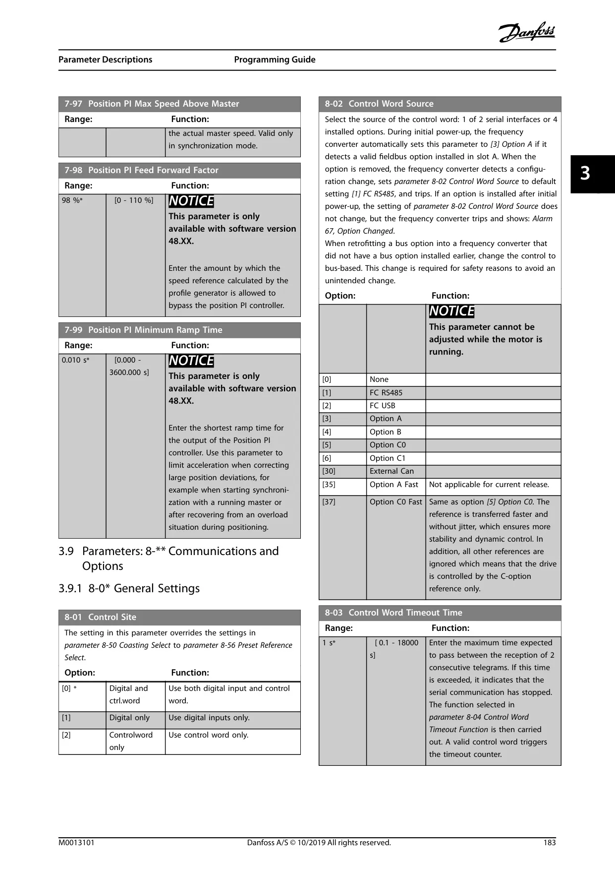
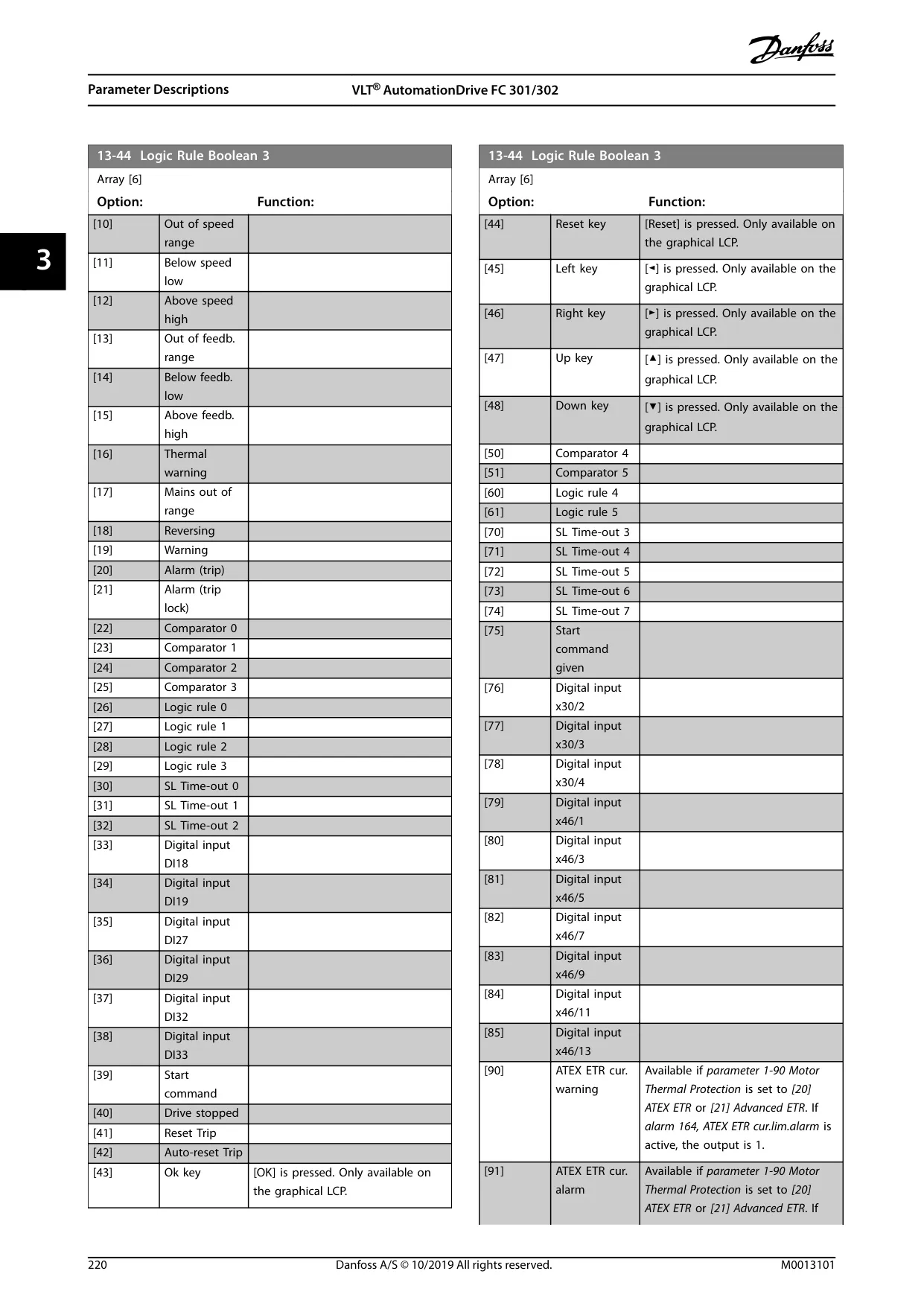
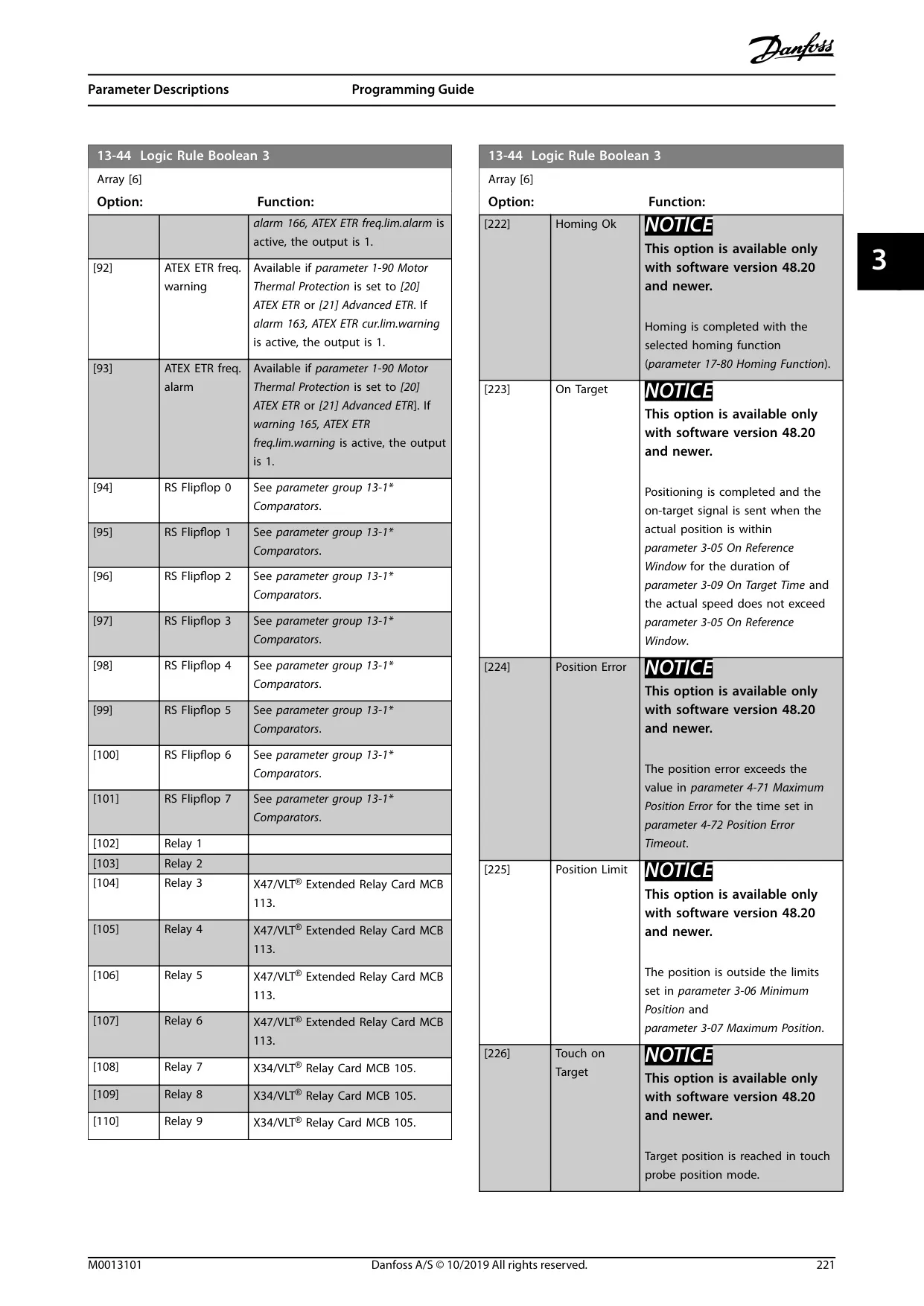
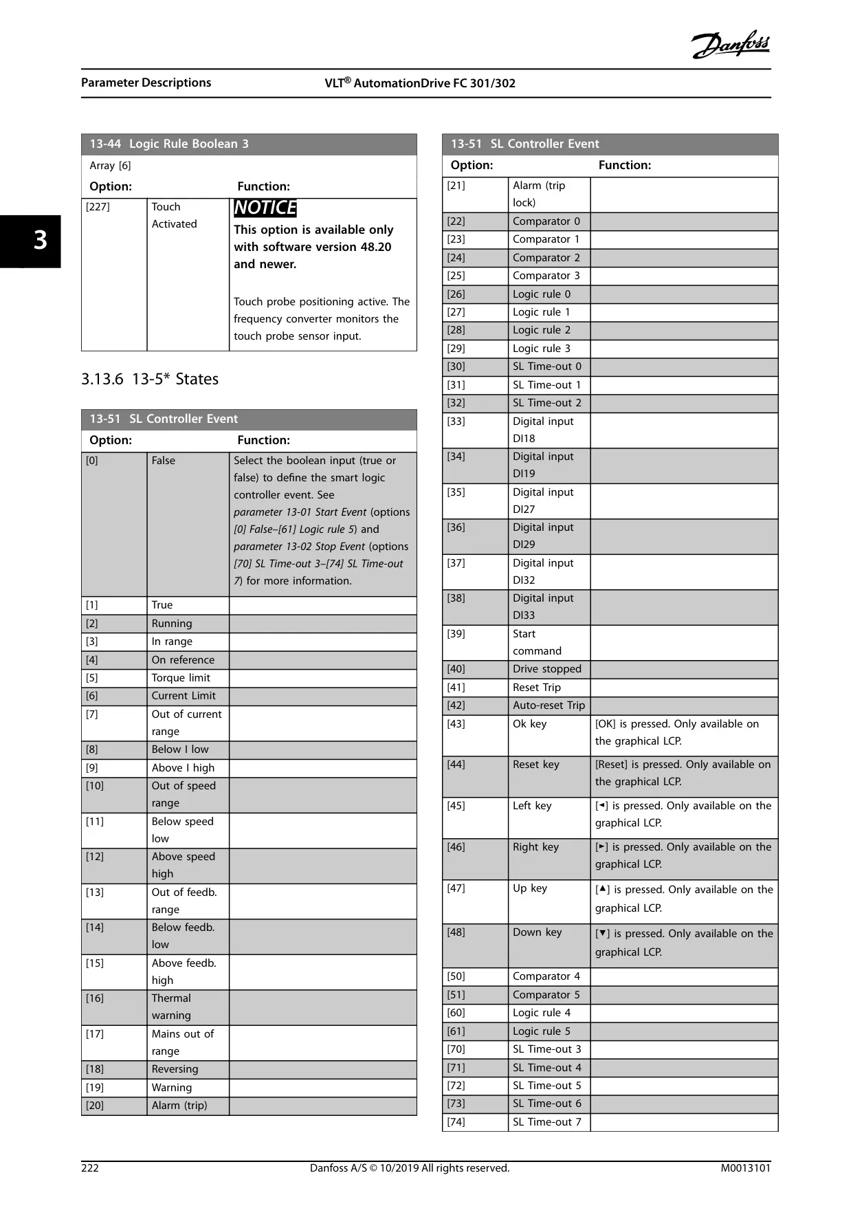
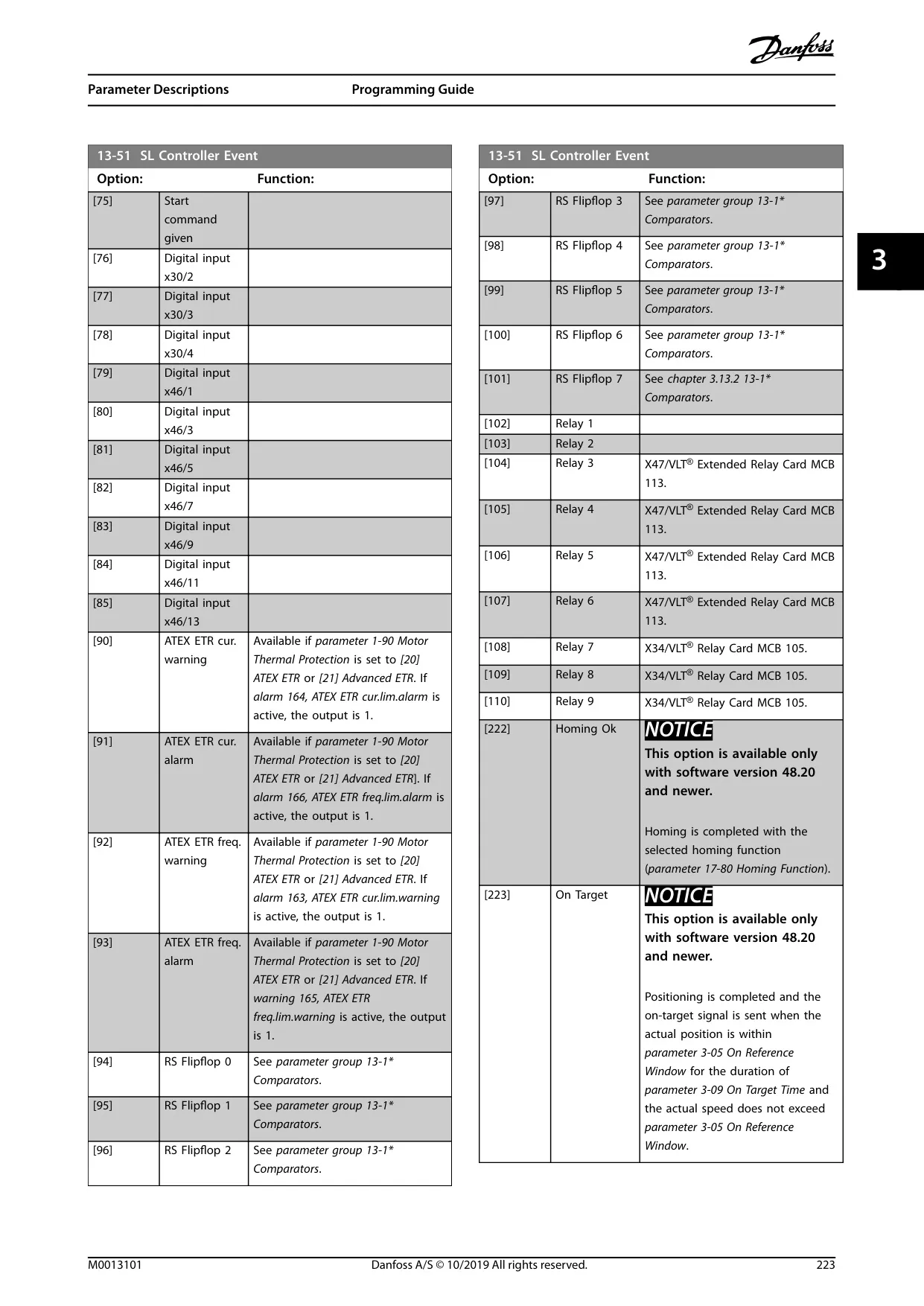
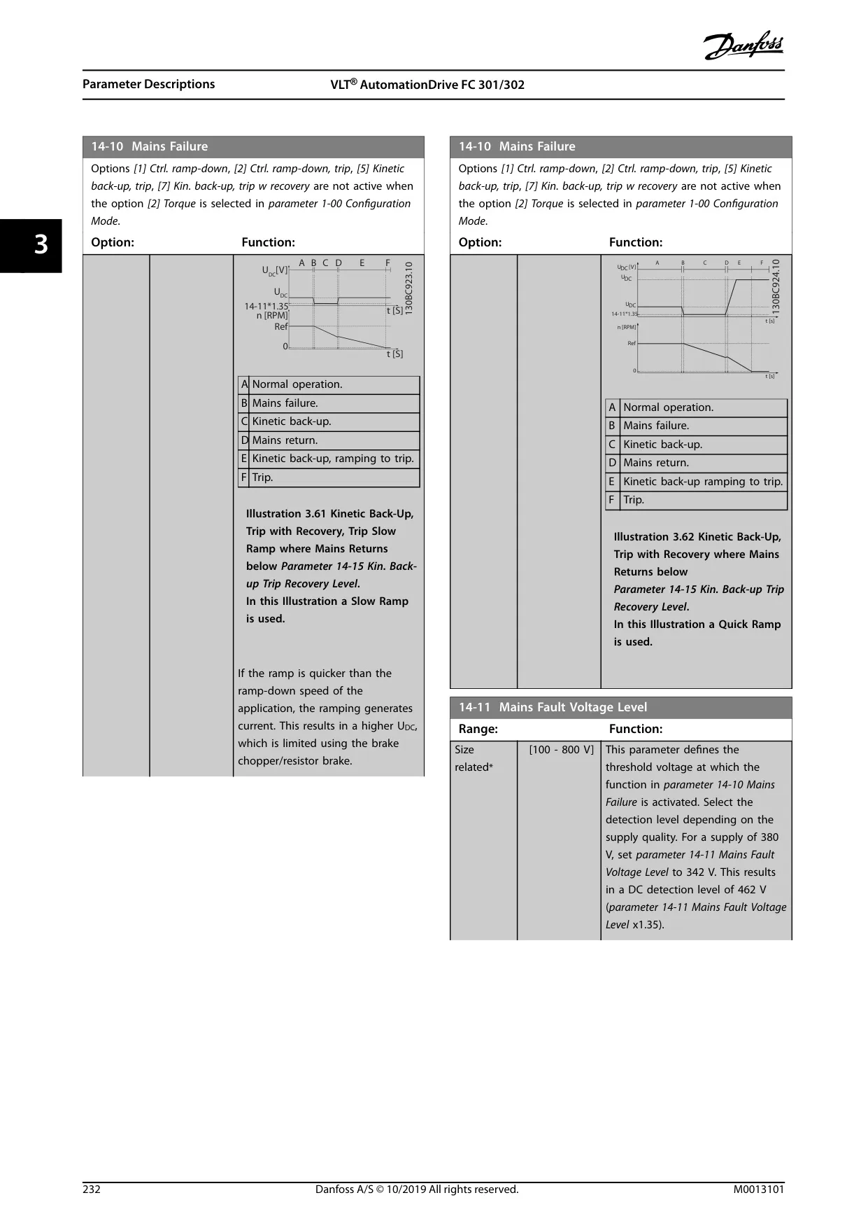
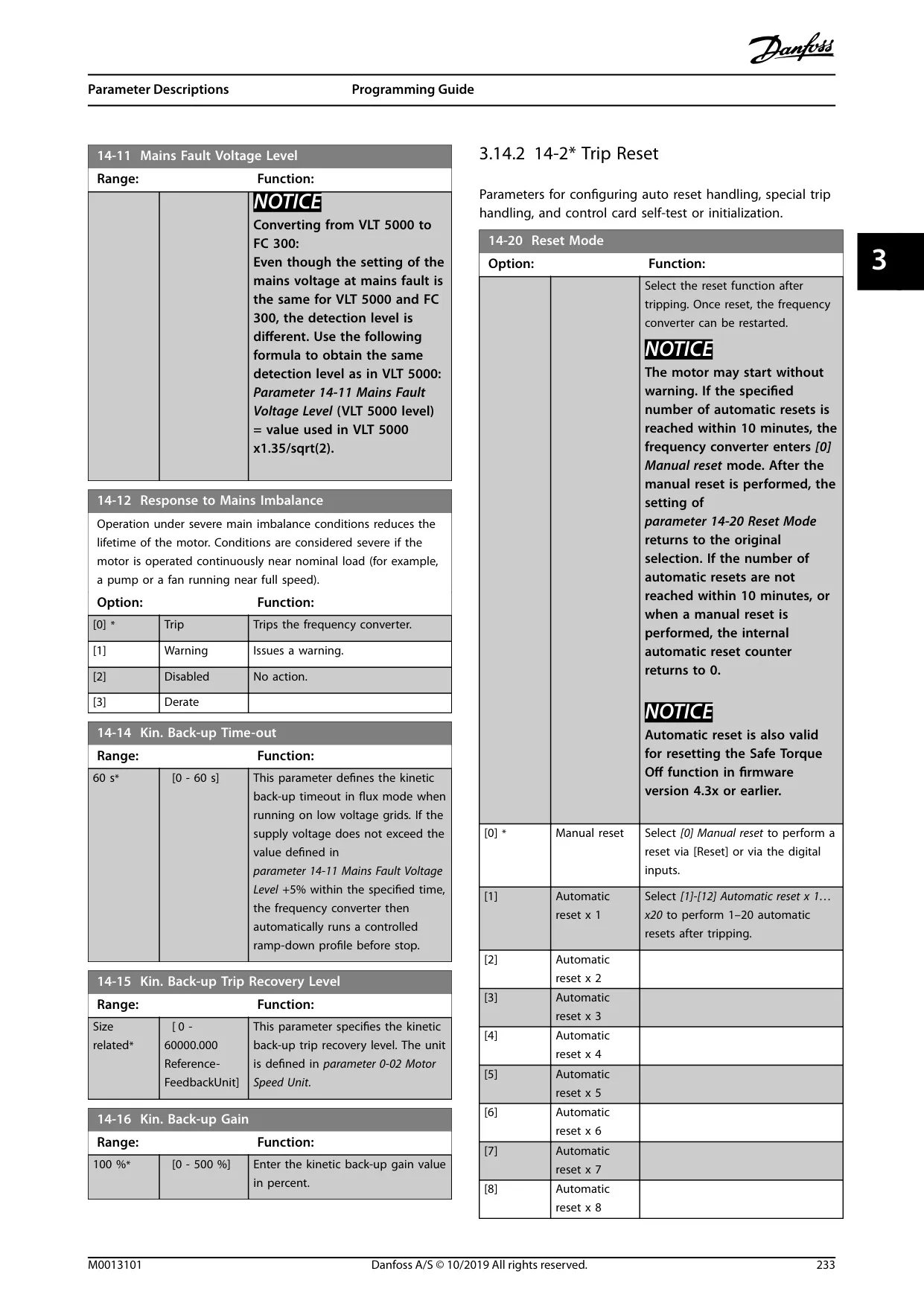
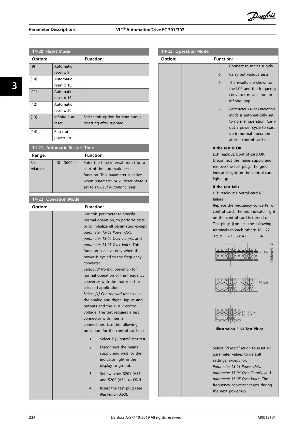
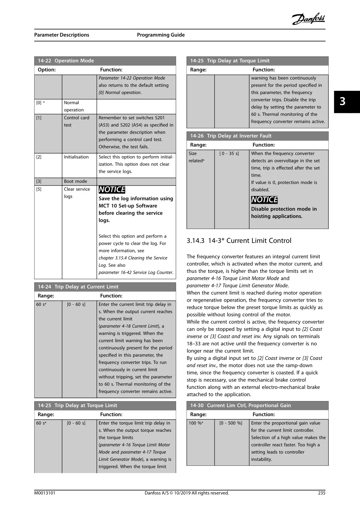
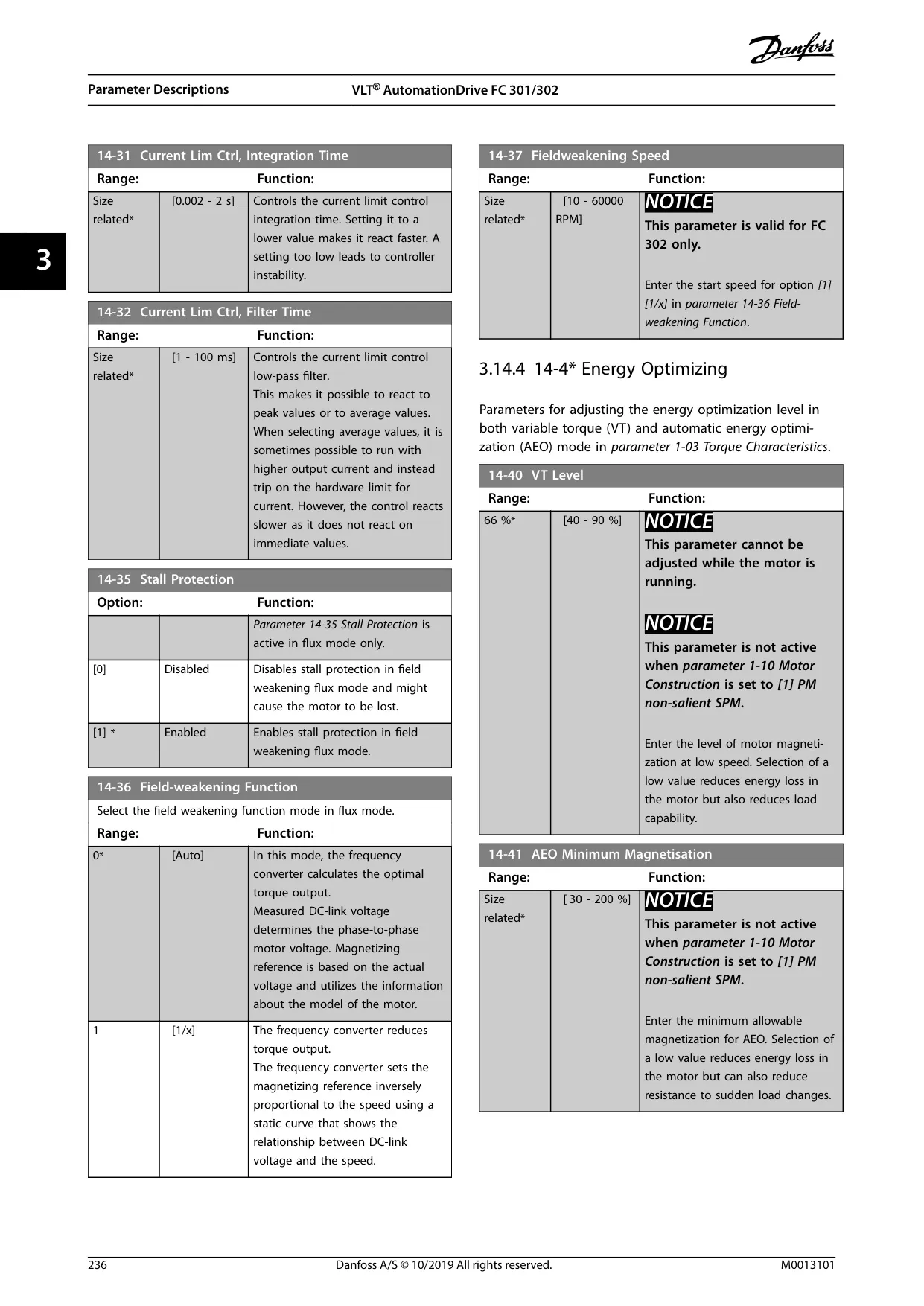
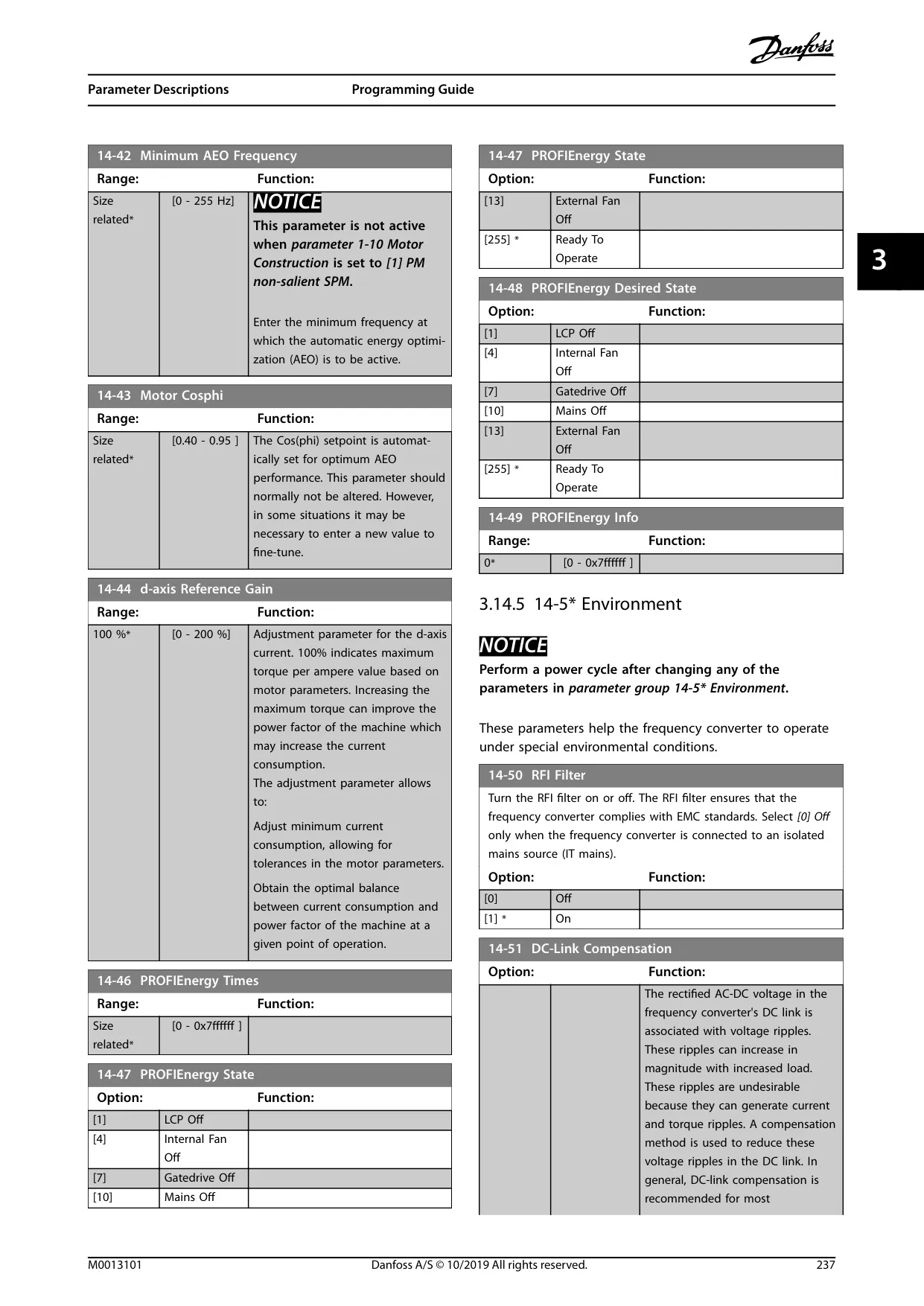
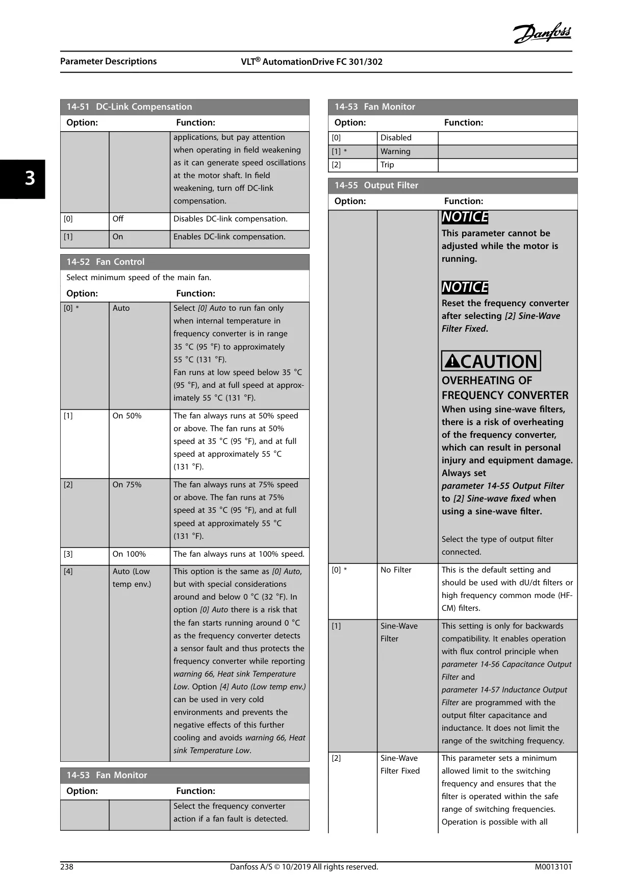
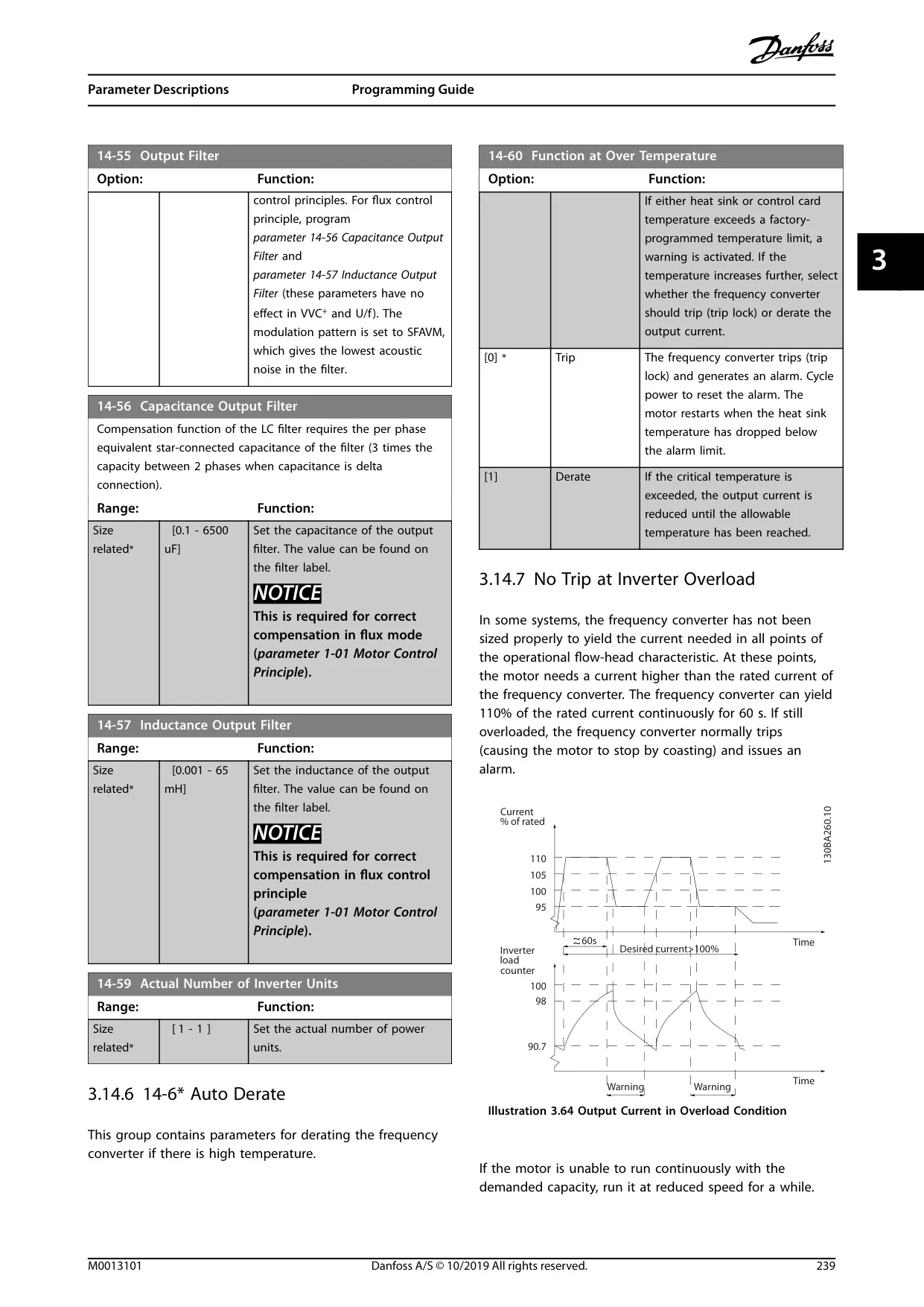
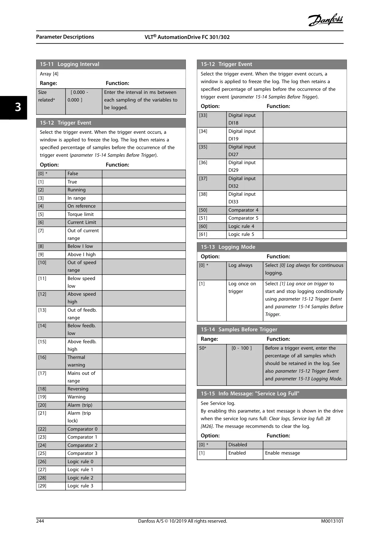
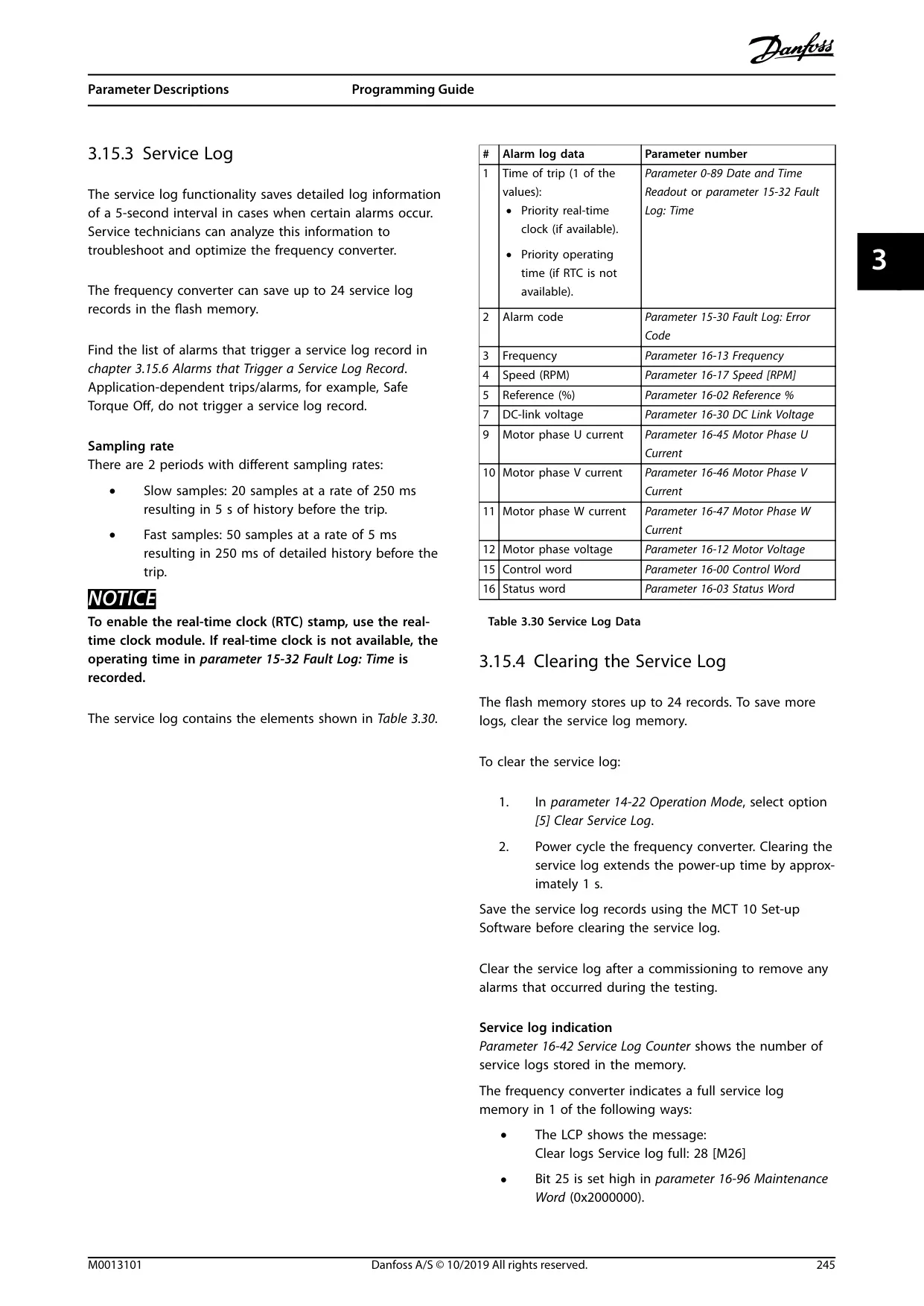
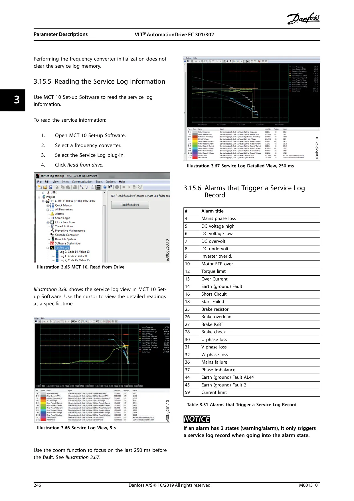
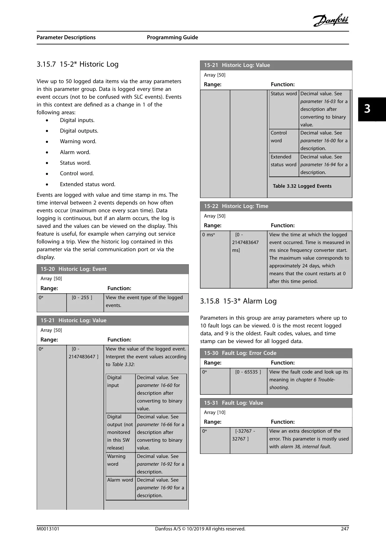
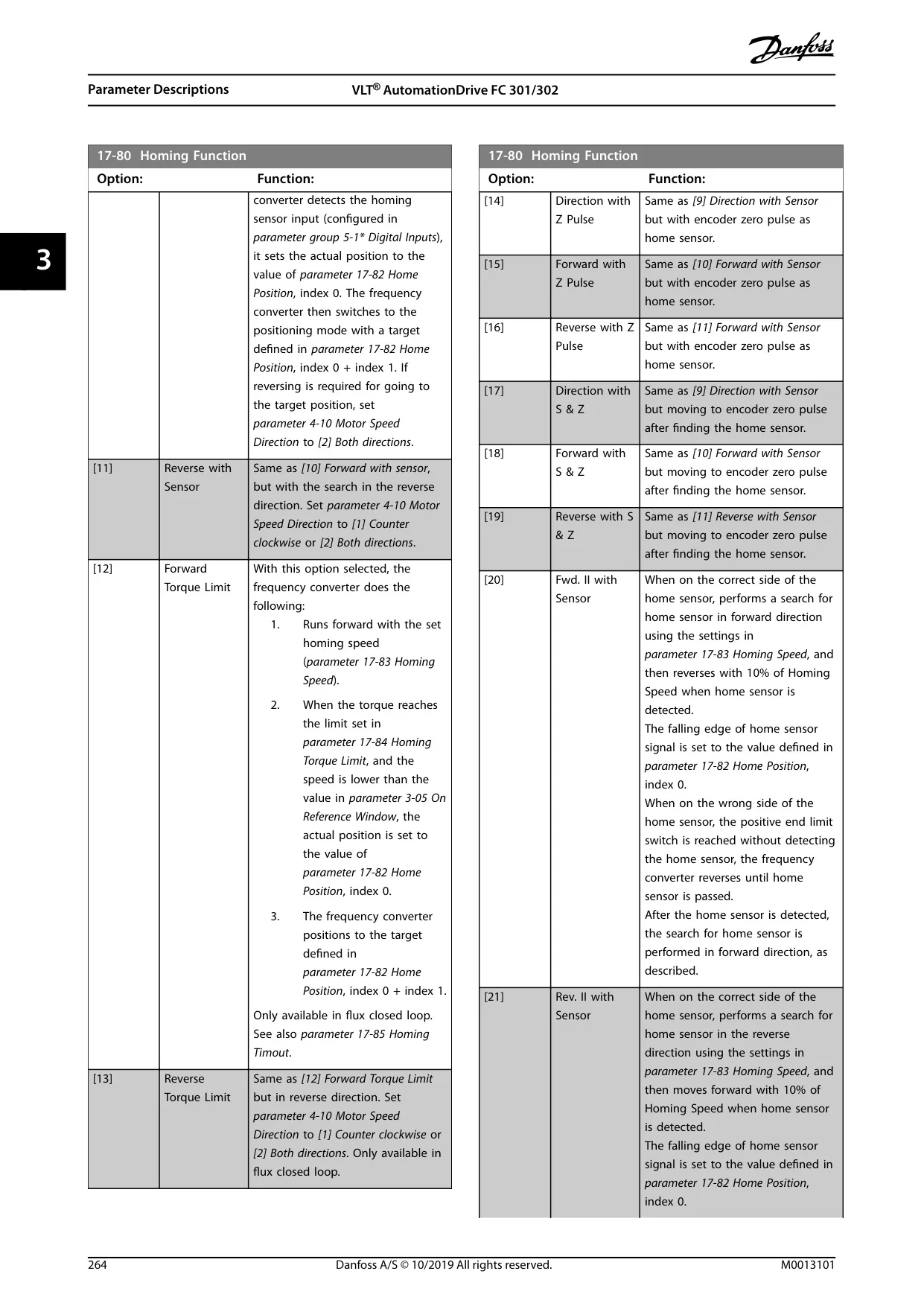
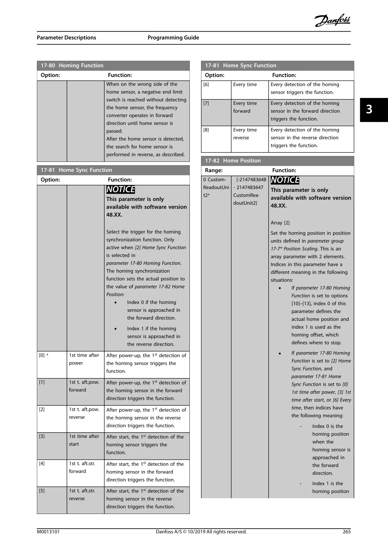
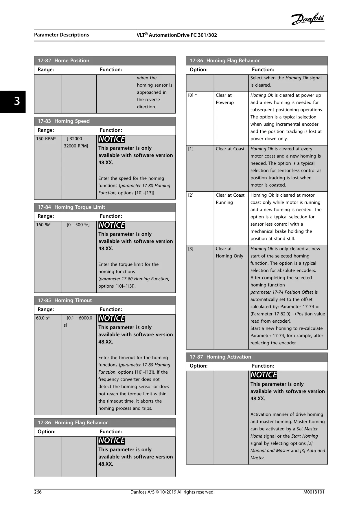
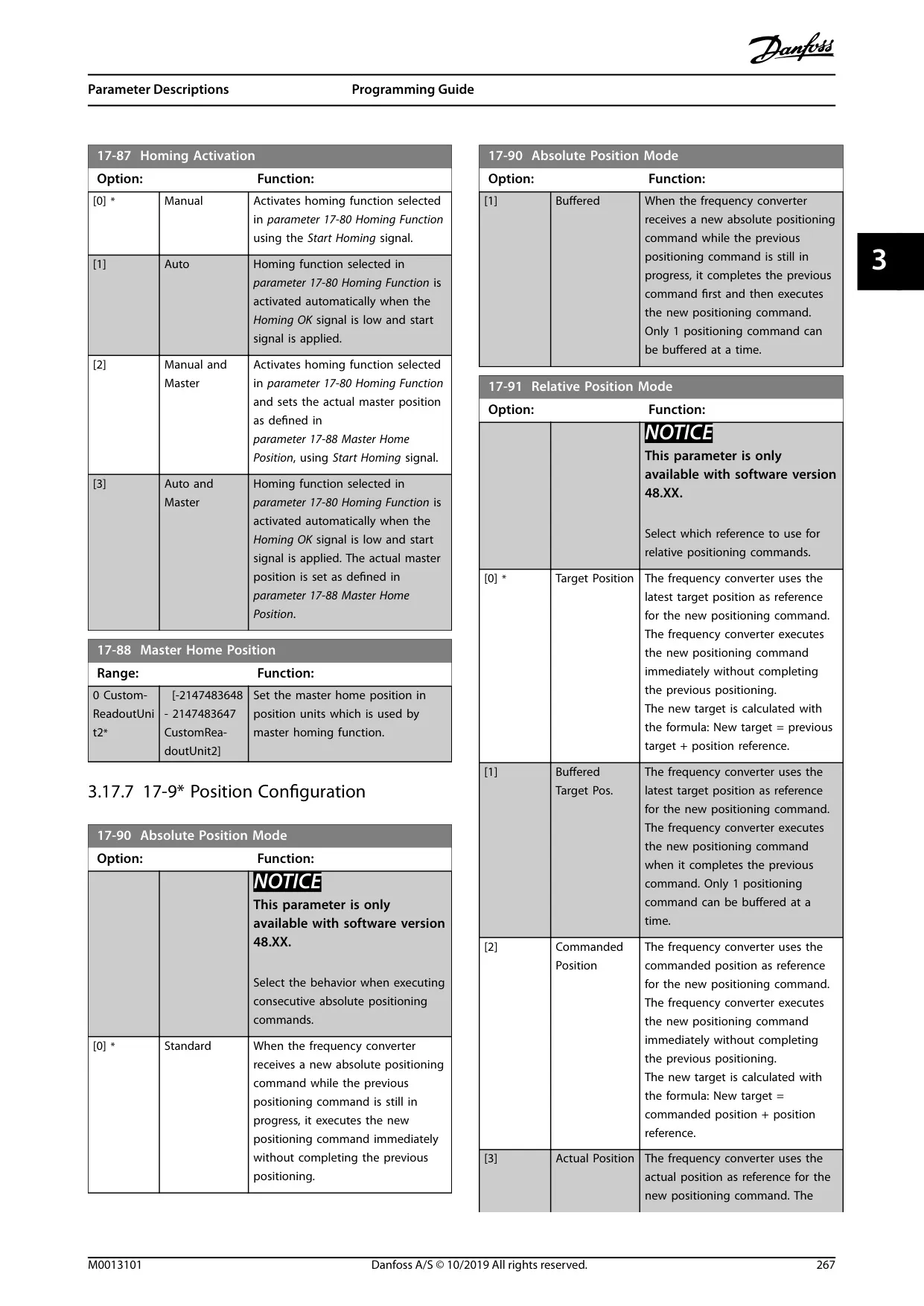
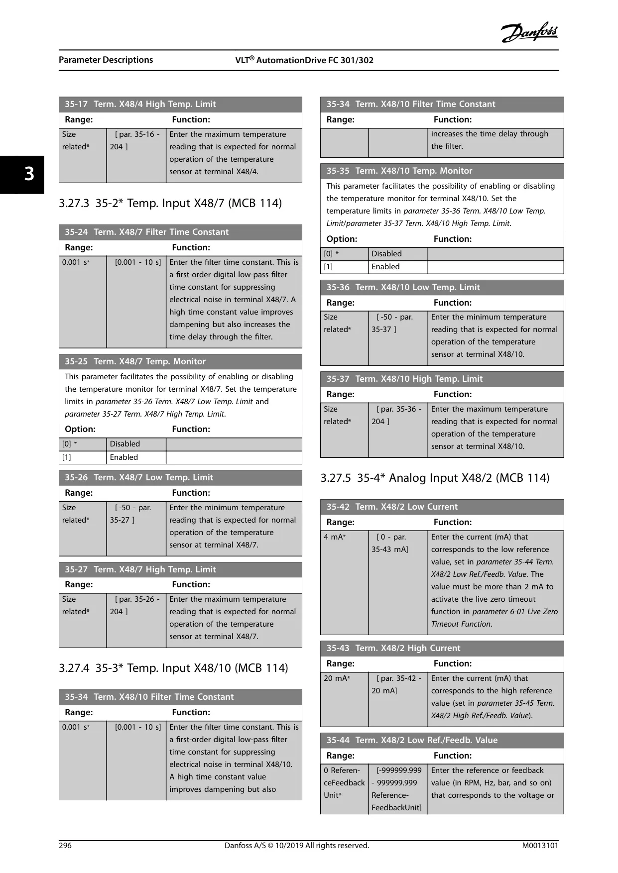
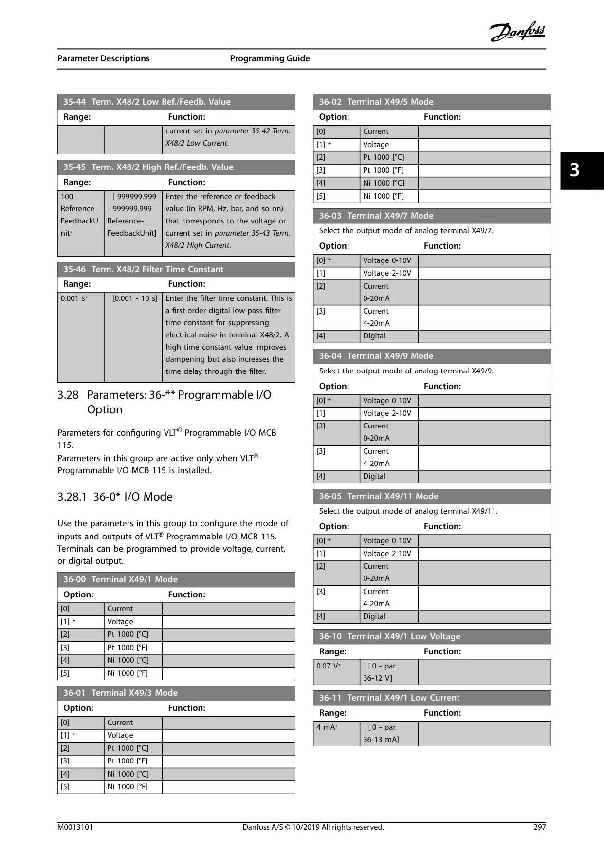
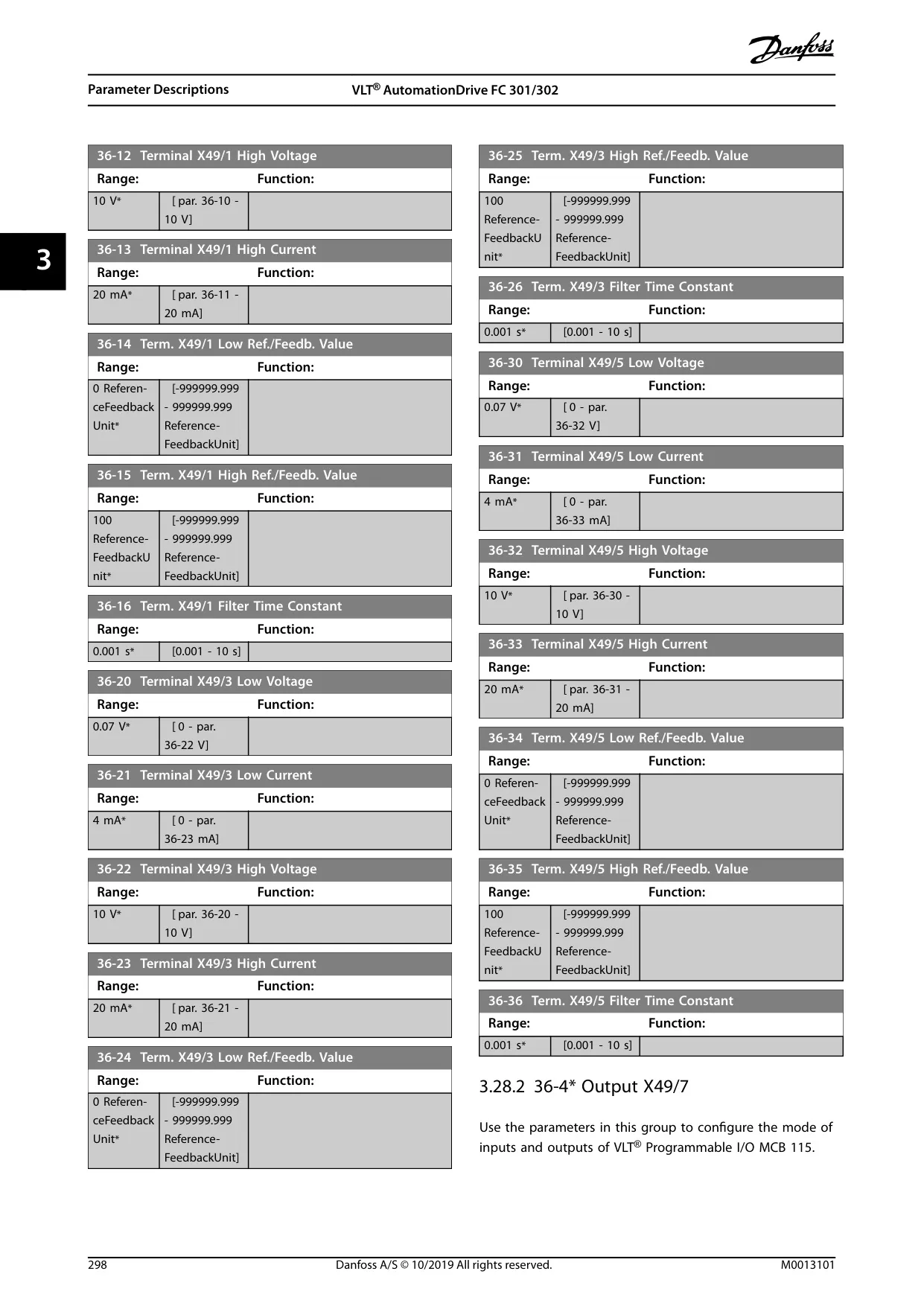
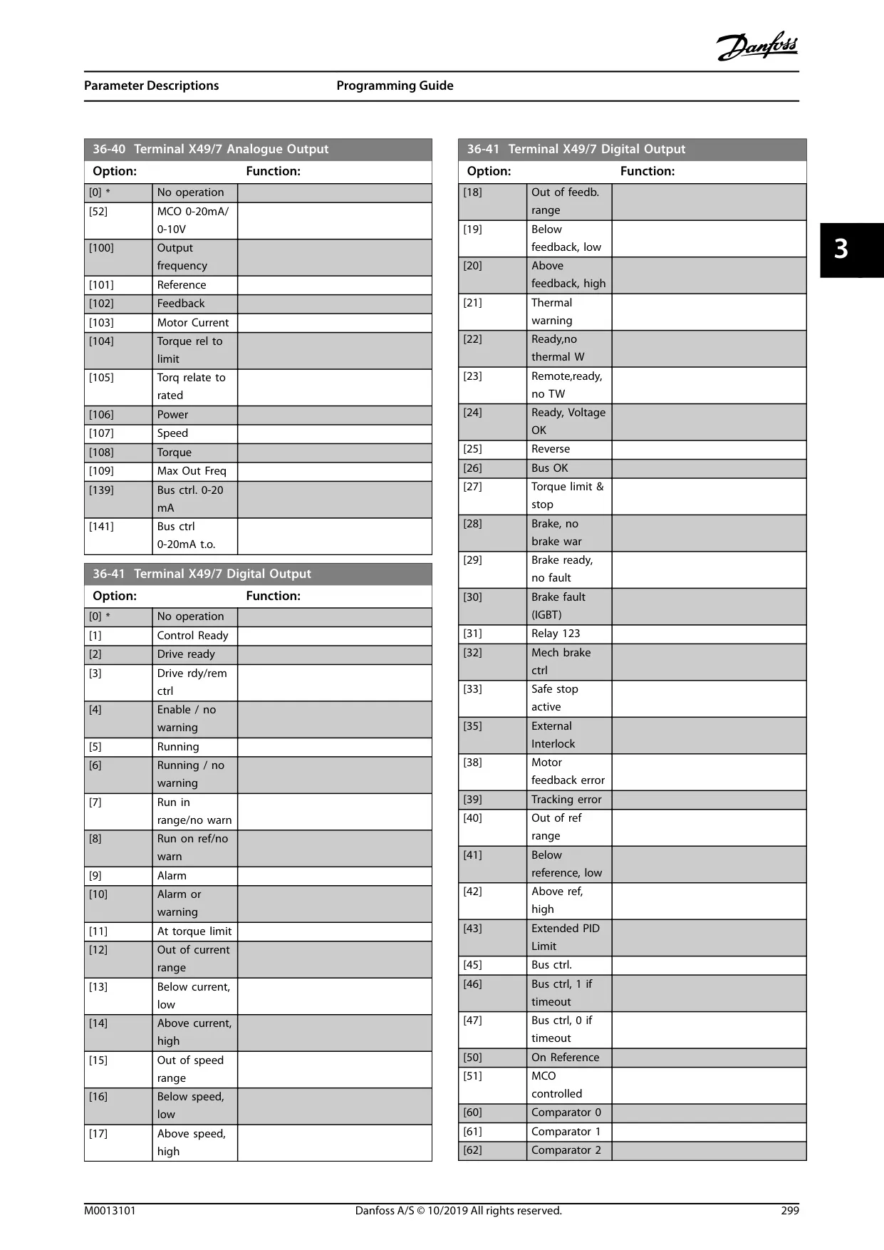
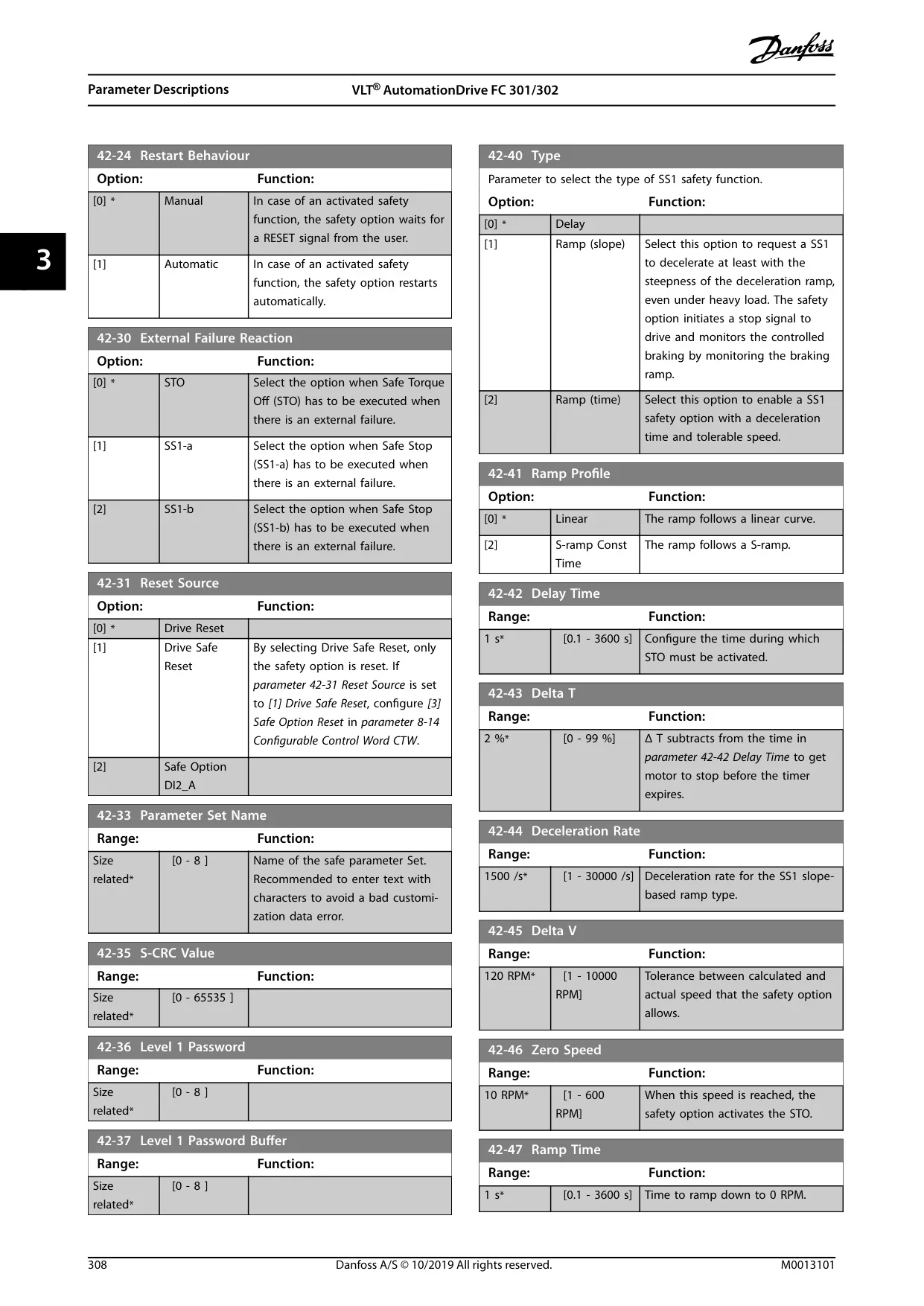
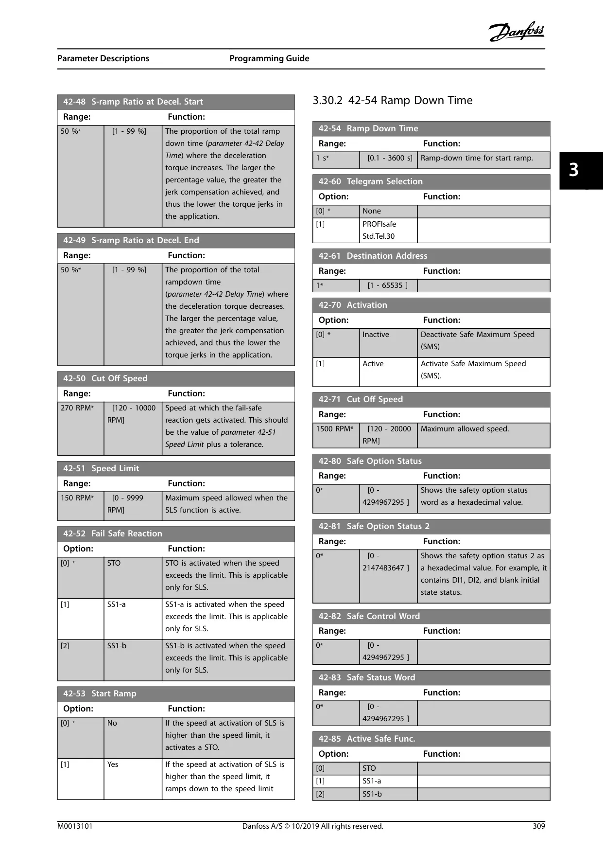
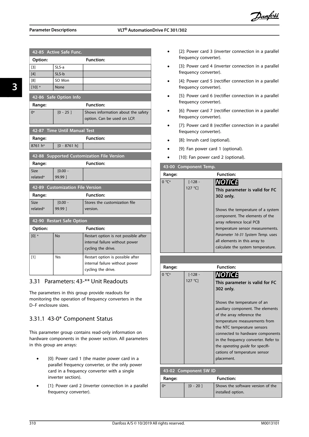
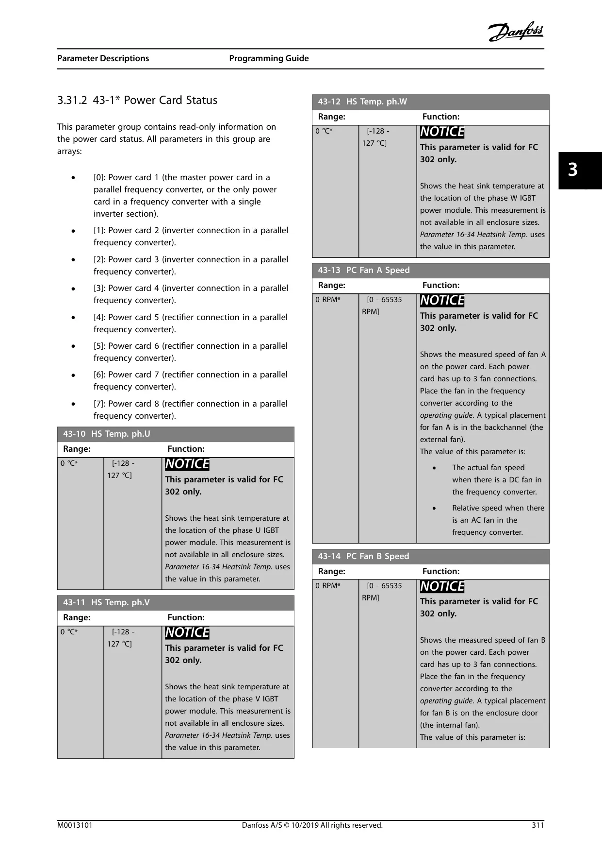
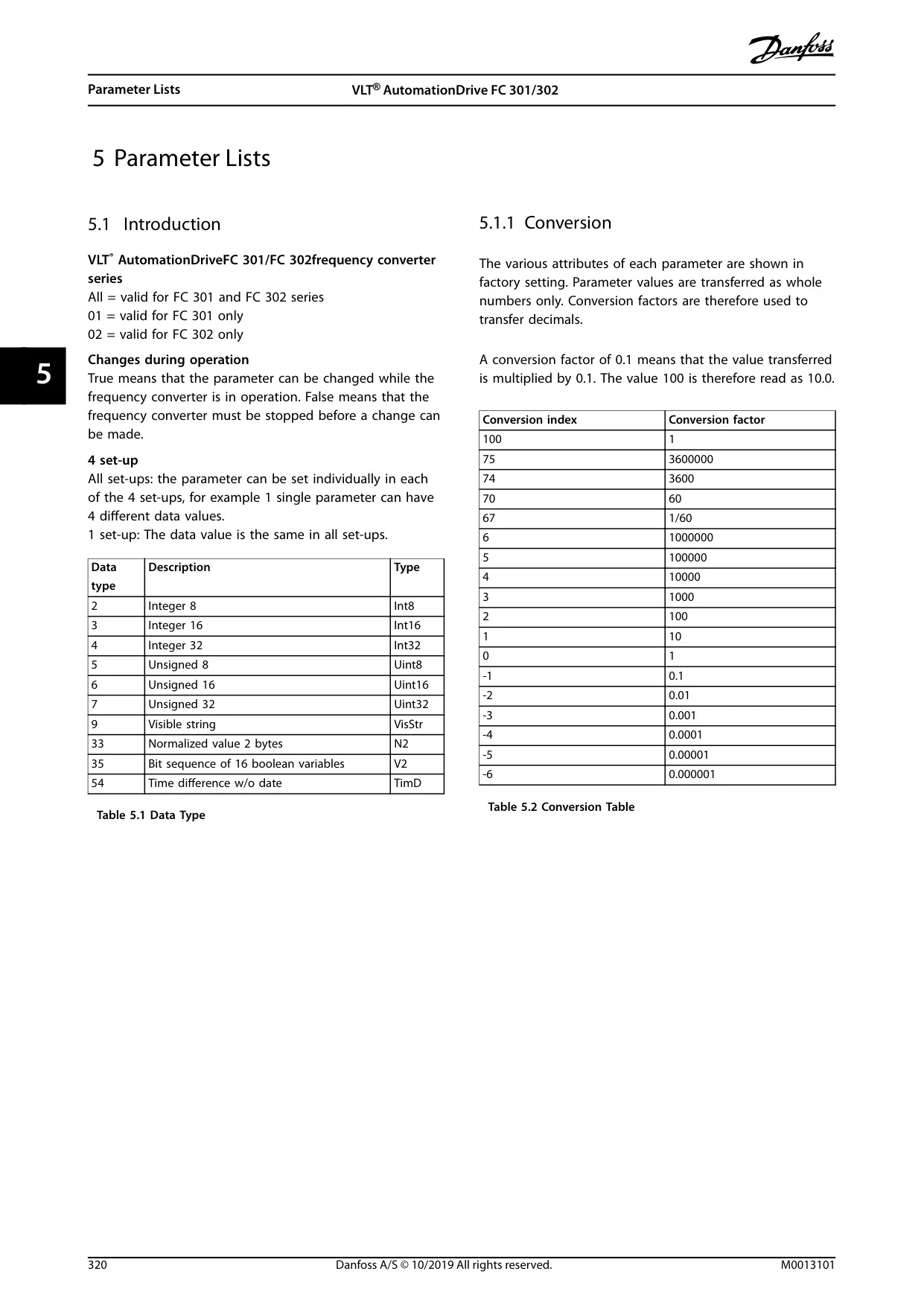
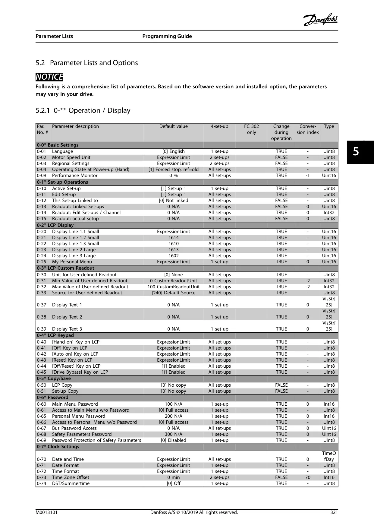
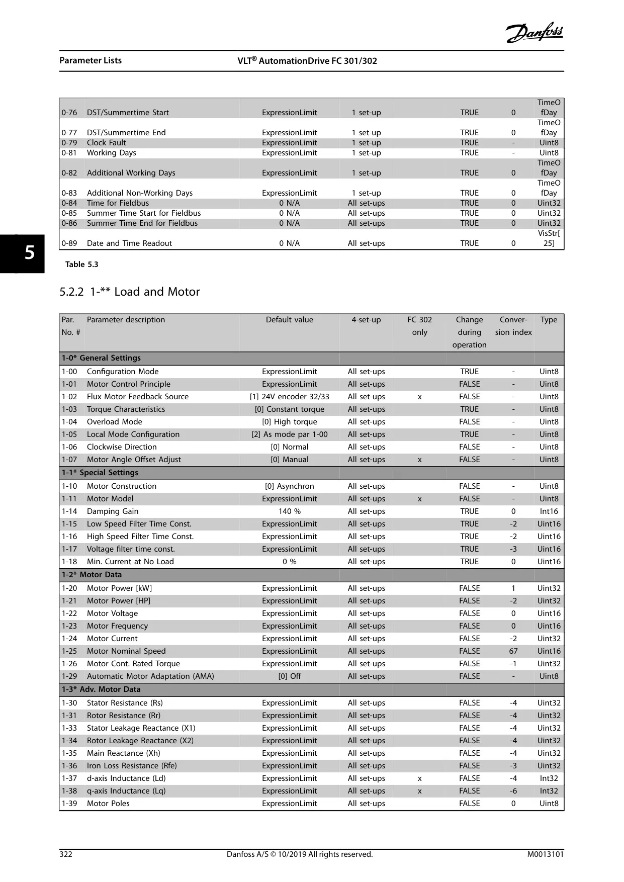
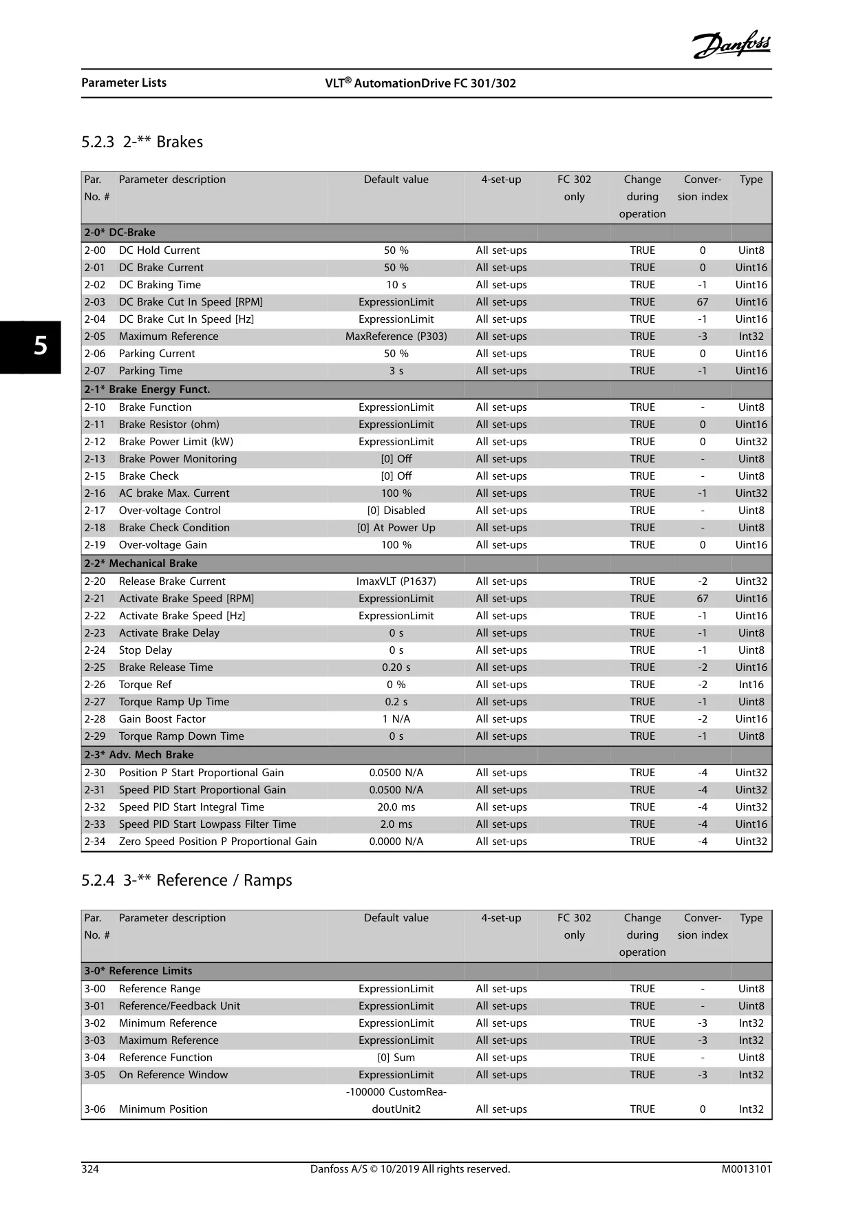
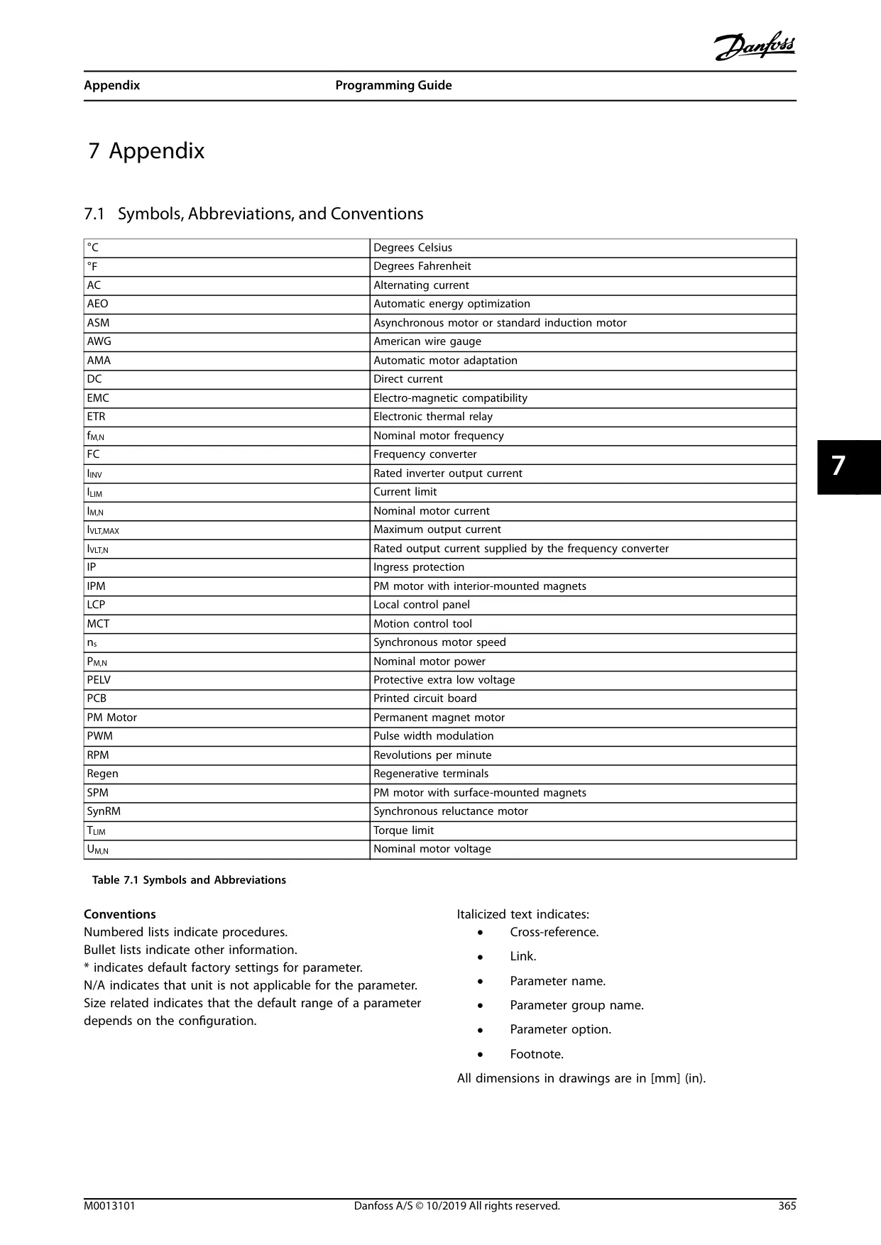
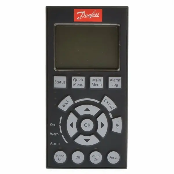
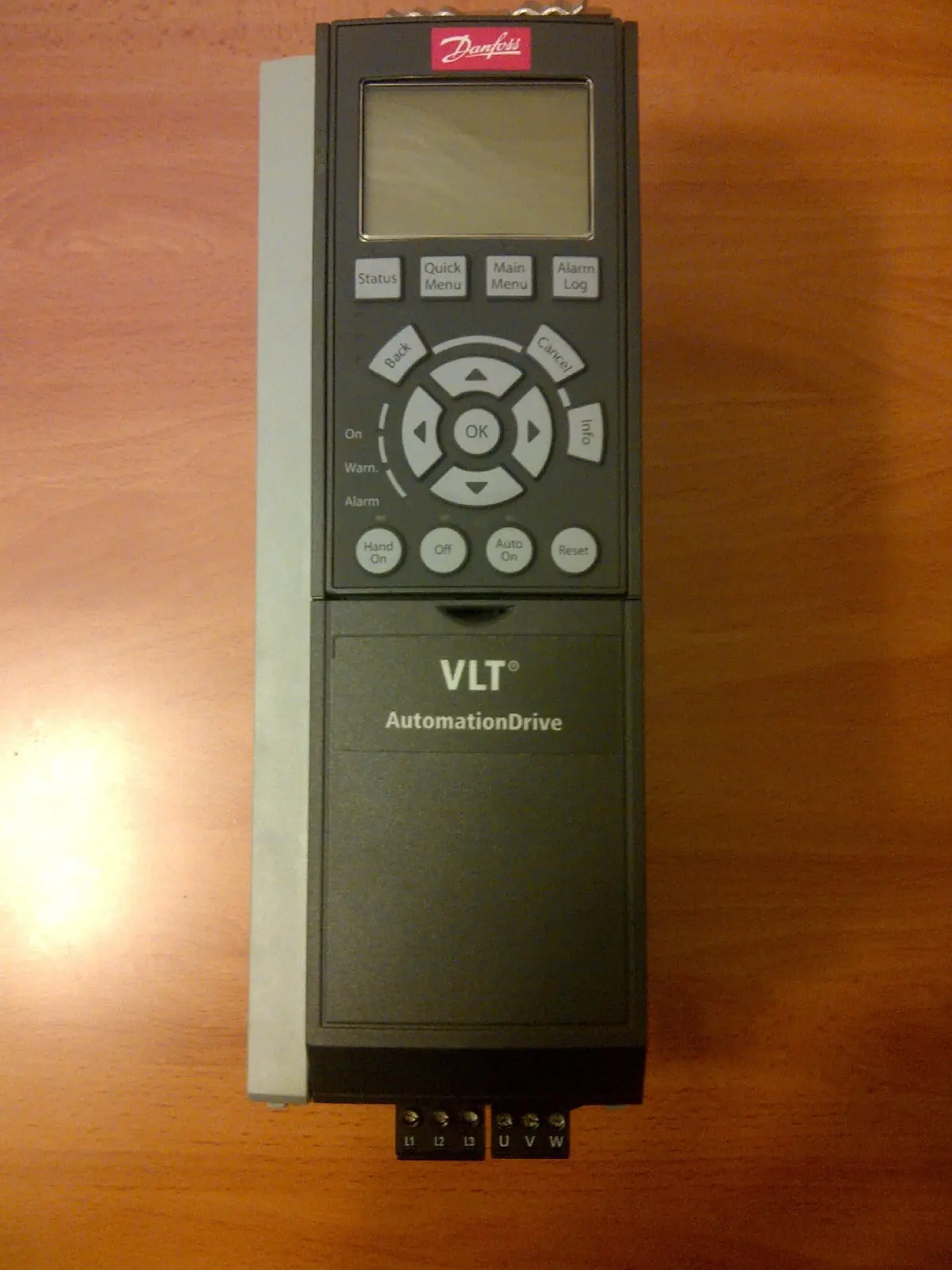
Programming the FC-302 is primarily done via the Graphical Local Control Panel (LCP), featuring a clear display, menu, navigation, and operation keys. The Automatic Motor Adaptation (AMA) function is vital for optimizing dynamic motor performance, by automatically calibrating key motor parameters at standstill. The quick set-up procedure simplifies initial commissioning for various applications.
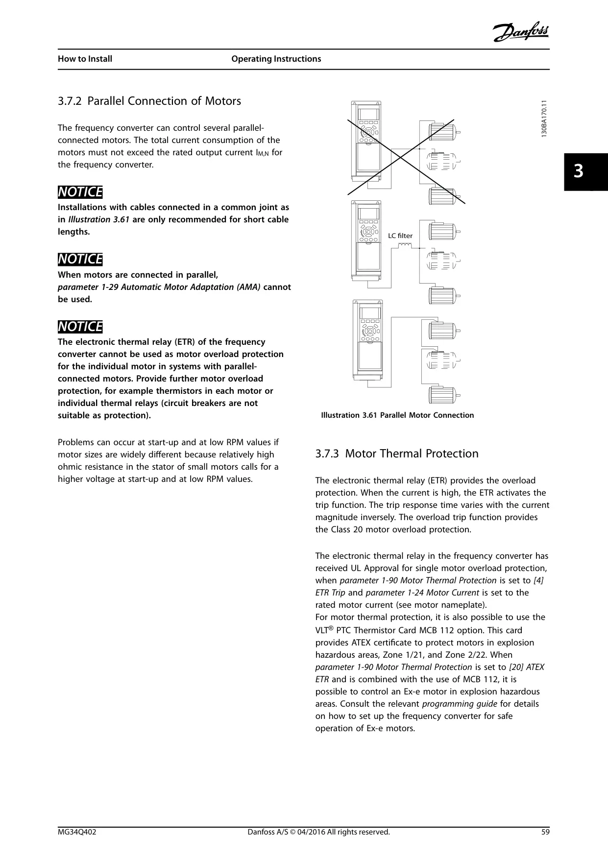
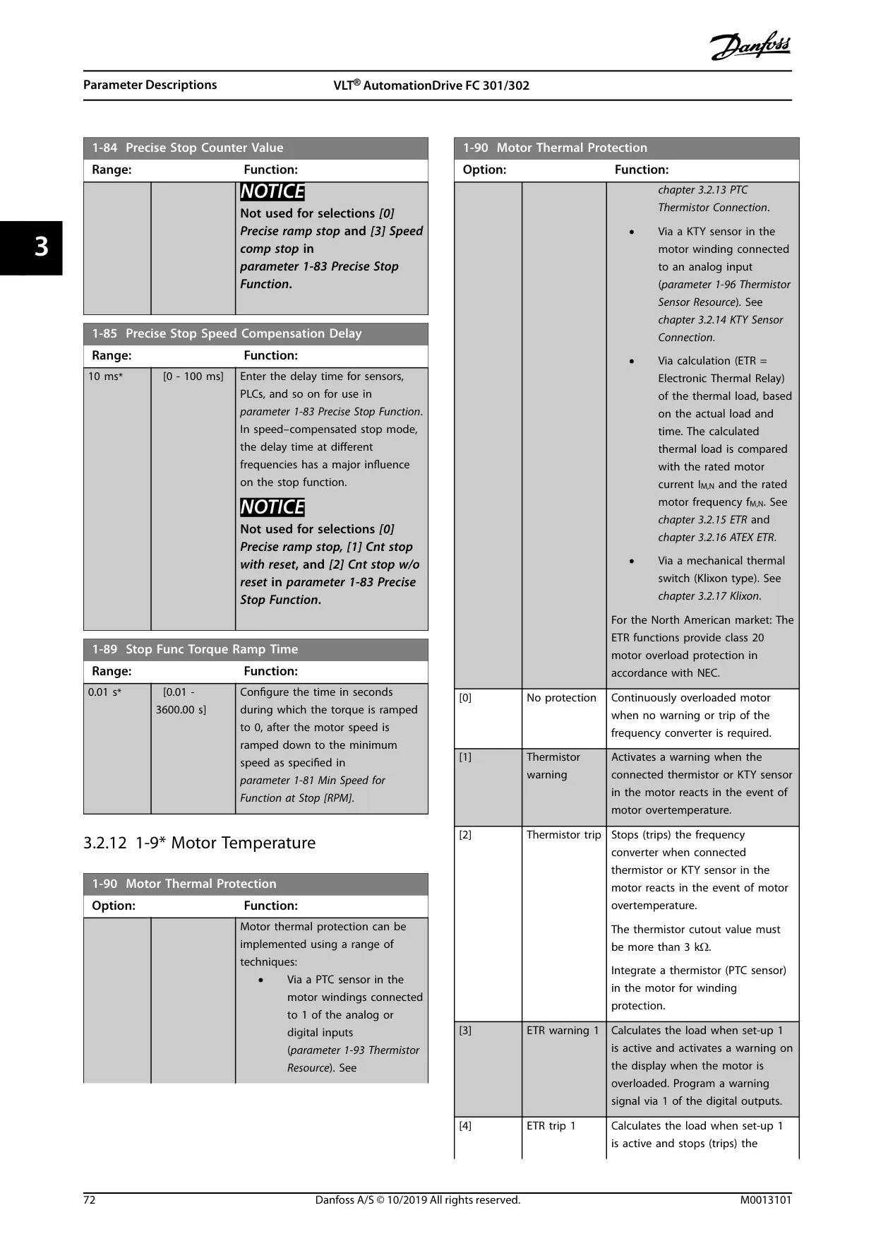
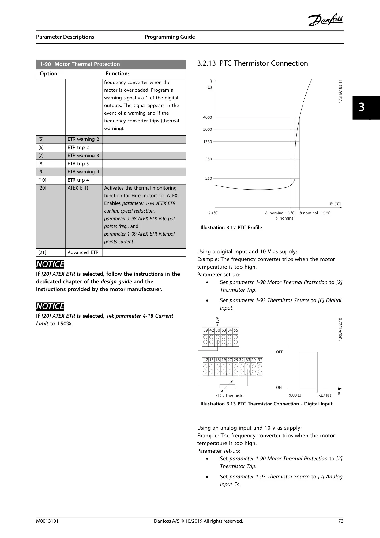
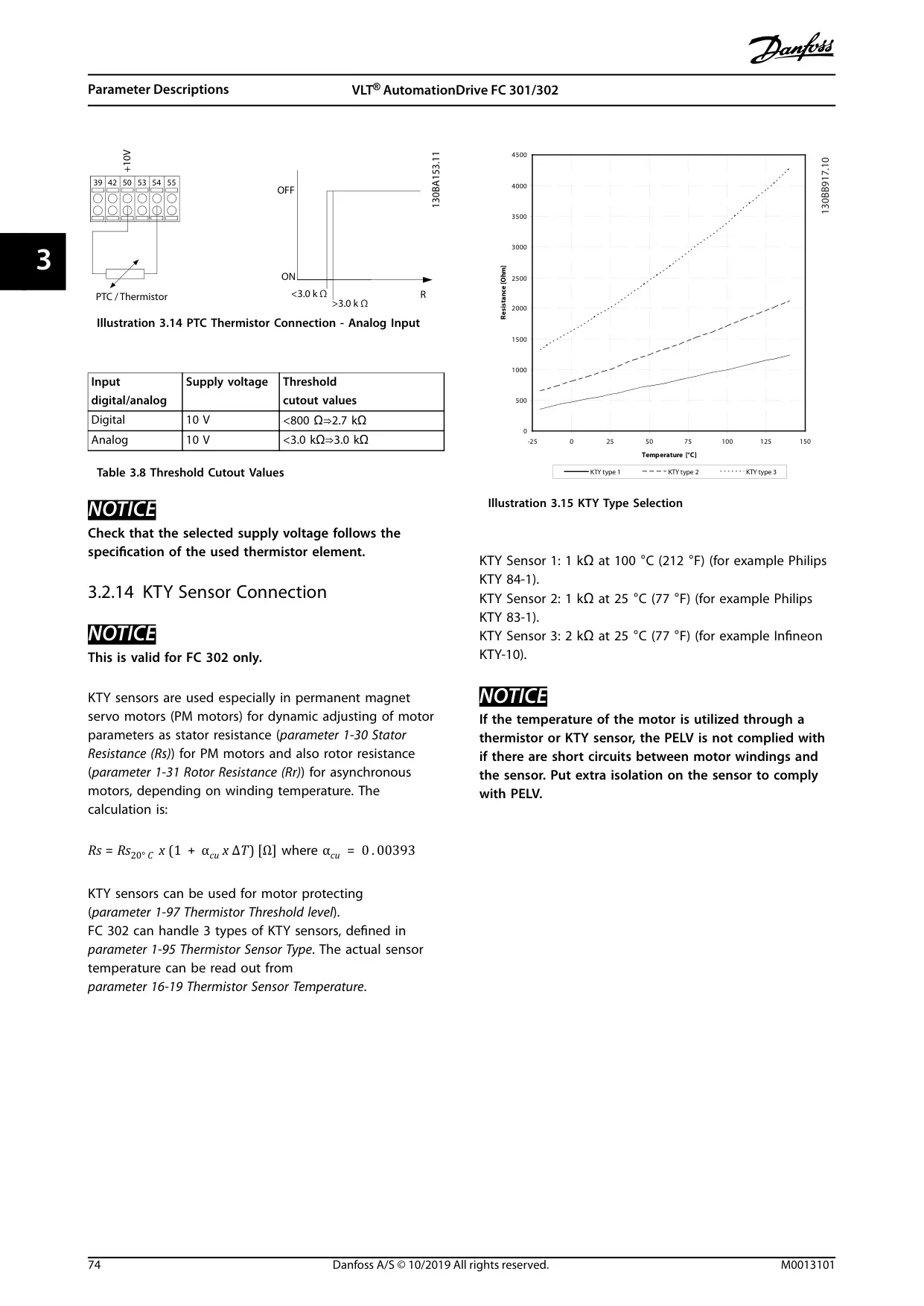
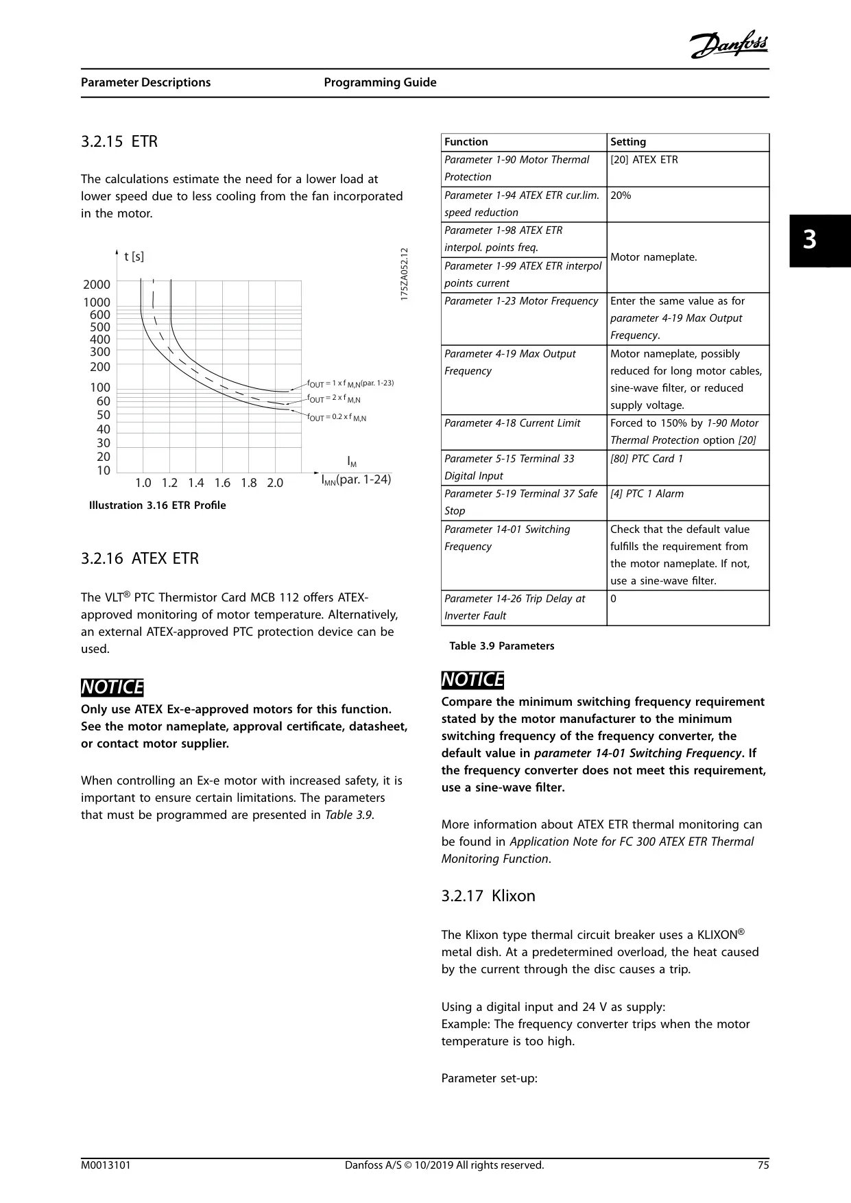
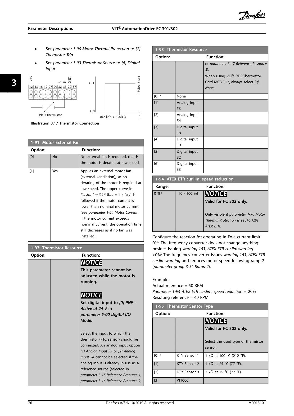
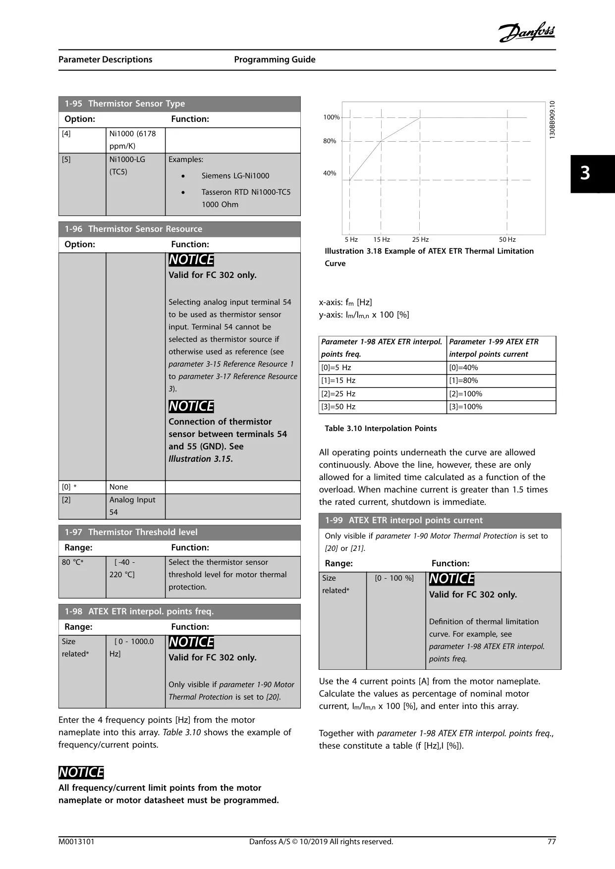
Advanced protection features extend beyond basic overload. The Electronic Thermal Relay (ETR) offers UL-approved single motor overload protection. The drive also supports the VLT PTC Thermistor Card MCB 112 for ATEX-certified motor protection in hazardous areas. Furthermore, sophisticated control capabilities like mechanical brake control and options for parallel connection of motors enhance versatility.
Frequently Asked Questions (FAQs)
Can't find the answer you need? Here are some frequently asked questions about the Danfoss FC-302 Variable Frequency Drive, and we answer them below.