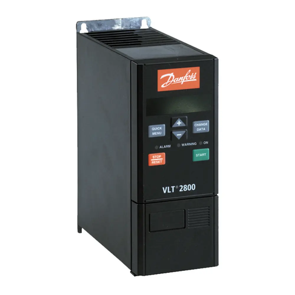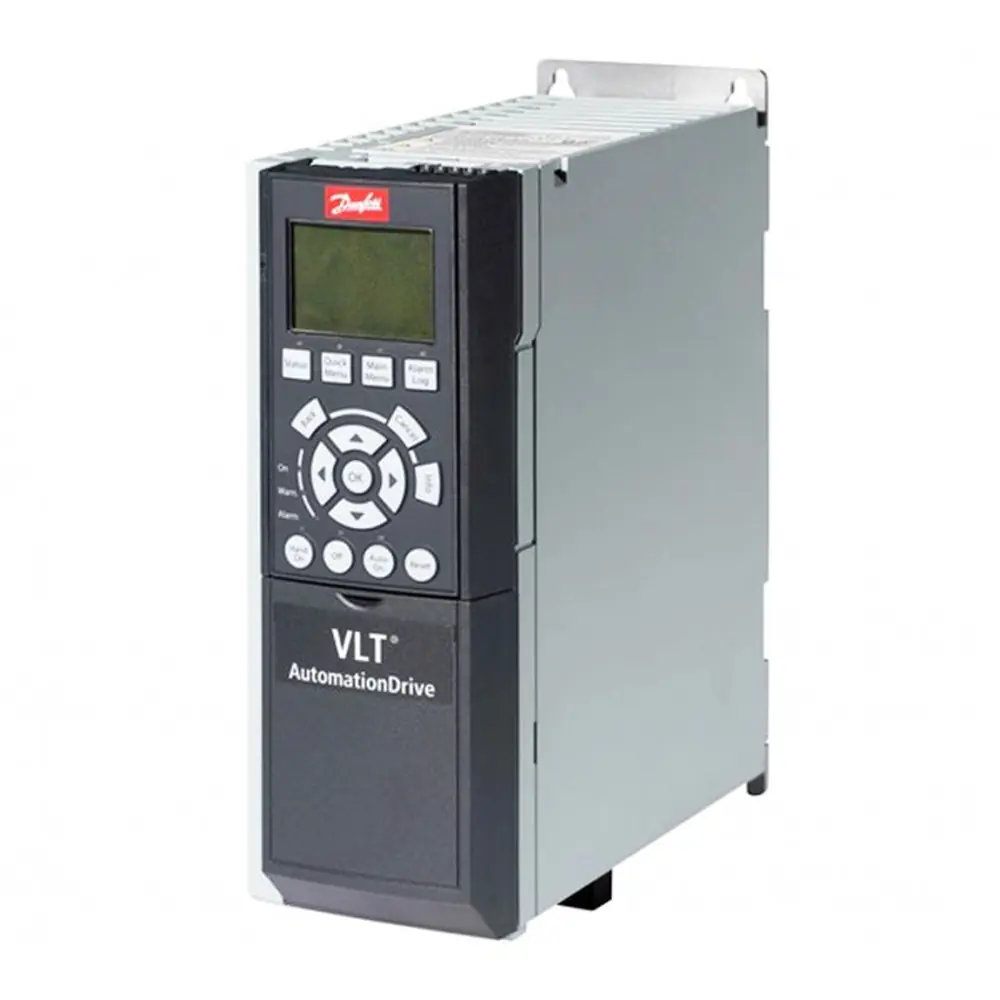
Danfoss VLT 5000 Variable Frequency Drive Instruction Manual
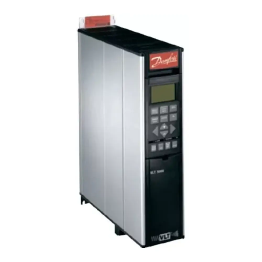
Danfoss VLT 5000 Variable Frequency Drive
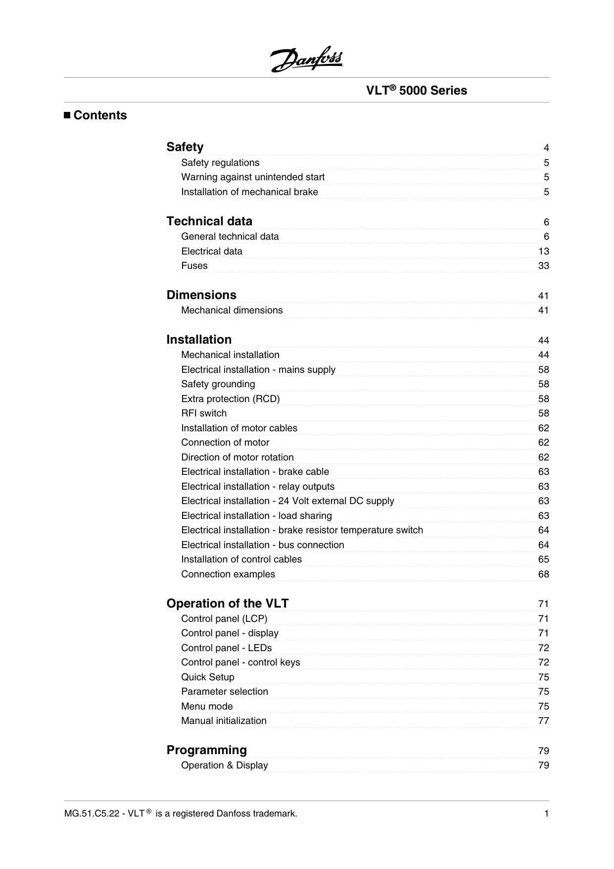
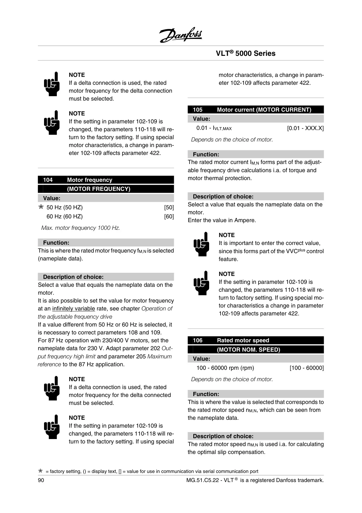
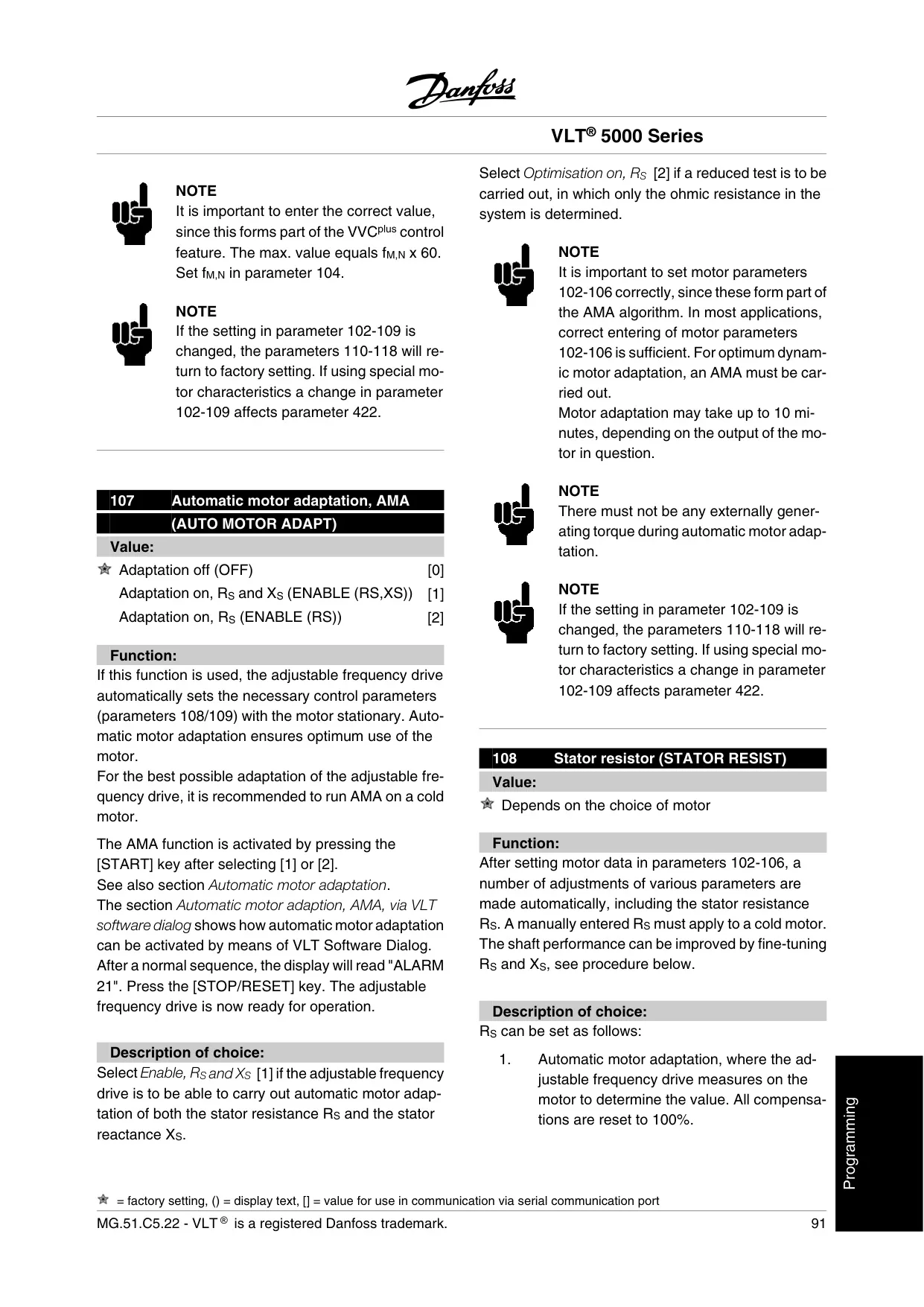
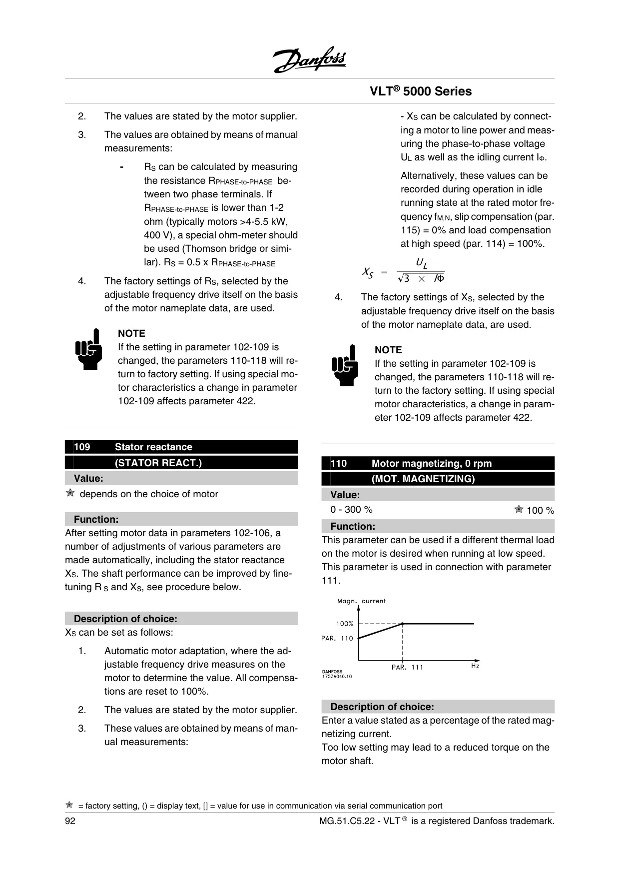
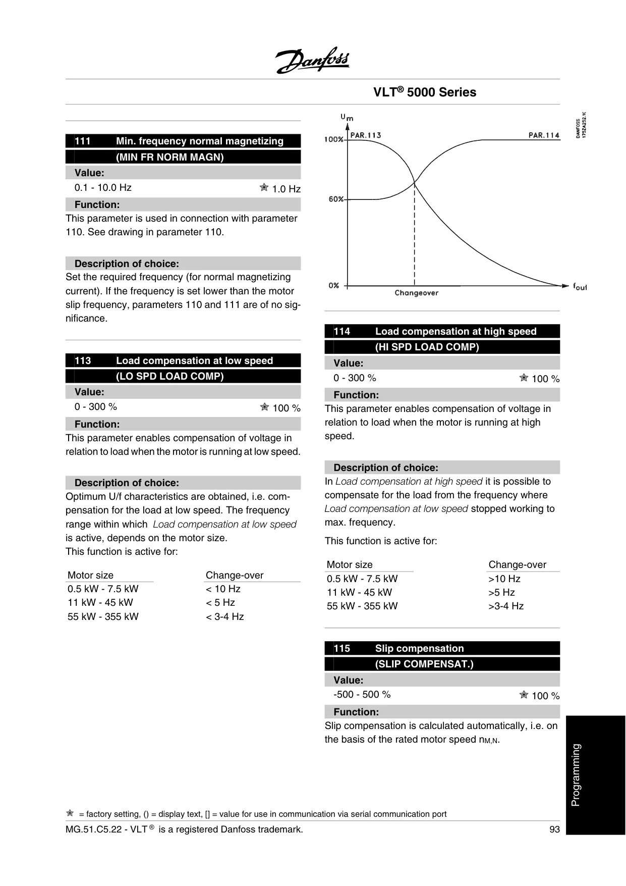
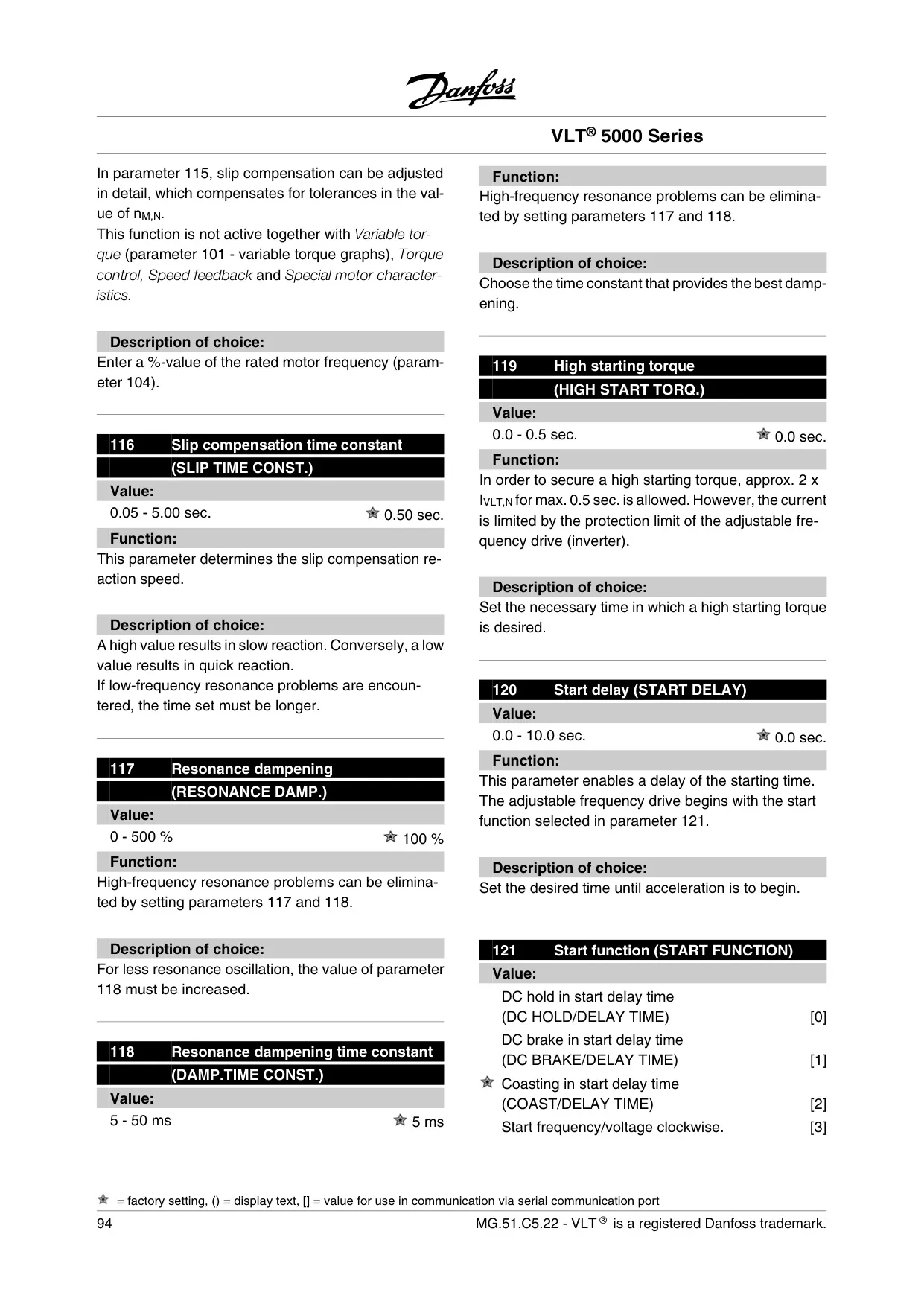
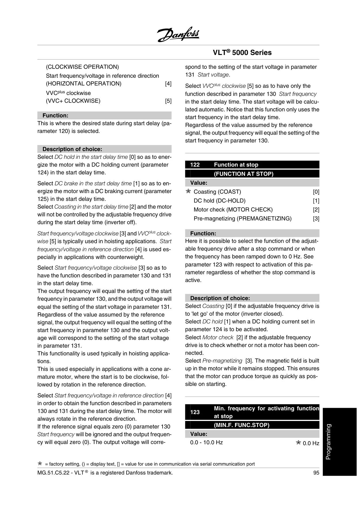
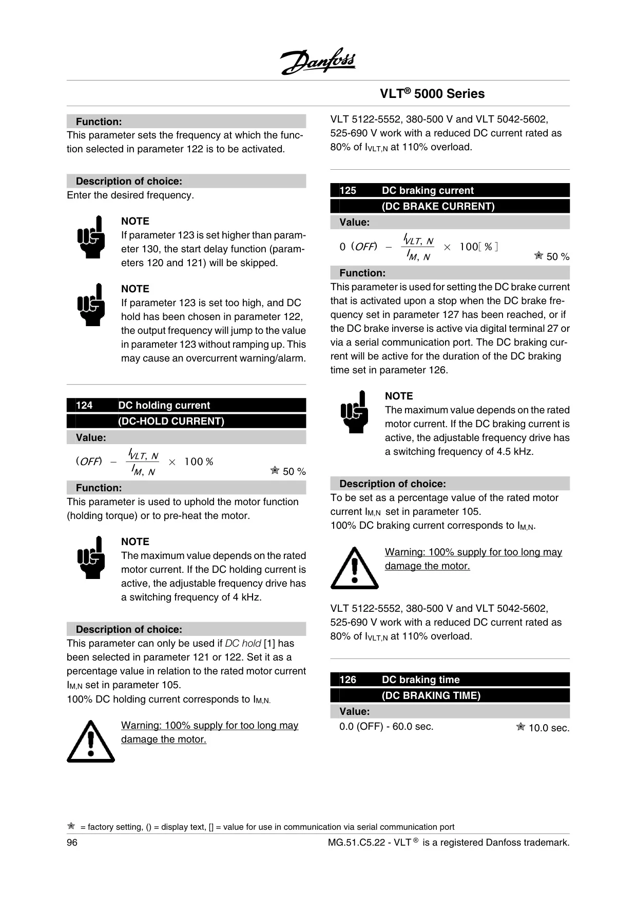
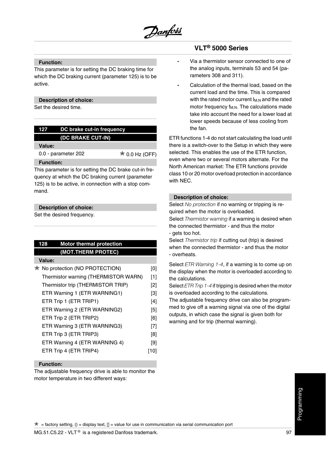
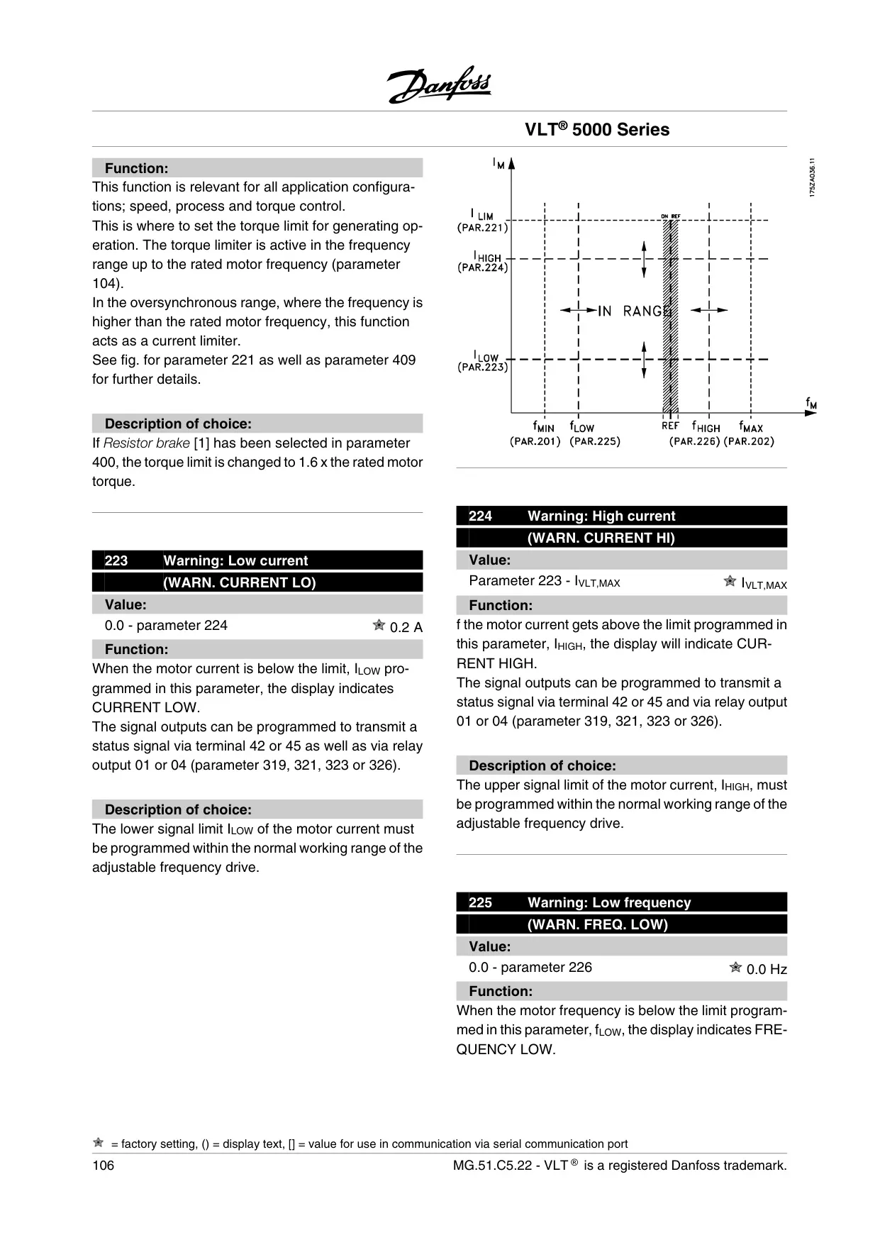
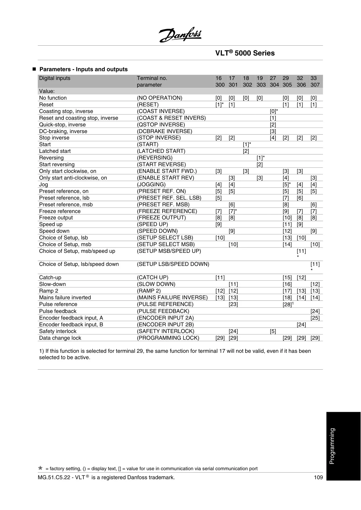
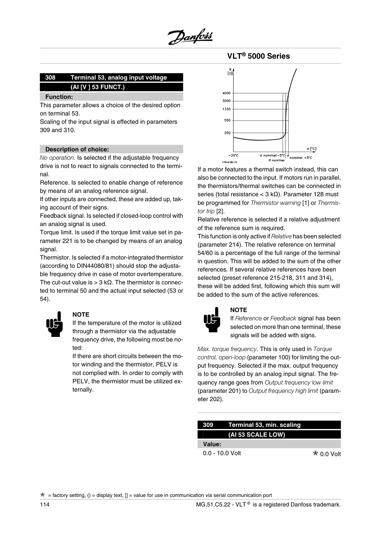
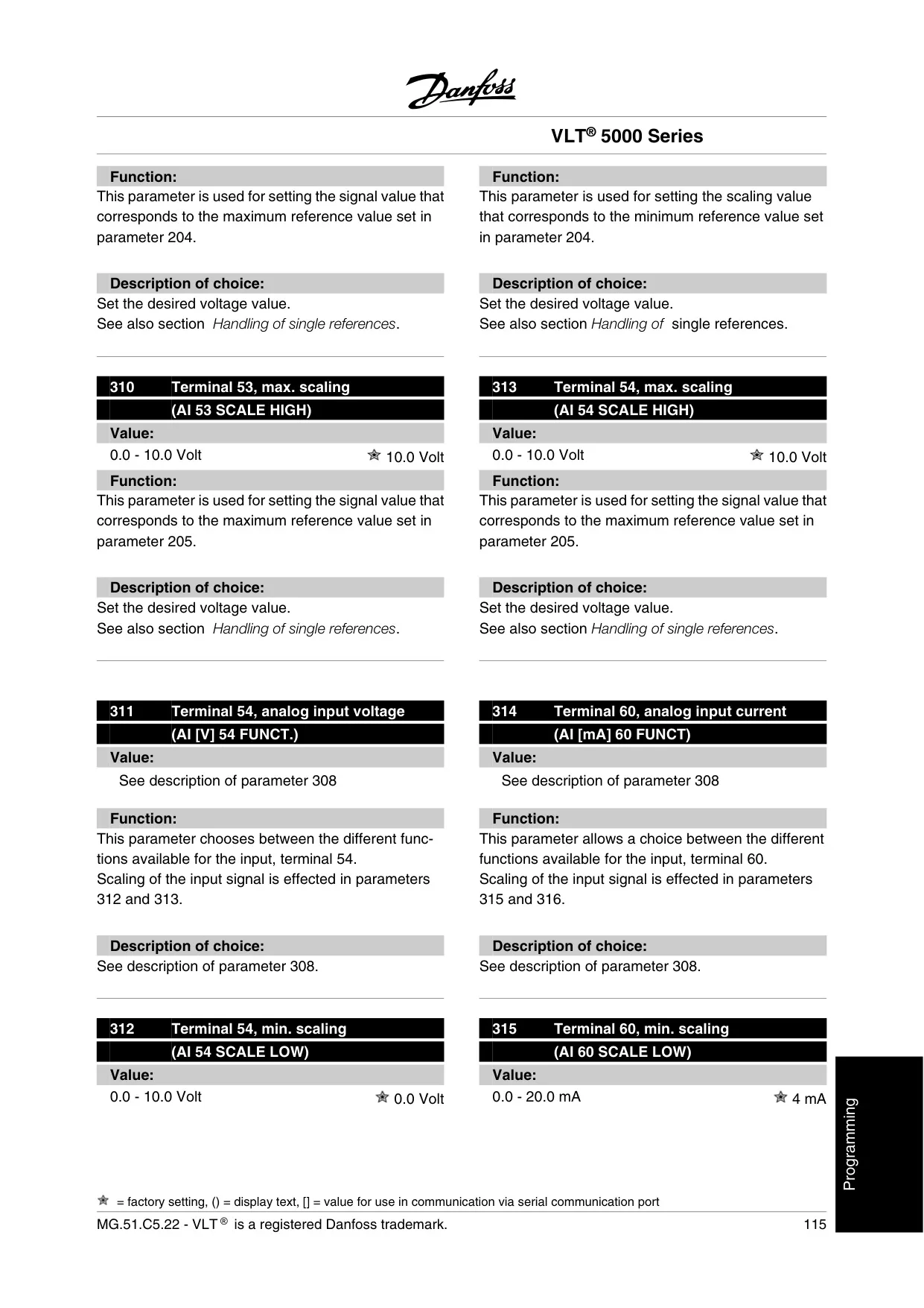
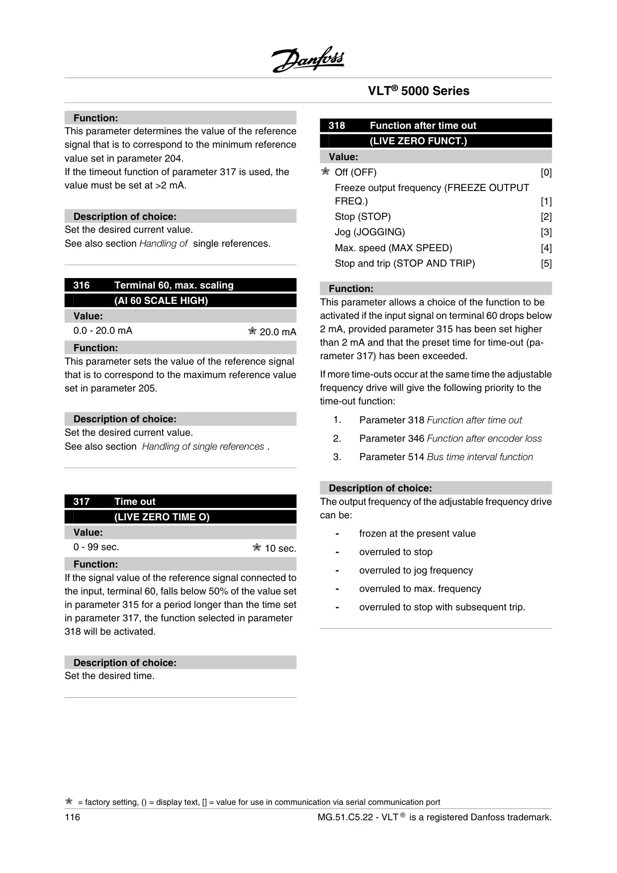
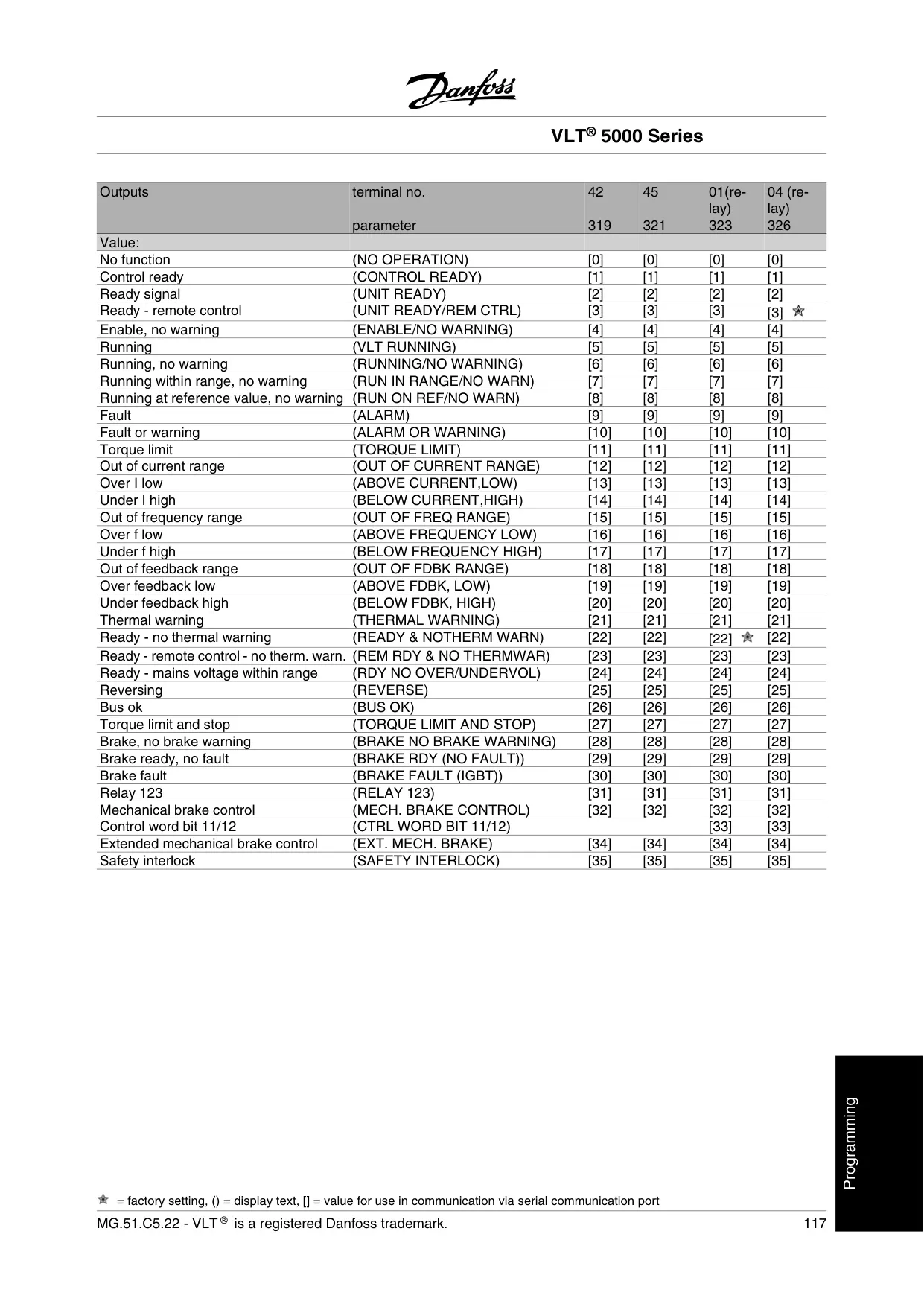
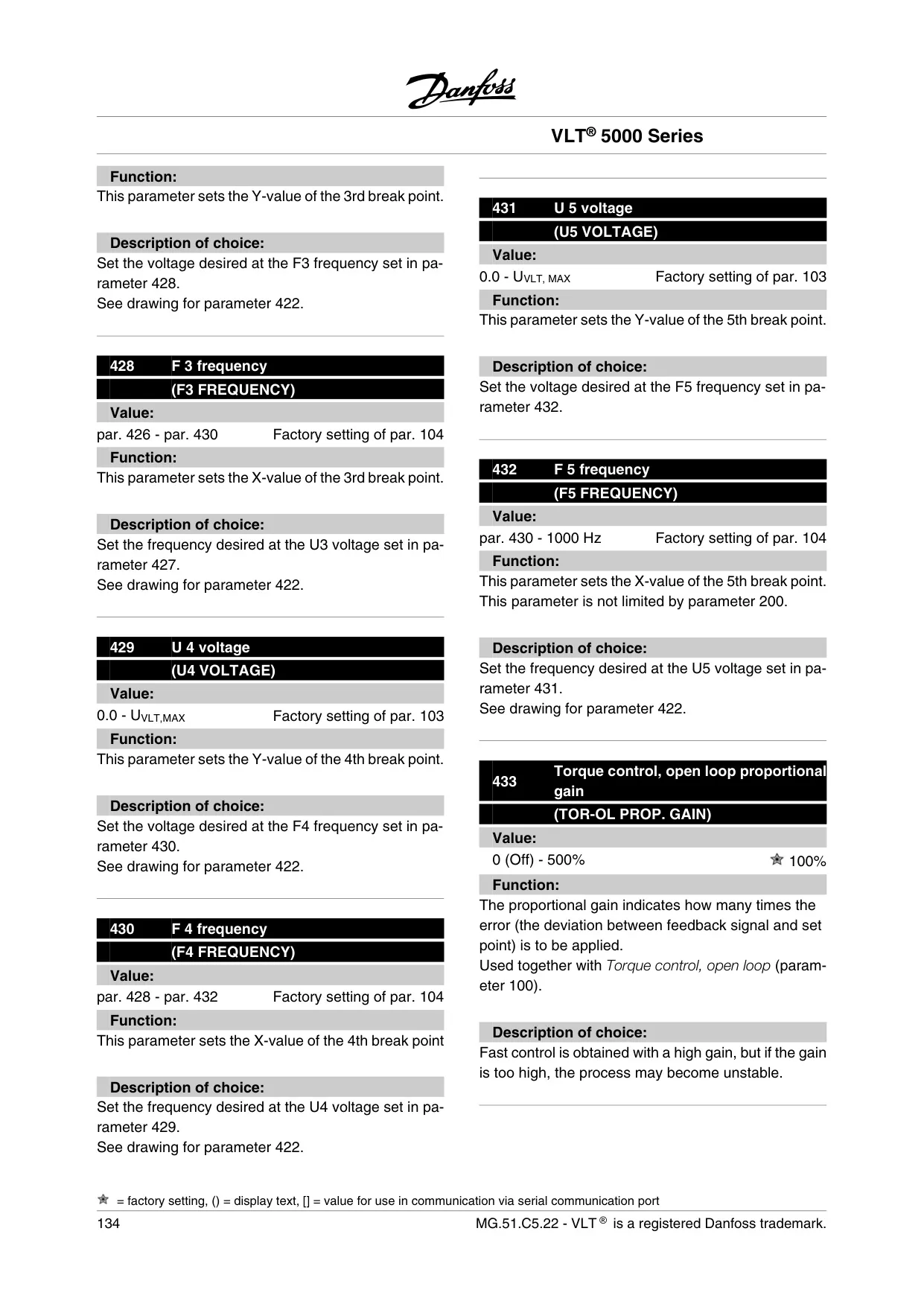
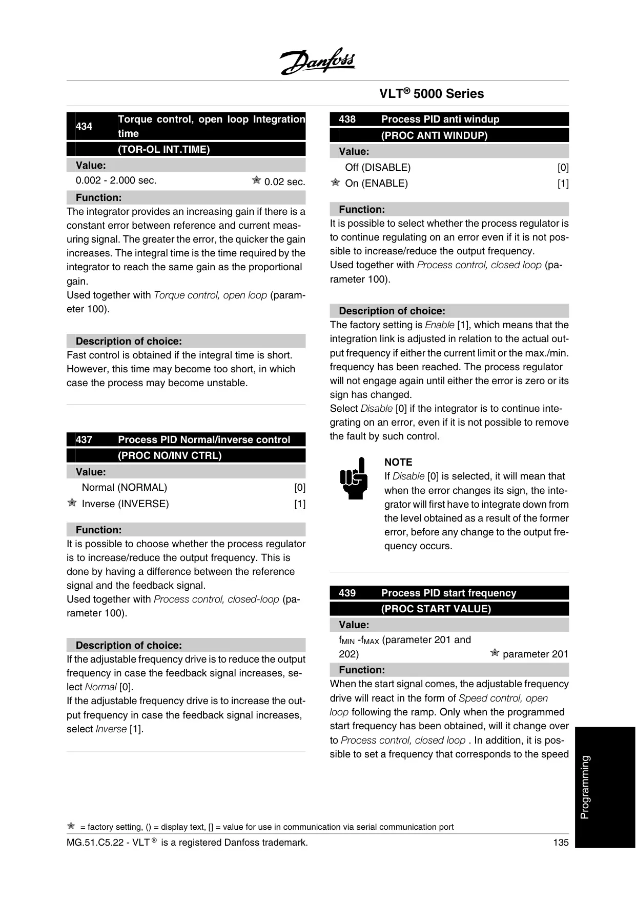
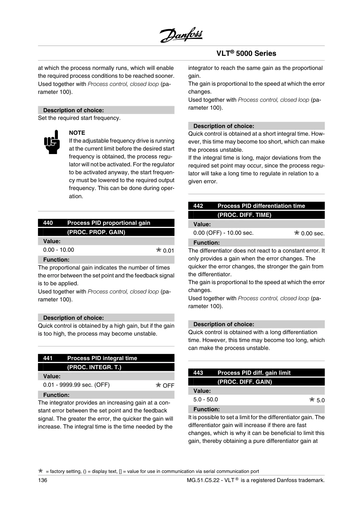
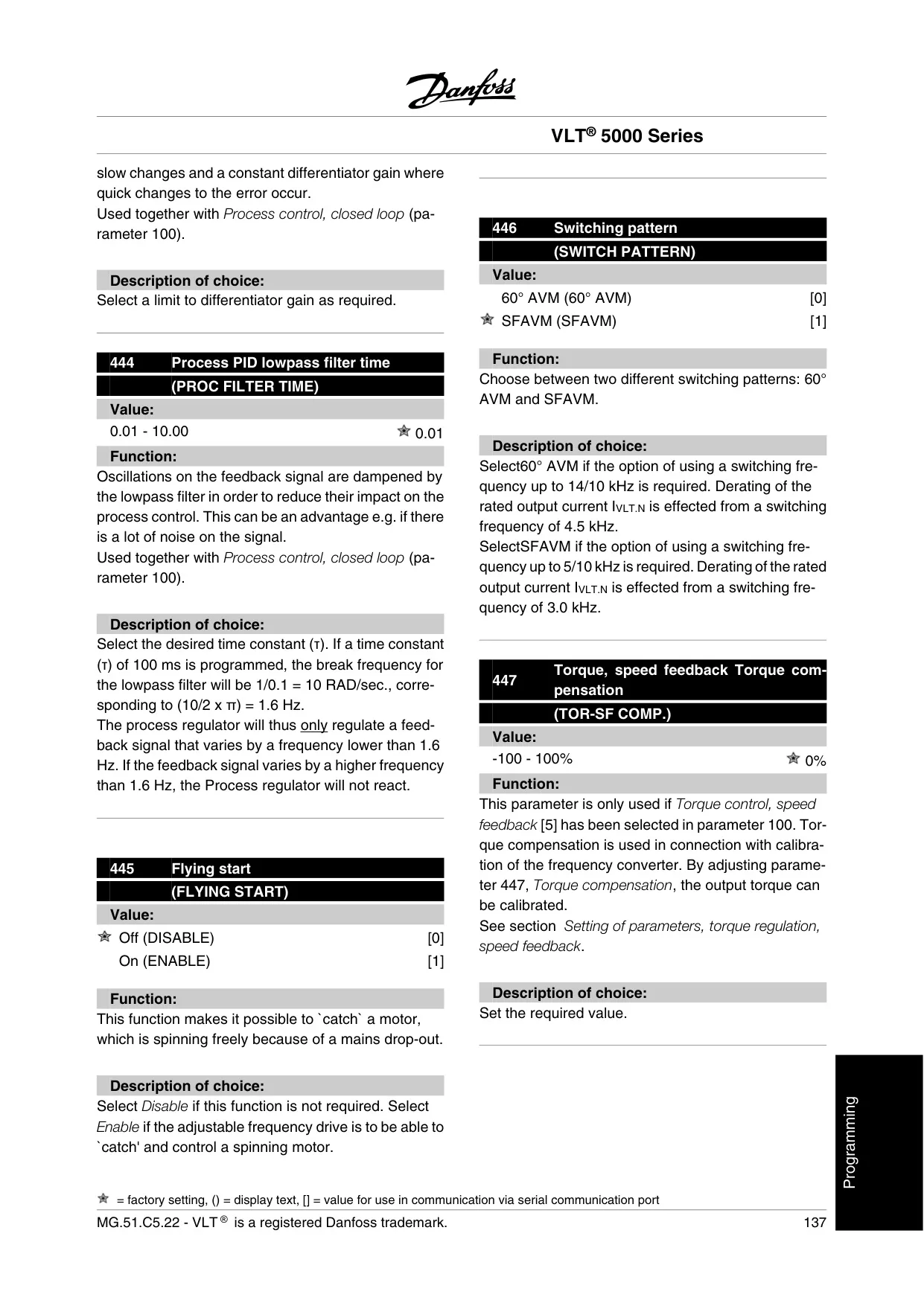
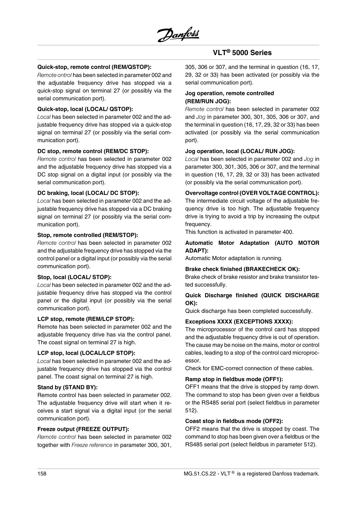
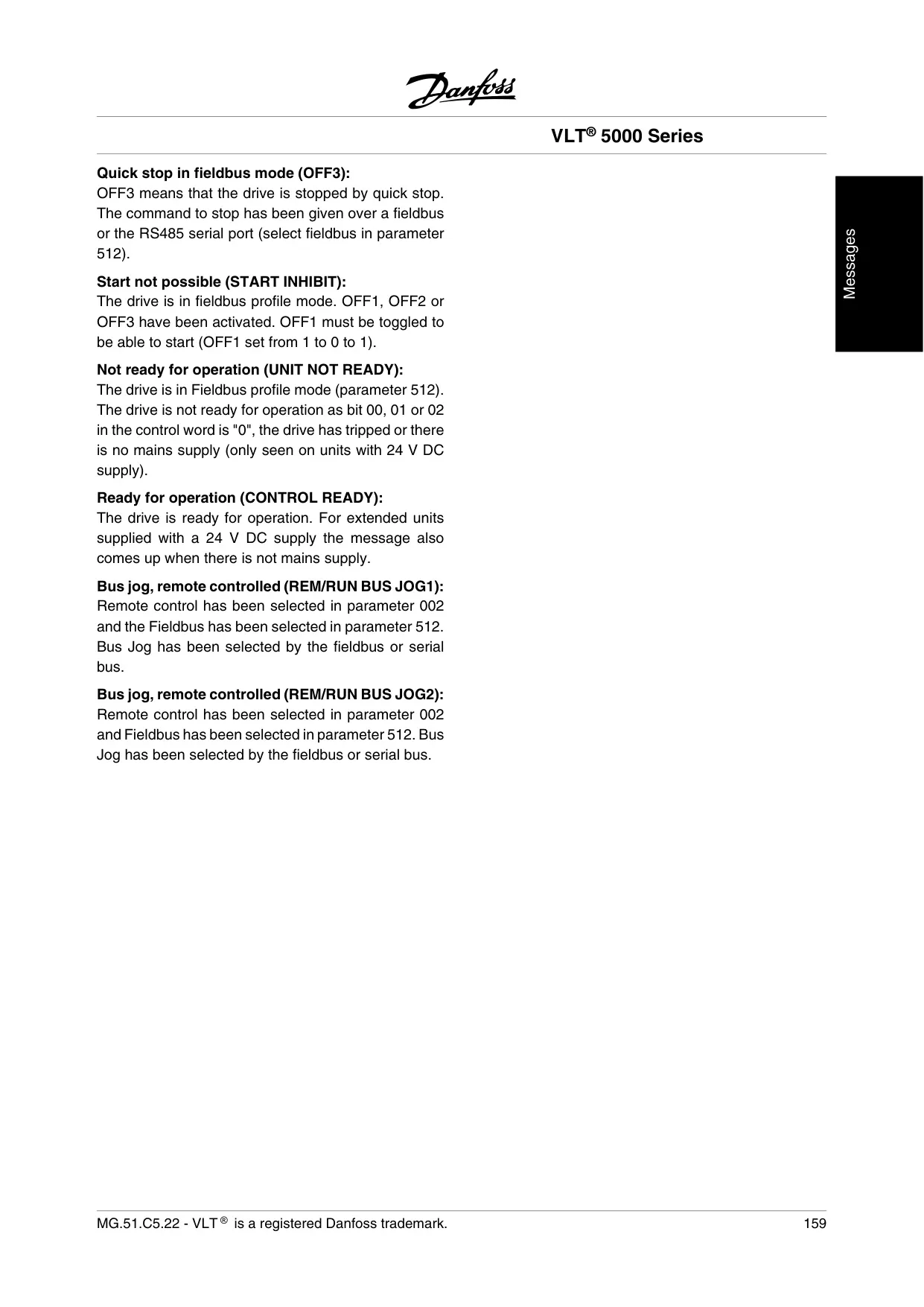
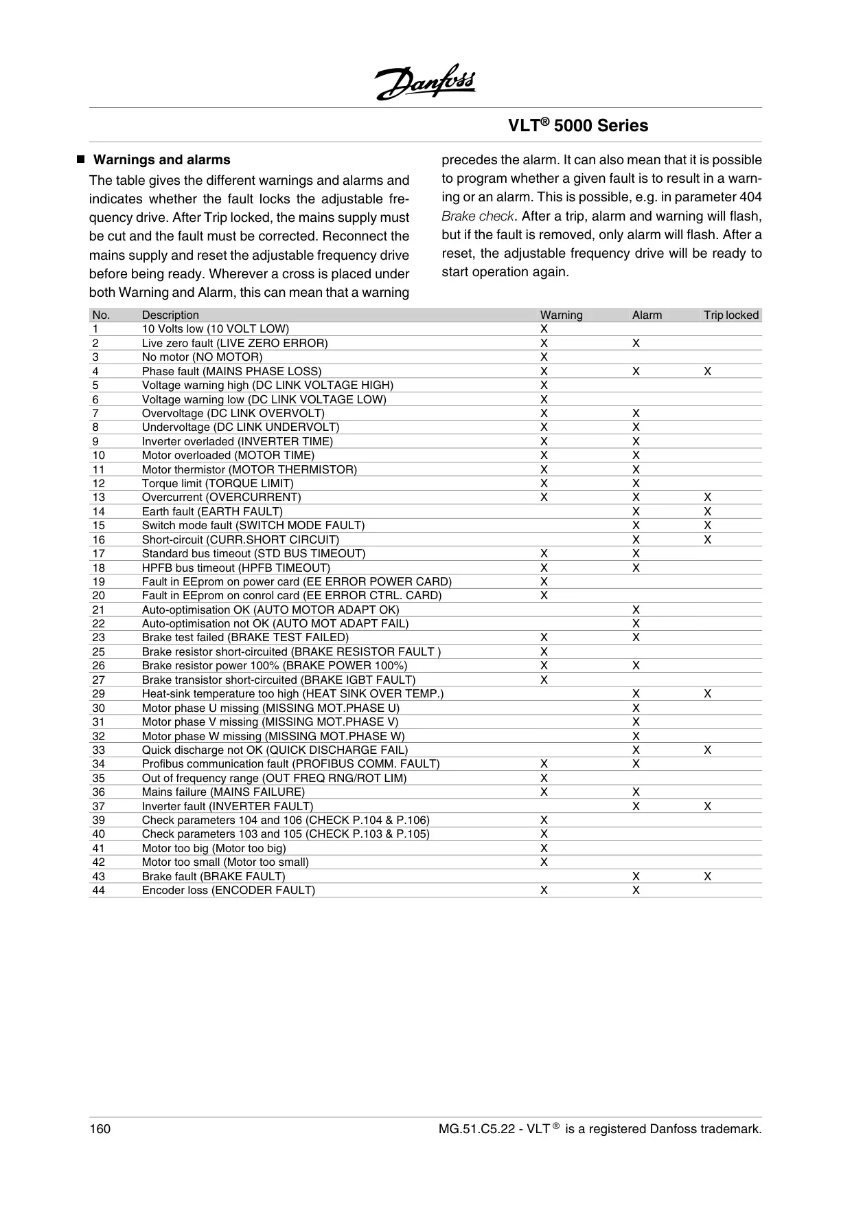
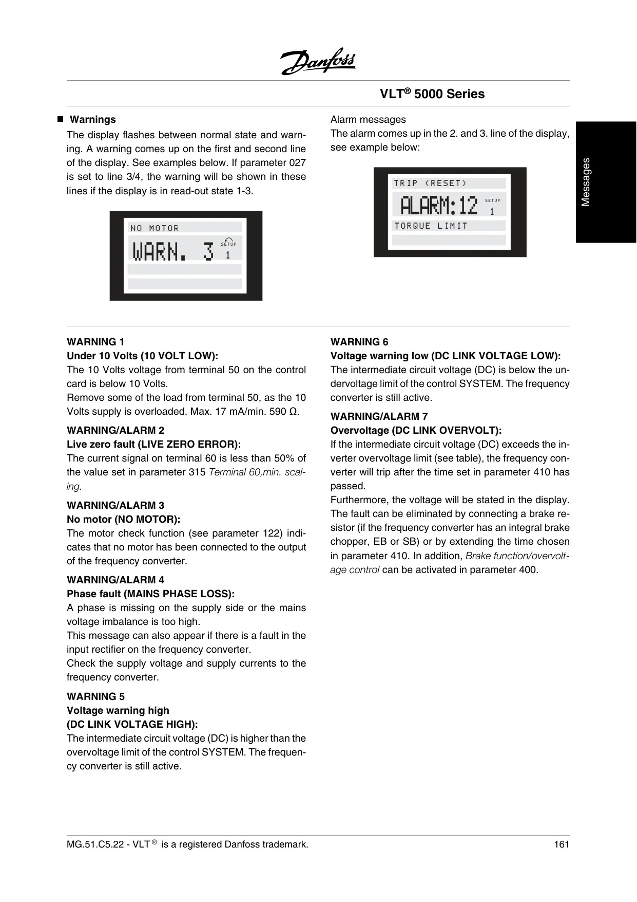
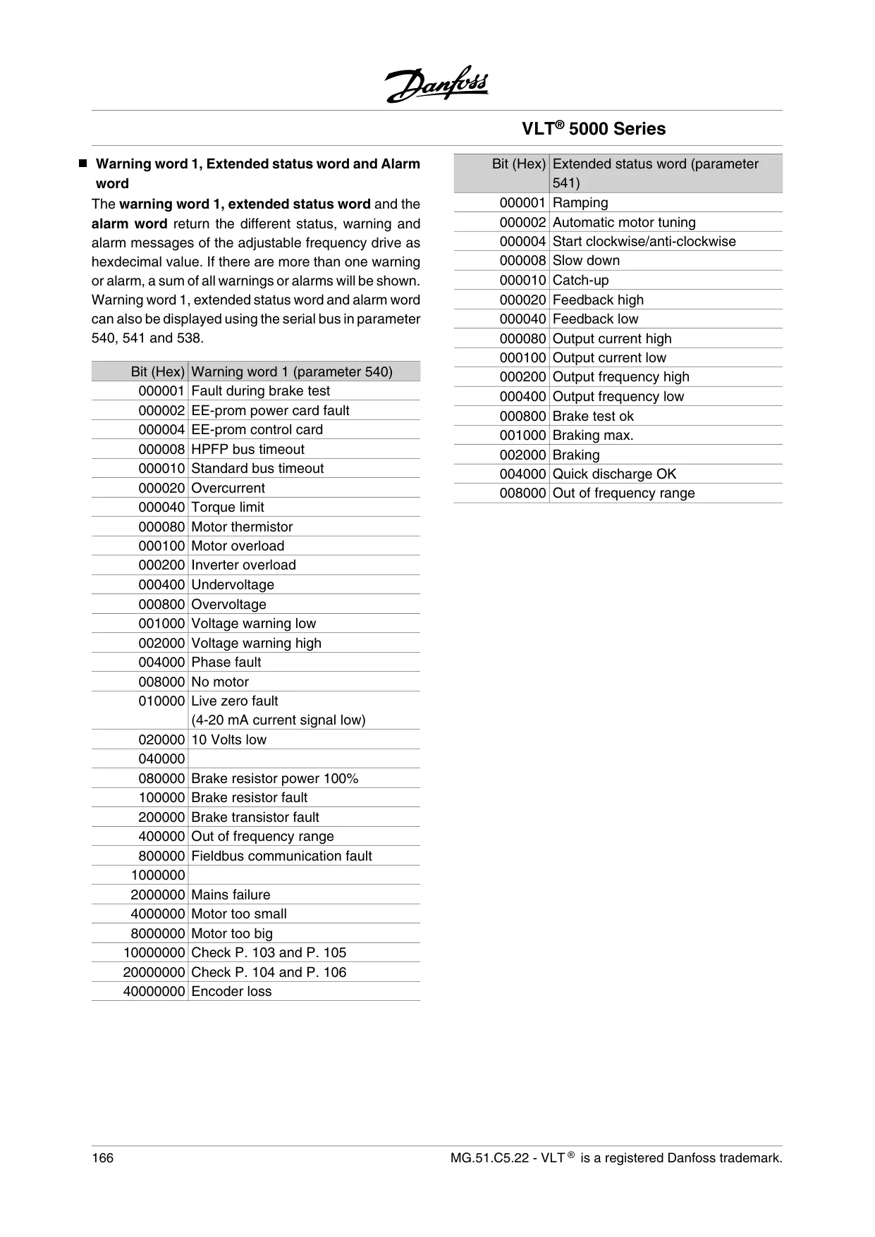
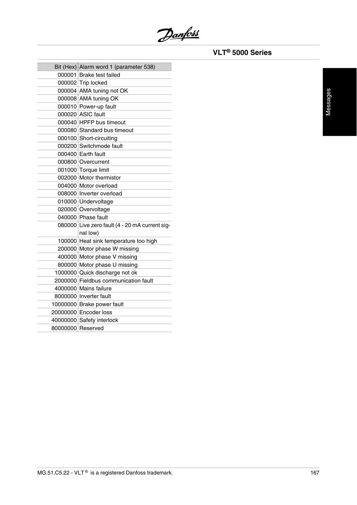
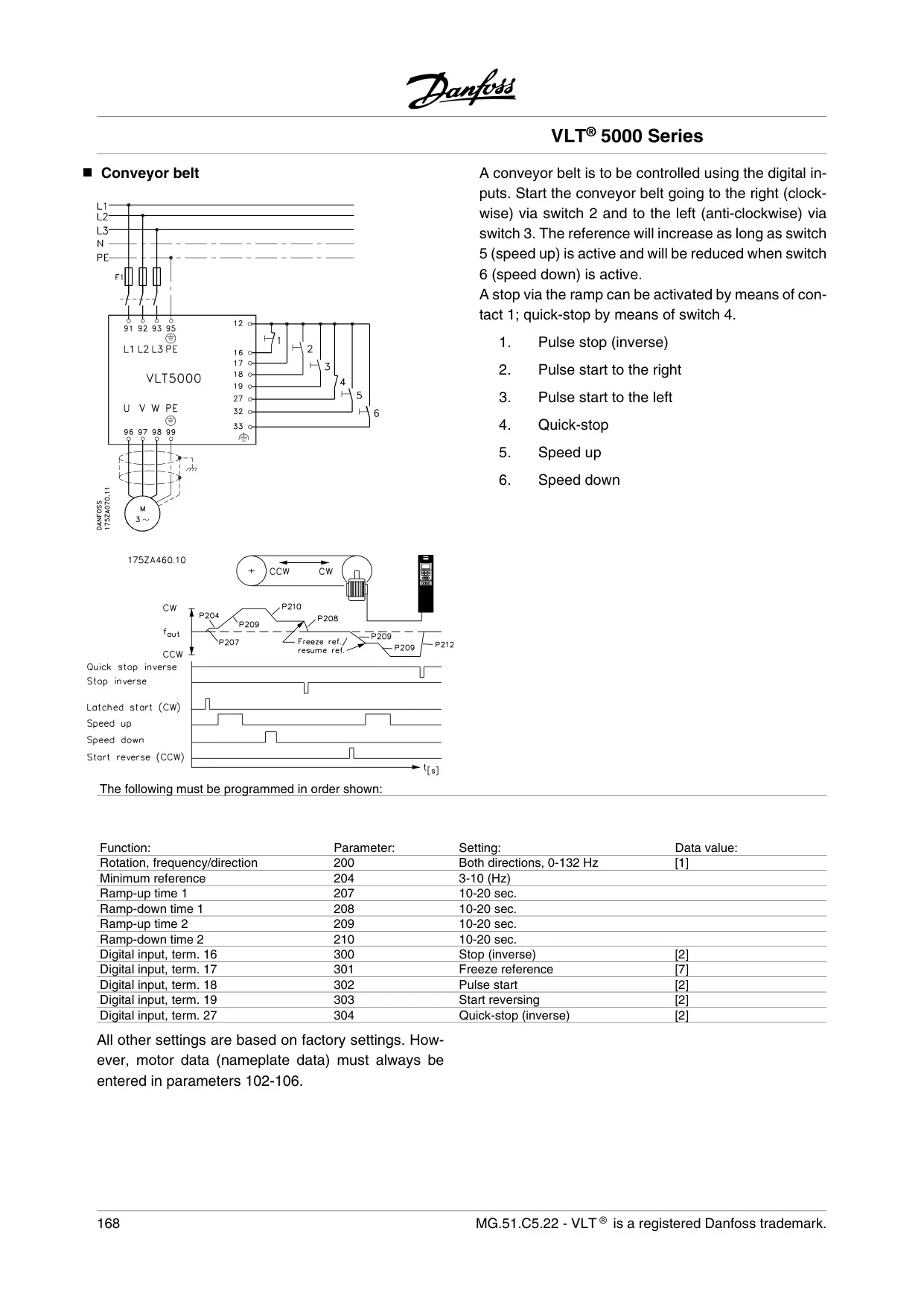
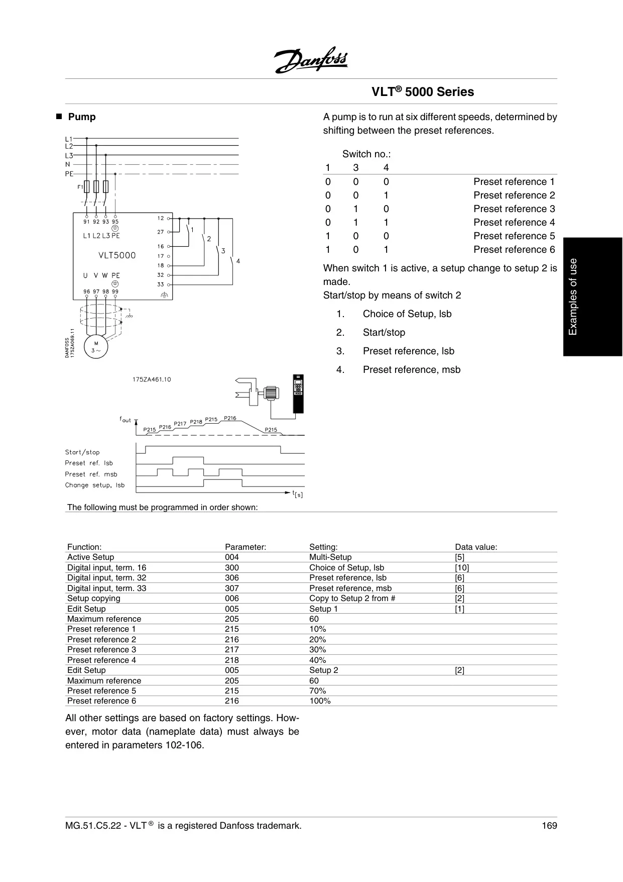
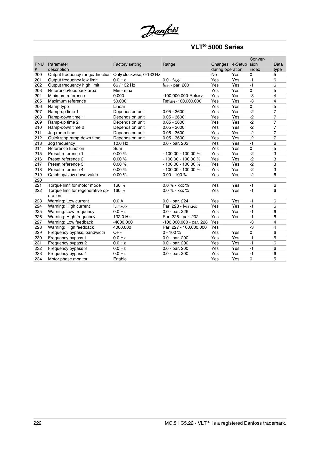
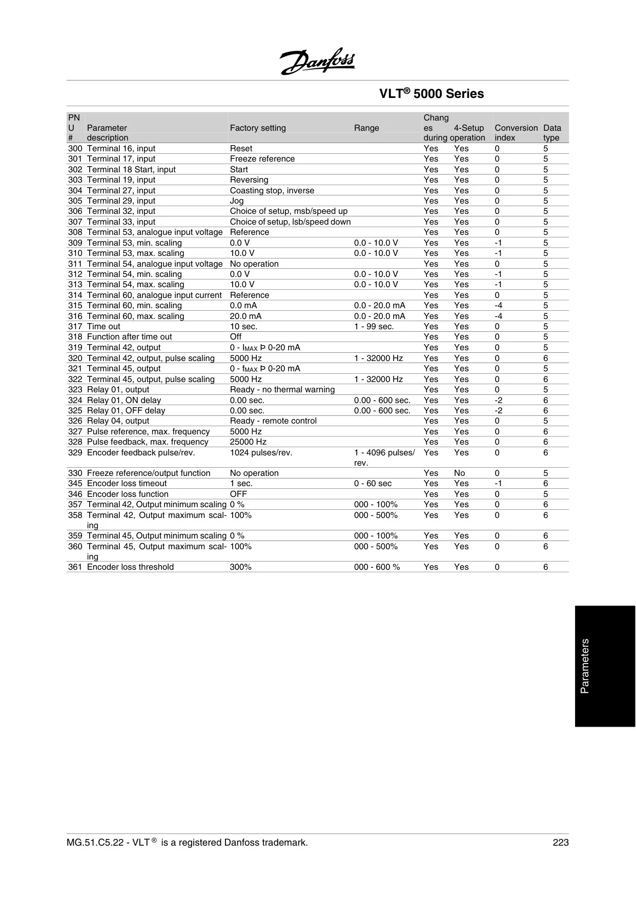
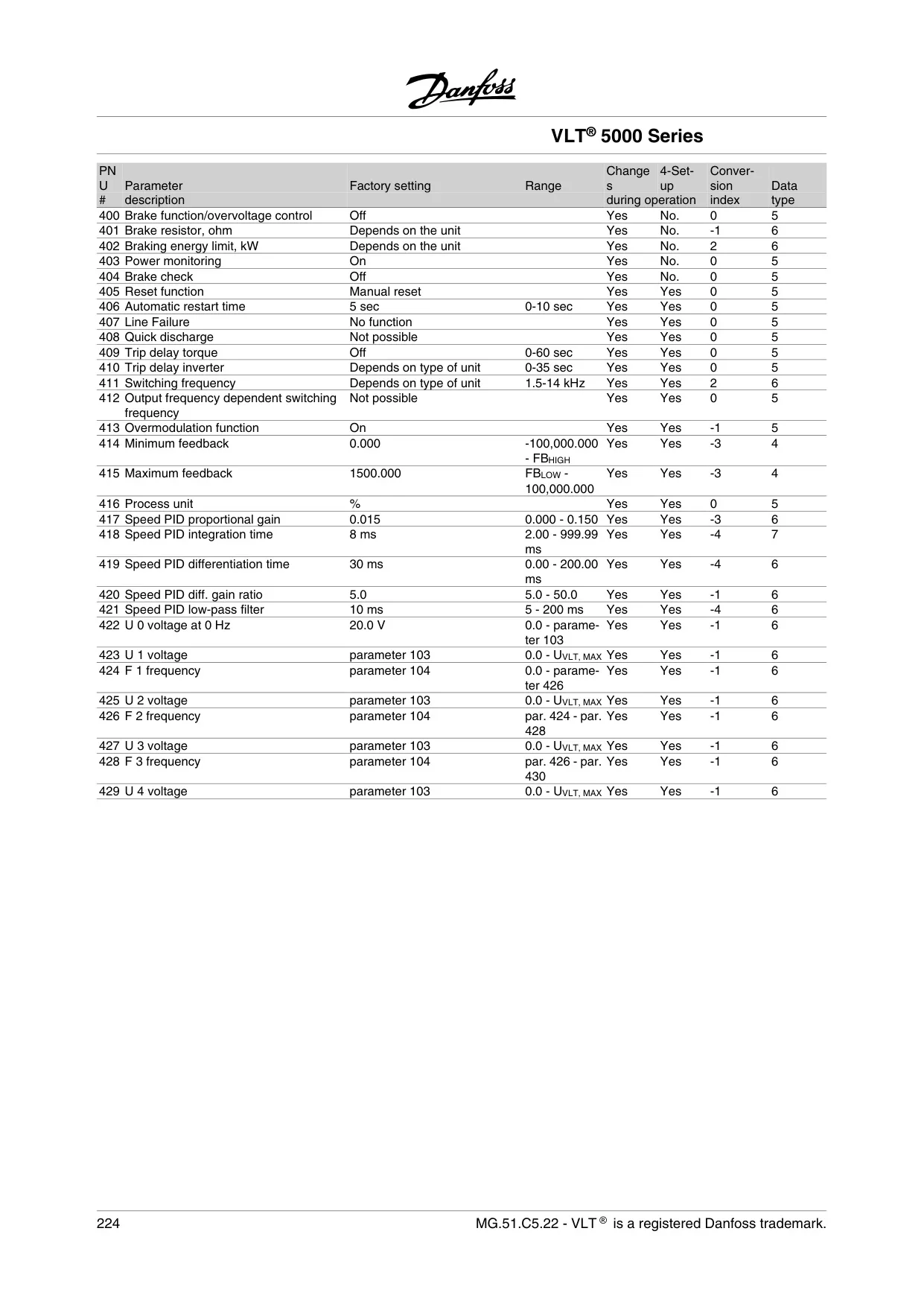
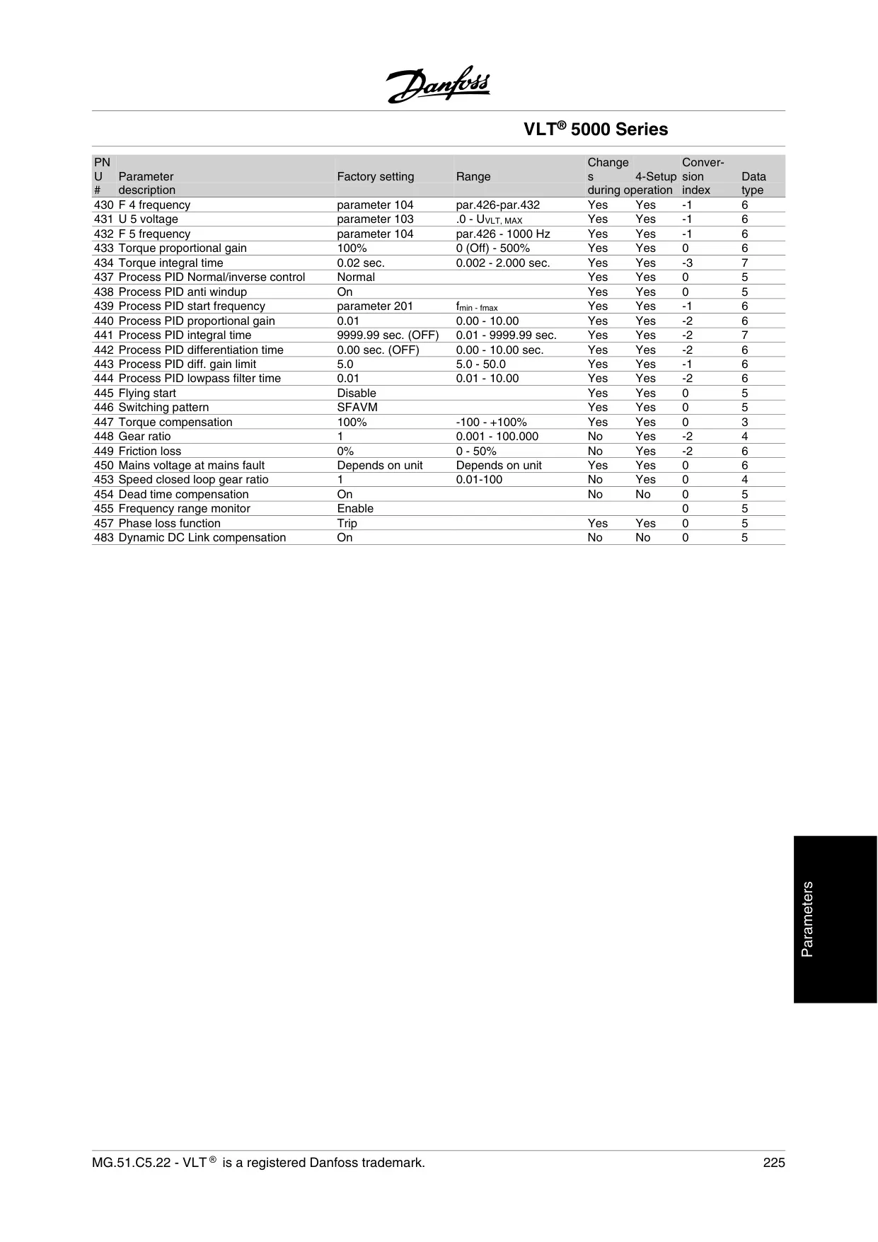


Danfoss VLT 5000 Variable Frequency Drive
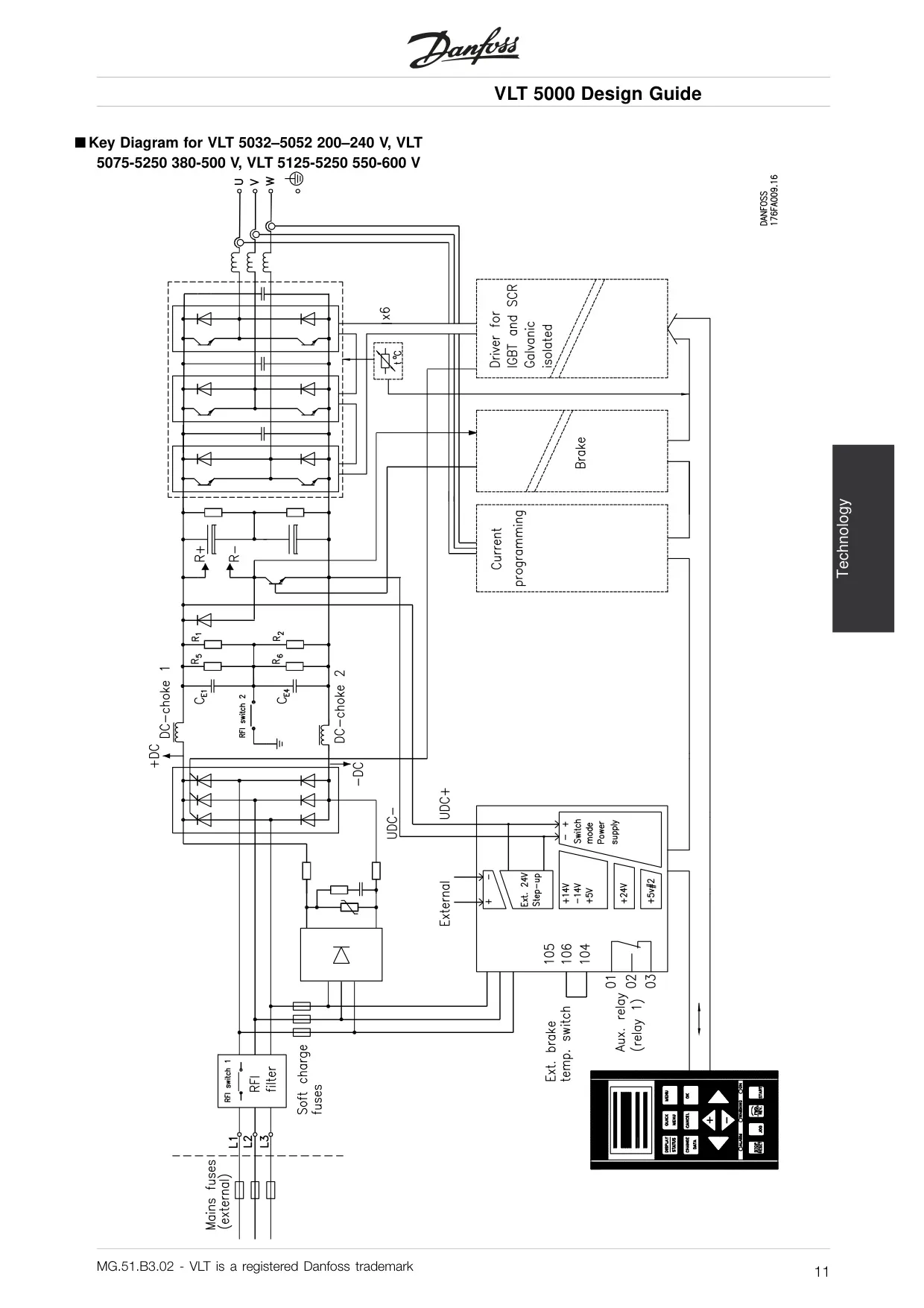
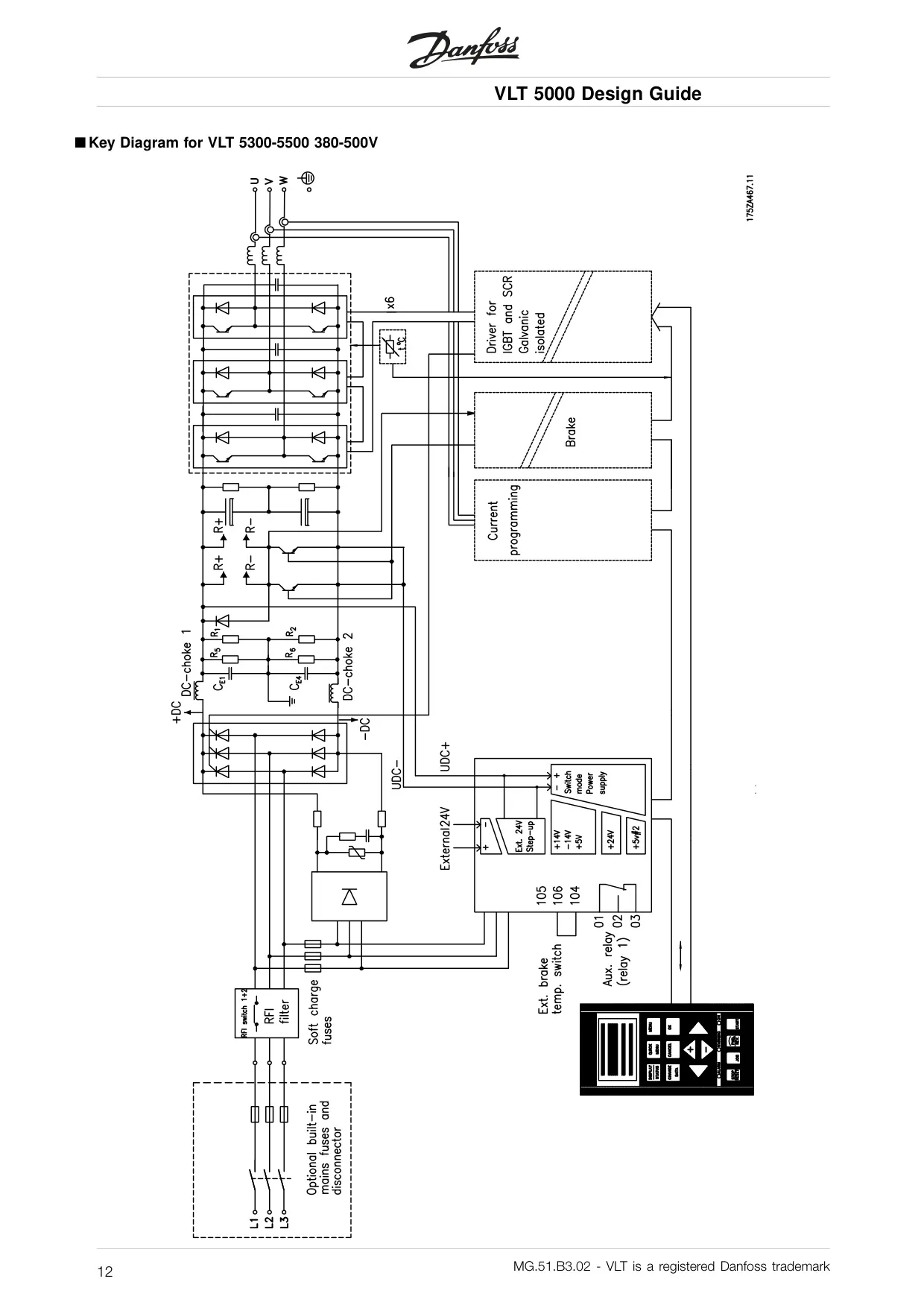
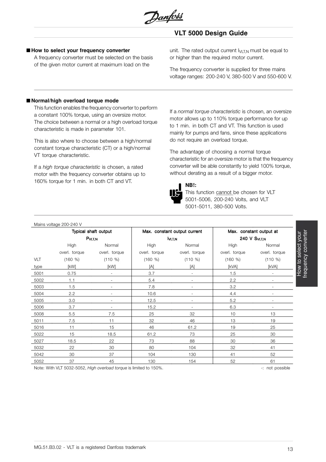
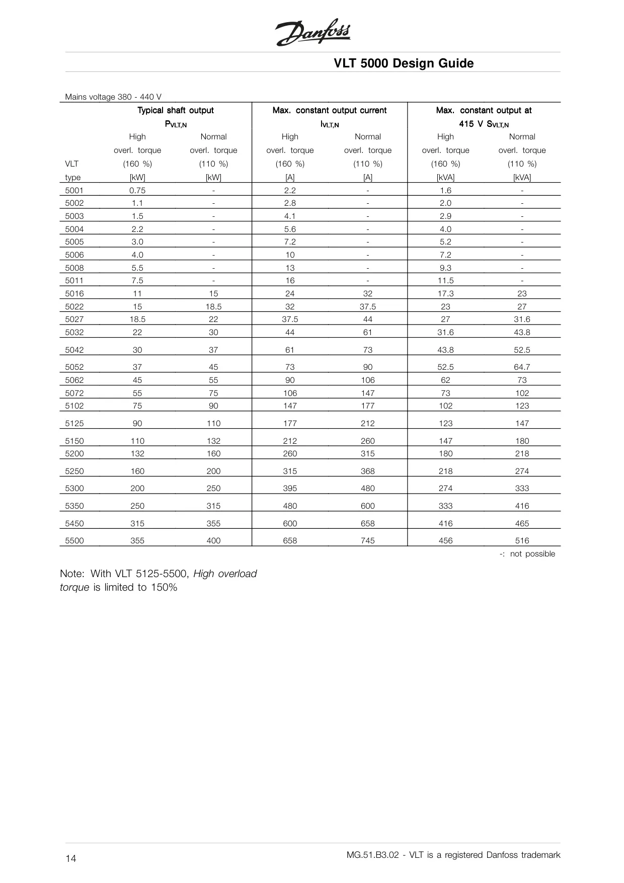

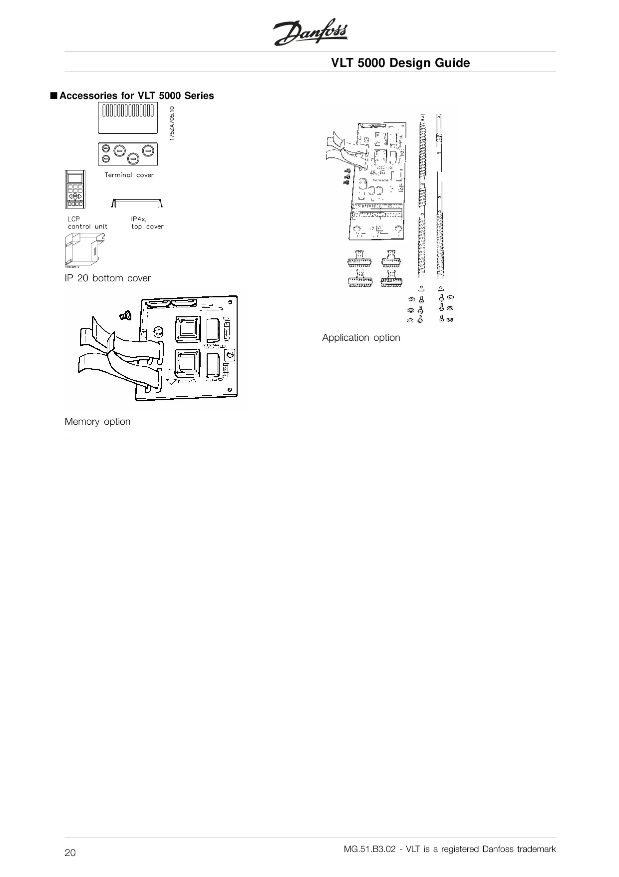
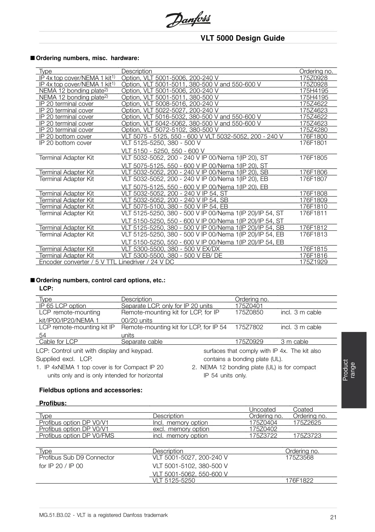
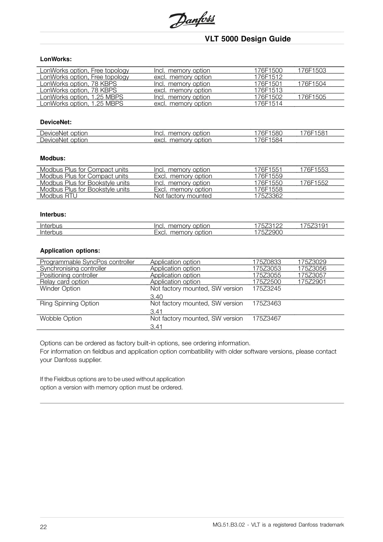
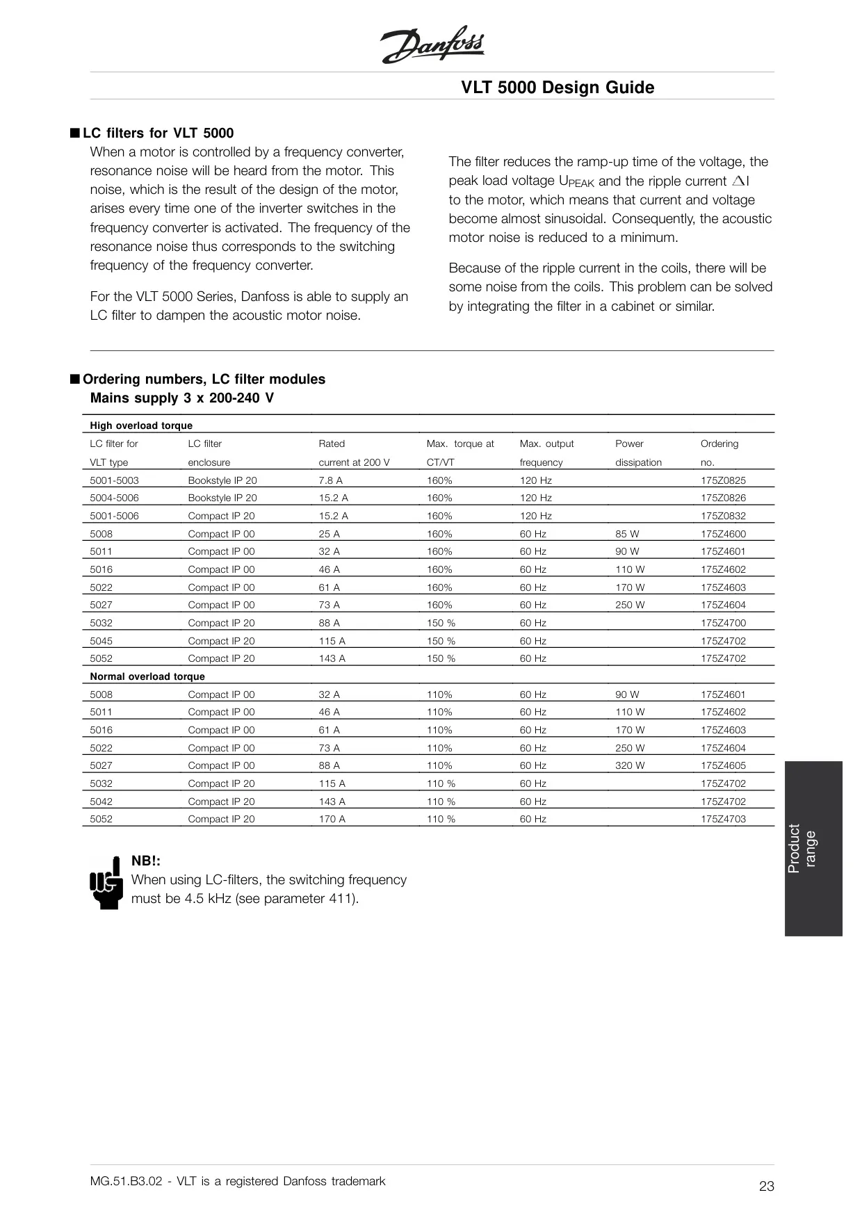
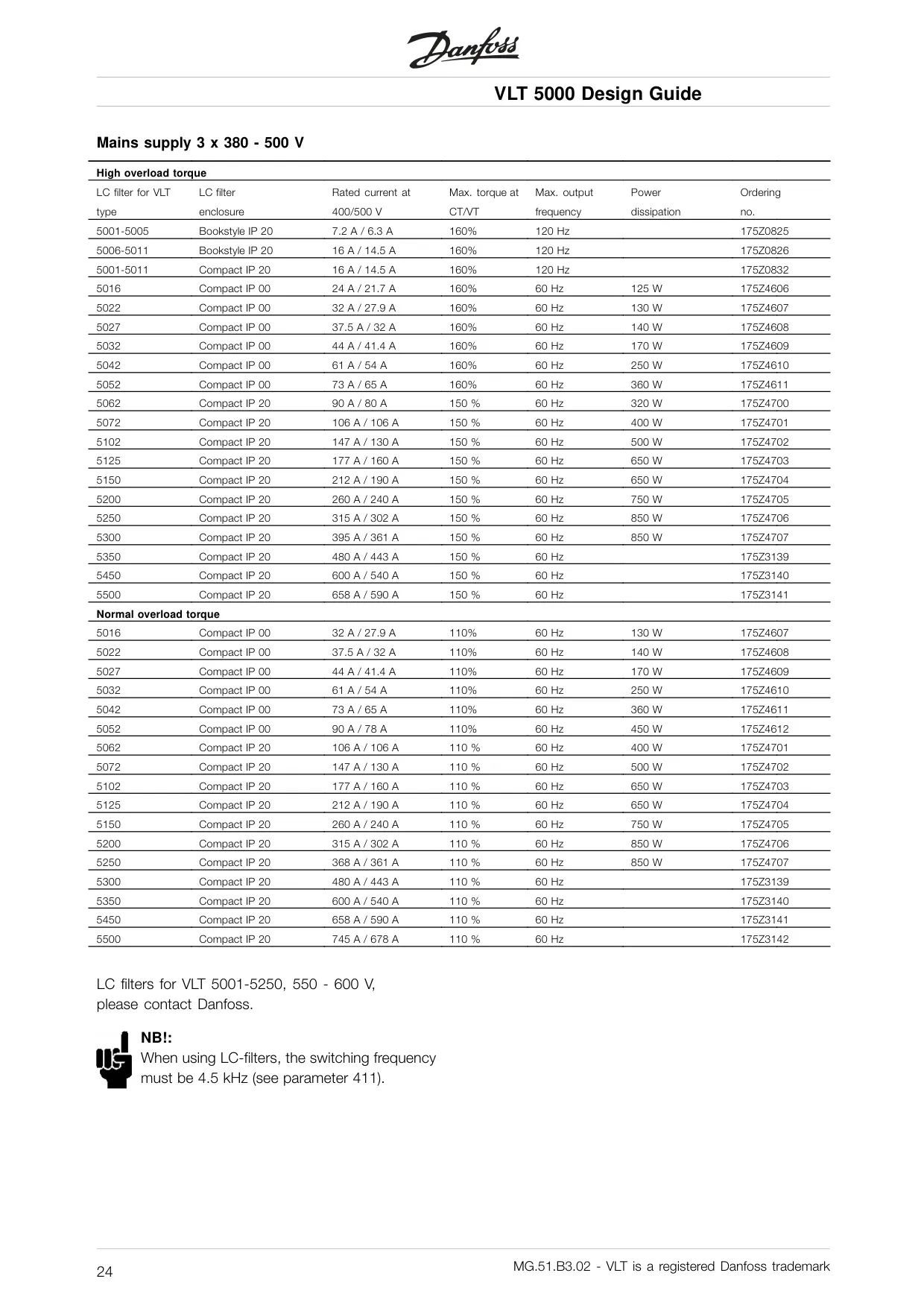
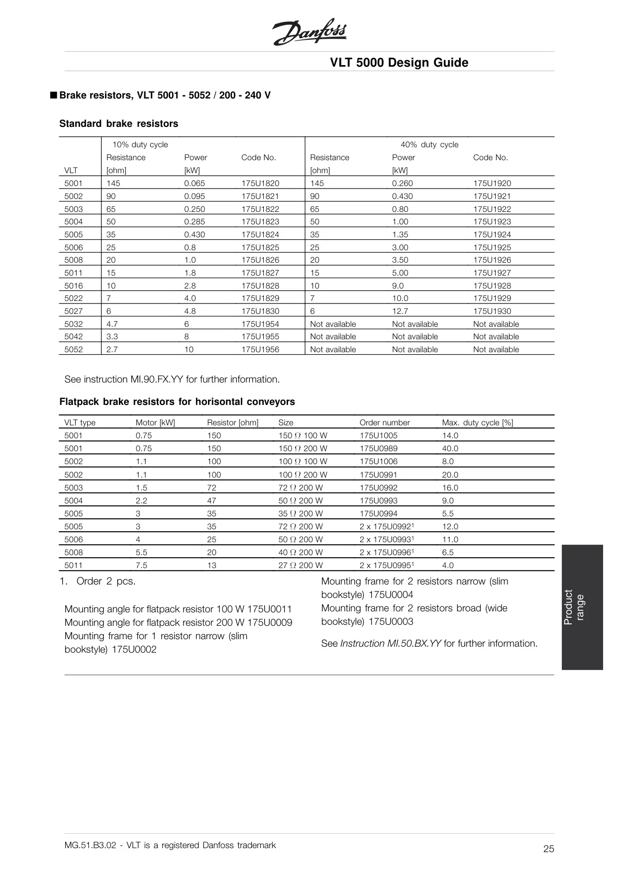
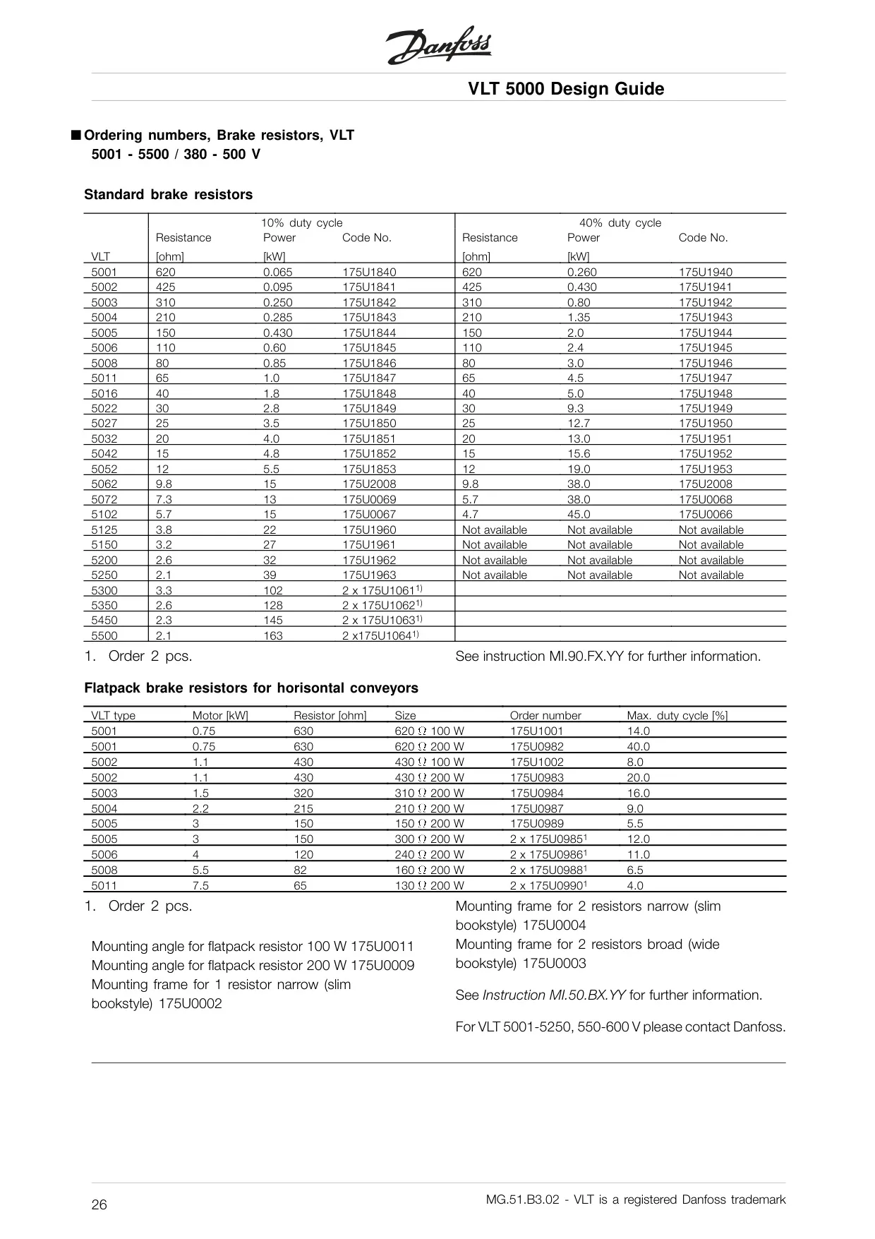
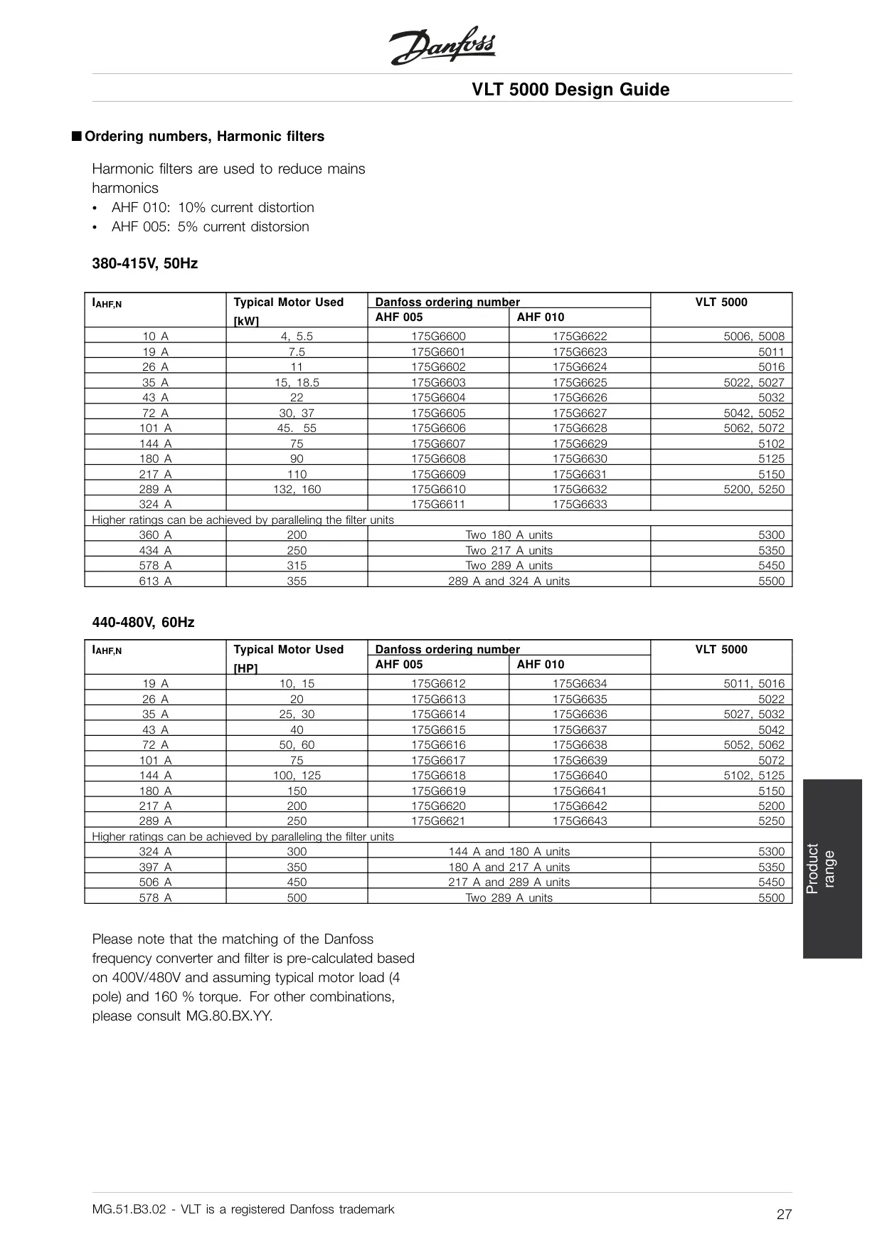

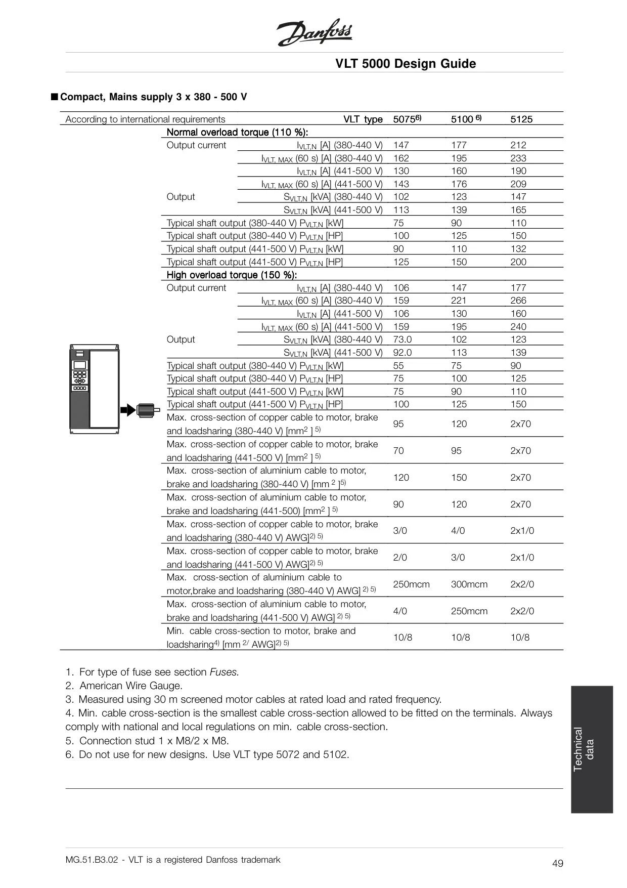
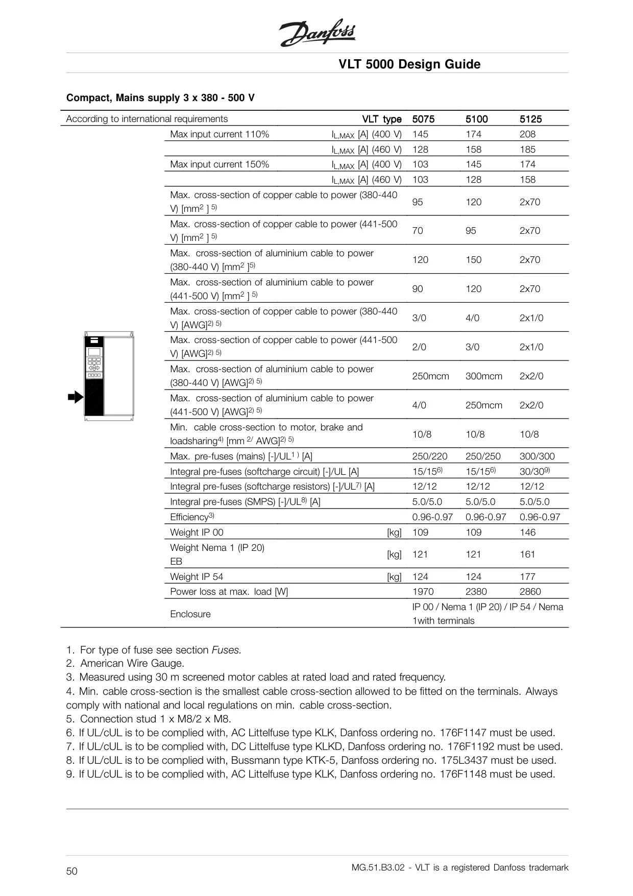
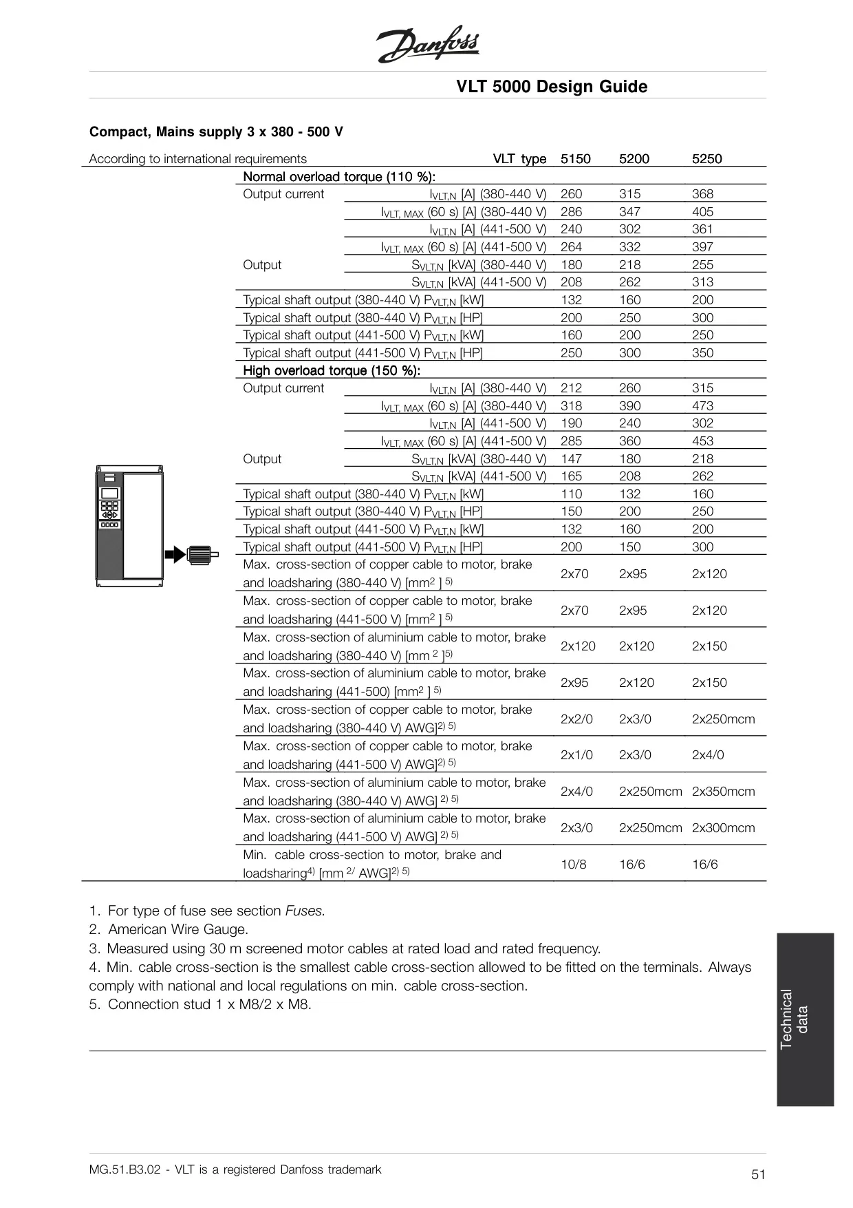
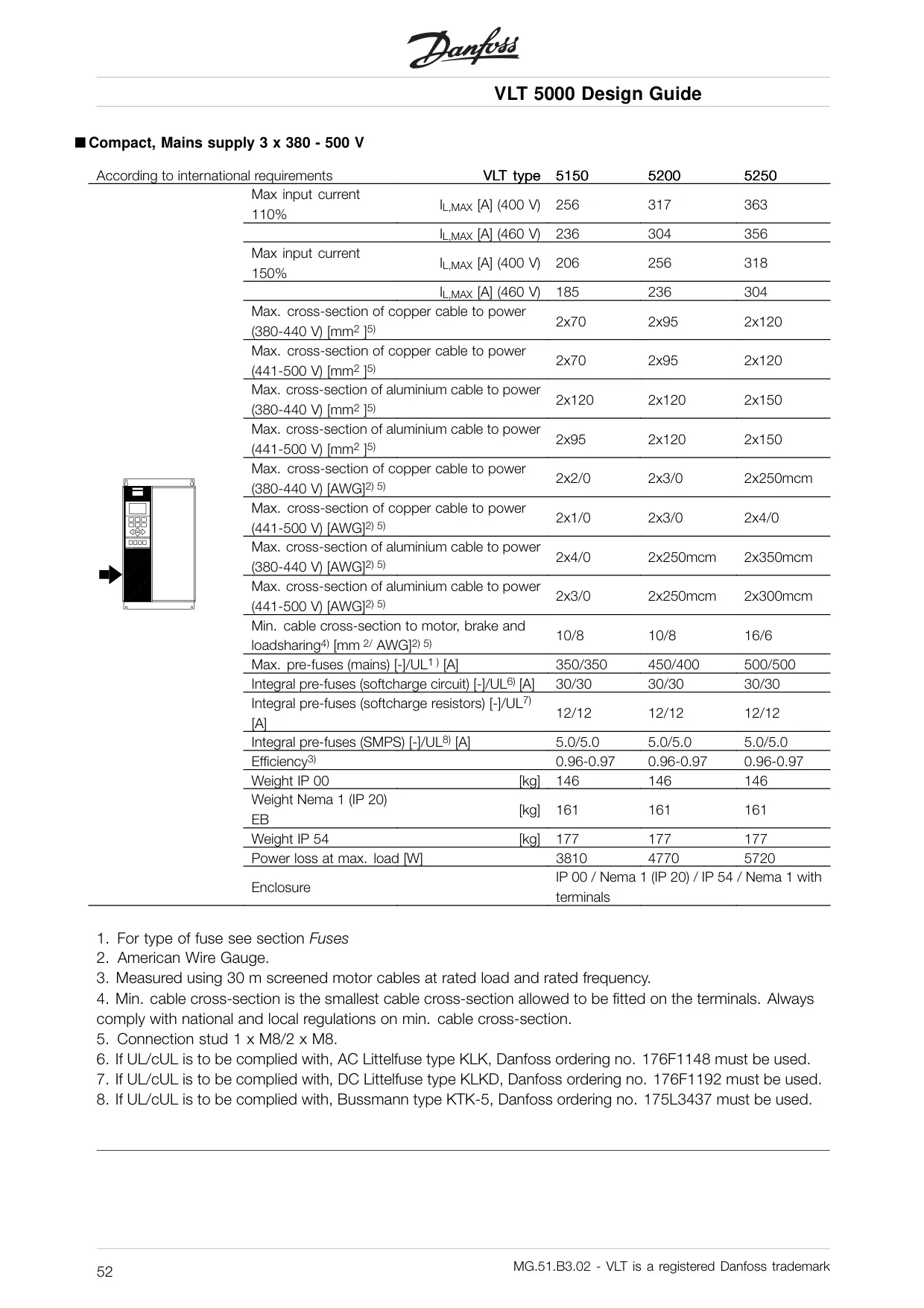
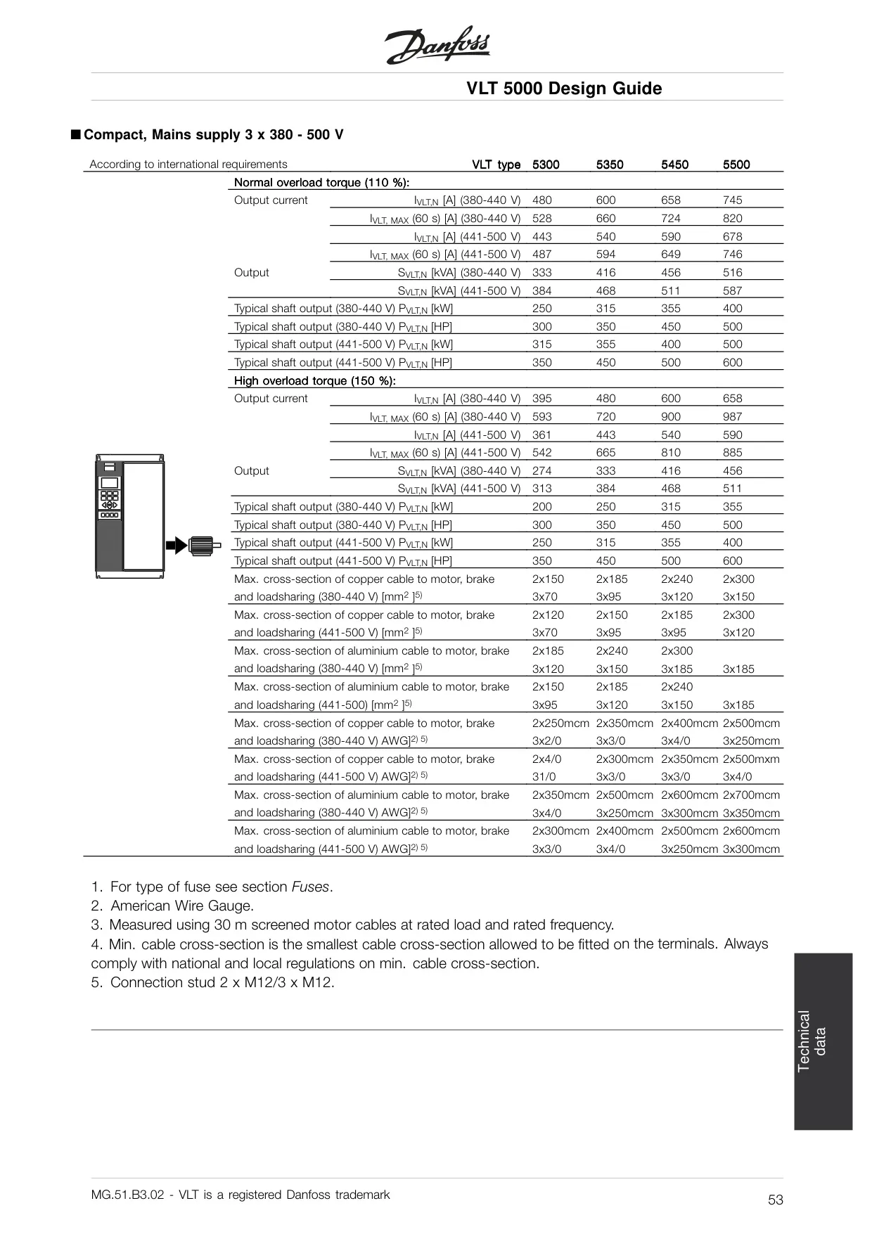
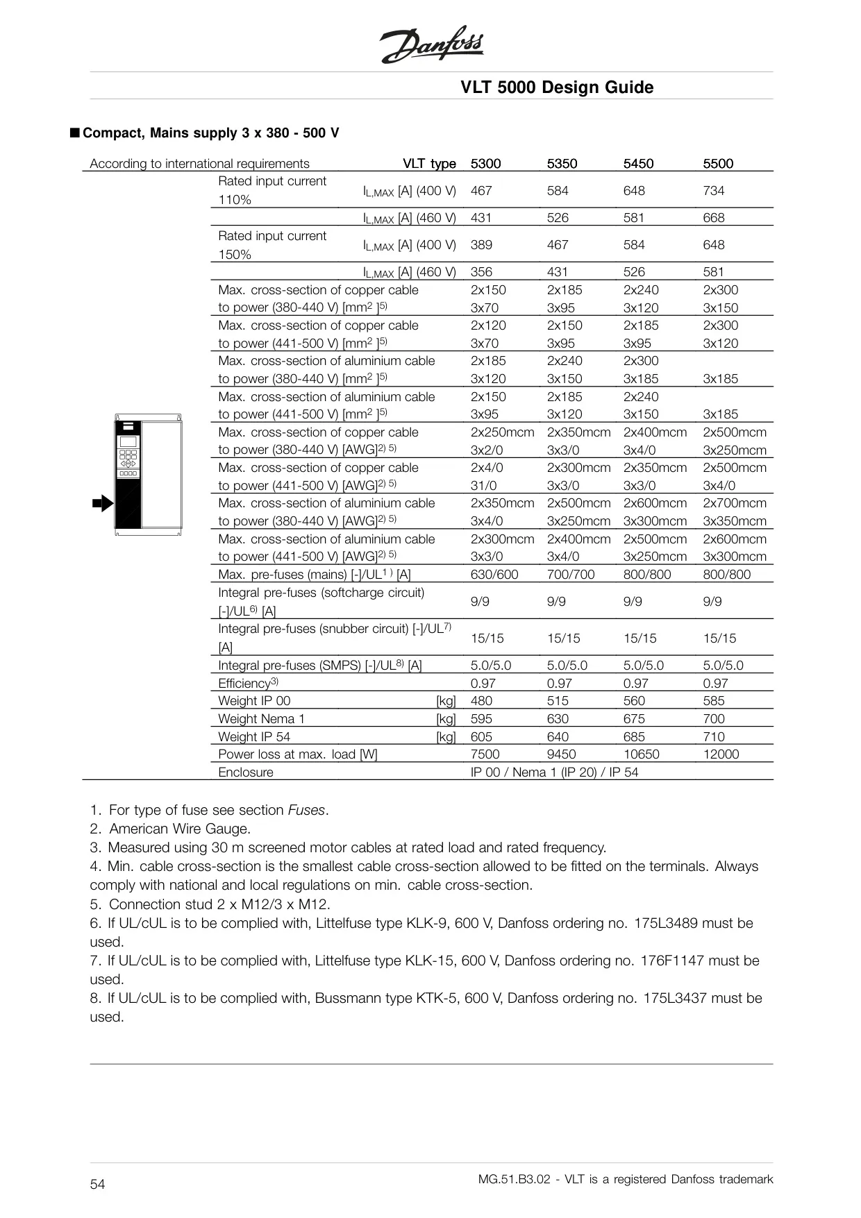
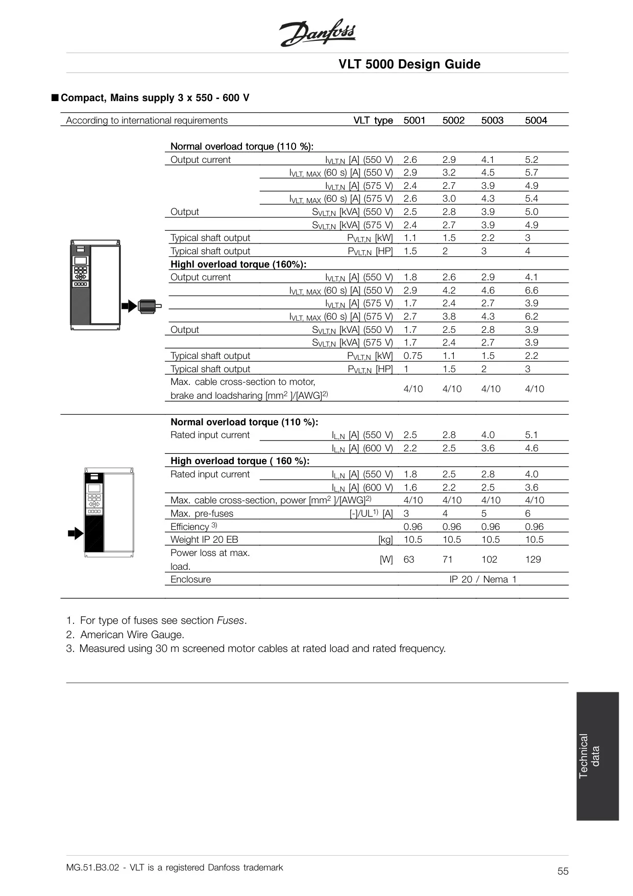
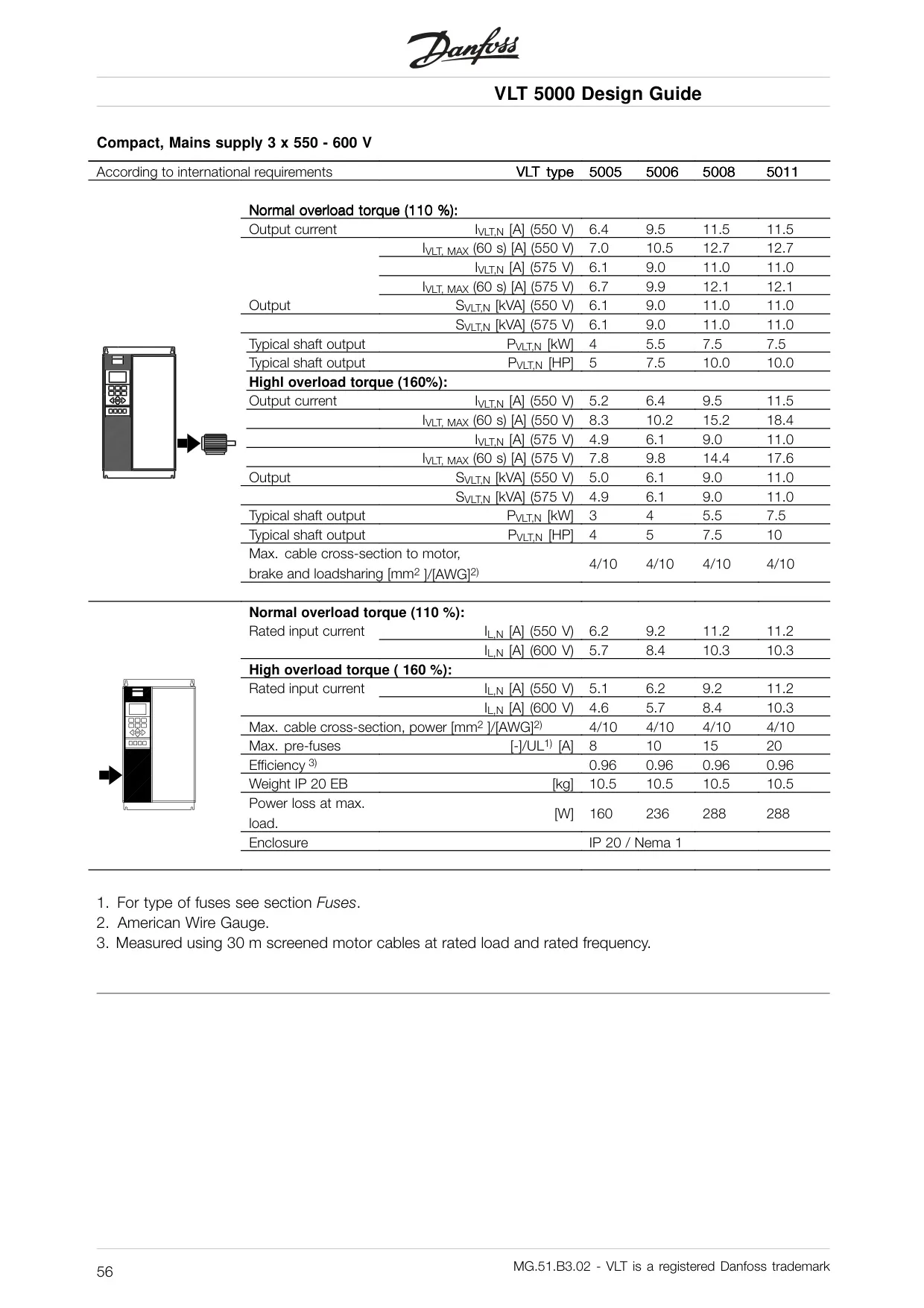
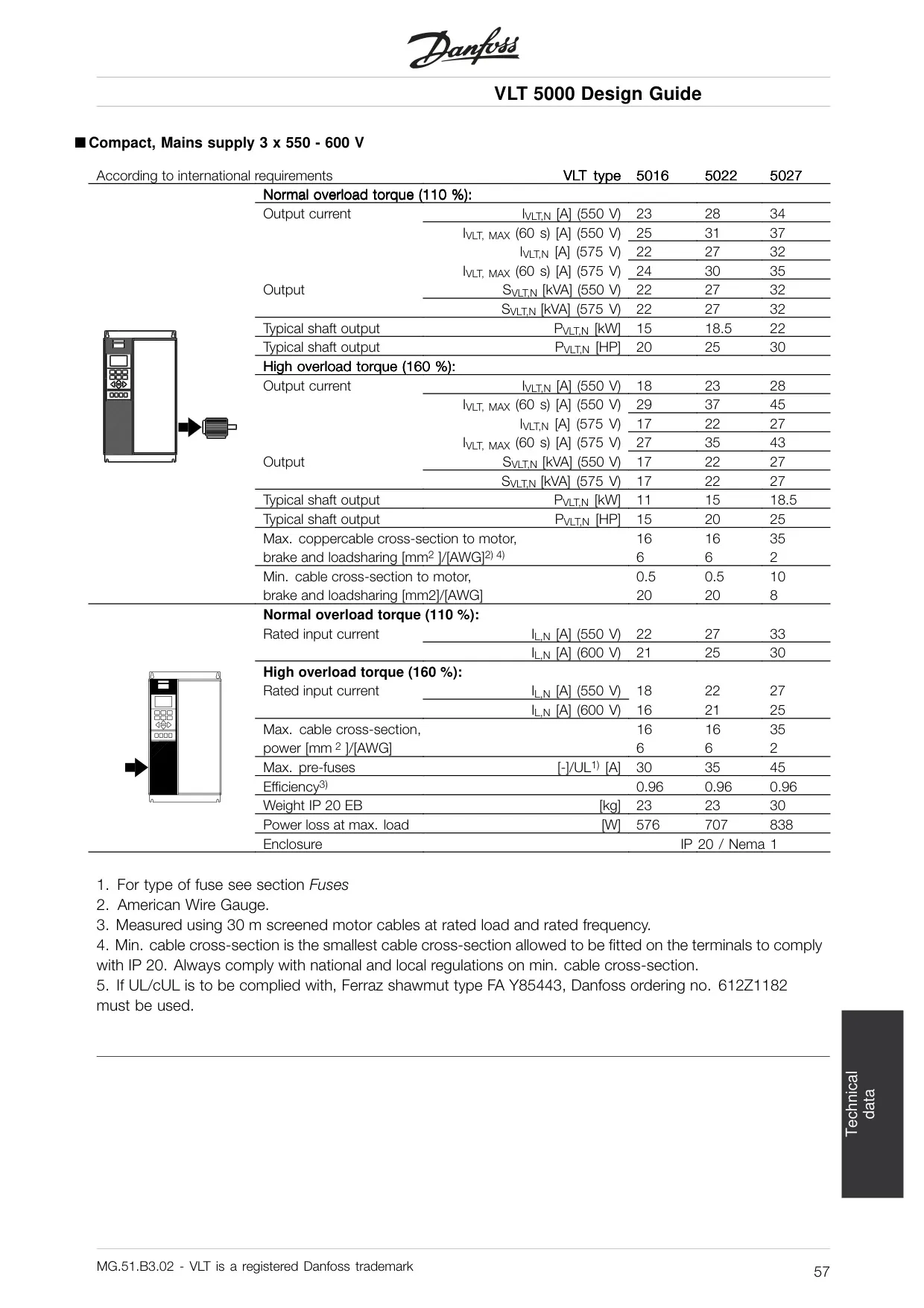
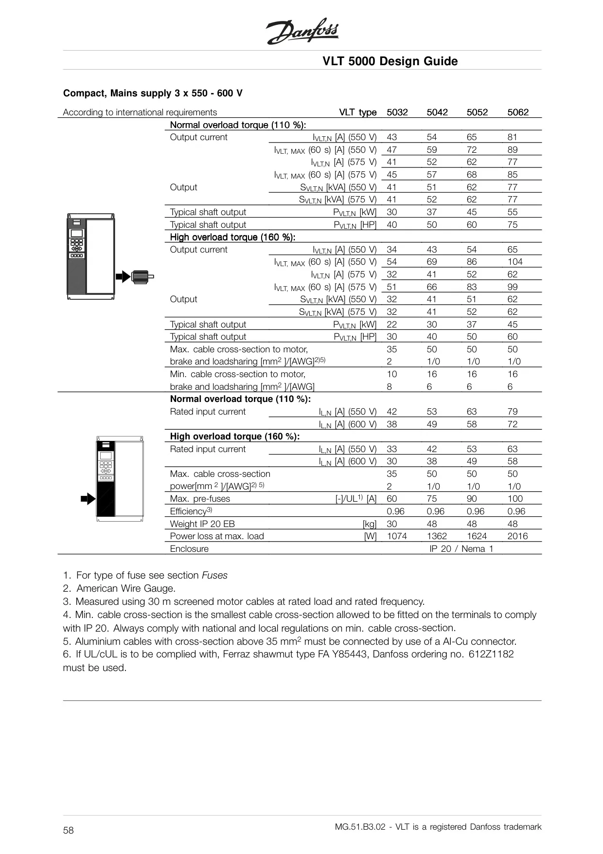
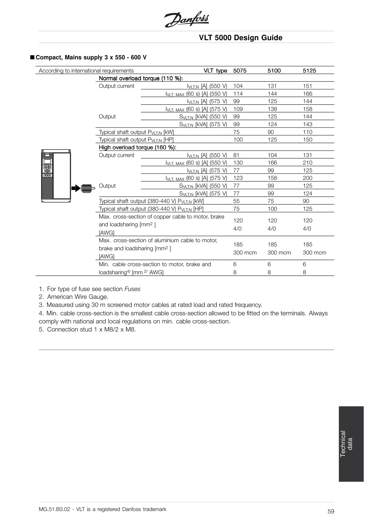
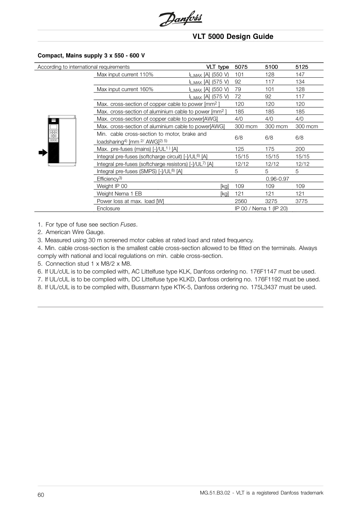
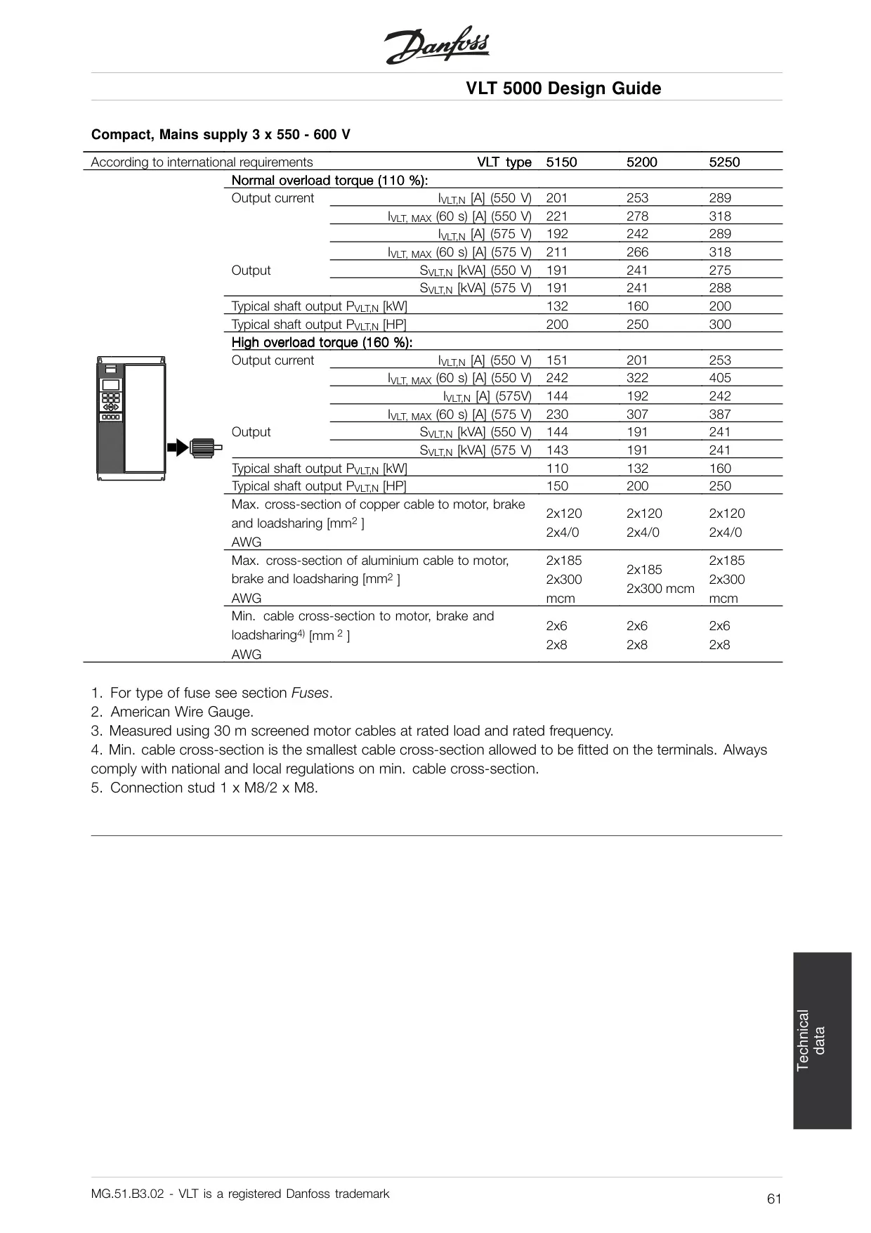
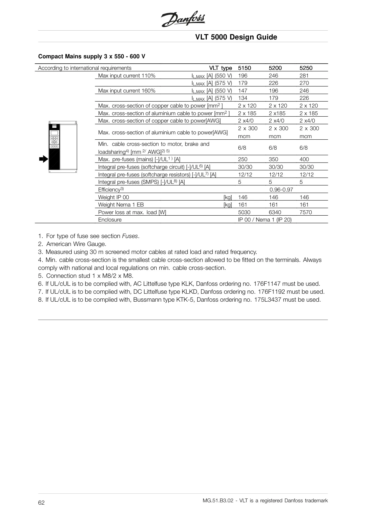
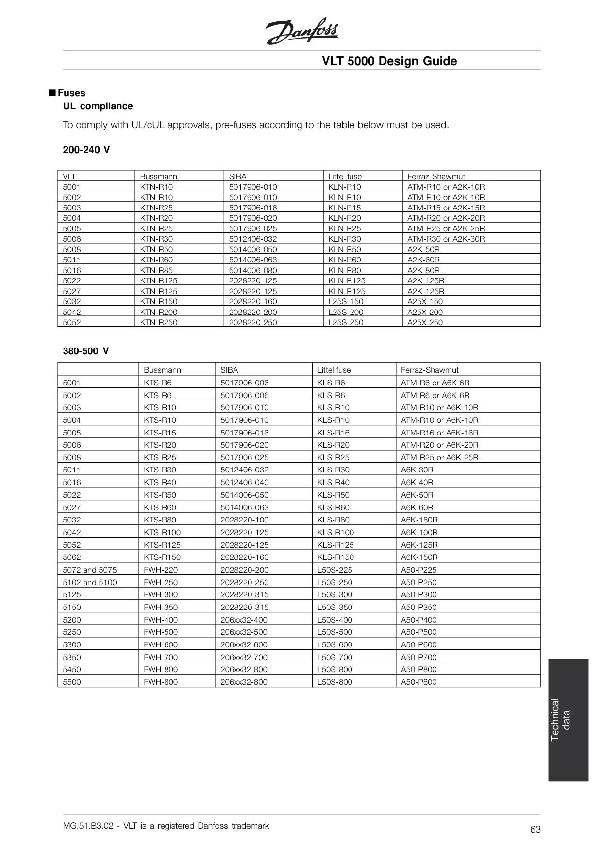
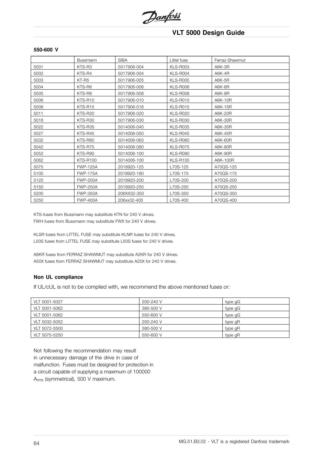
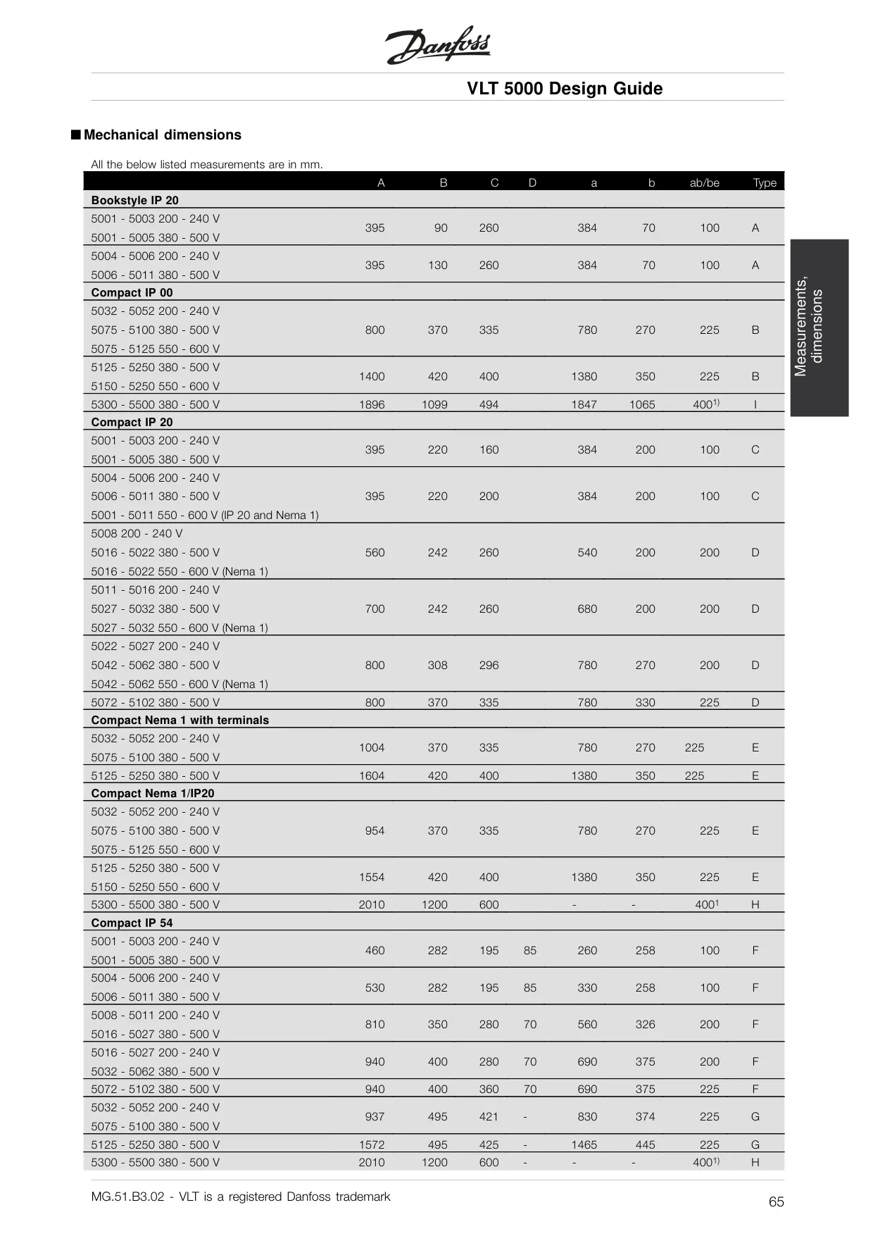
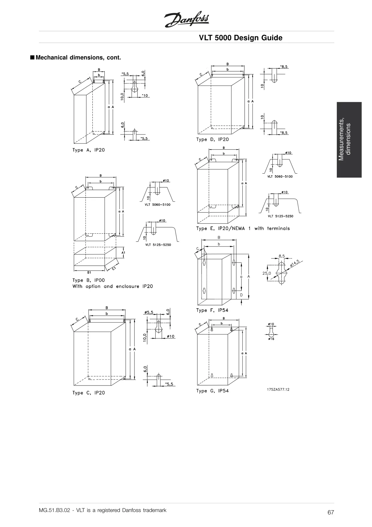
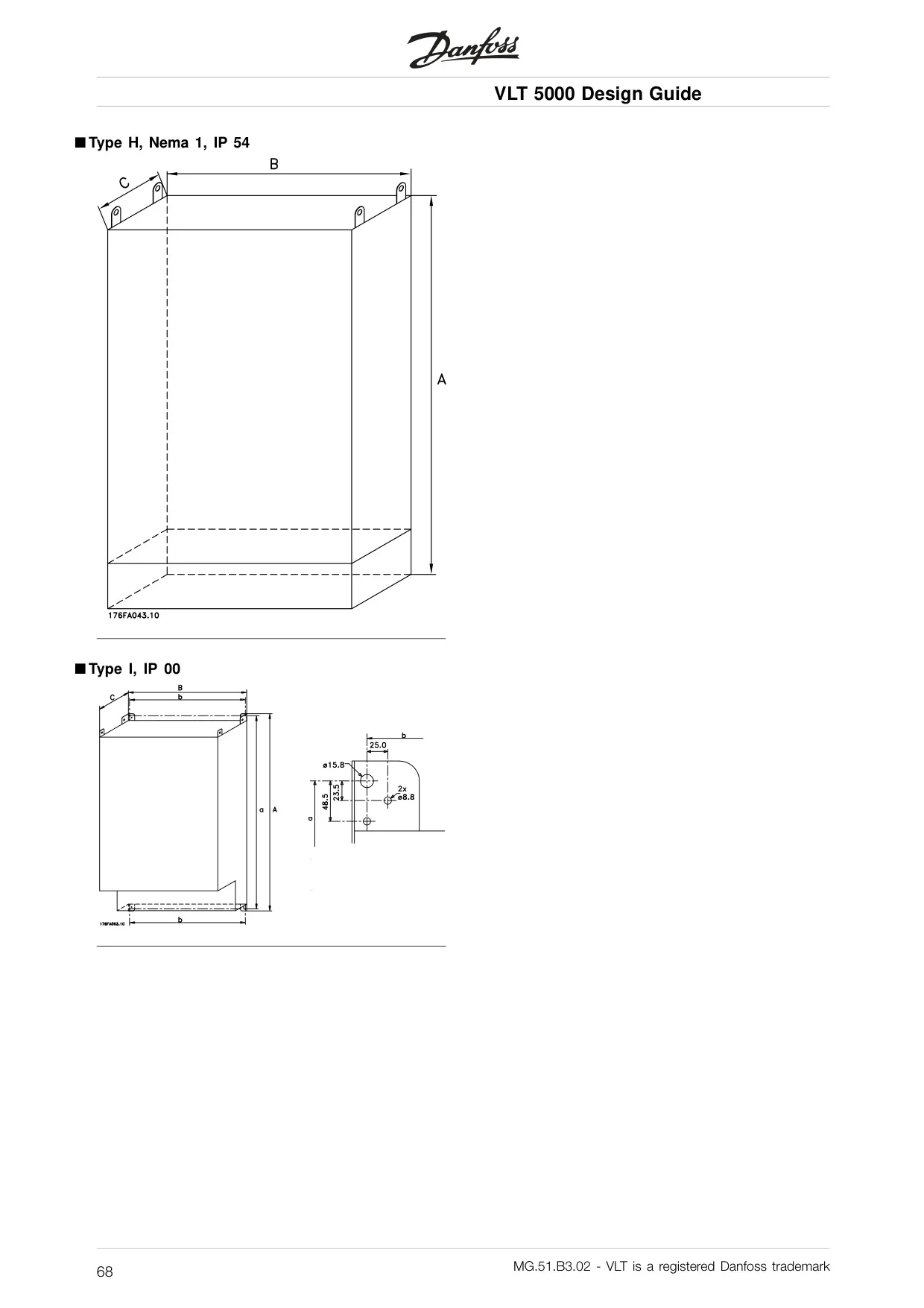
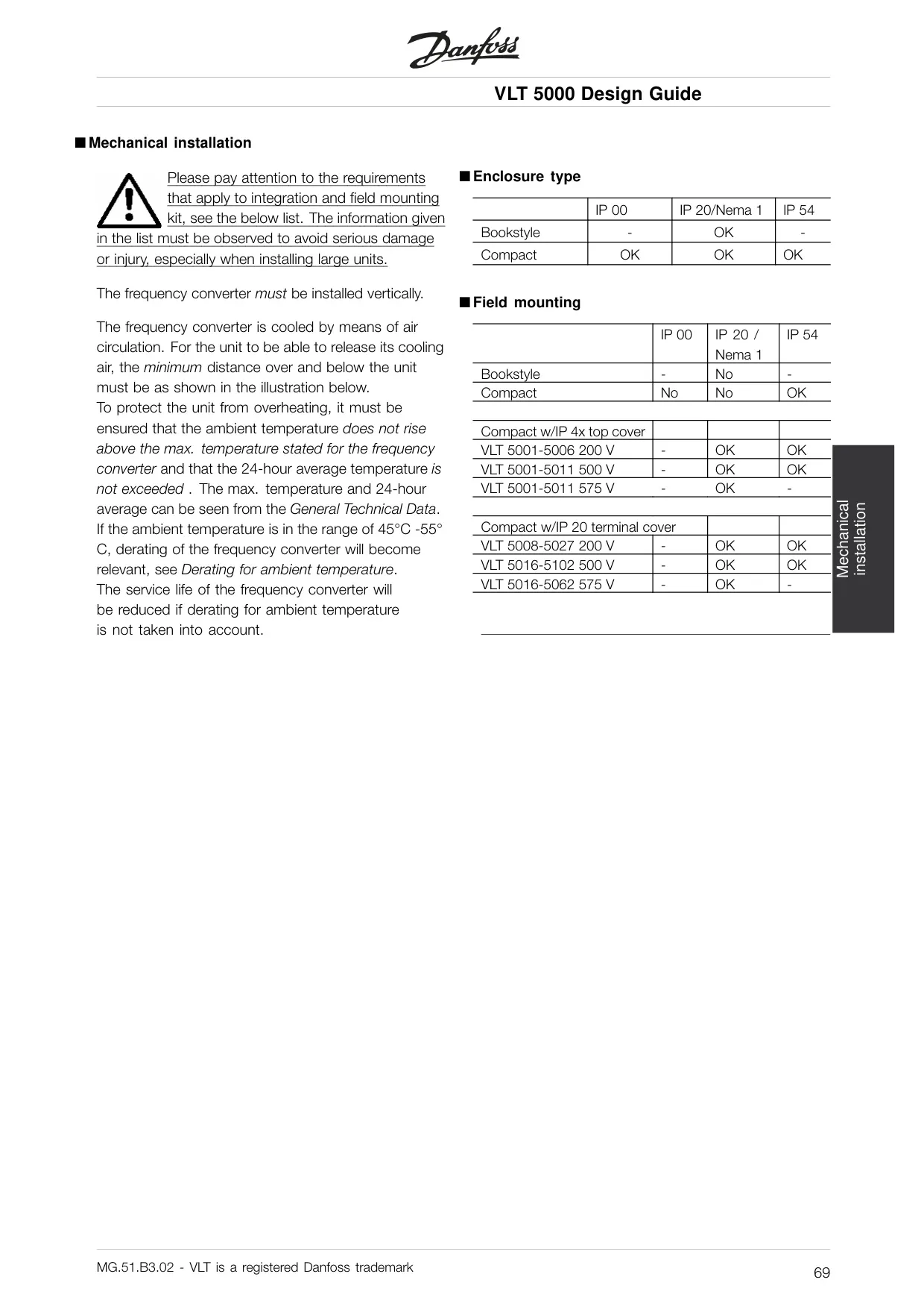
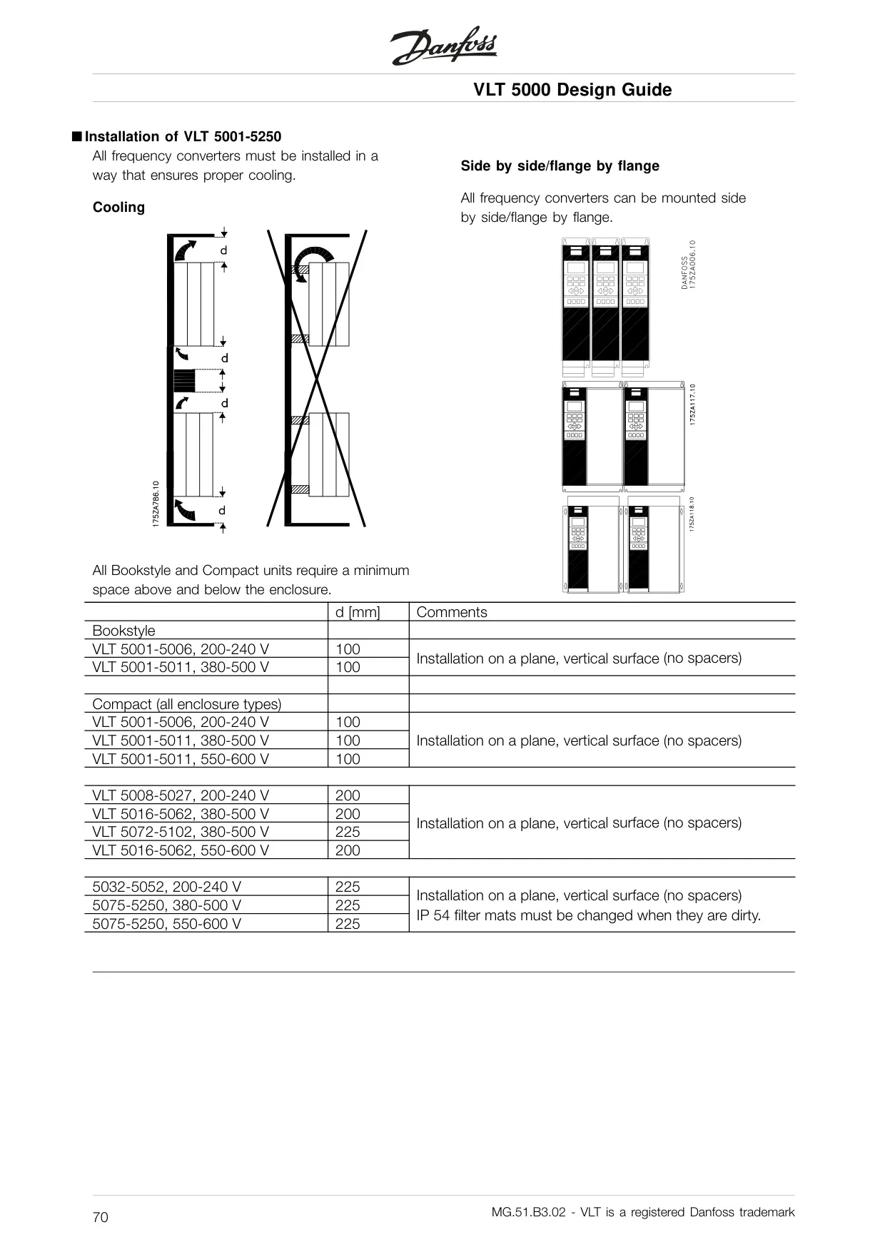
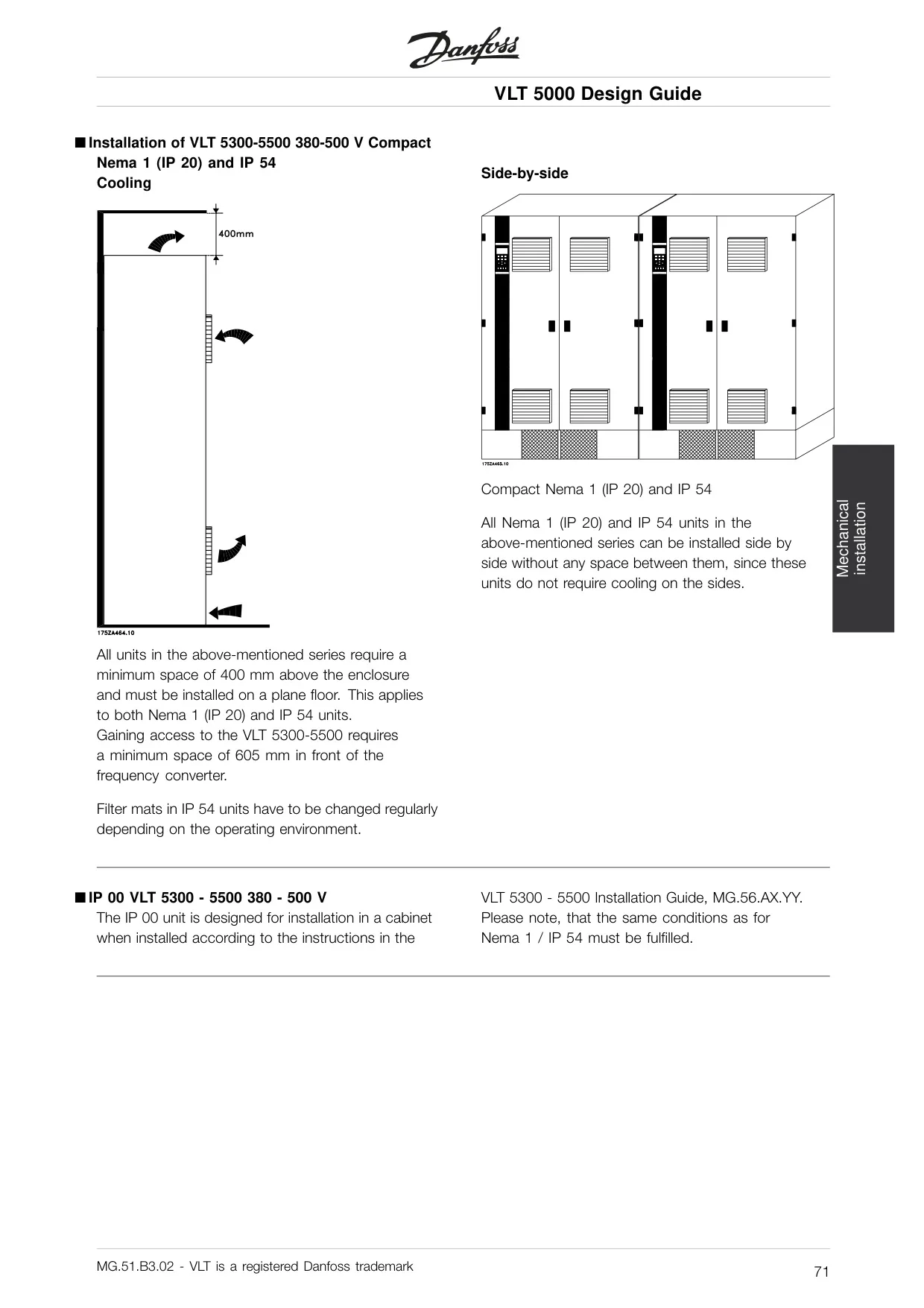
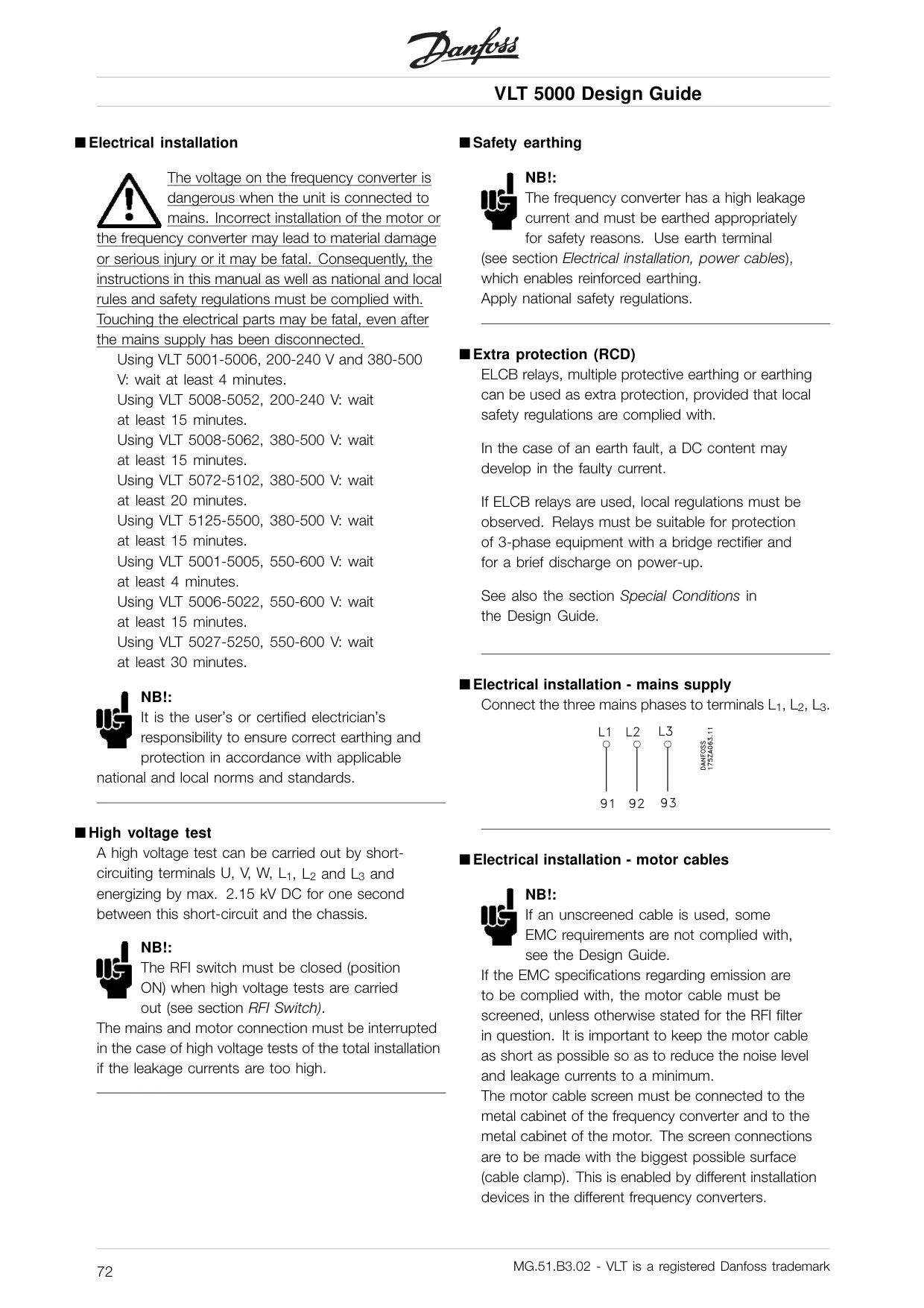
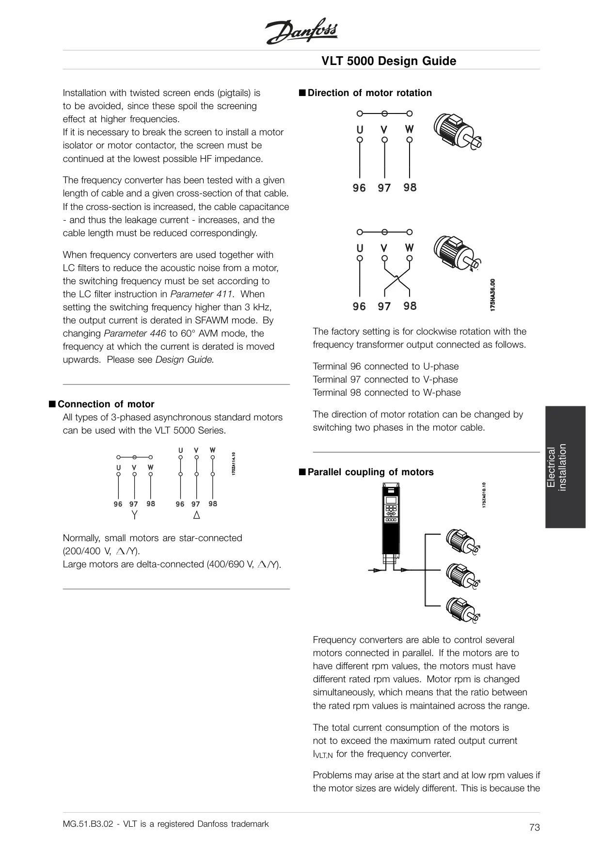
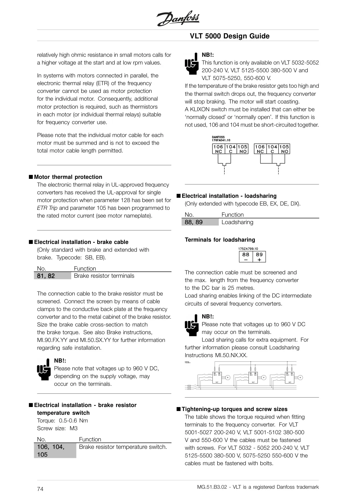
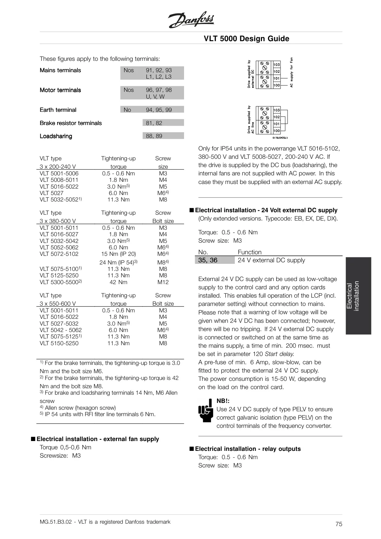
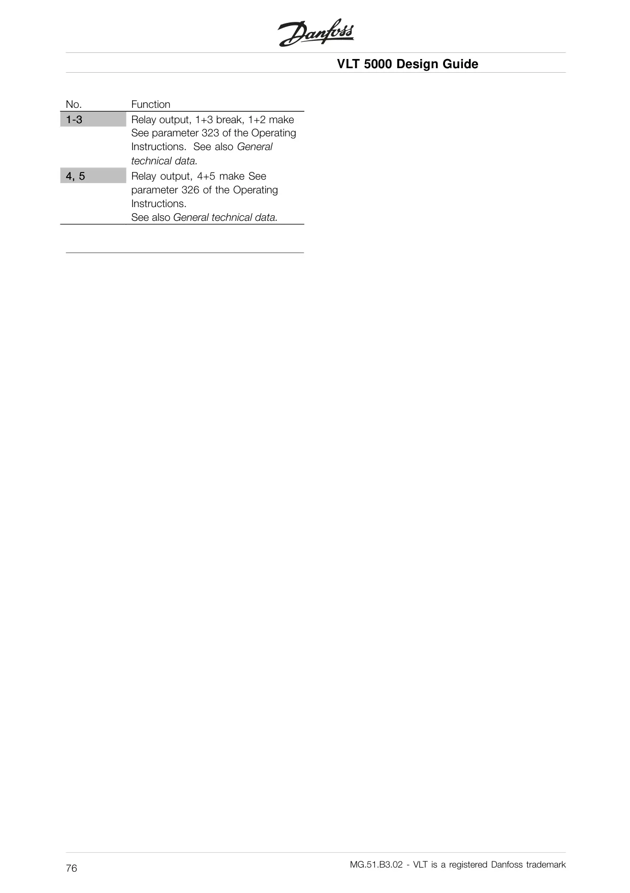
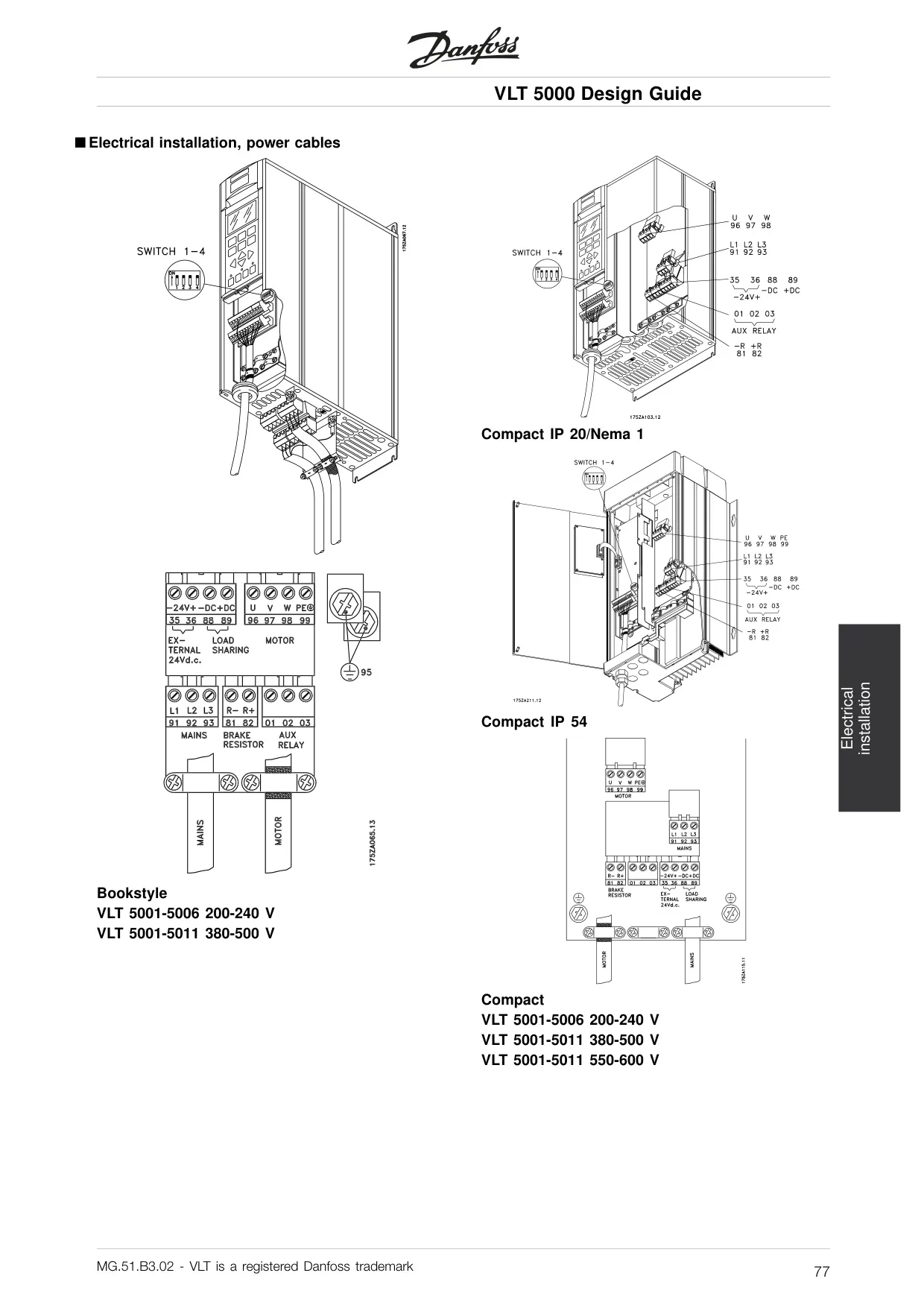
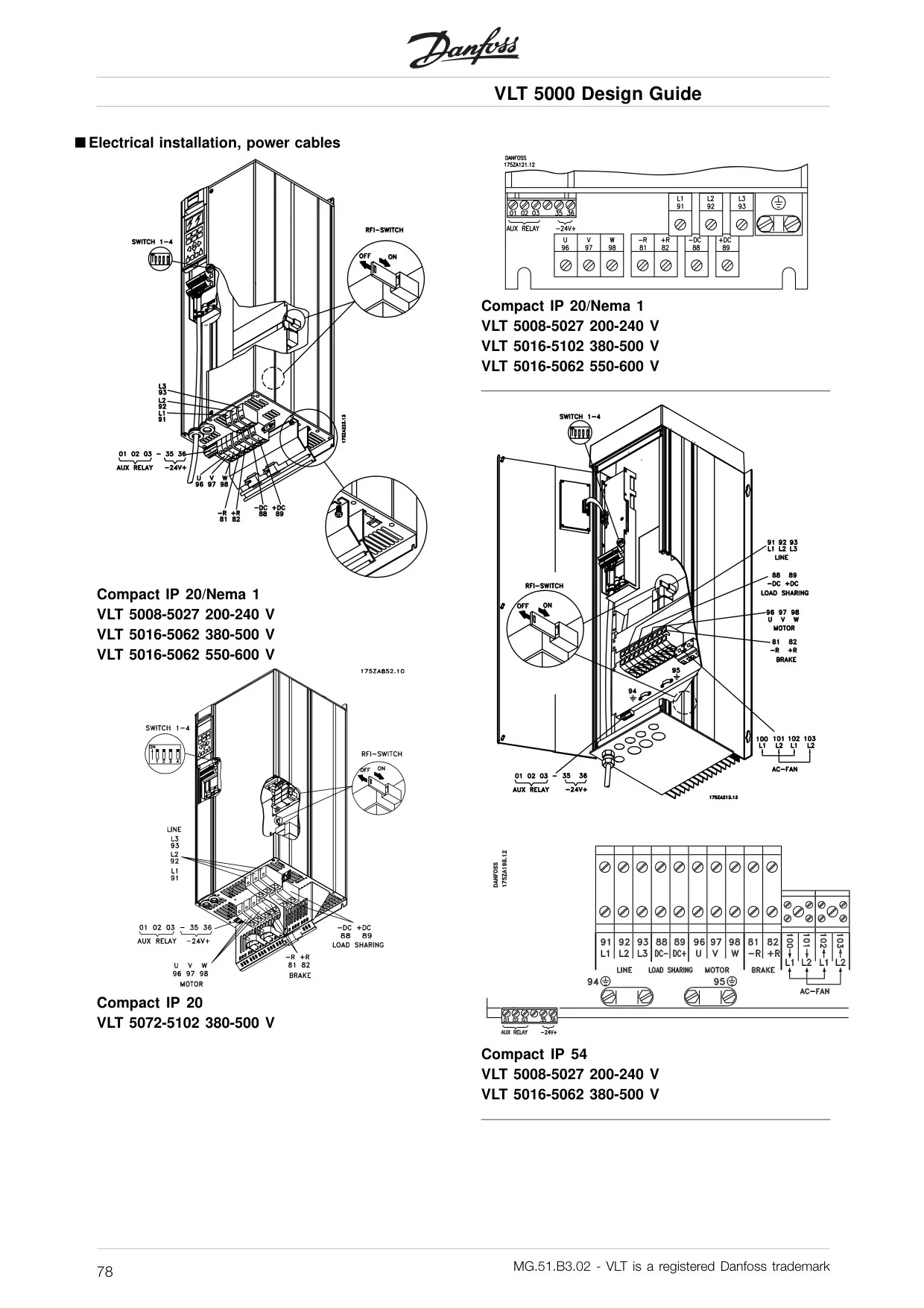
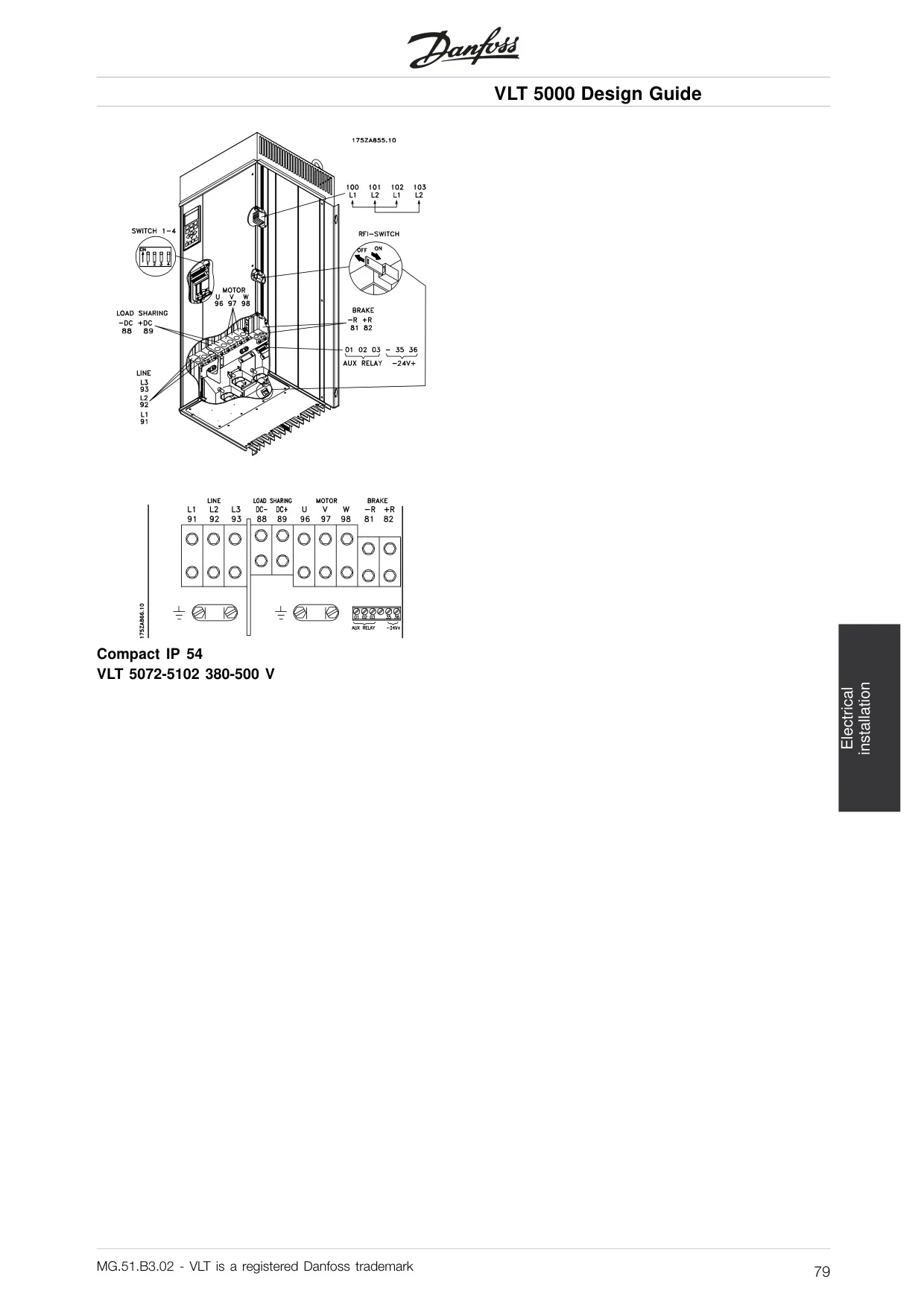
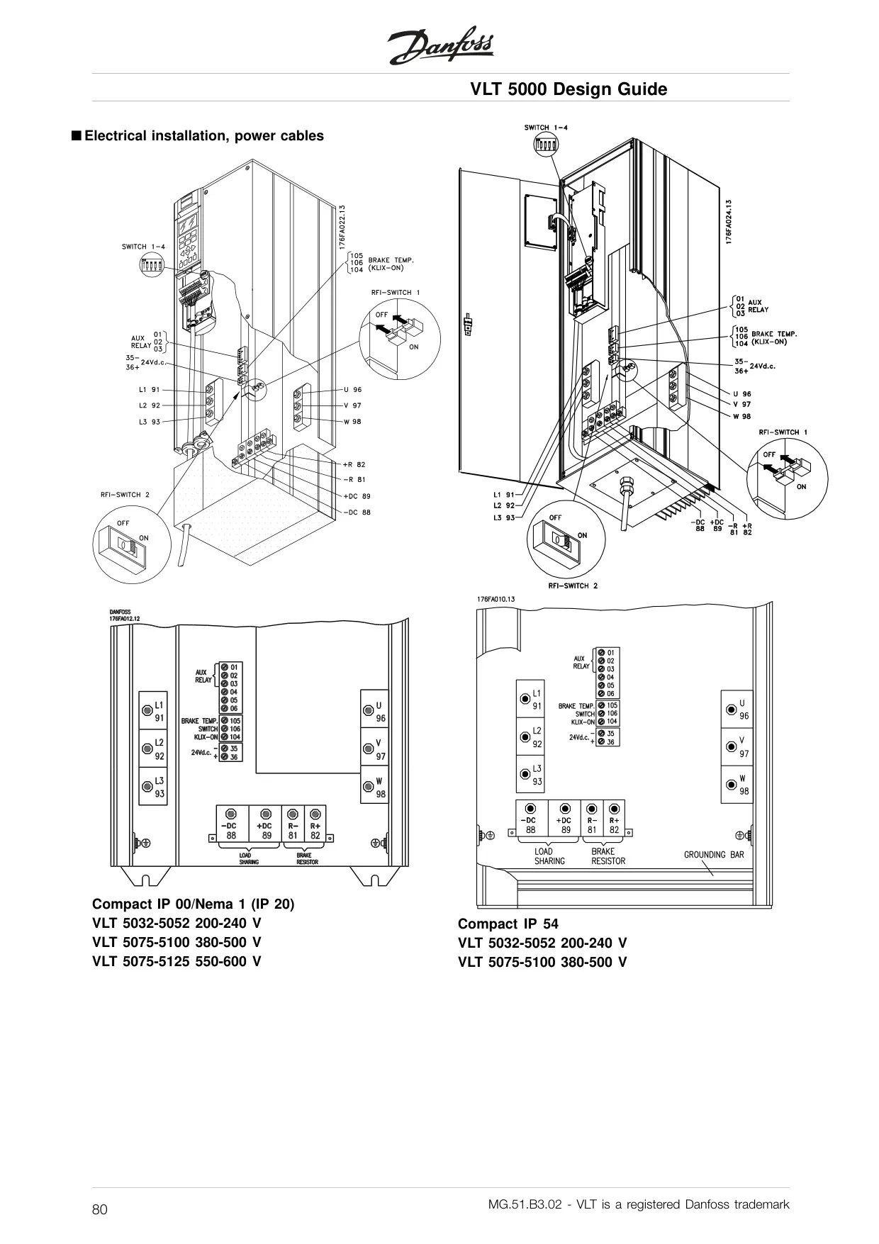
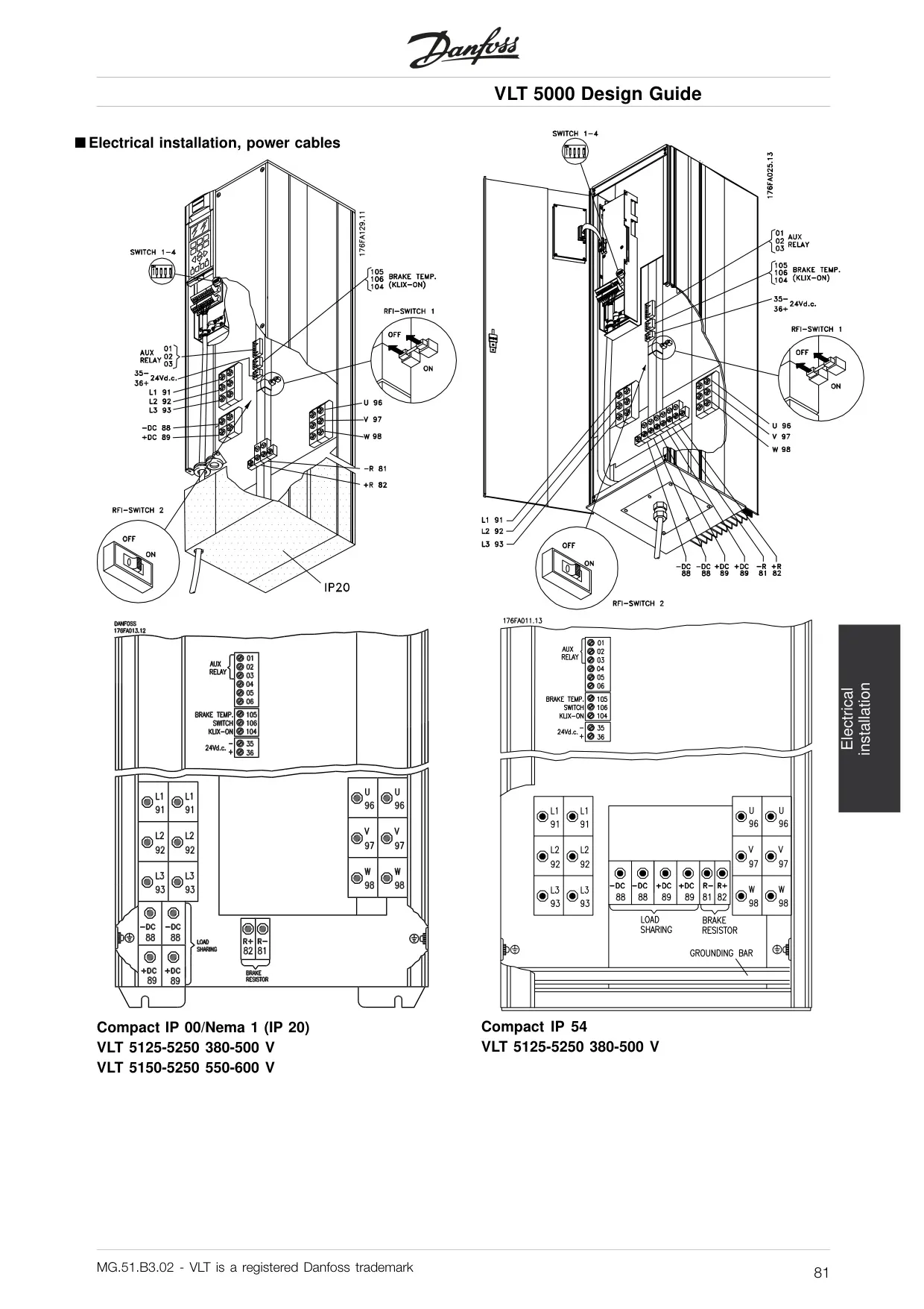
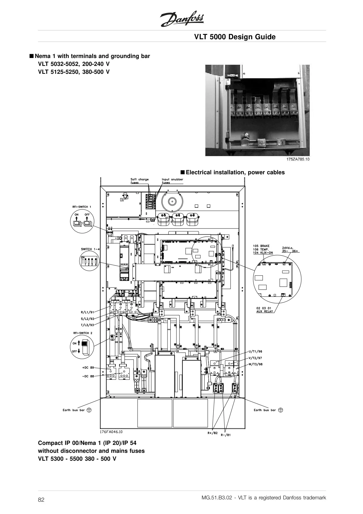
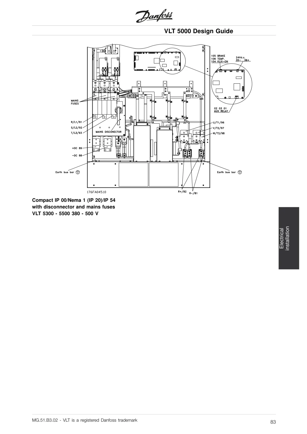
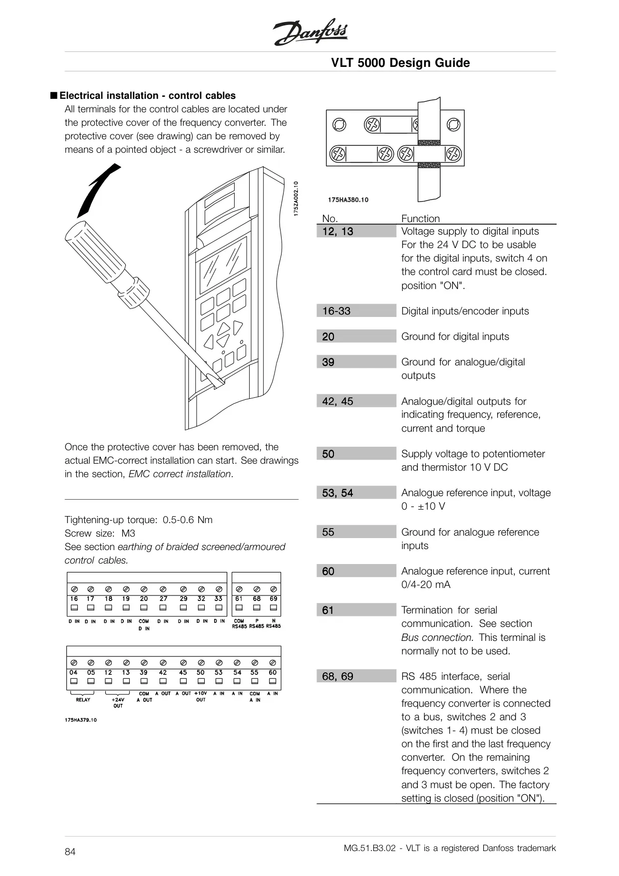
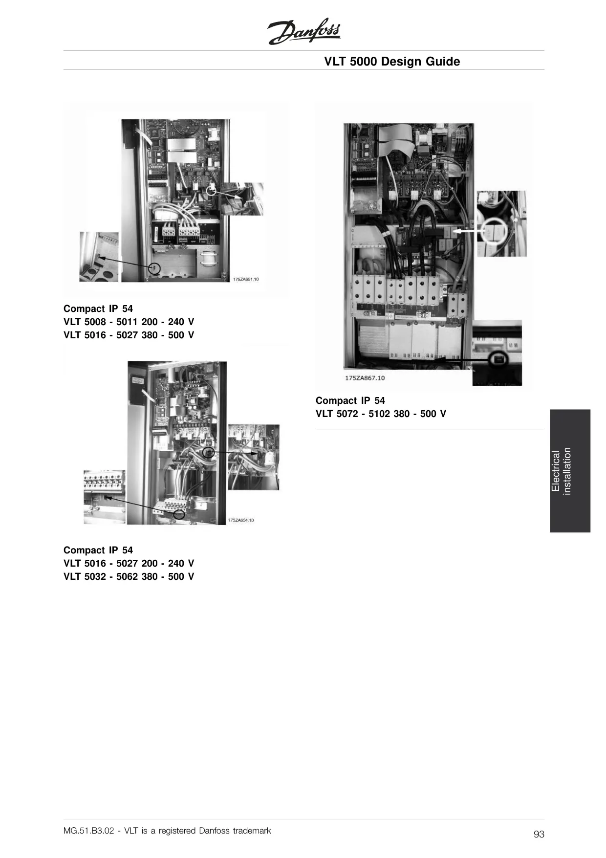
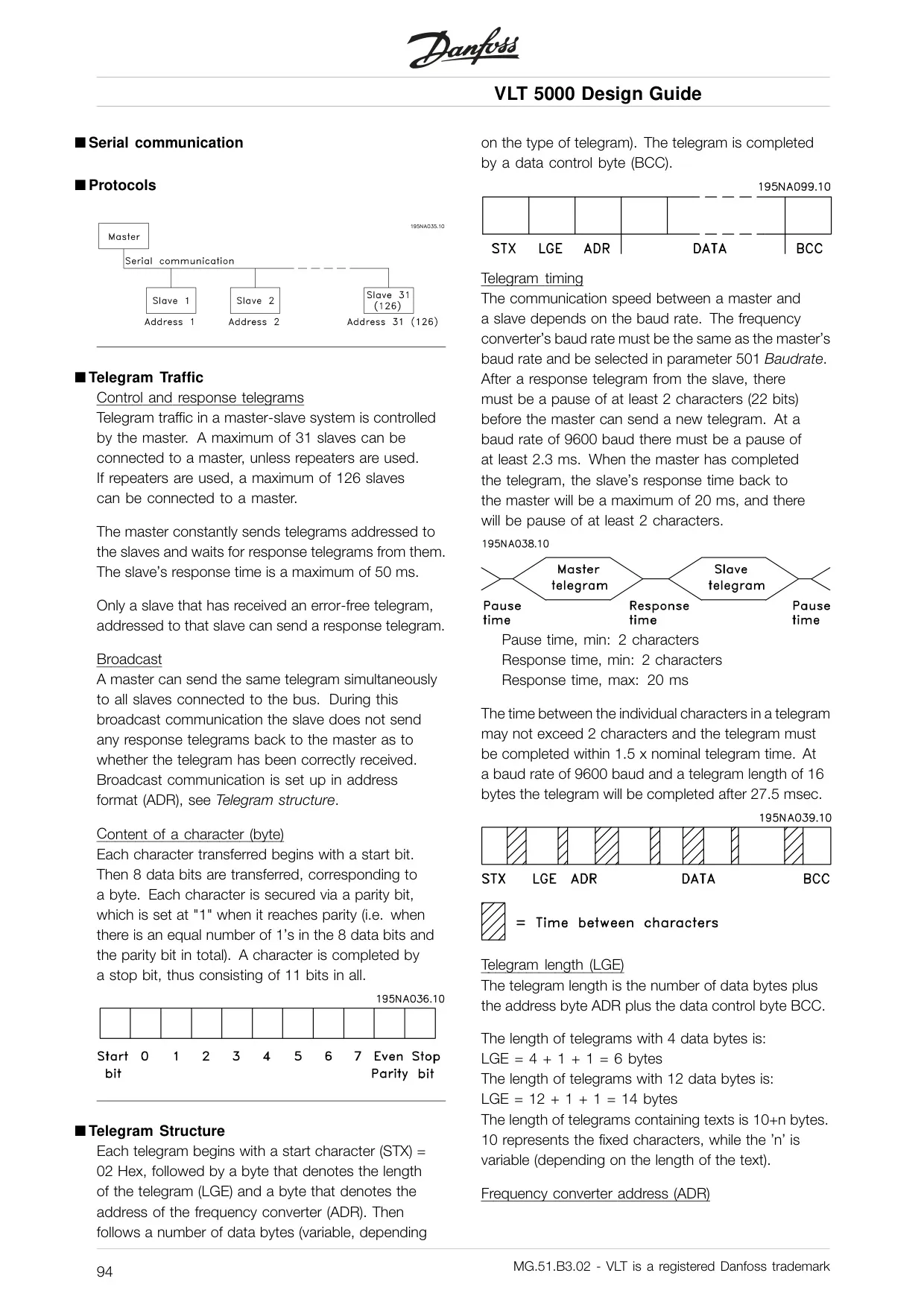
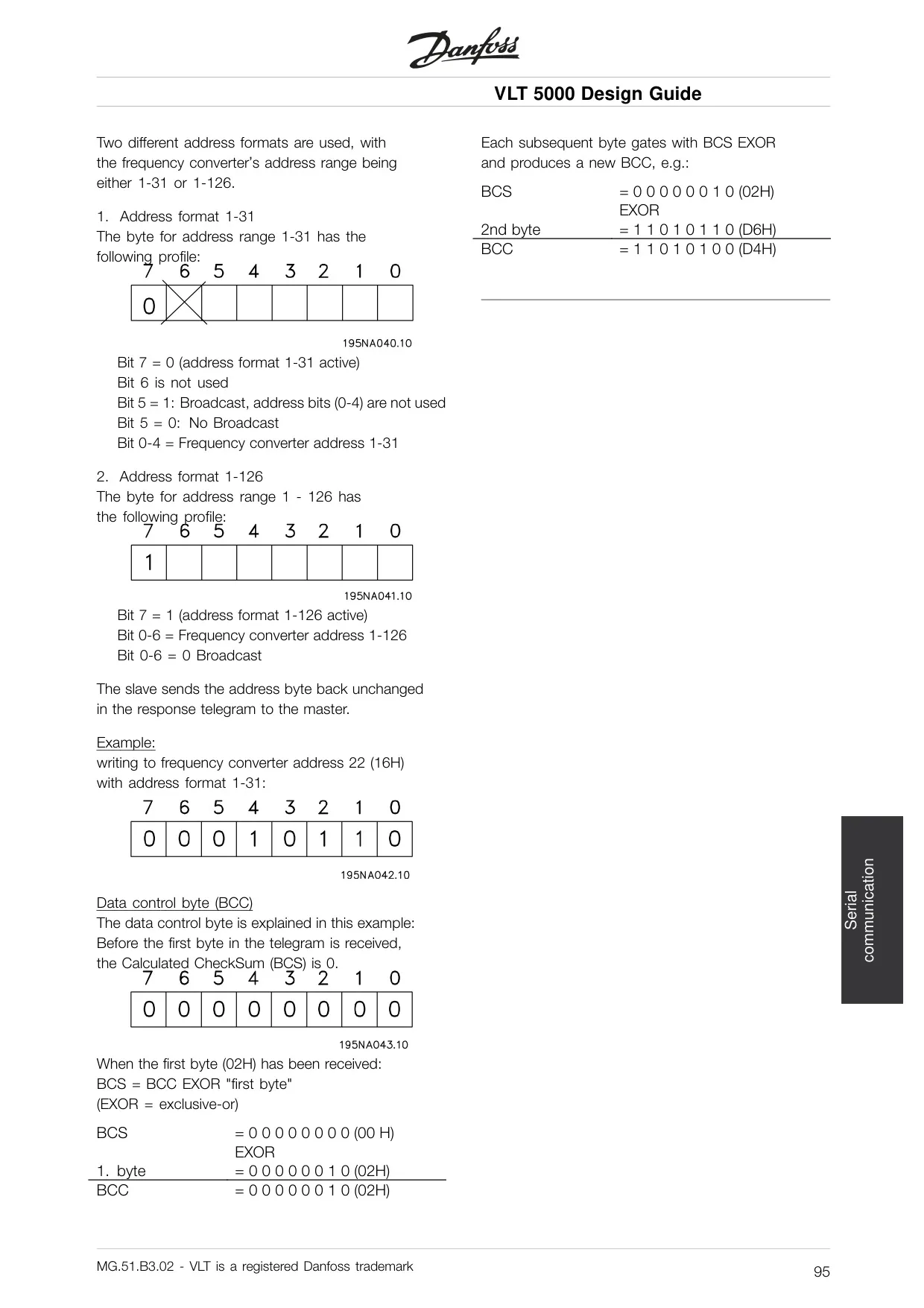
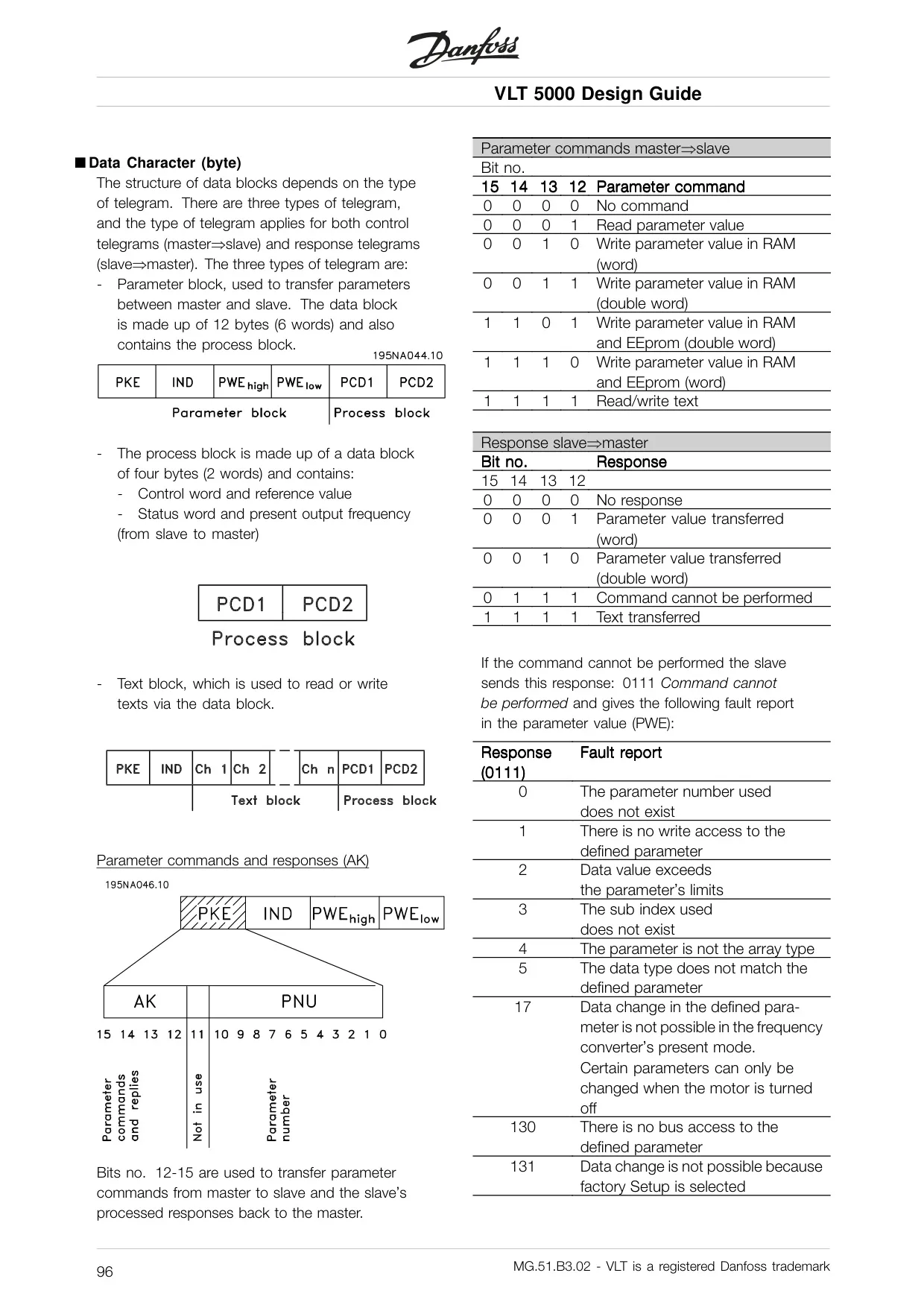
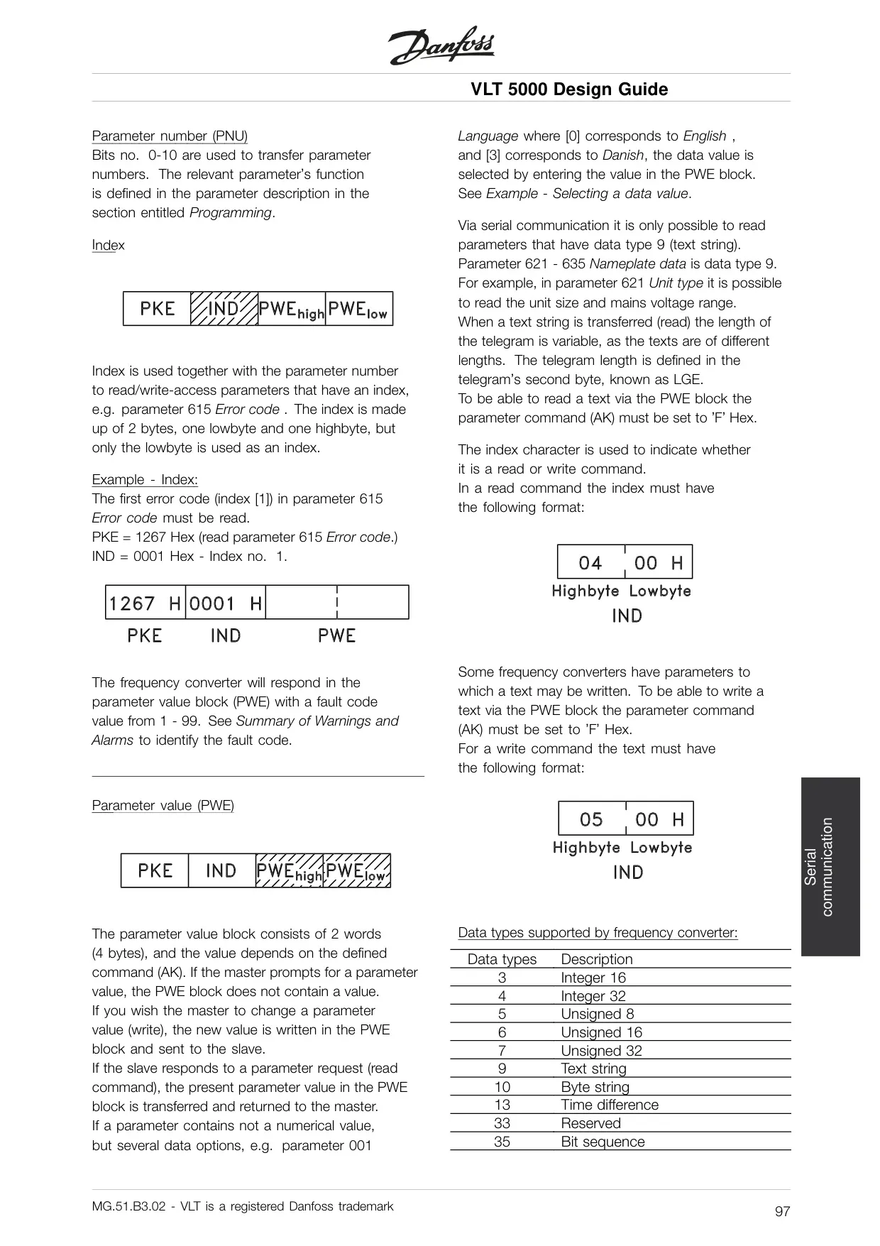
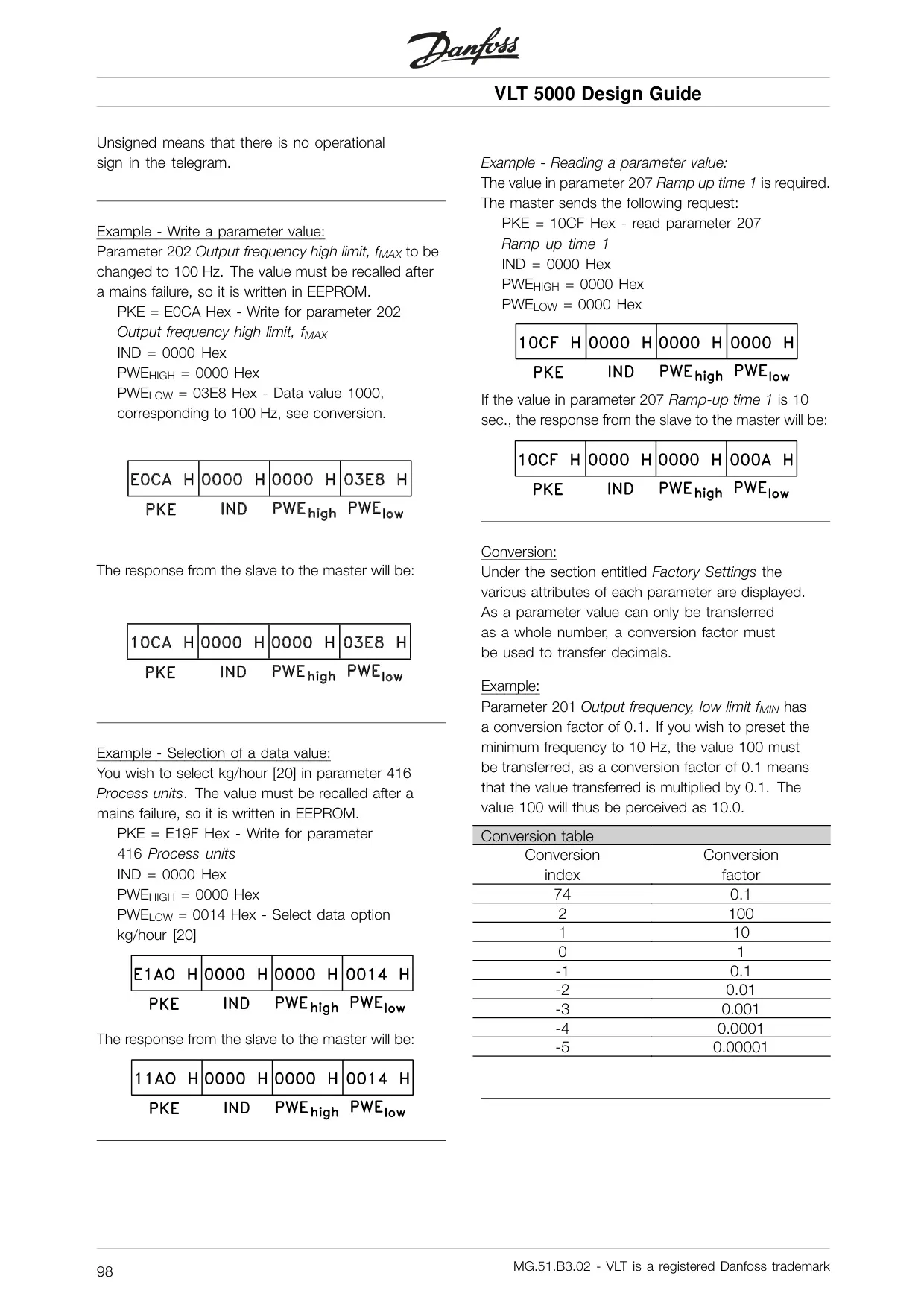
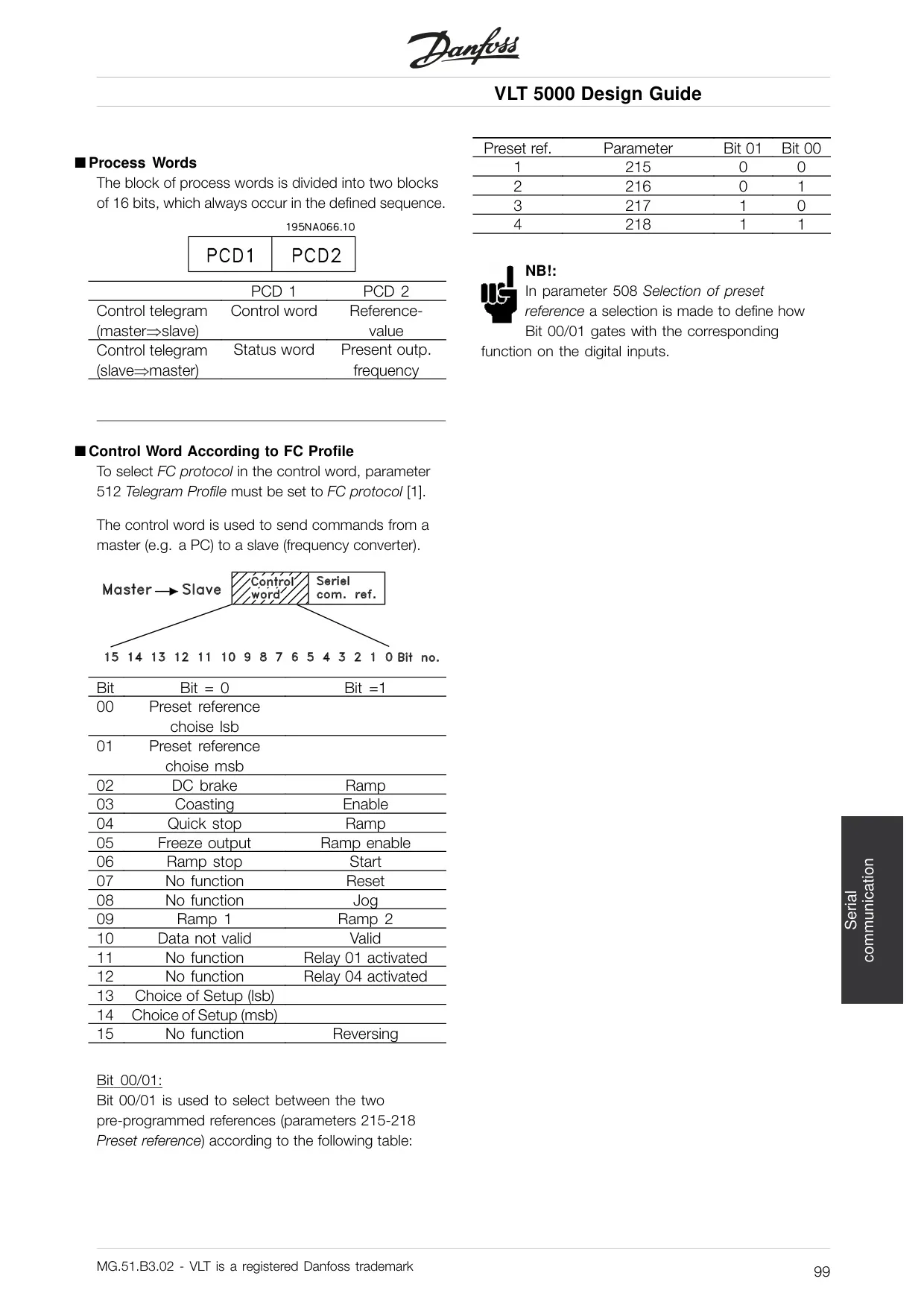
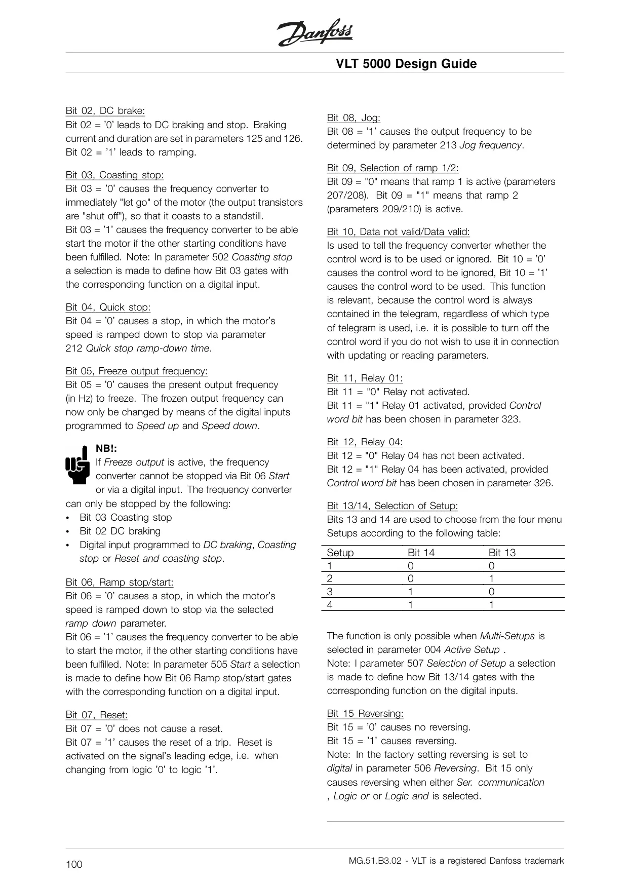
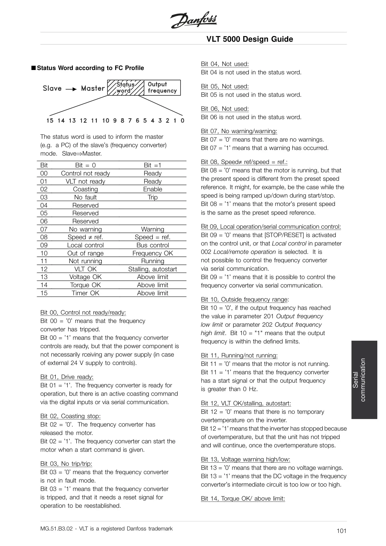
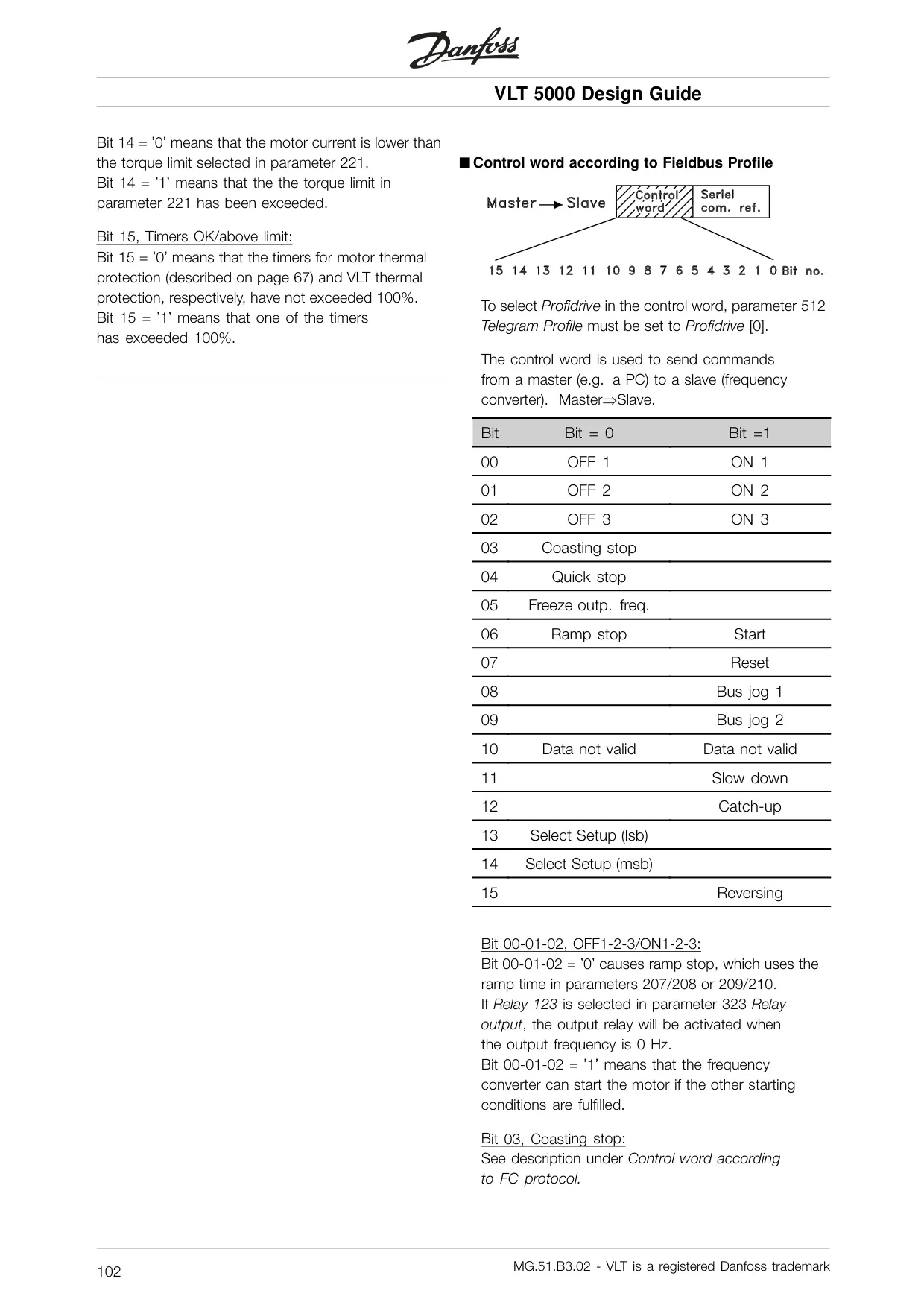
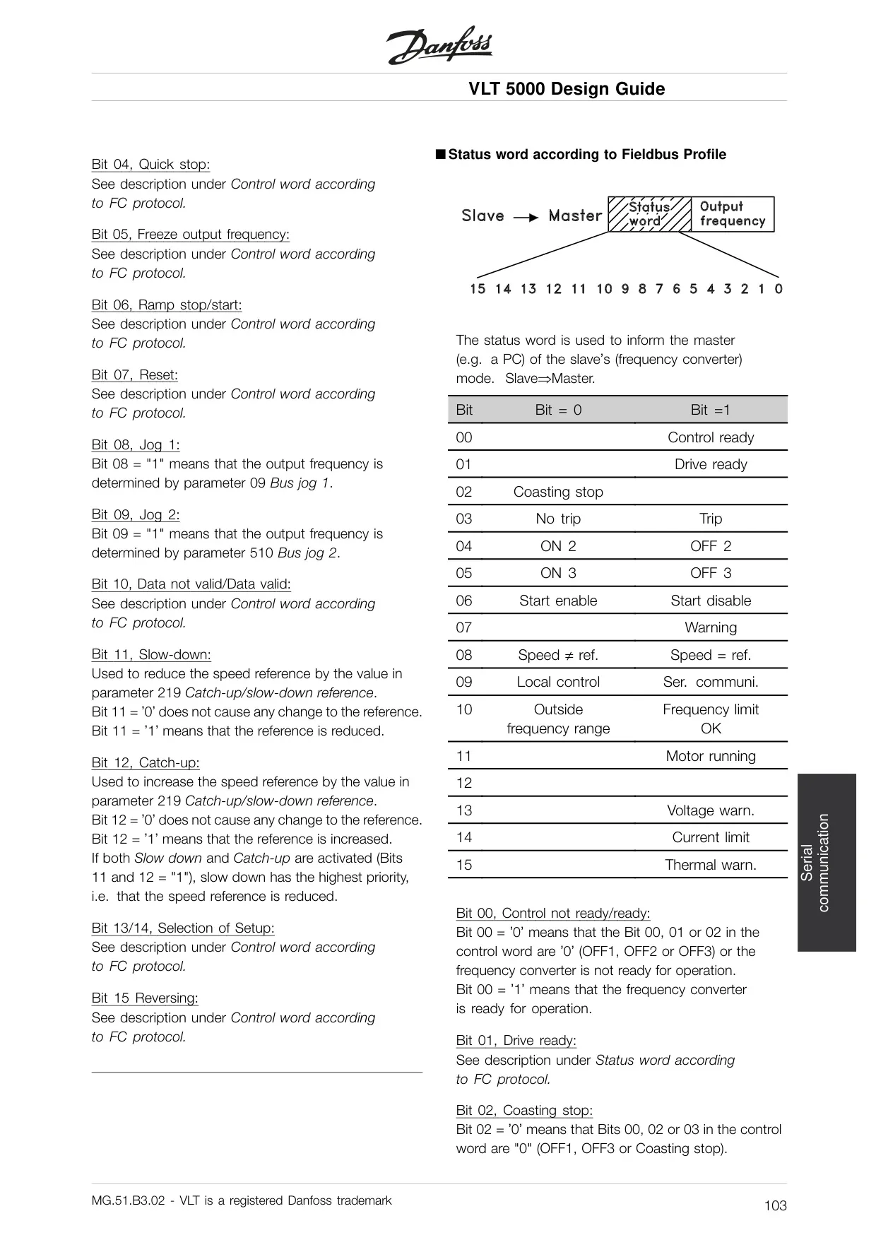
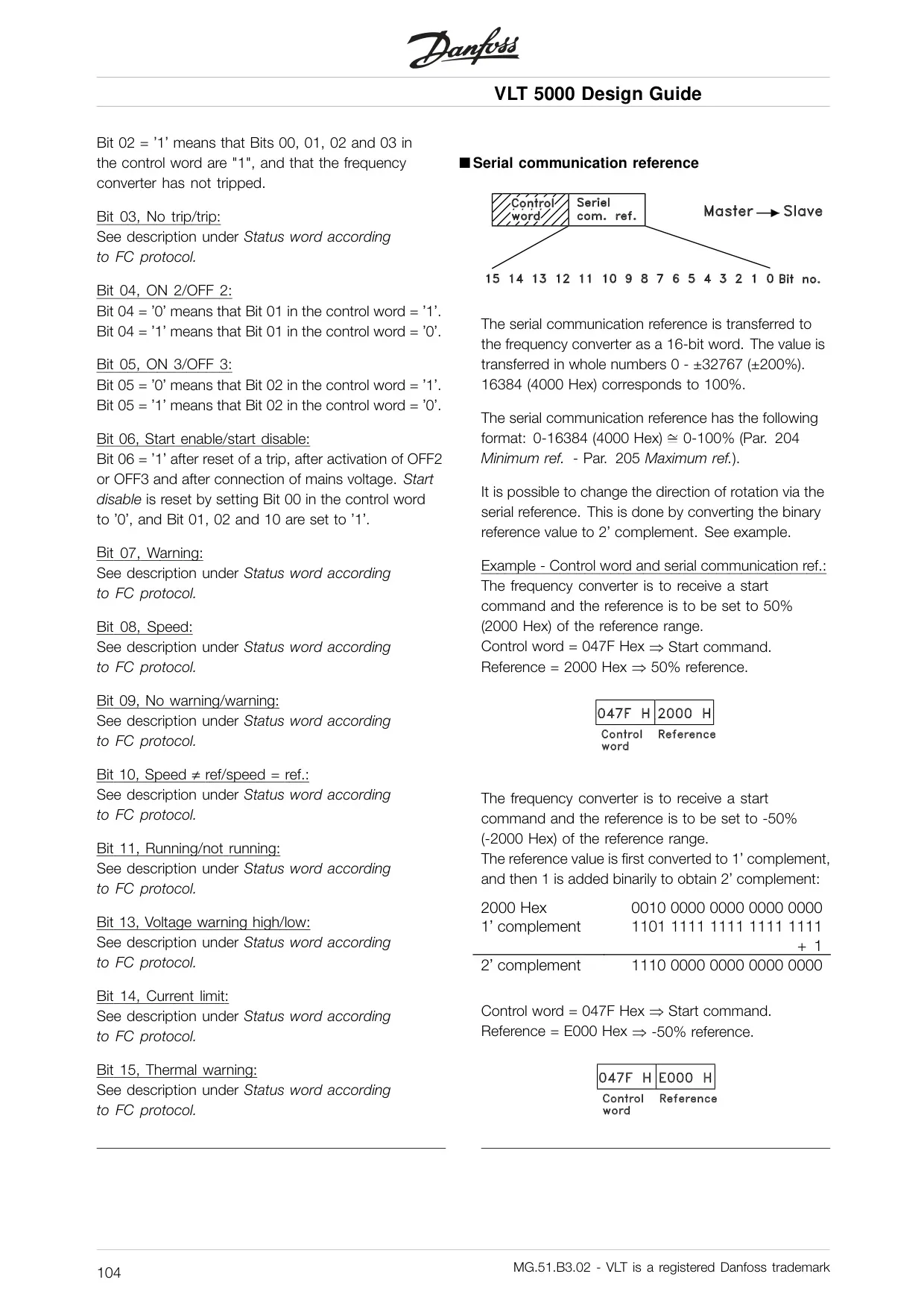
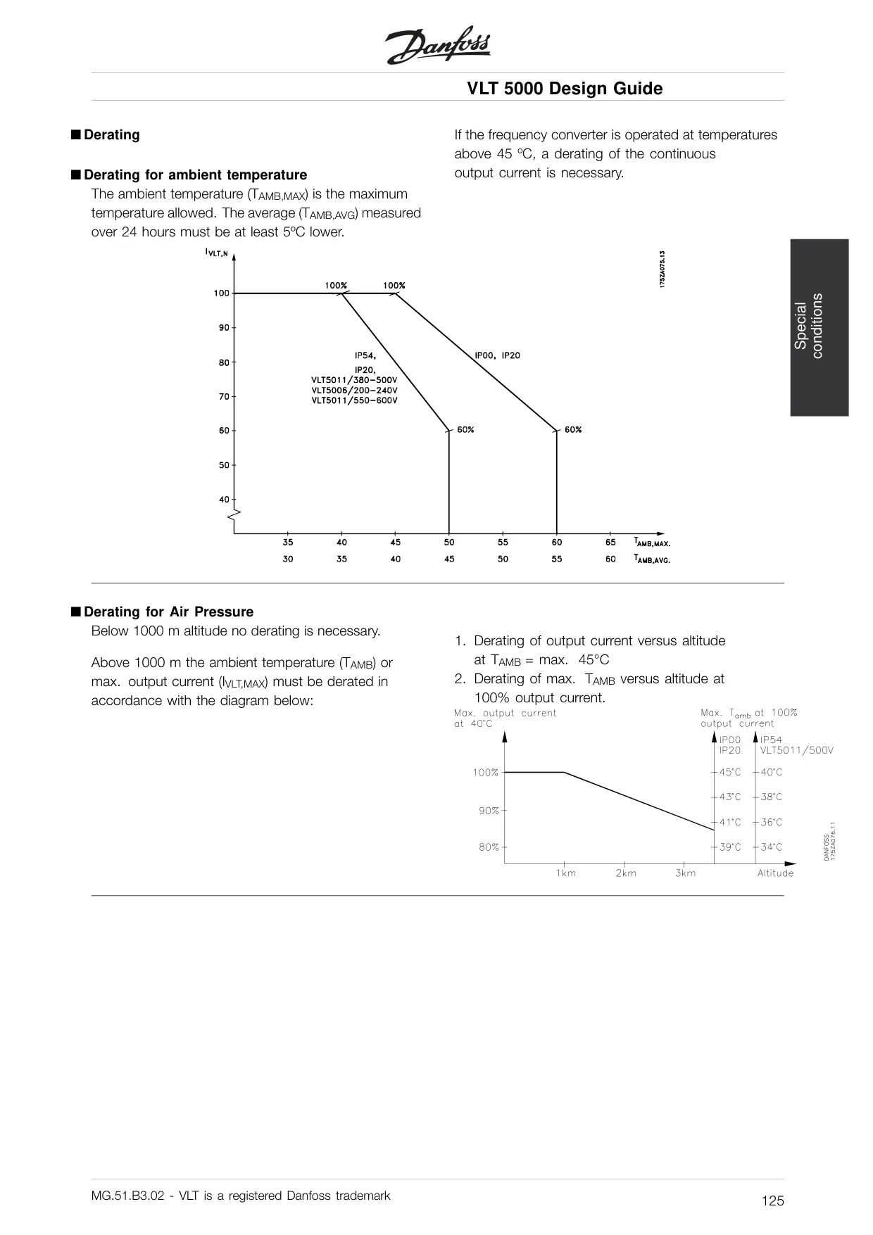
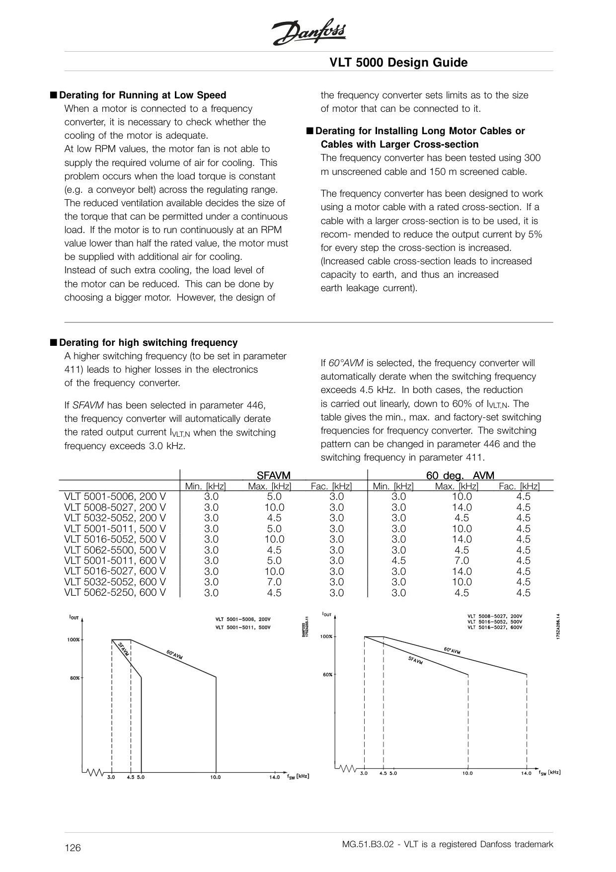
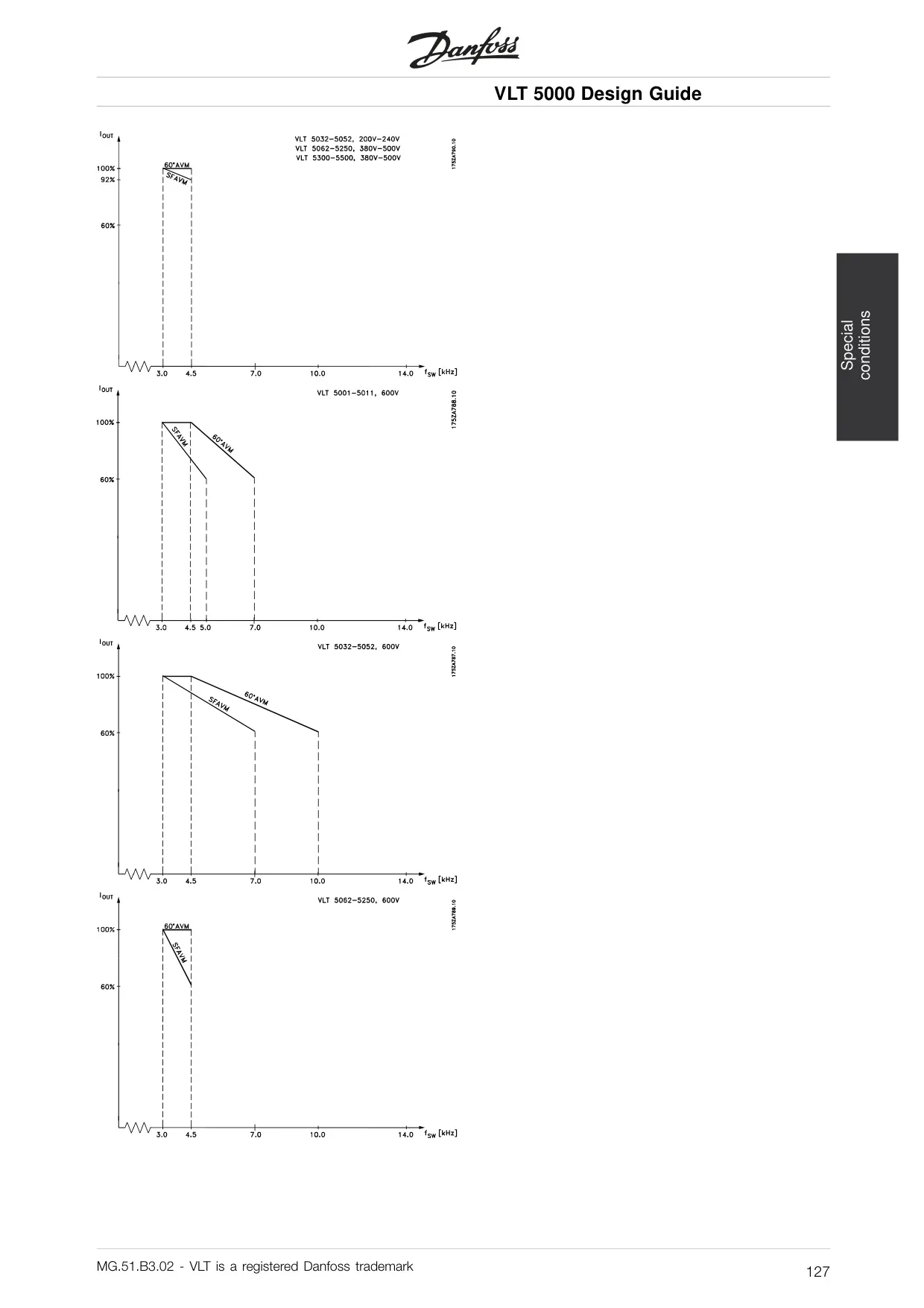
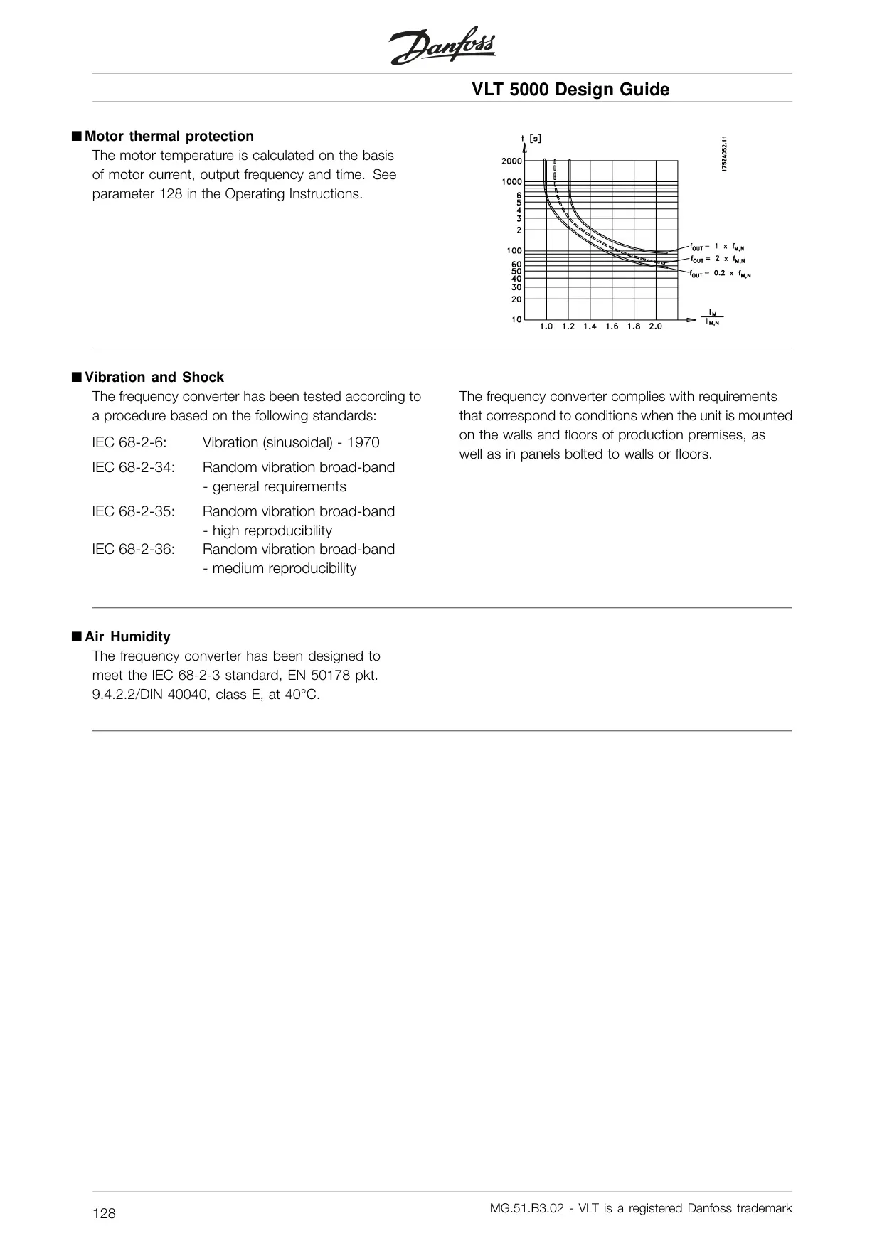
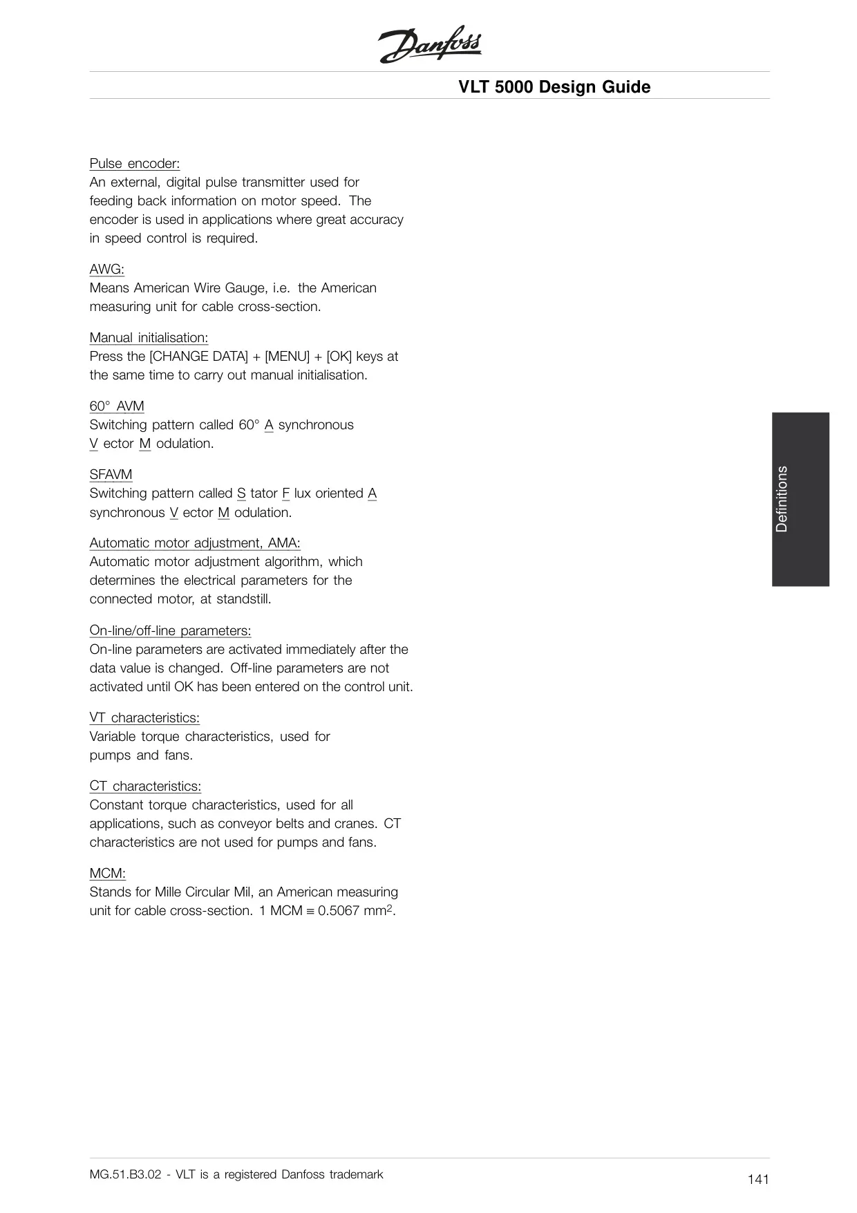
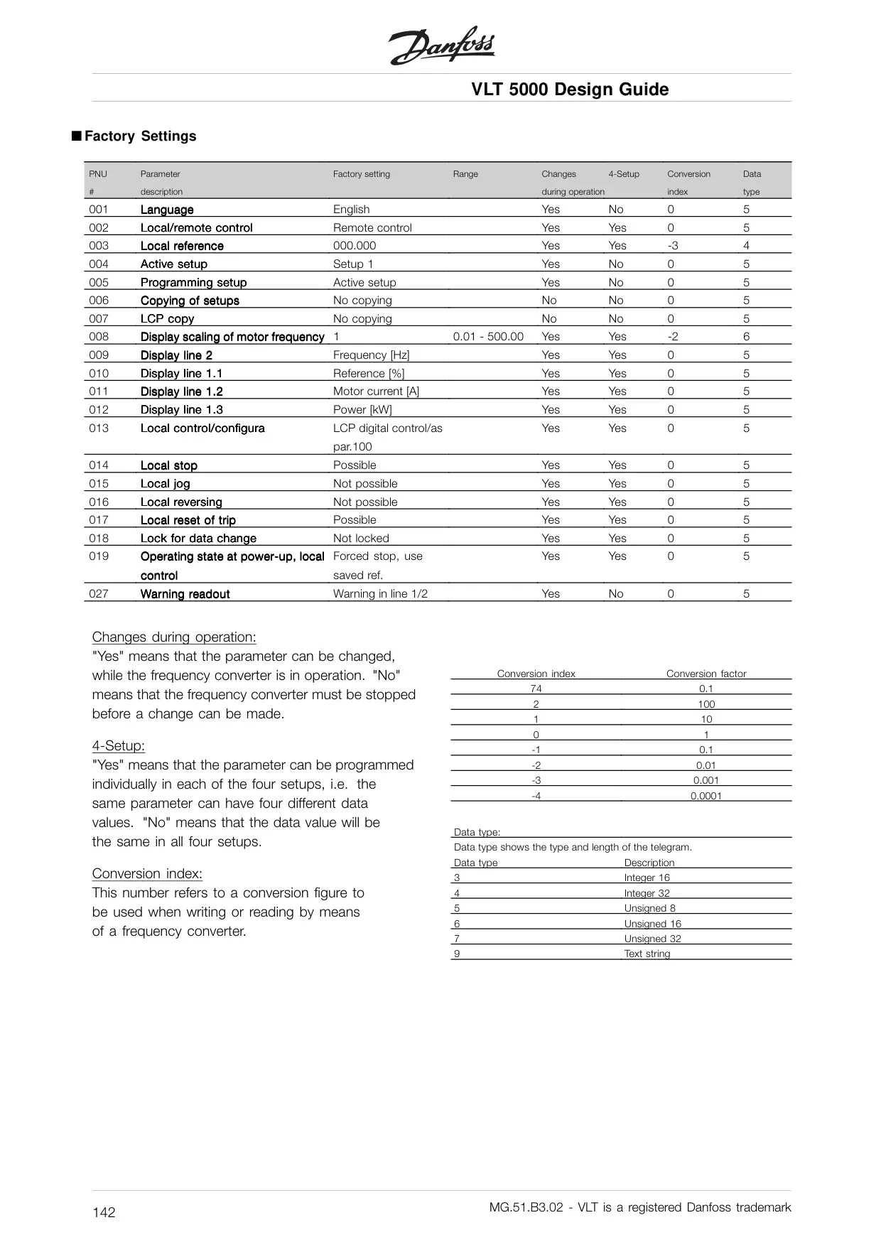
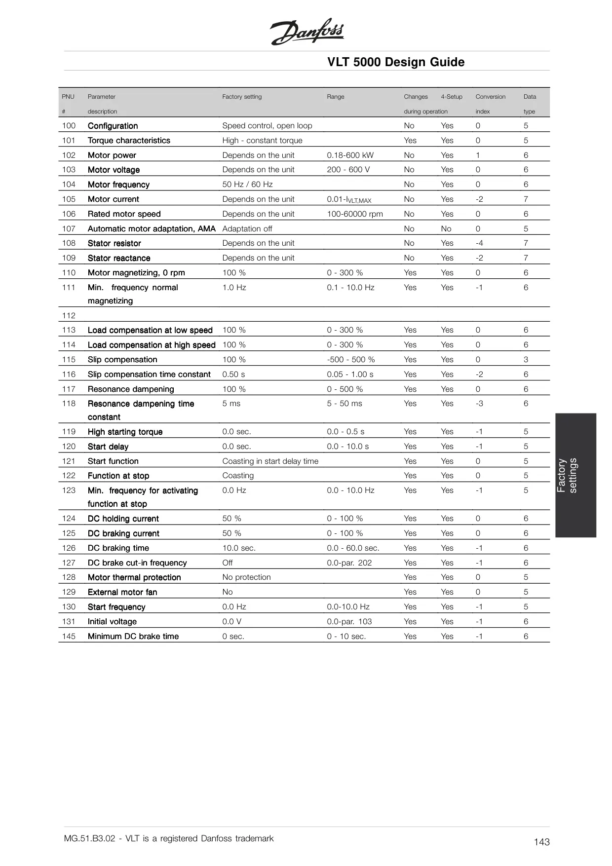
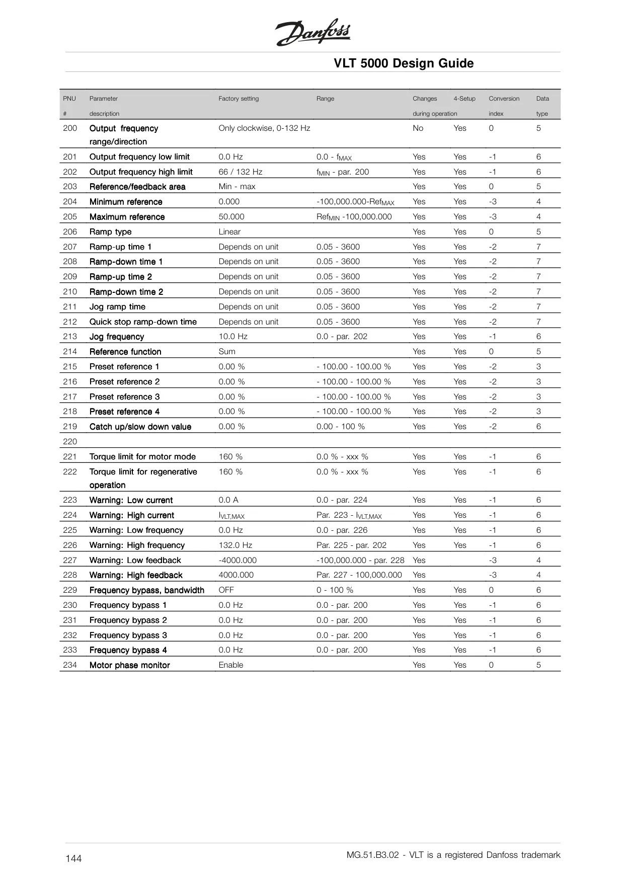
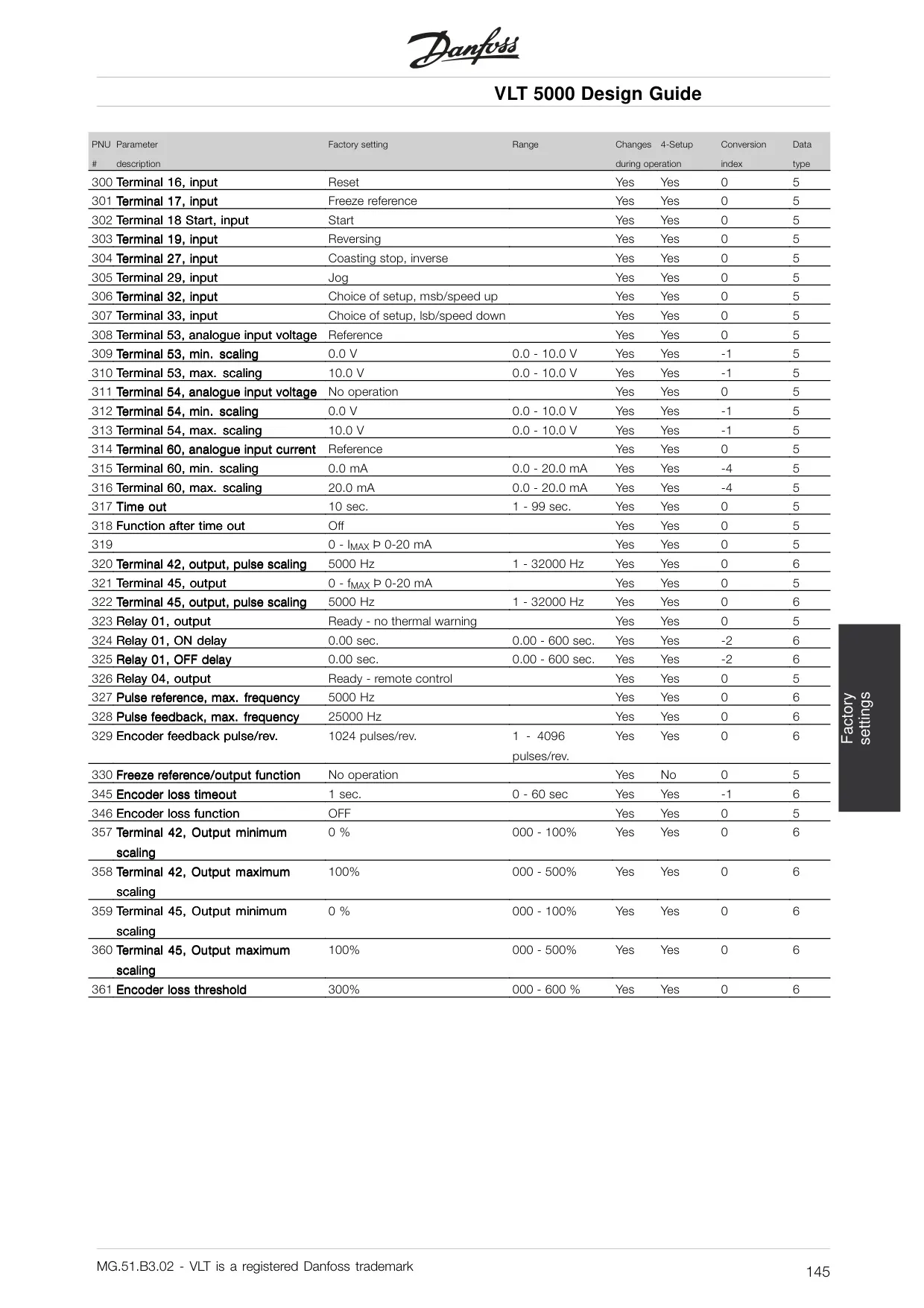
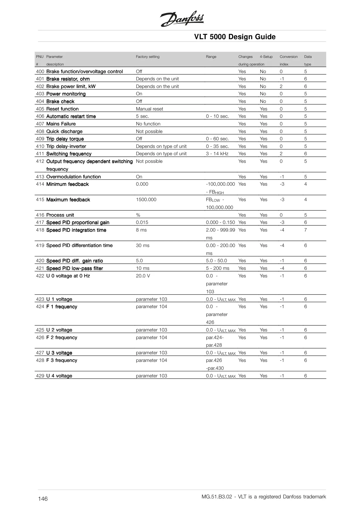
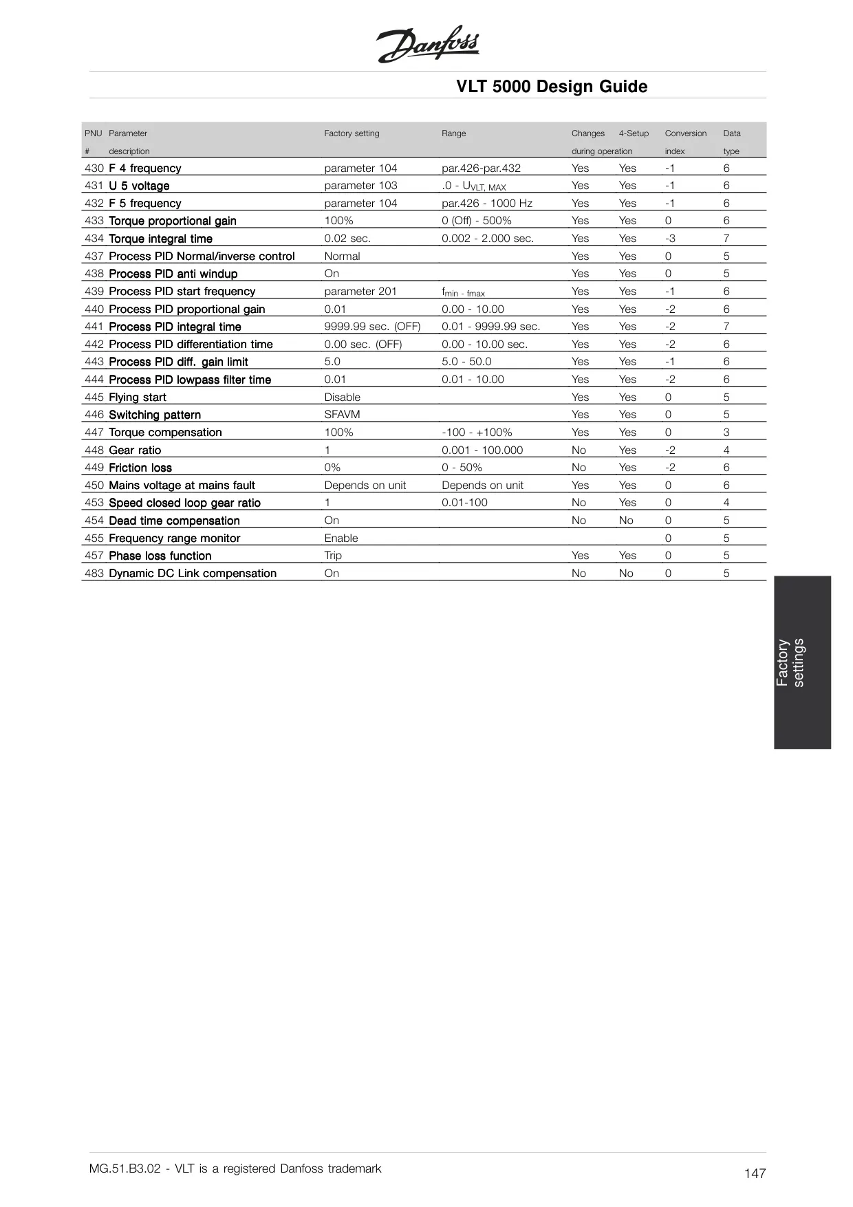
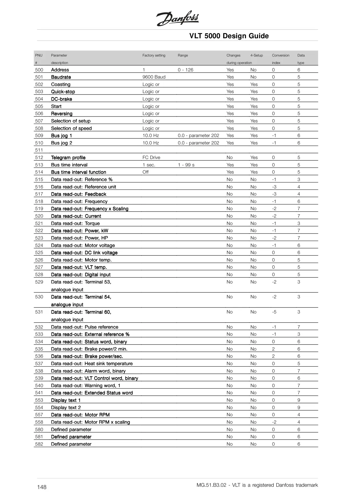
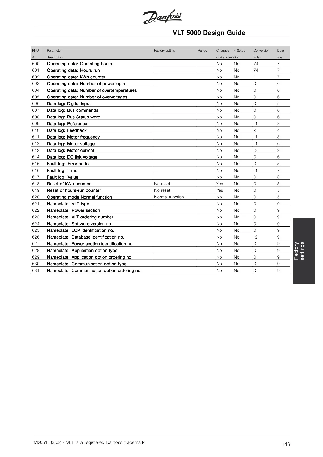
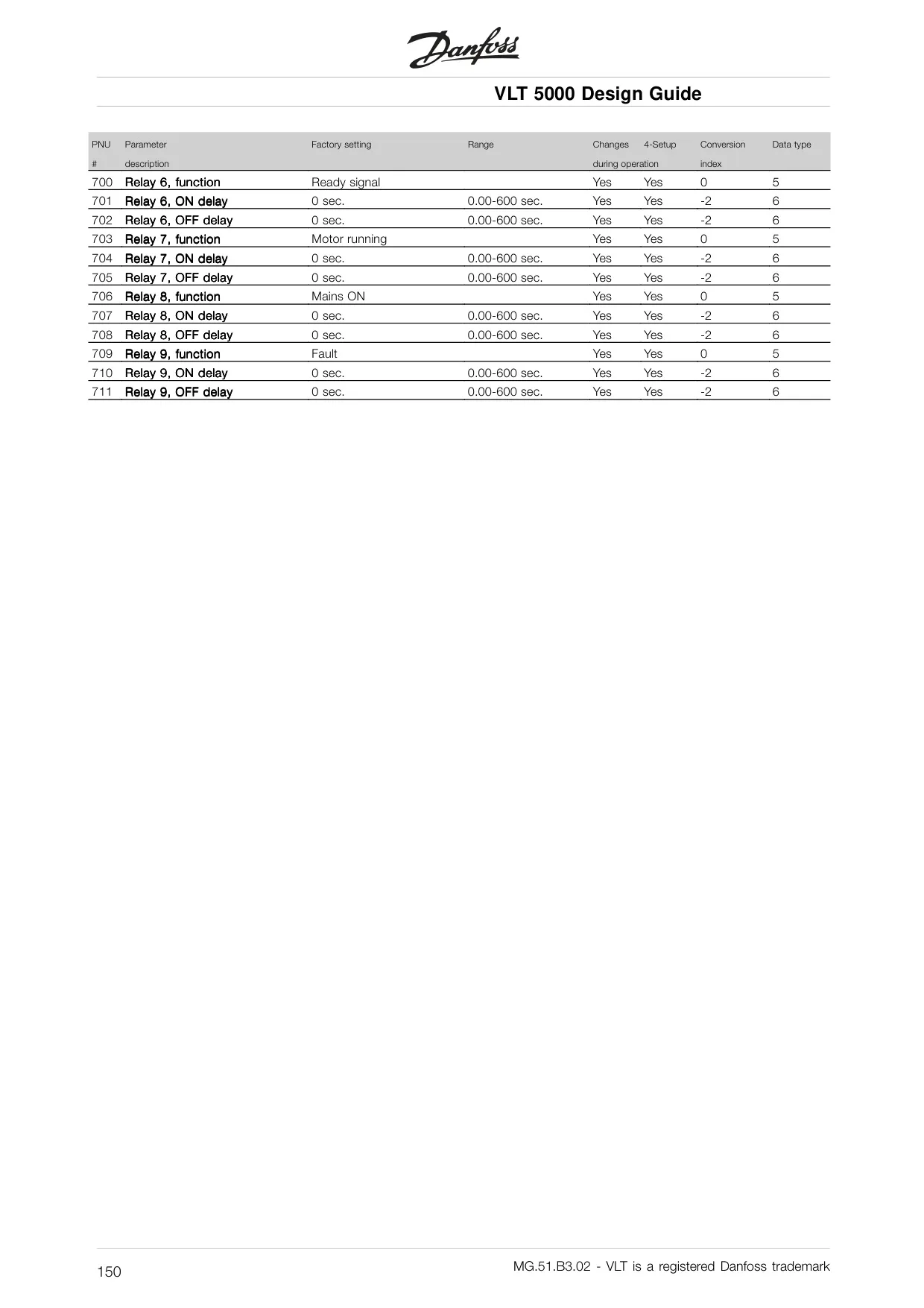
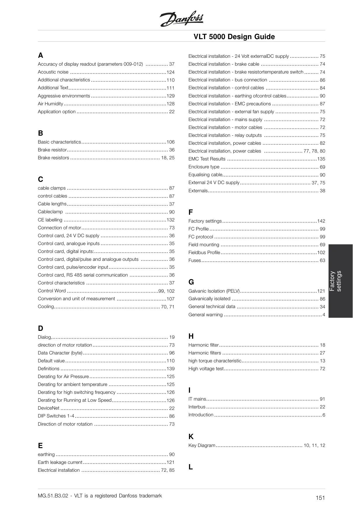
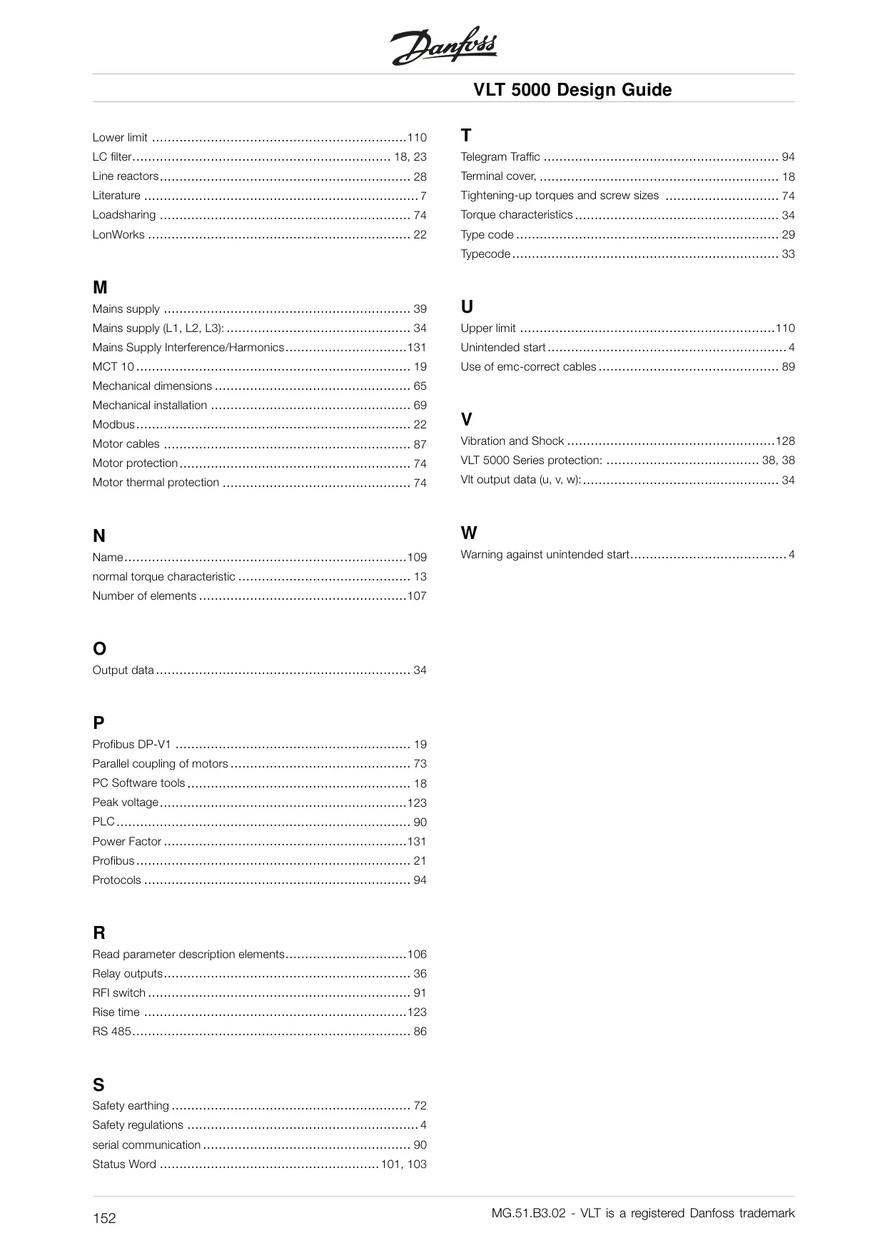
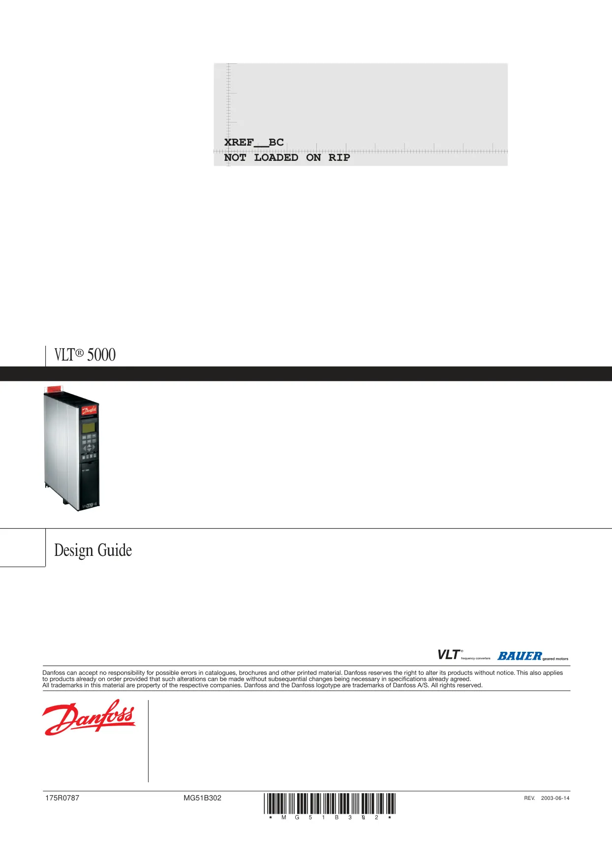
Danfoss VLT 5000 Variable Frequency Drive
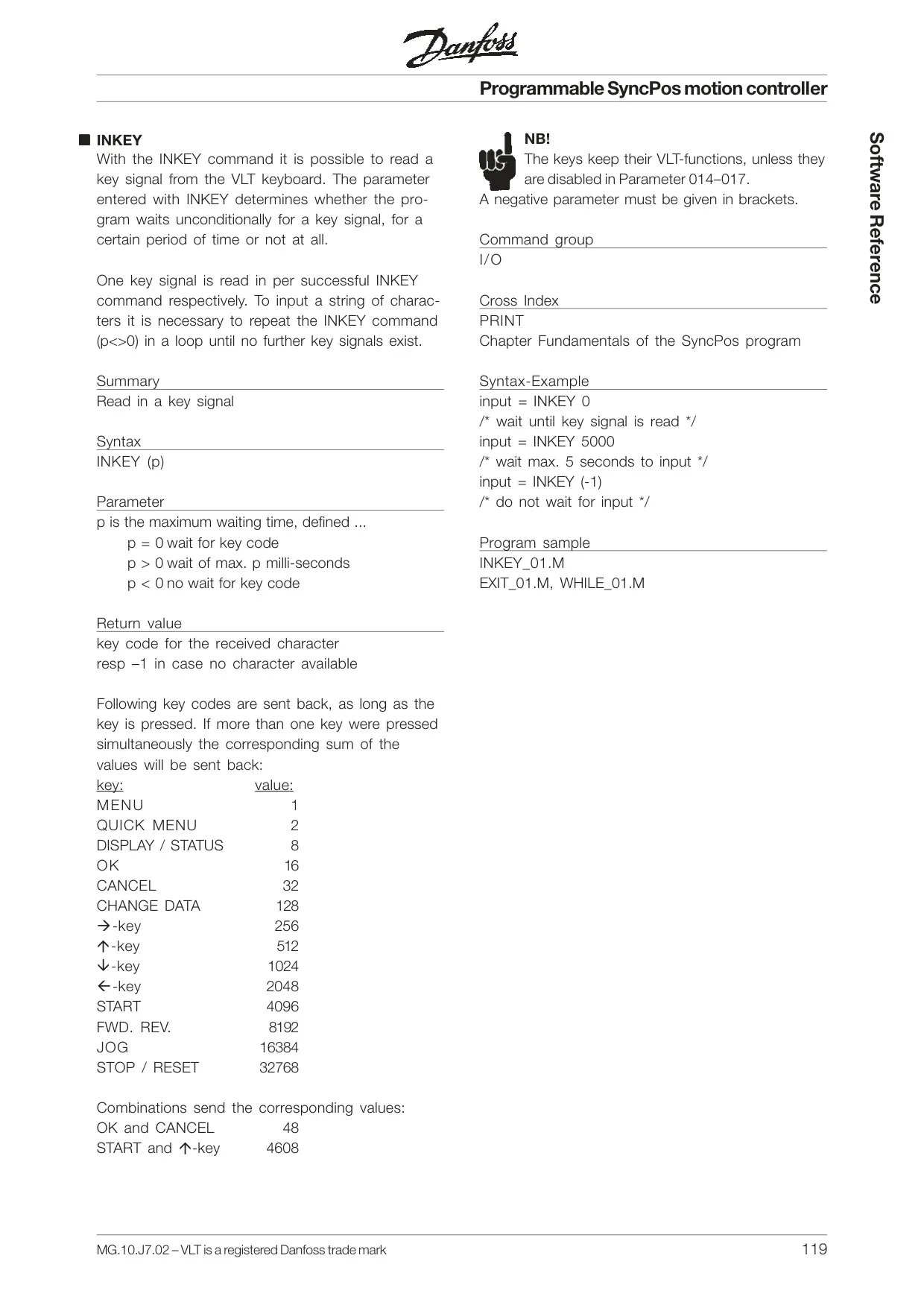
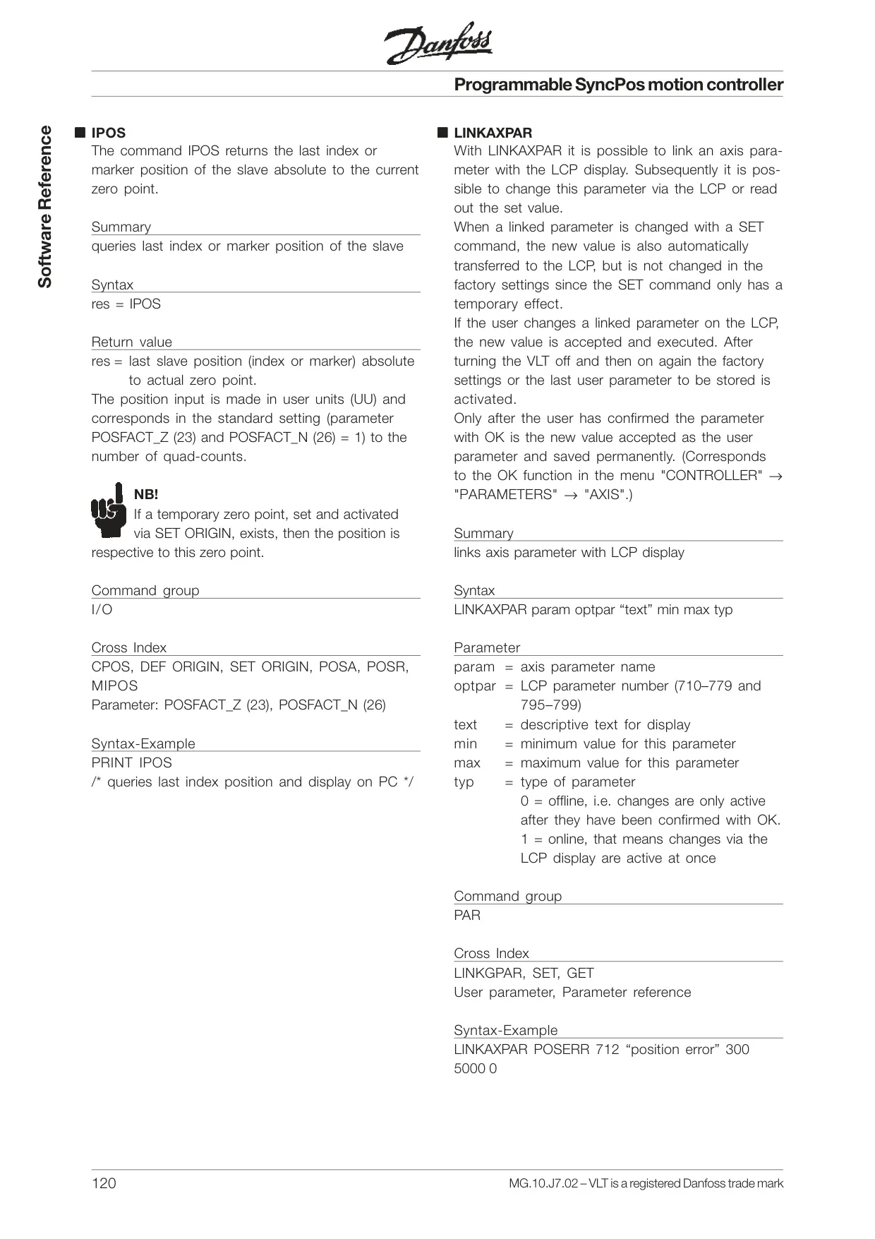
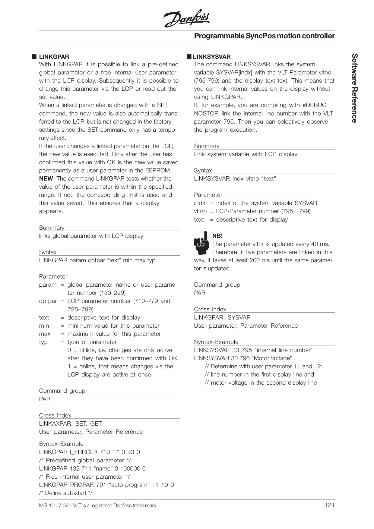
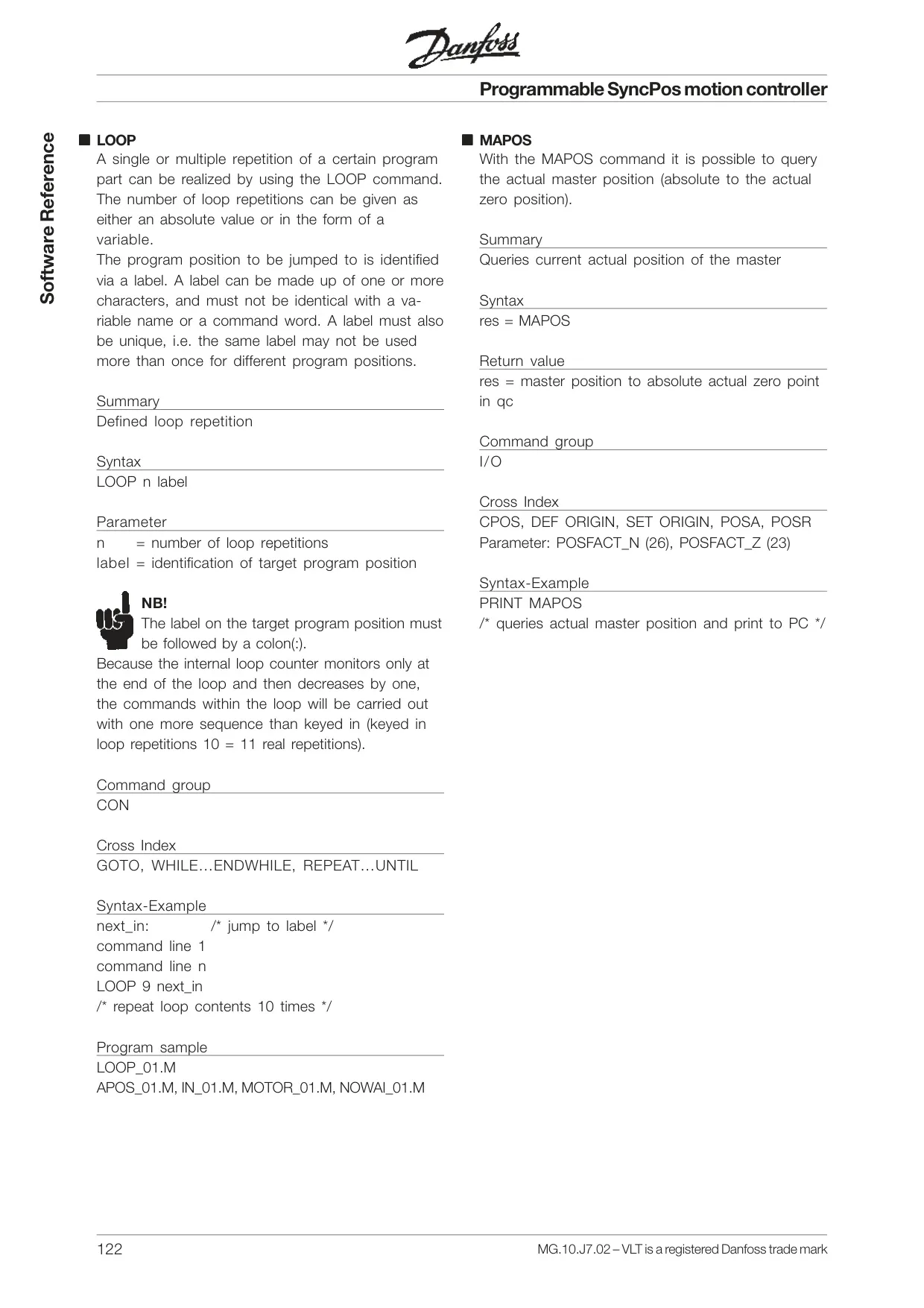
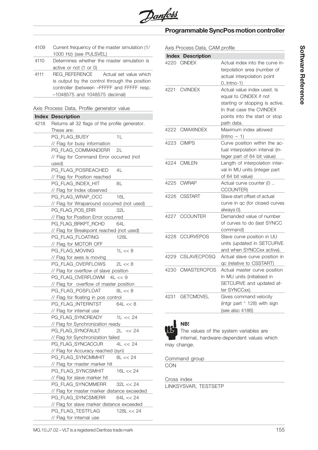
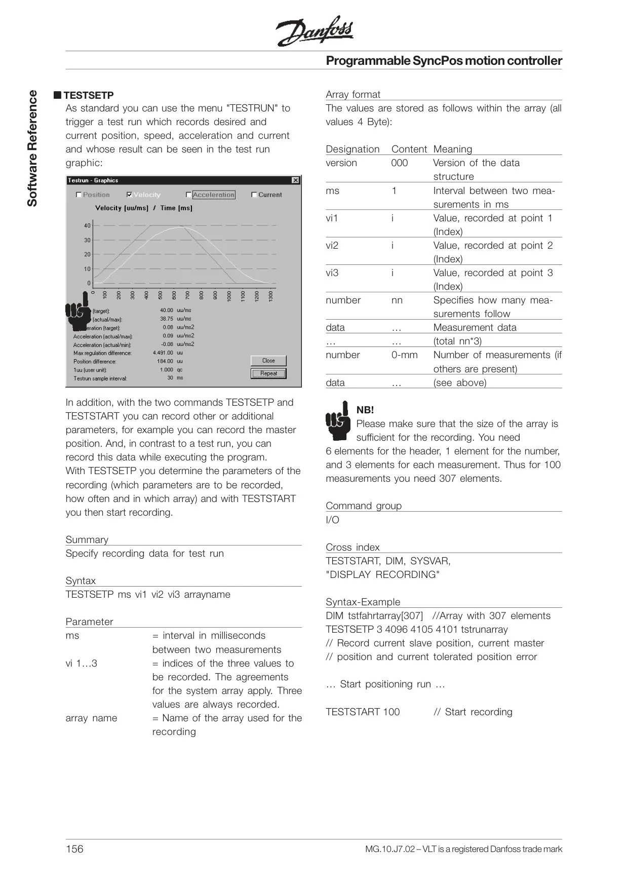
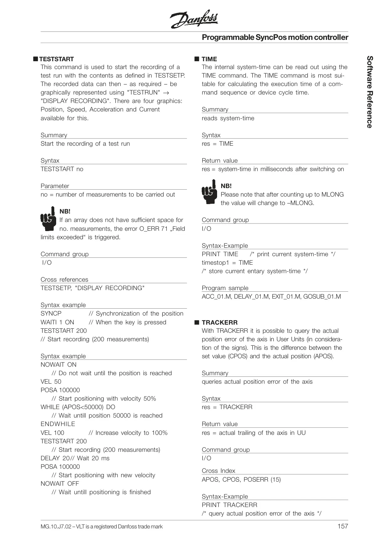
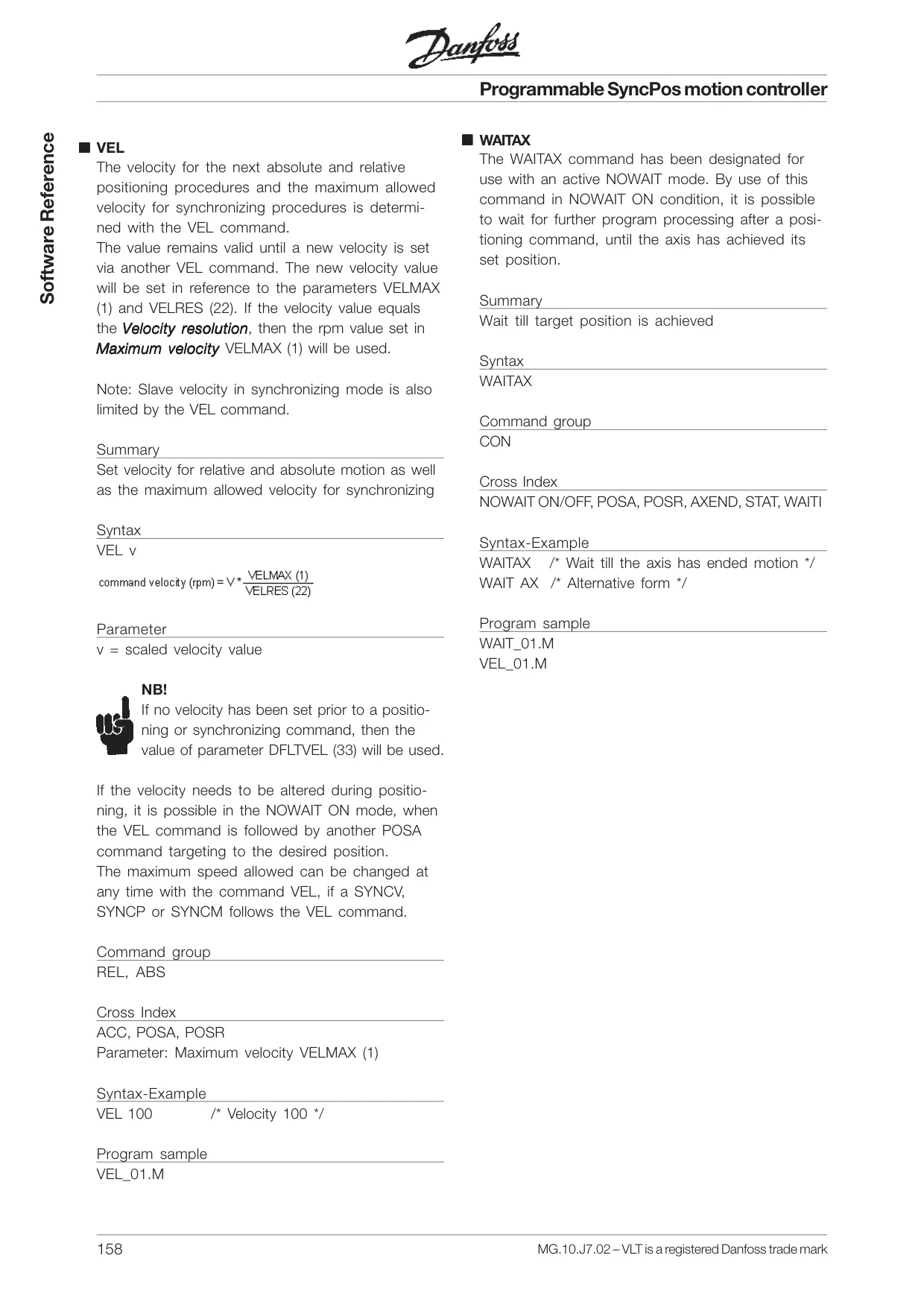
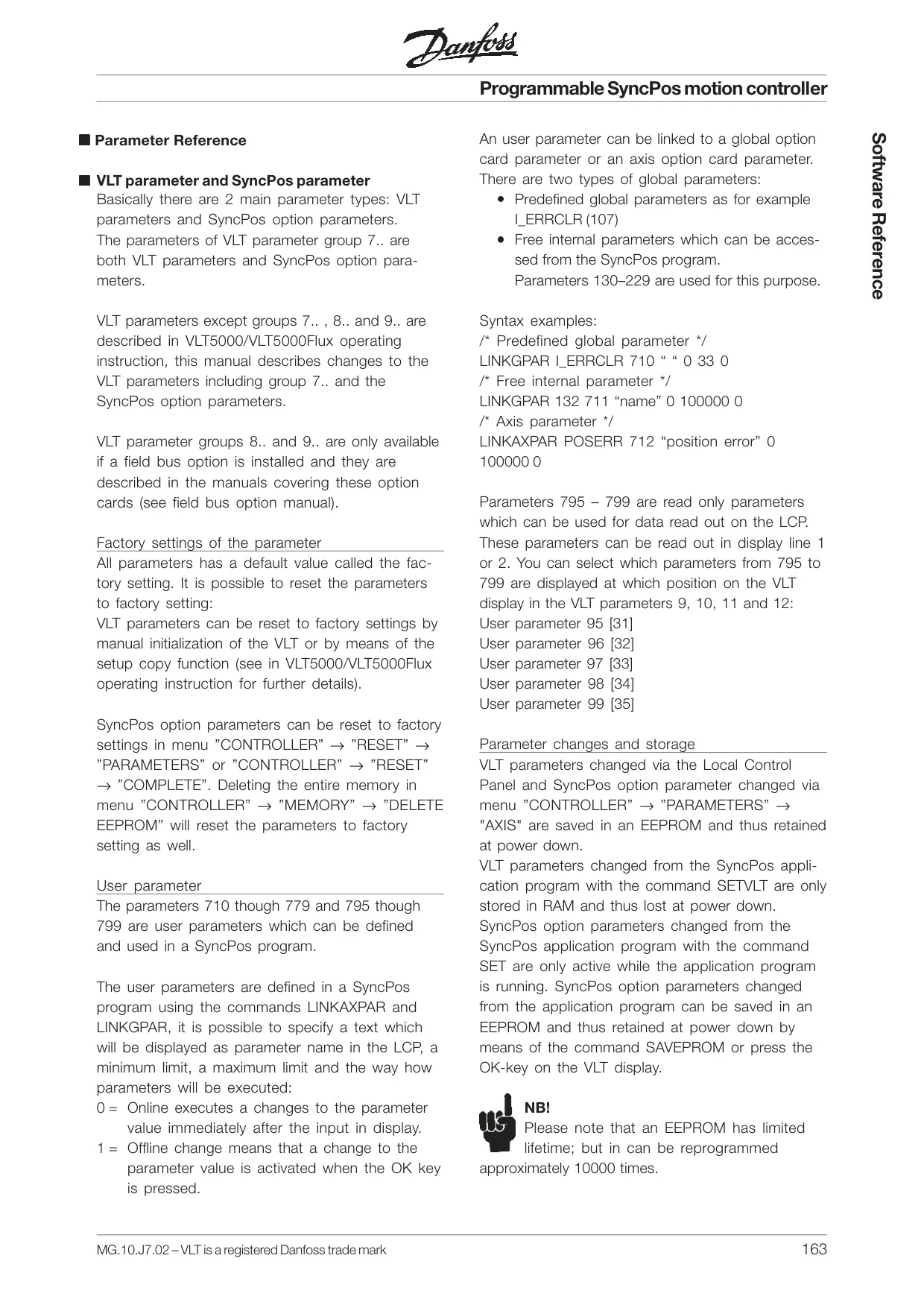
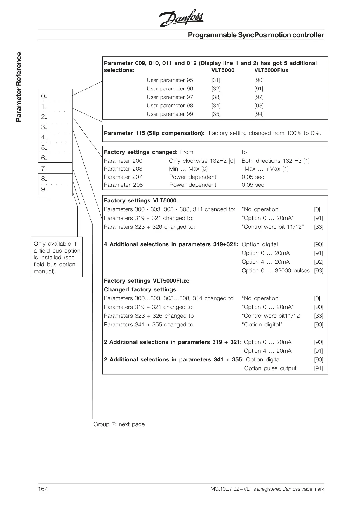
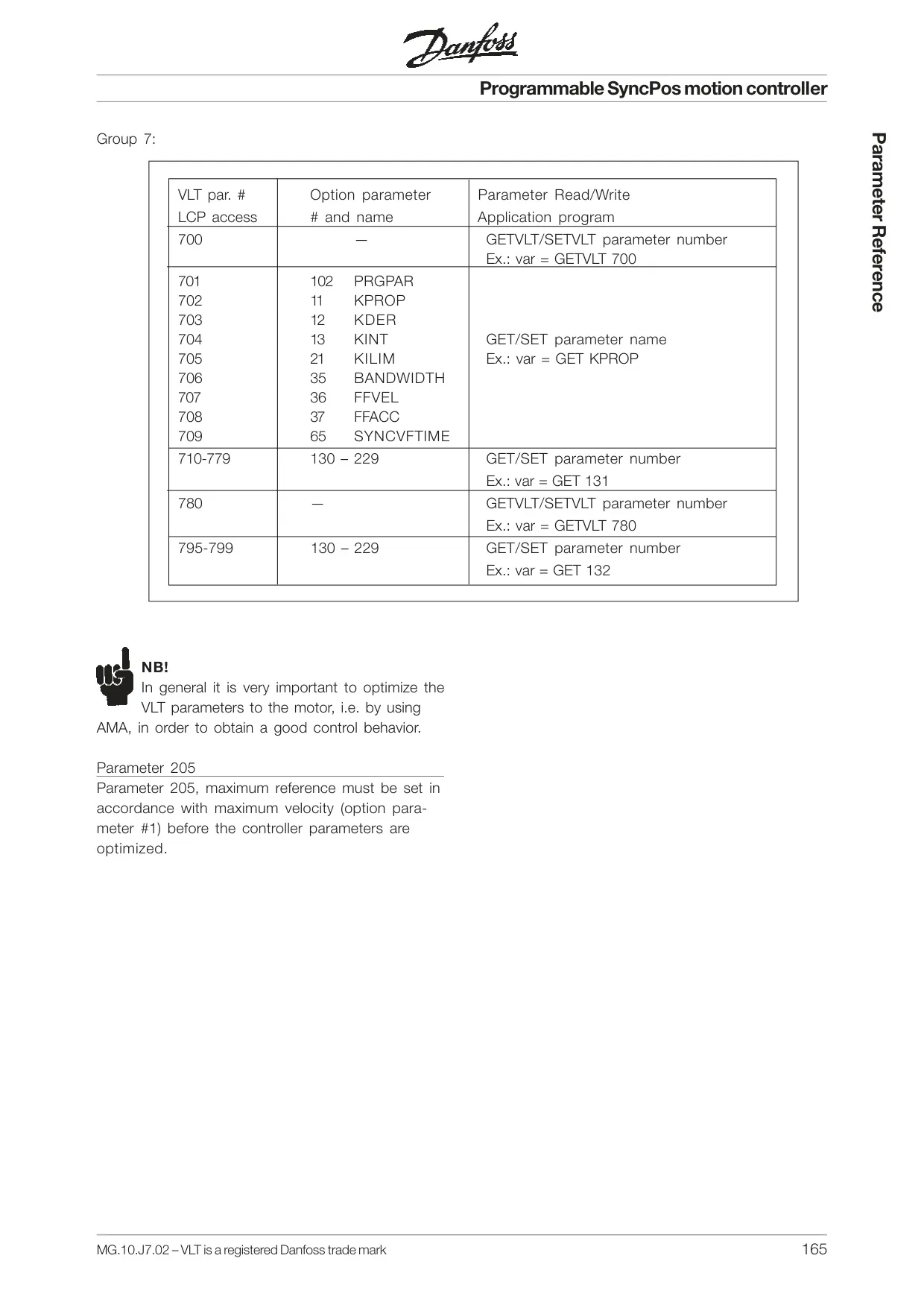
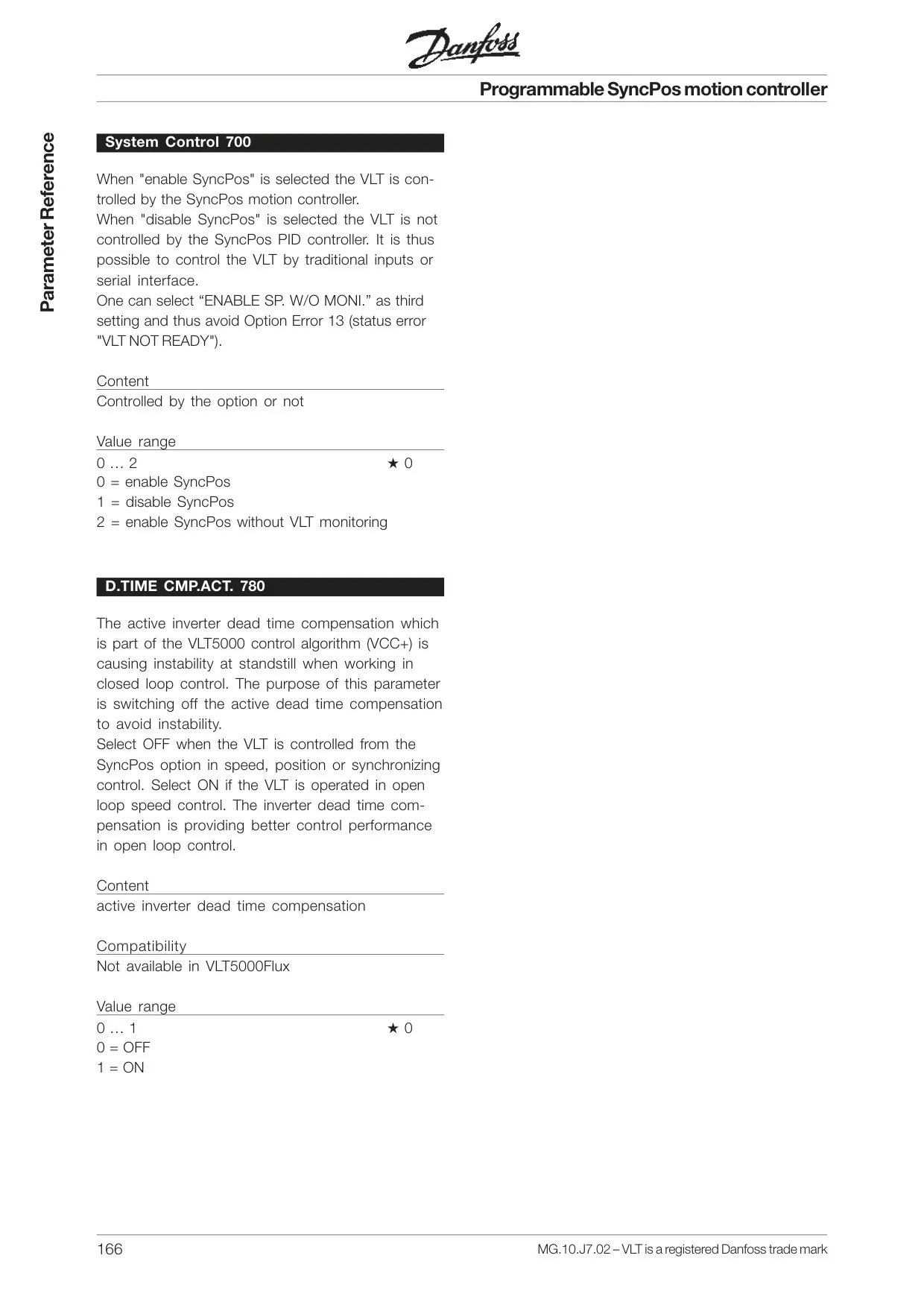
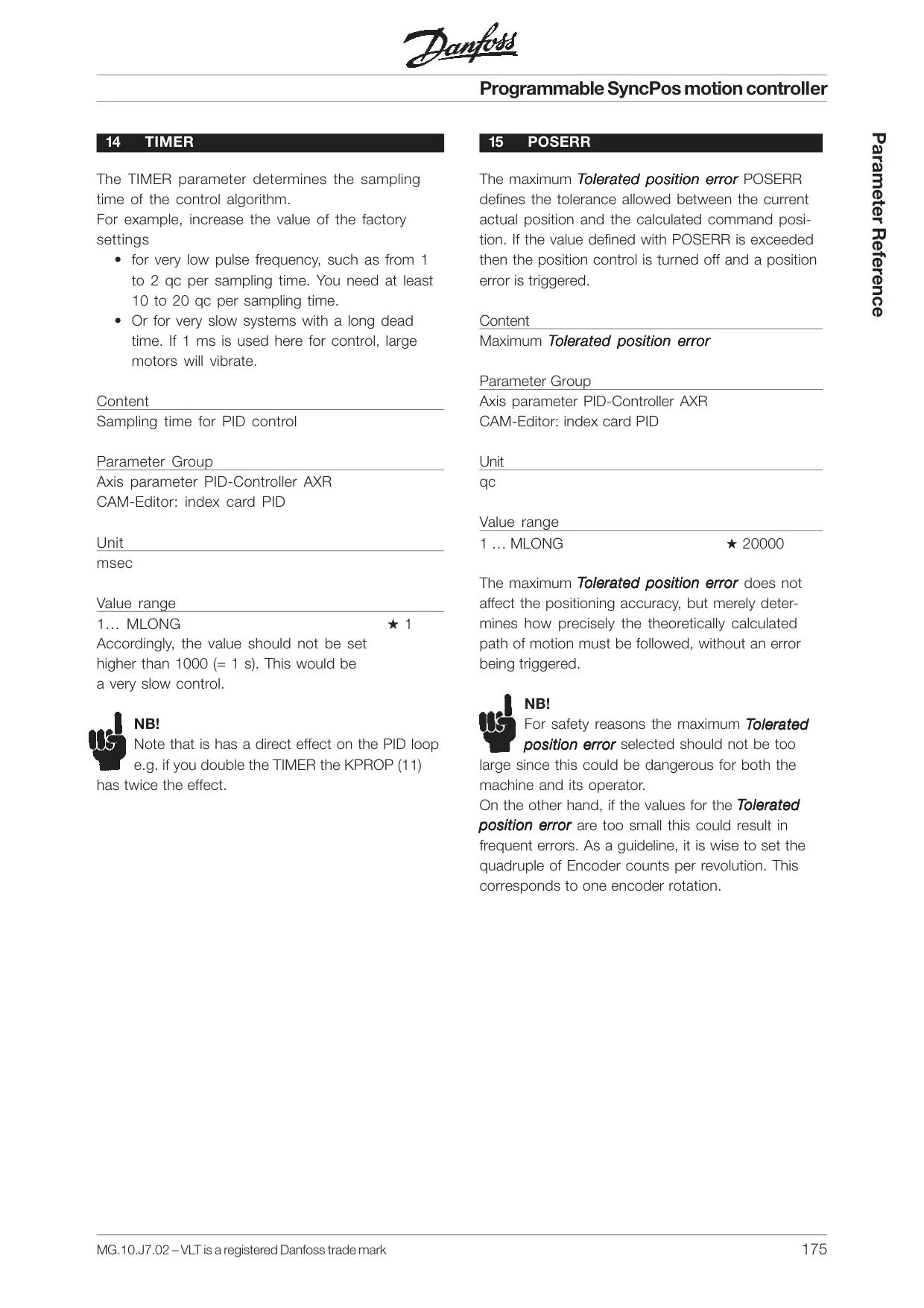
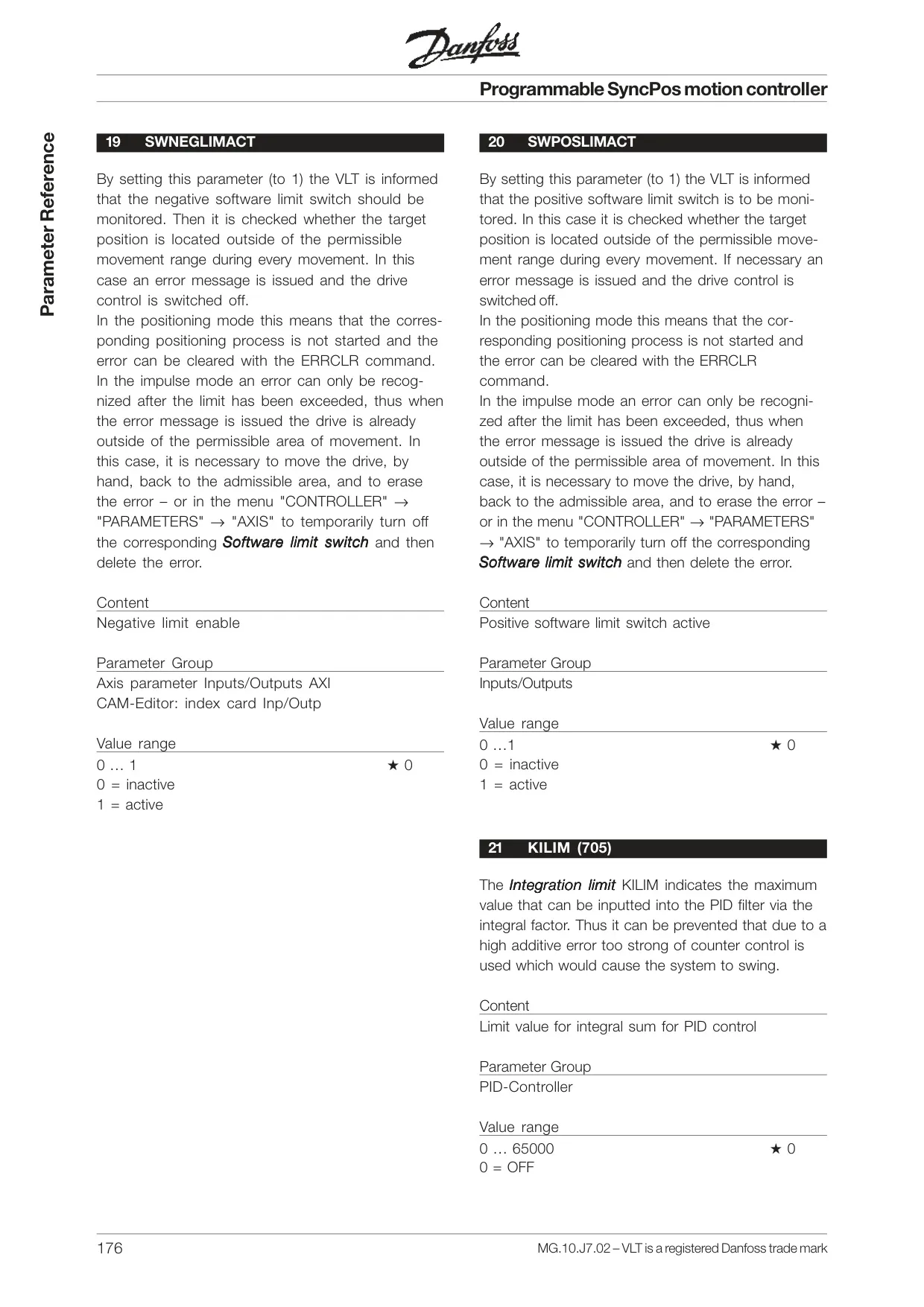
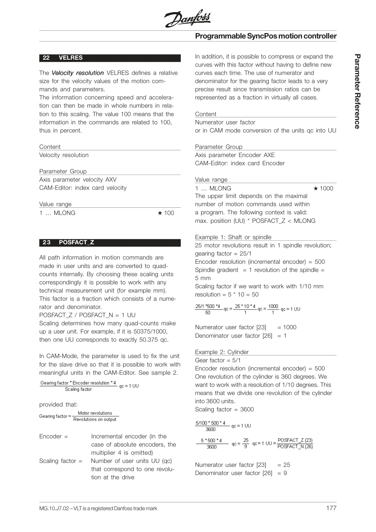
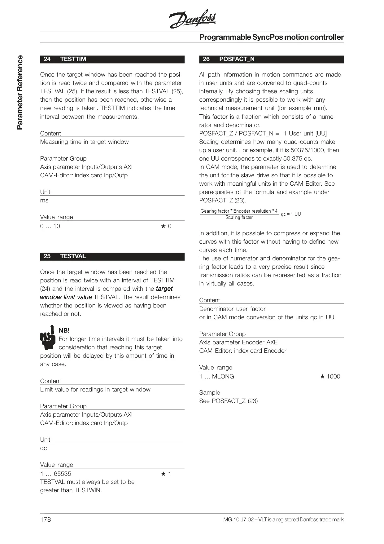
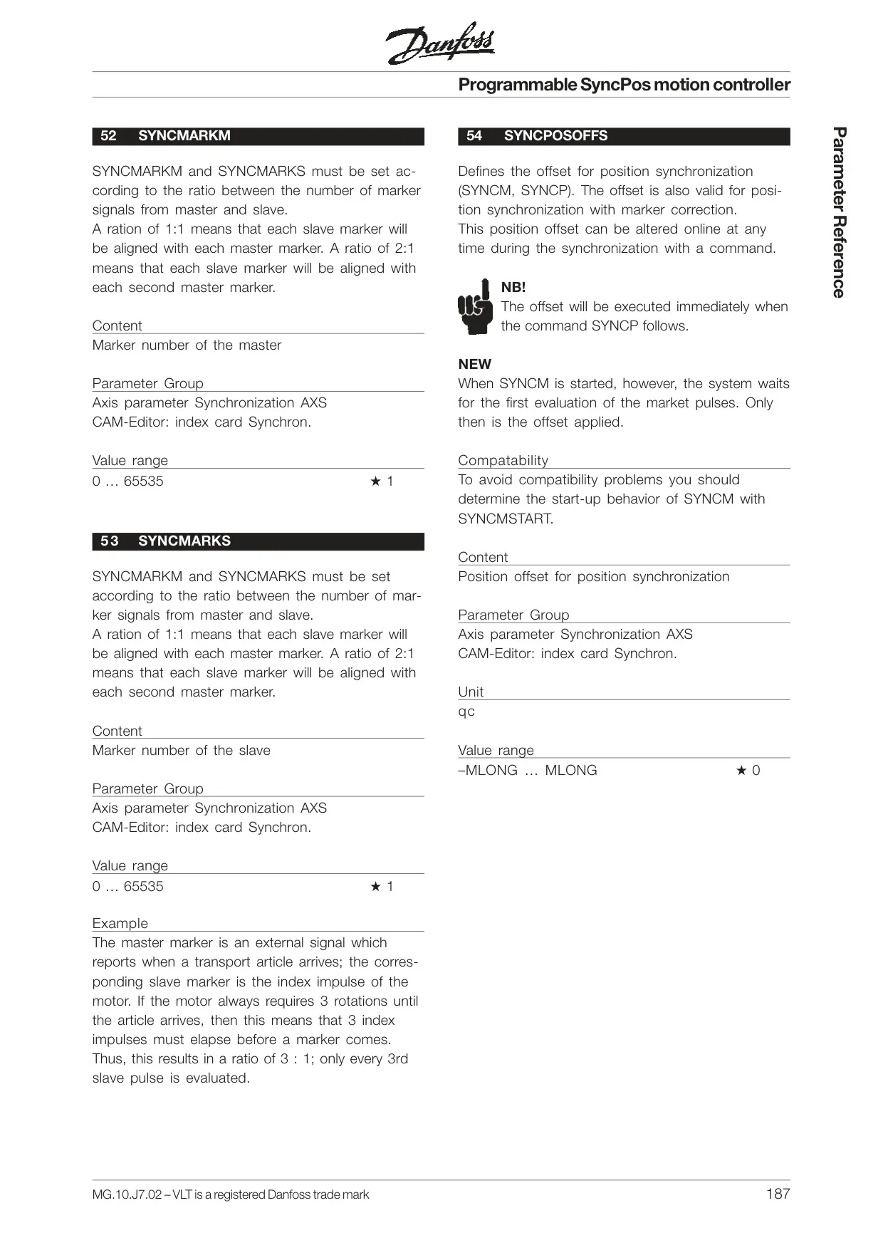
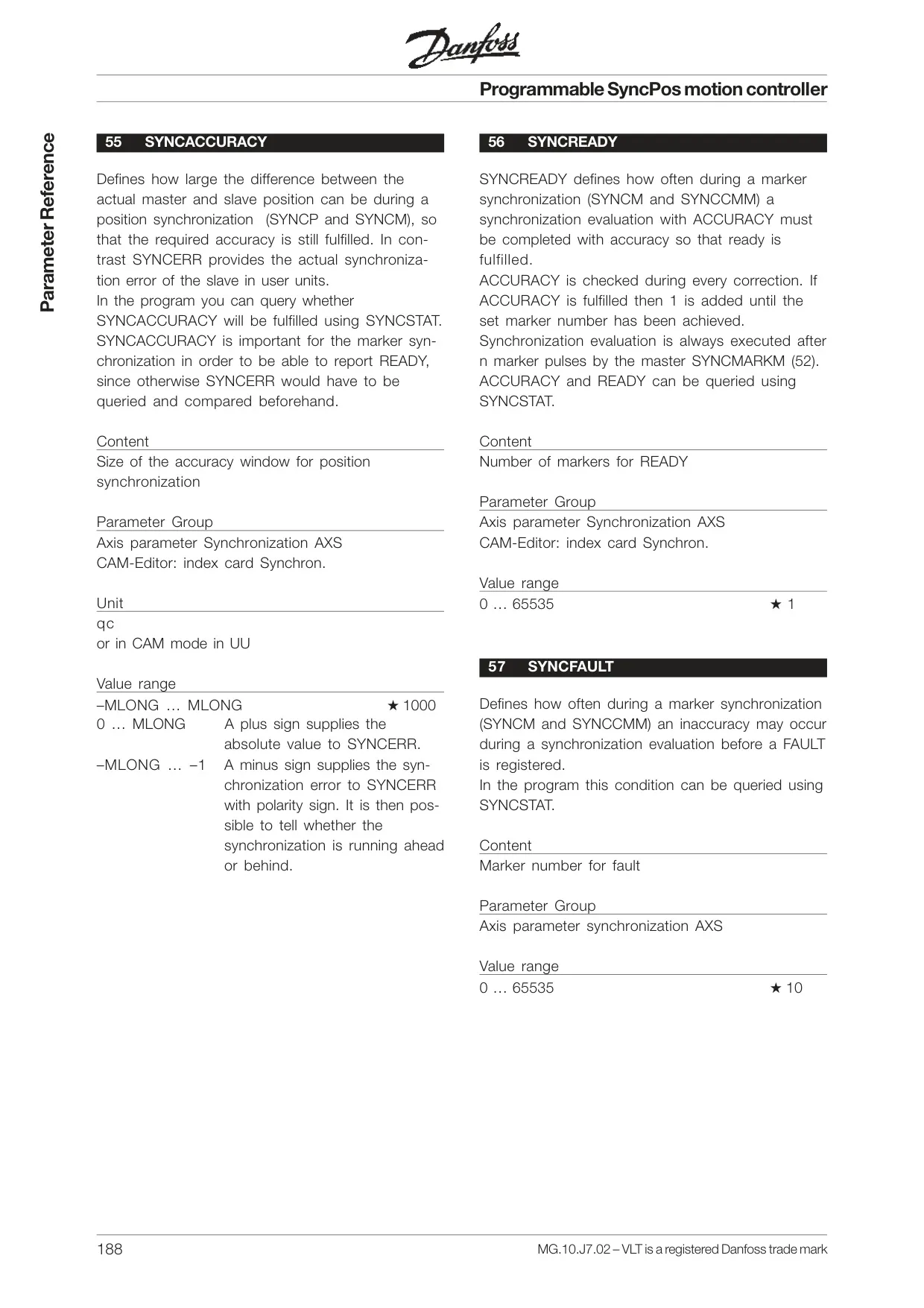
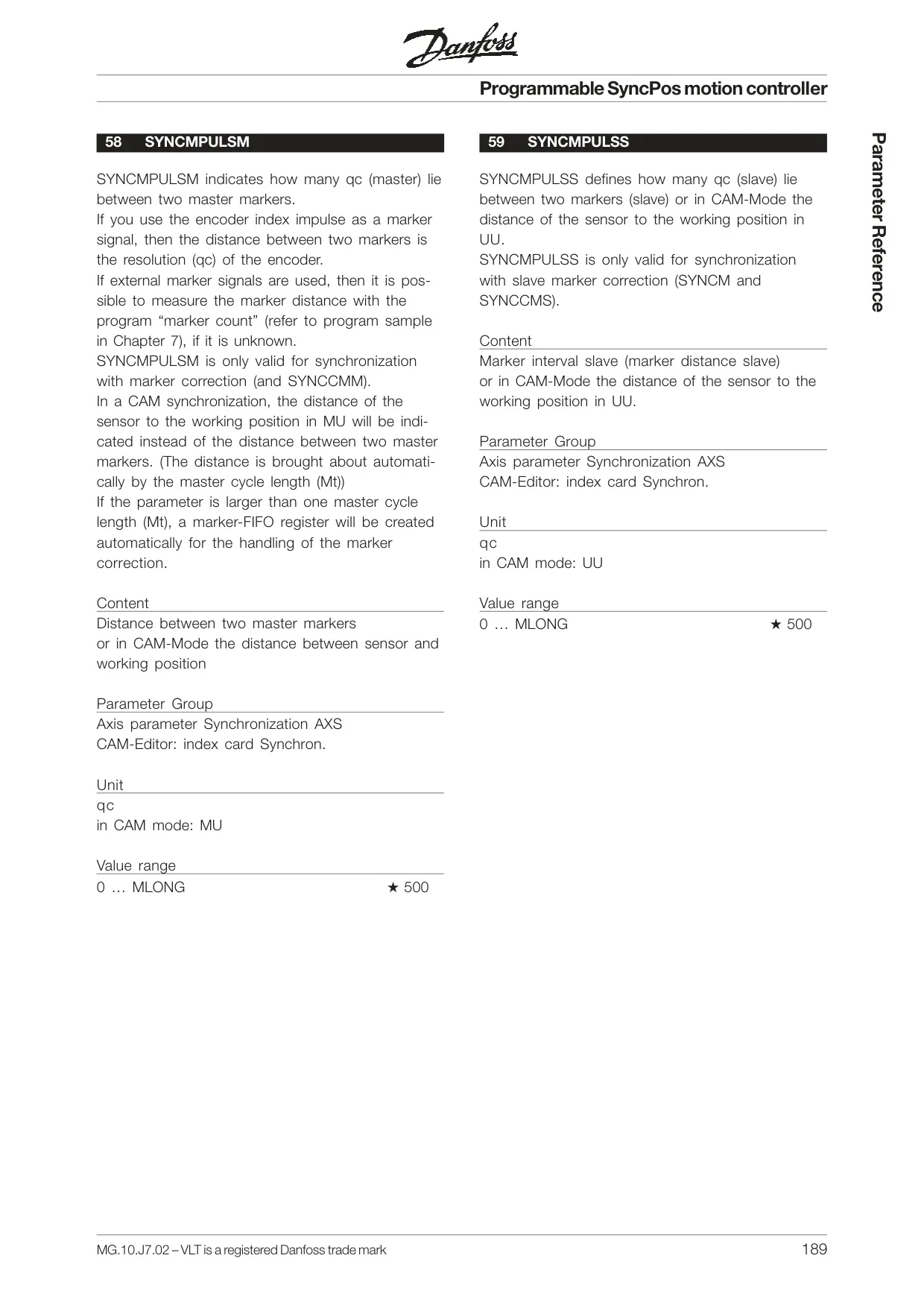
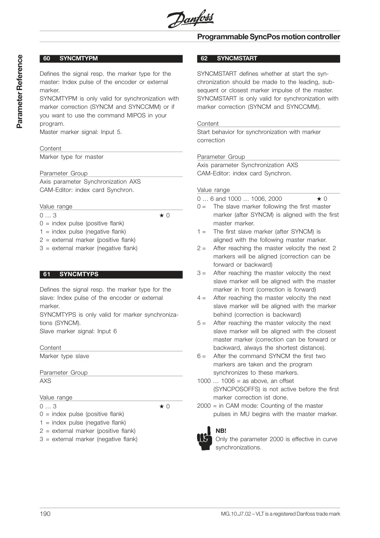
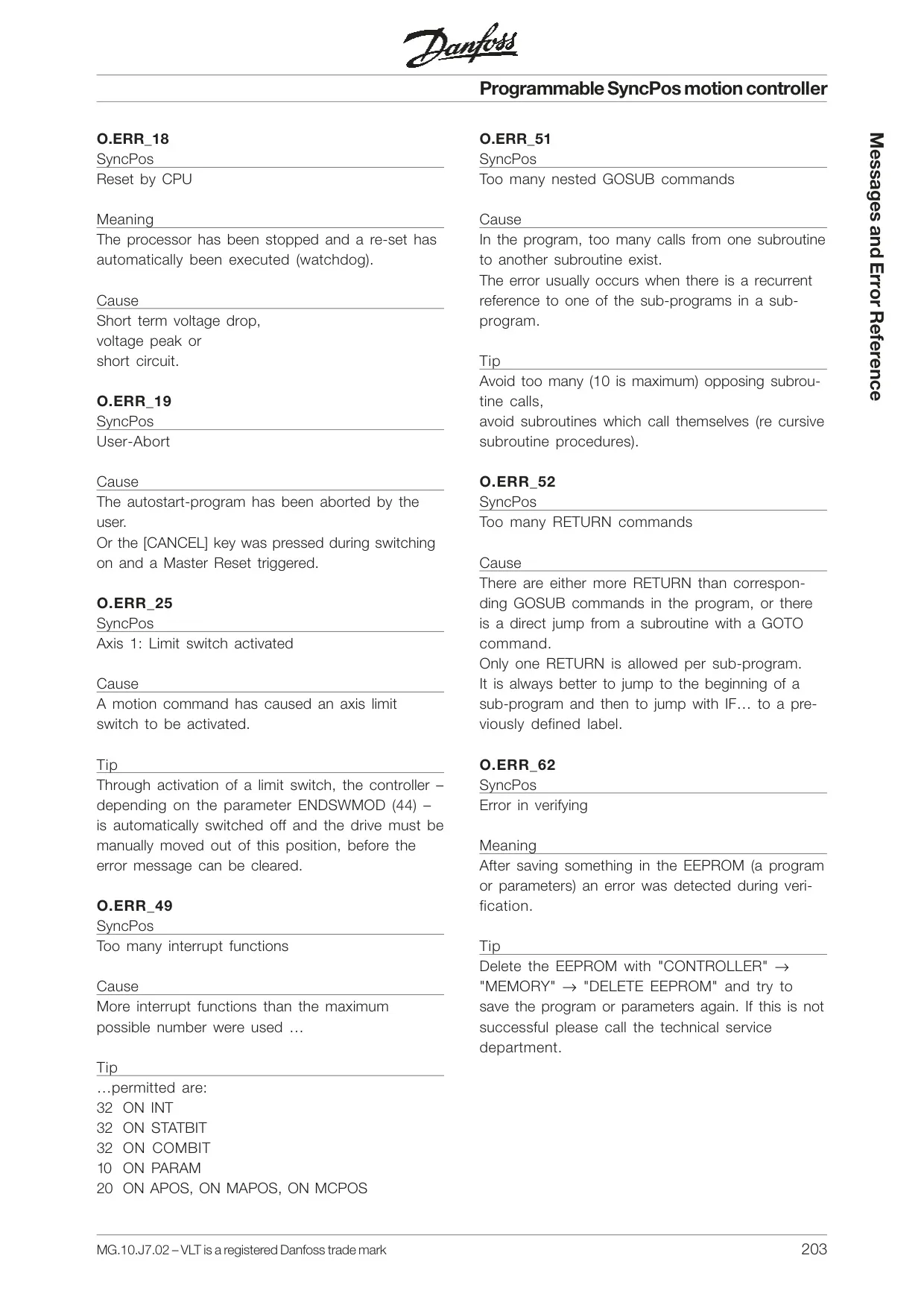
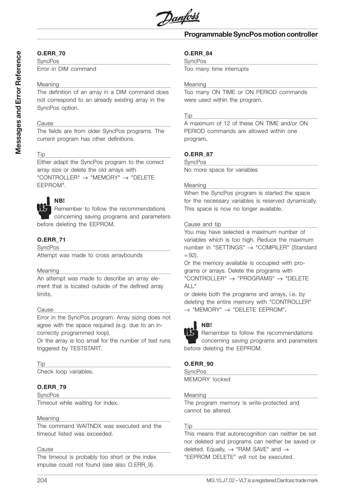
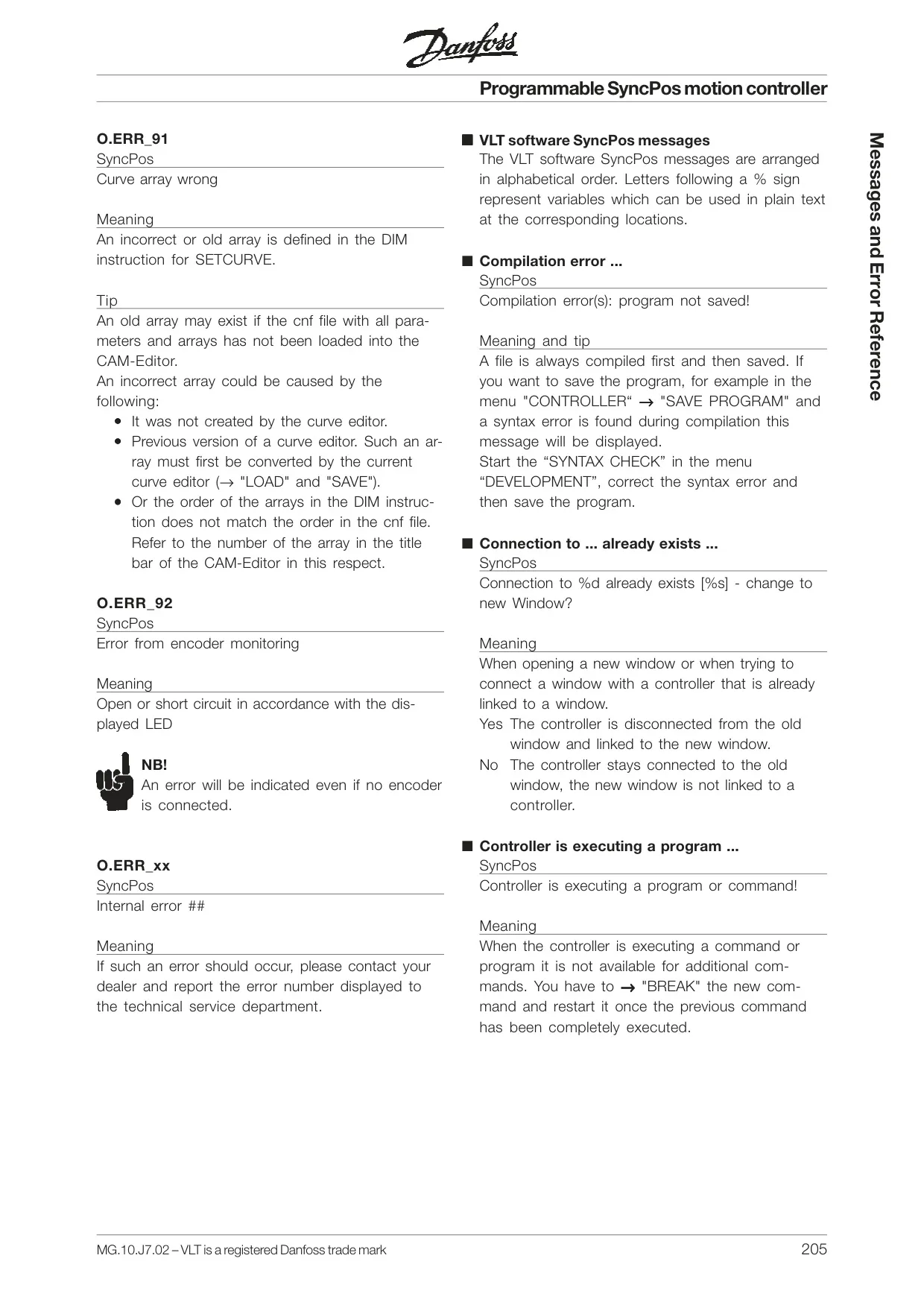
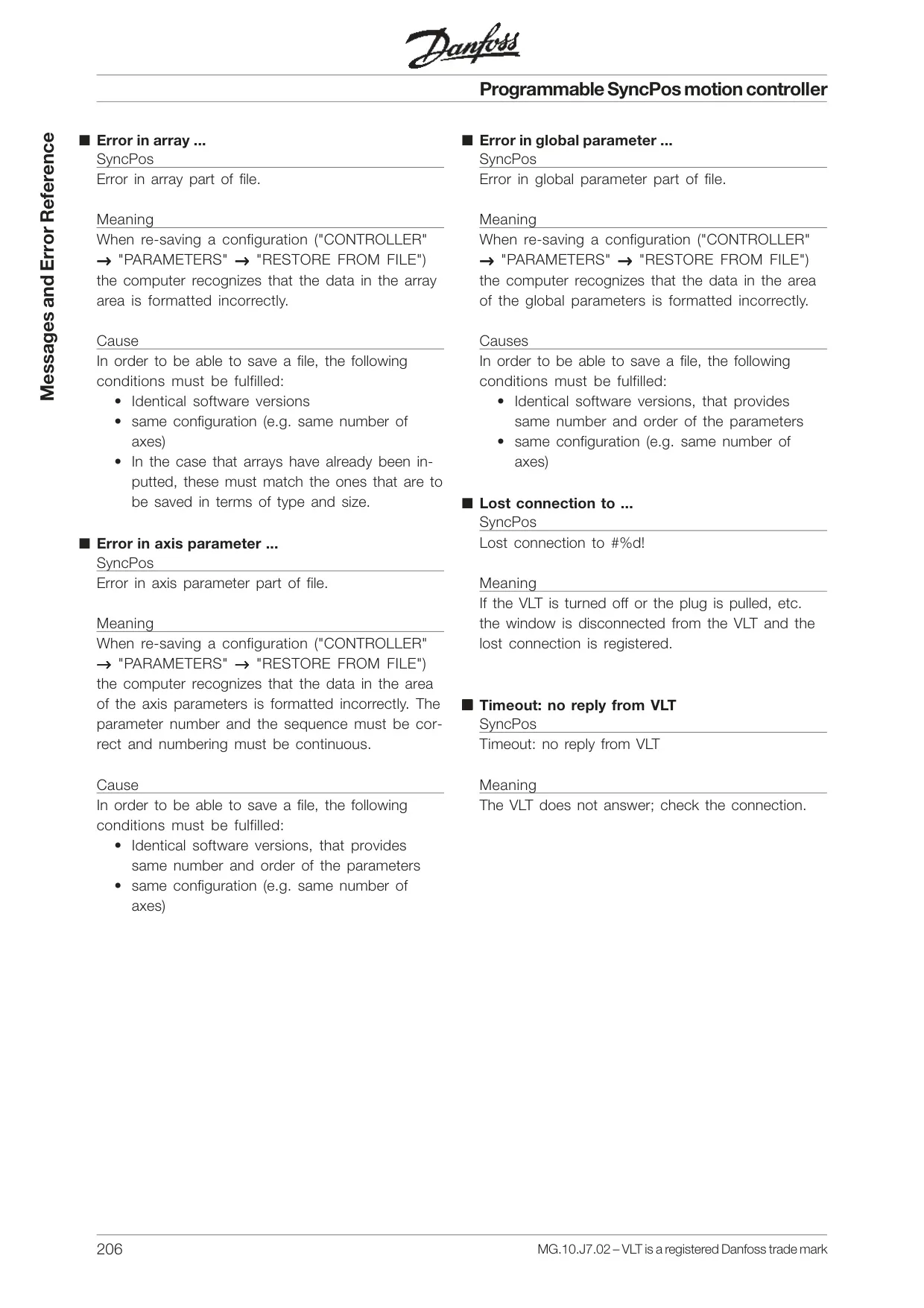
Danfoss VLT 5000 Variable Frequency Drive
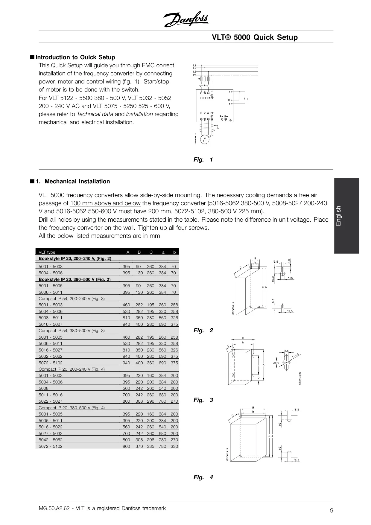
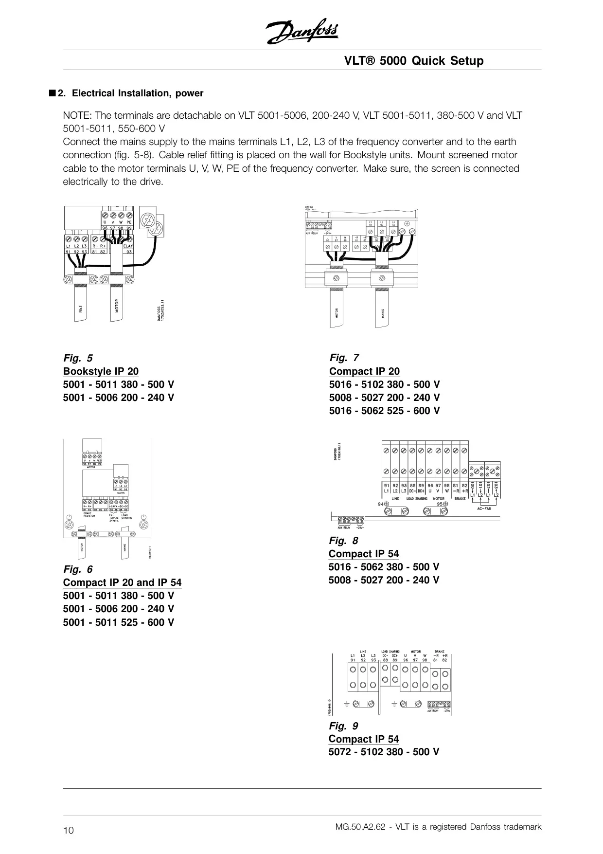
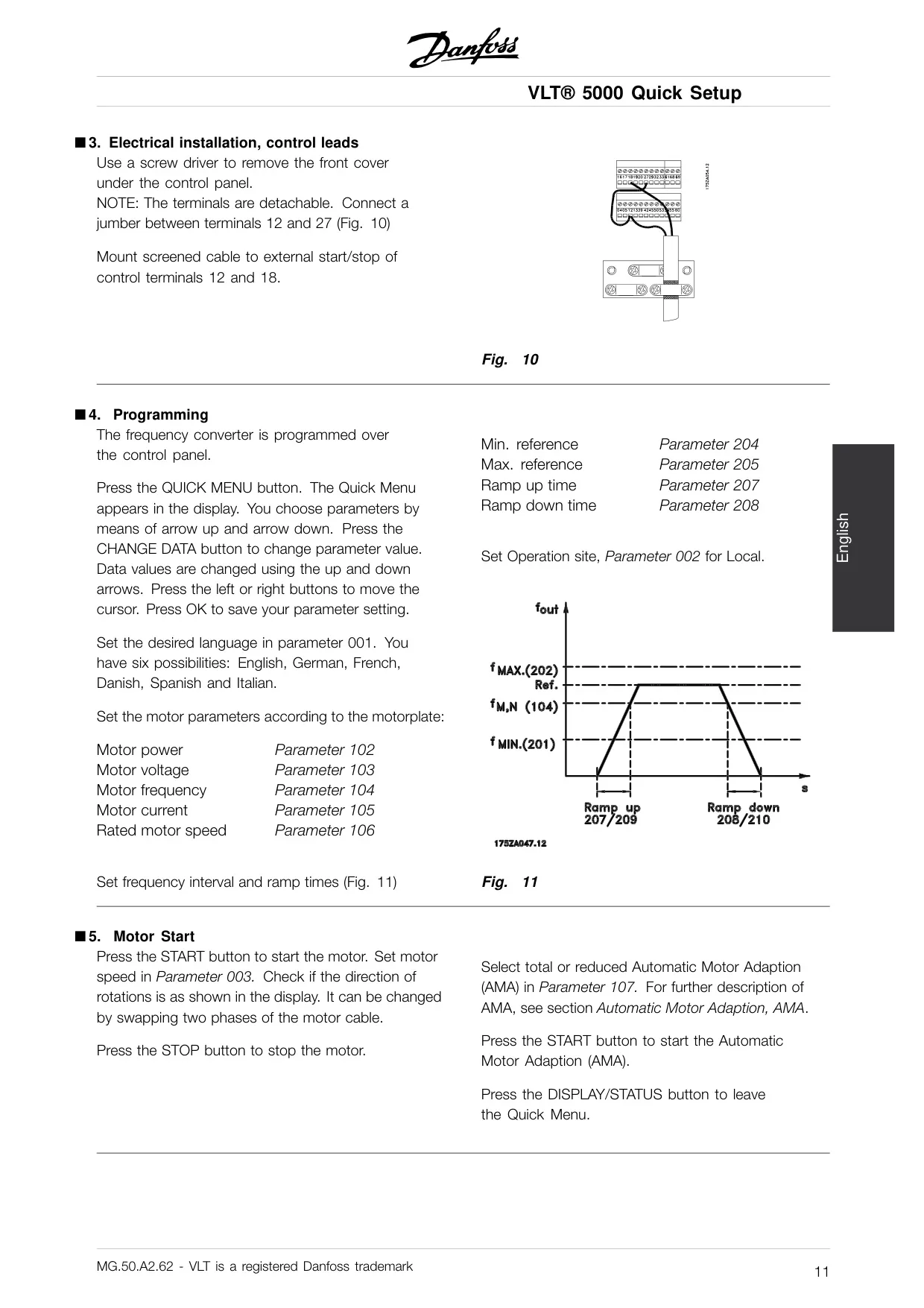
Danfoss VLT 5000 VFD Instructions
Here we offer the Danfoss VLT 5000 Variable Frequency Drive manual completely free and in English. We have cataloged this manual in the Variable Frequency Drives section on Manualverse, and it has been rated by 1 users with an average rating of 5. If you have any specific questions about Danfoss VLT 5000 Variable Frequency Drive, we suggest checking the Frequently Asked Questions (FAQs) section of this manual.
Product Images
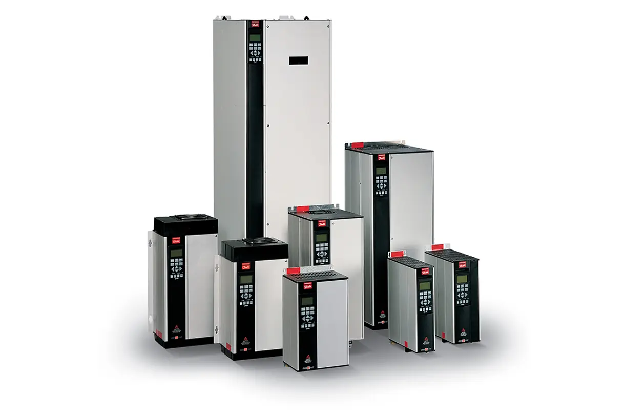
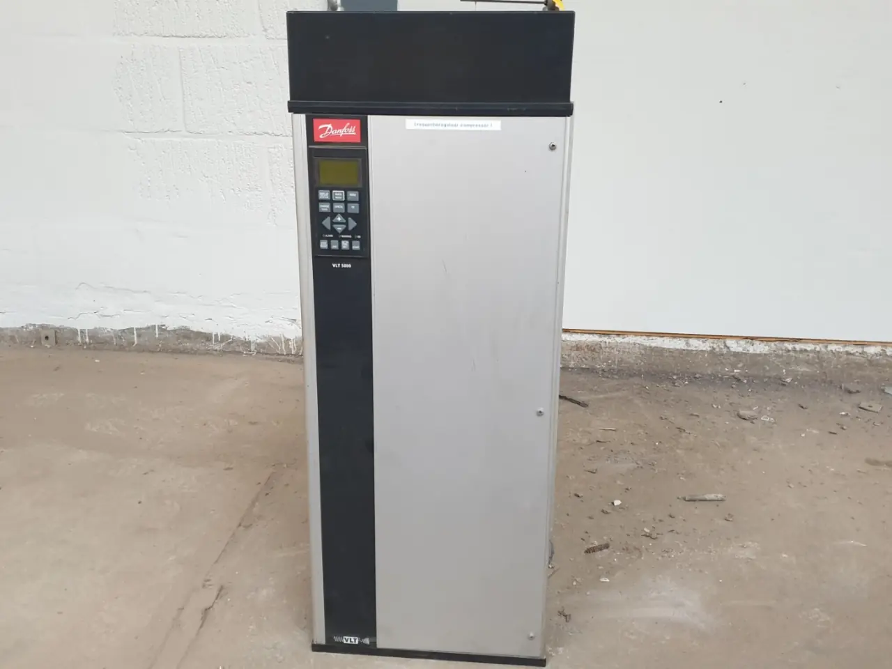
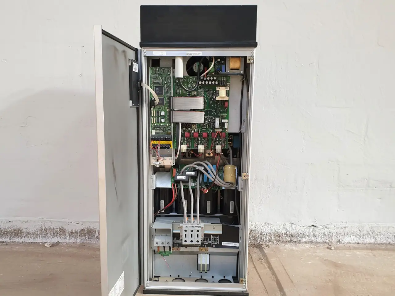
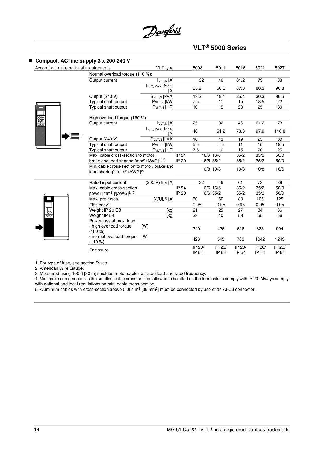
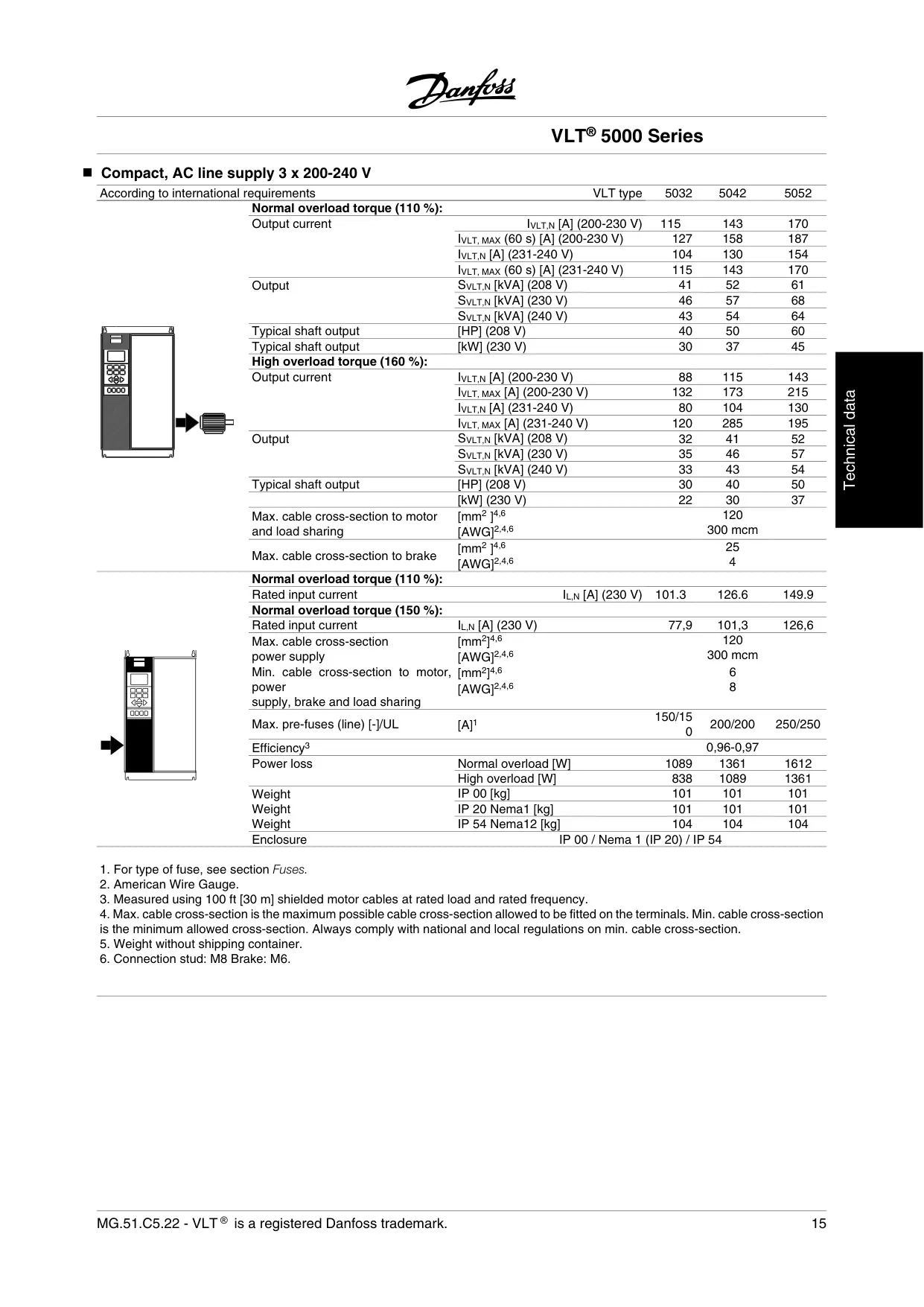
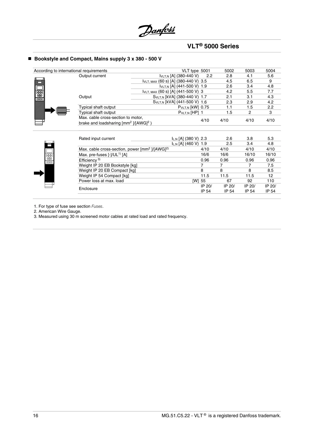
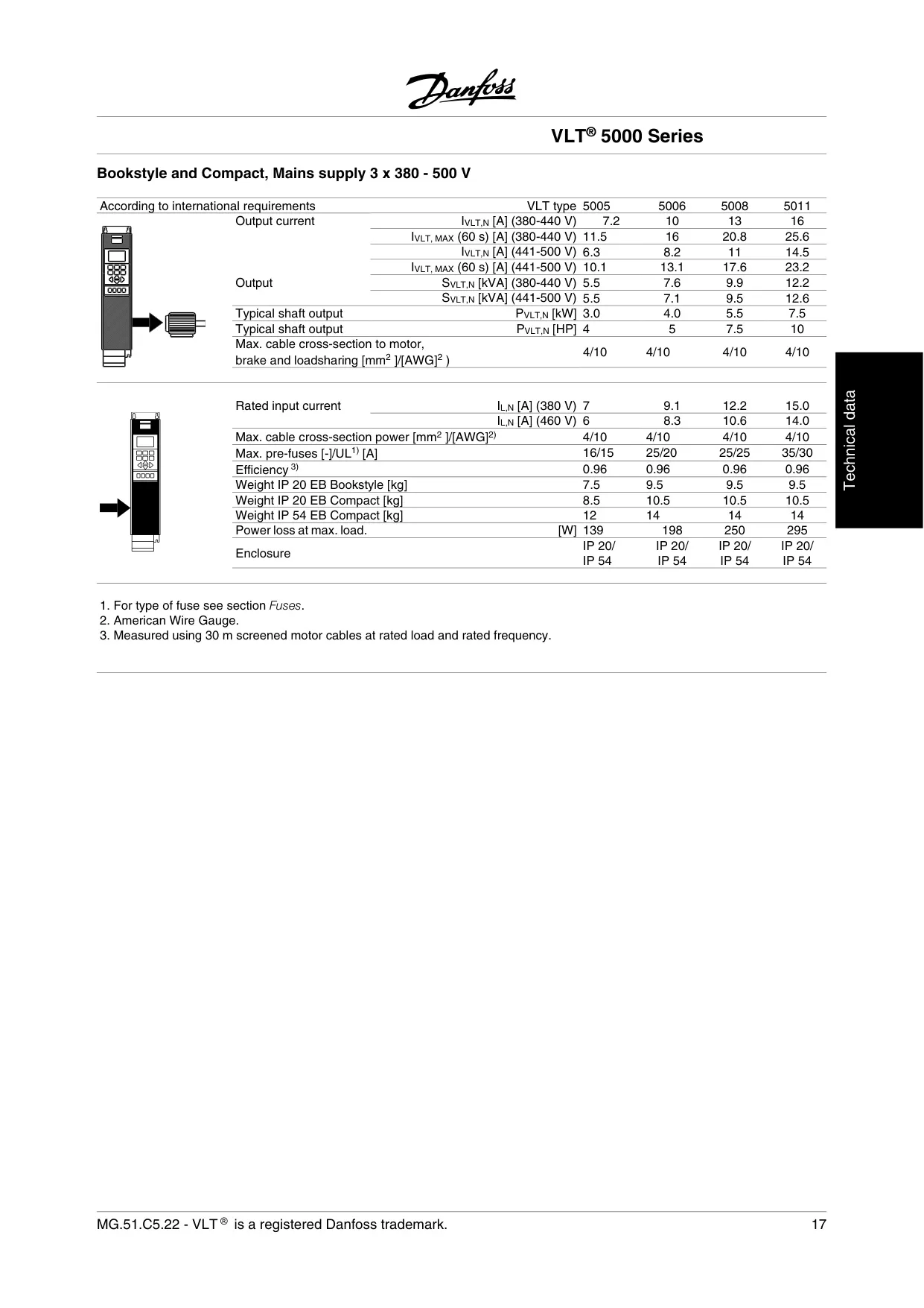
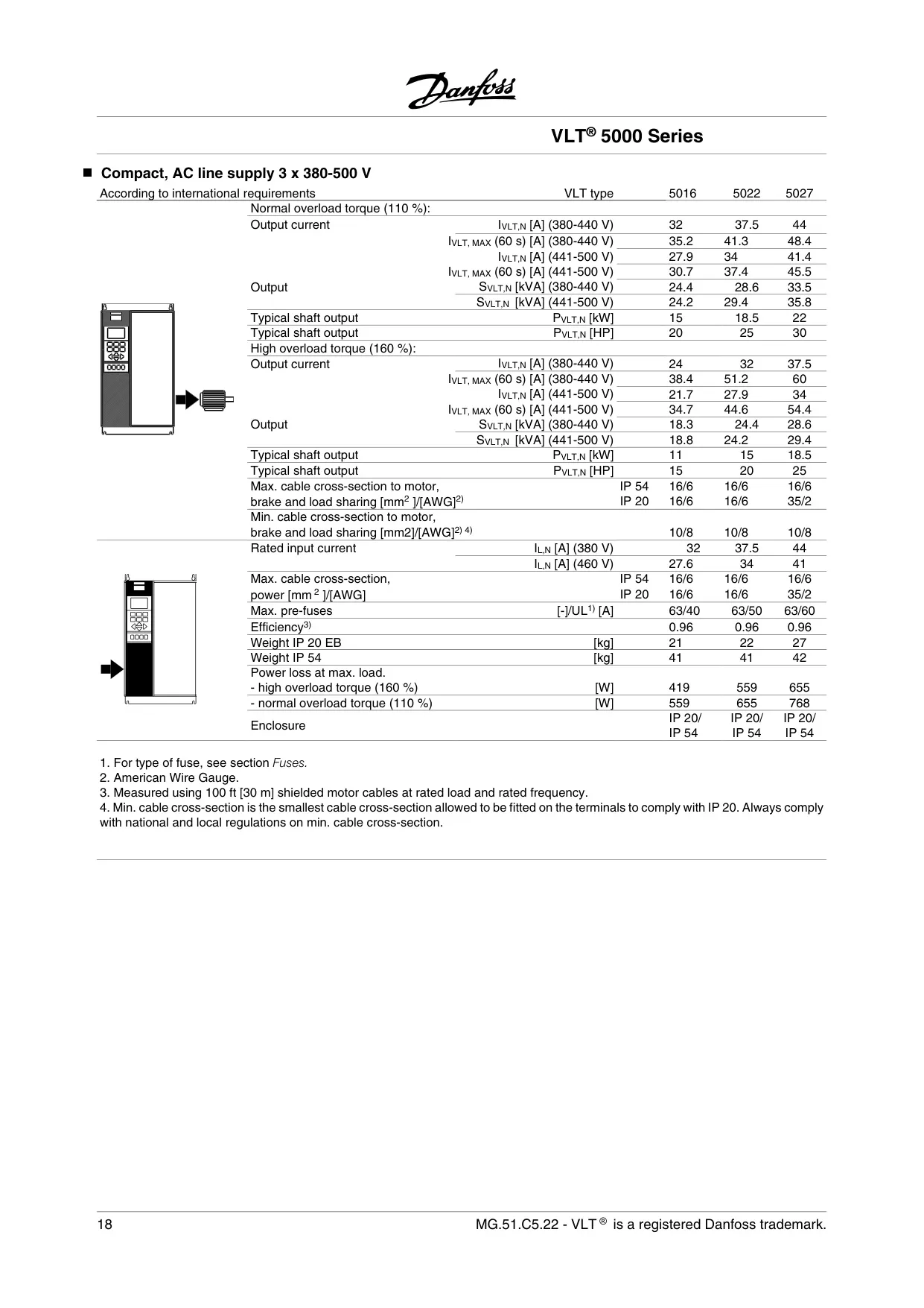
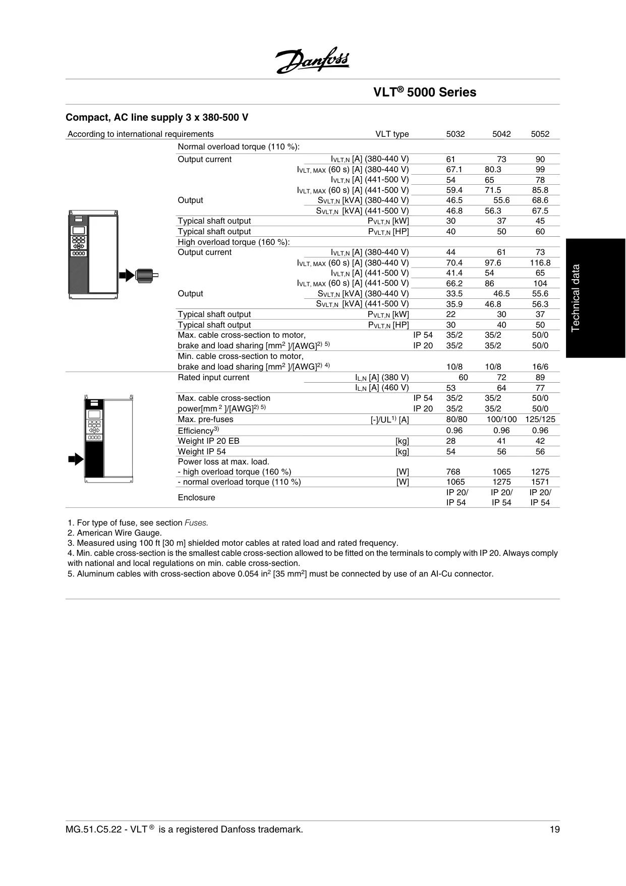
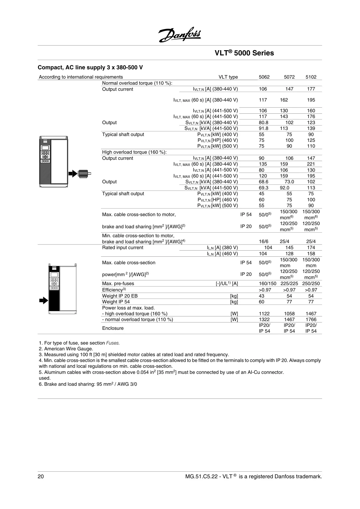
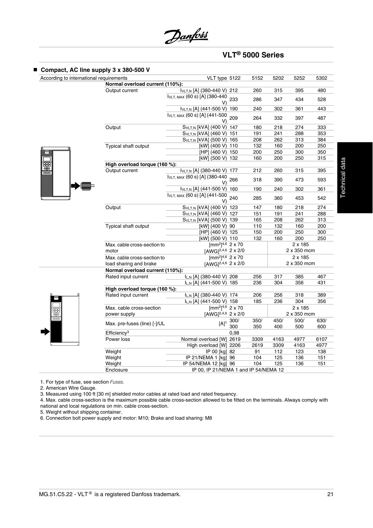
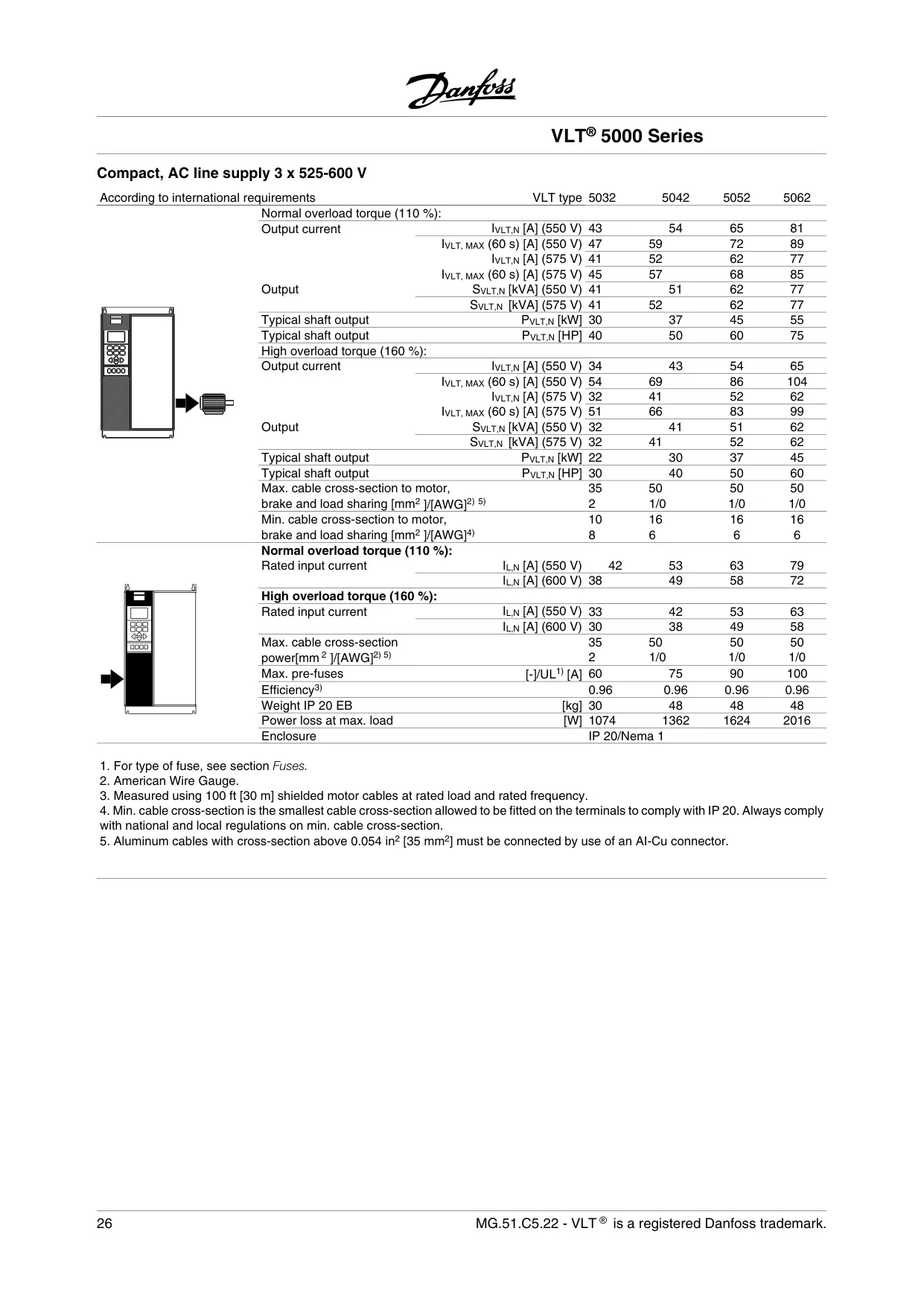
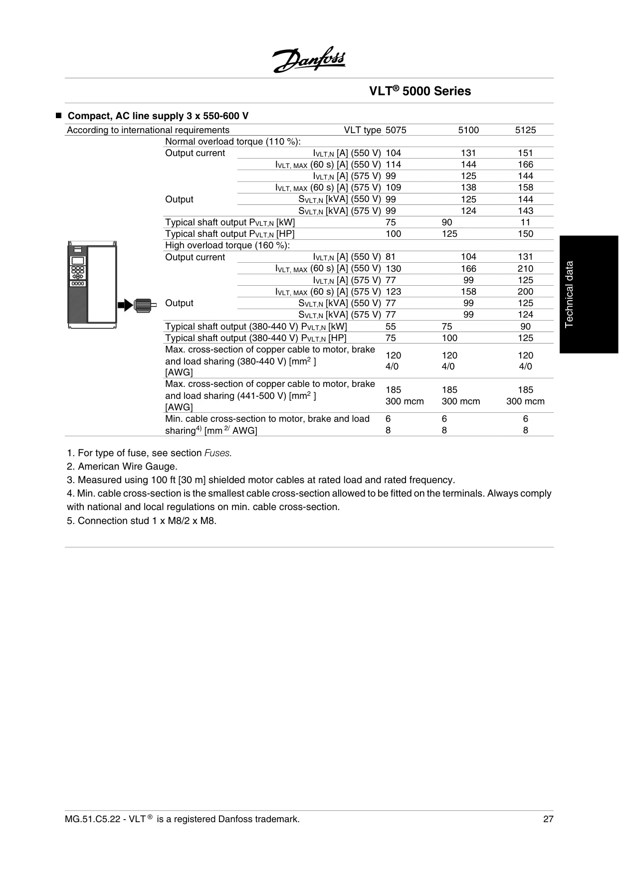
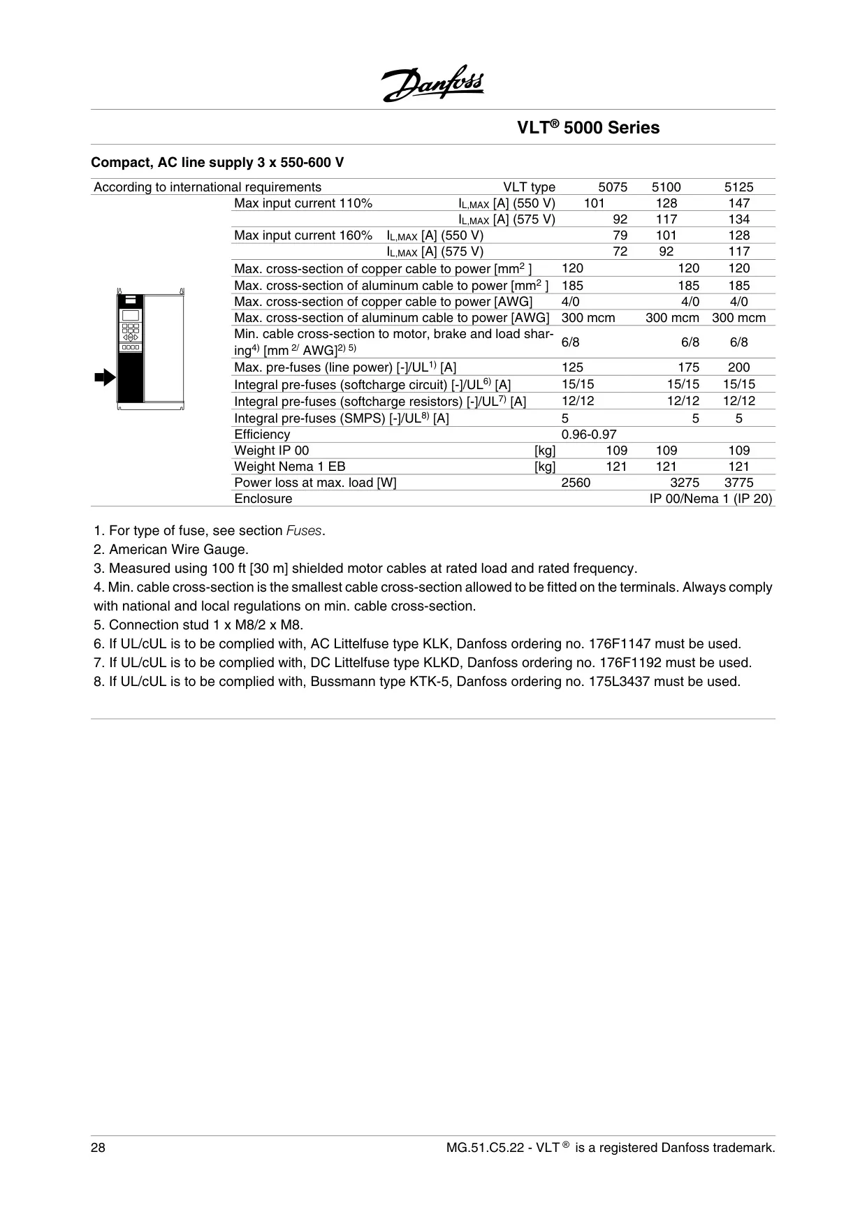
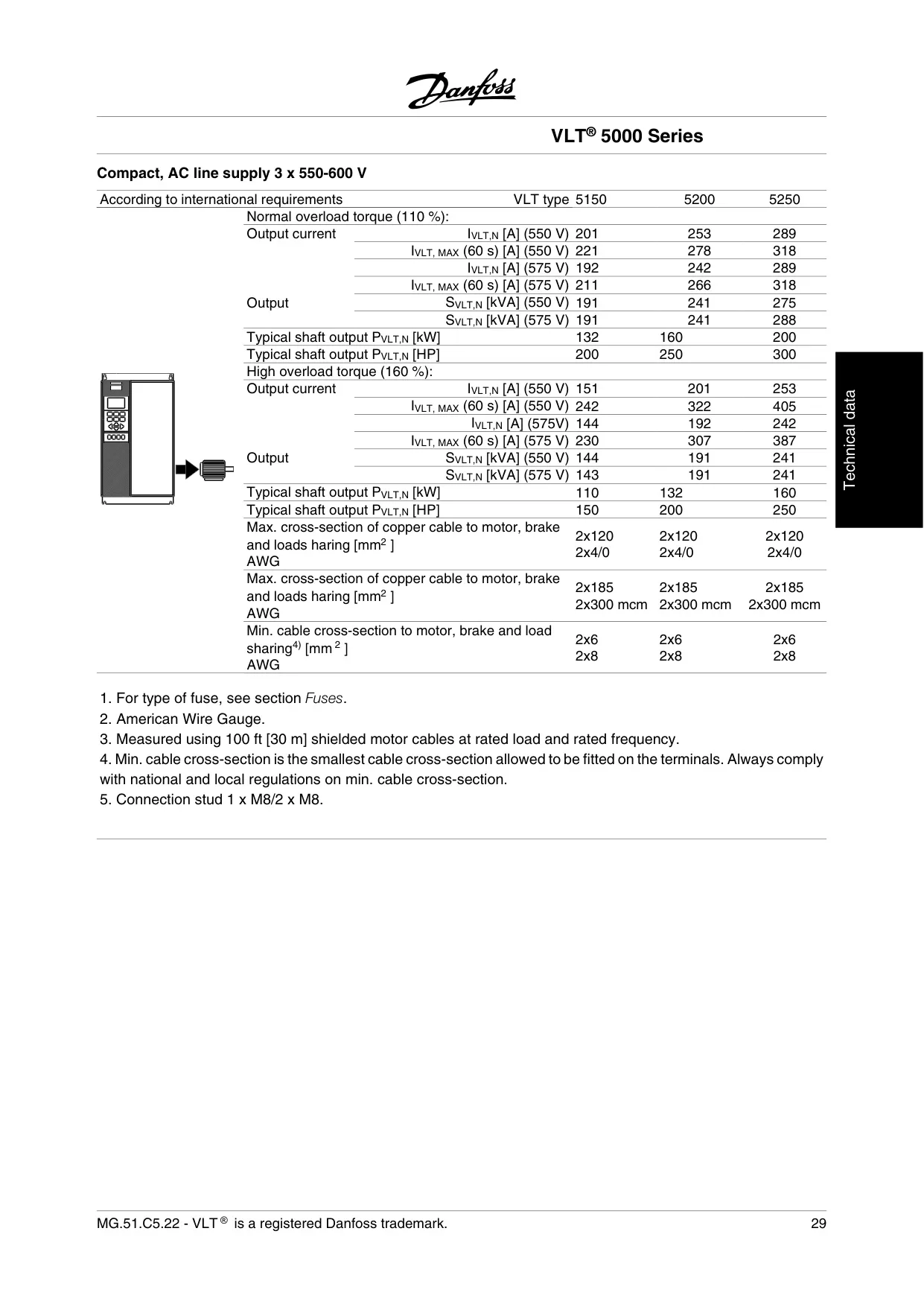
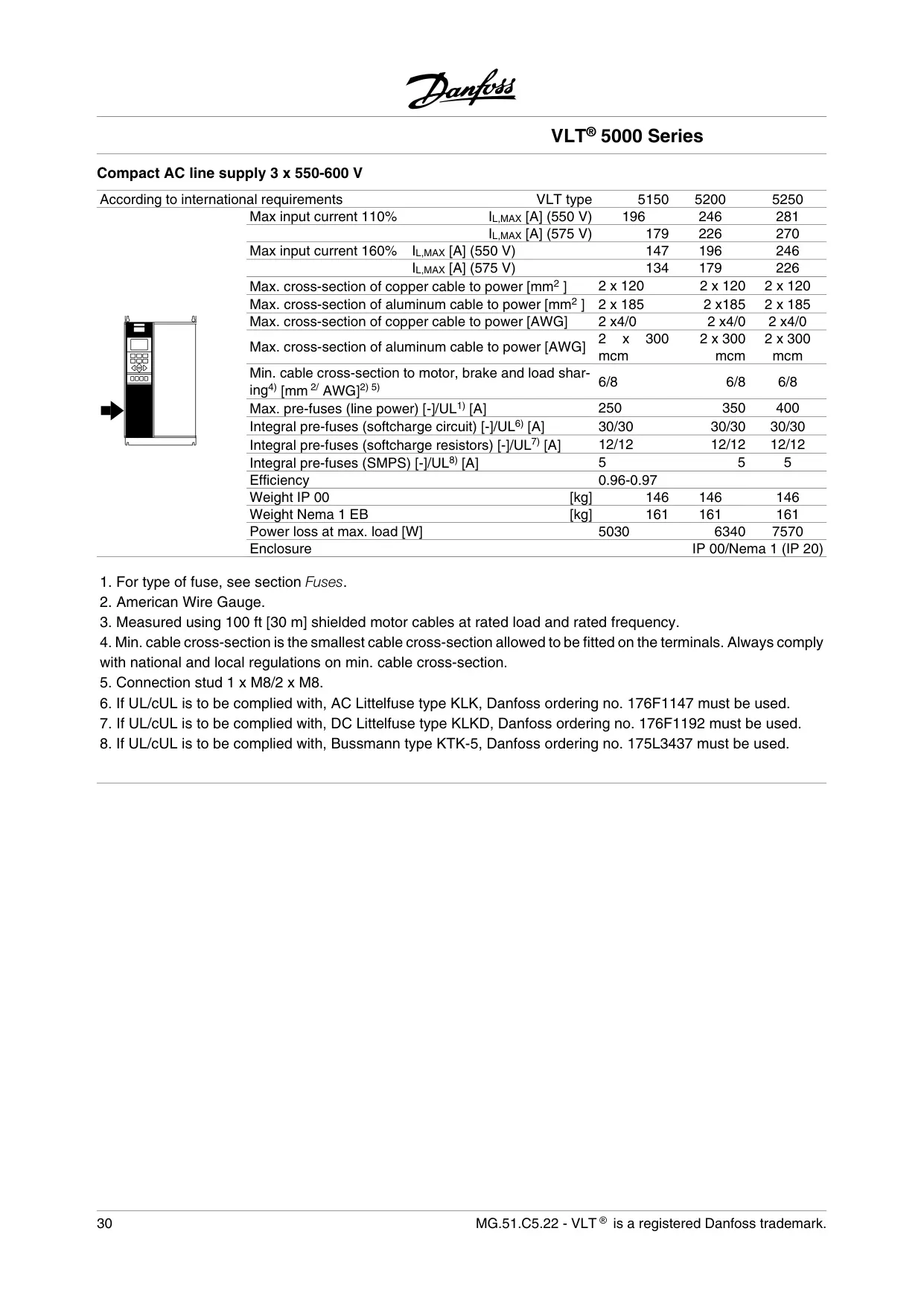
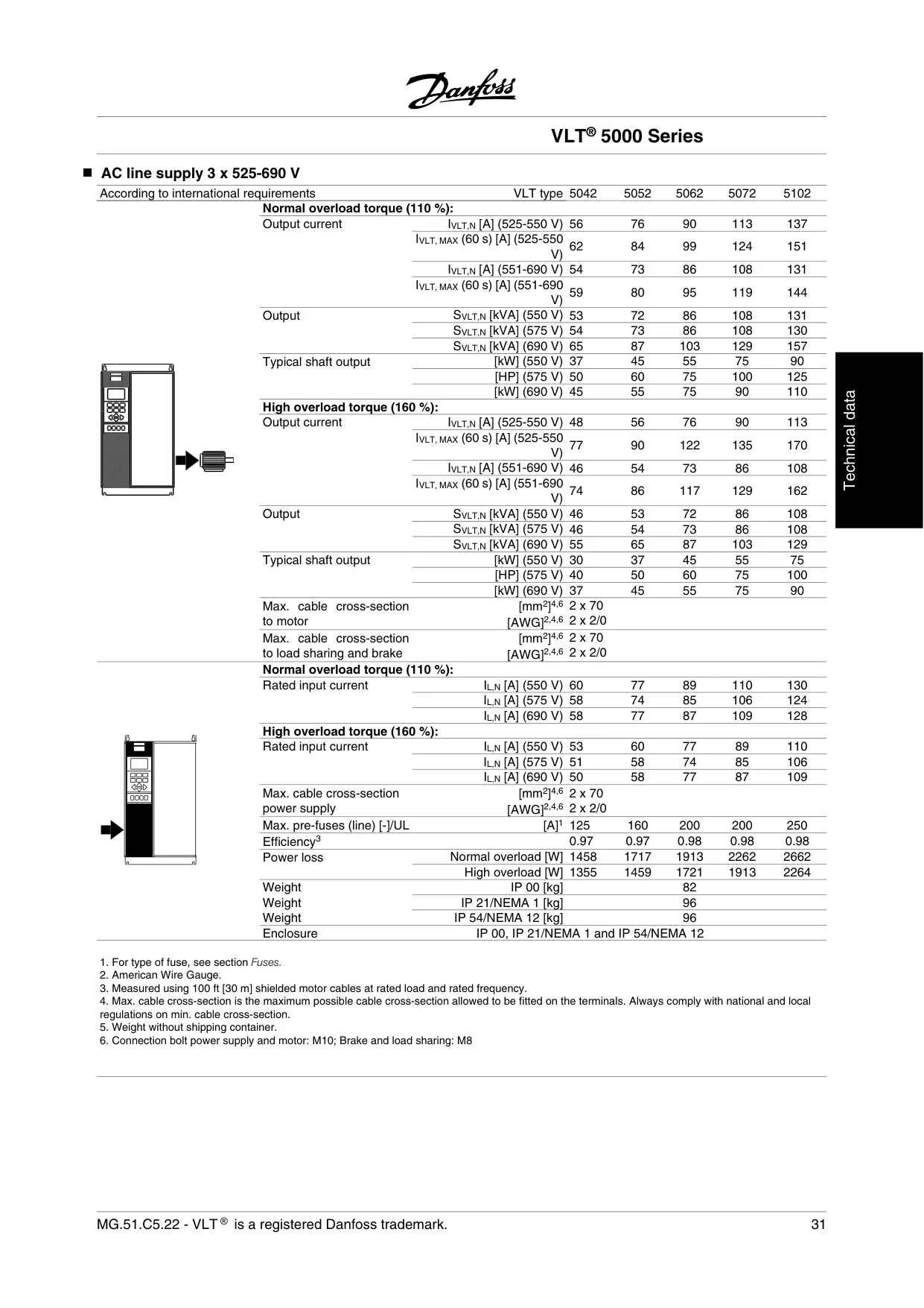
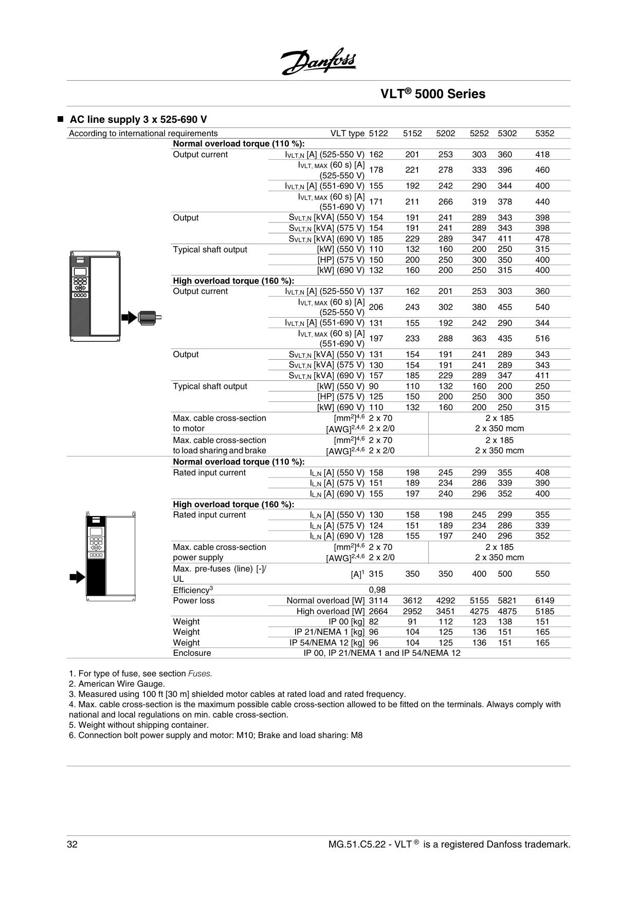
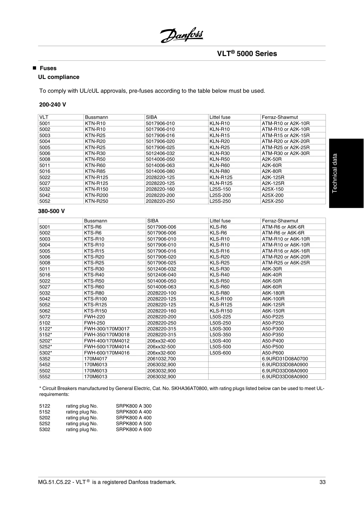
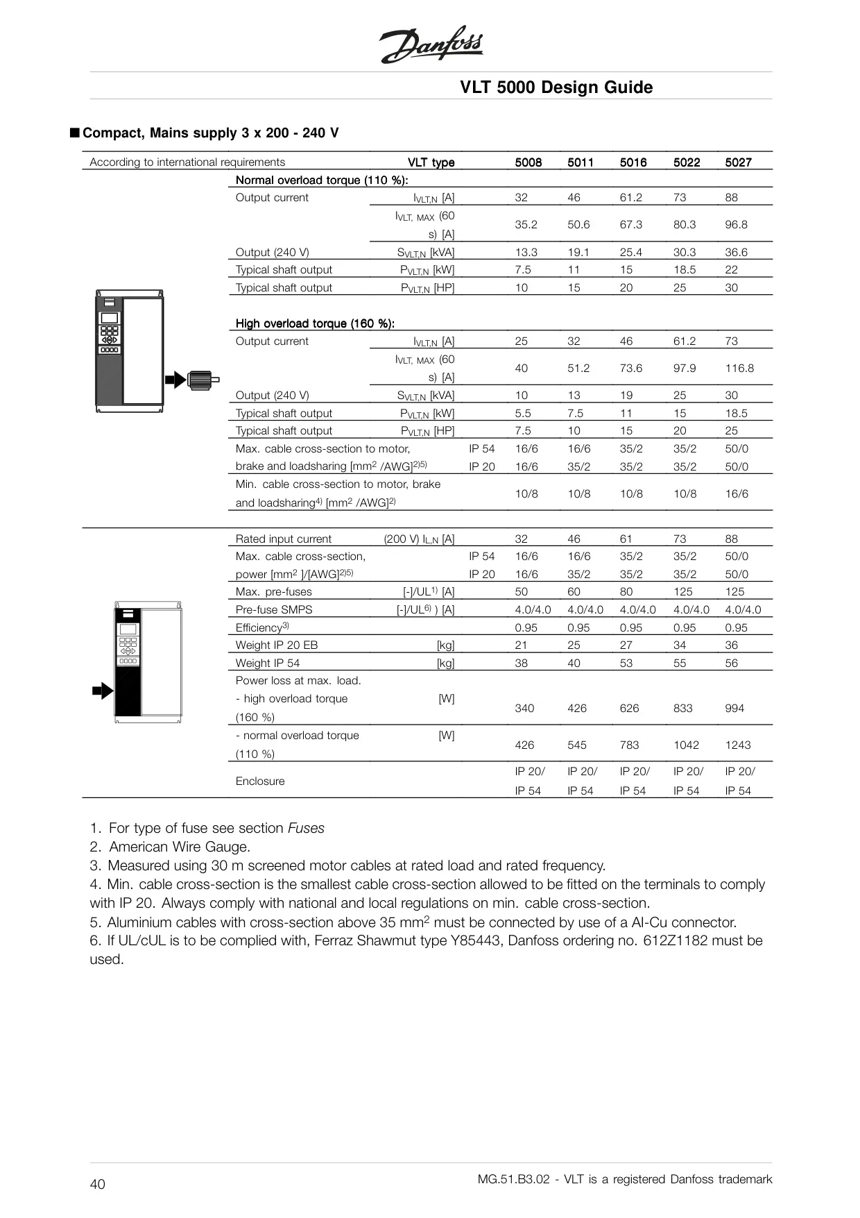
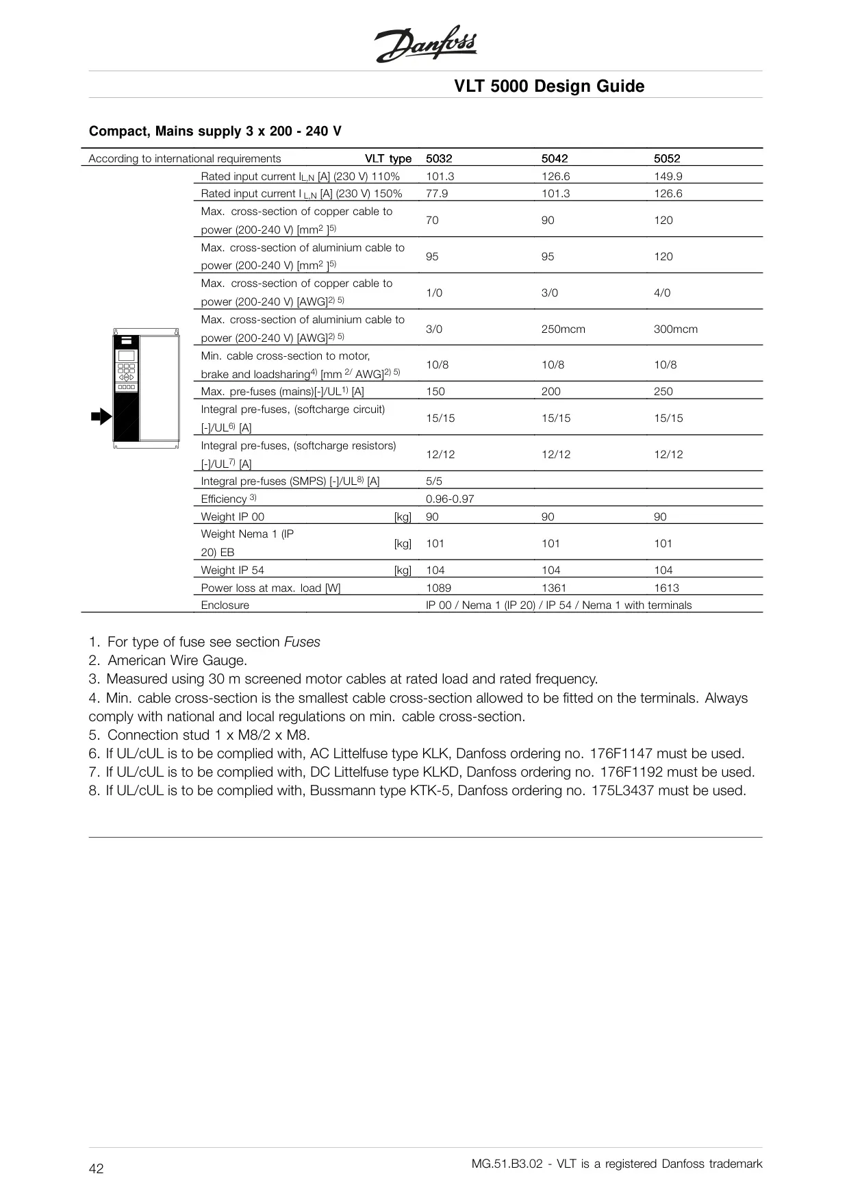
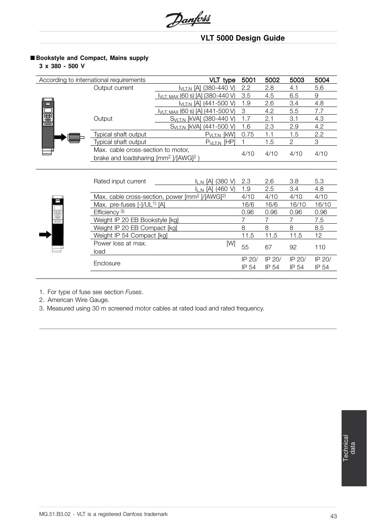
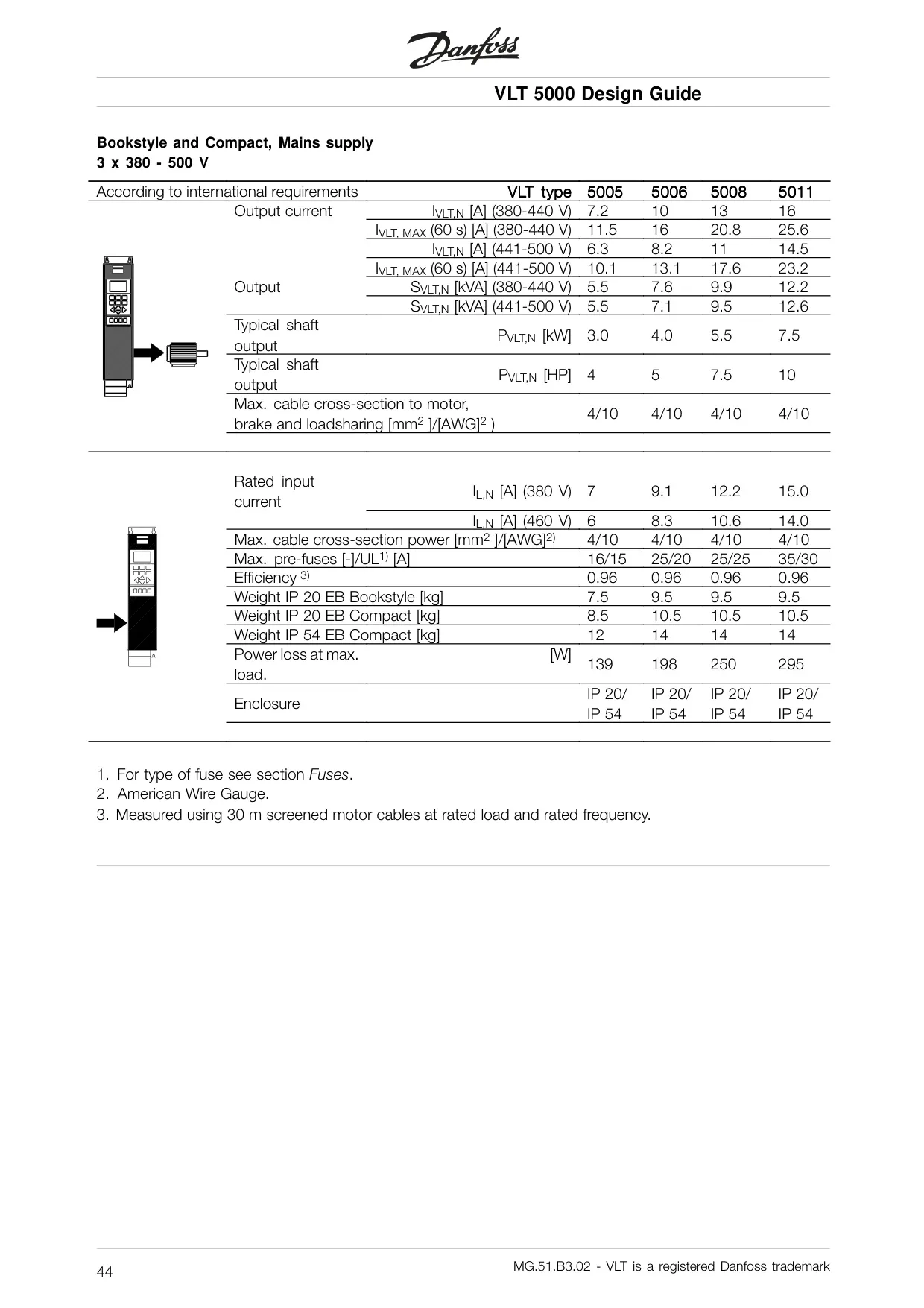
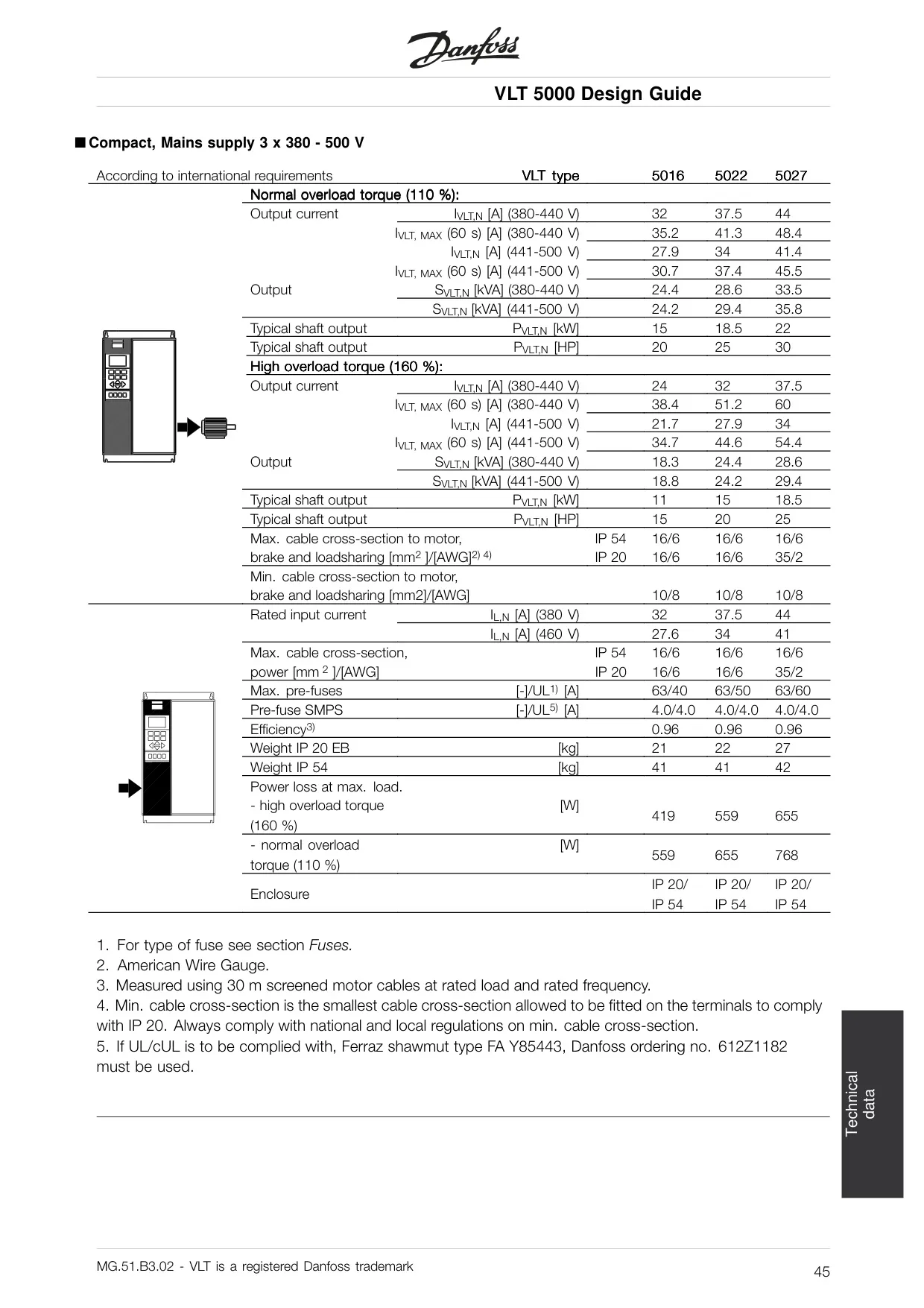
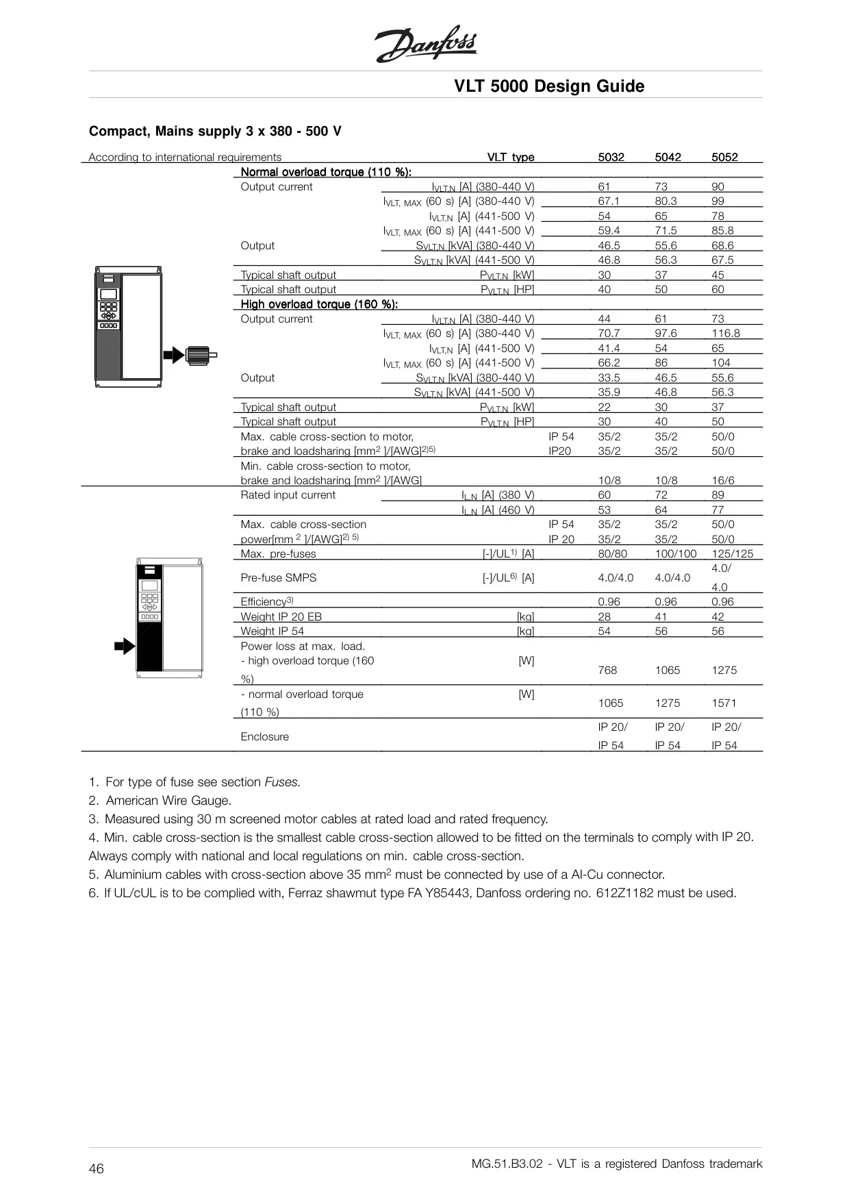
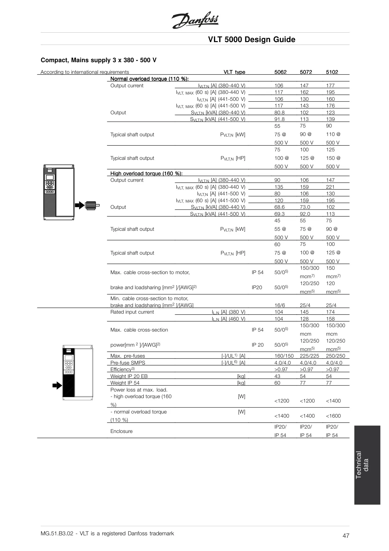
Danfoss VLT 5000 Variable Frequency Drive Specifications
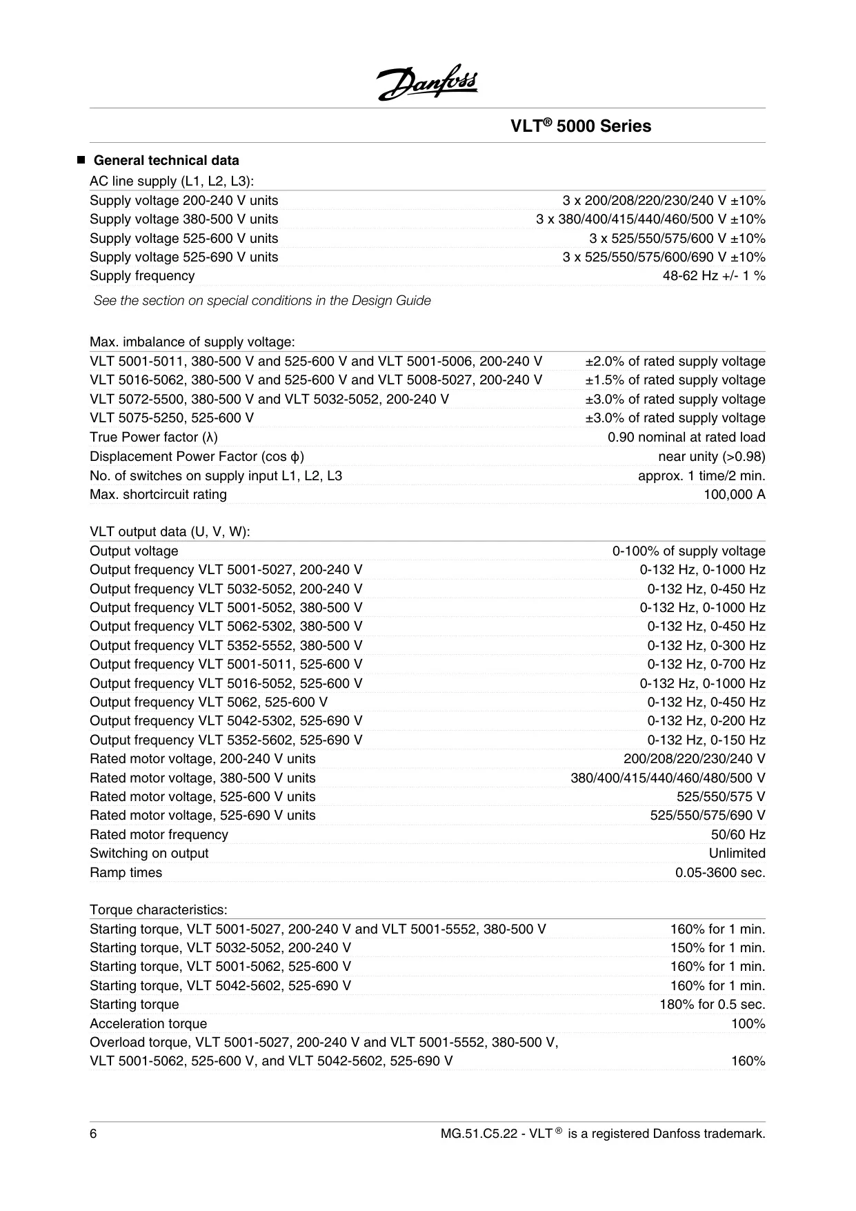
| Feature | Specification |
|---|---|
| AC Line Supply | |
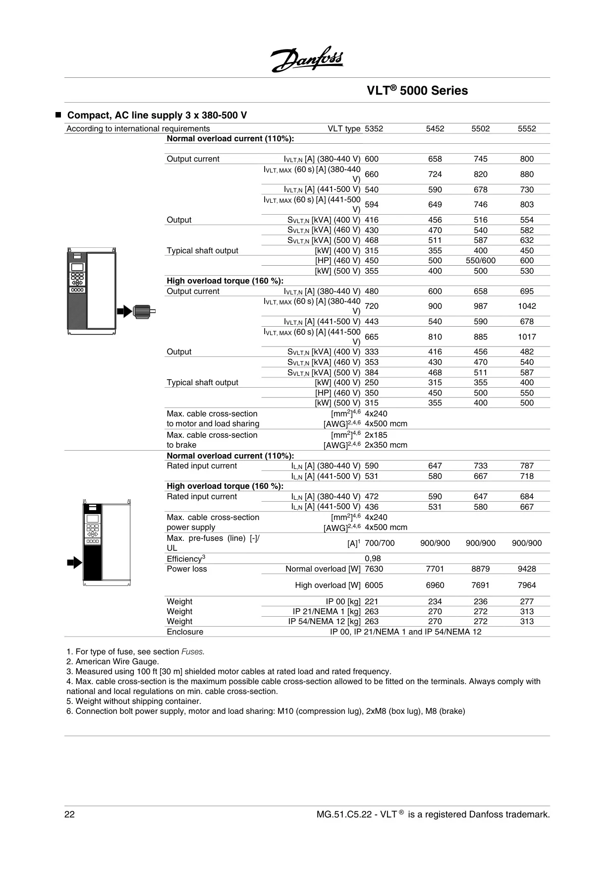
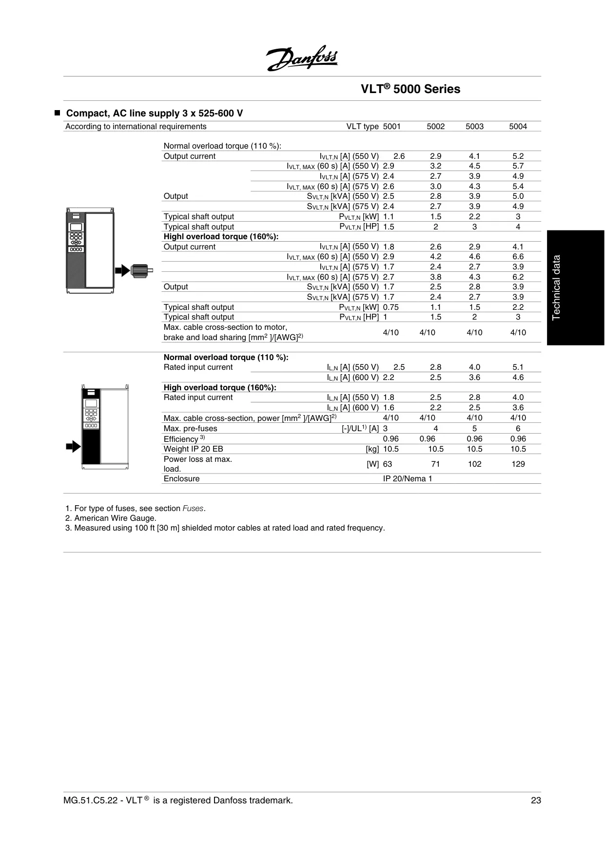
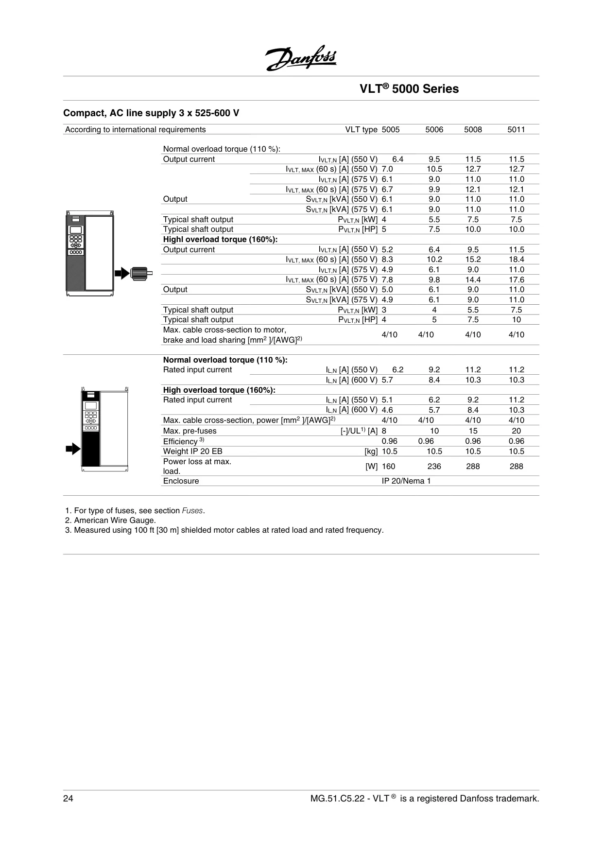
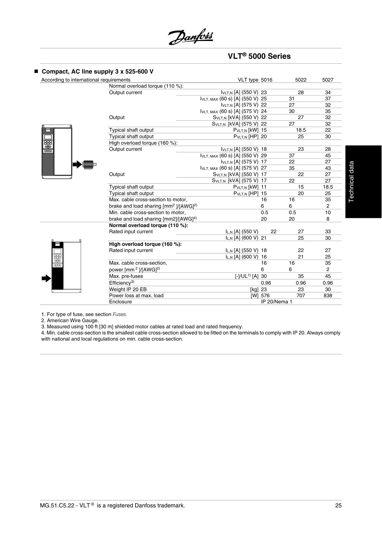
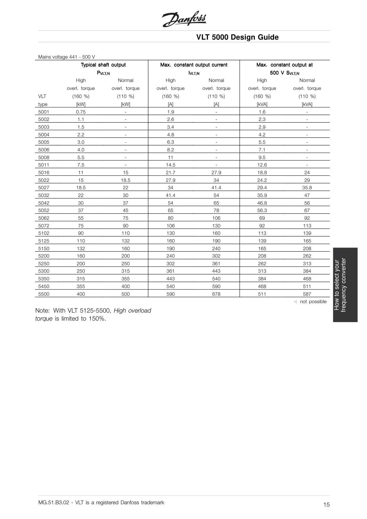
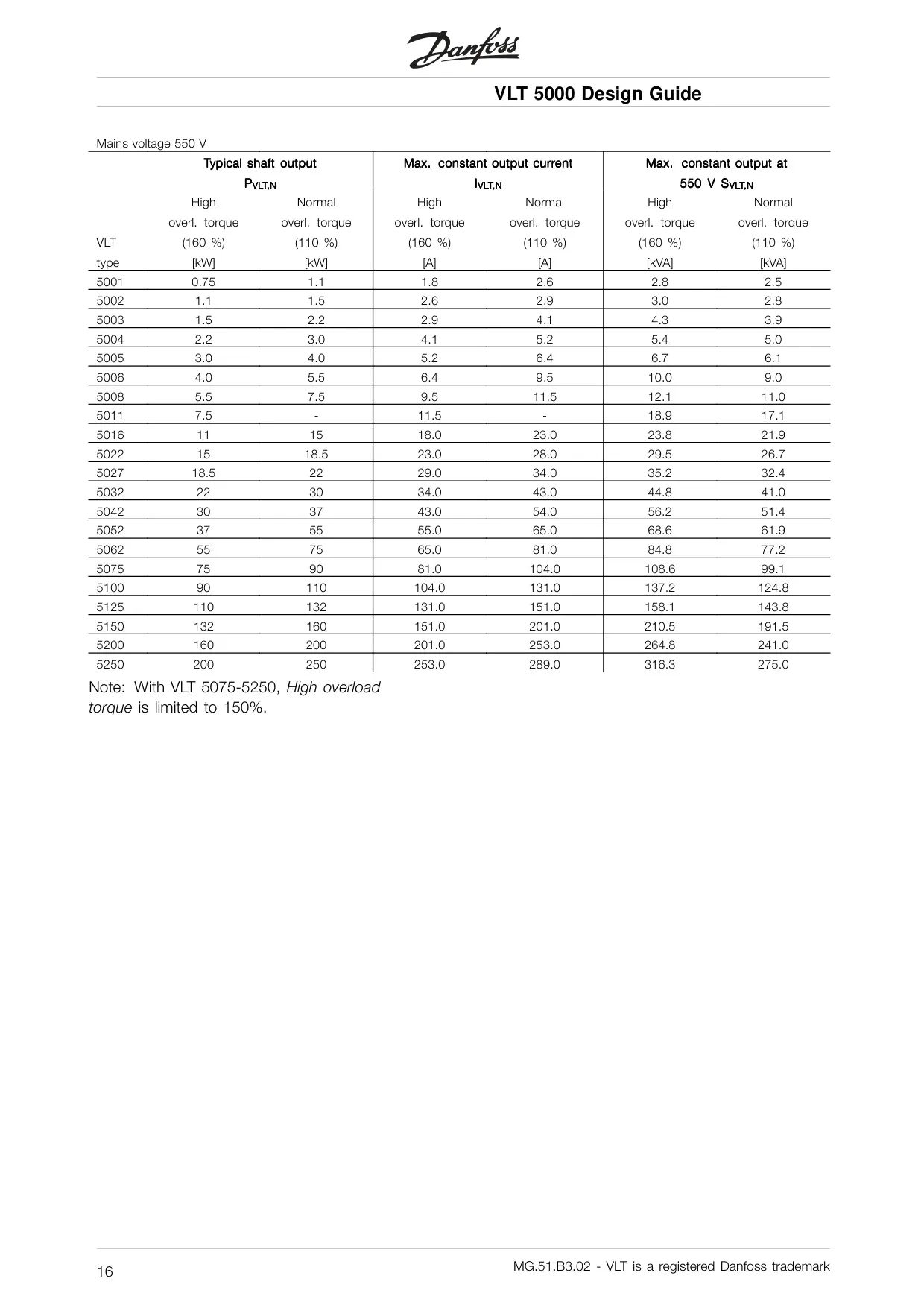
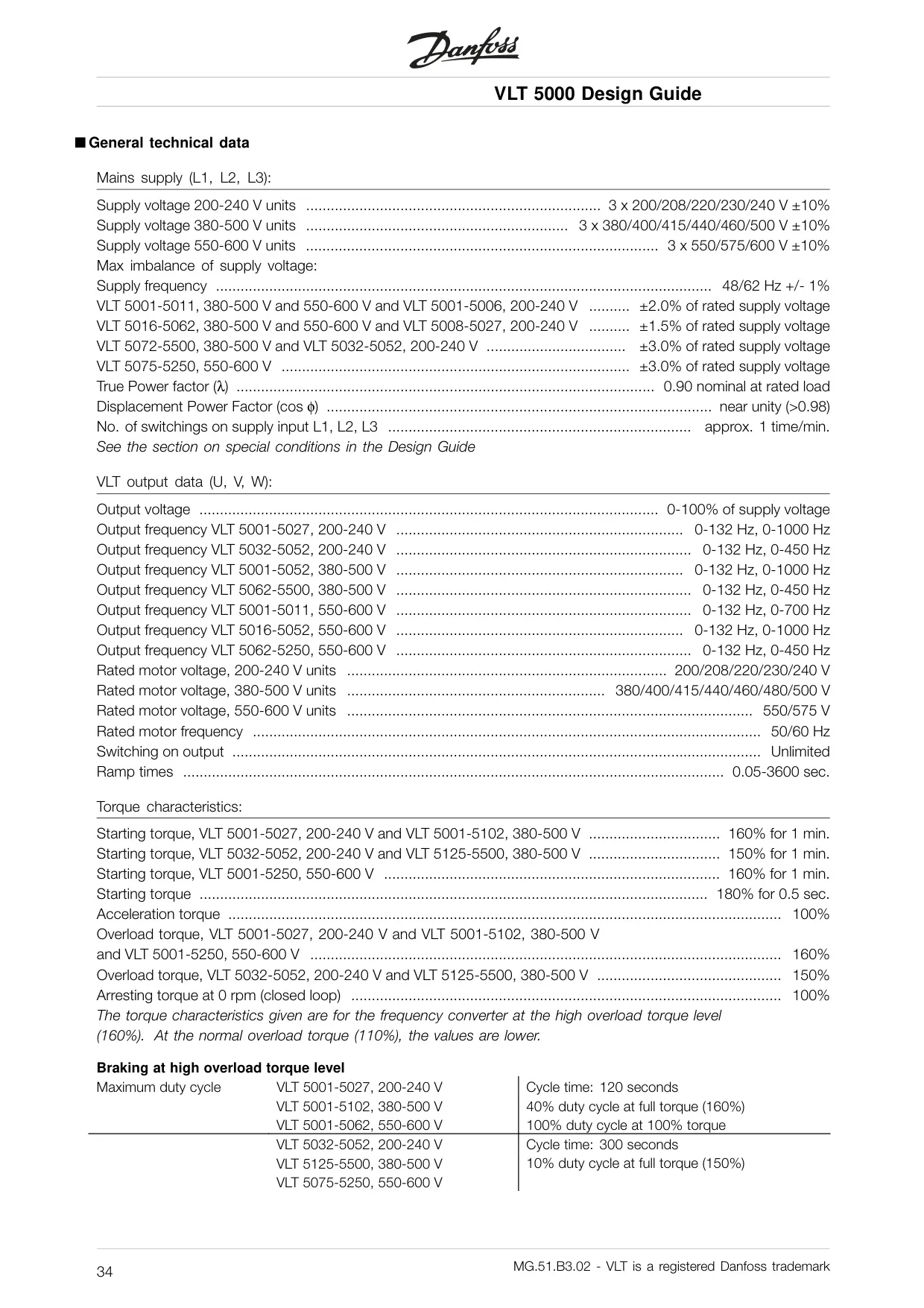
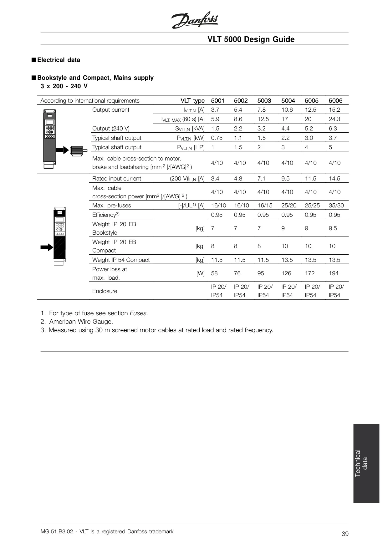
| Supply Voltage Range | 3 x 200-240 V ±10% 3 x 380-500 V ±10% 3 x 525-600 V ±10% 3 x 525-690 V ±10% |
| Supply Frequency | 48-62 Hz ±1 % |
| True Power Factor (λ) | 0.90 nominal at rated load |
| Max. Short-circuit Rating | 100,000 A |
| VLT Output Data | |
| Output Voltage | 0-100% of supply voltage |
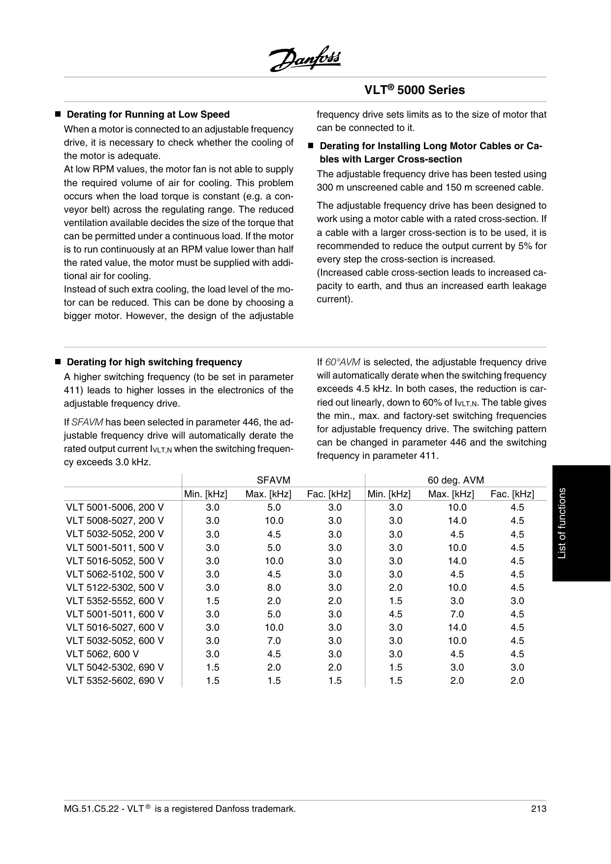
| Output Frequency Range | 0-132 Hz, 0-1000 Hz (model dependent) |
| Rated Motor Voltage (examples) | 200/208/220/230/240 V 380/400/415/440/460/480/500 V 525/550/575/600/690 V |
| Rated Motor Frequency | 50/60 Hz |
| Ramp Times | 0.05-3600 seconds |
| Starting Torque (High Overload) | 150-160% for 1 minute 180% for 0.5 seconds |
| Overload Torque (High Overload) | 160% |
| Overload Torque (Normal Overload) | 110% |
| Control Card - Digital Inputs | |
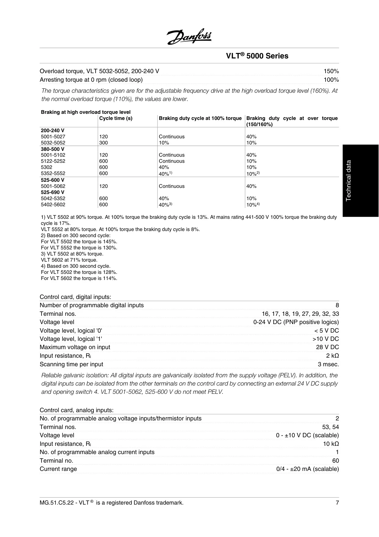
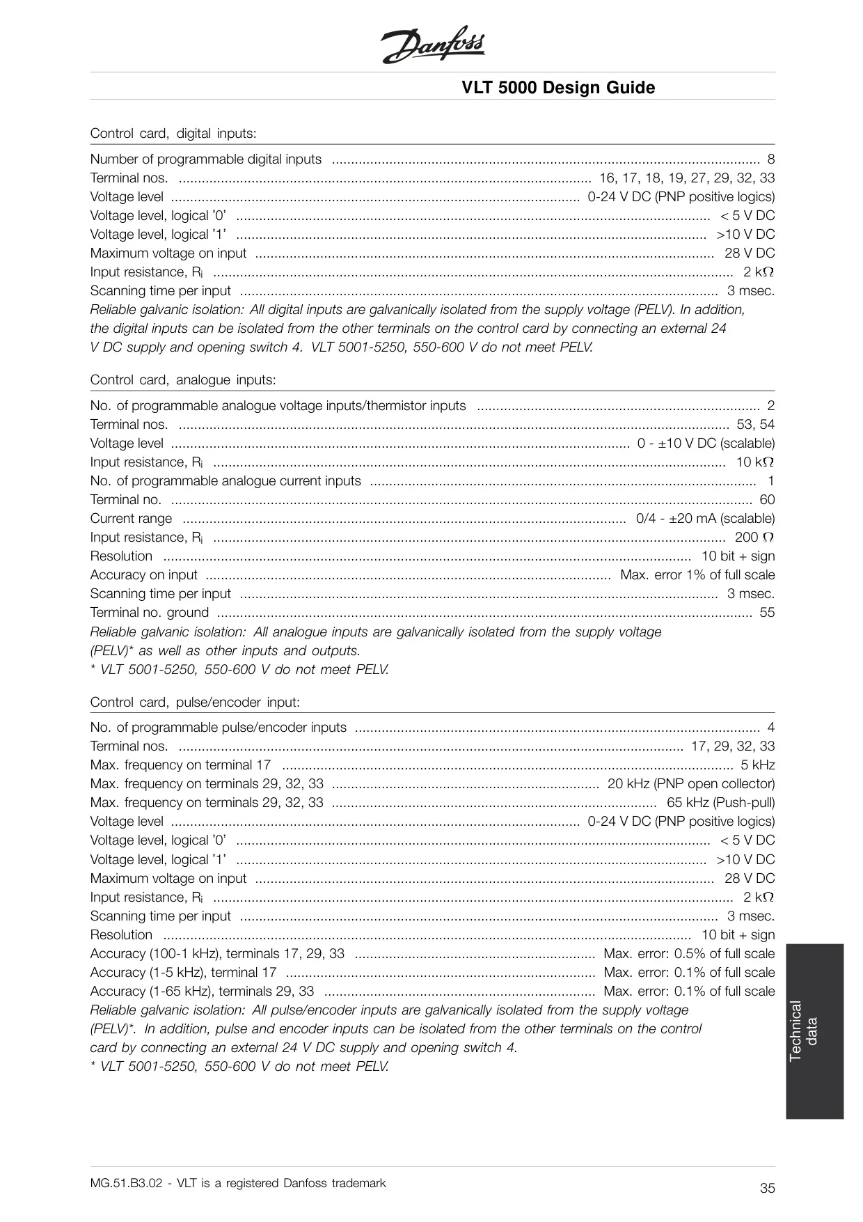
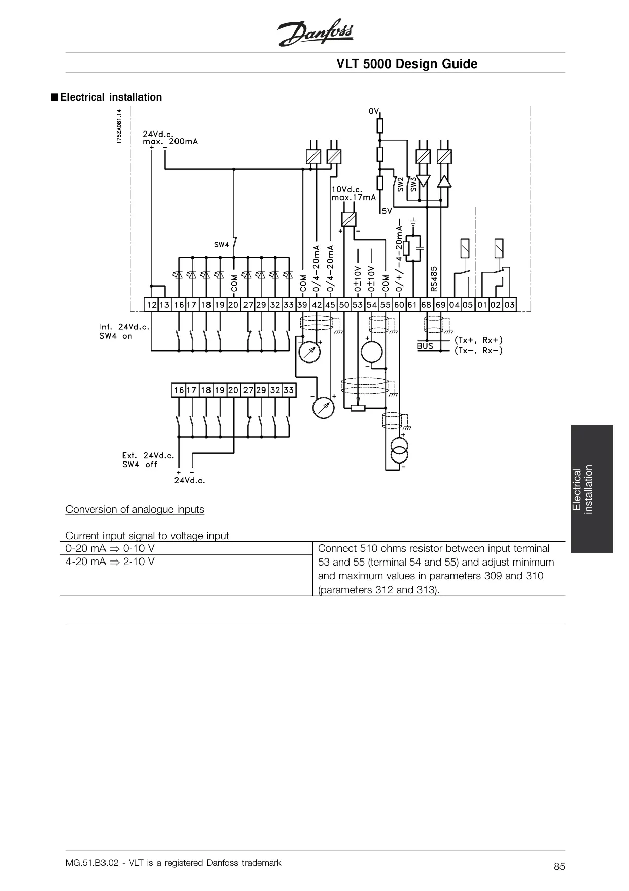
| Number of Programmable Inputs | 8 |
| Voltage Level | 0-24 V DC (PNP positive logics) |
| Max. Frequency (Term. 17) | 5 kHz |
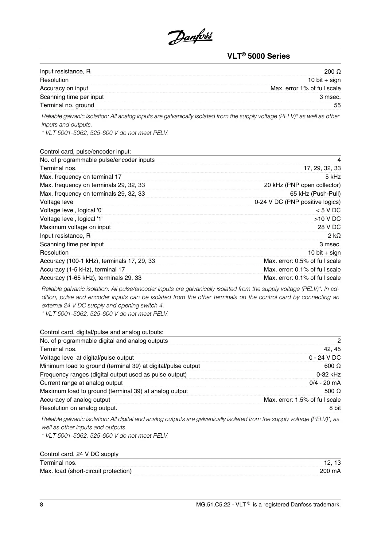
| Max. Frequency (Term. 29, 32, 33) | 20 kHz (PNP open collector) 65 kHz (Push-Pull) |
| Control Card - Analog Inputs | |
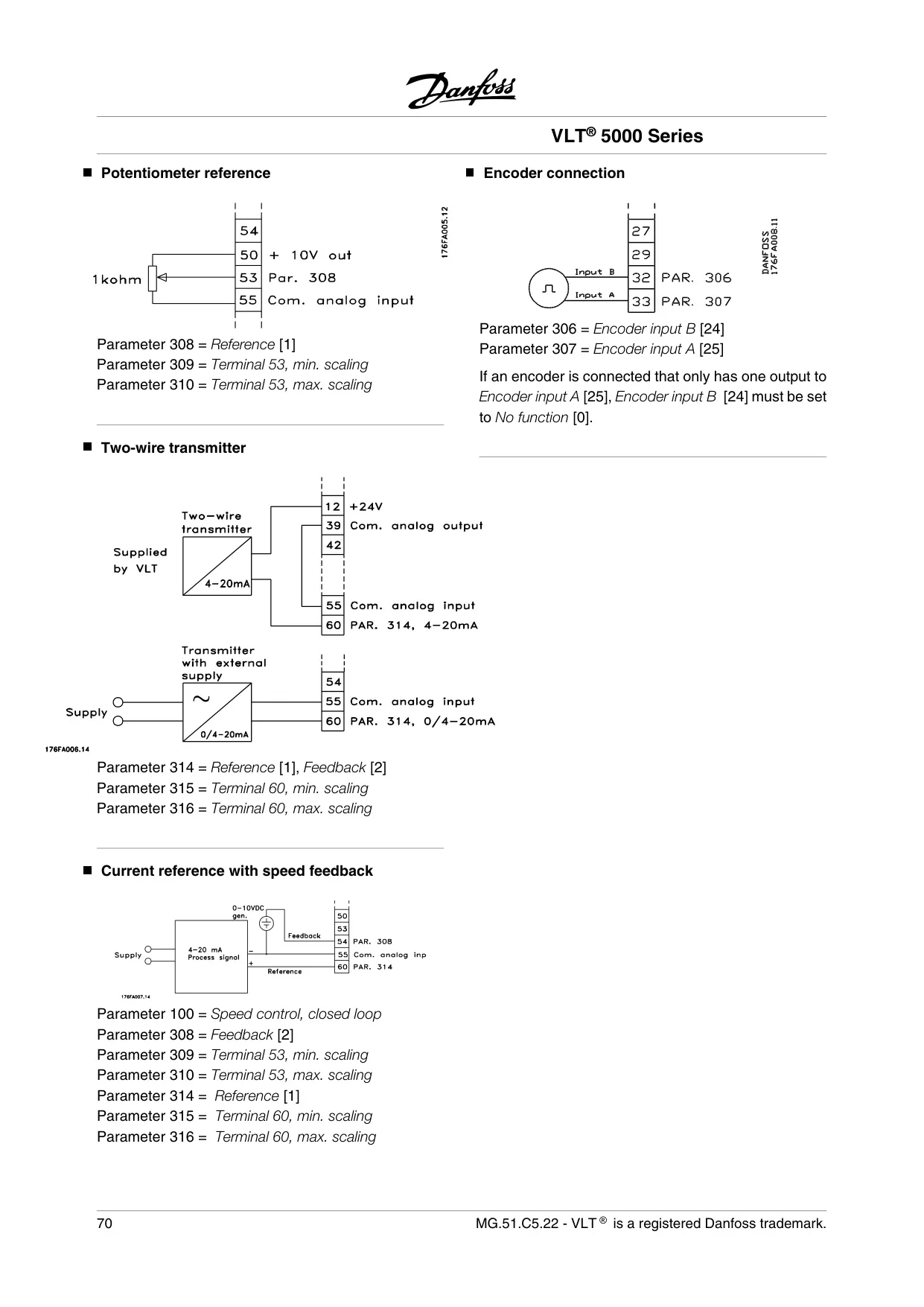
| Programmable Voltage Inputs | 2 (0-±10 V DC, scalable) |
| Programmable Current Inputs | 1 (0/4-±20 mA, scalable) |
| Resolution | 10 bit + sign |
| Accuracy on Input | Max. error 1% of full scale |
| Control Card - Outputs | |
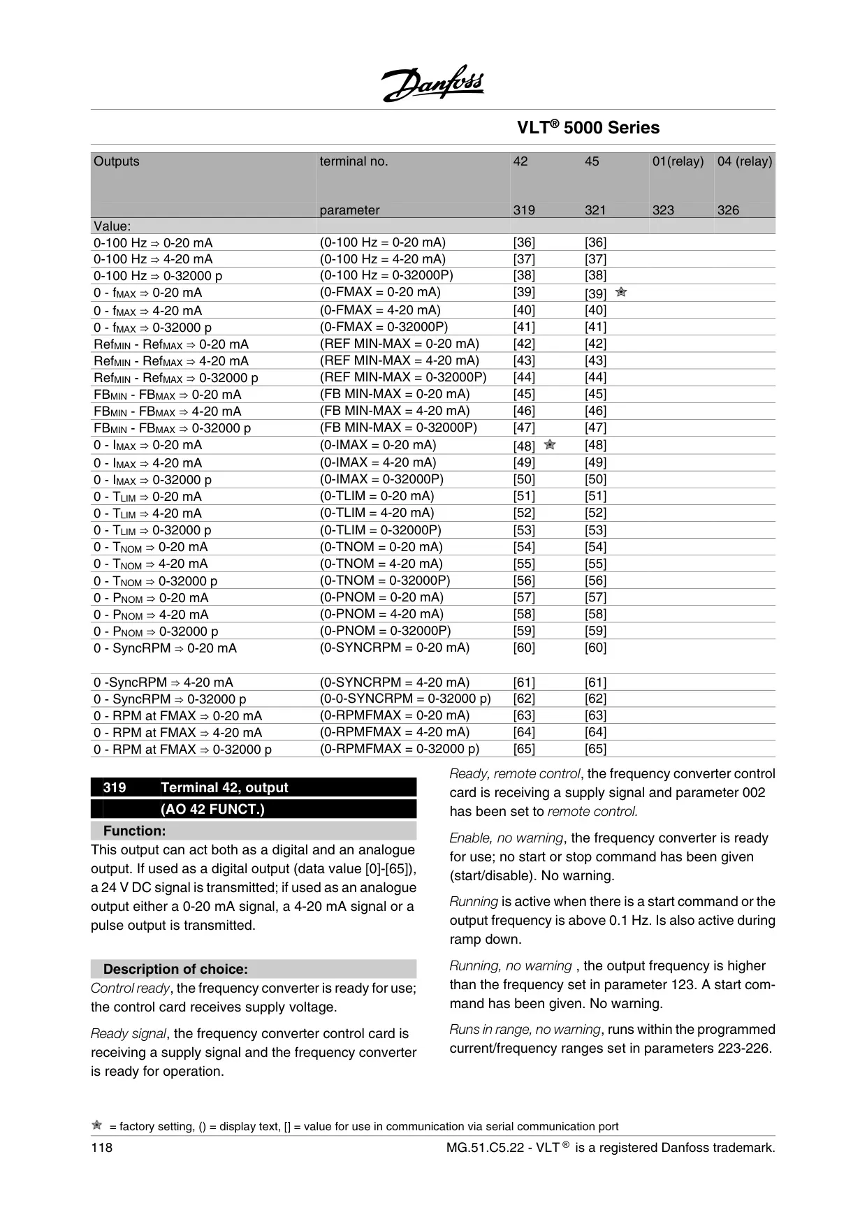
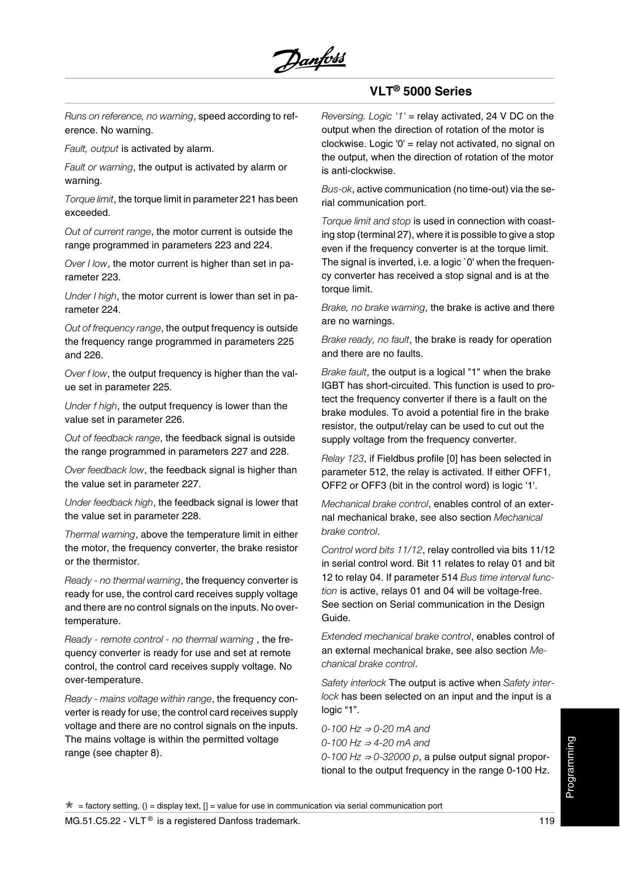
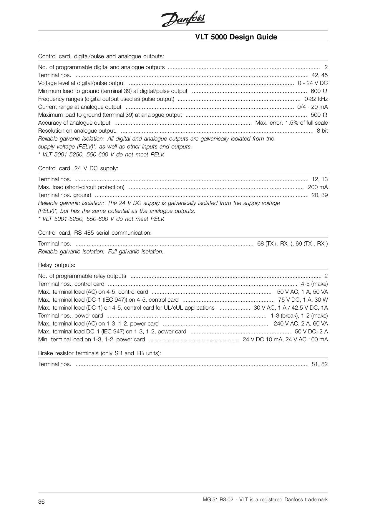
| Programmable Digital/Analog Outputs | 2 (0-24 V DC, 0/4-20 mA) |
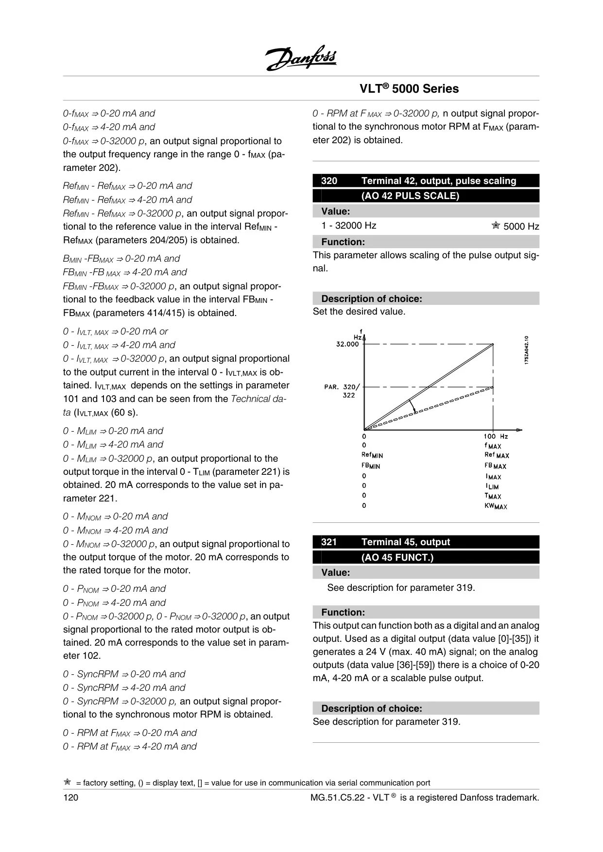
| Frequency Range (Pulse Output) | 0-32 kHz |
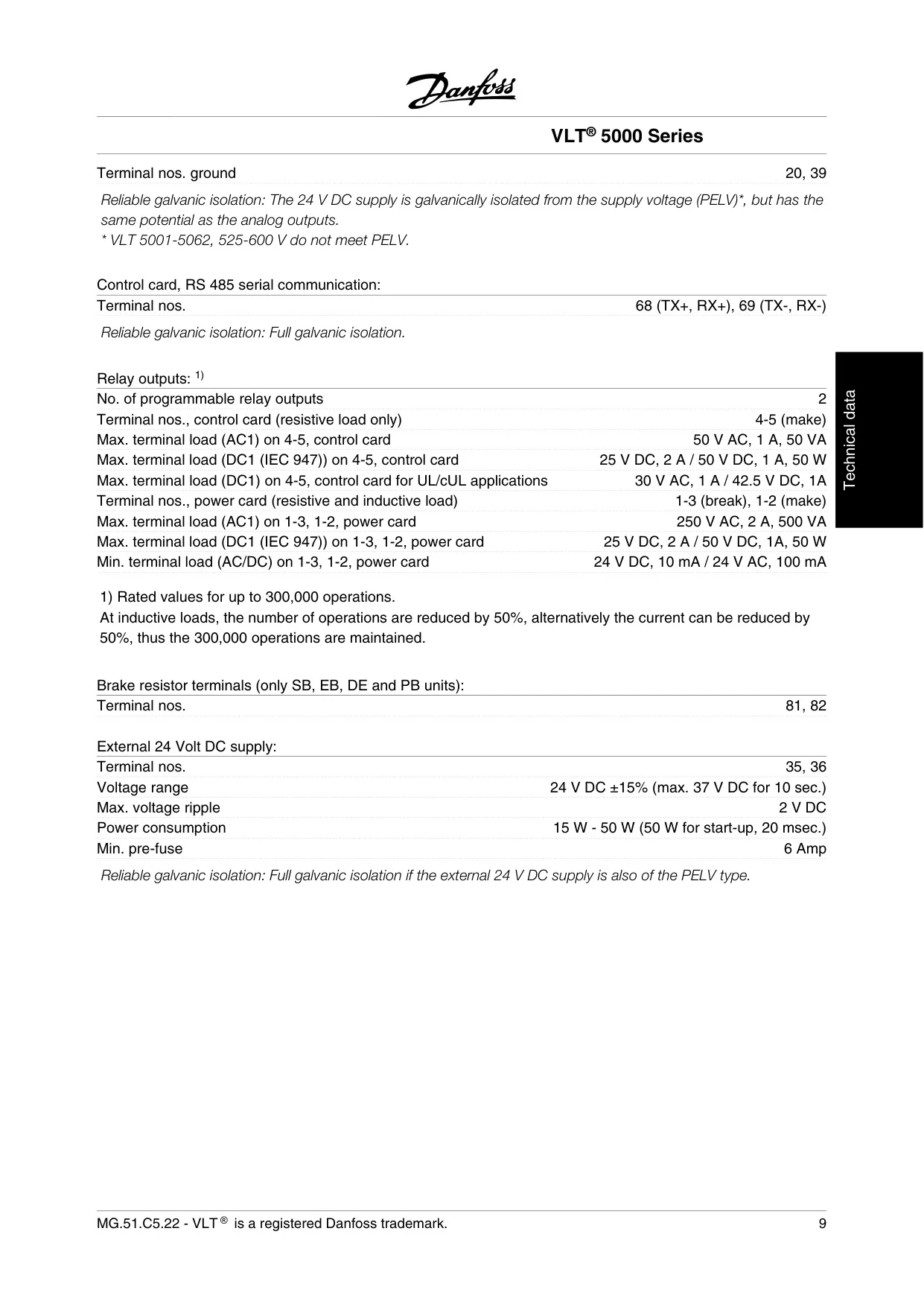
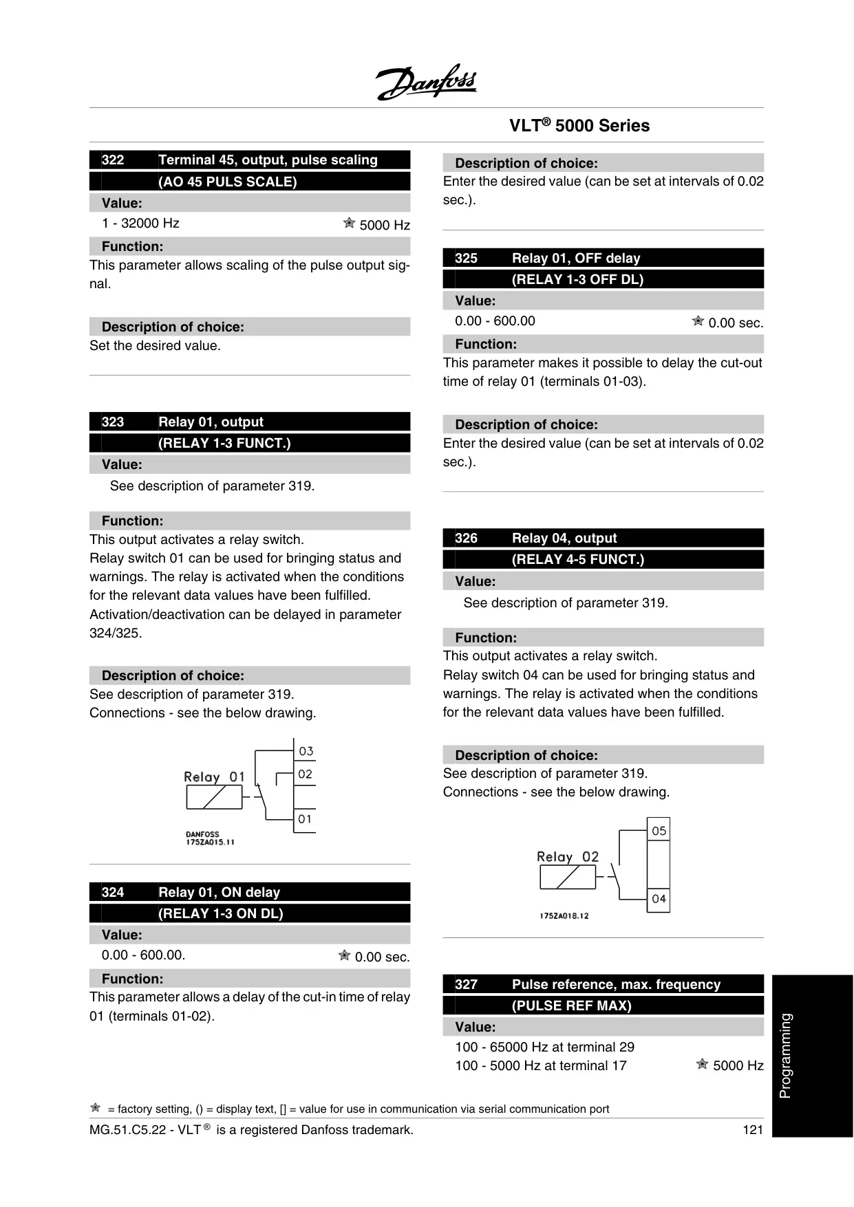
| Programmable Relay Outputs | 2 (up to 250 V AC, 2 A) |
| Cable Requirements | |
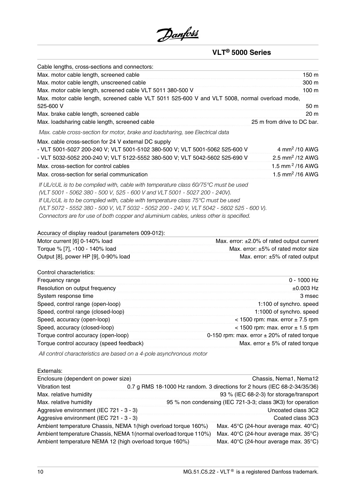
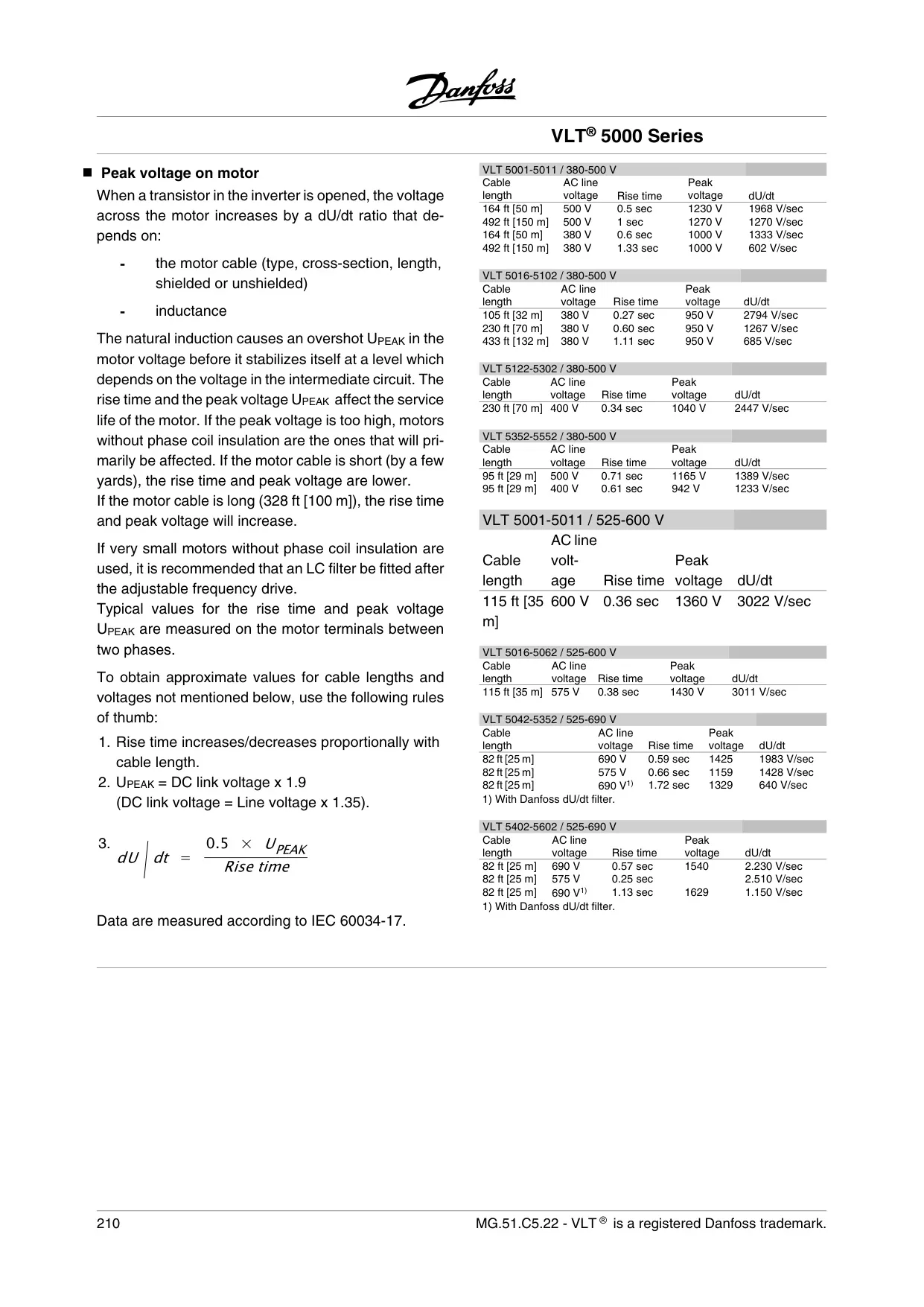
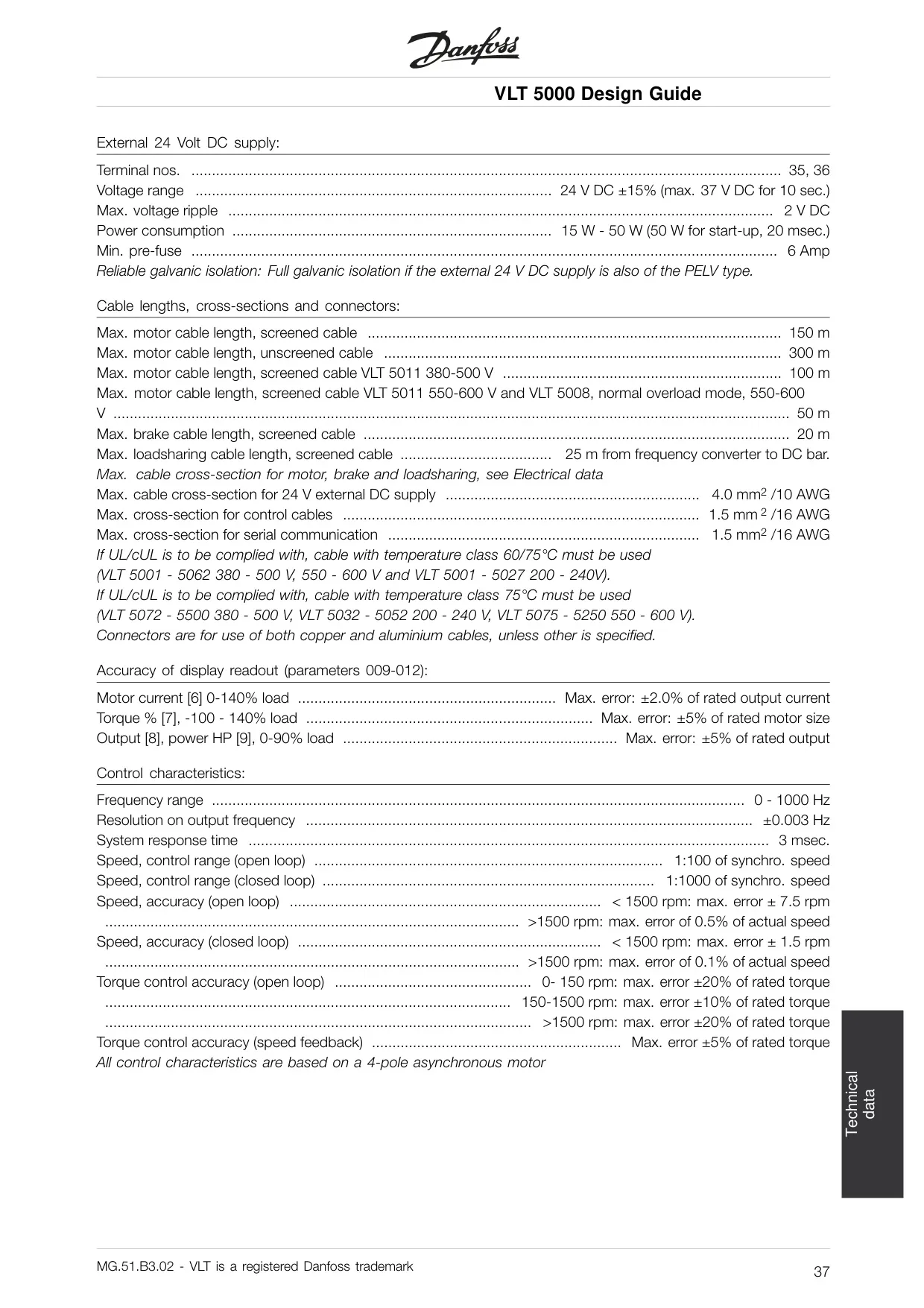
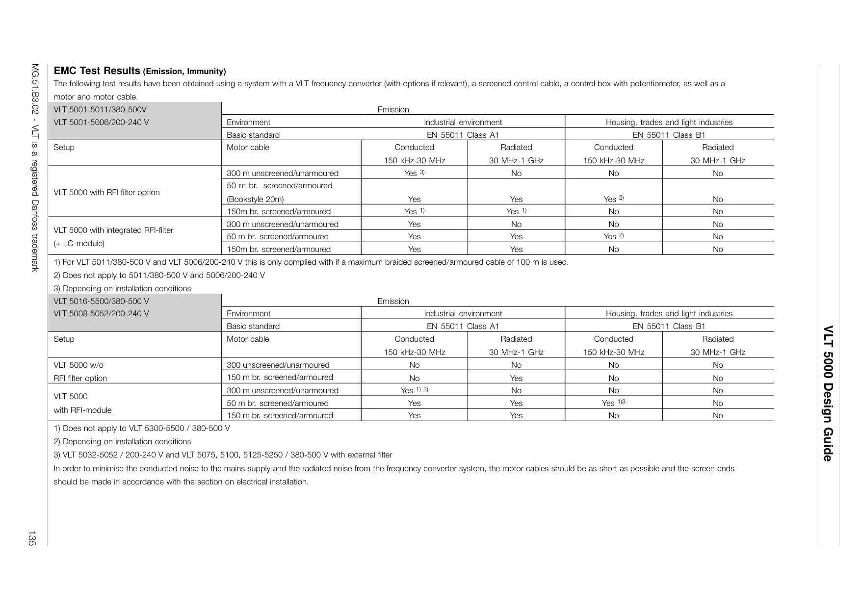
| Max. Motor Cable Length (screened) | 150 m (model dependent) |
| Max. Motor Cable Length (unscreened) | 300 m |
| Max. Brake Cable Length (screened) | 20 m |
| Max. Control Cable Cross-section | 1.5 mm² / 16 AWG |
| Environmental Conditions | |
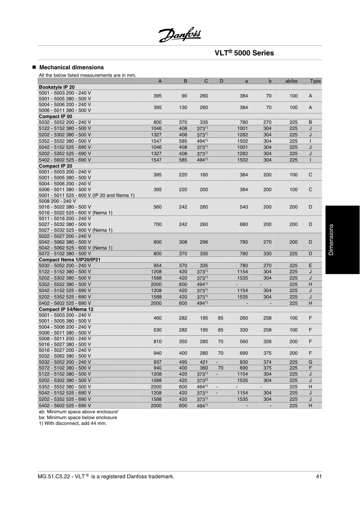
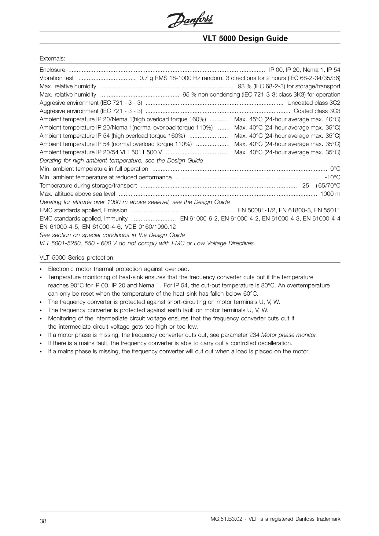
| Enclosure Options | Chassis, NEMA 1, NEMA 12 (IP 20, IP 54) |
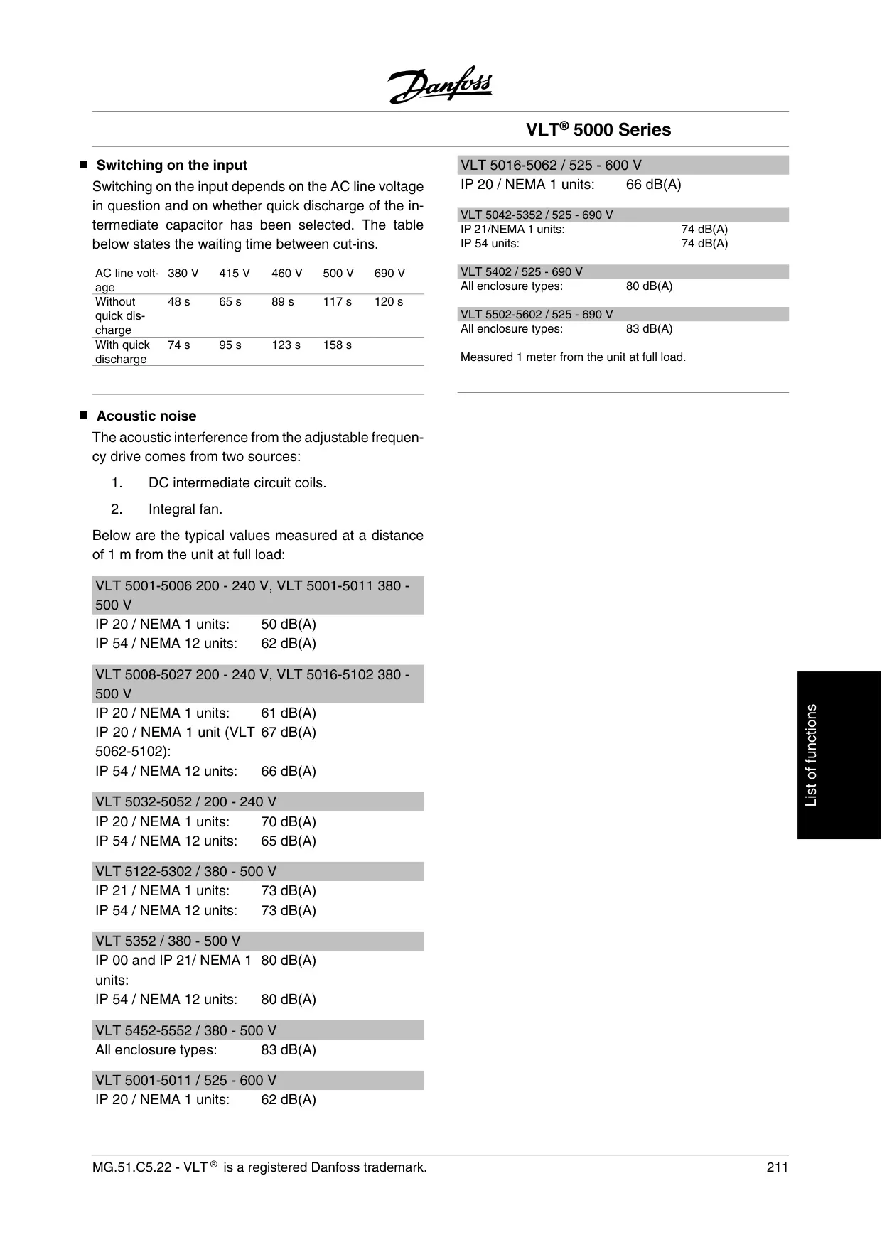
| Max. Relative Humidity | 95% non-condensing (operation) |
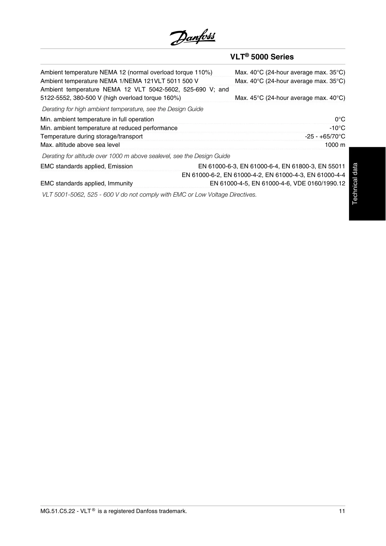
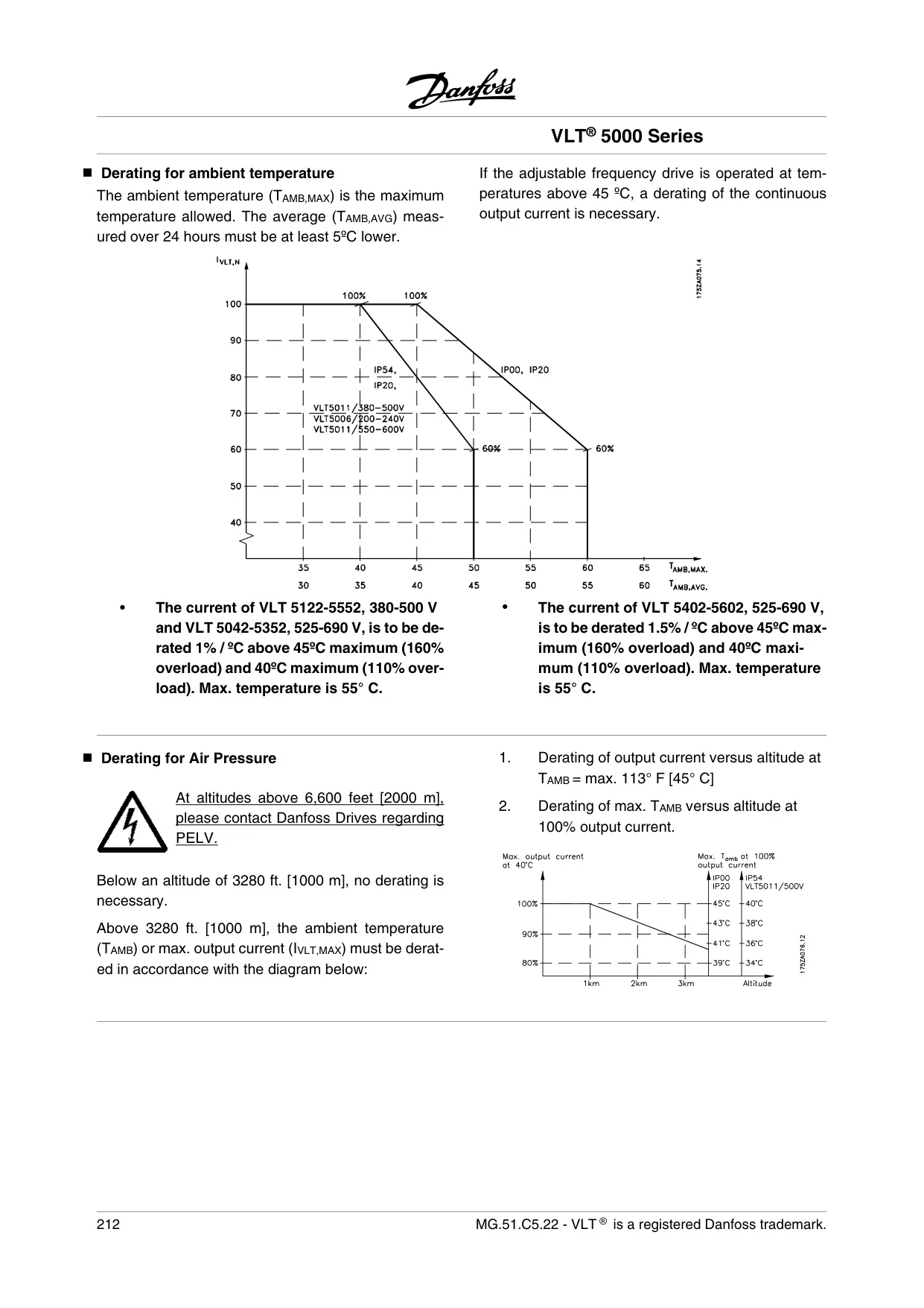
| Ambient Temperature (High Overload) | Max. 45°C (24-hour average max. 40°C) |
| Ambient Temperature (Normal Overload) | Max. 40°C (24-hour average max. 35°C) |
| Min. Ambient Temperature (full operation) | 0°C |
| Max. Altitude Above Sea Level | 1000 m (derating above) |
Danfoss VLT 5000 VFD Details
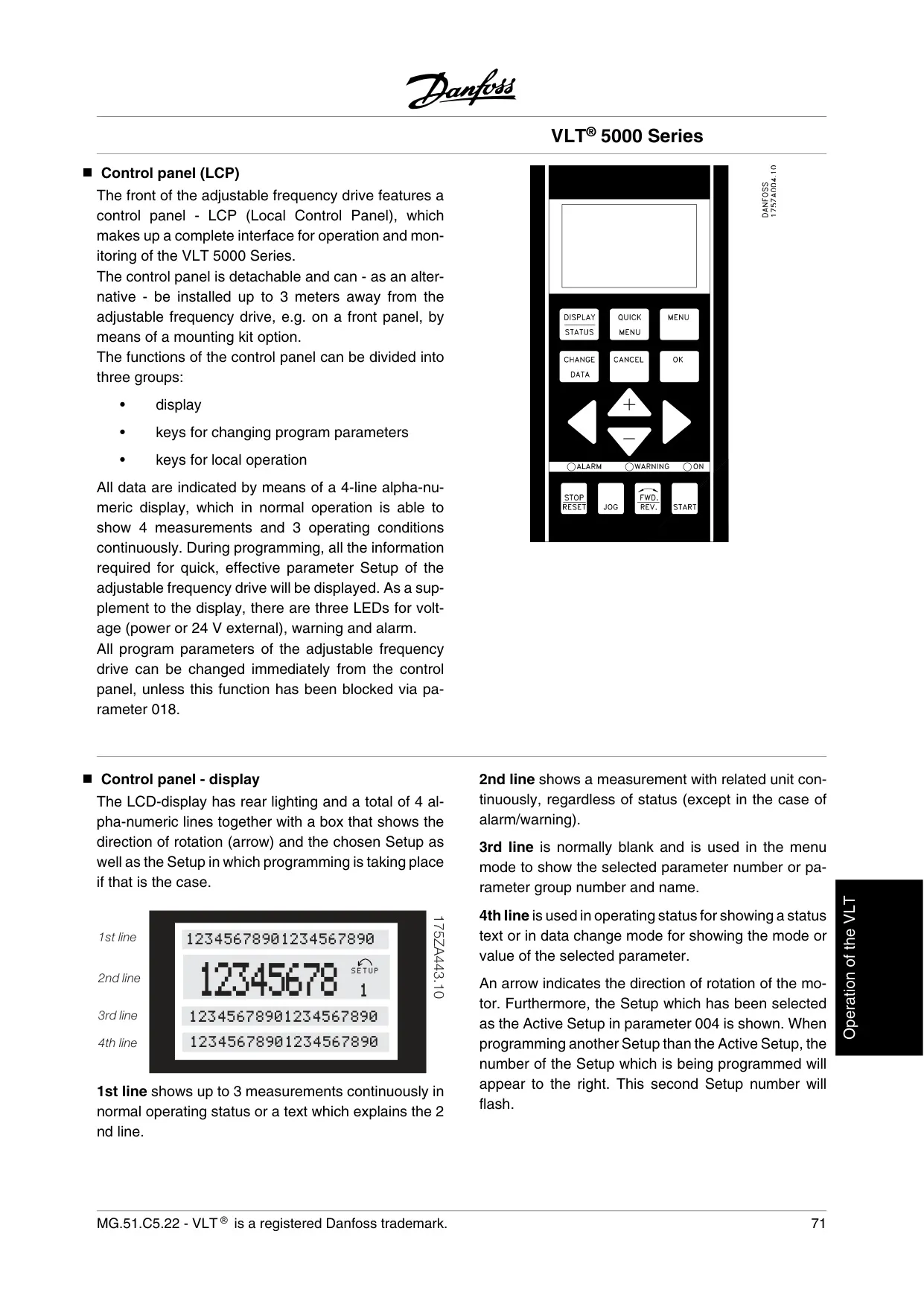
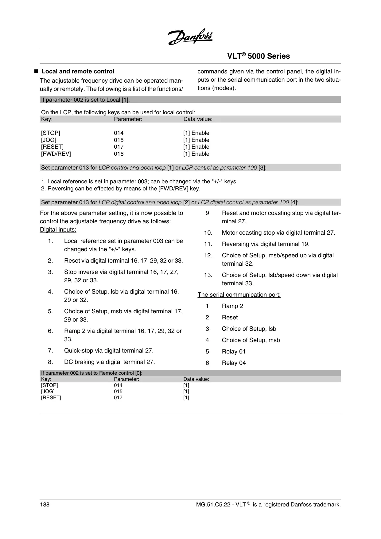
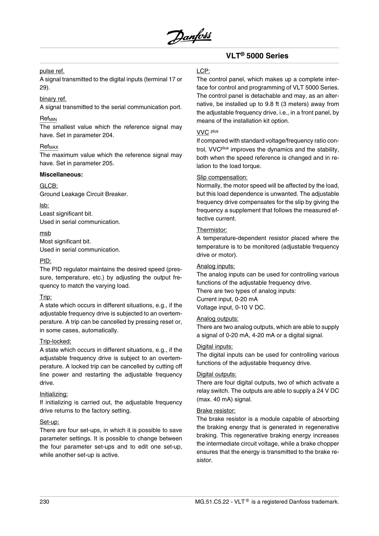
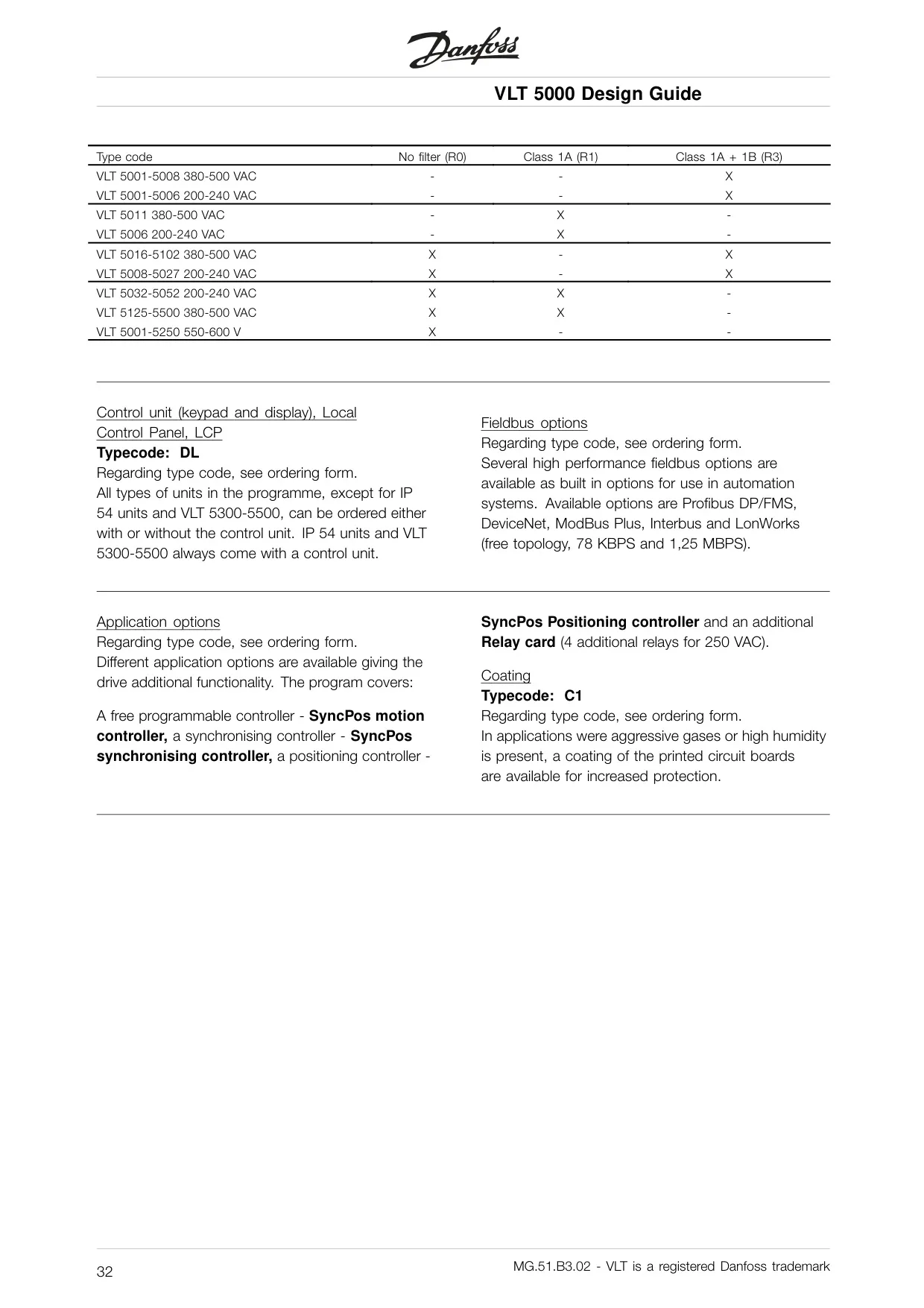
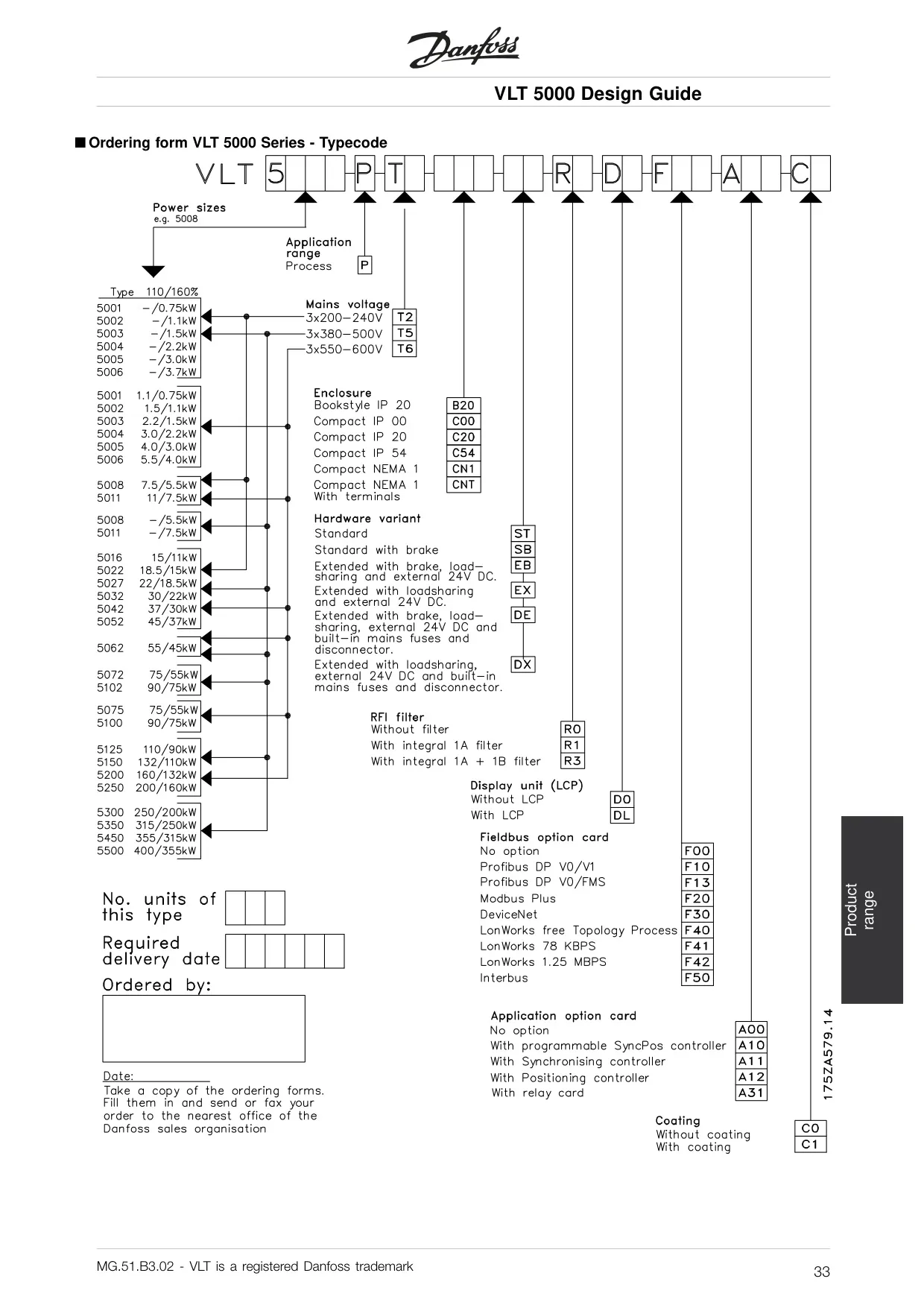
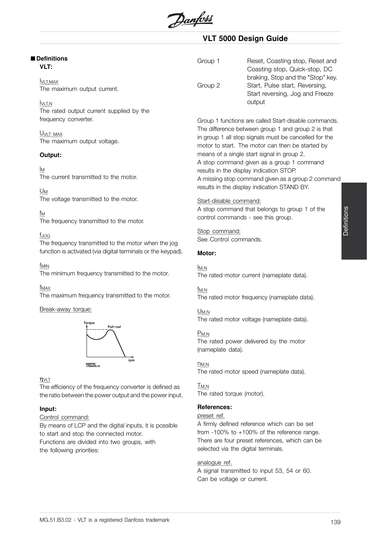
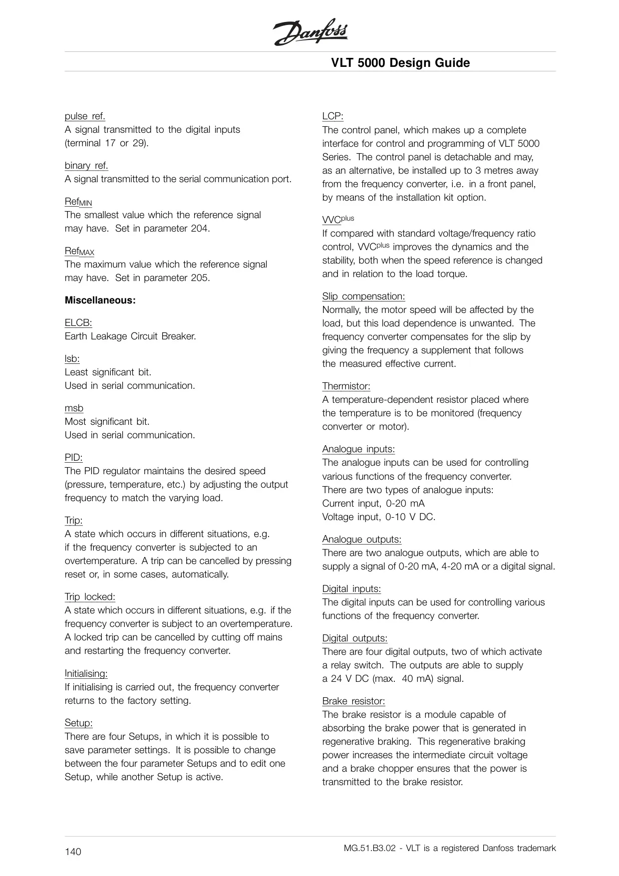
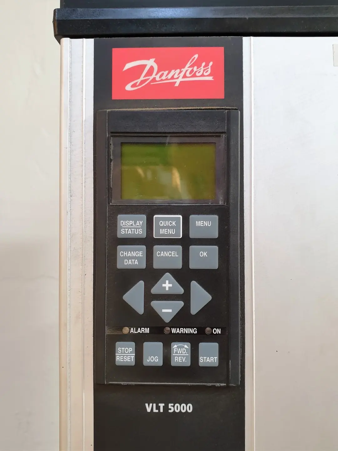
The Danfoss VLT 5000 series offers a robust and versatile solution for industrial motor control, designed with extensive programming and diagnostic capabilities. At its core, the drive features a Local Control Panel (LCP) that acts as a complete interface for both operation and monitoring. This LCP is detachable, allowing for remote installation up to three meters away, enhancing flexibility in system design and accessibility for users.
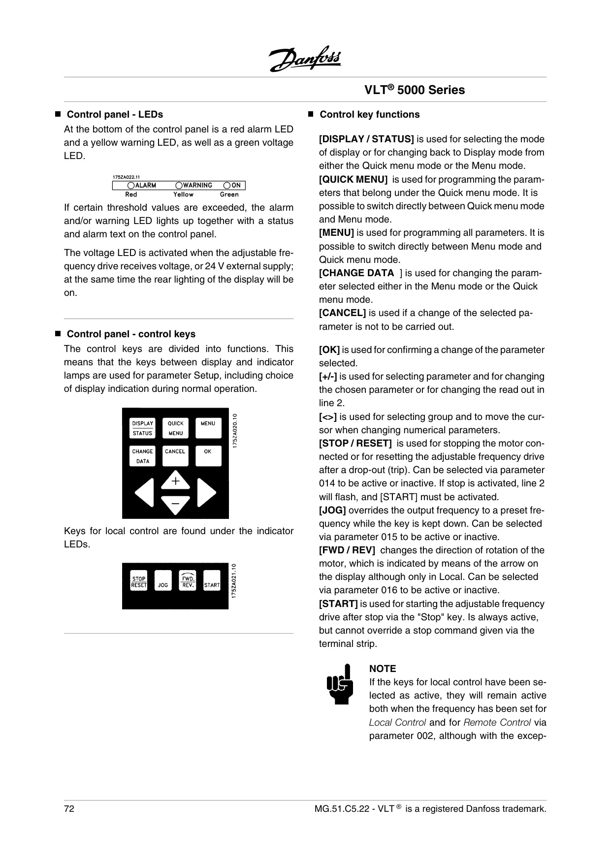
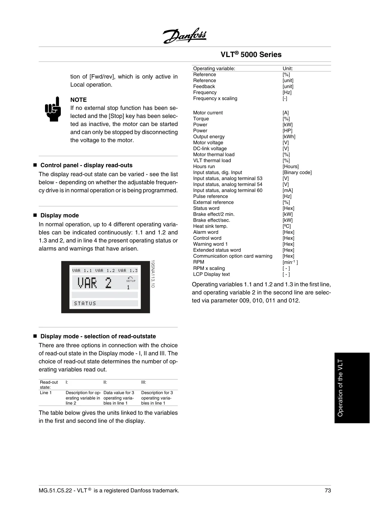
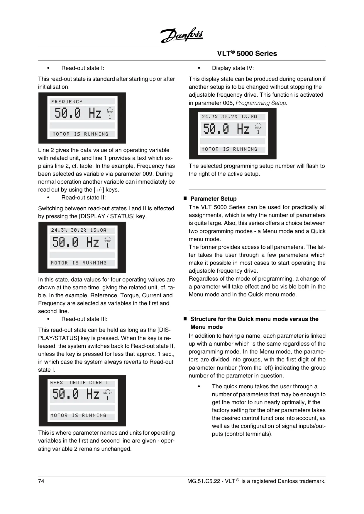
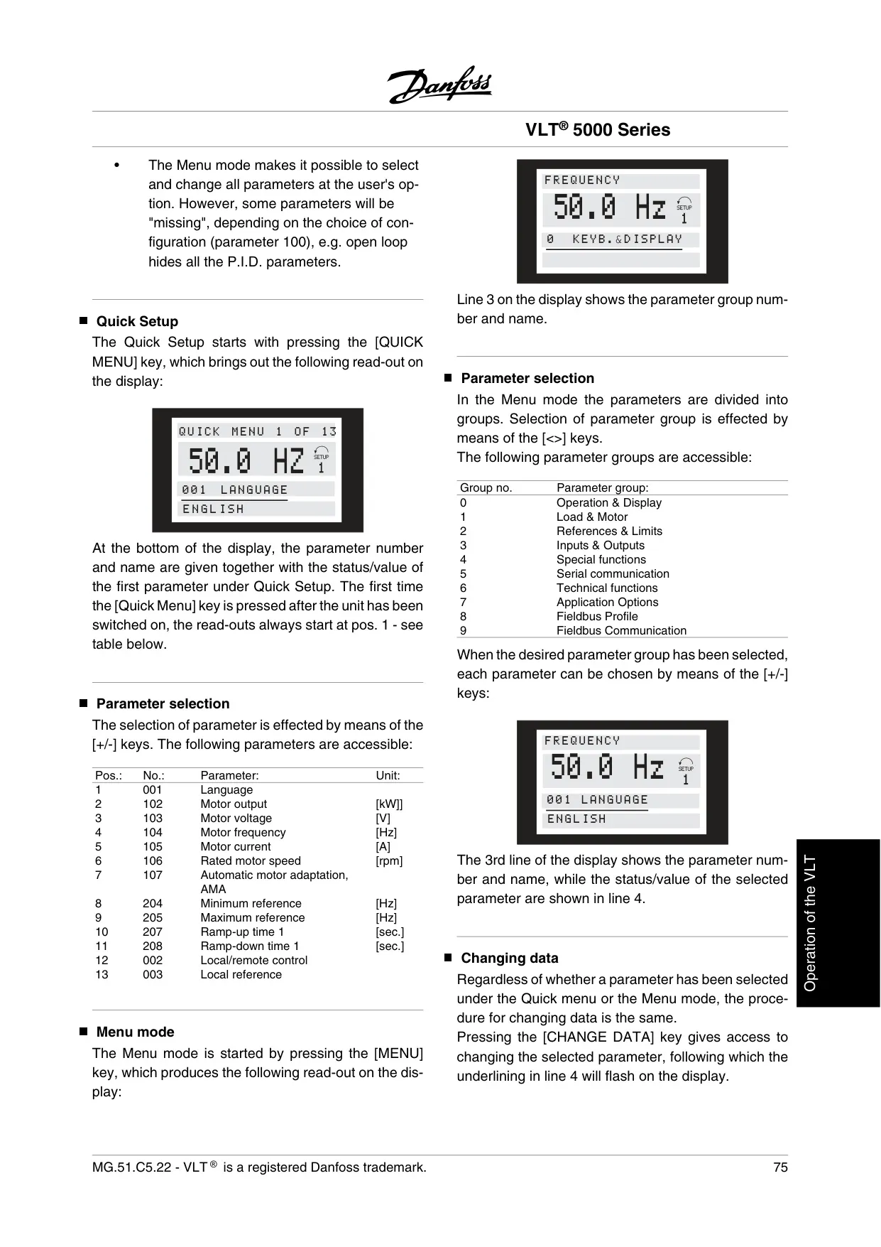
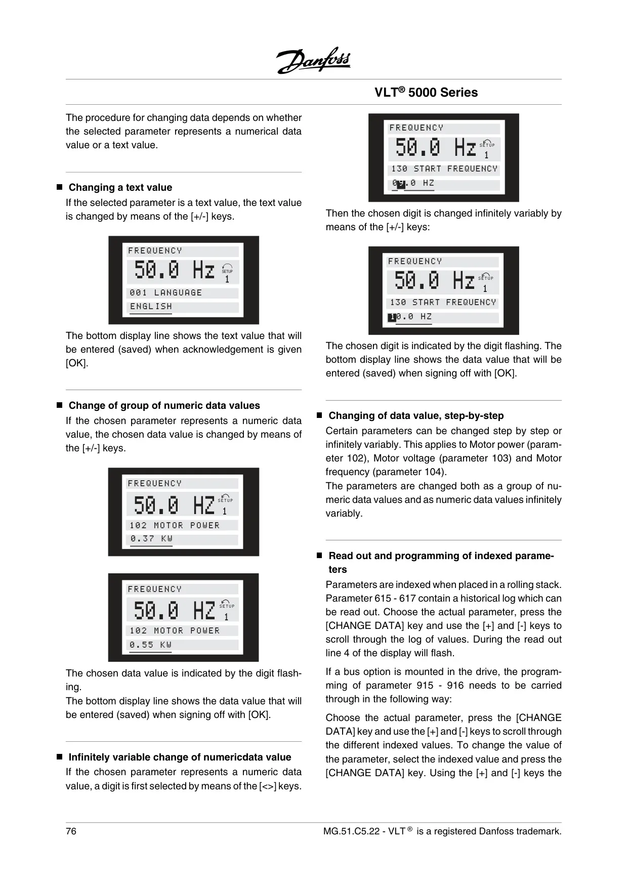
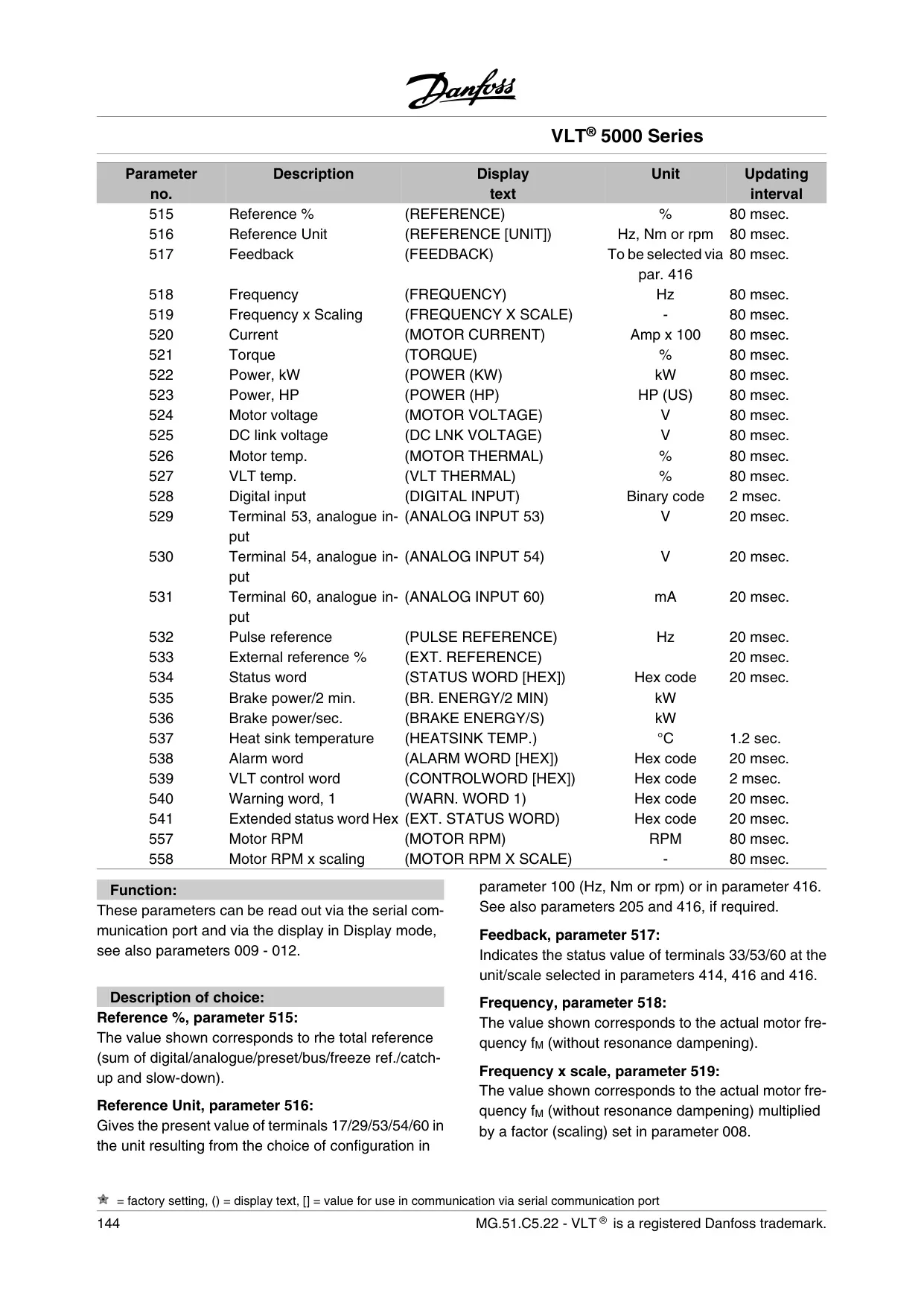
The LCP boasts a 4-line alphanumeric display with rear lighting, providing continuous feedback on up to four measurements and three operating conditions. Complementing the display are LEDs for voltage, warning, and alarm status, ensuring immediate visual cues for operational states. Control keys are intuitively grouped for parameter setup and local operation, simplifying navigation and adjustments.
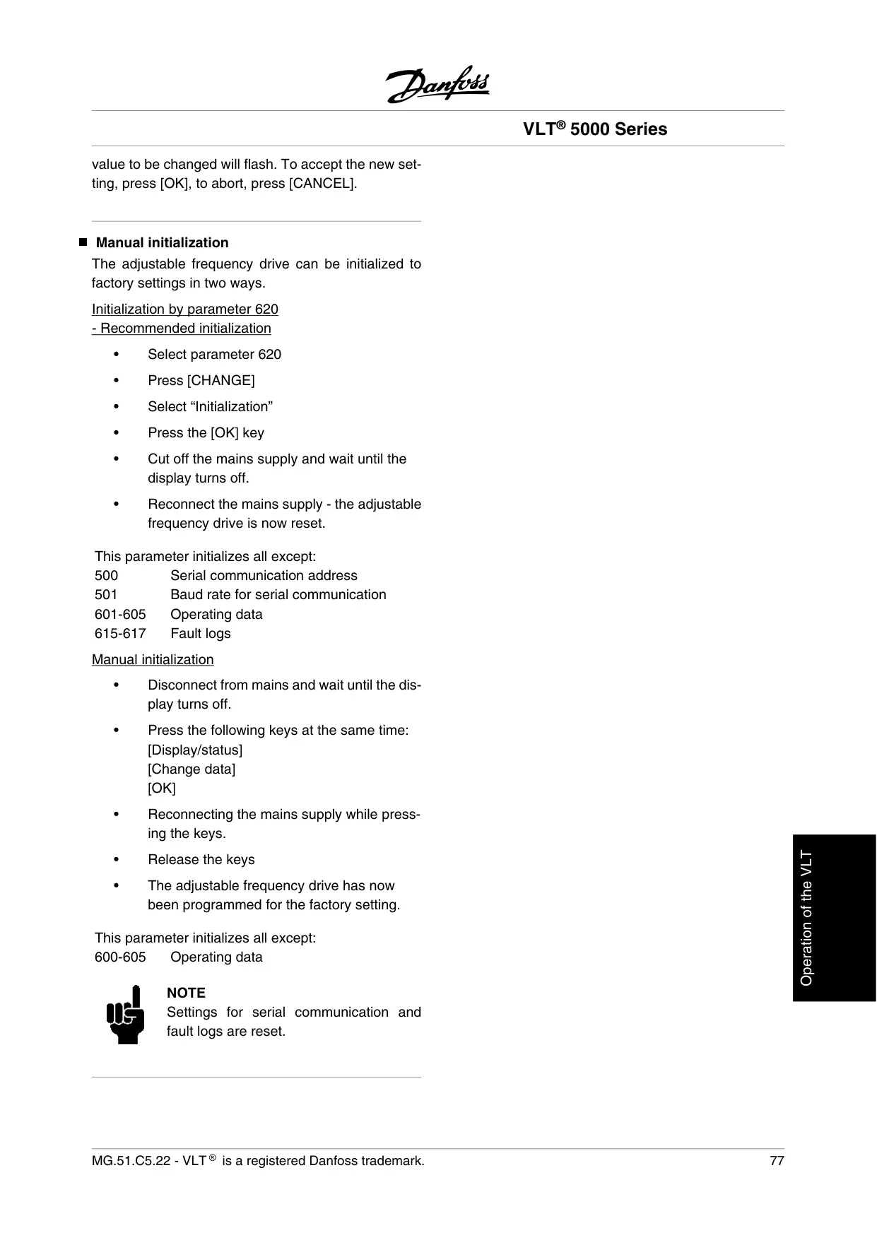
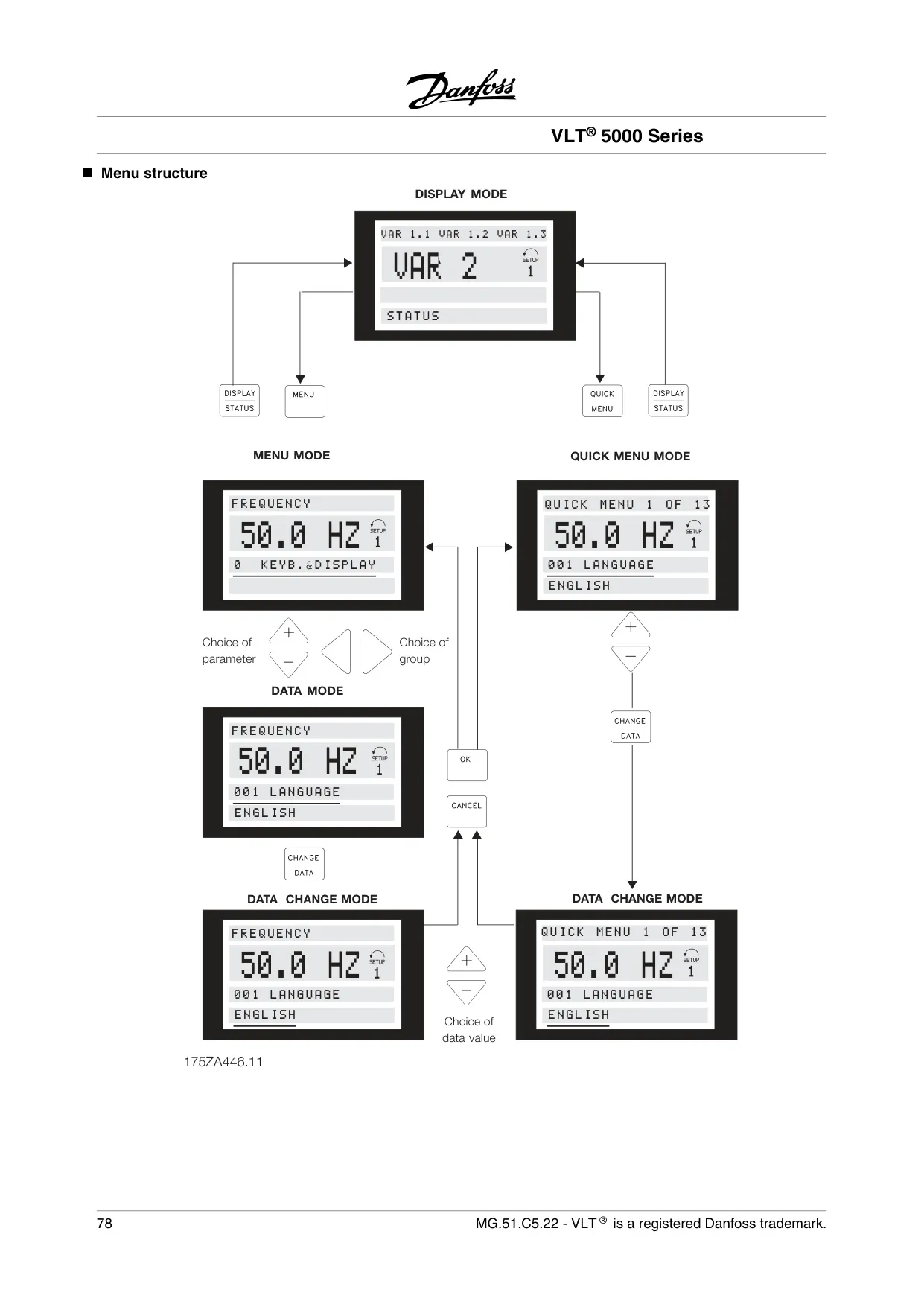
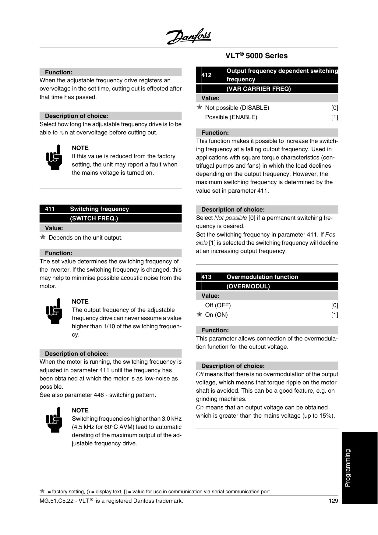
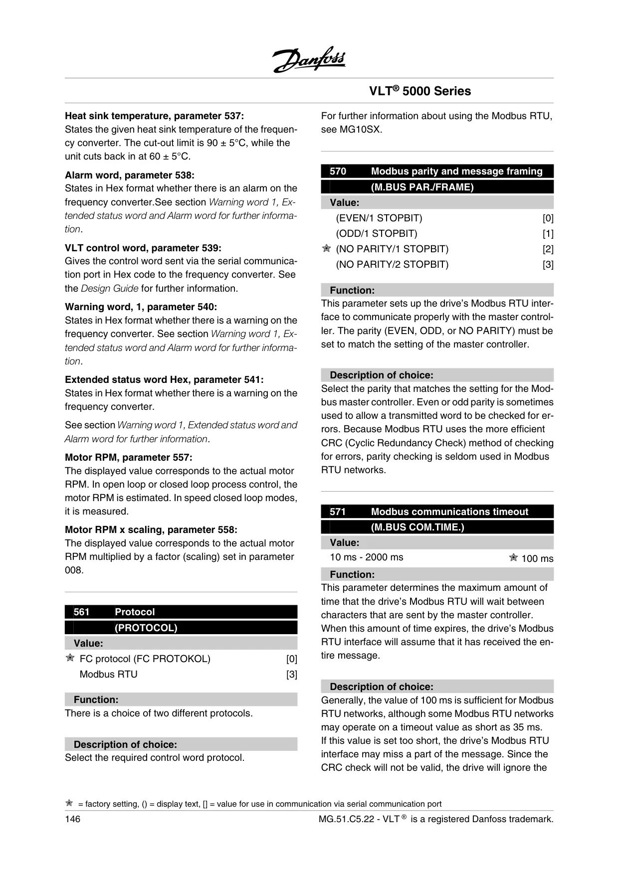
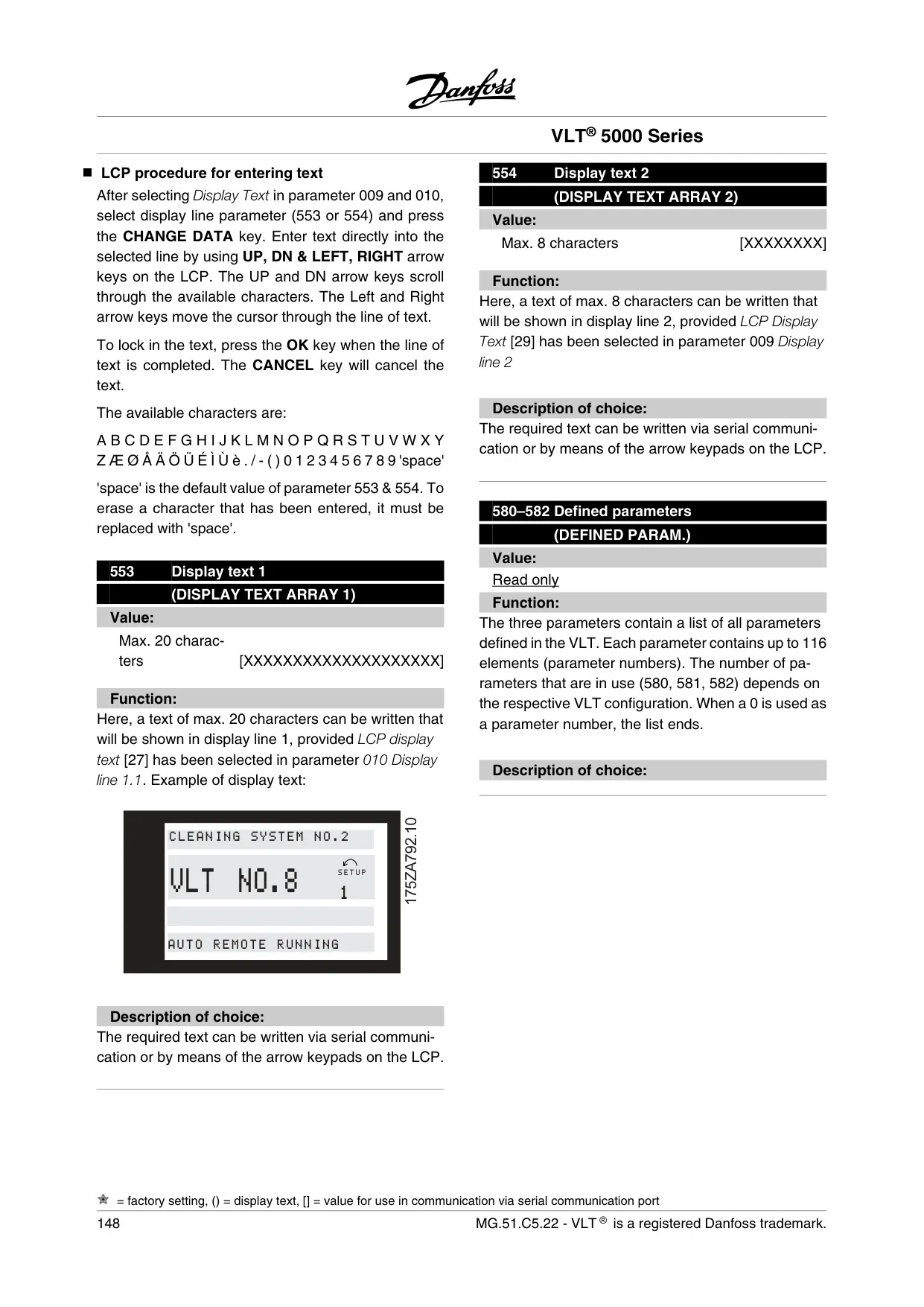
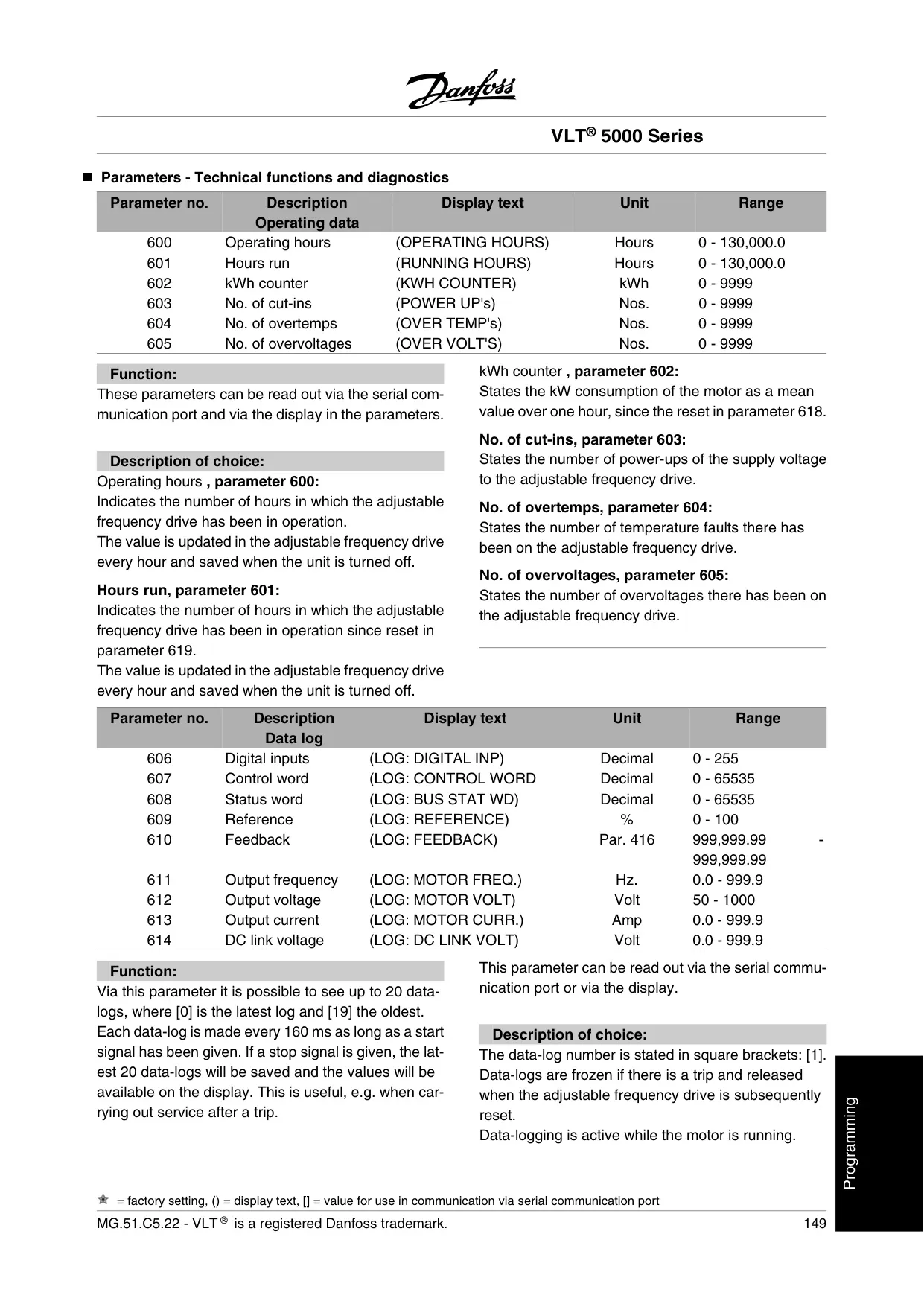
Programming the VLT 5000 is streamlined through two modes: a "Quick Setup" for essential parameters, enabling rapid deployment in most applications, and a comprehensive "Menu Mode" for full access to all adjustable parameters. This dual approach caters to both novice users and experienced technicians, ensuring efficient configuration tailored to specific needs.
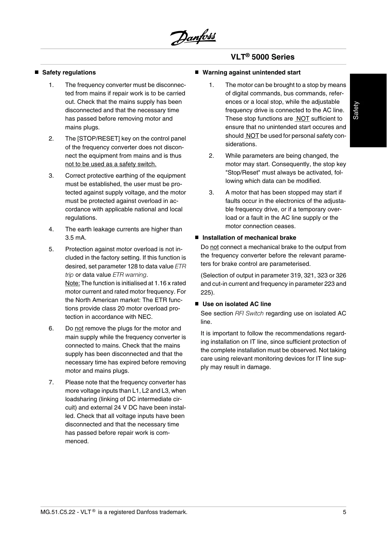
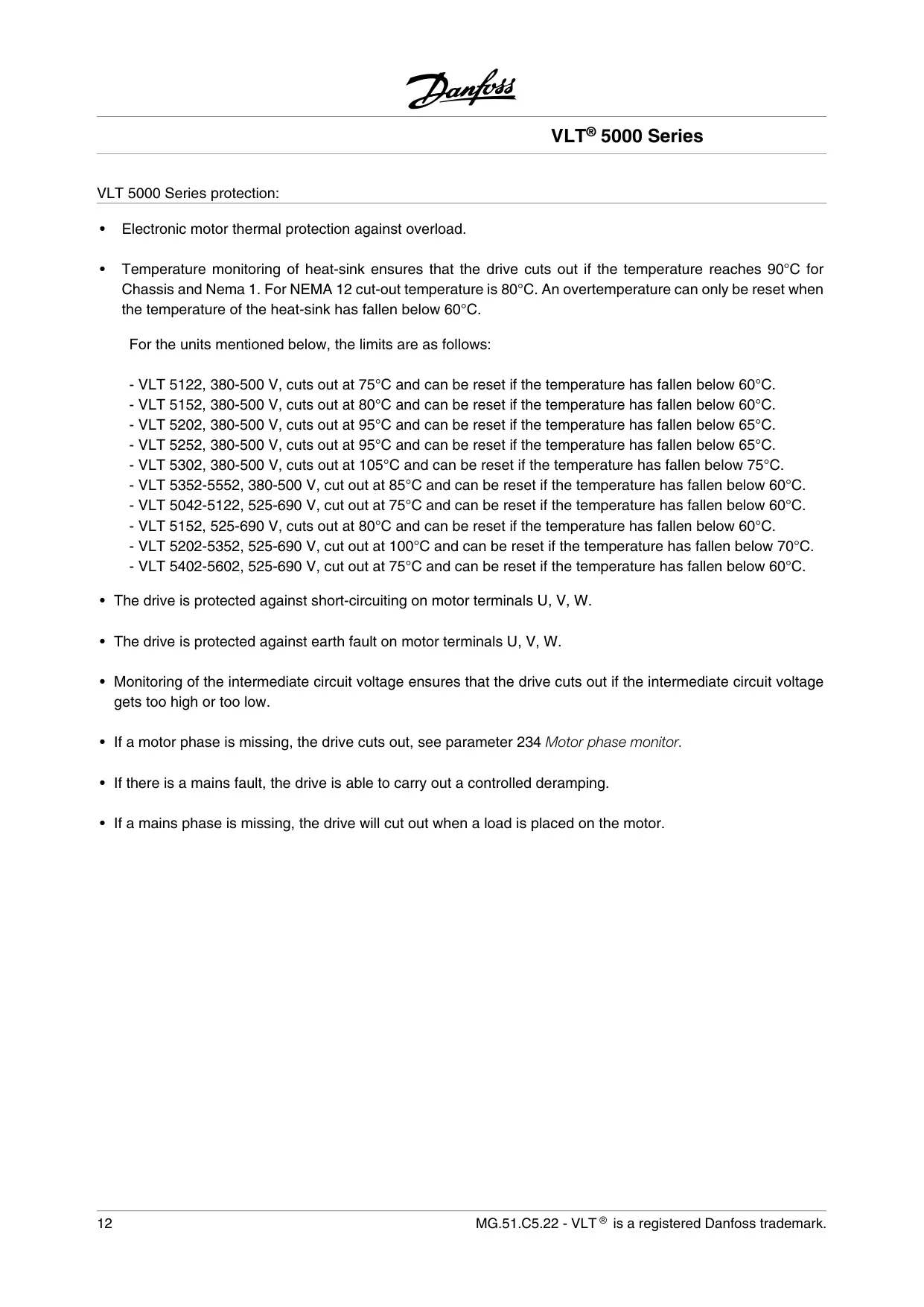
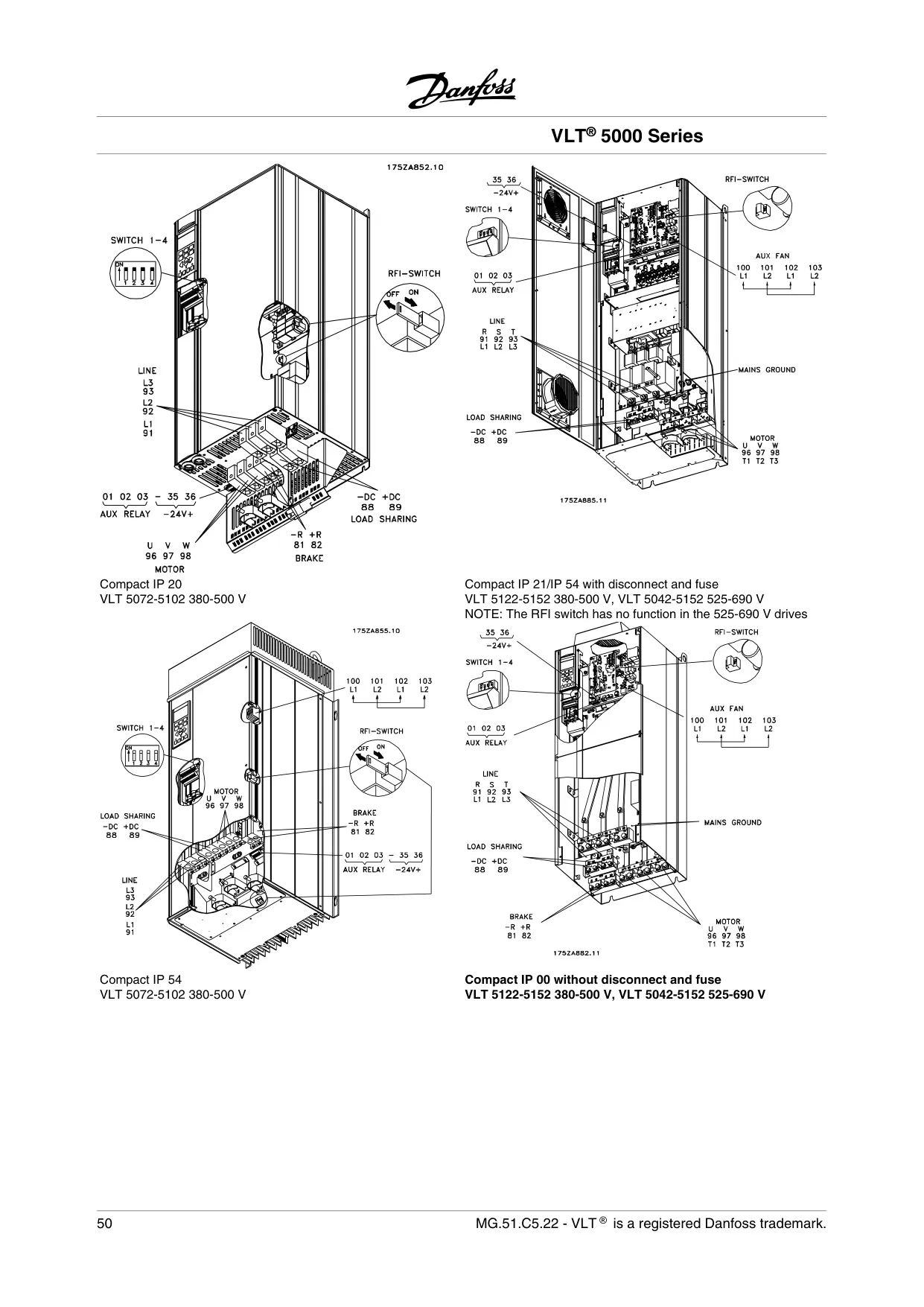
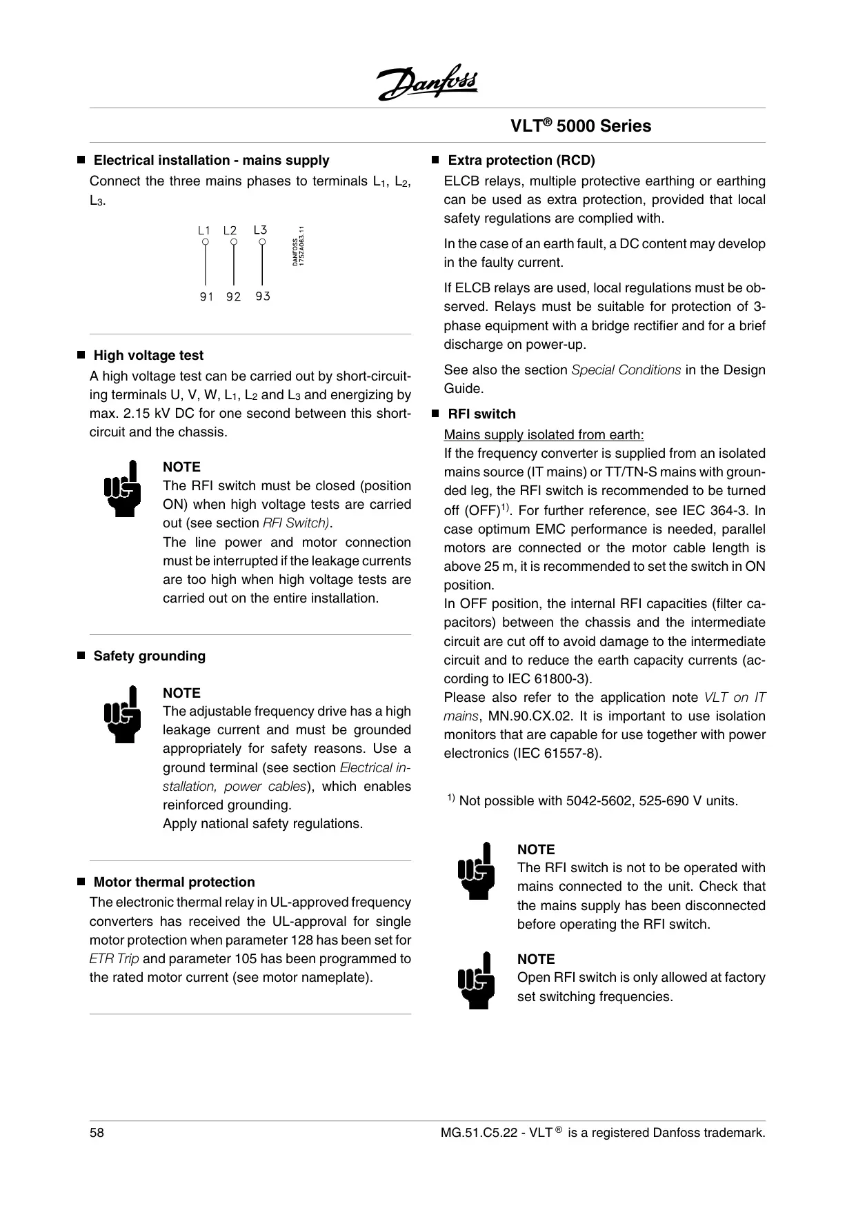
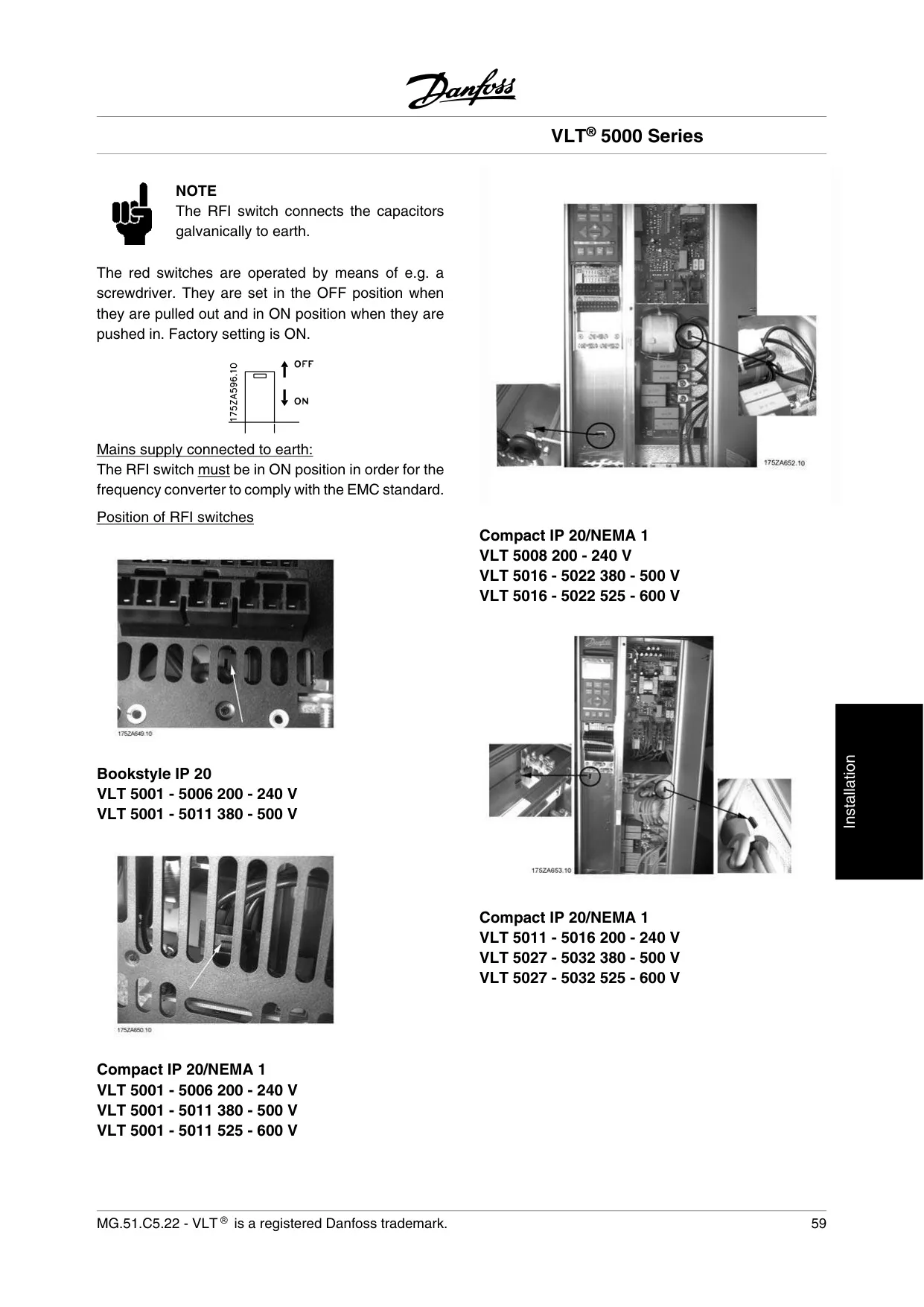
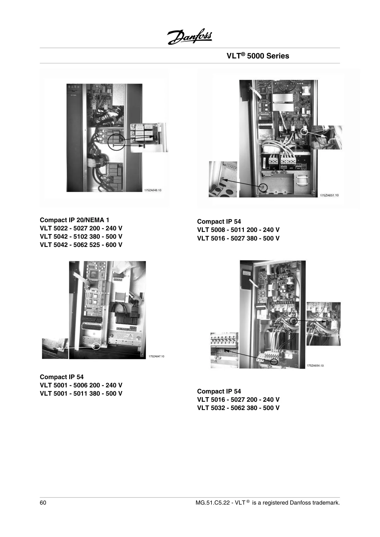
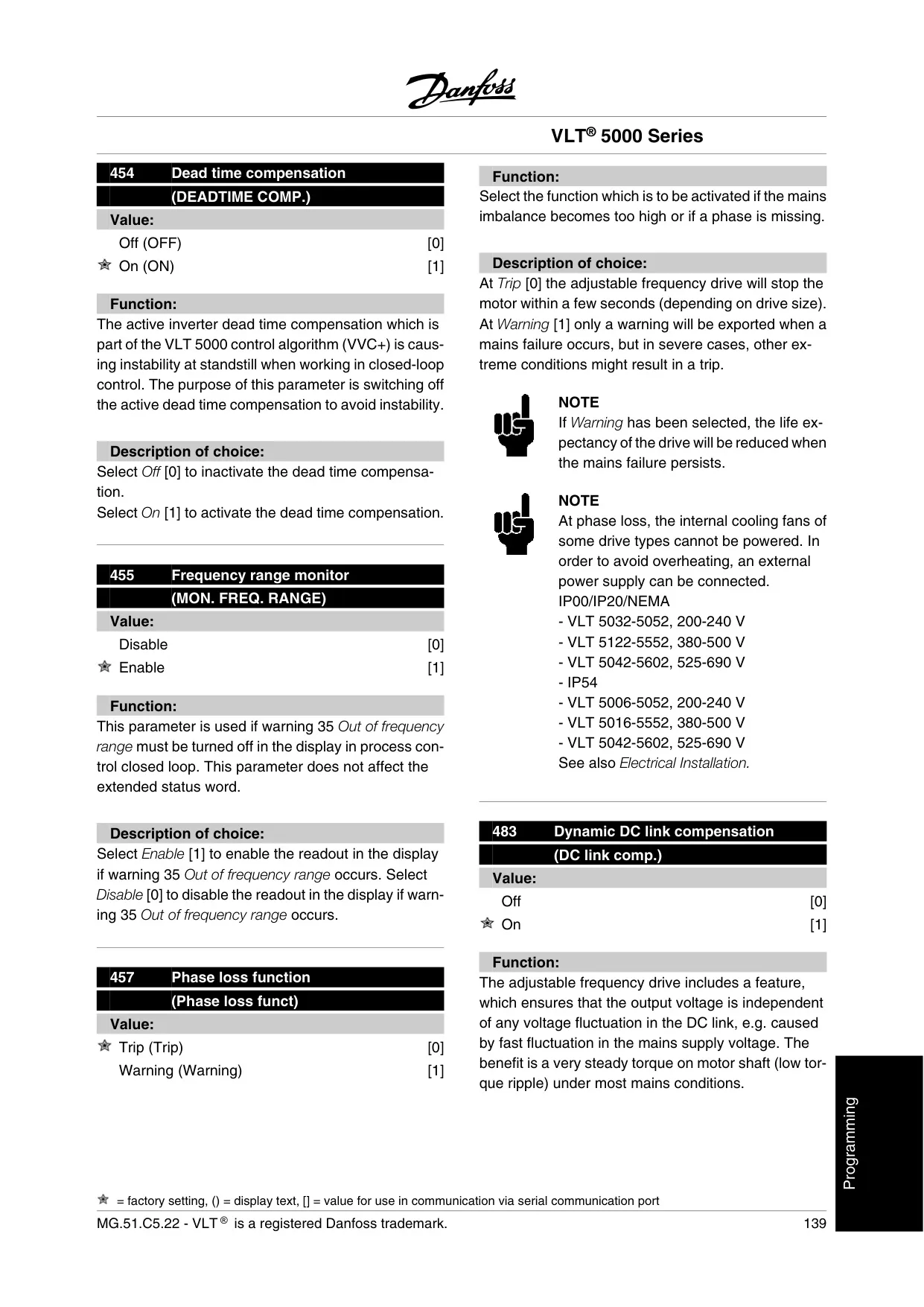
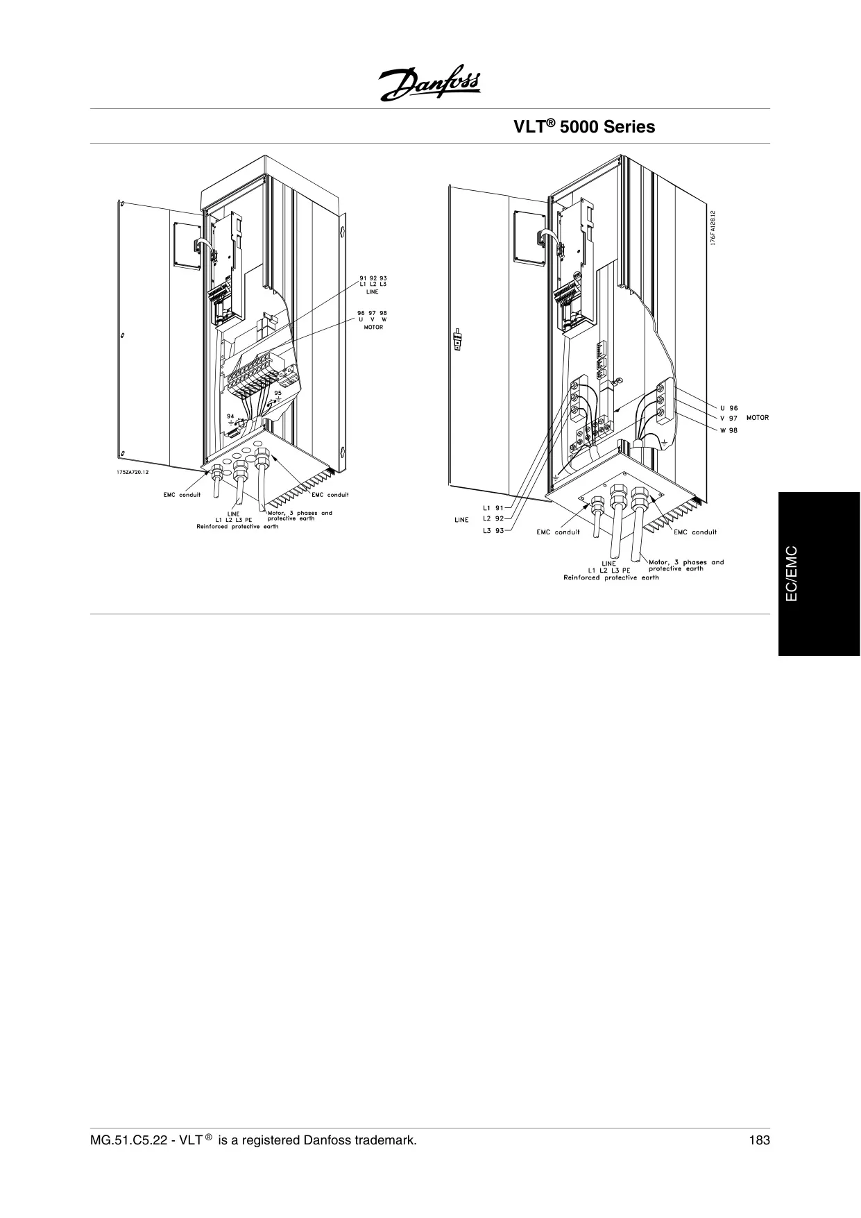
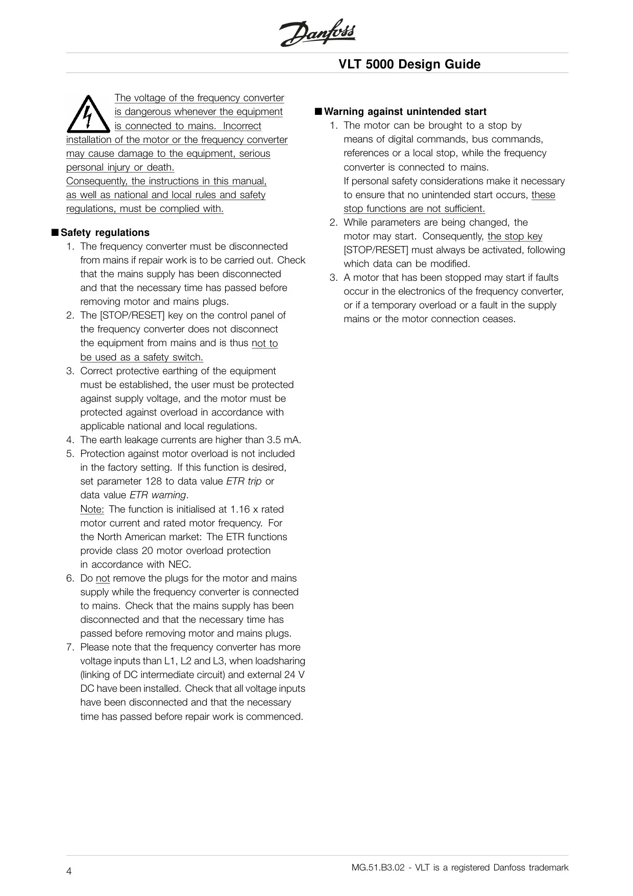
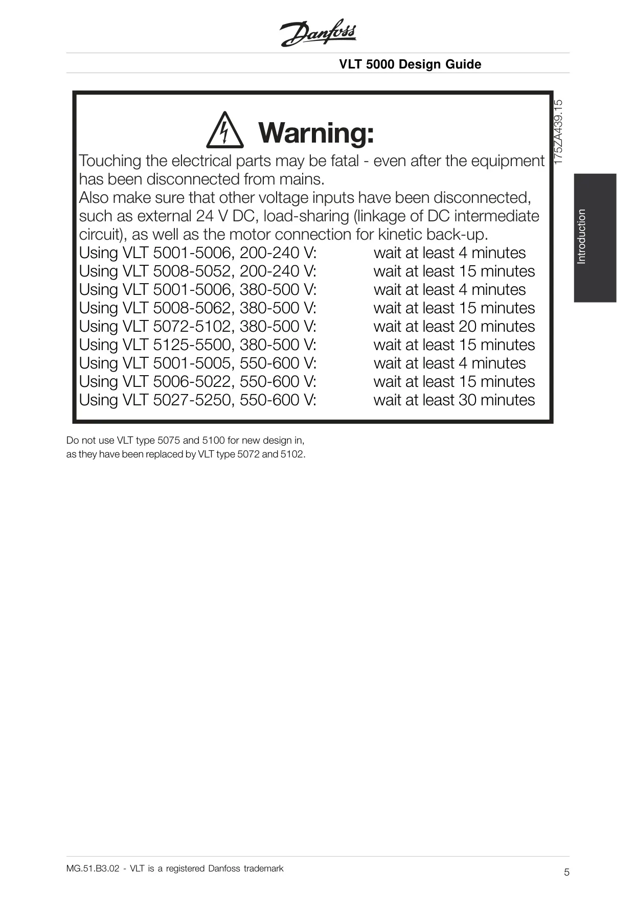
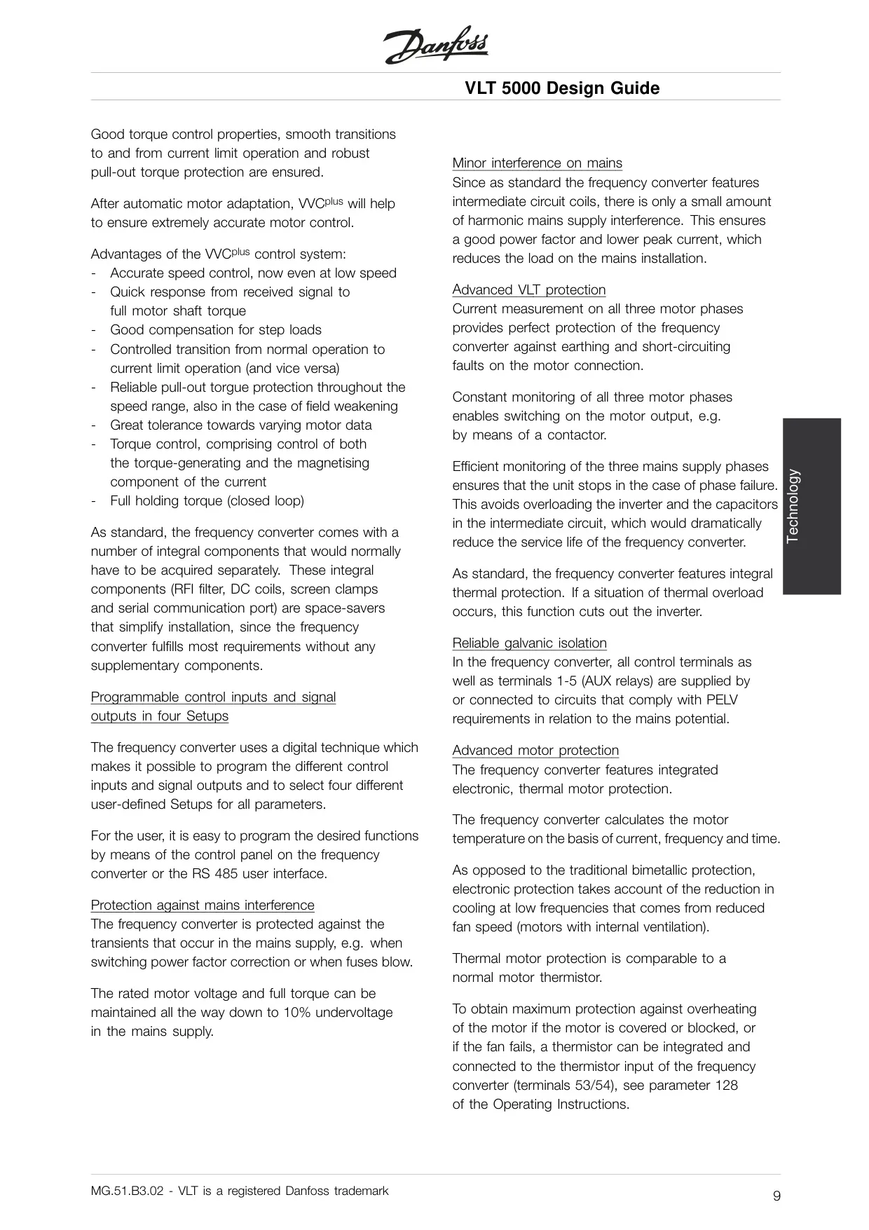
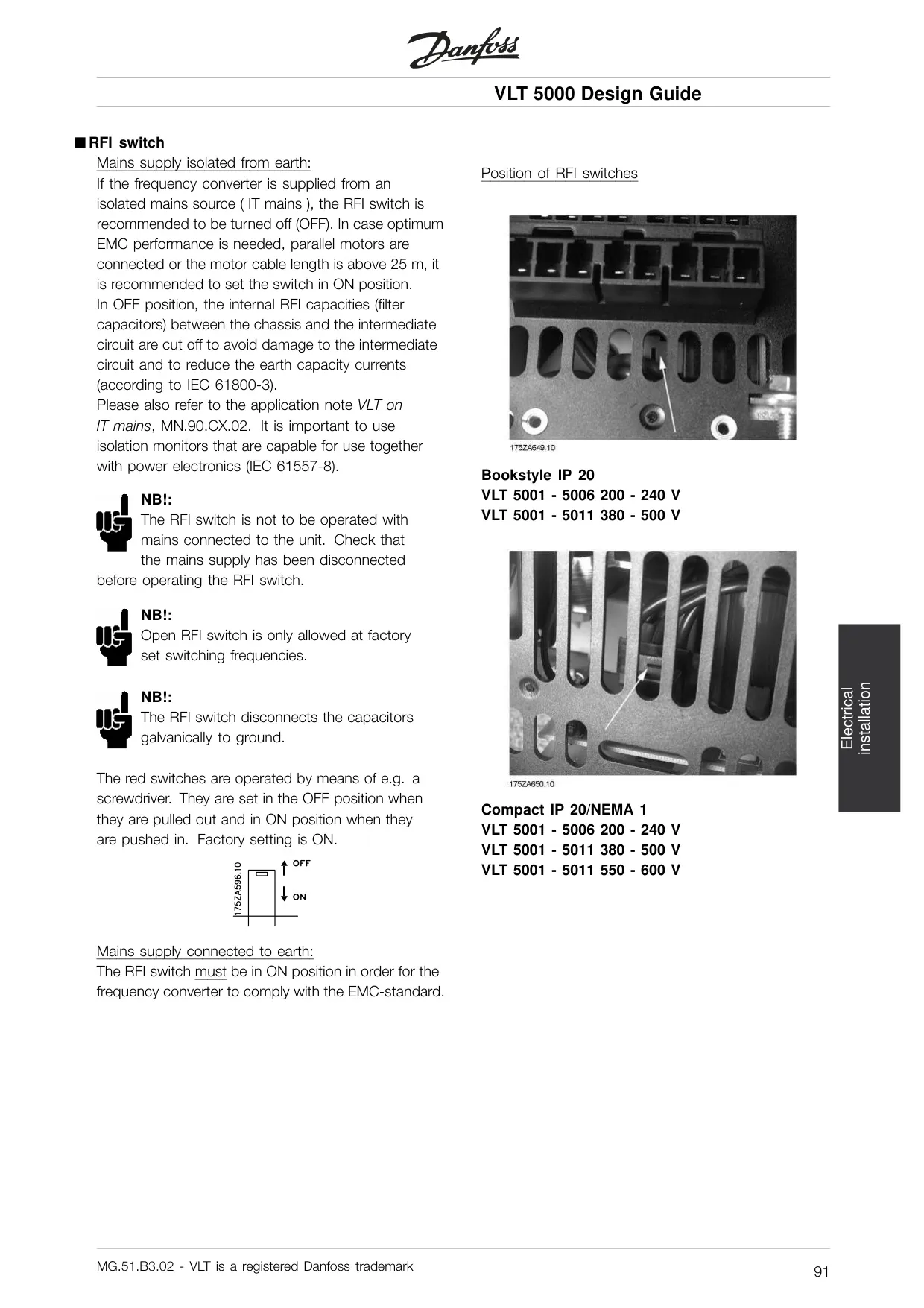
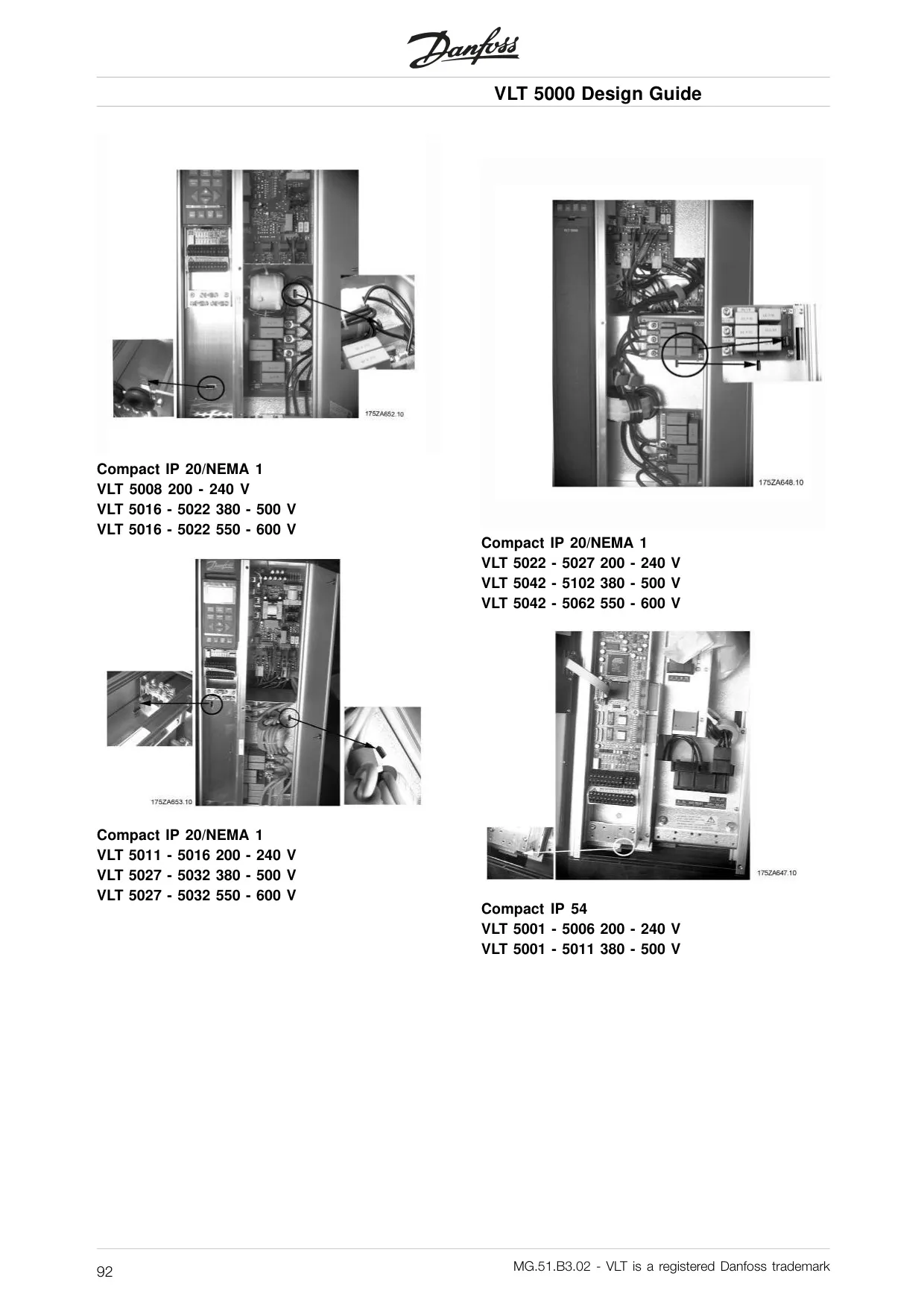
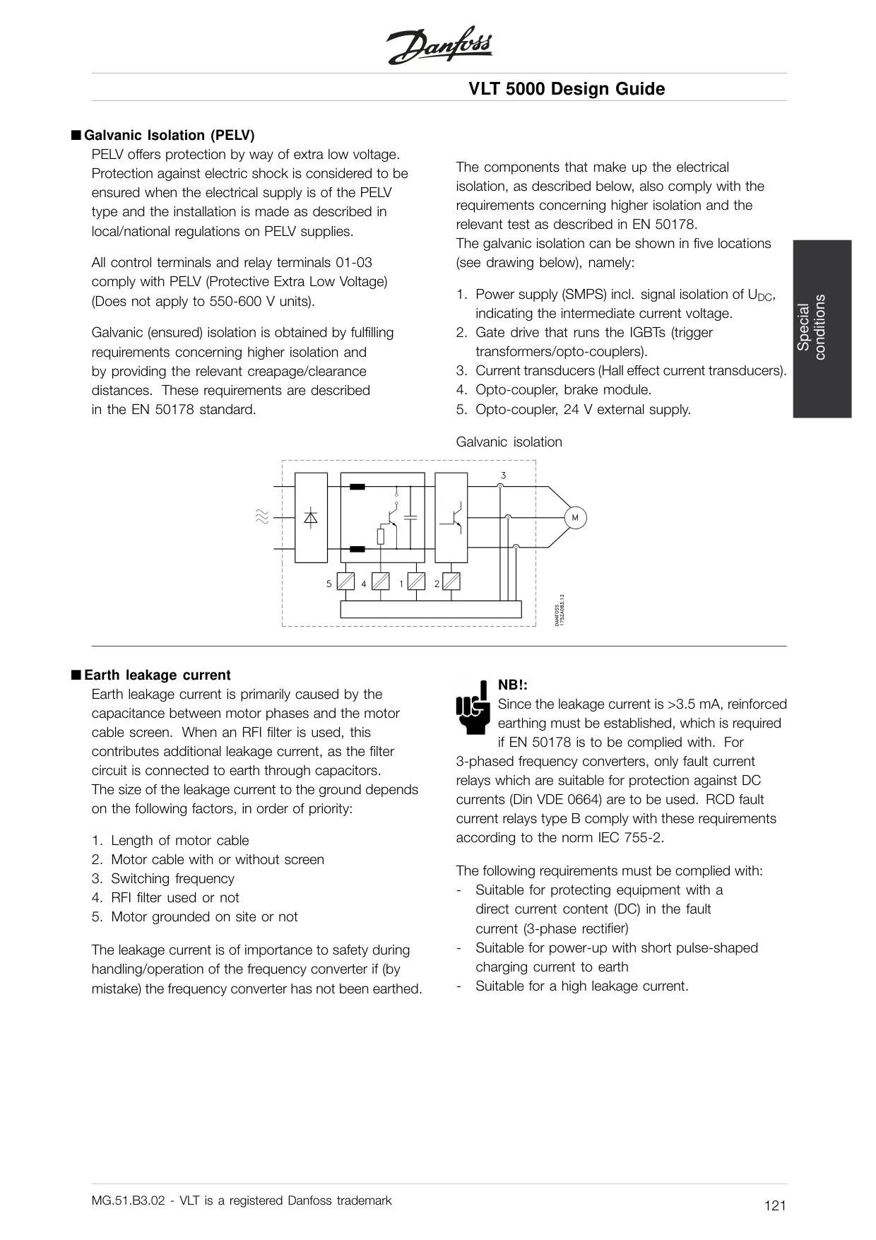
Safety is paramount, with built-in protection features including electronic motor thermal protection, short-circuit, and earth fault safeguards on motor terminals. The drive also monitors intermediate circuit voltage and motor phase presence, providing warnings or alarms for potential issues. The RFI switch allows adaptation for isolated AC line supplies, and proper grounding is reinforced for safety.
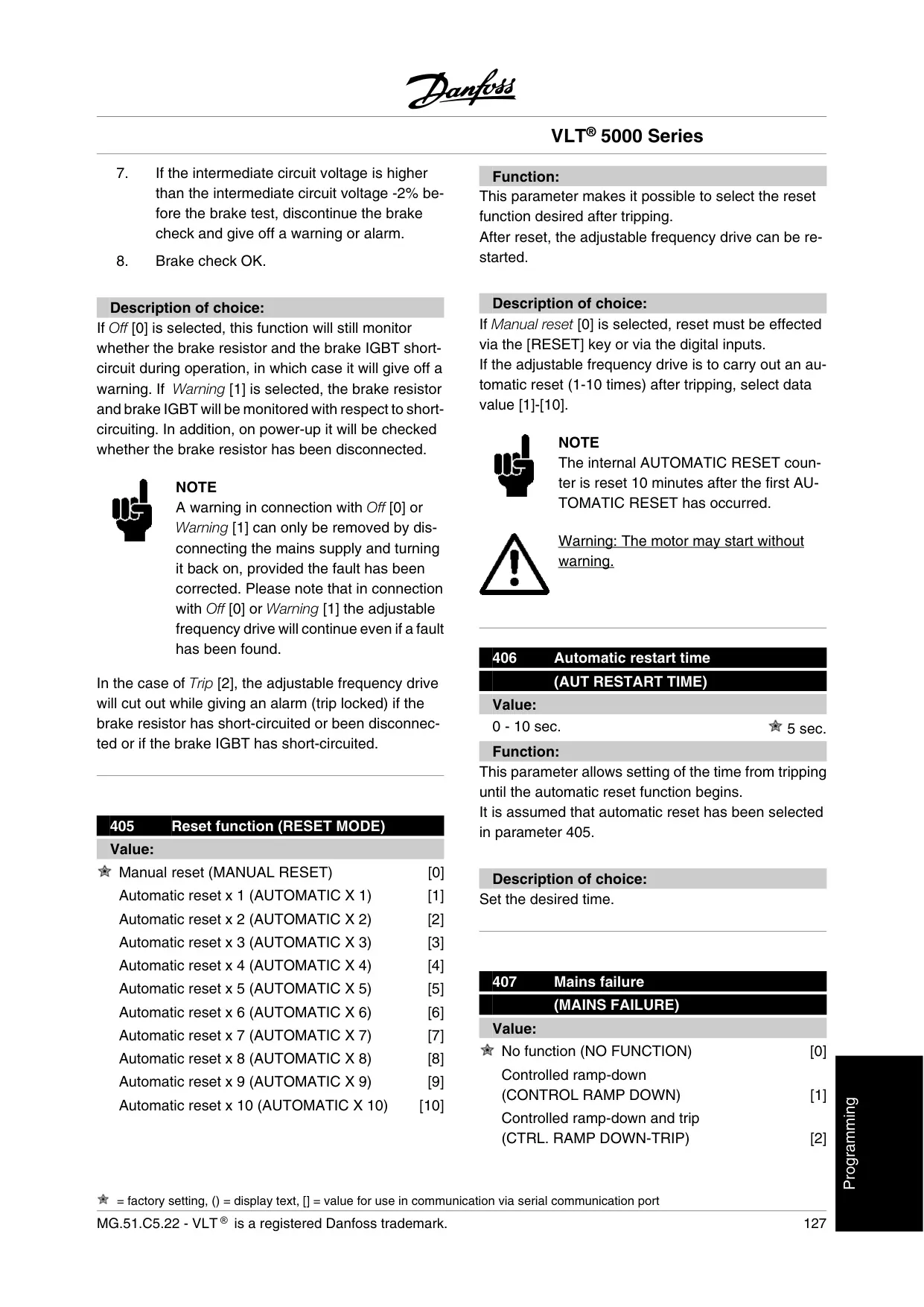
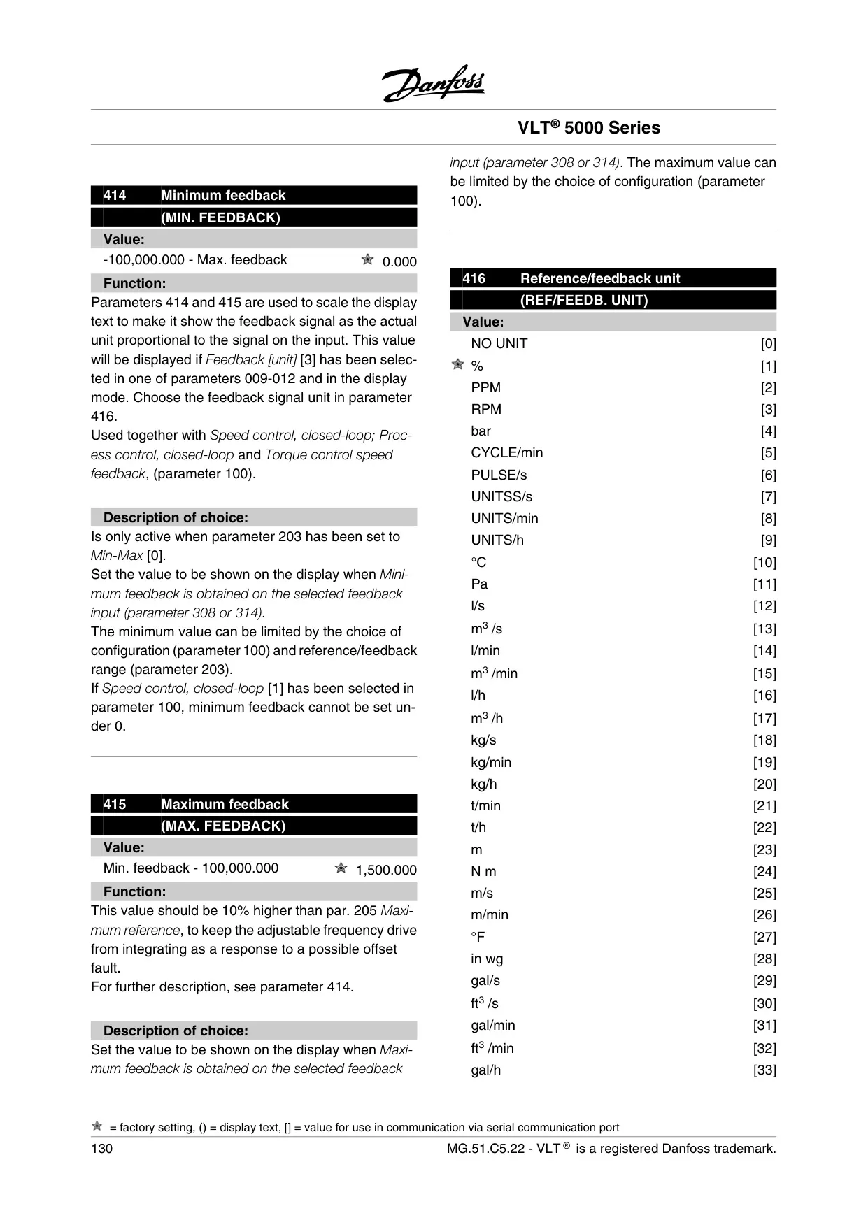
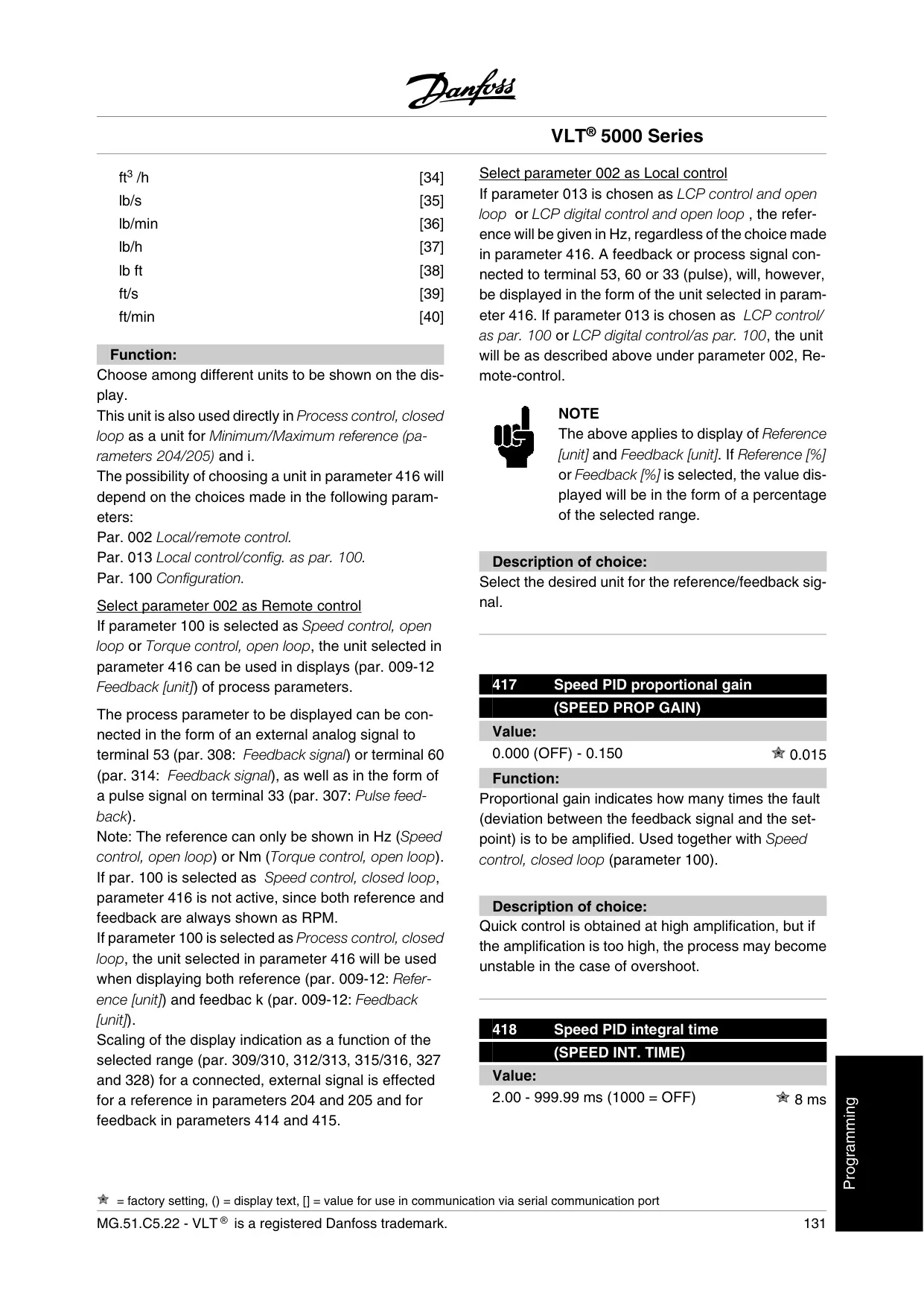
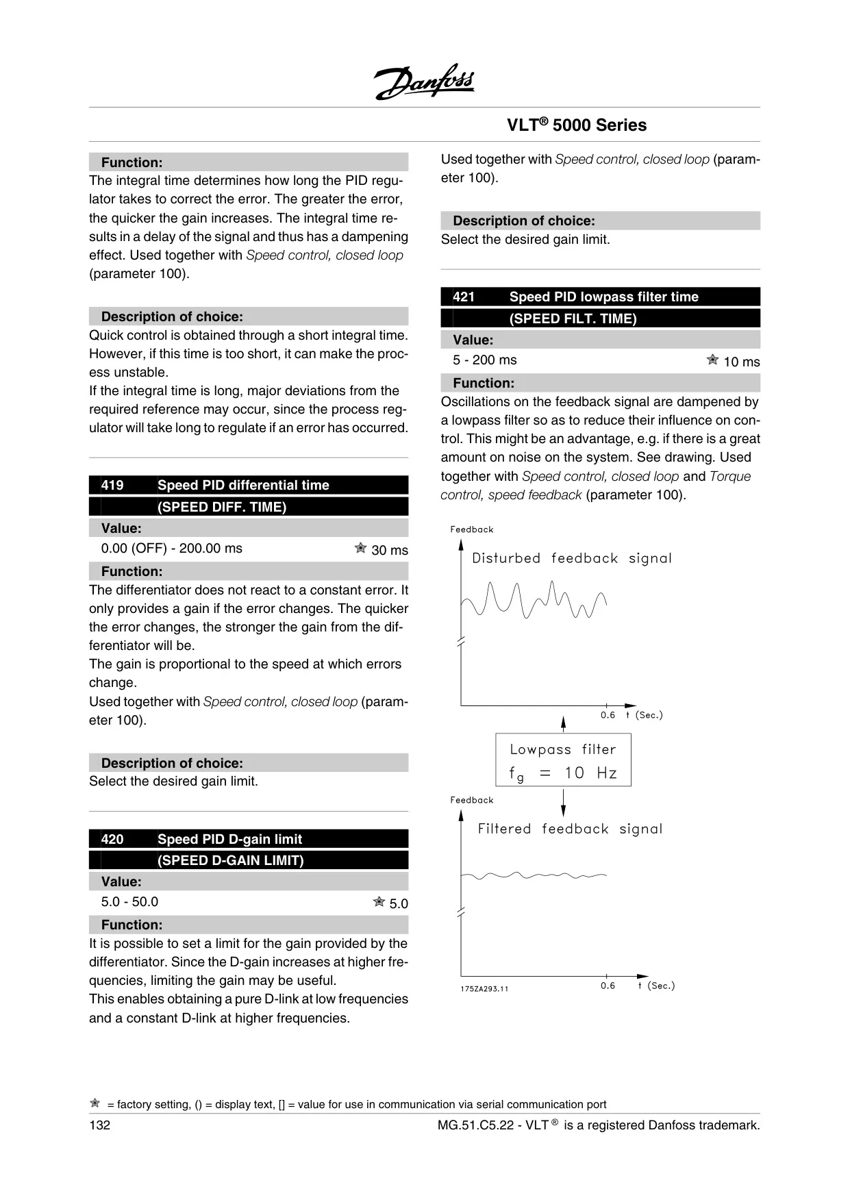
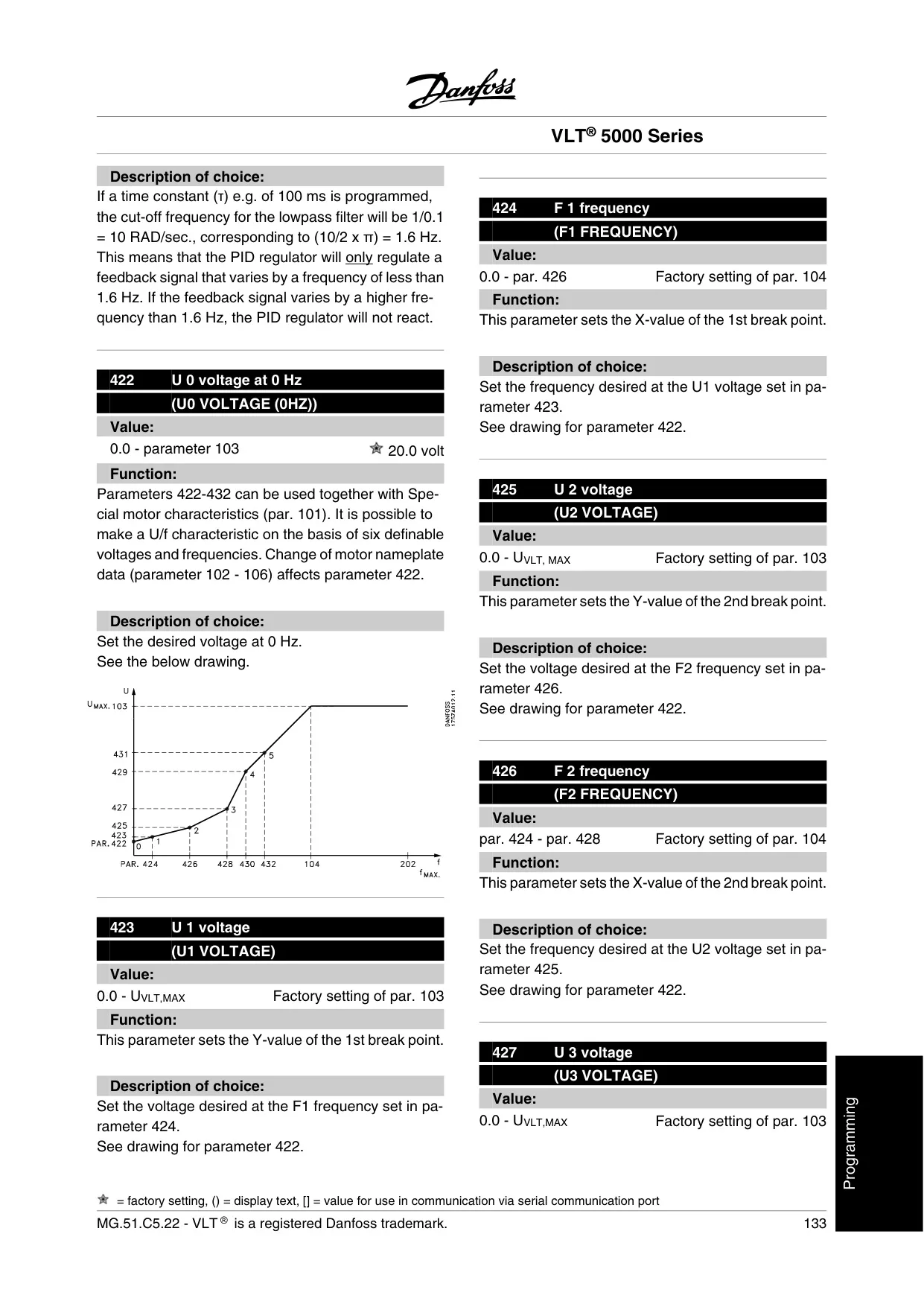
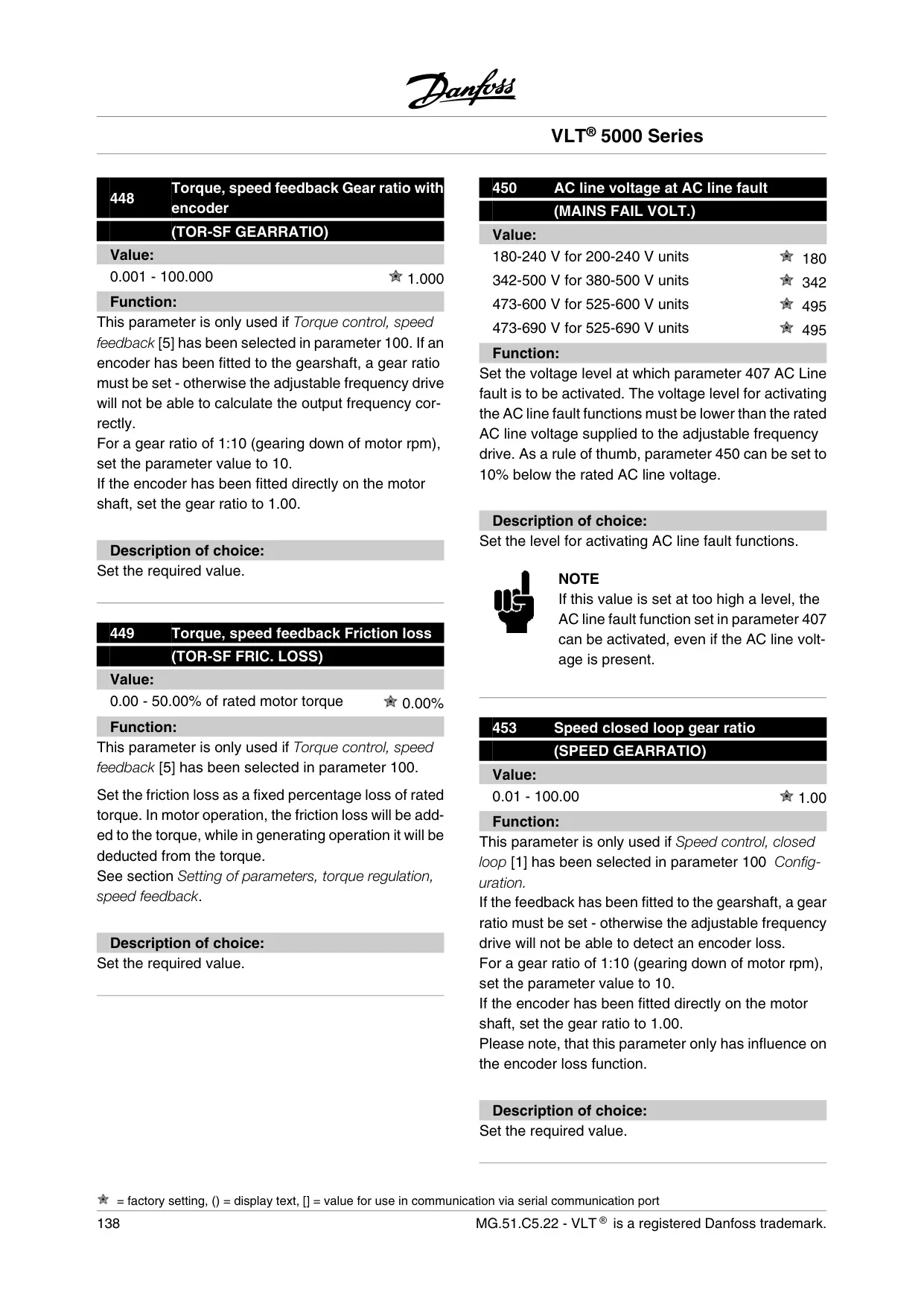
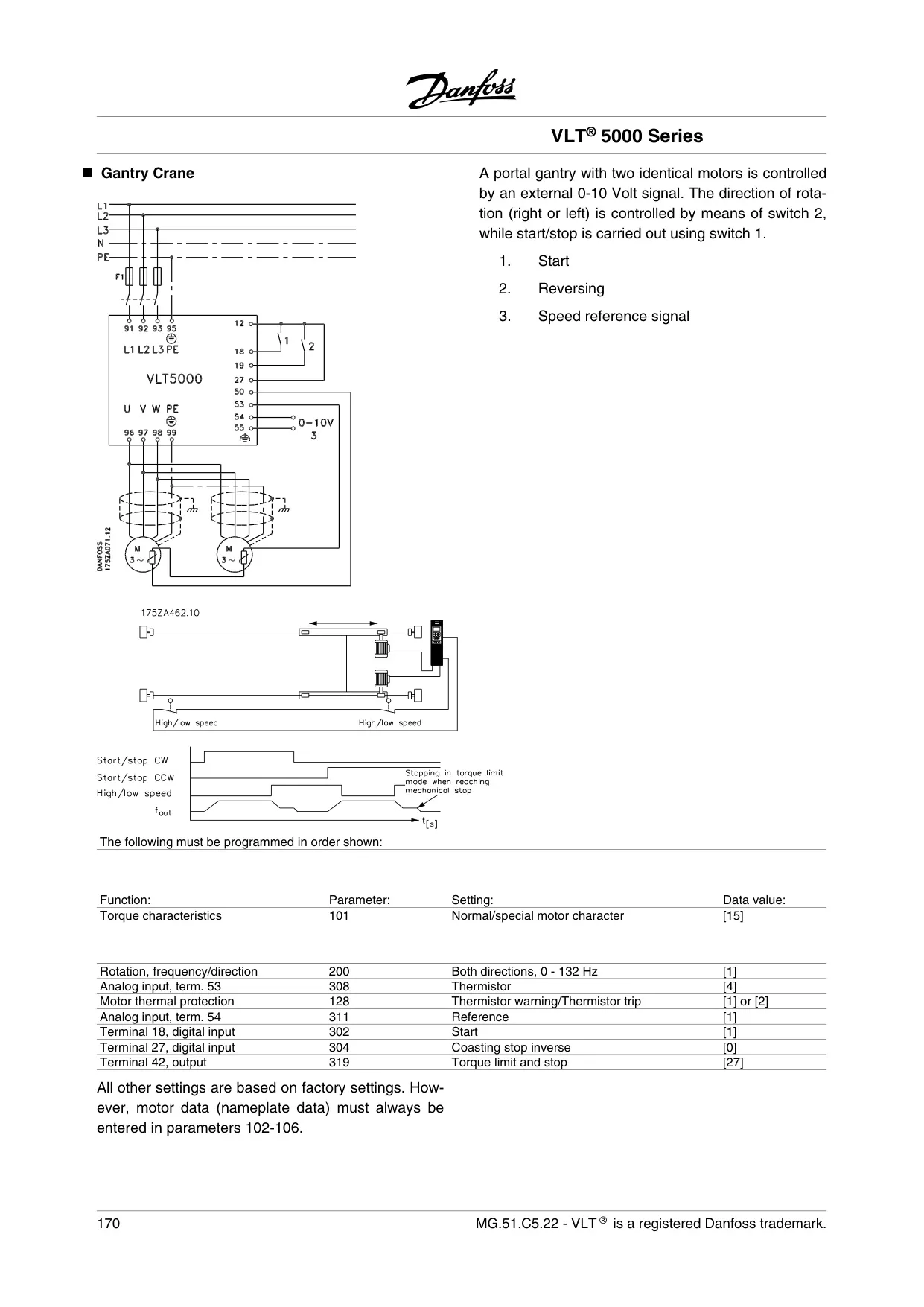
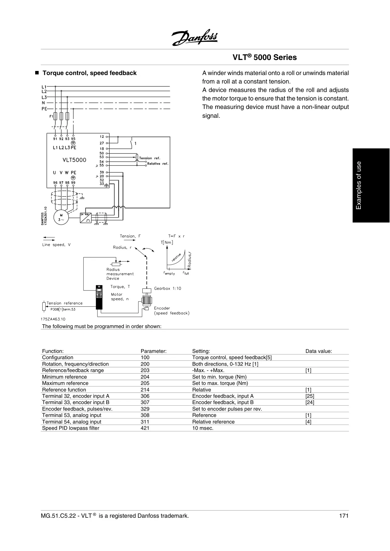
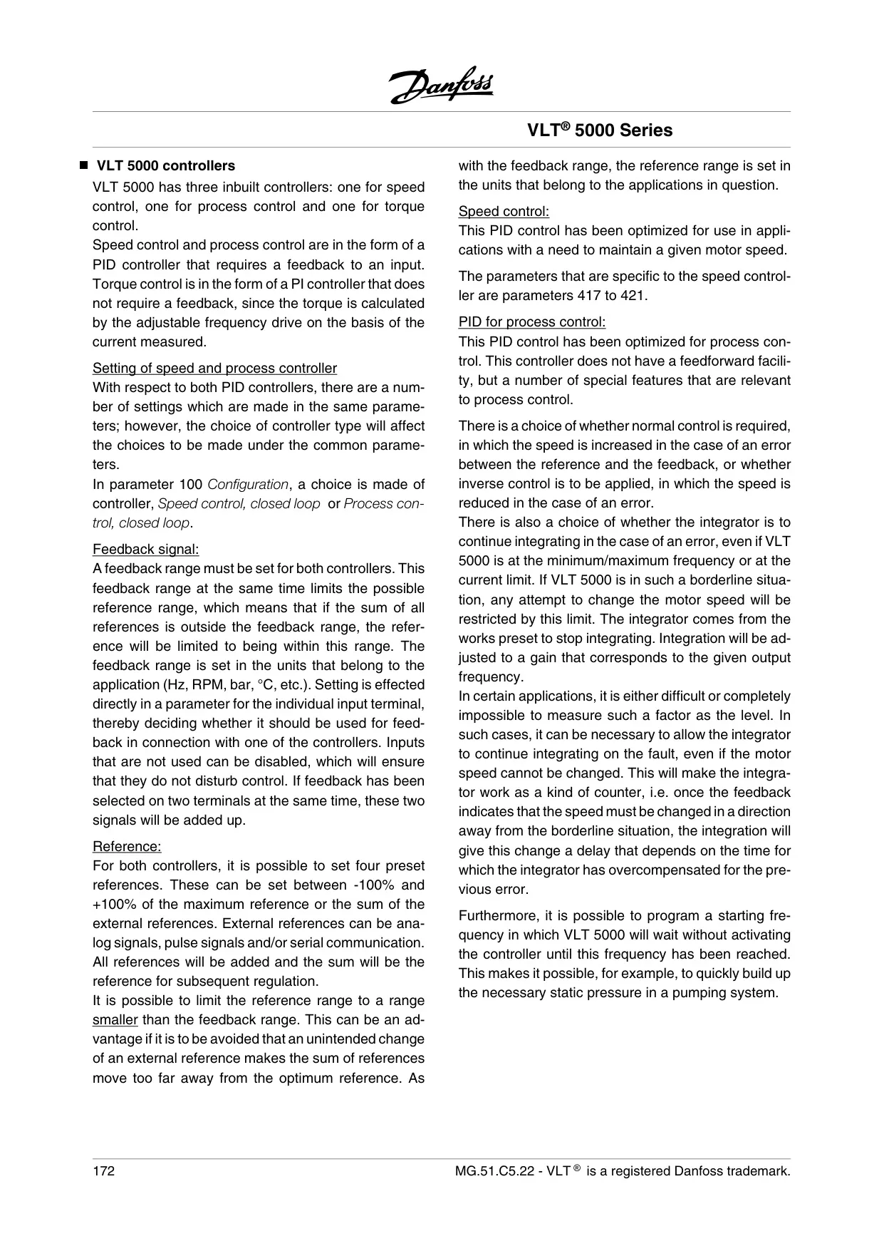
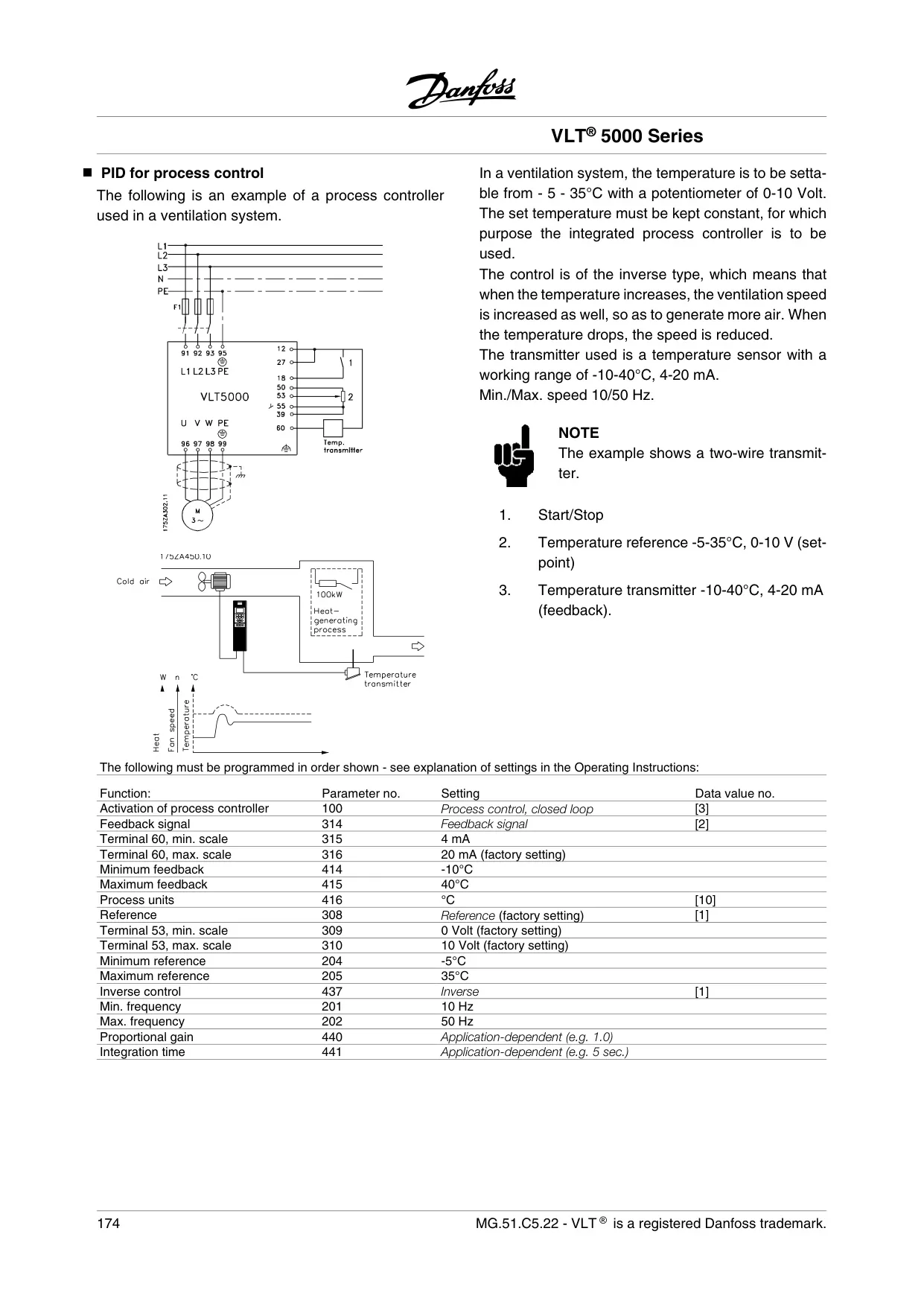
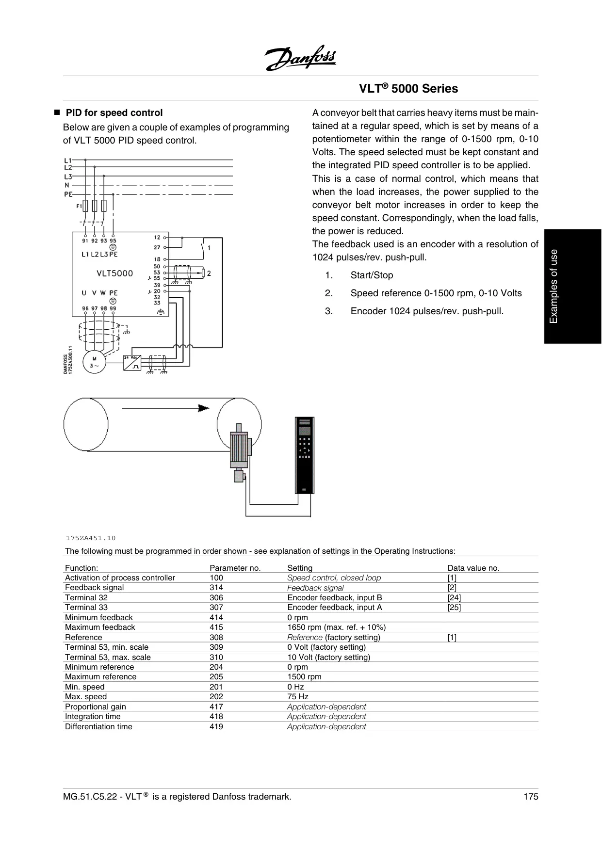
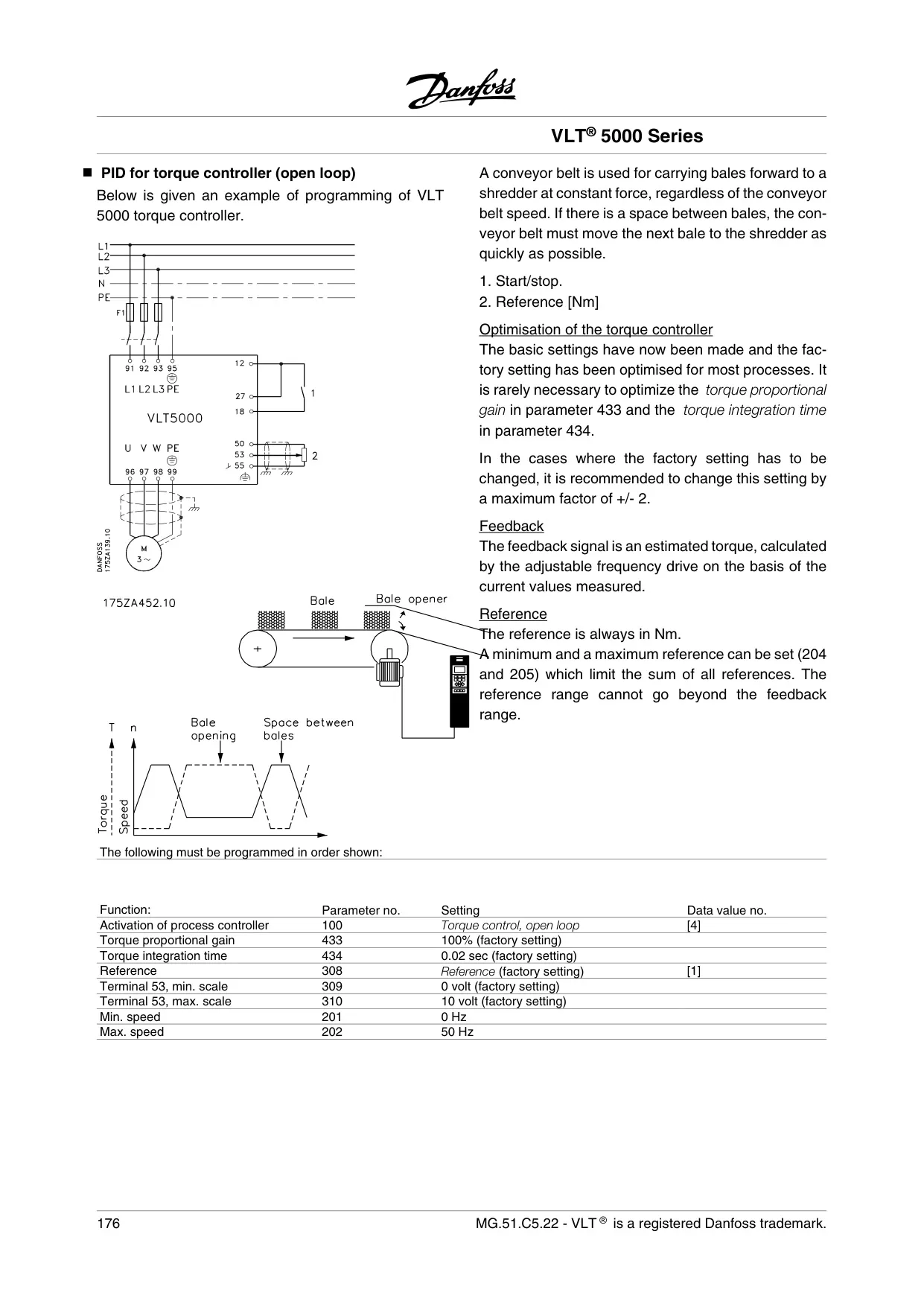
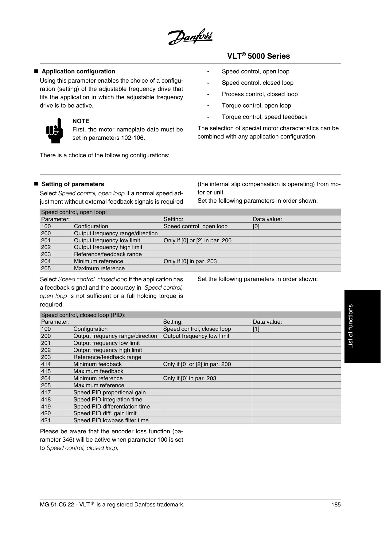
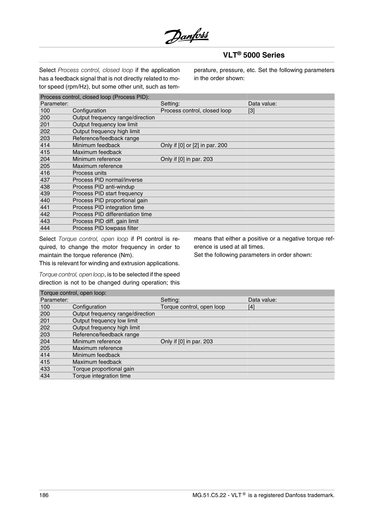
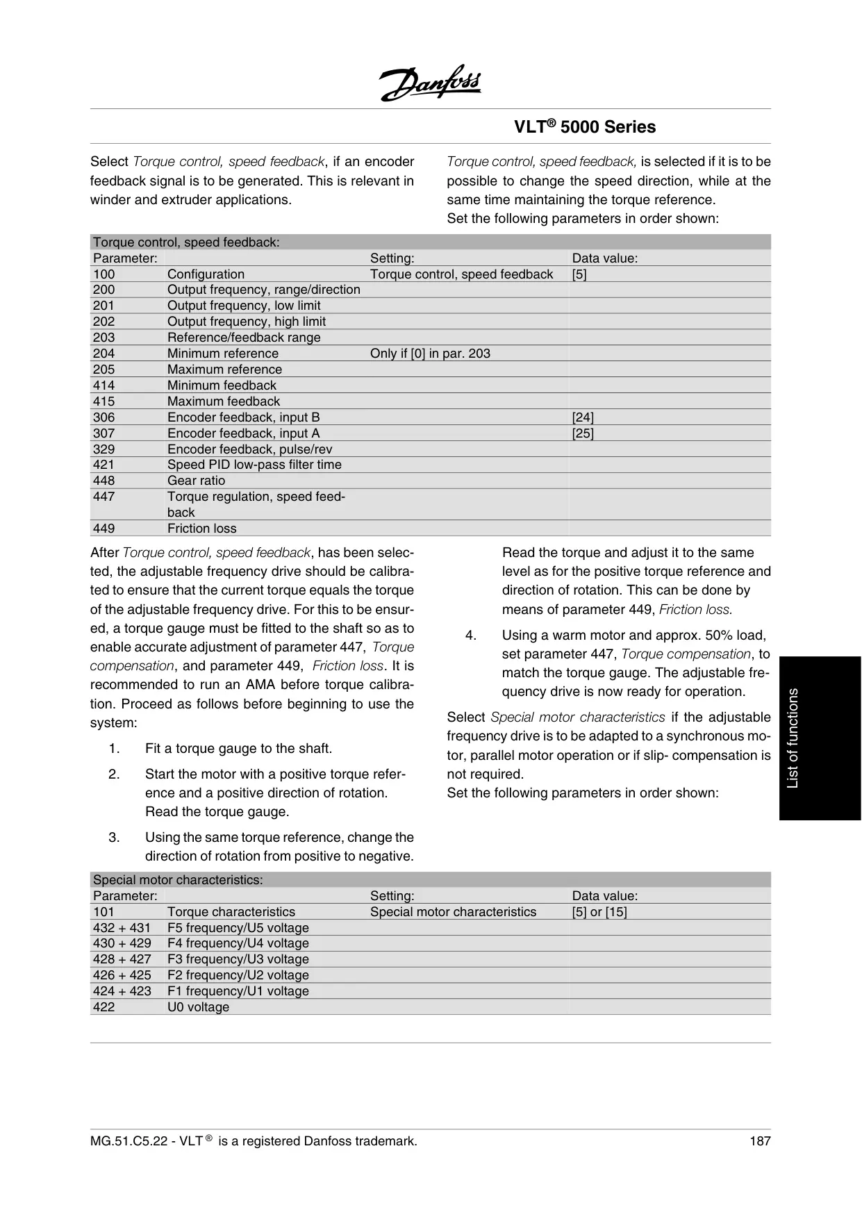
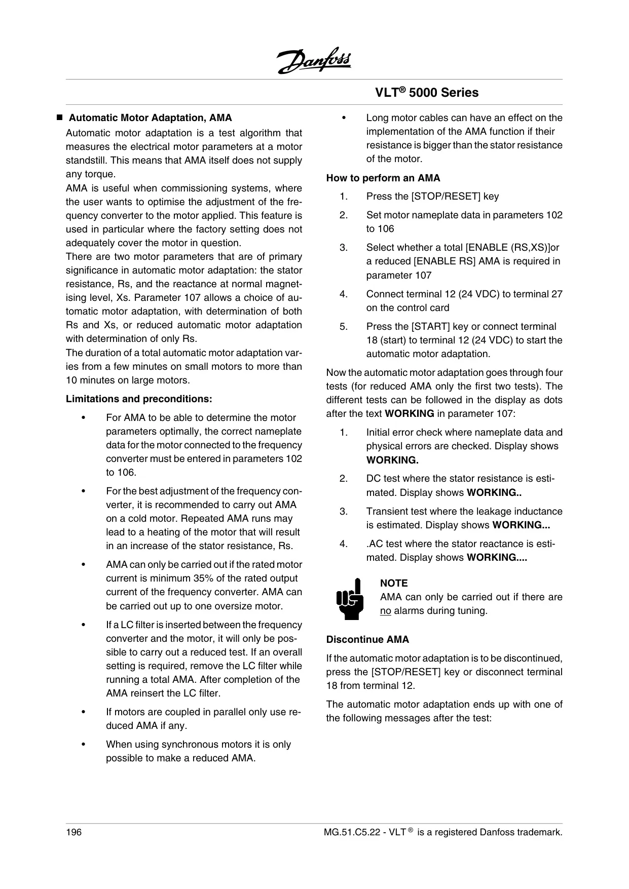
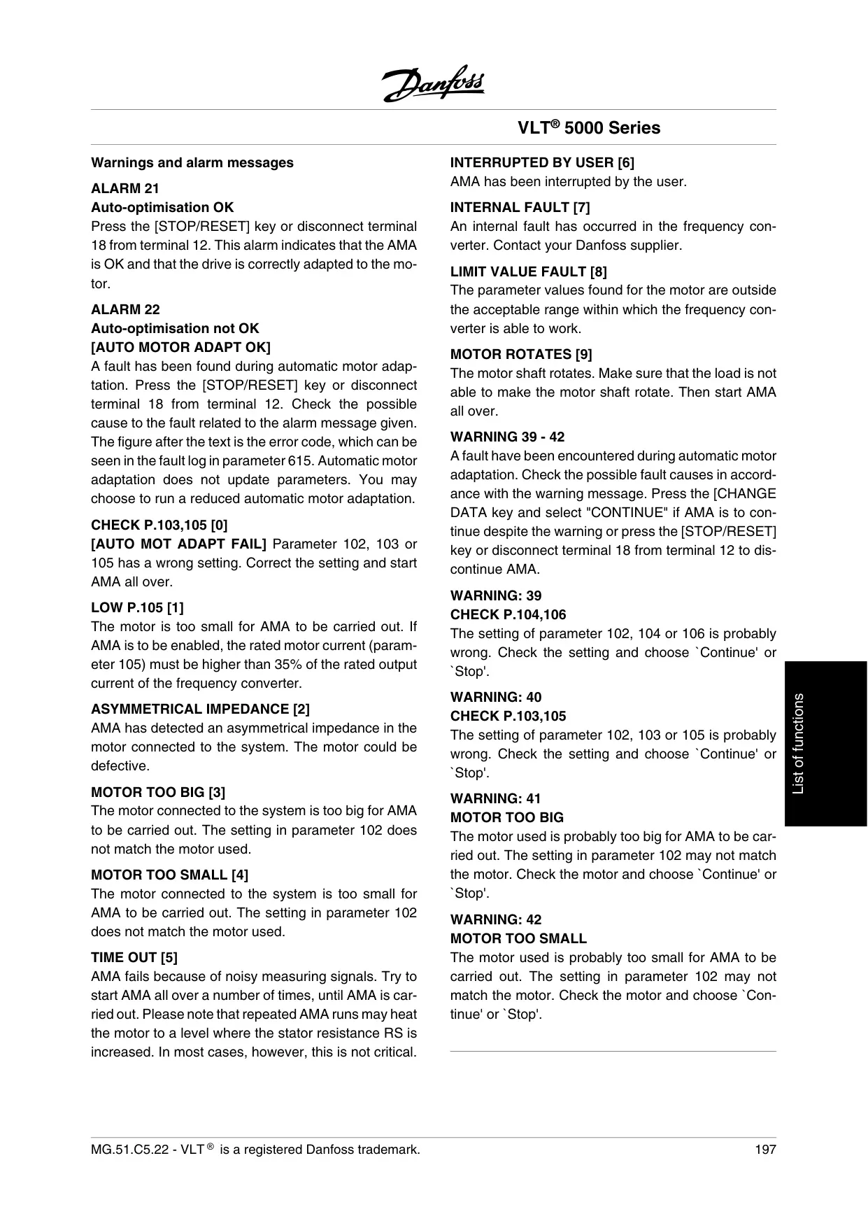
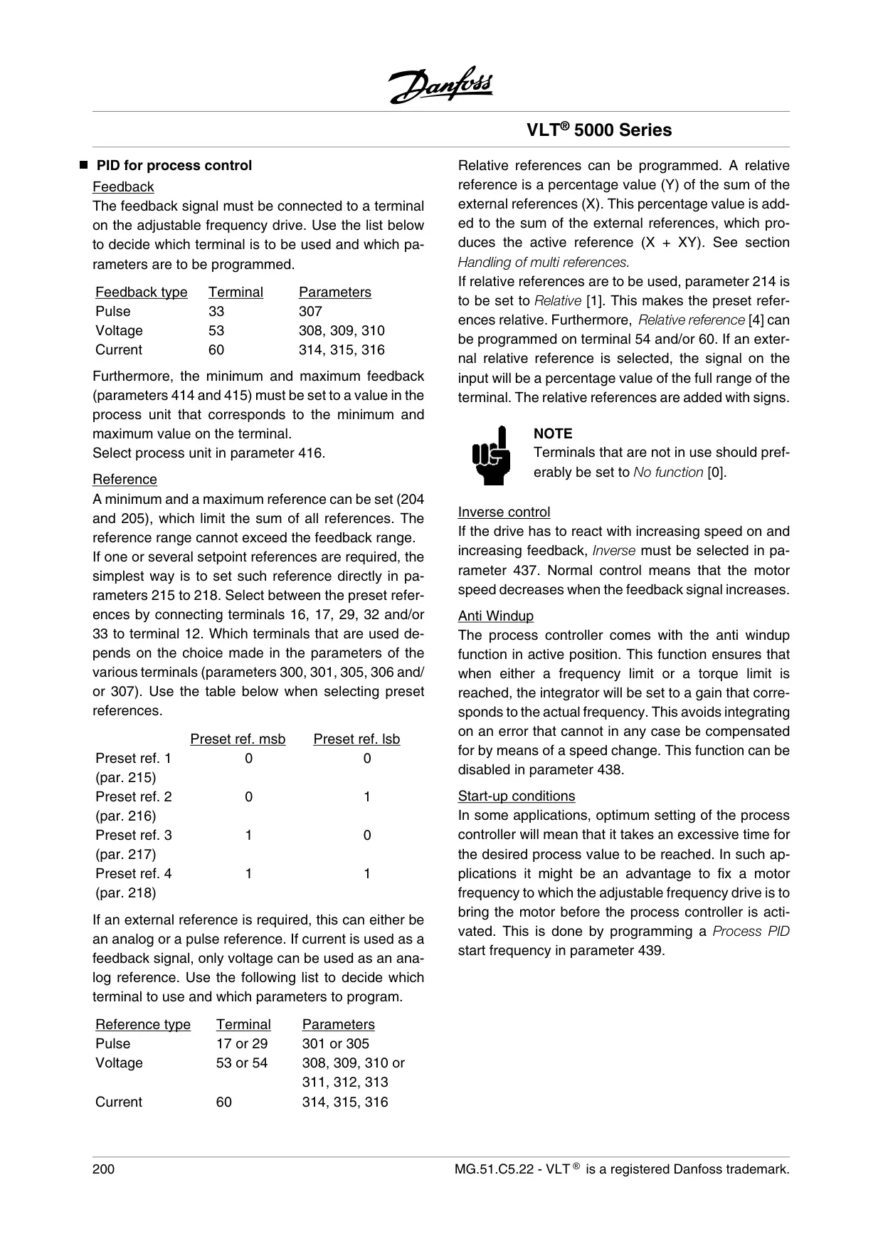
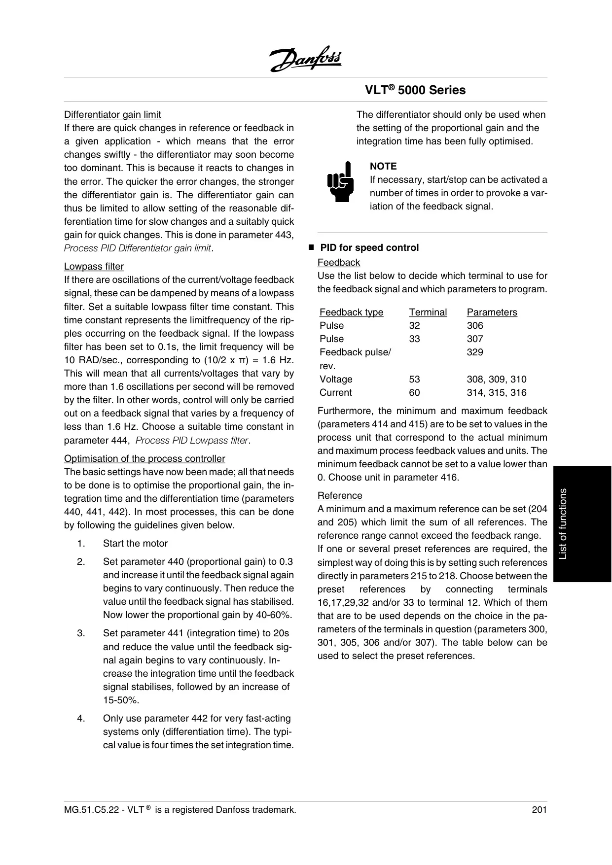
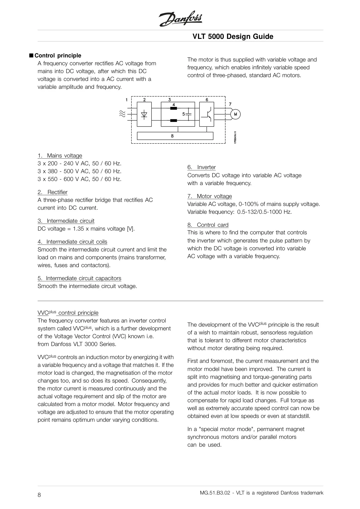
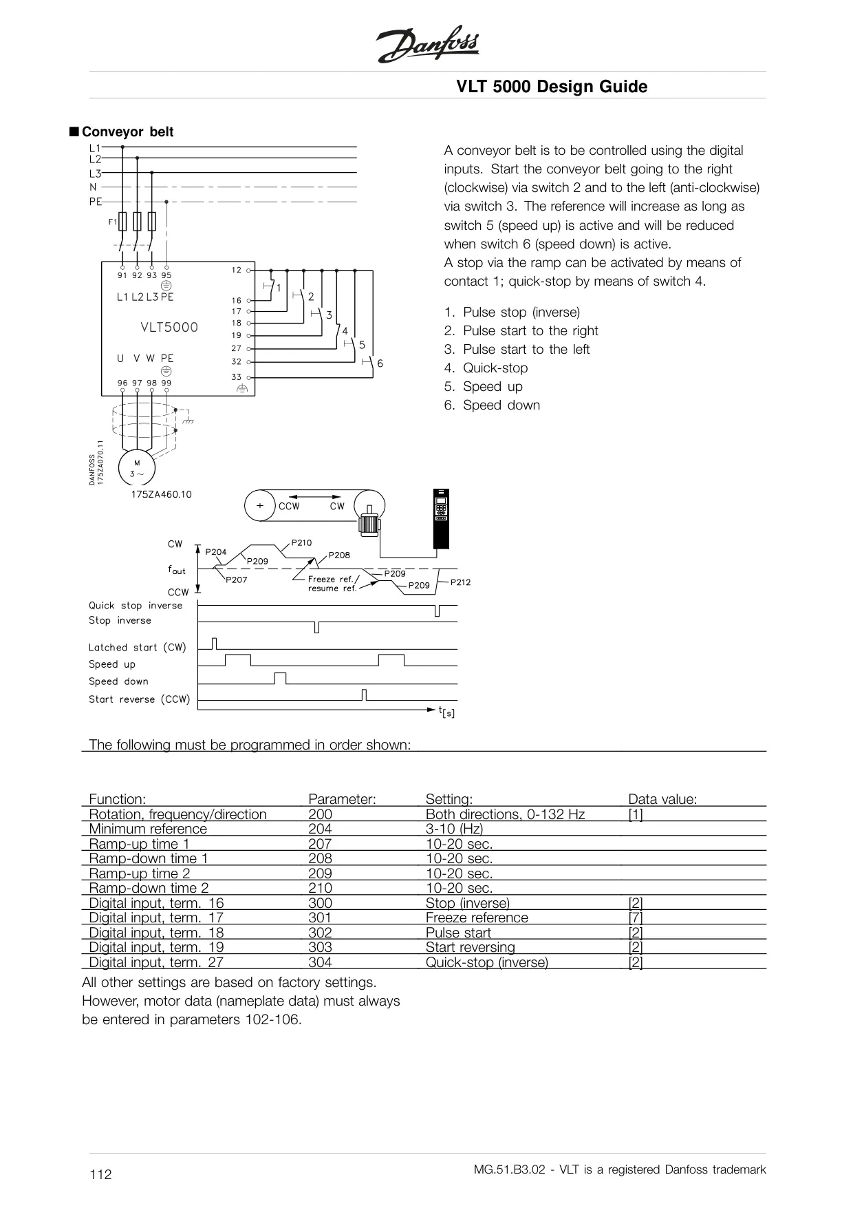
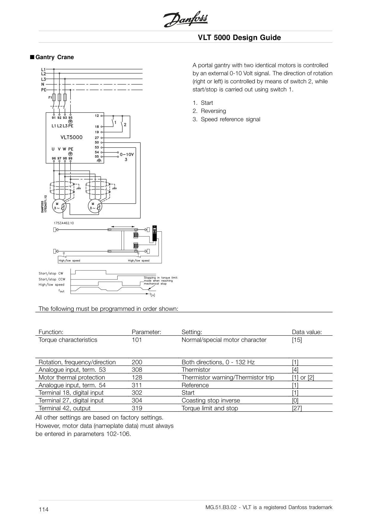
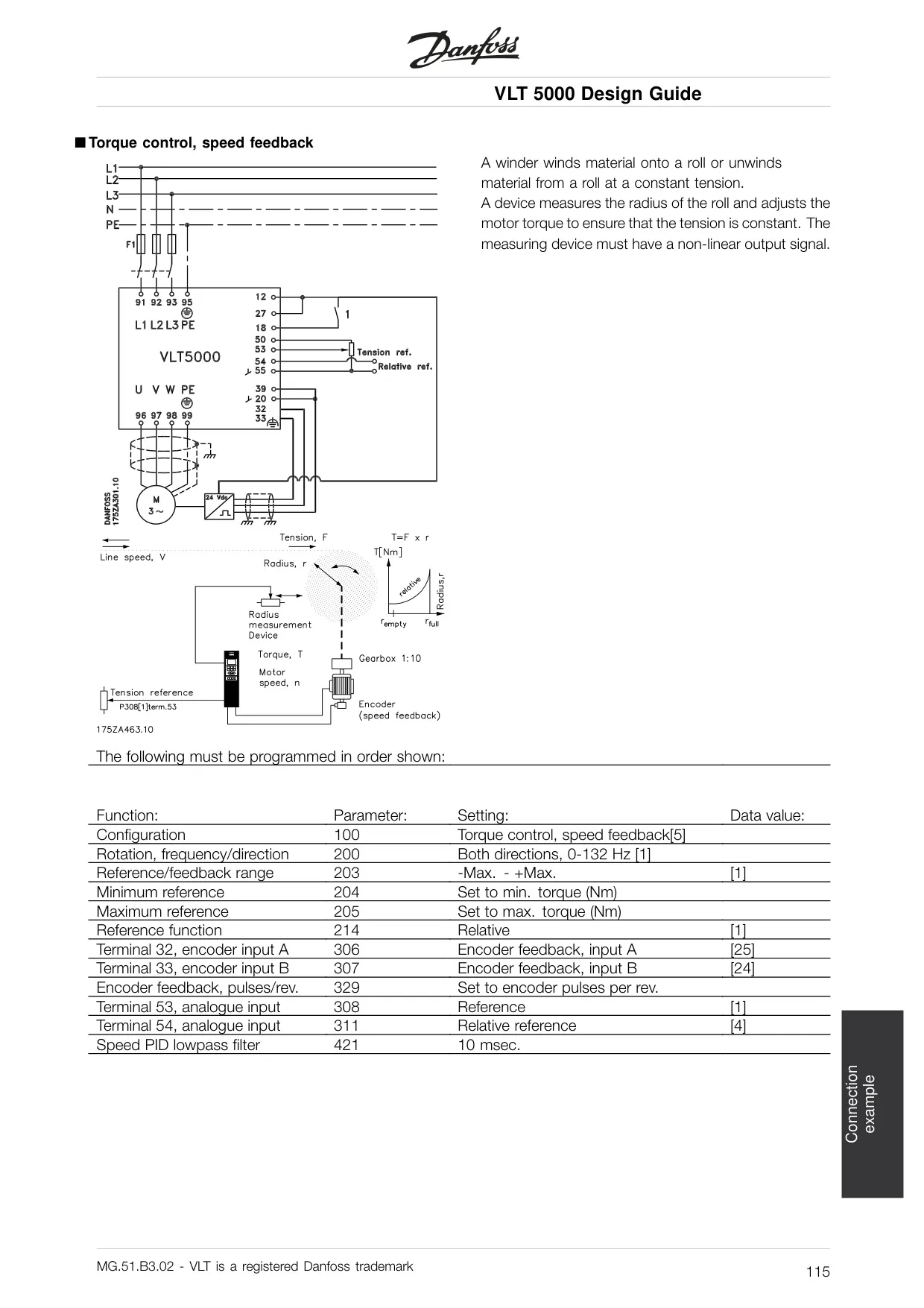
Advanced control functionalities include configurable application settings such as Speed Control (Open/Closed Loop), Process Control (Closed Loop), and Torque Control (Open Loop/Speed Feedback). These options allow precise adaptation to diverse applications like conveyor belts, pumps, and gantry cranes. An important feature is Automatic Motor Adaptation (AMA), which automatically sets control parameters for optimal motor performance.
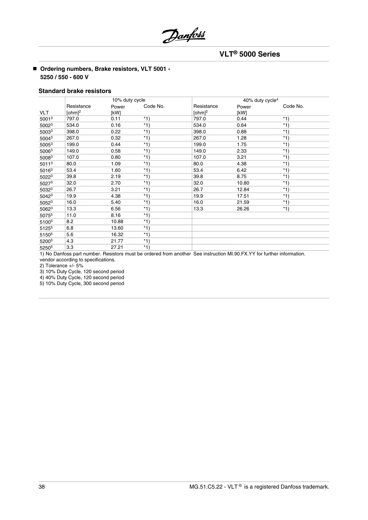
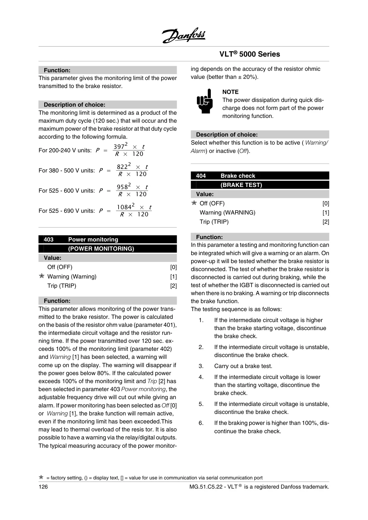
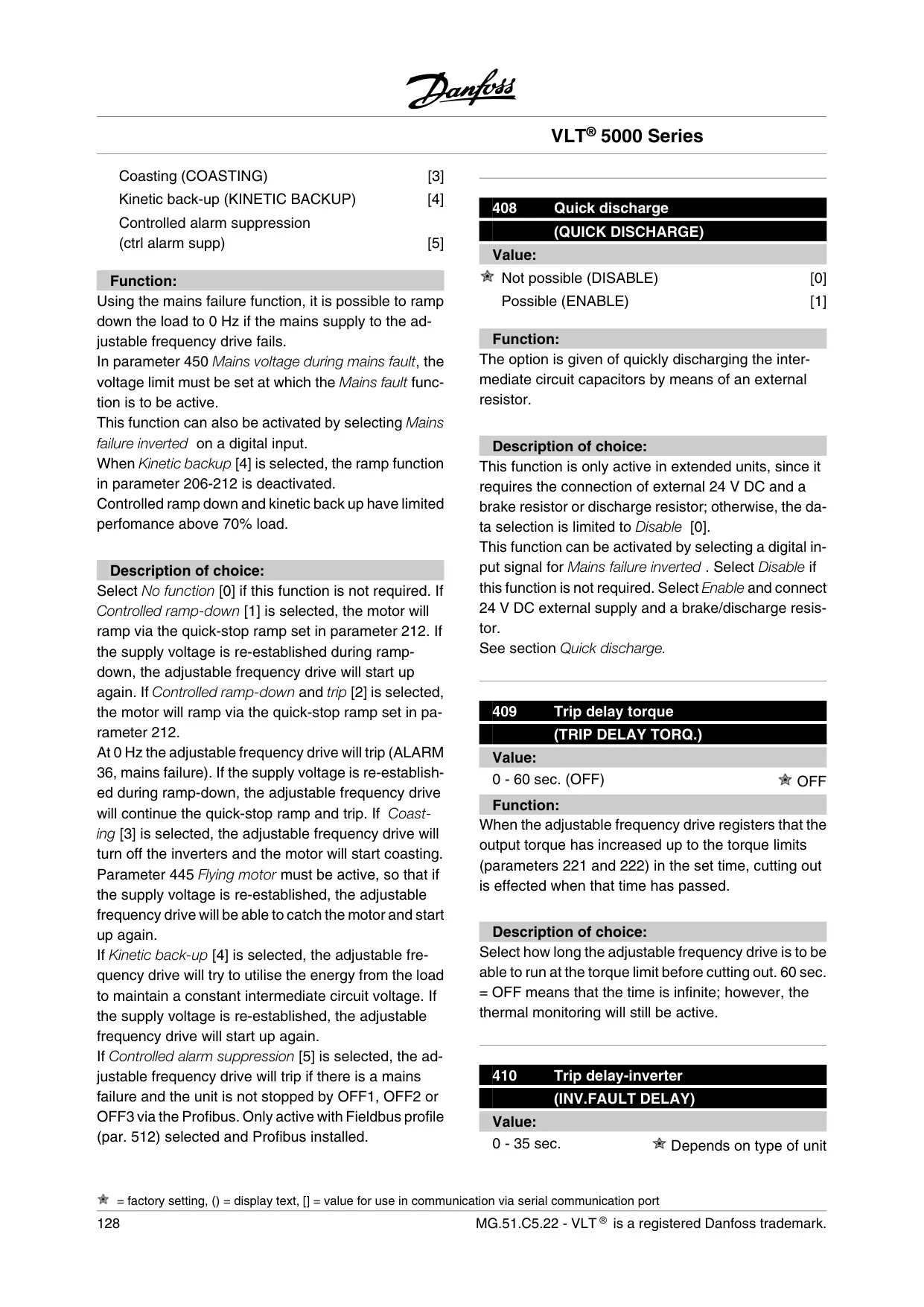
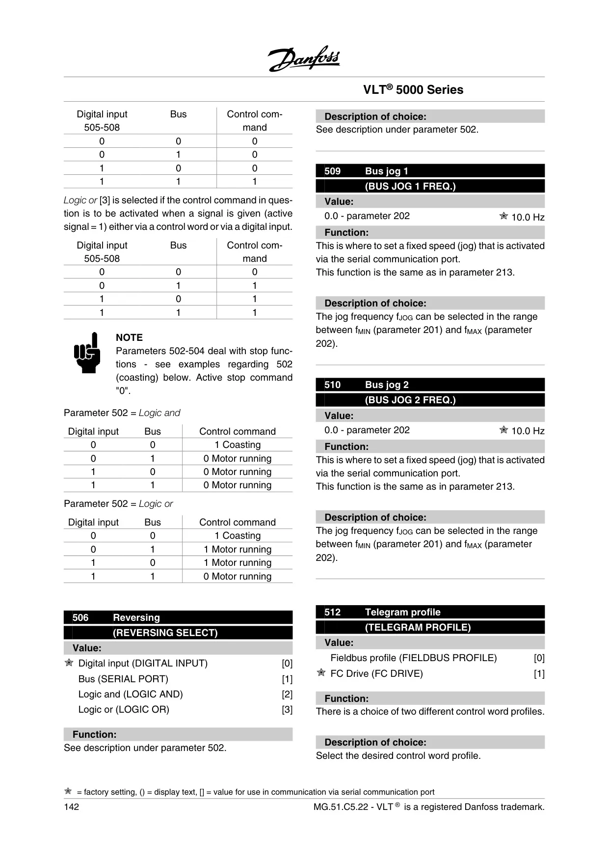
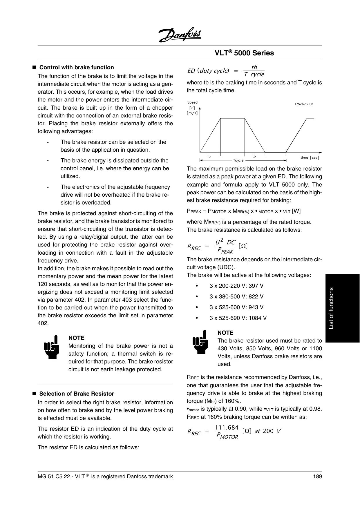
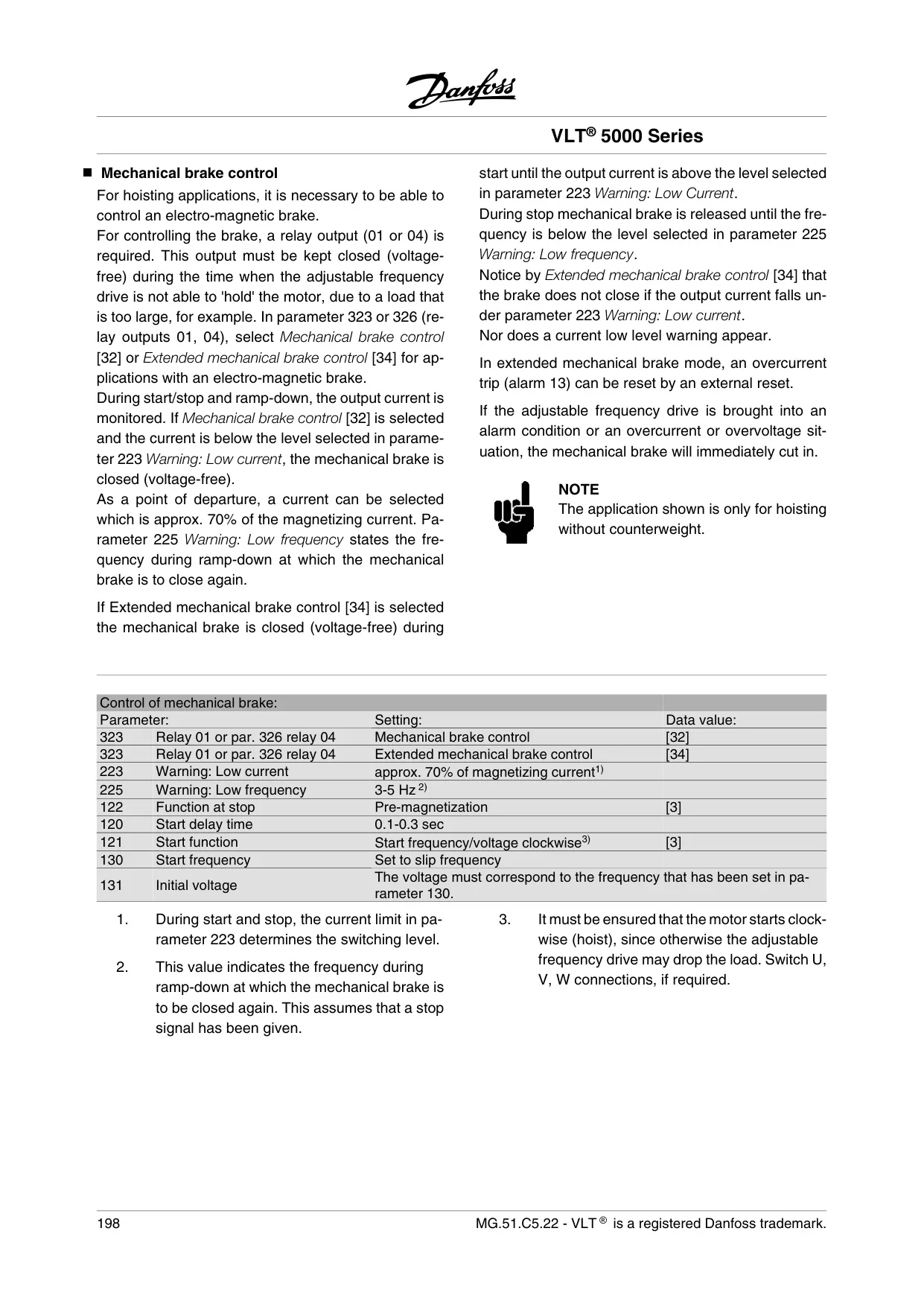
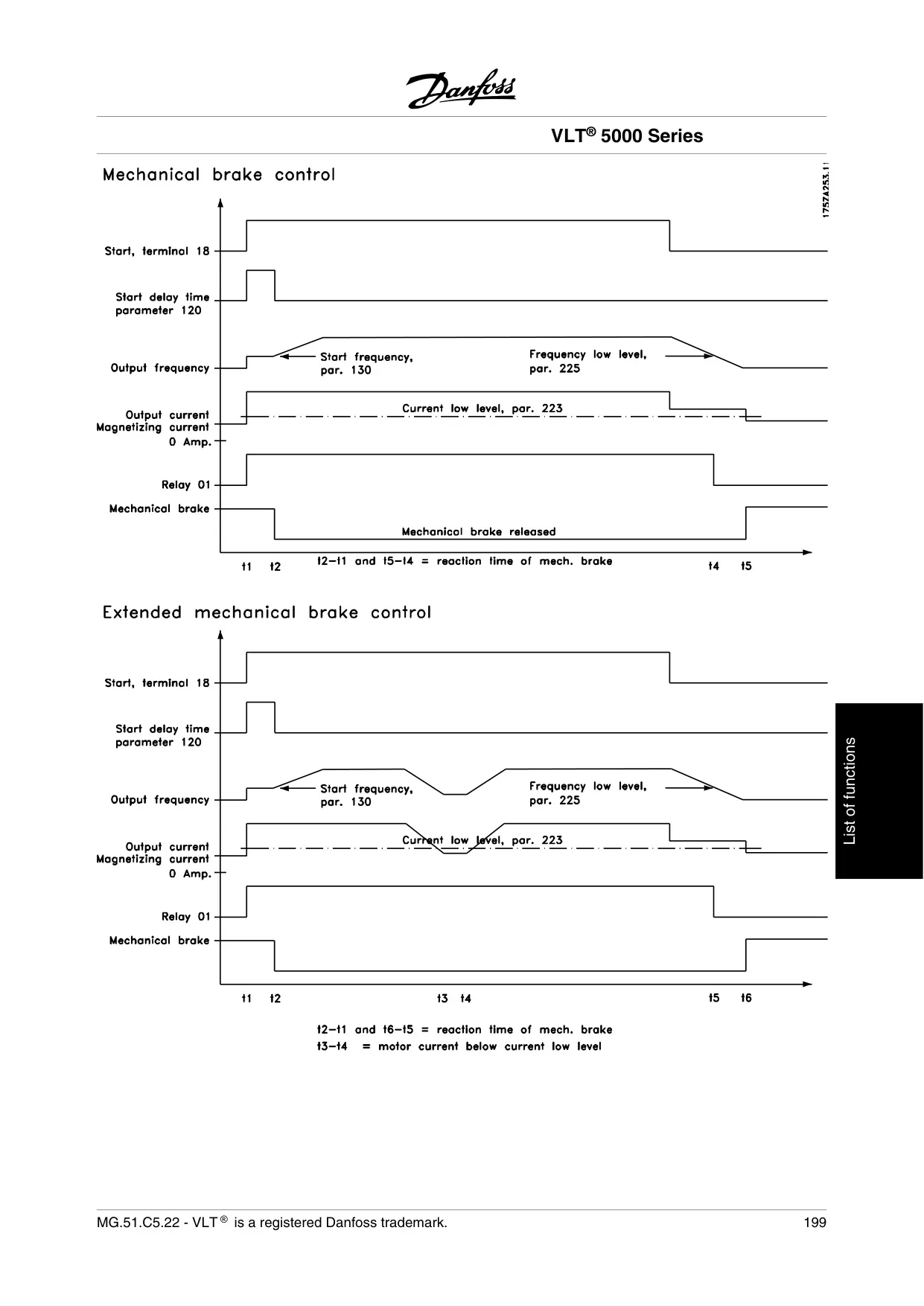
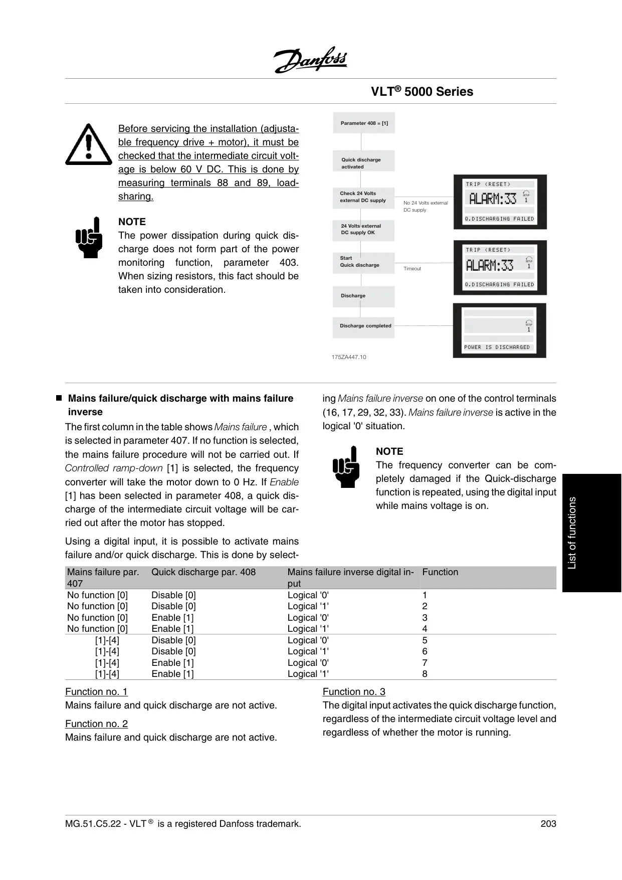
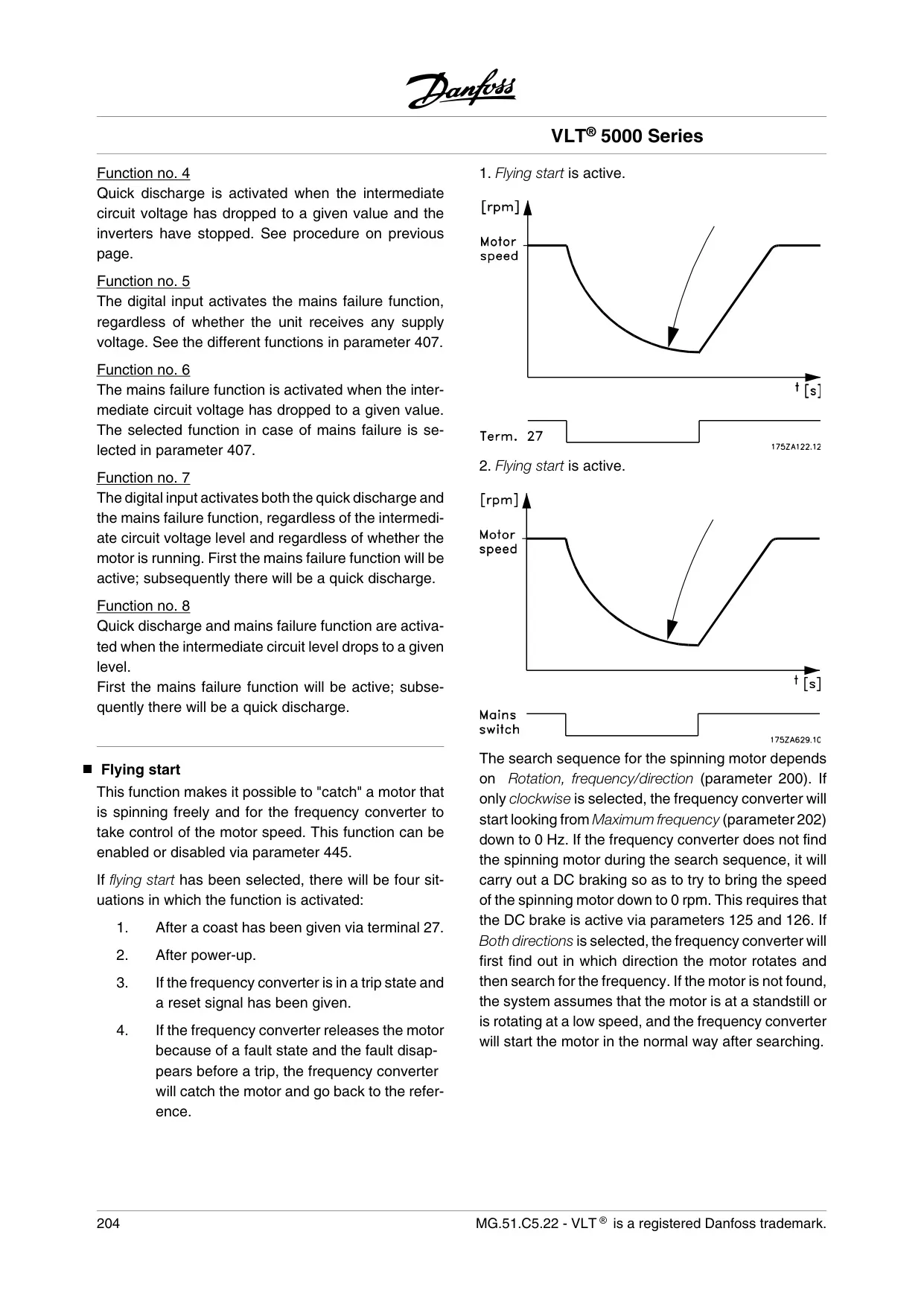
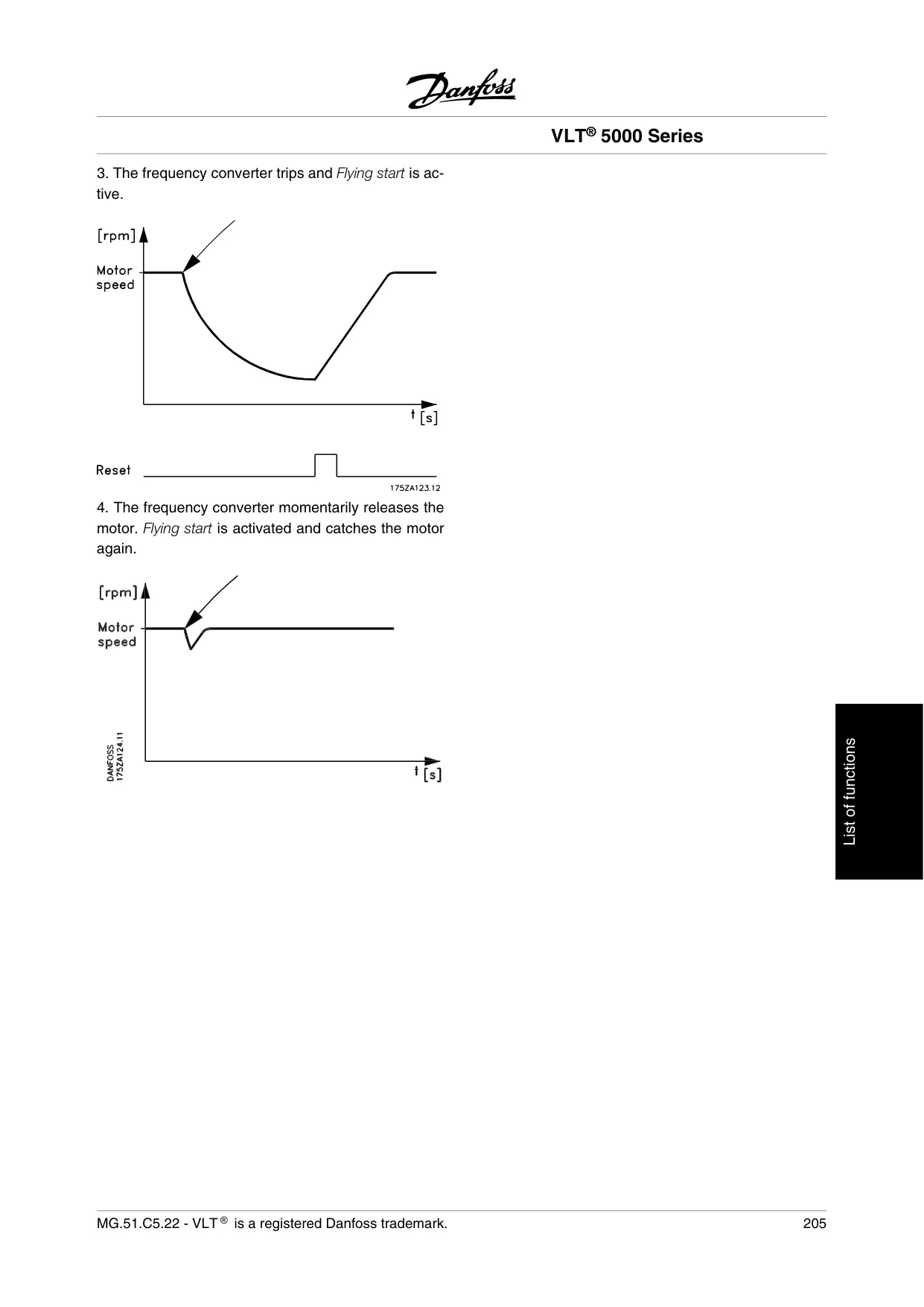
The drive integrates sophisticated braking functions, including resistor braking and overvoltage control, to manage regenerative energy and prevent trips. For specific needs, Quick Discharge rapidly de-energizes intermediate circuit capacitors. Flying Start allows the drive to seamlessly take control of a freely spinning motor, enhancing operational continuity and safety during power fluctuations or restarts.
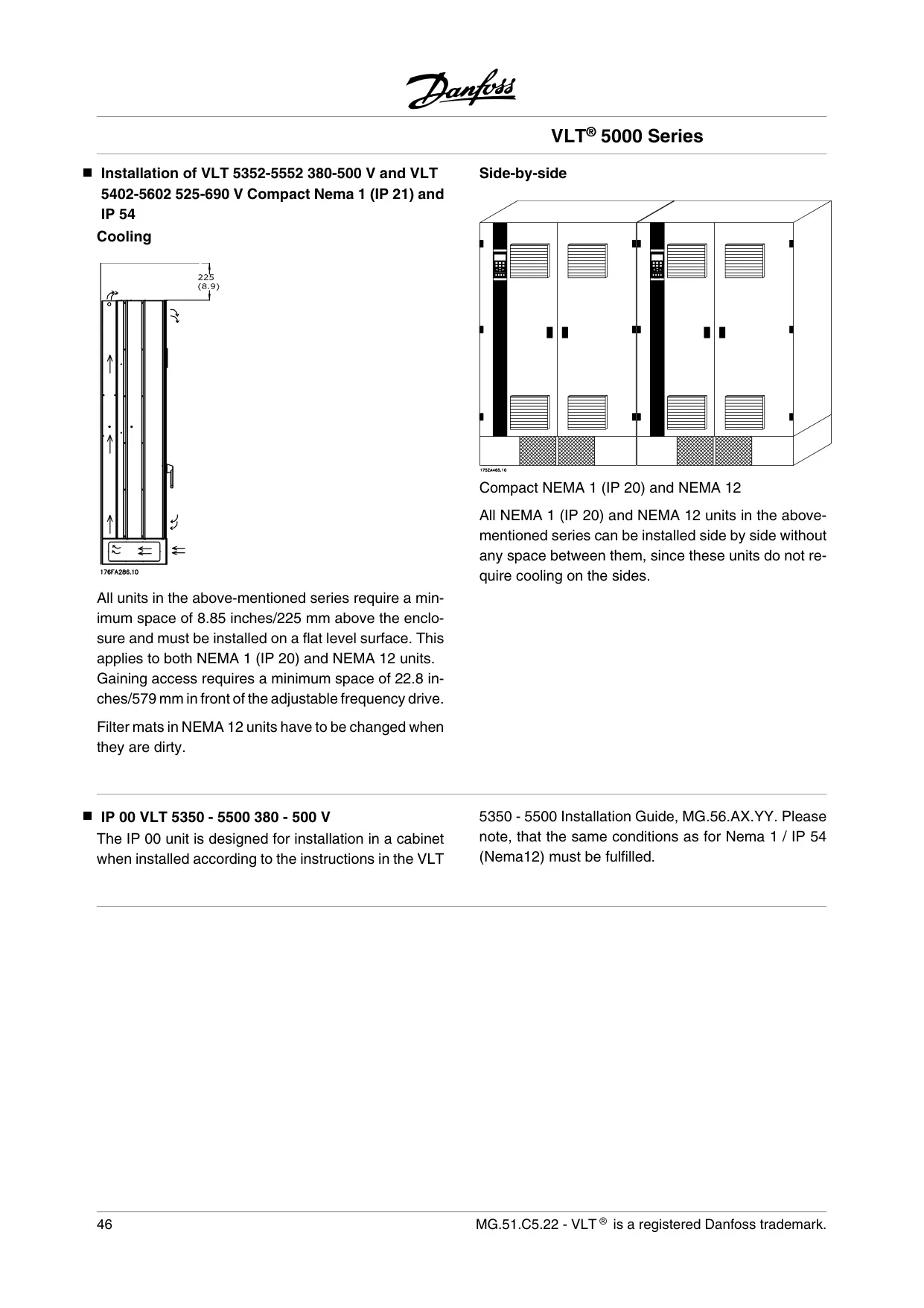
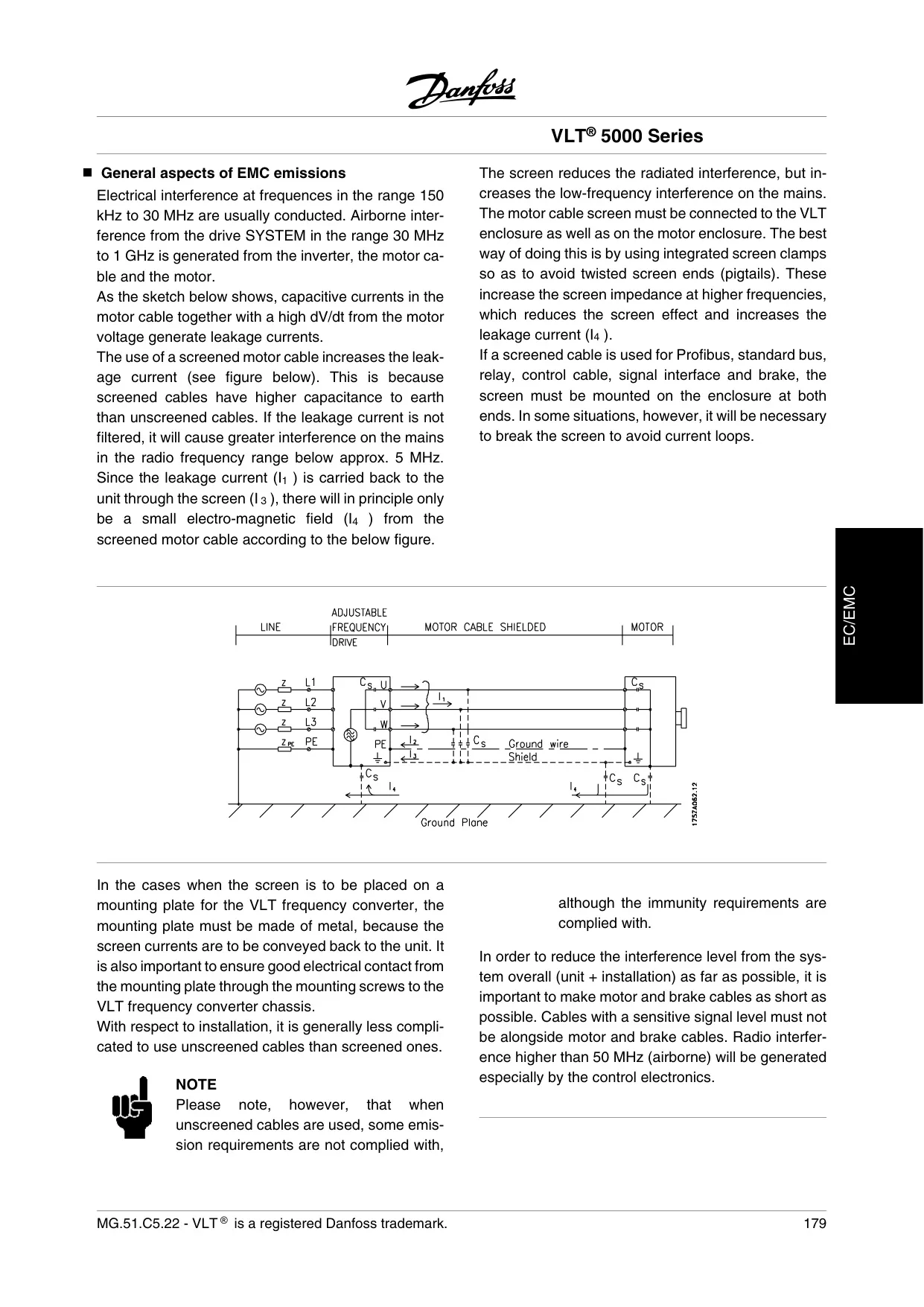
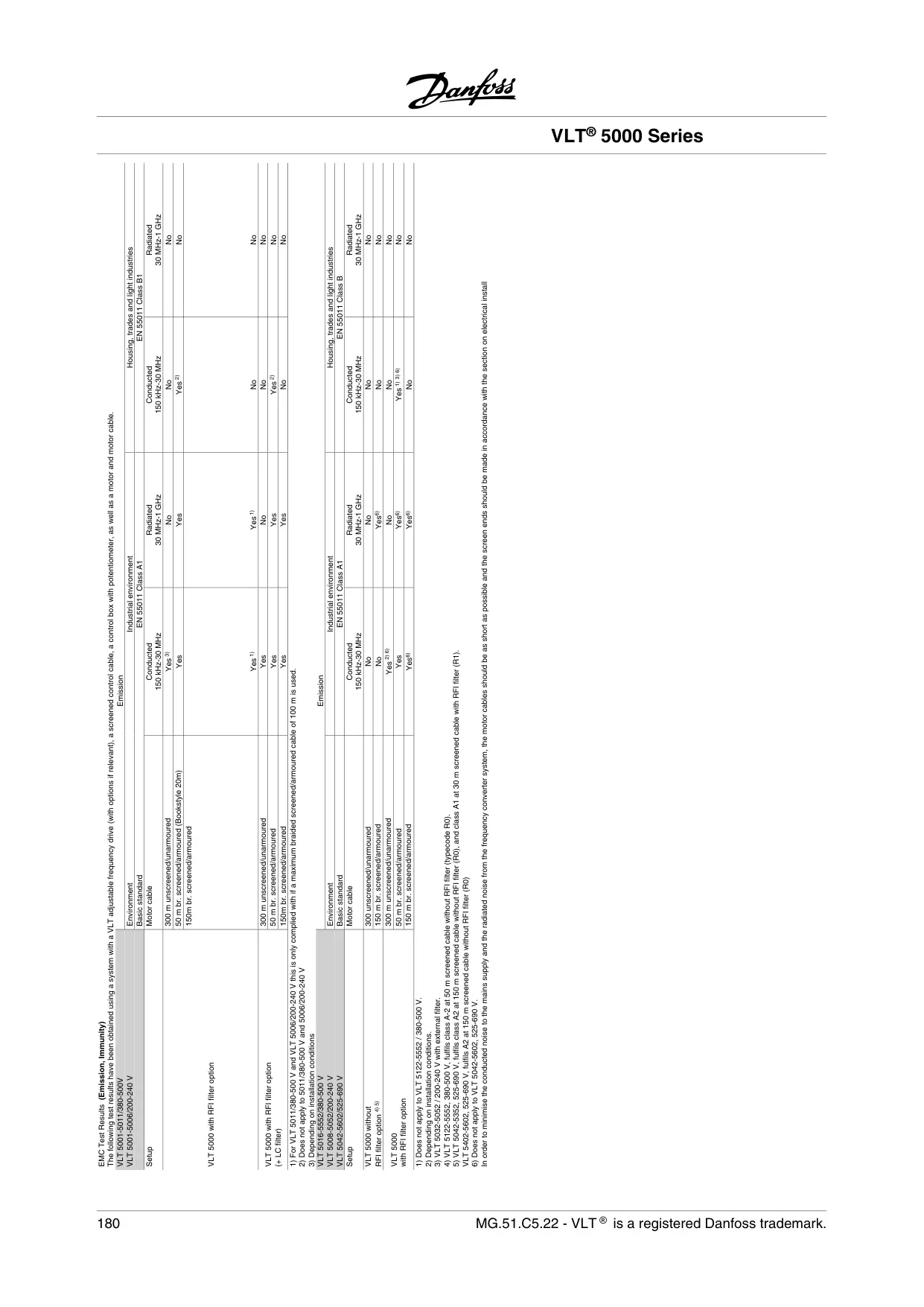
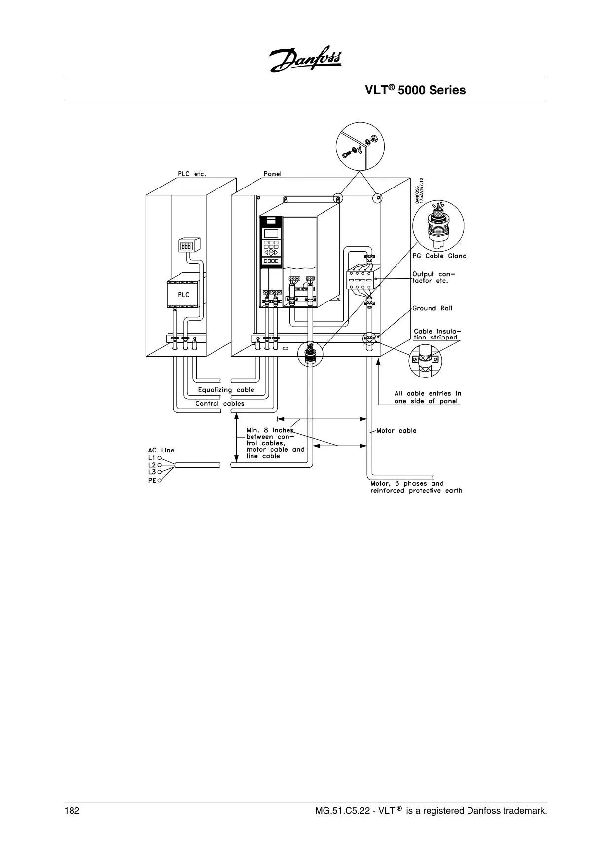
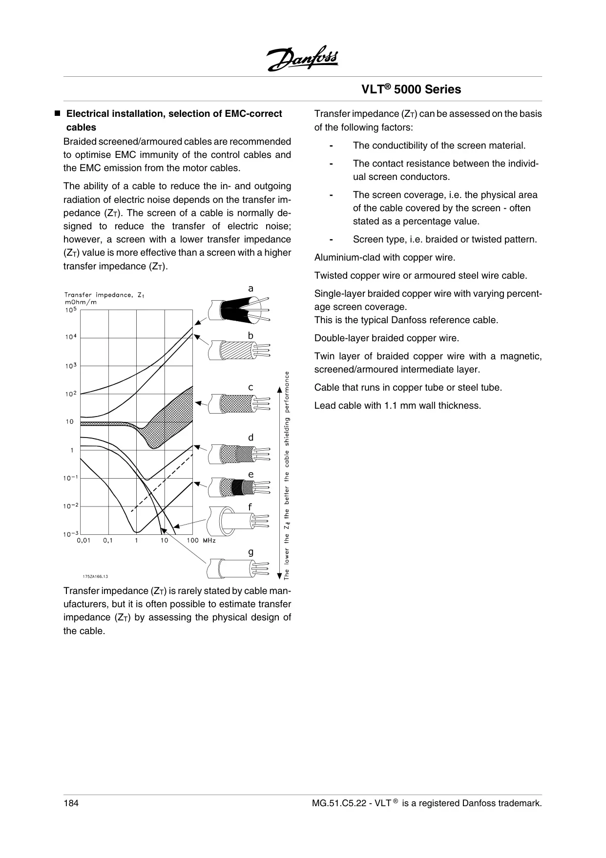
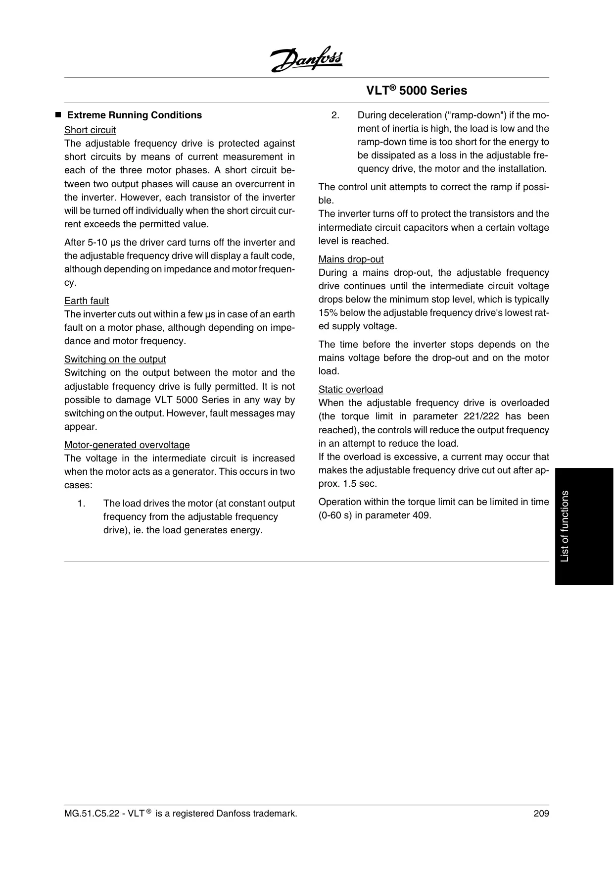
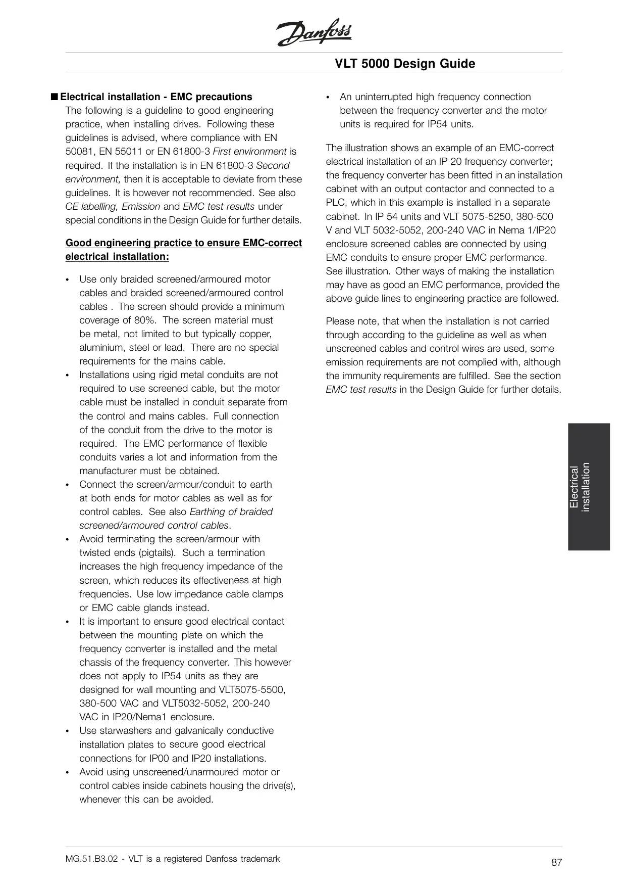
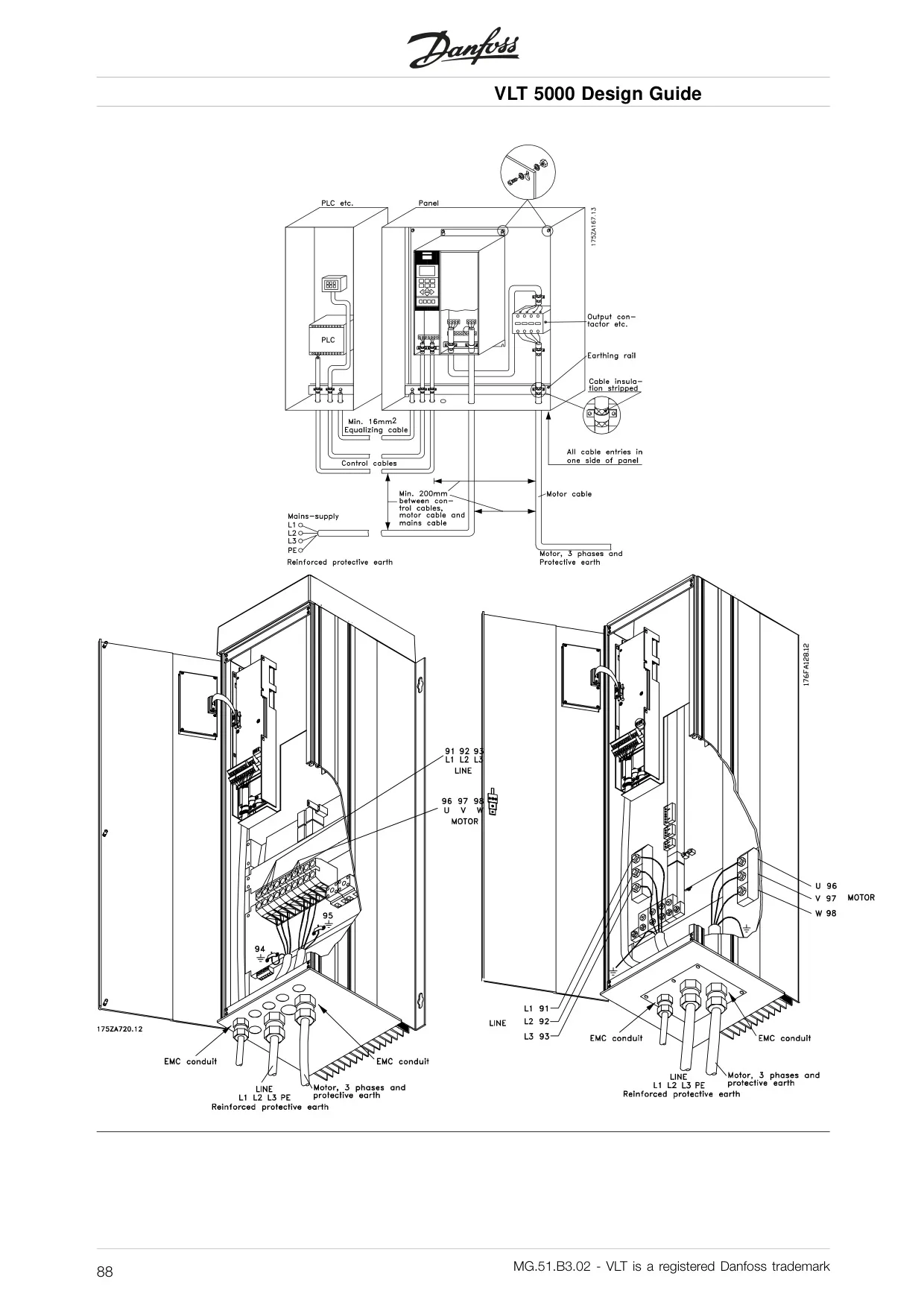
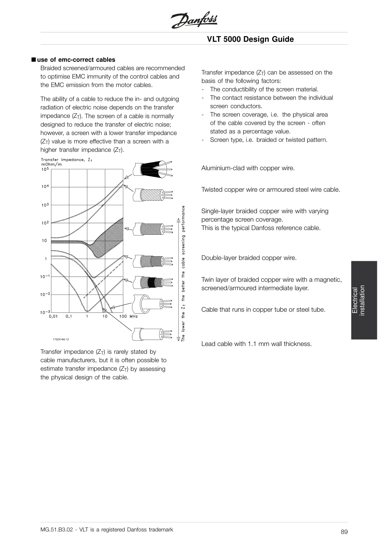
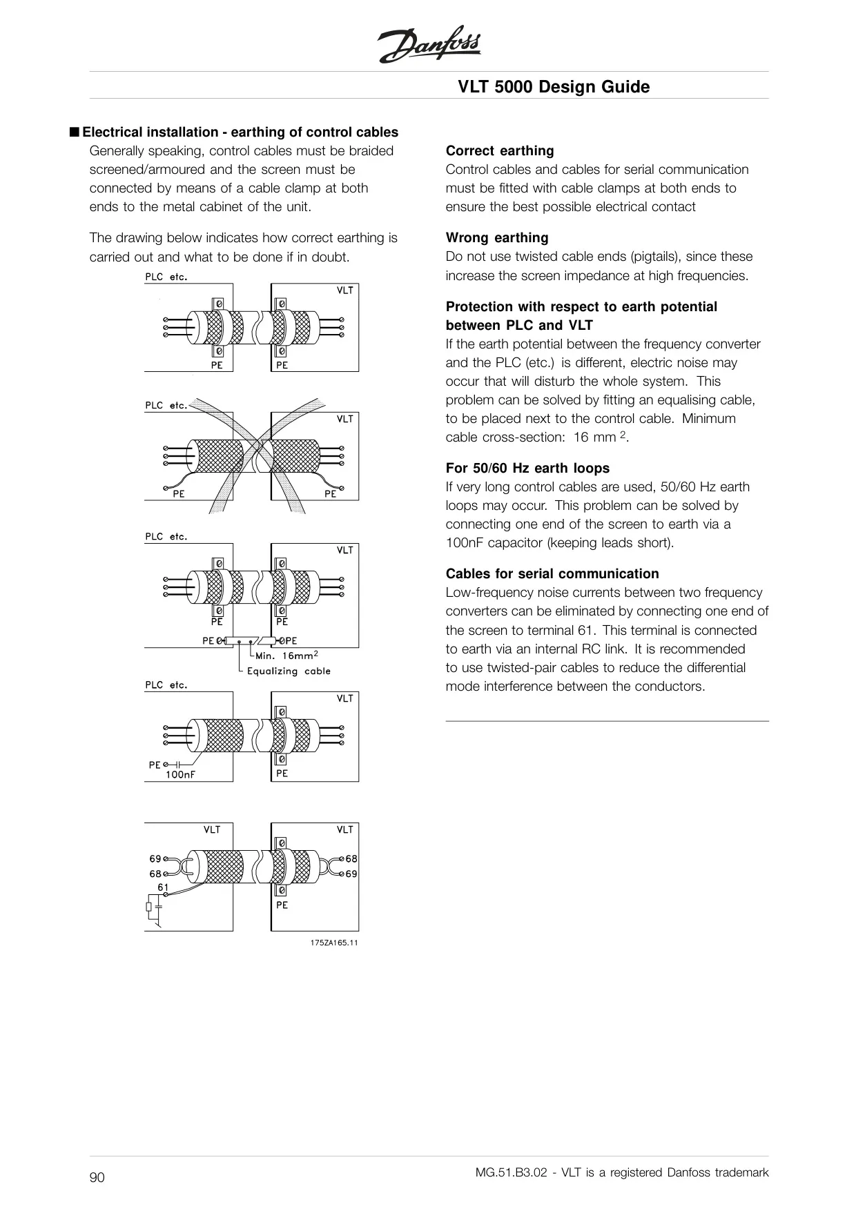
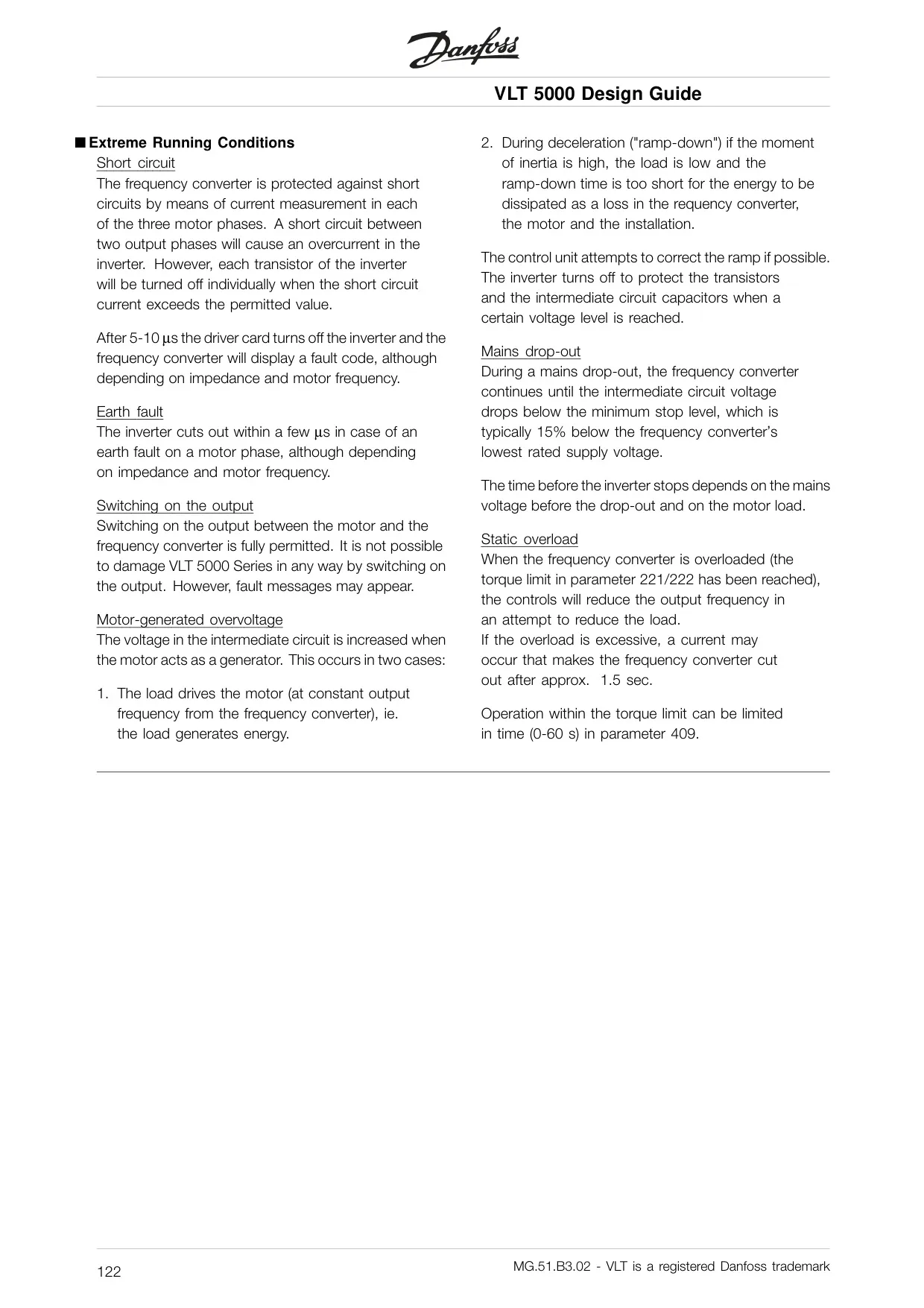
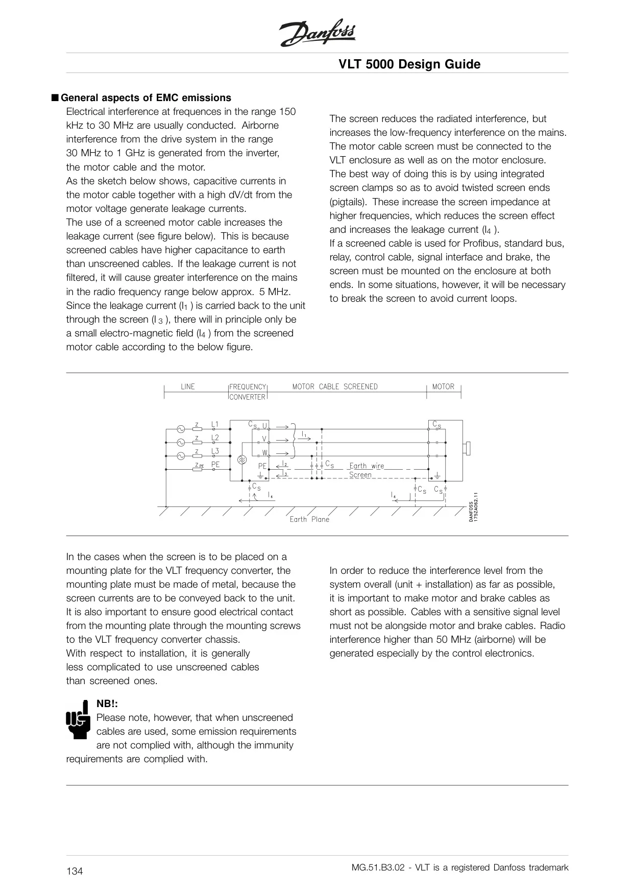
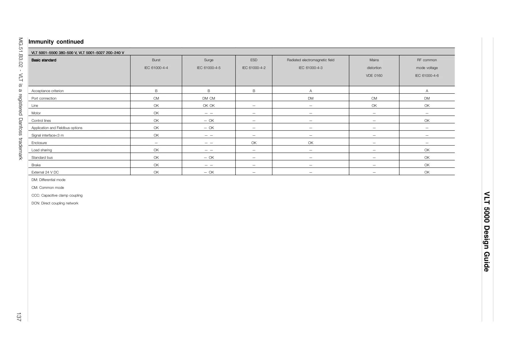
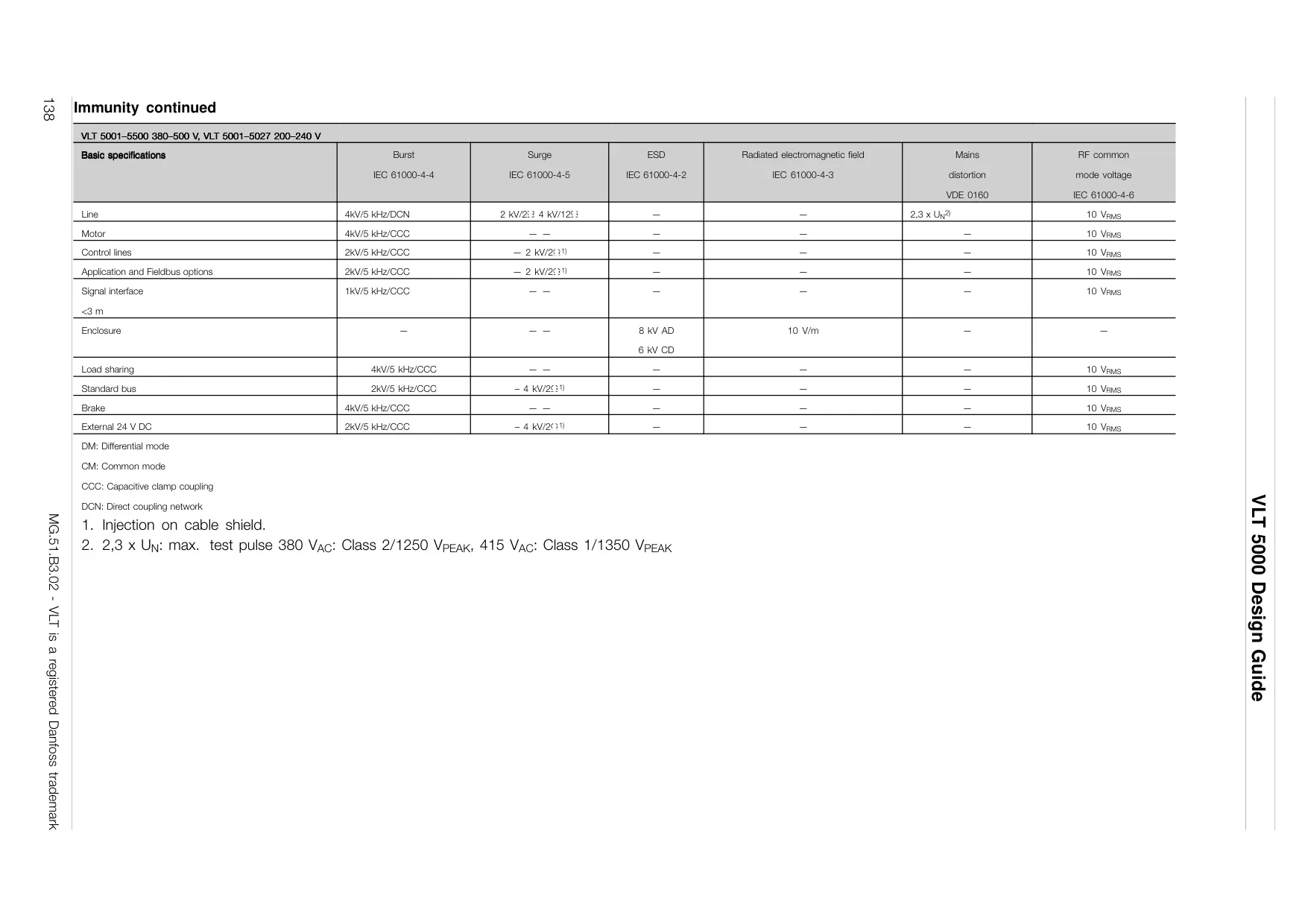
EMC (Electromagnetic Compatibility) compliance is addressed through detailed installation guidelines, emphasizing the use of screened cables and proper earthing to minimize interference. The unit's robust design also considers extreme running conditions, such as short circuits, earth faults, and mains drop-outs, providing resilient performance in demanding industrial environments.
Frequently Asked Questions (FAQs)
Can't find the answer you need? Here are some frequently asked questions about the Danfoss VLT 5000 Variable Frequency Drive, and we answer them below.