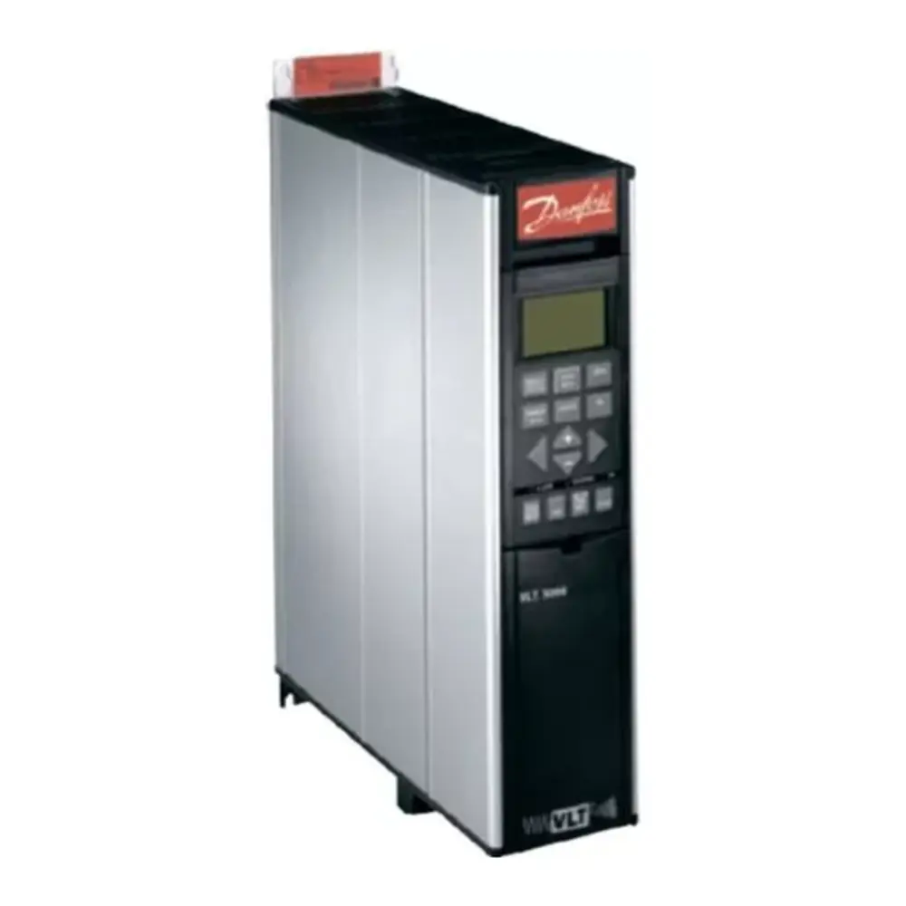
Danfoss AC Drive VLT 2800 Instruction Manual
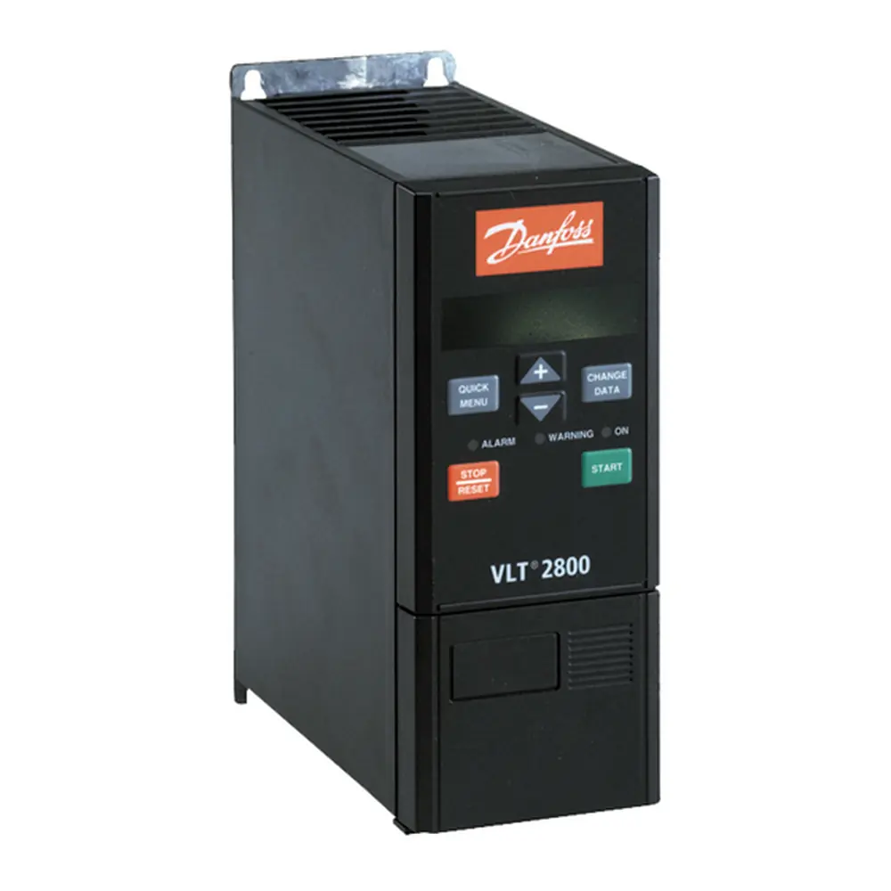
Danfoss AC Drive VLT 2800
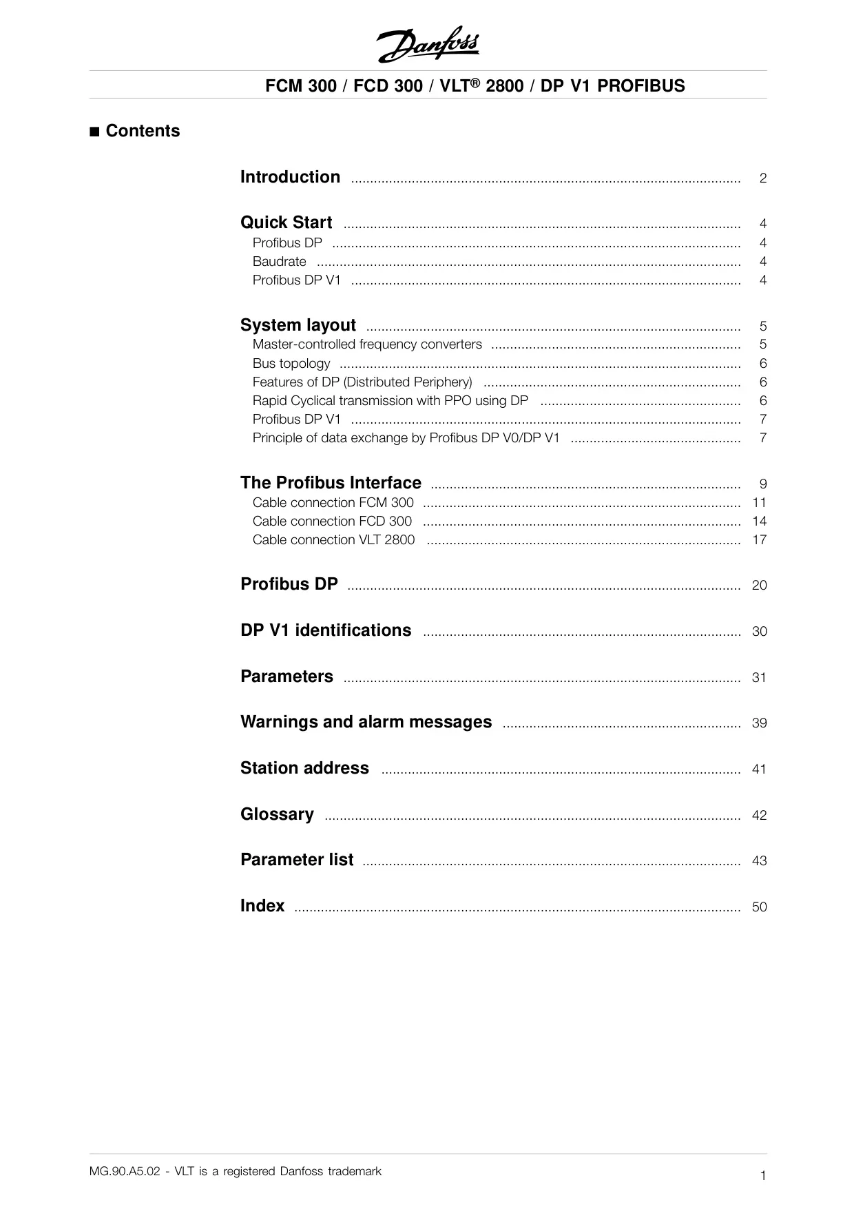
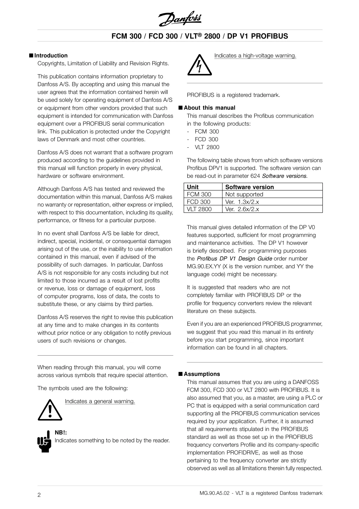
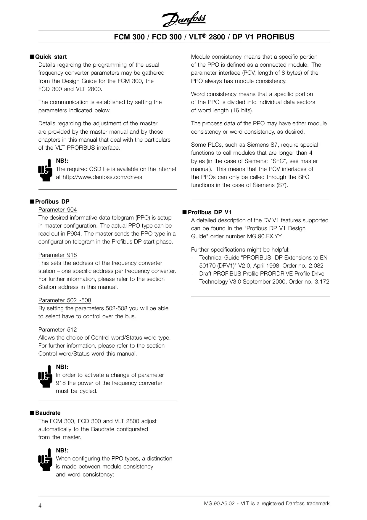

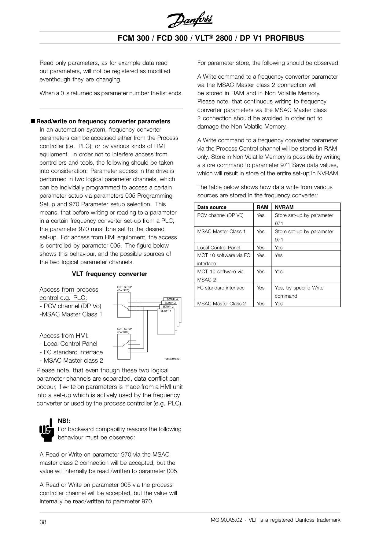
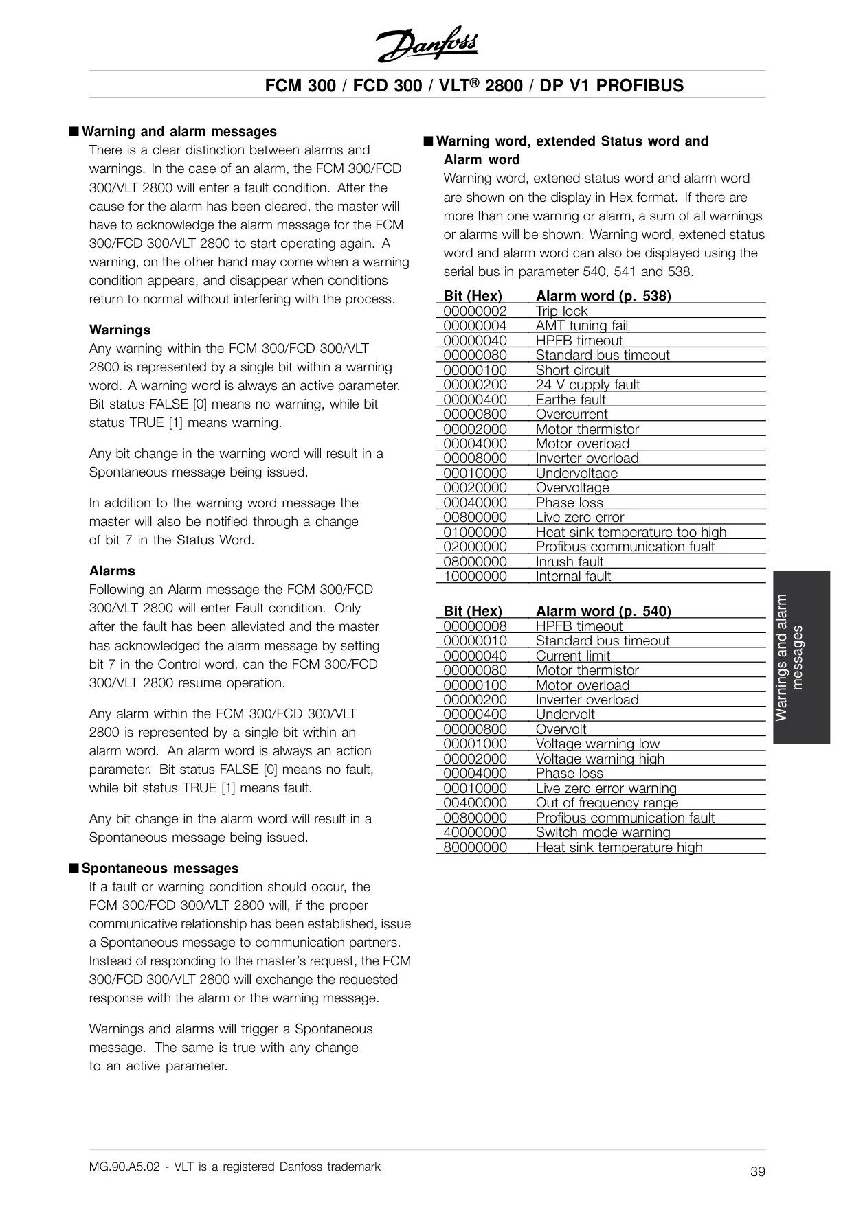
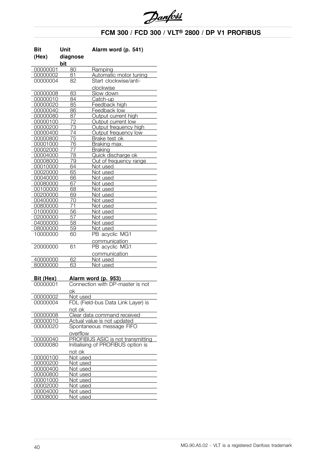
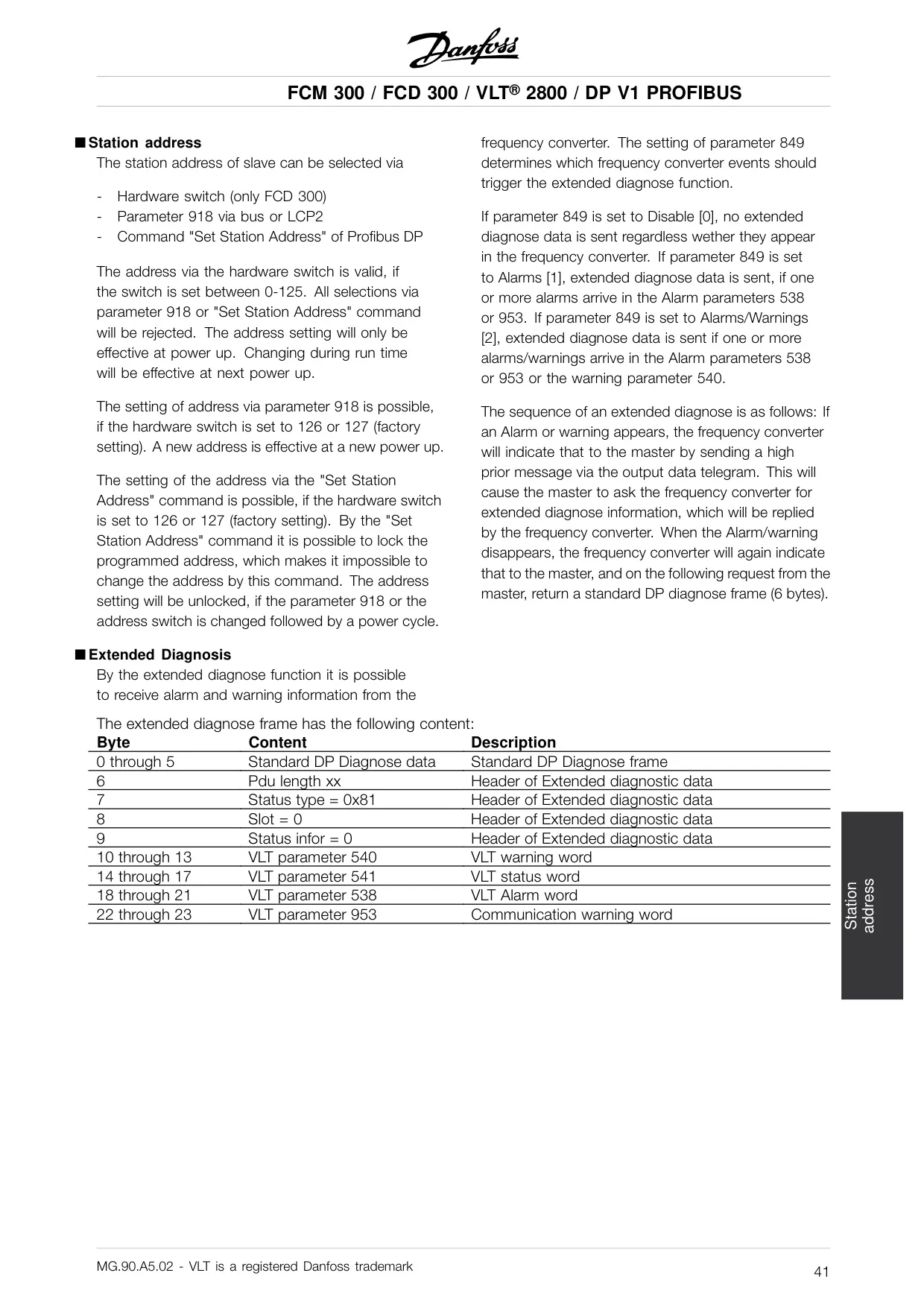


Danfoss AC Drive VLT 2800
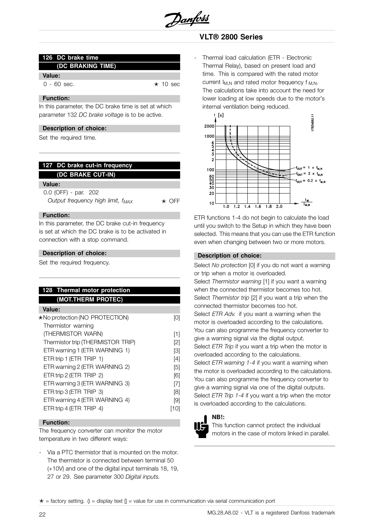
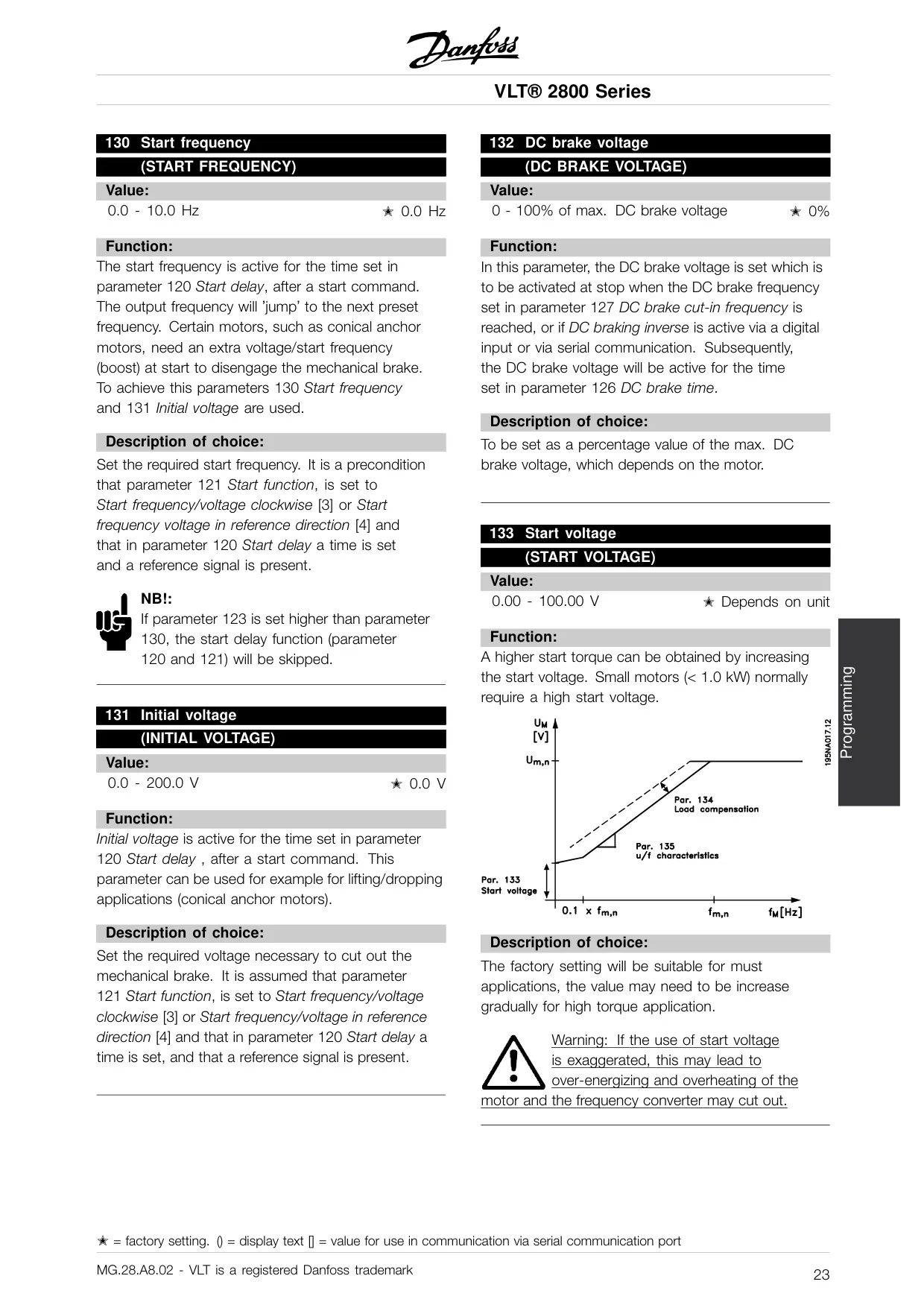
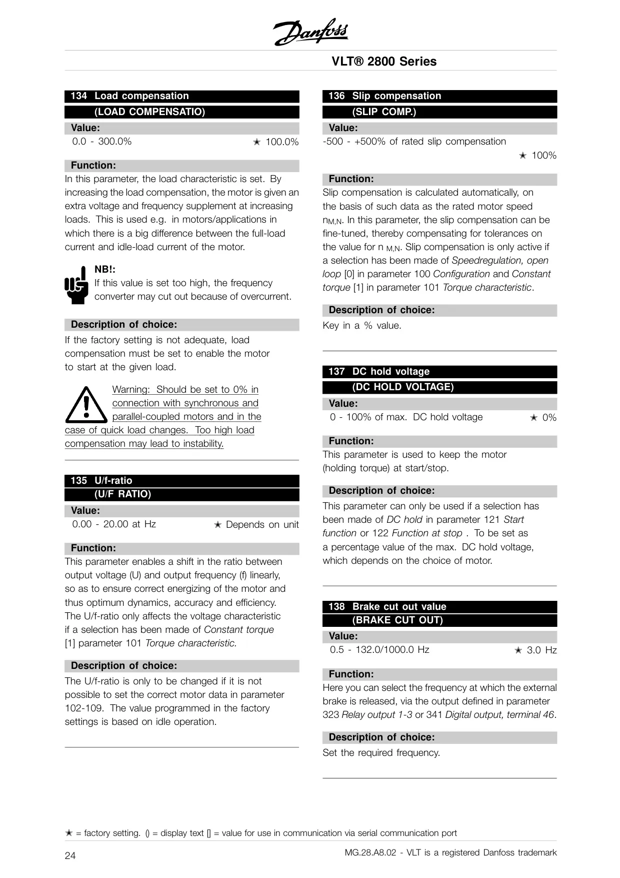
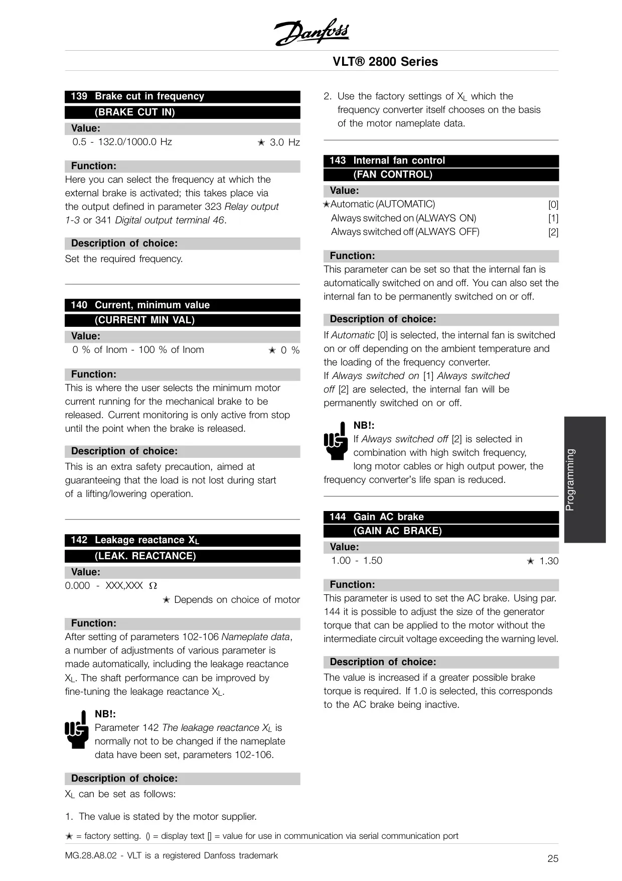
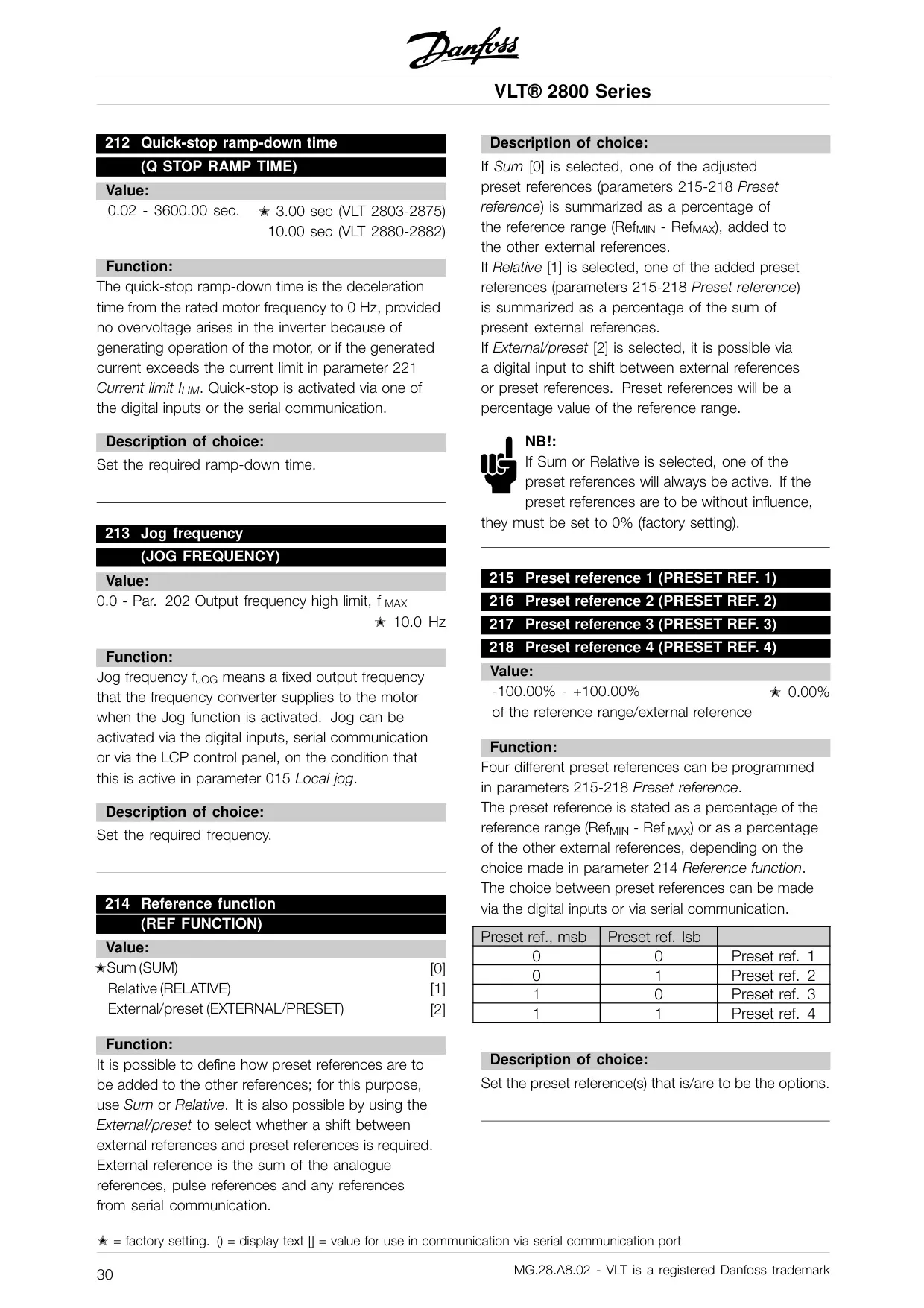
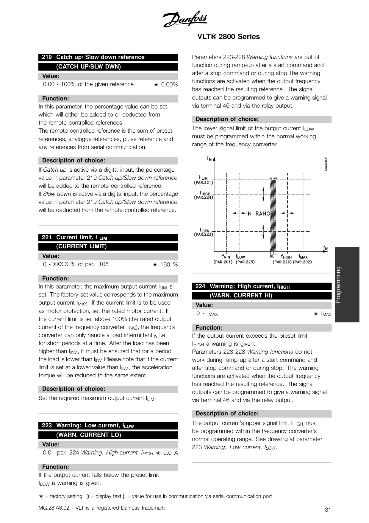
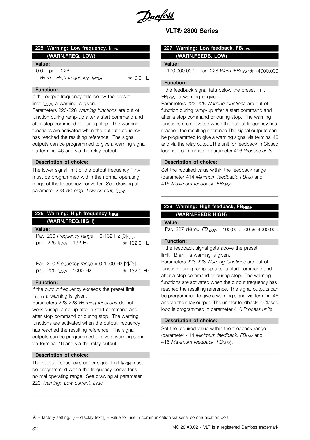
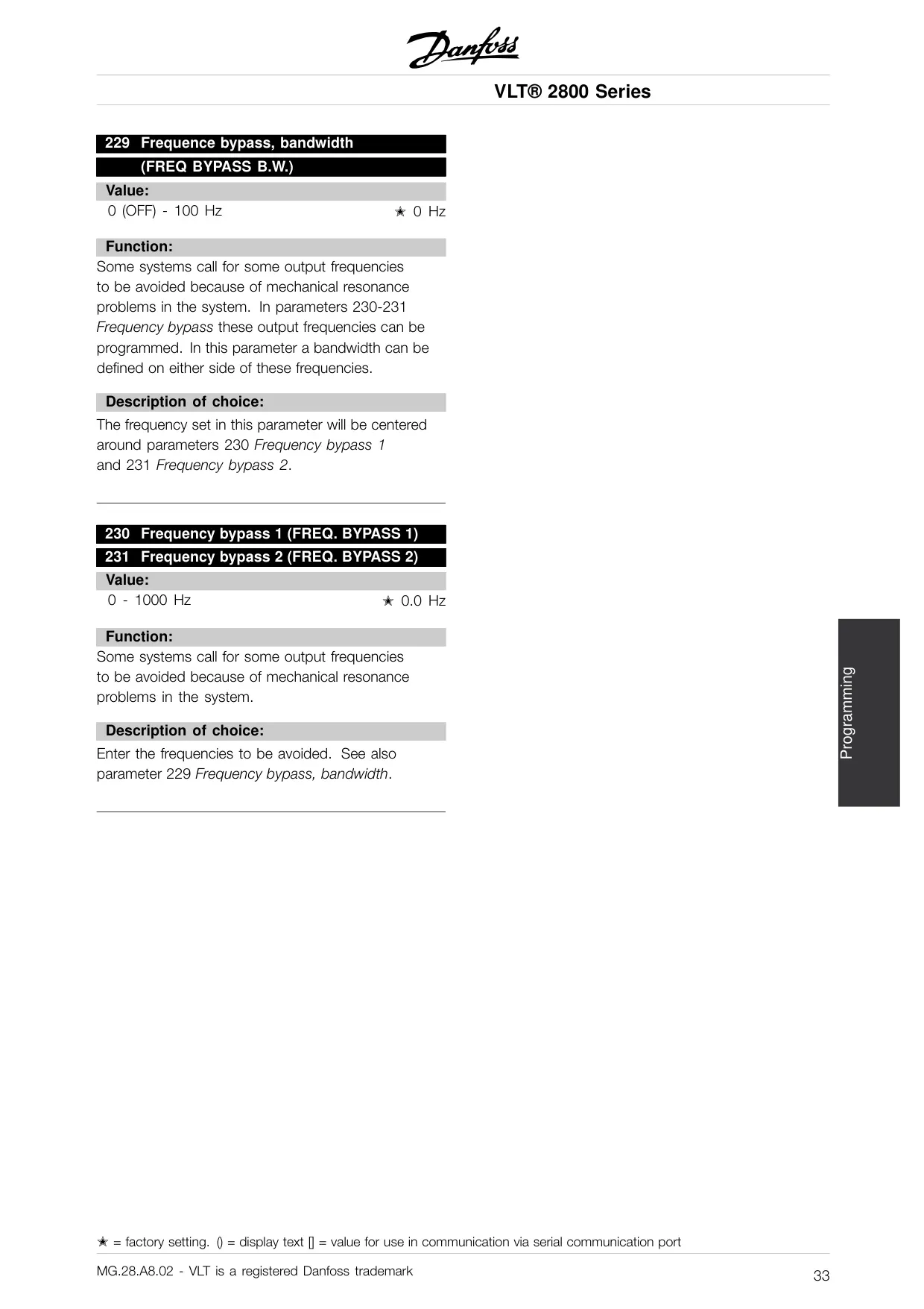
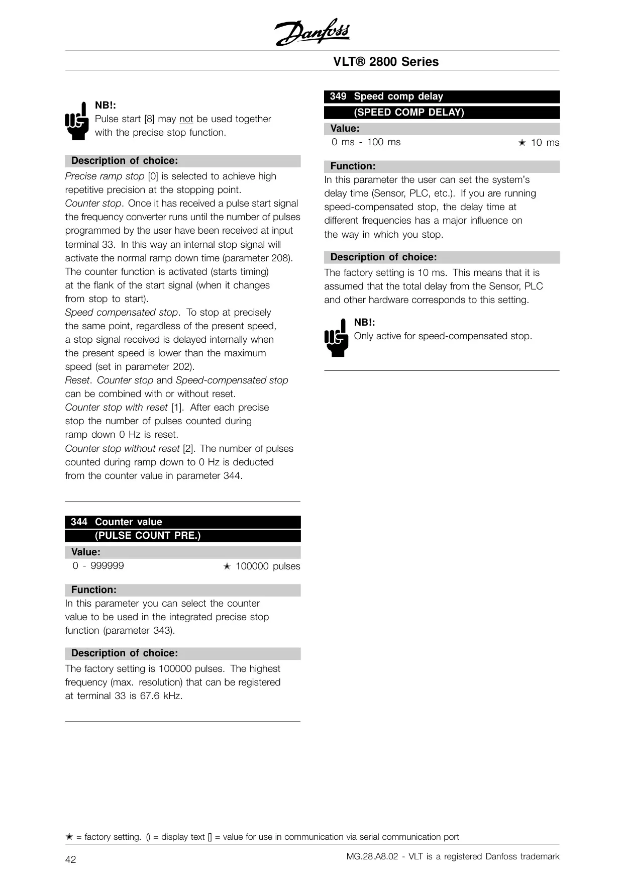
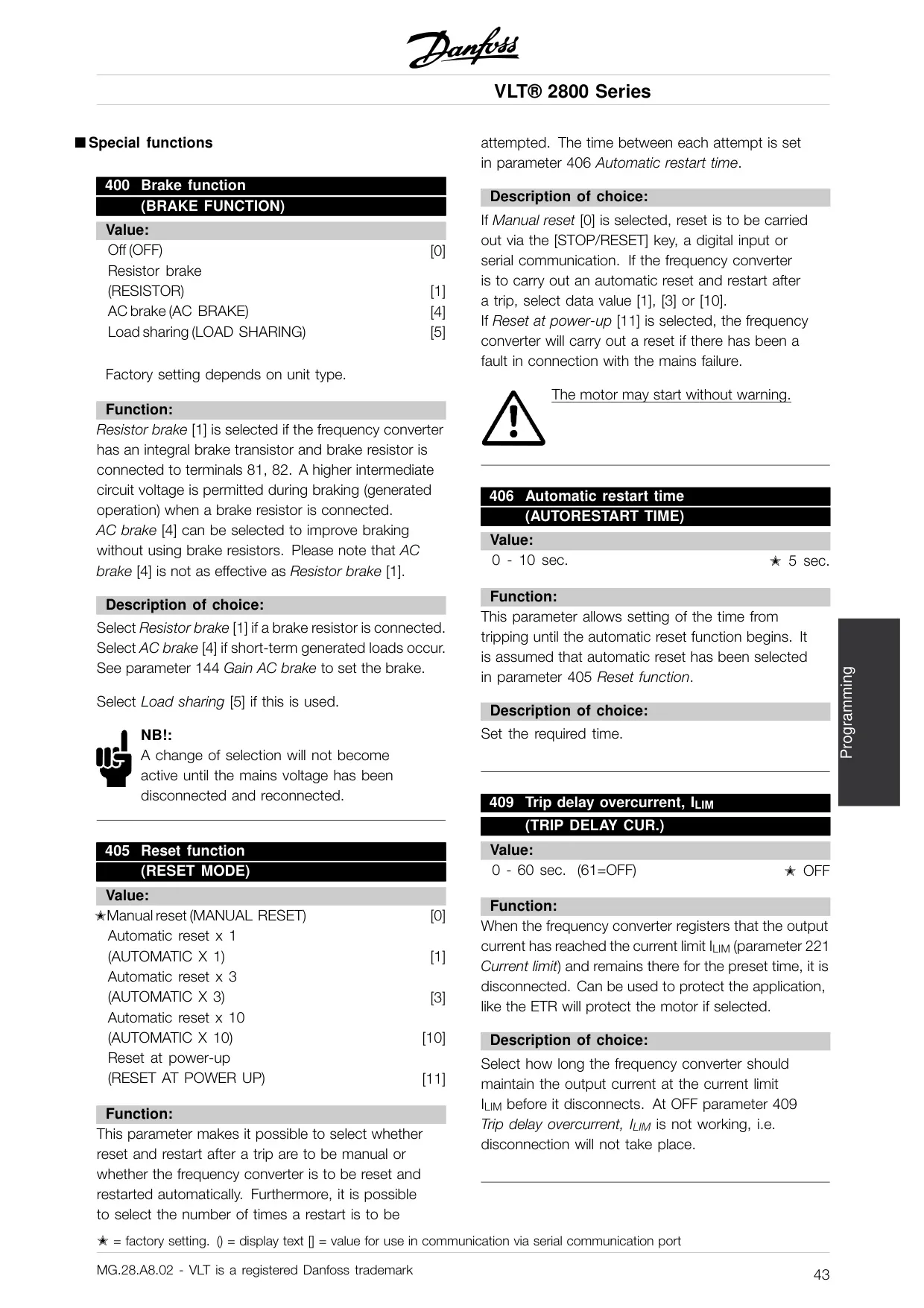
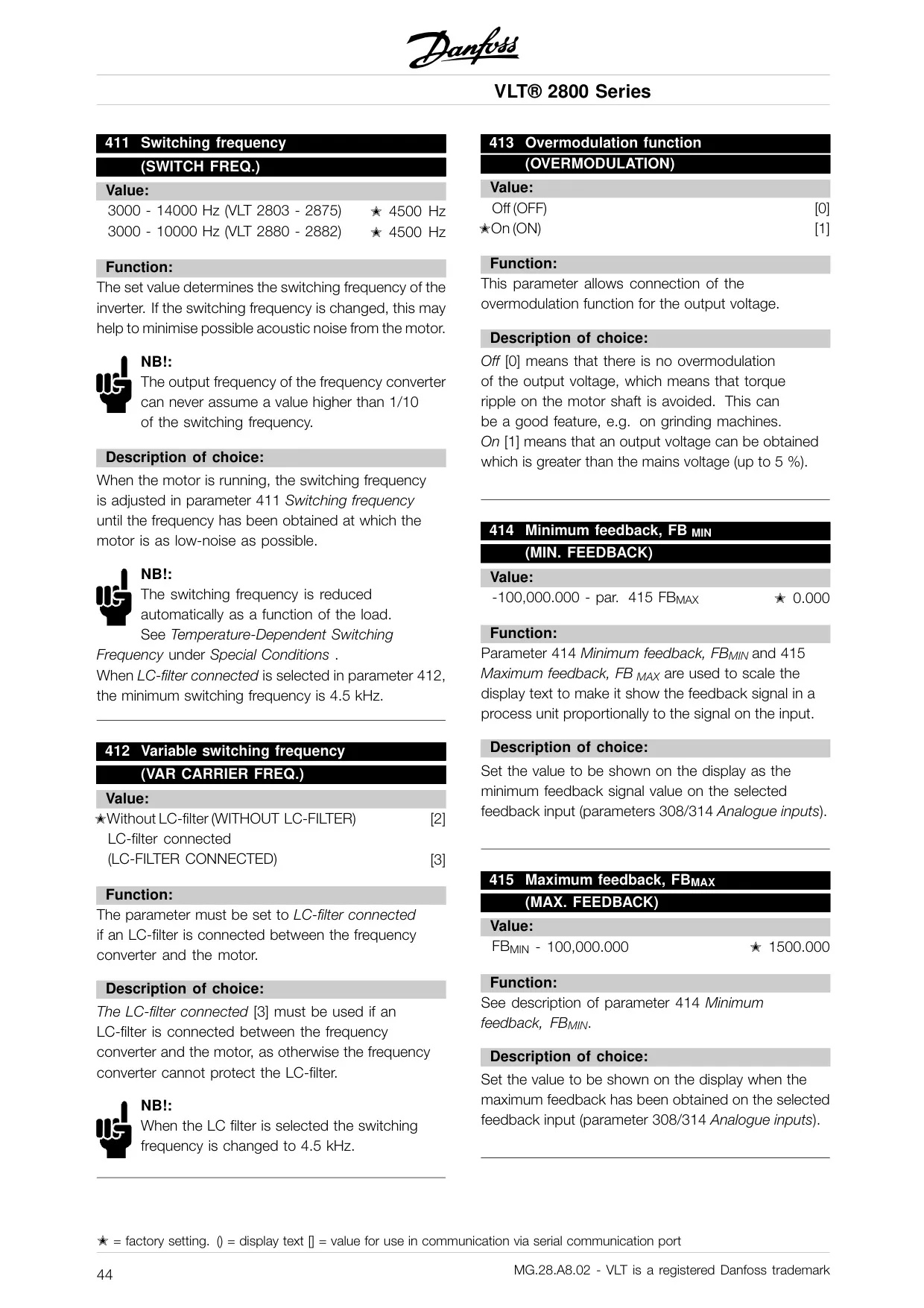
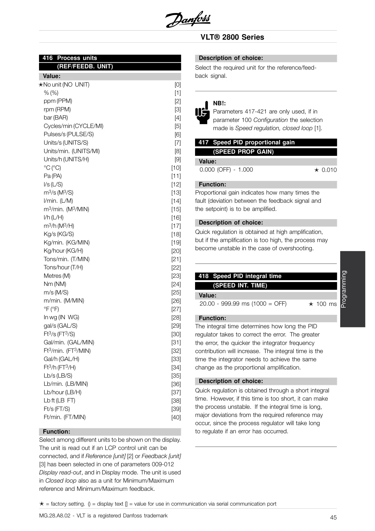
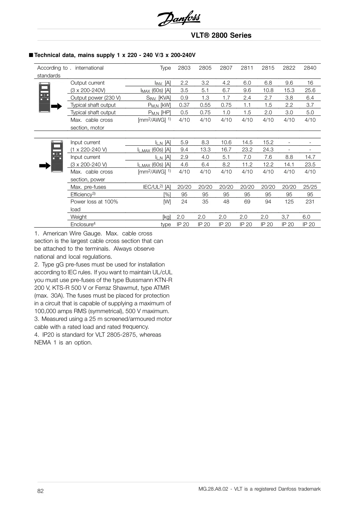
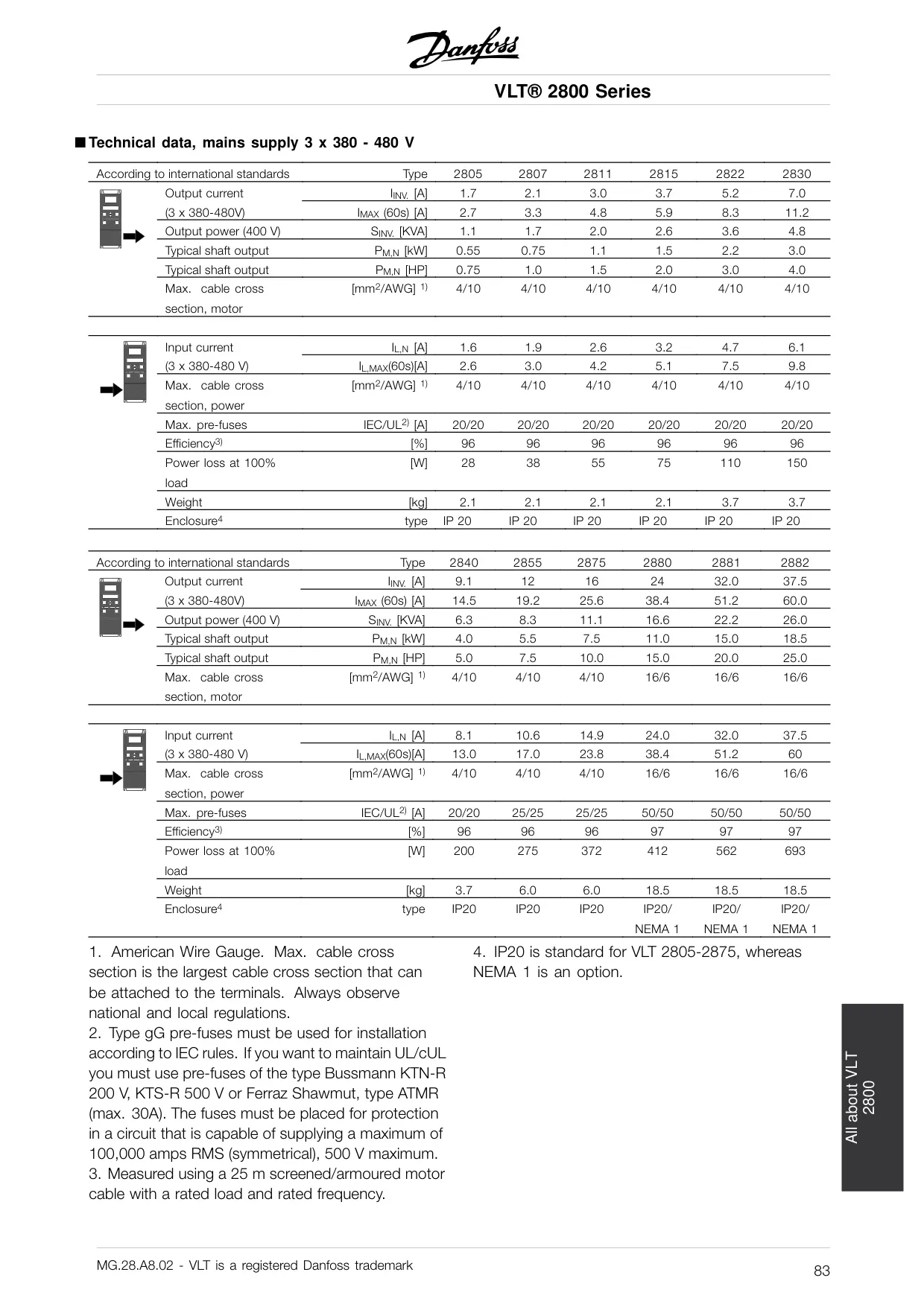
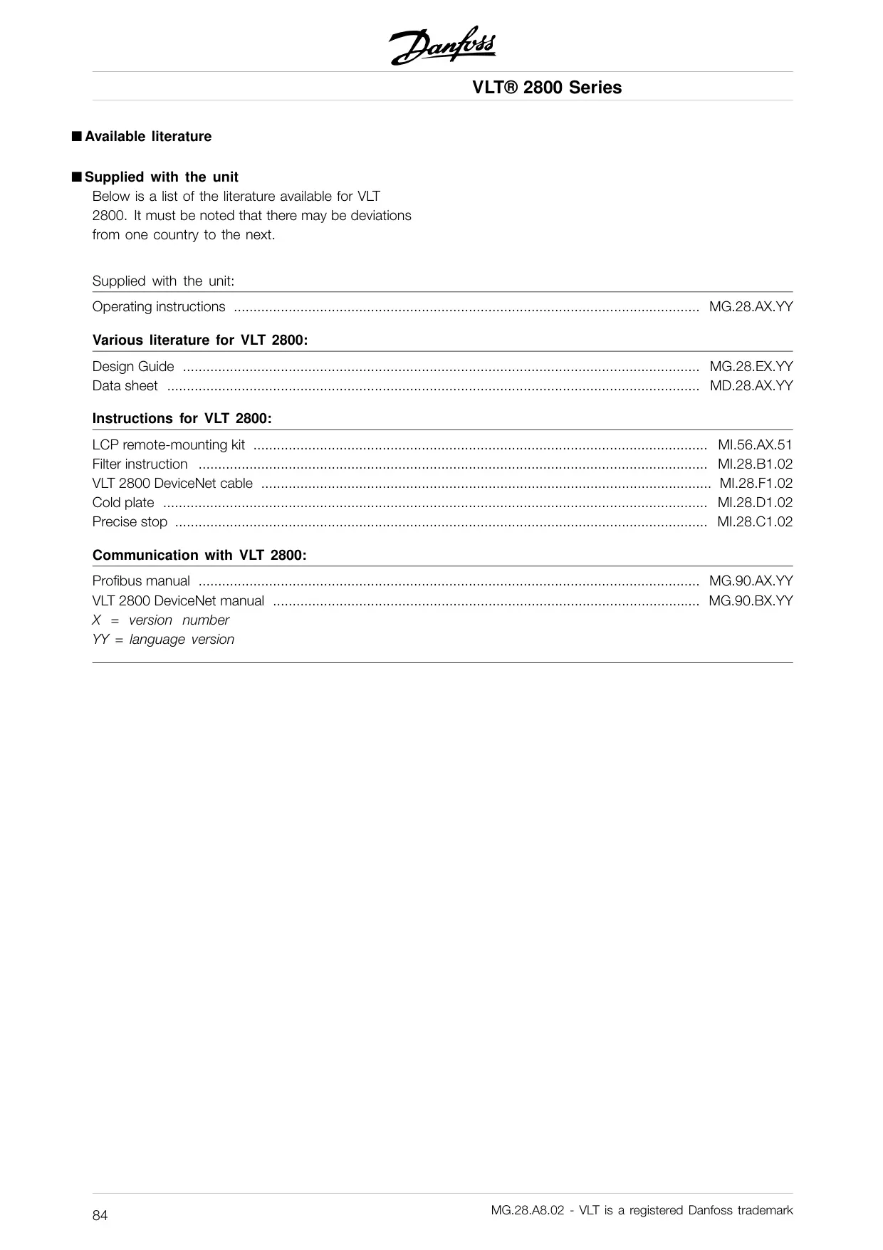

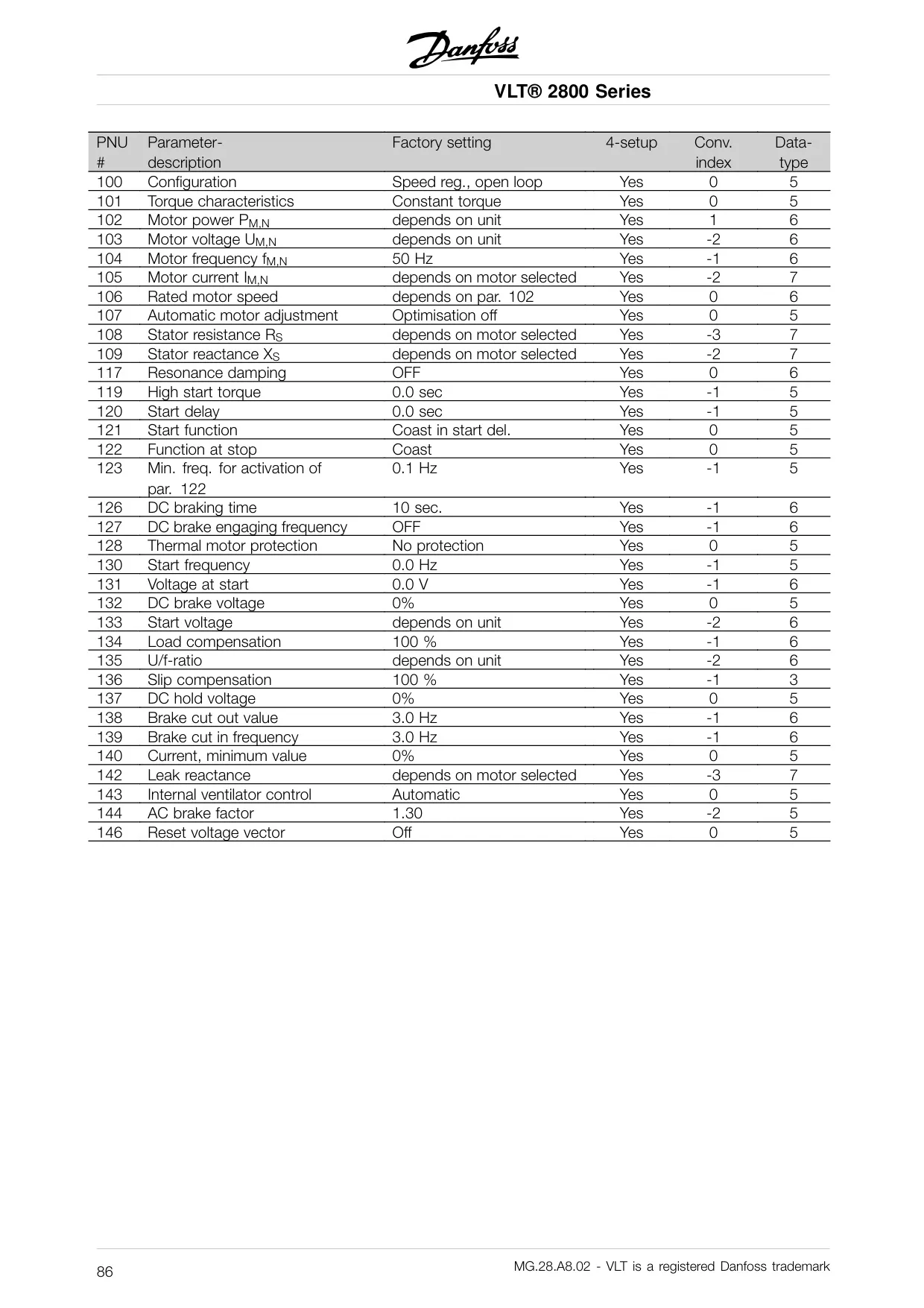
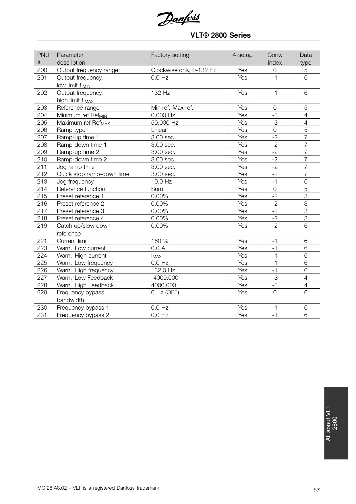
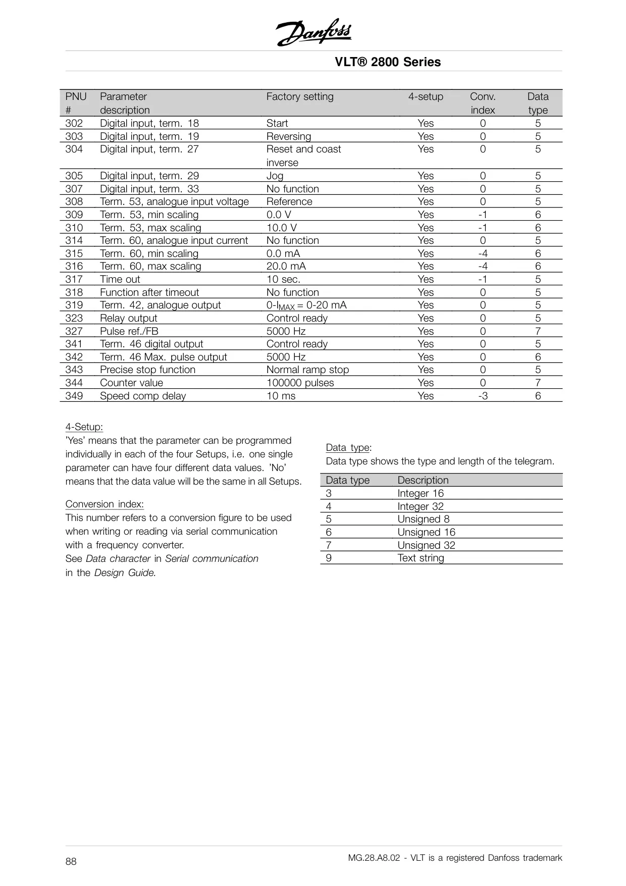
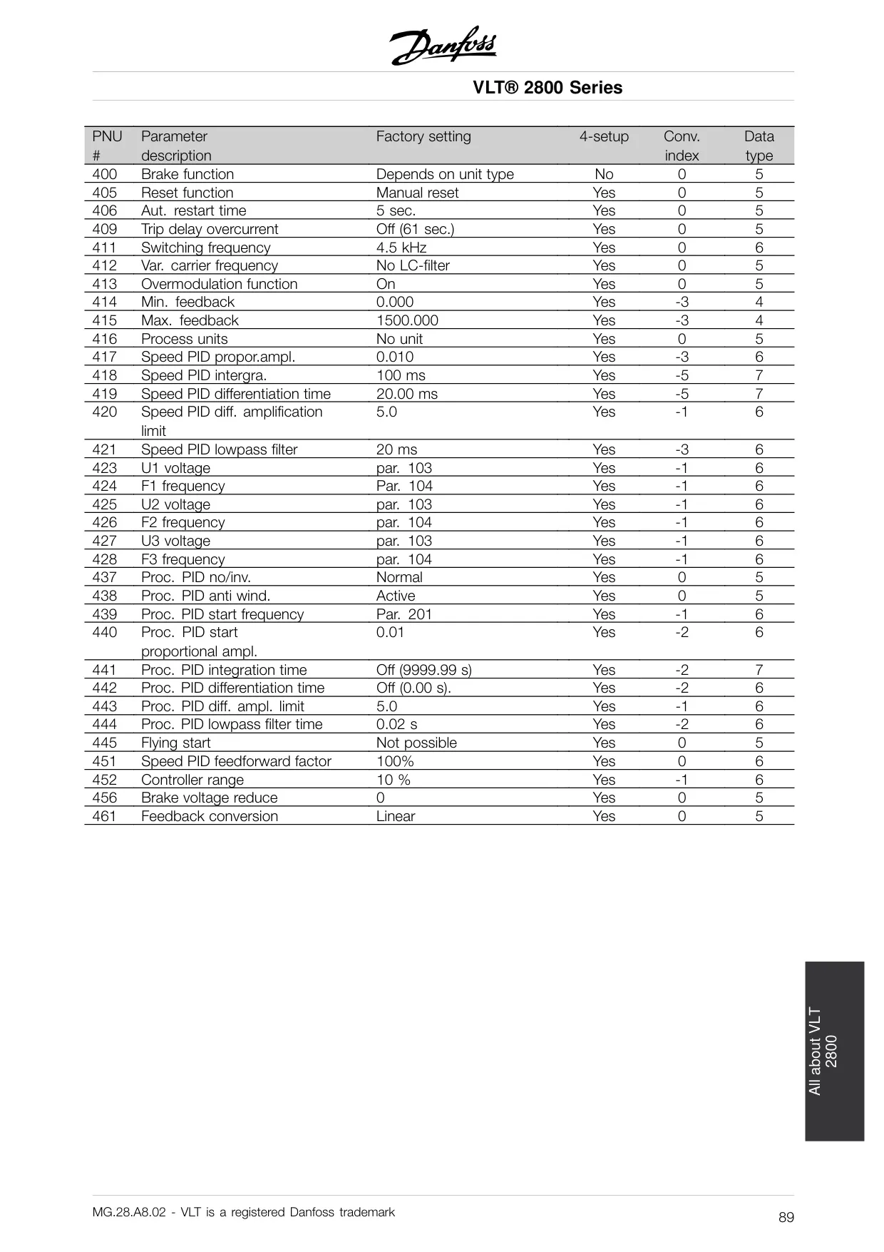
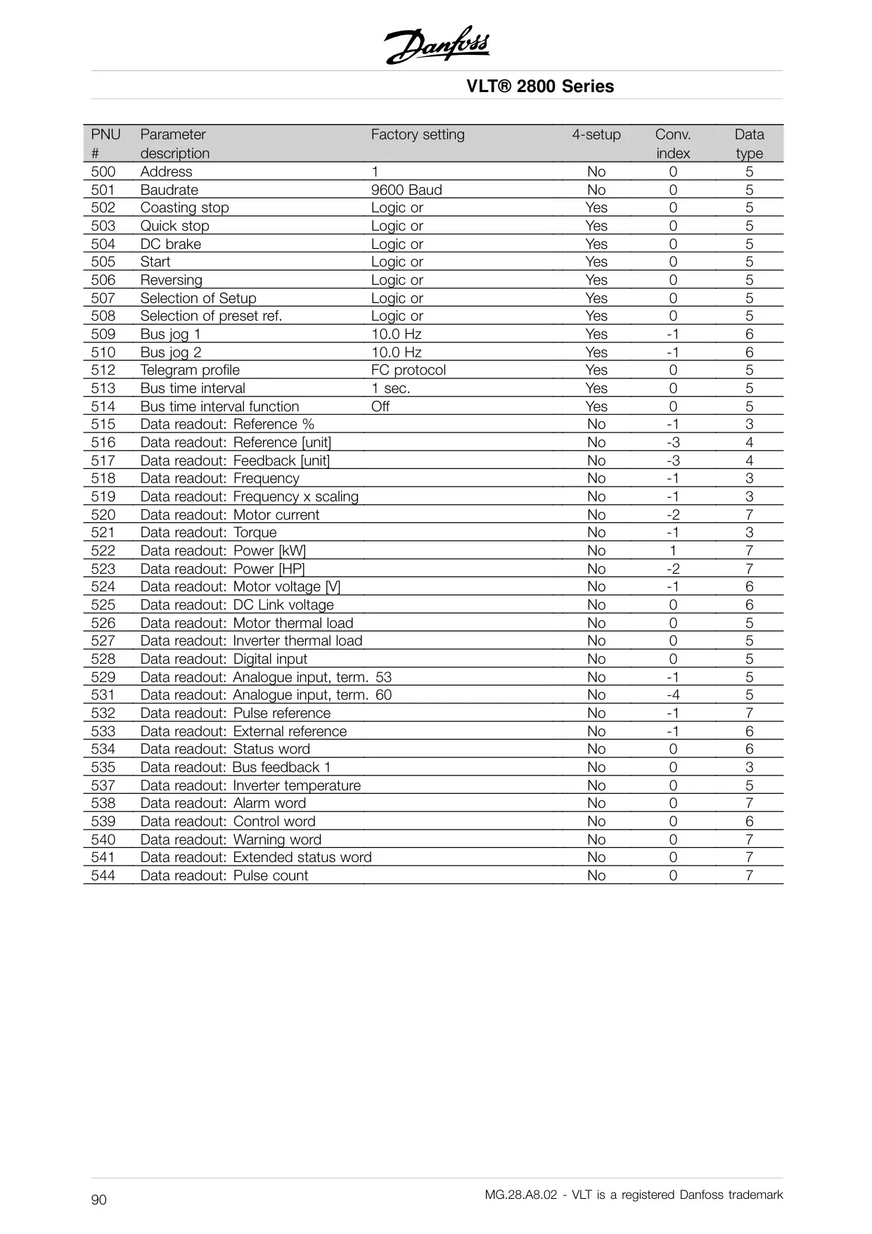
Danfoss AC Drive VLT 2800
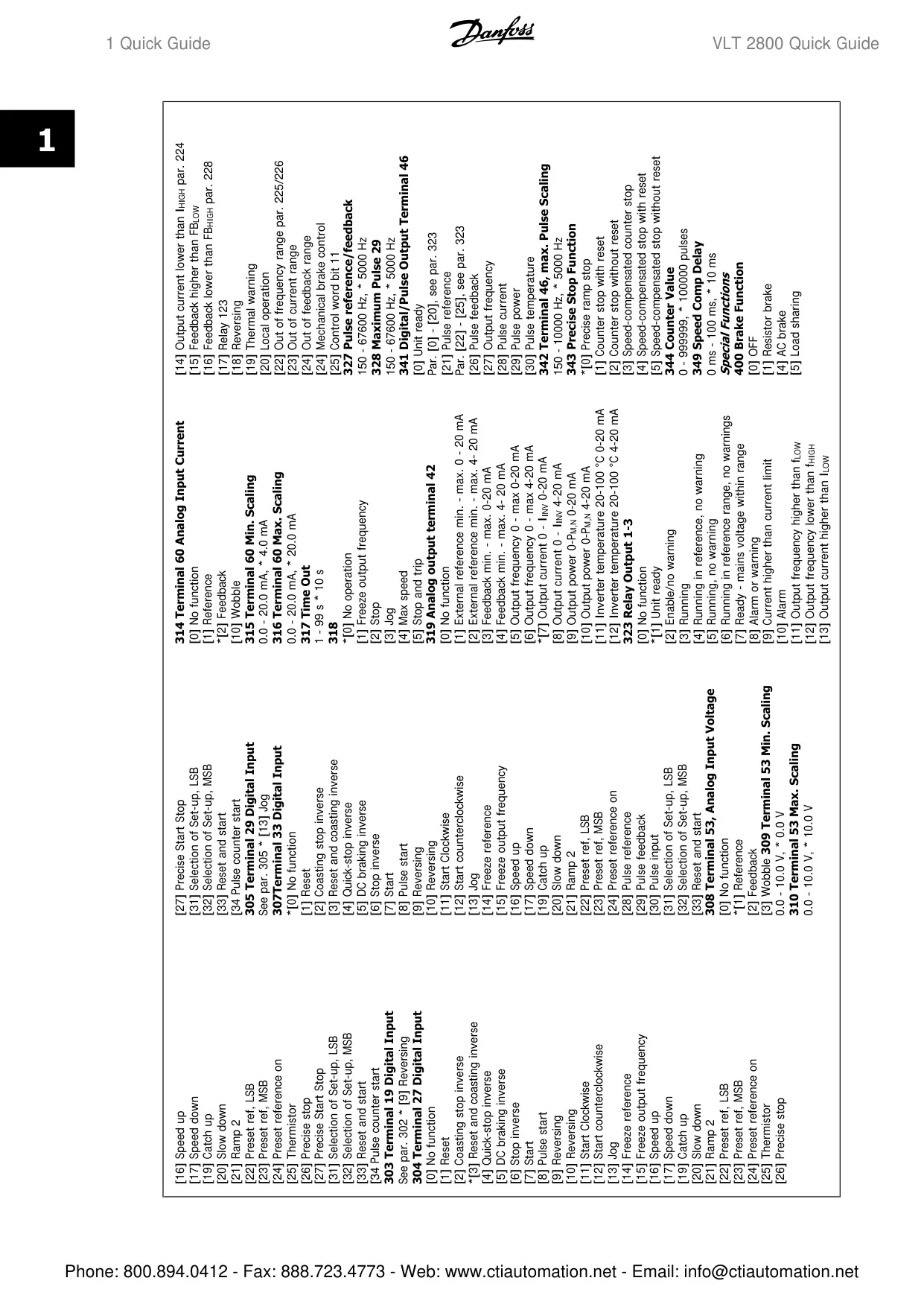
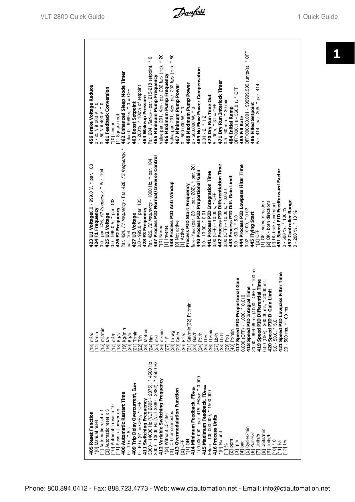
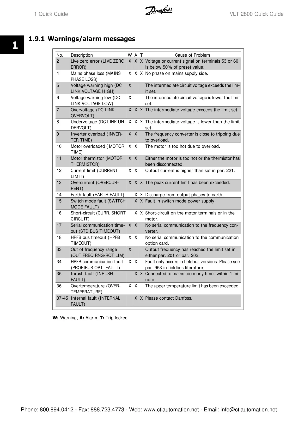
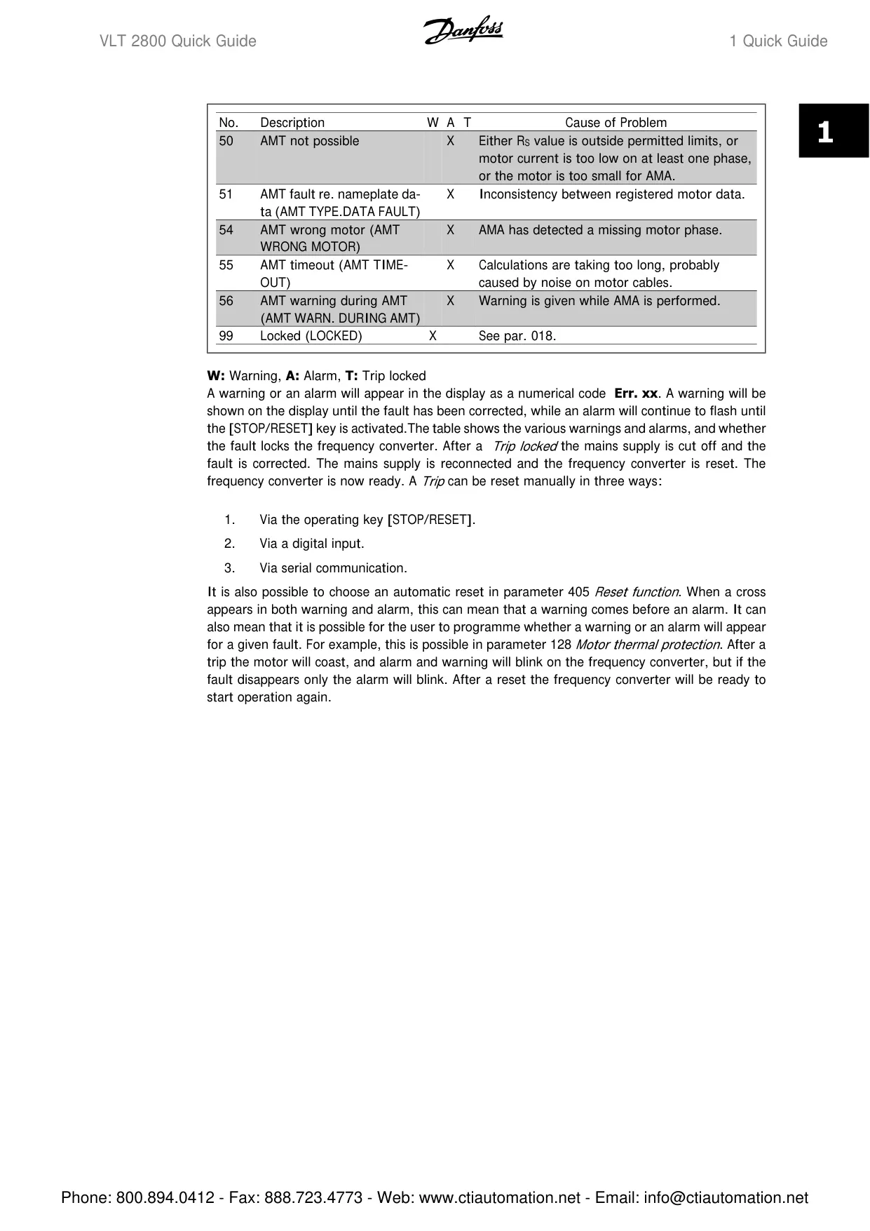
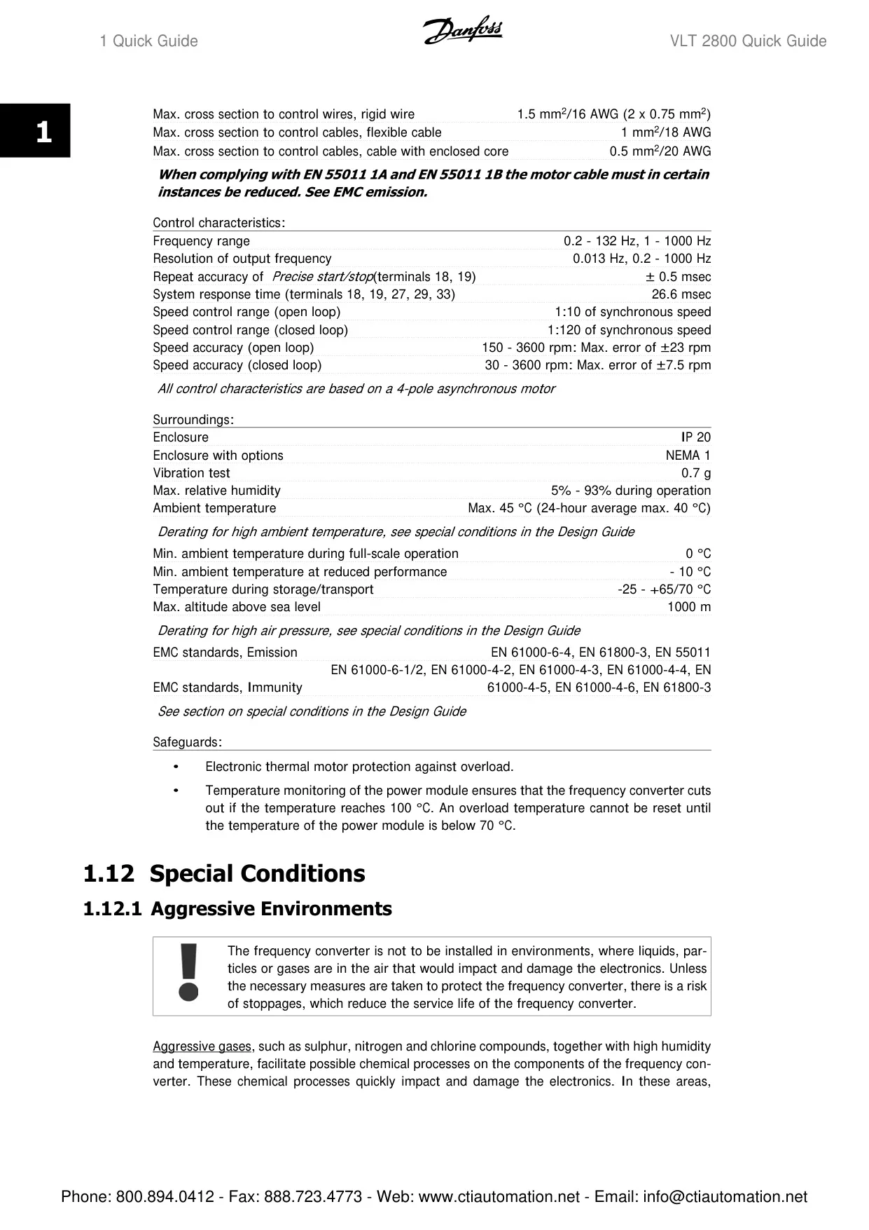
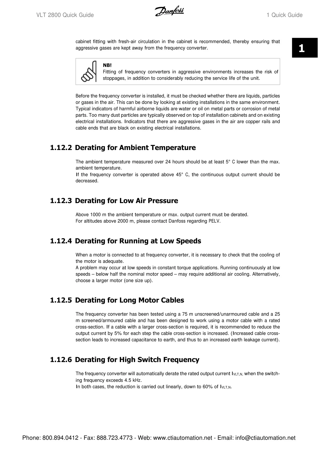
Danfoss AC Drive VLT 2800 Instructions
Here we offer the Danfoss AC Drive VLT 2800 manual completely free and in English. We have cataloged this manual in the Variable Frequency Drives section on Manualverse, and it has been rated by 1 users with an average rating of 5. If you have any specific questions about Danfoss AC Drive VLT 2800, we suggest checking the Frequently Asked Questions (FAQs) section of this manual.
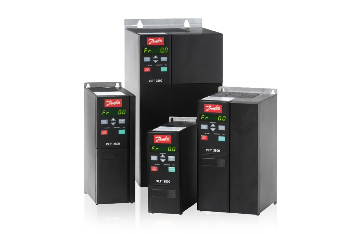
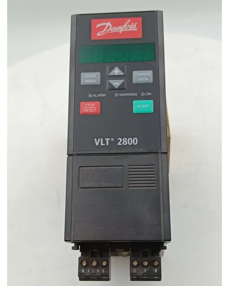
Product Images
Danfoss AC Drive VLT 2800 Specifications
| Feature | Specification |
|---|---|
| Supported Software Version | Ver. 2.6x/2.x (for VLT 2800 Profibus DP V1) |
| Baudrate Adjustment | Automatic, adjusts to master configuration |
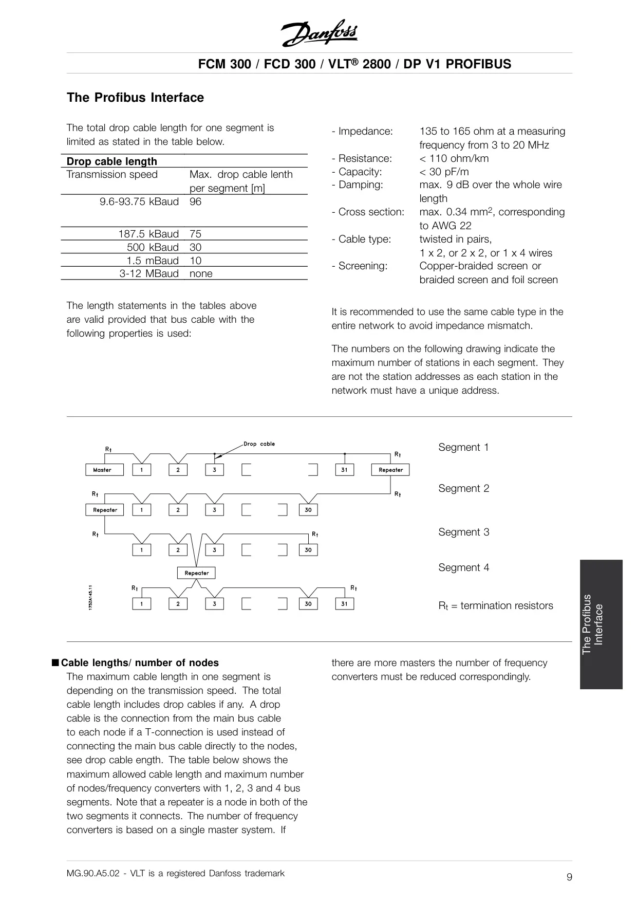
| Profibus Cable Impedance | 135 to 165 ohm (3 to 20 MHz) |
| Profibus Cable Resistance | < 110 ohm/km |
| Profibus Cable Capacity | < 30 pF/m |
| Profibus Cable Damping | Max. 9 dB (whole wire length) |
| Profibus Cable Cross Section | Max. 0.34 mm2 (AWG 22) |
| Profibus Cable Type | Twisted pairs (1x2, 2x2, or 1x4 wires), Copper-braided or braided/foil screen |
| Max. Drop Cable Length (9.6-93.75 kBaud) | 96 m per segment |
| Max. Drop Cable Length (187.5 kBaud) | 75 m per segment |
| Max. Drop Cable Length (500 kBaud) | 30 m per segment |
| Max. Drop Cable Length (1.5 MBaud) | 10 m per segment |
| Max. Drop Cable Length (3-12 MBaud) | None (direct connection recommended) |
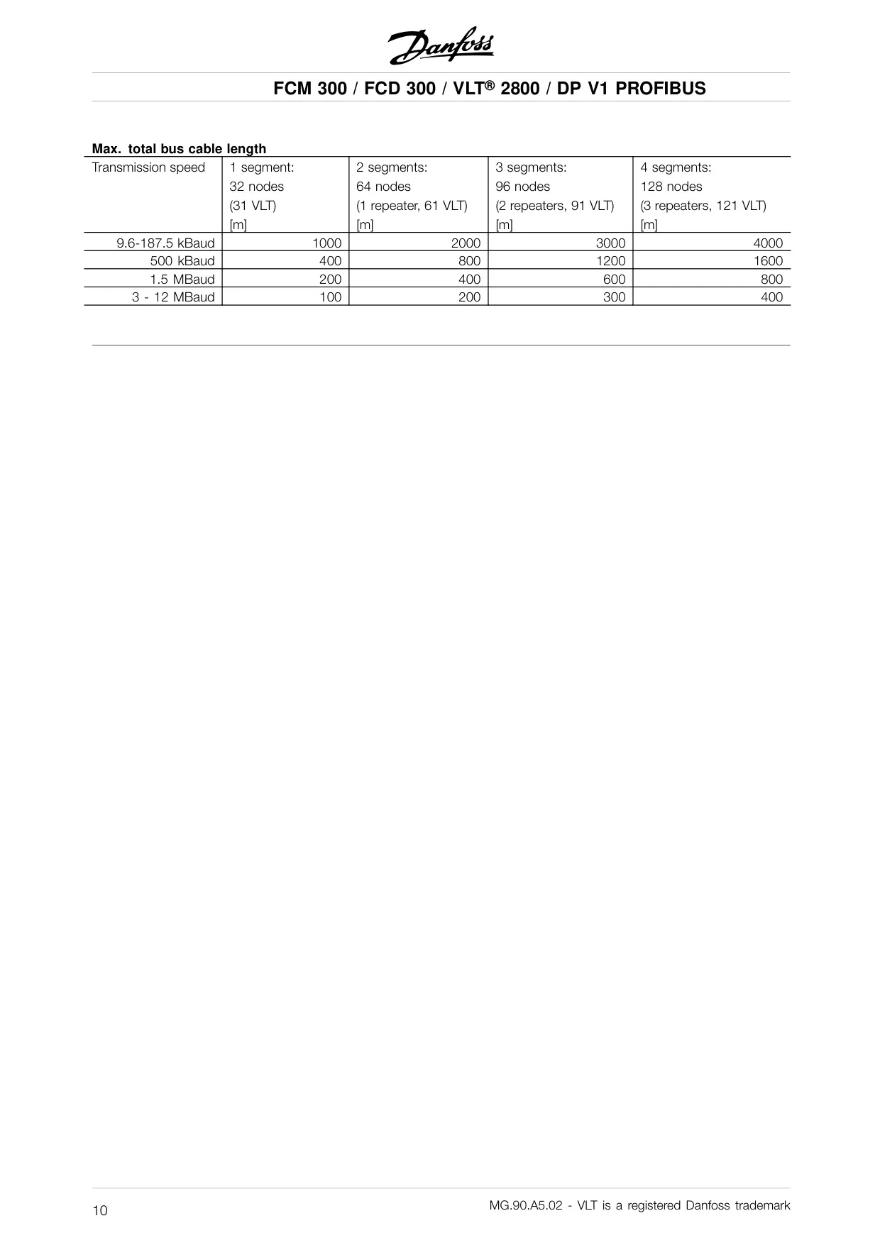
| Max. Total Bus Cable Length (1 segment, 9.6-187.5 kBaud) | 1000 m (32 nodes, 31 VLTs) |
| Max. Total Bus Cable Length (1 segment, 3-12 MBaud) | 100 m (32 nodes, 31 VLTs) |
| Control Word / Main Reference Update Time (tint) | Max. 26 msec. |
| Status Word / Actual Output Frequency Update Time (tint) | Max. 26 msec. |
| Parameter Read (PCD 1-8) Update Time (tint) | 40 msec. |
| Parameter Write (PCD 1-2) Update Time (tint) | 160 msec. |
| Parameter Read (PCV) Update Time (tint) | 41 msec. |
| Parameter Write (PCV) Update Time (tint) | 40 msec. |
| Acyclical Data (single read, write) Update Time (tint) | 40 msec. |
| Profibus DP Communication Standard | EN 50170, part 3 |
| Supported Profibus Profile | PROFIDRIVE Profile for frequency converters (version 2 and partly 3, PNO) |
Danfoss AC Drive VLT 2800 Details
The Danfoss AC Drive VLT 2800, when equipped with a PROFIBUS interface, functions as a sophisticated slave in a fieldbus network, communicating with masters like PLCs or PCs. This setup grants comprehensive control and monitoring capabilities, enabling the exchange of various information and commands. It adheres to the PROFIBUS fieldbus standard EN 50170, part 3, facilitating interoperability with compliant masters.
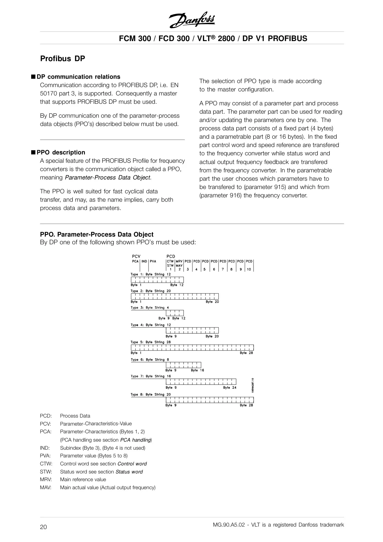
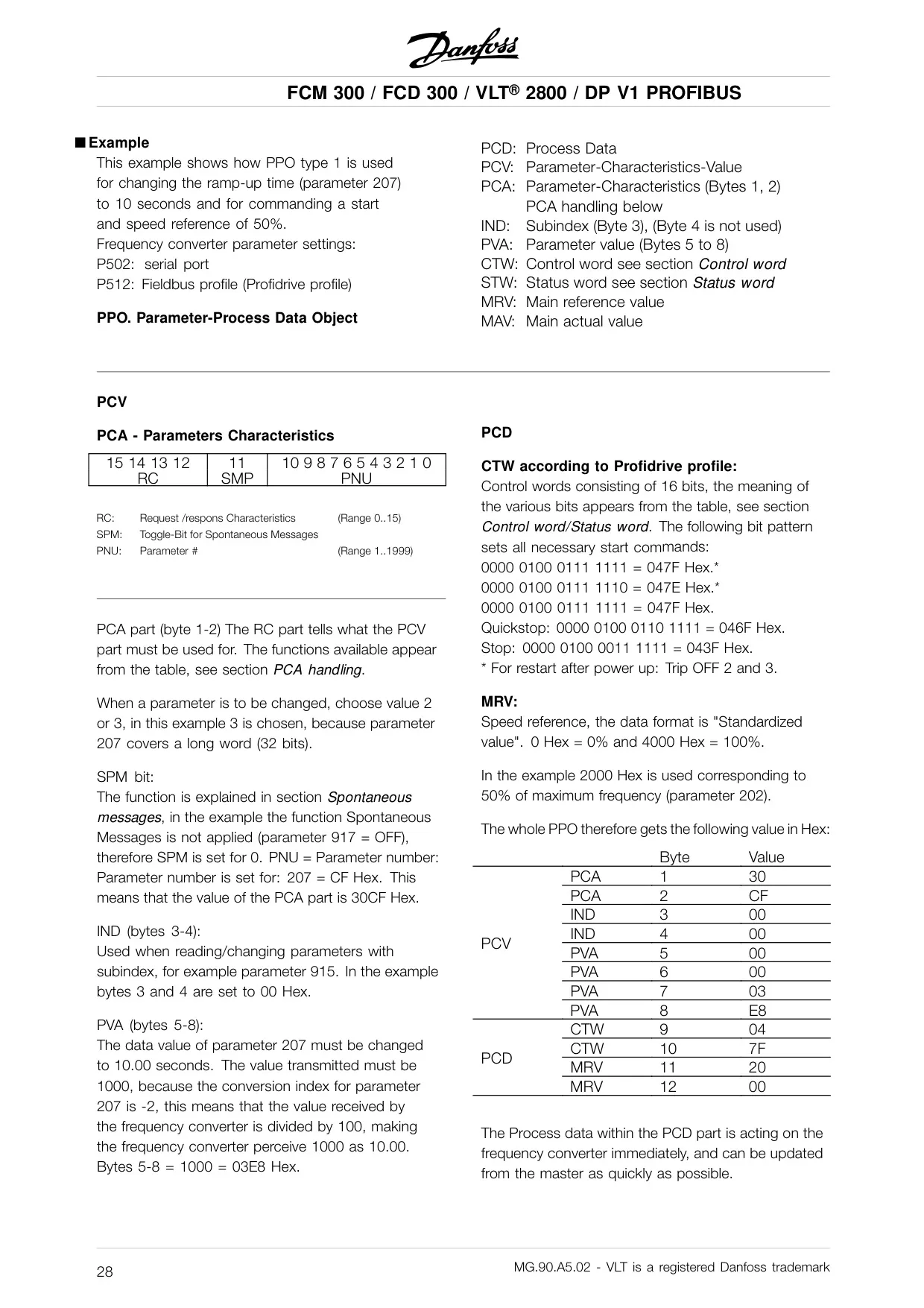
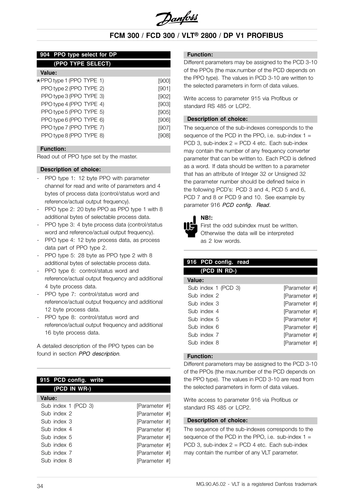
A core feature is the use of Parameter-Process Data Objects (PPOs), which are optimized for rapid cyclical data transfer. PPOs can carry both process data, such as control words and speed references, and parameters for configuration. Different PPO types offer flexibility in data size and content, supporting fixed 4-byte process data alongside parametrable parts of 8 or 16 bytes for user-selected parameters.
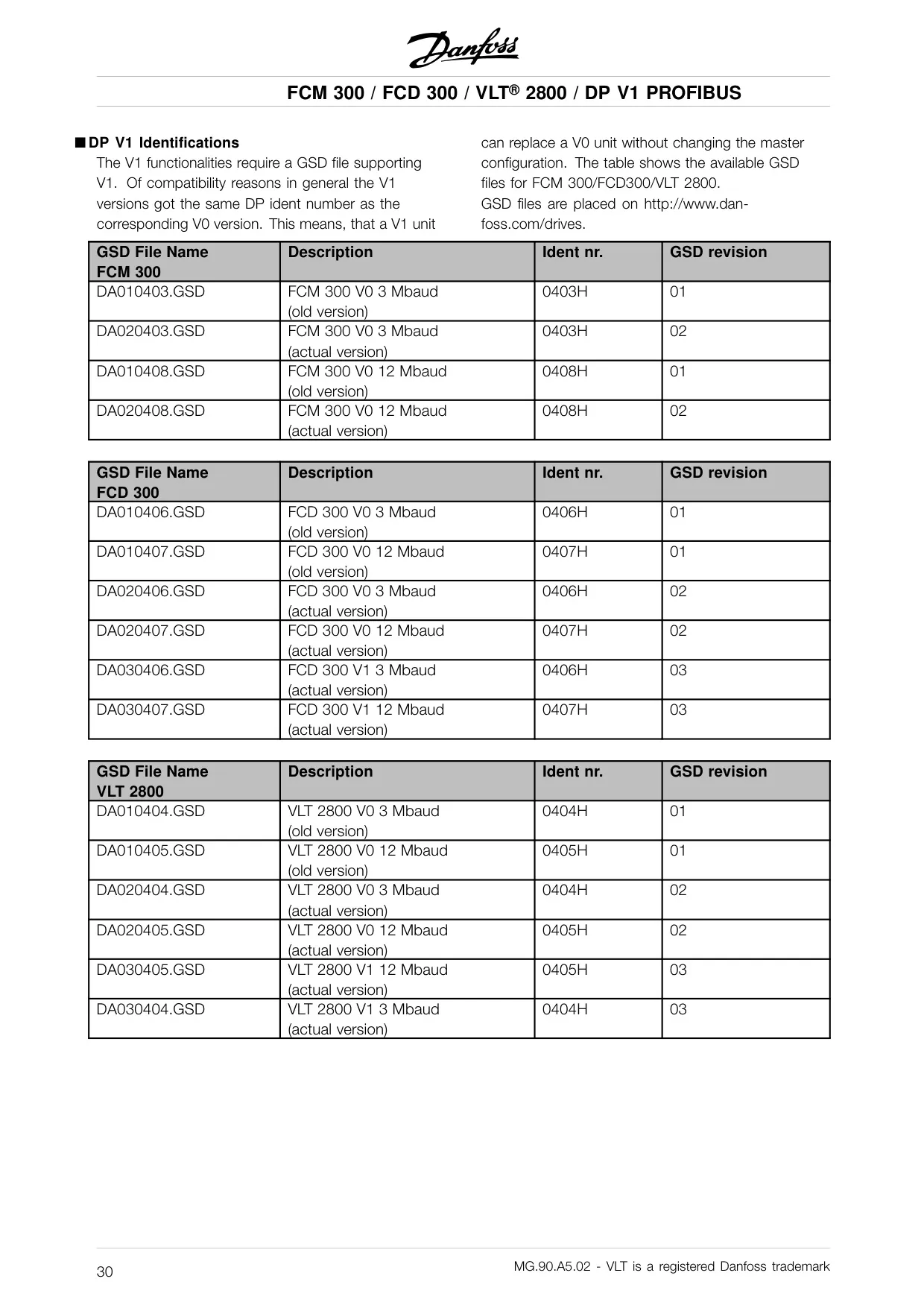
The system supports both Profibus DP V0 and the extended DP V1 functionalities. While DP V0 primarily handles cyclical data exchange, DP V1 introduces acyclical communication. This allows a Master type 1 (e.g., PLC) to perform acyclical read/write operations on parameters in addition to cyclical data. A Master type 2 (e.g., PC tool) can dynamically establish or abort acyclical connections, even when a Master type 1 is active.
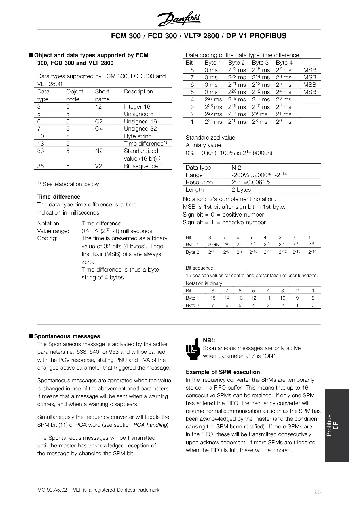
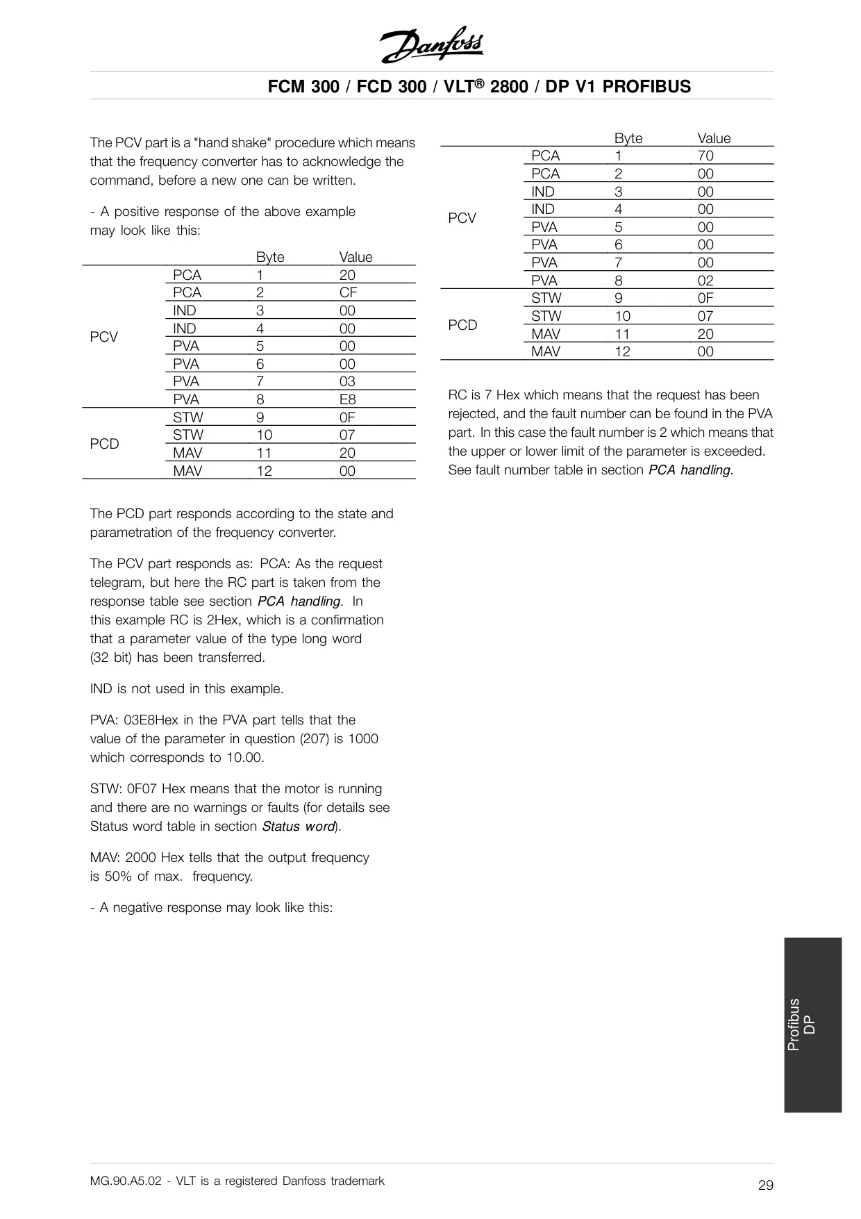
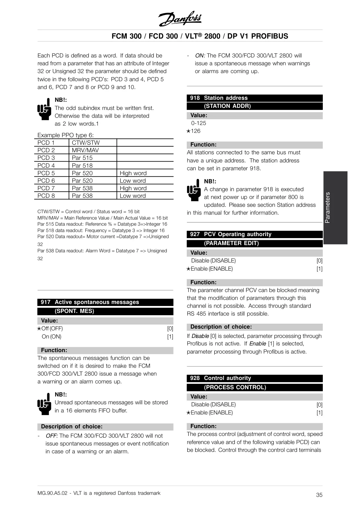
PCA handling, part of the PPO, enables the master to control and supervise parameters, request responses, and receive spontaneous messages from the slave. Requests and responses operate on a handshake basis, ensuring data integrity. The slave can transmit spontaneous messages when active parameters change, like warnings or alarms, provided parameter 917 (Spontaneous messages) is active. Fault codes are also communicated through this mechanism, detailing reasons for rejected requests.
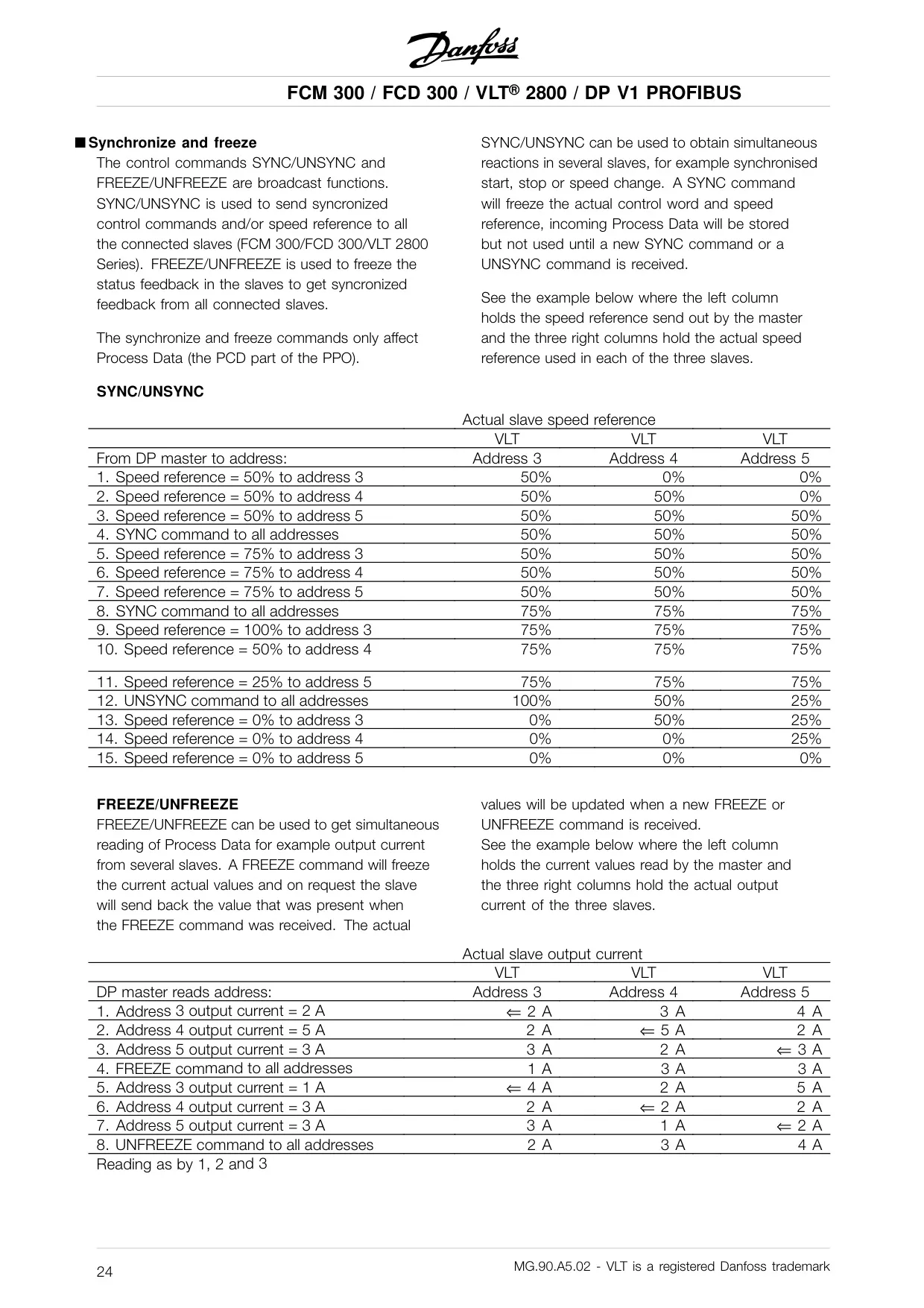
Another powerful feature includes the Synchronize and Freeze functions, designed for coordinated control and feedback in multi-slave systems. SYNC/UNSYNC commands facilitate simultaneous reactions like synchronized starts or speed changes across multiple drives. FREEZE/UNFREEZE commands allow for simultaneous readings of process data, ensuring synchronized feedback from all connected slaves. This is crucial for applications requiring tight coordination.
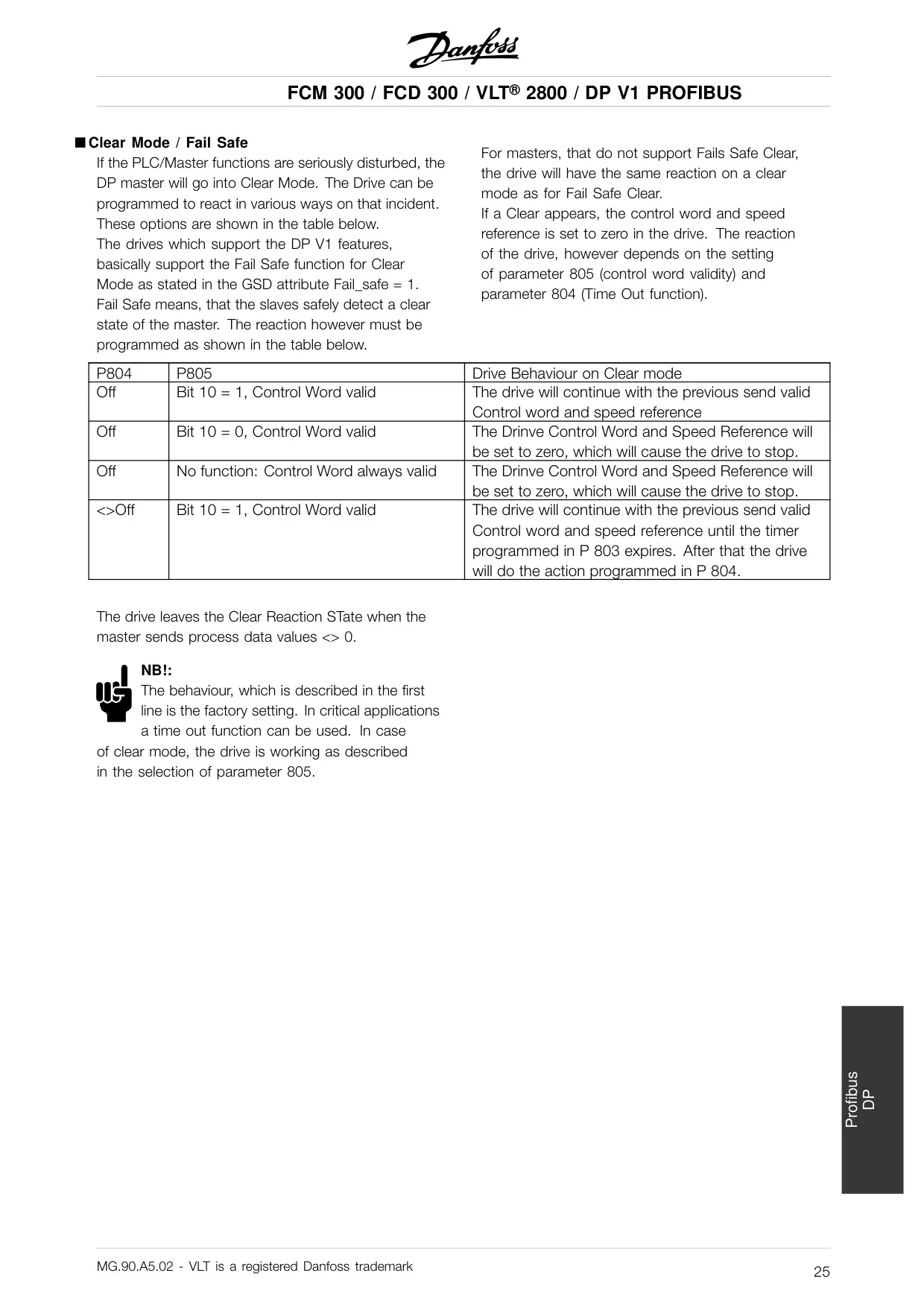
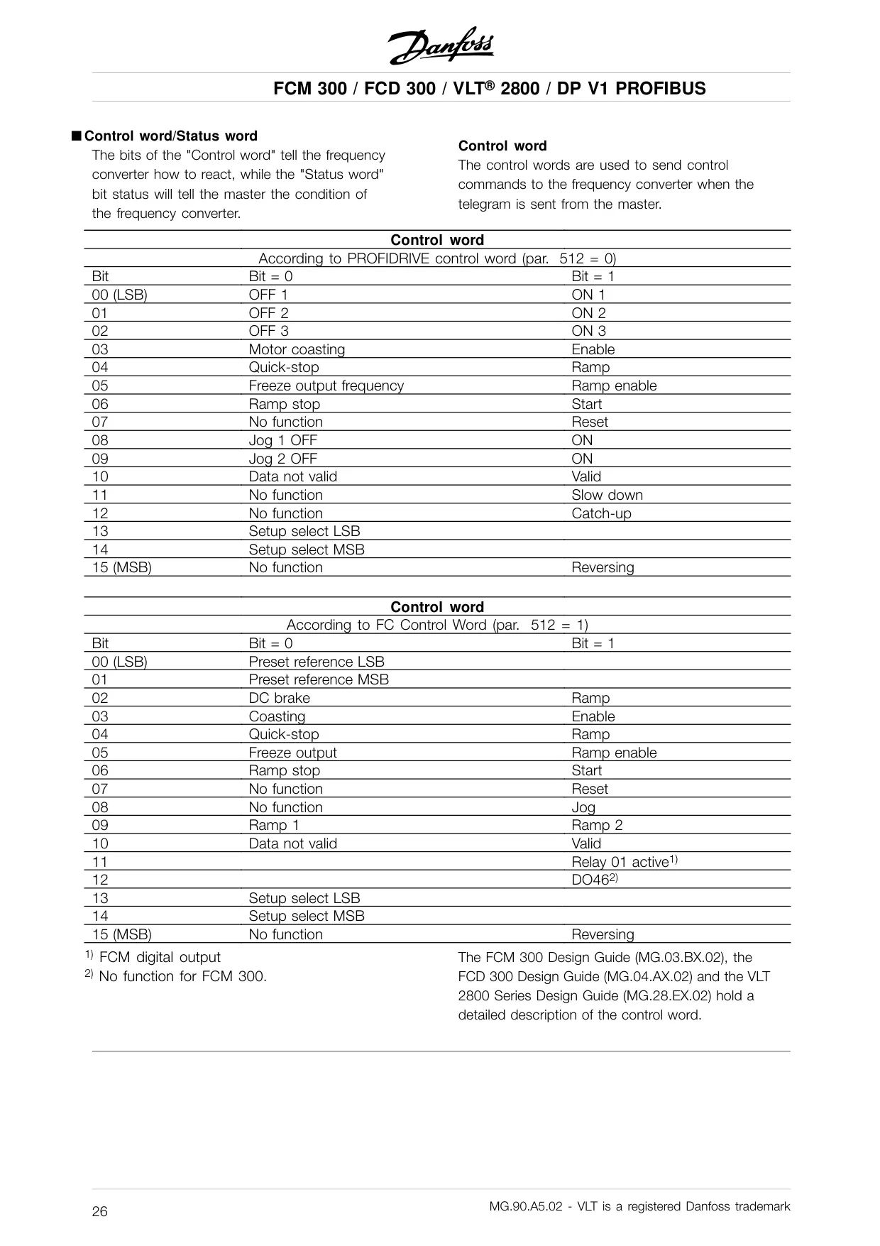
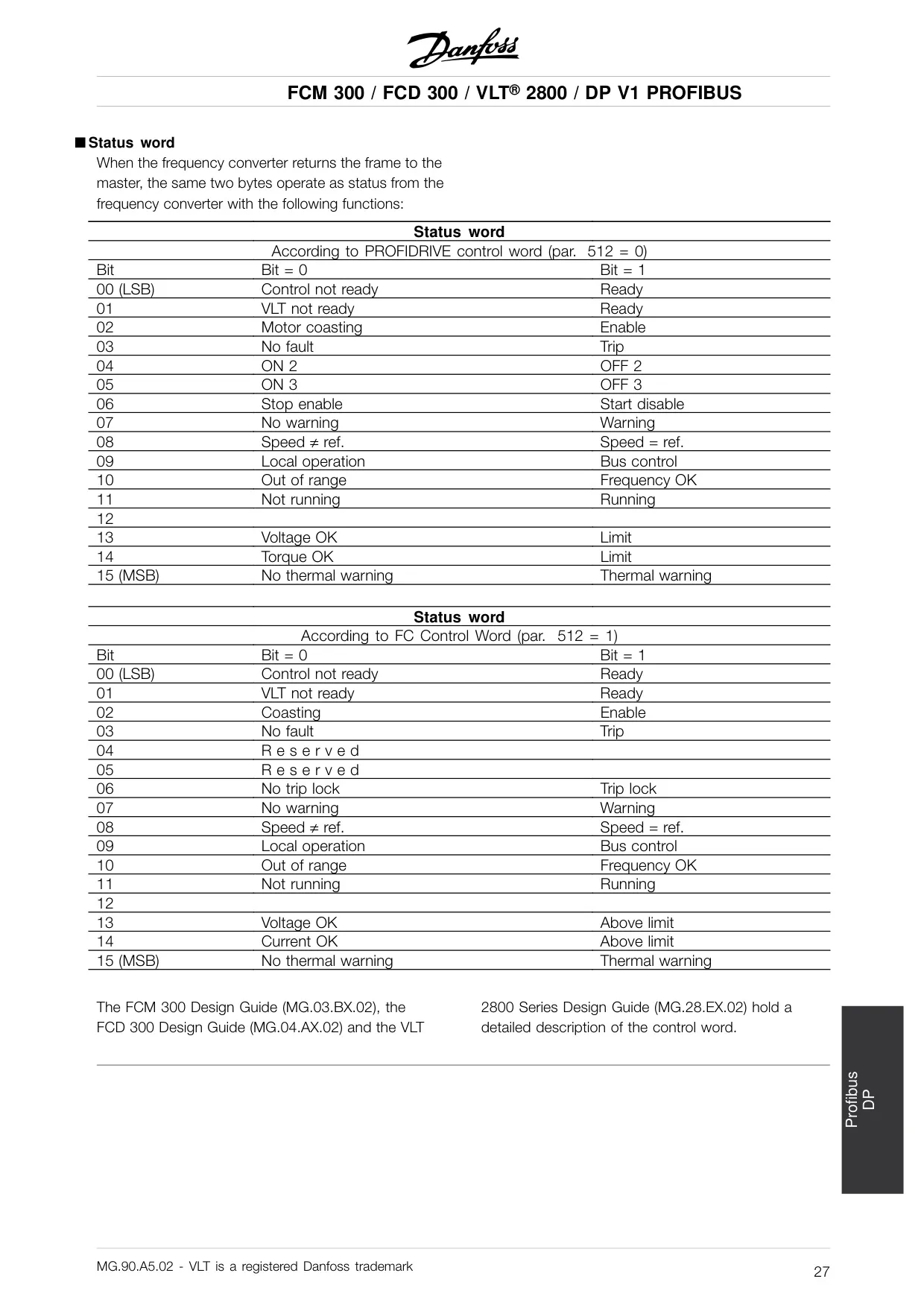
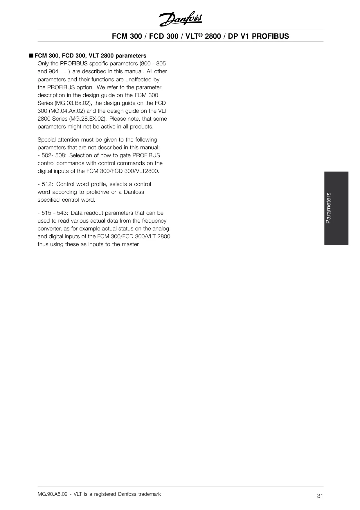
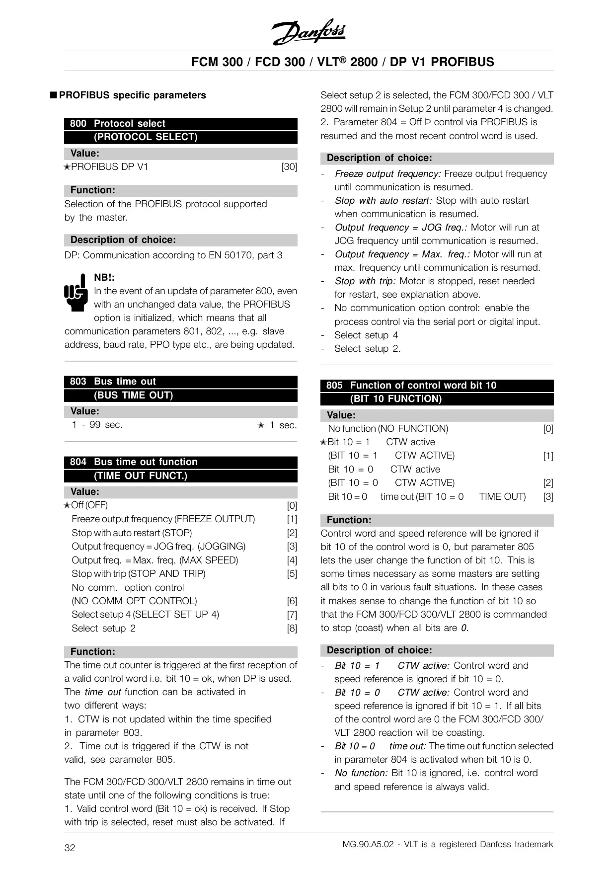
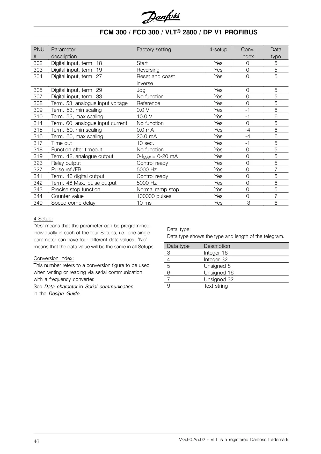
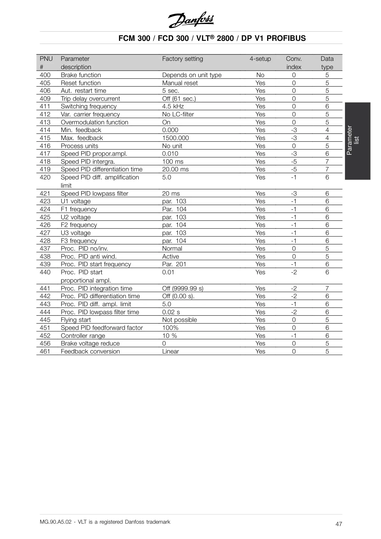
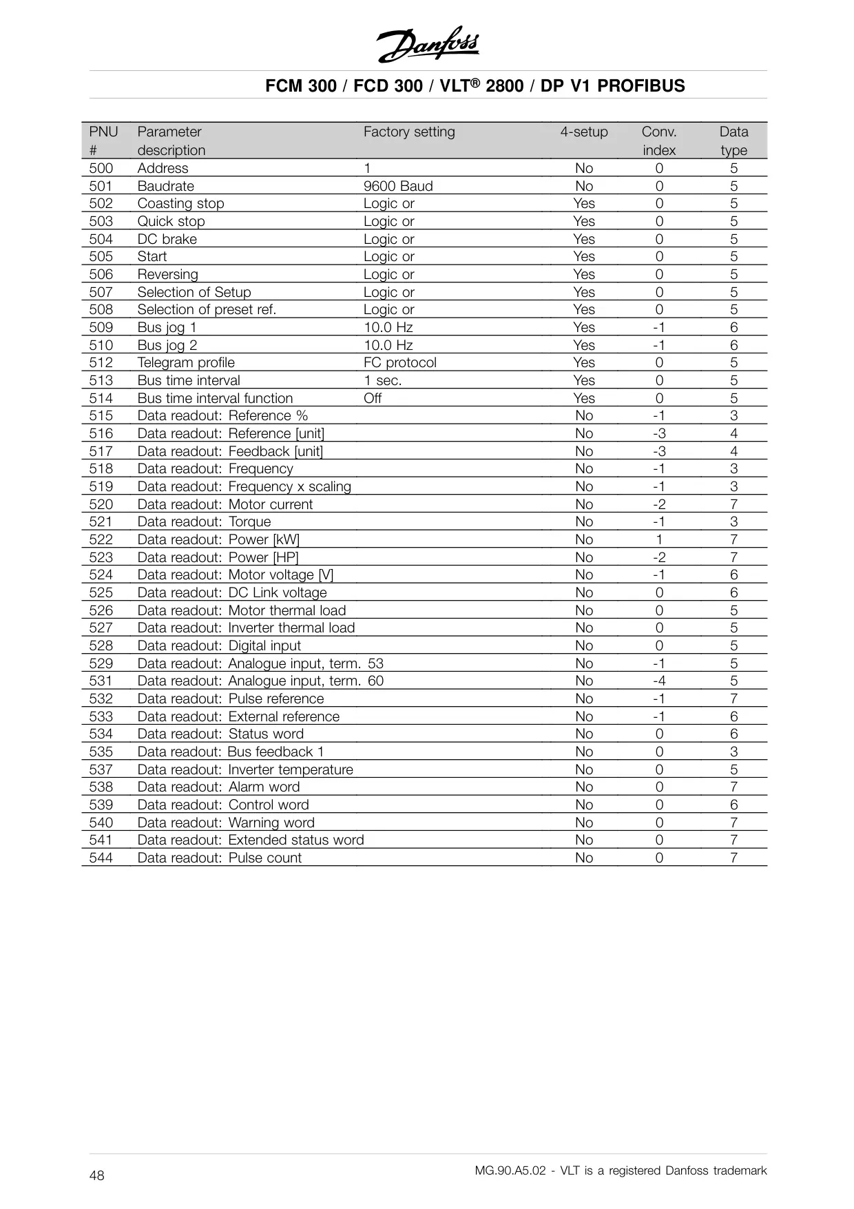
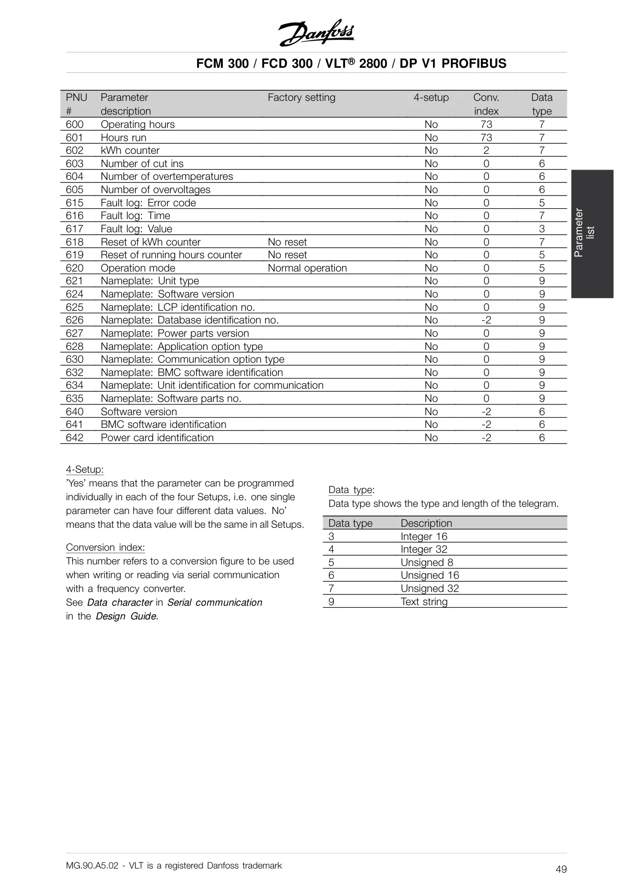
The manual also details crucial operational parameters, such as Protocol select (800) for defining the PROFIBUS protocol, and Bus time out (803/804), which dictates the drive's behavior if communication is lost. Options range from freezing the output frequency to triggering a trip. The Control Word (CTW) and Status Word (STW) are central to control, with selectable profiles (PROFIDRIVE or Danfoss FC). These 16-bit words define commands to the drive and feedback on its operational status, respectively.
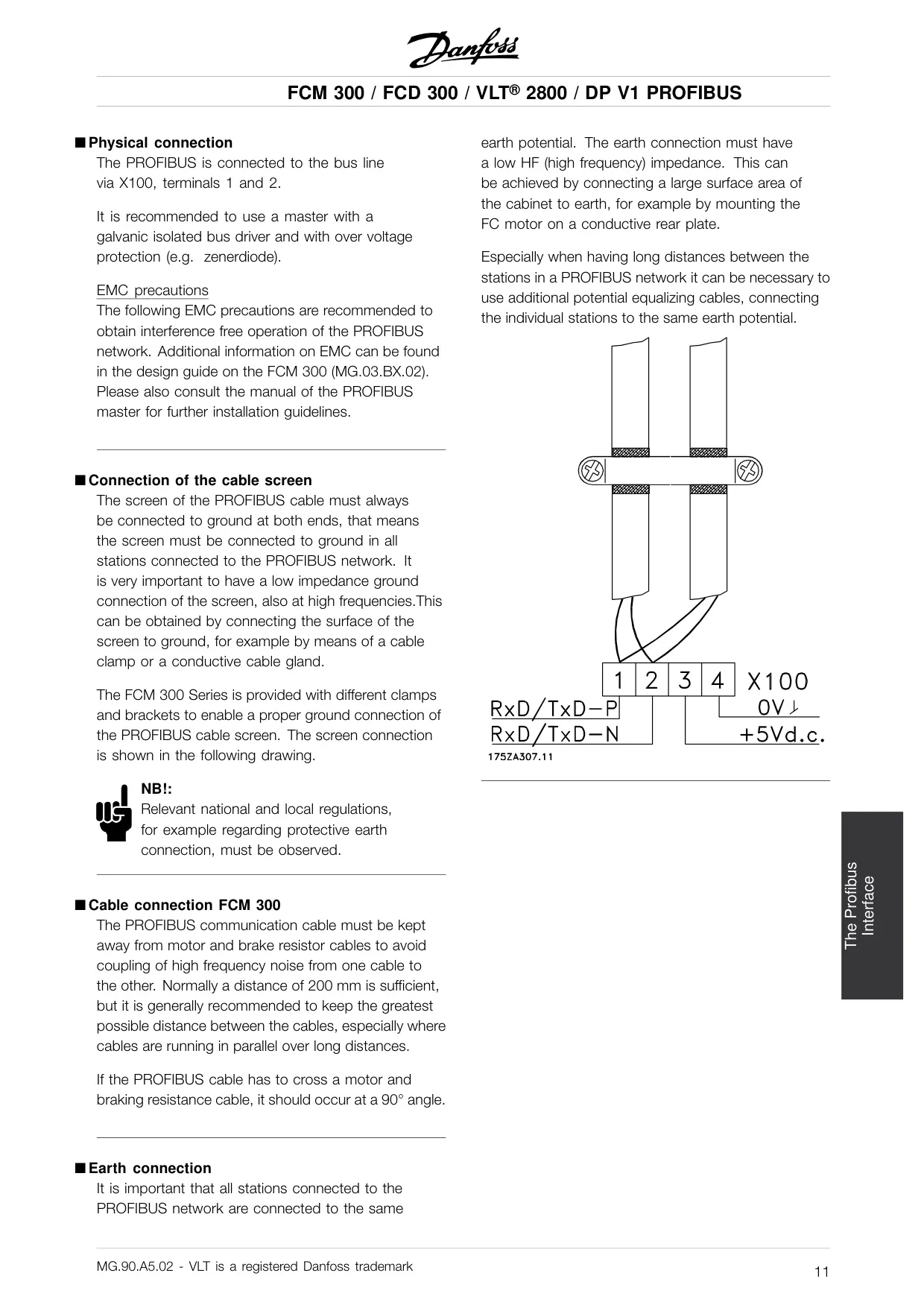
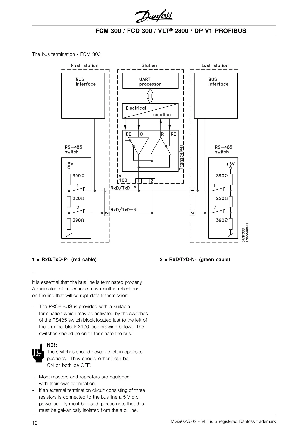
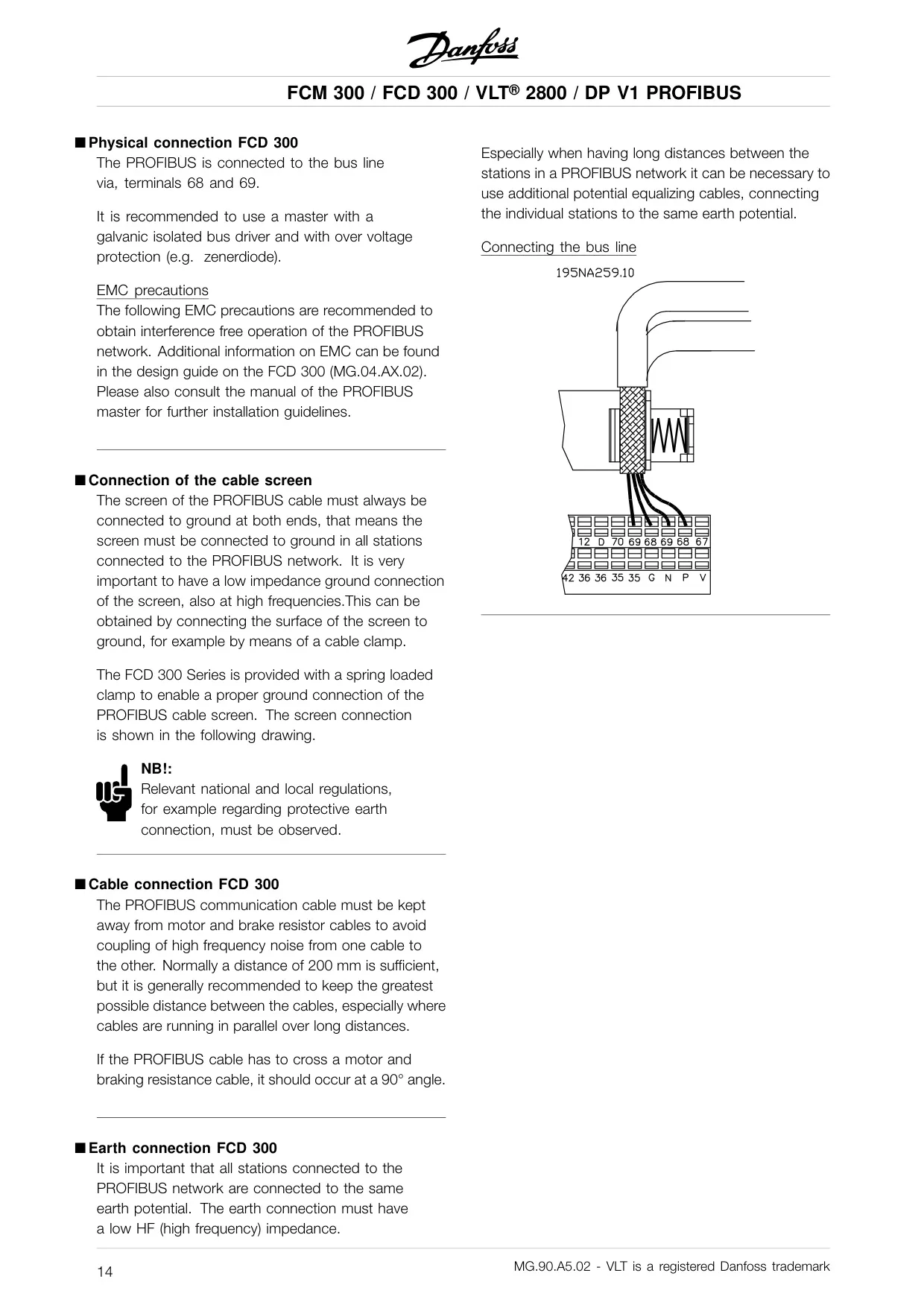
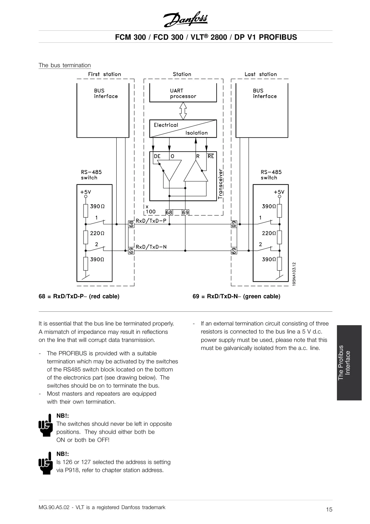
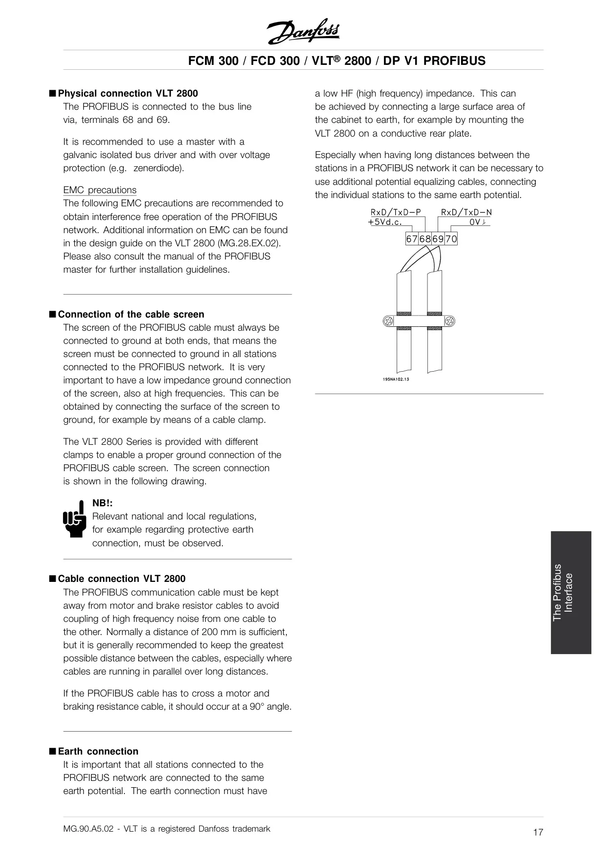
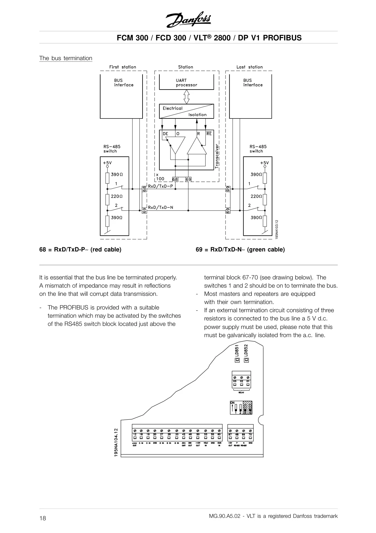
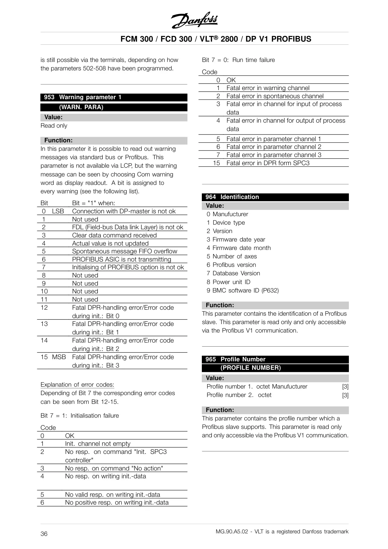
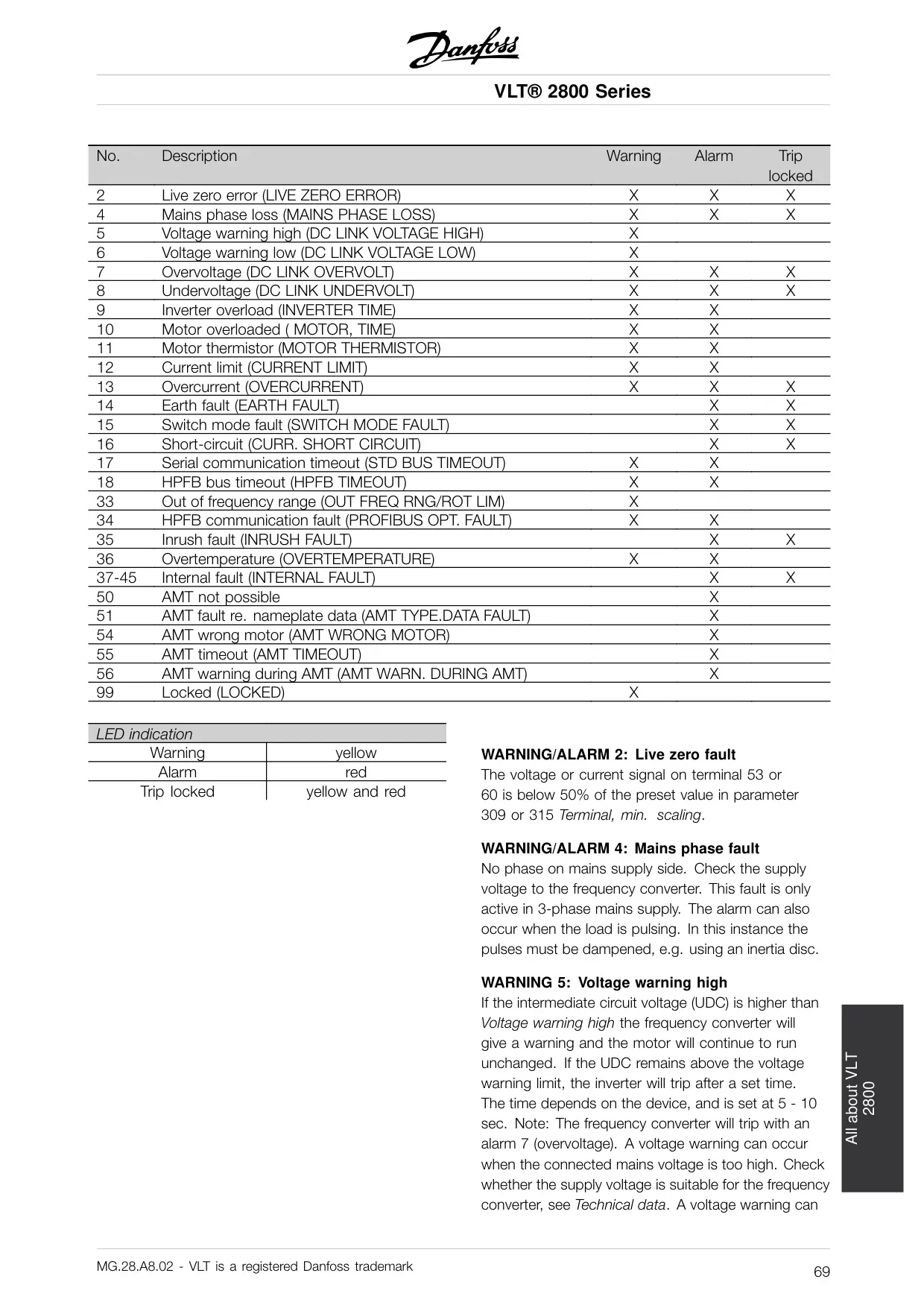
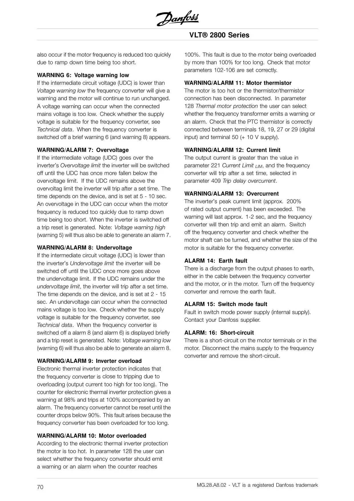
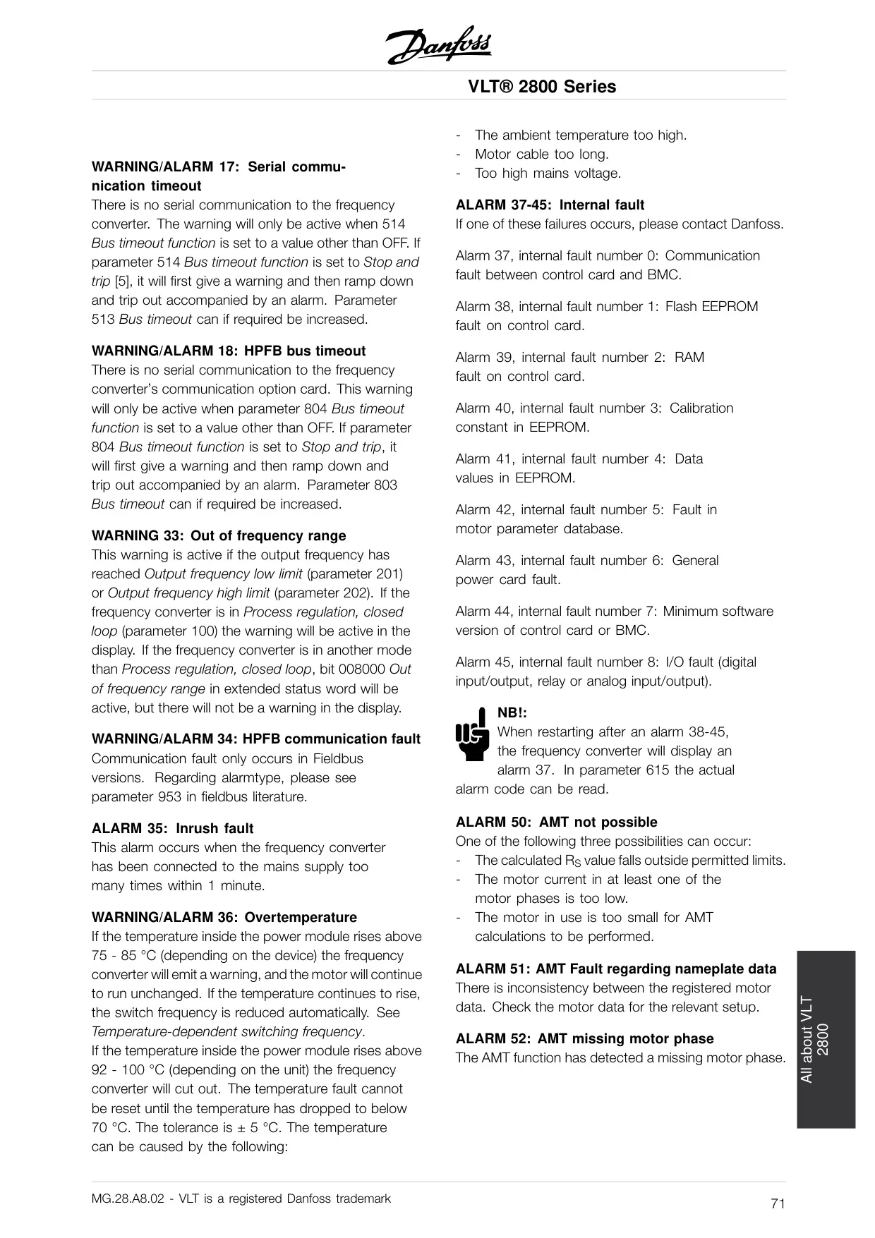
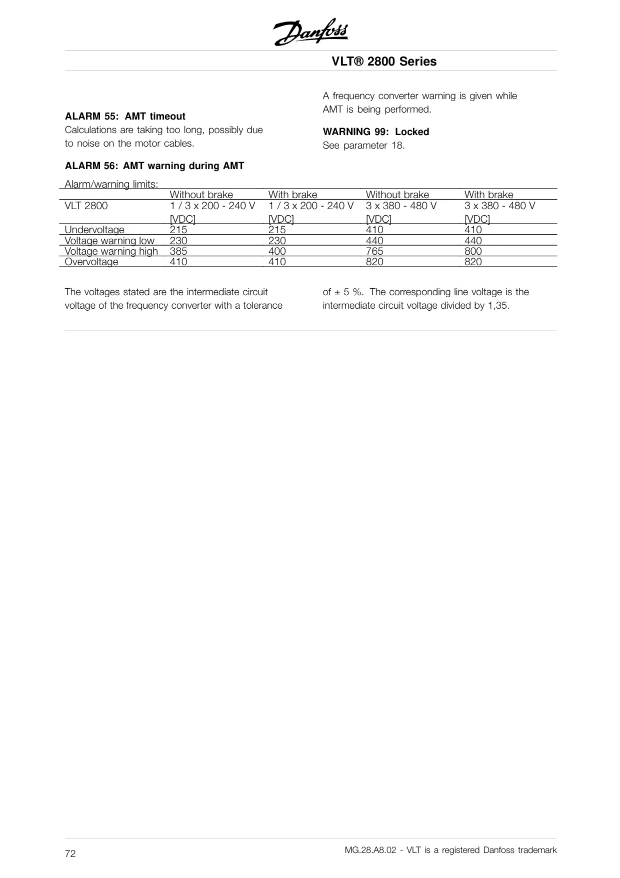
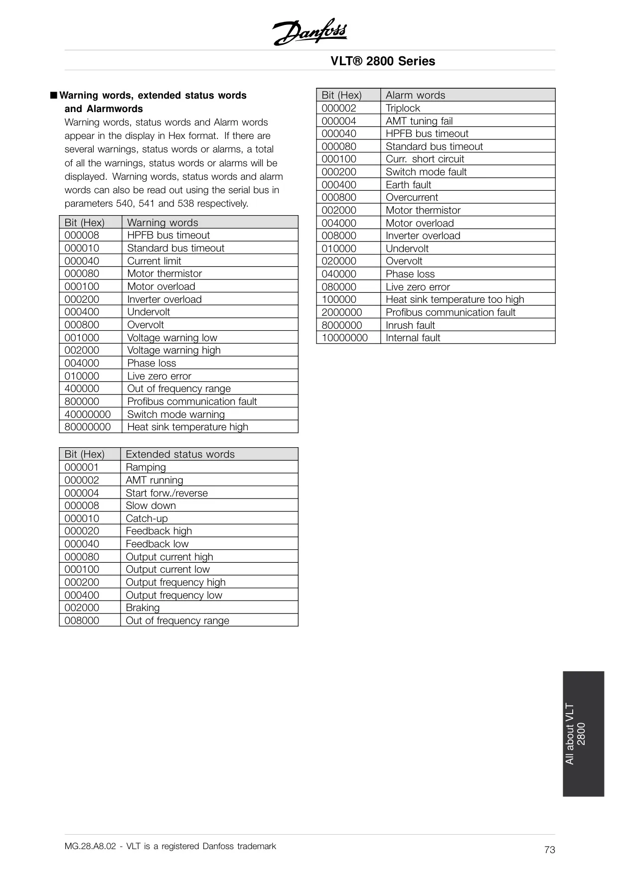
Warning and alarm messages are distinctly handled. Alarms cause the VLT 2800 to enter a fault condition requiring master acknowledgment and fault clearance before resuming operation. Warnings, conversely, indicate conditions without interrupting the process. Both can trigger spontaneous messages. Physical connection guidelines, including cable connection, screen grounding, and bus termination, are critical for EMC compliance and reliable communication.
Frequently Asked Questions (FAQs)
Can't find the answer you need? Here are some frequently asked questions about the Danfoss AC Drive VLT 2800, and we answer them below.