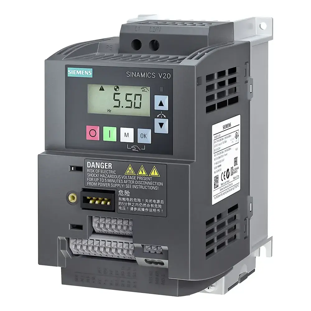
Siemens Micromaster 440 Variable Frequency Drive Instruction Manual

Siemens Micromaster 440 Variable Frequency Drive Instruction Manual
Siemens Micromaster 440 Variable Frequency Drive

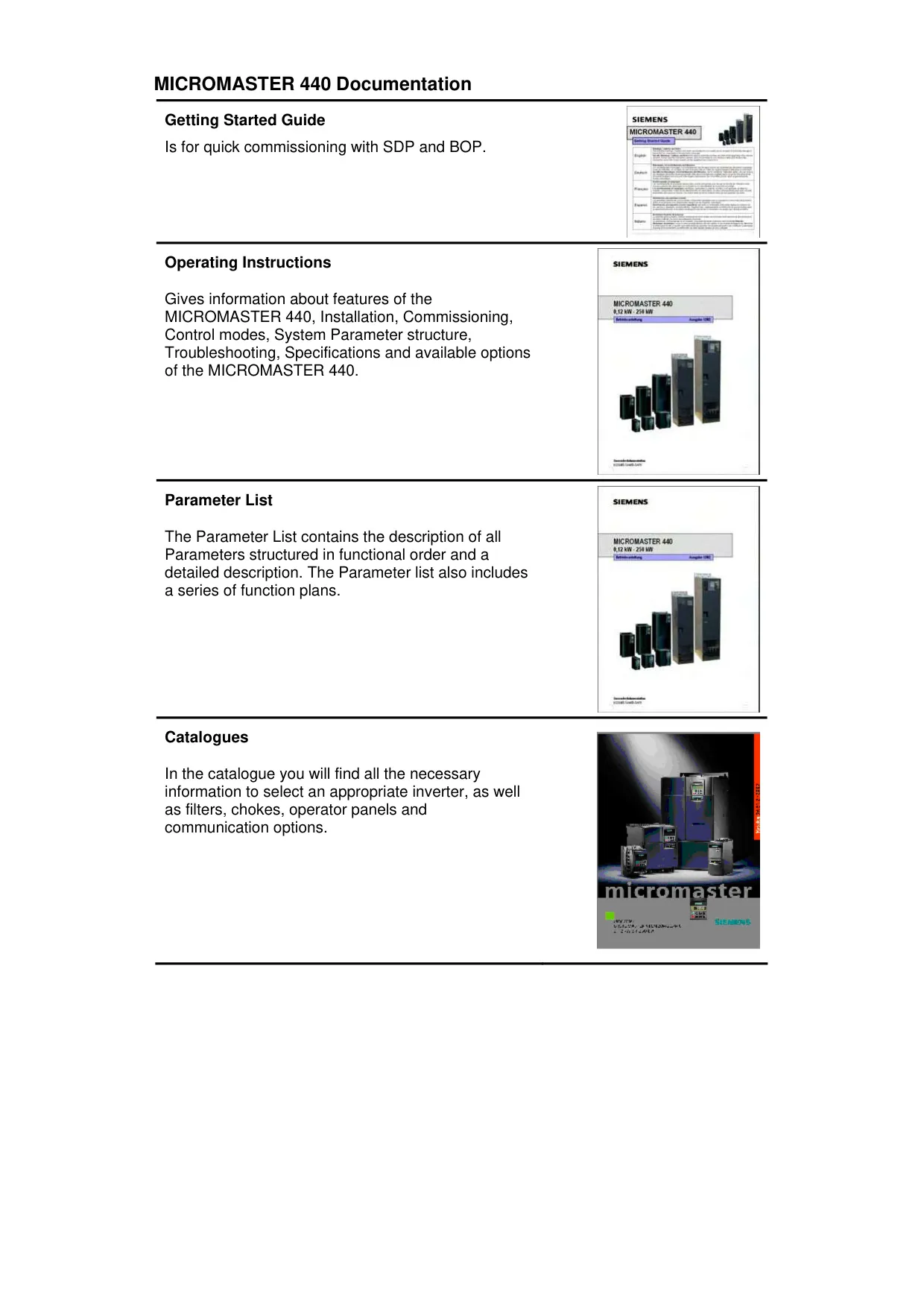


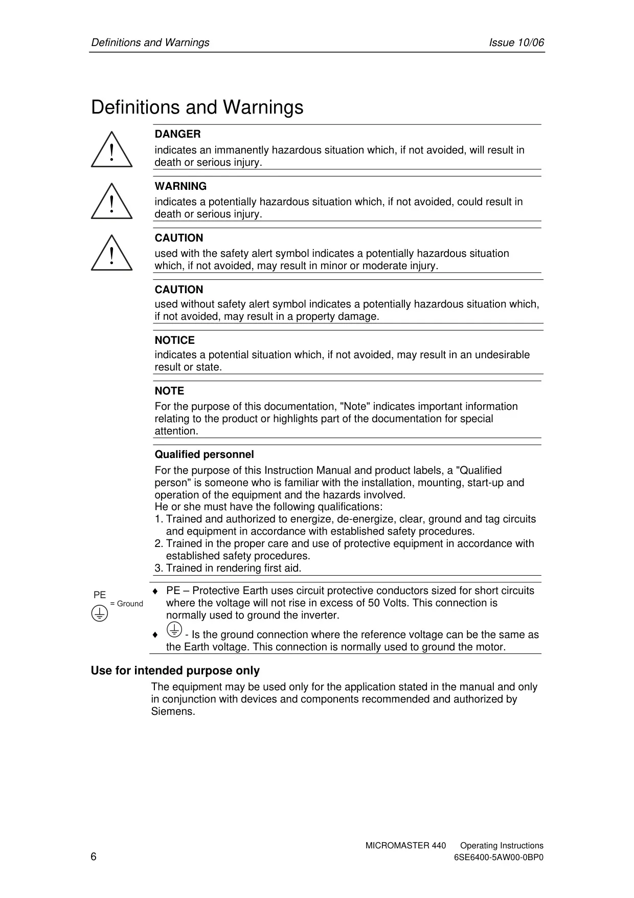





























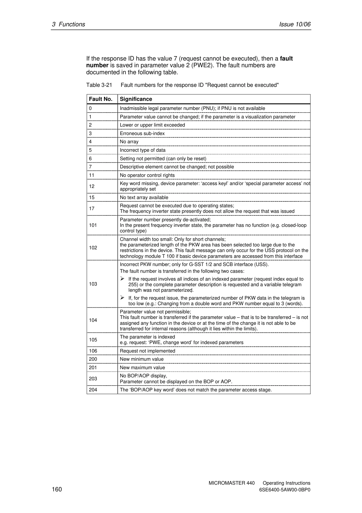

































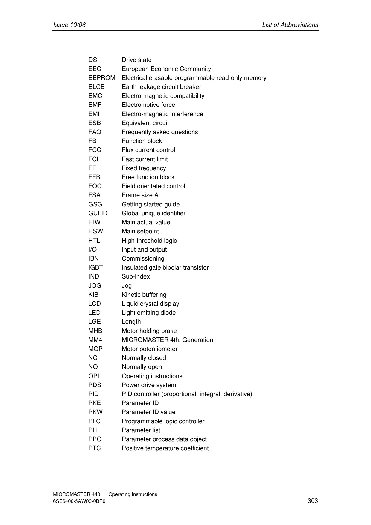




Siemens Micromaster 440 Variable Frequency Drive


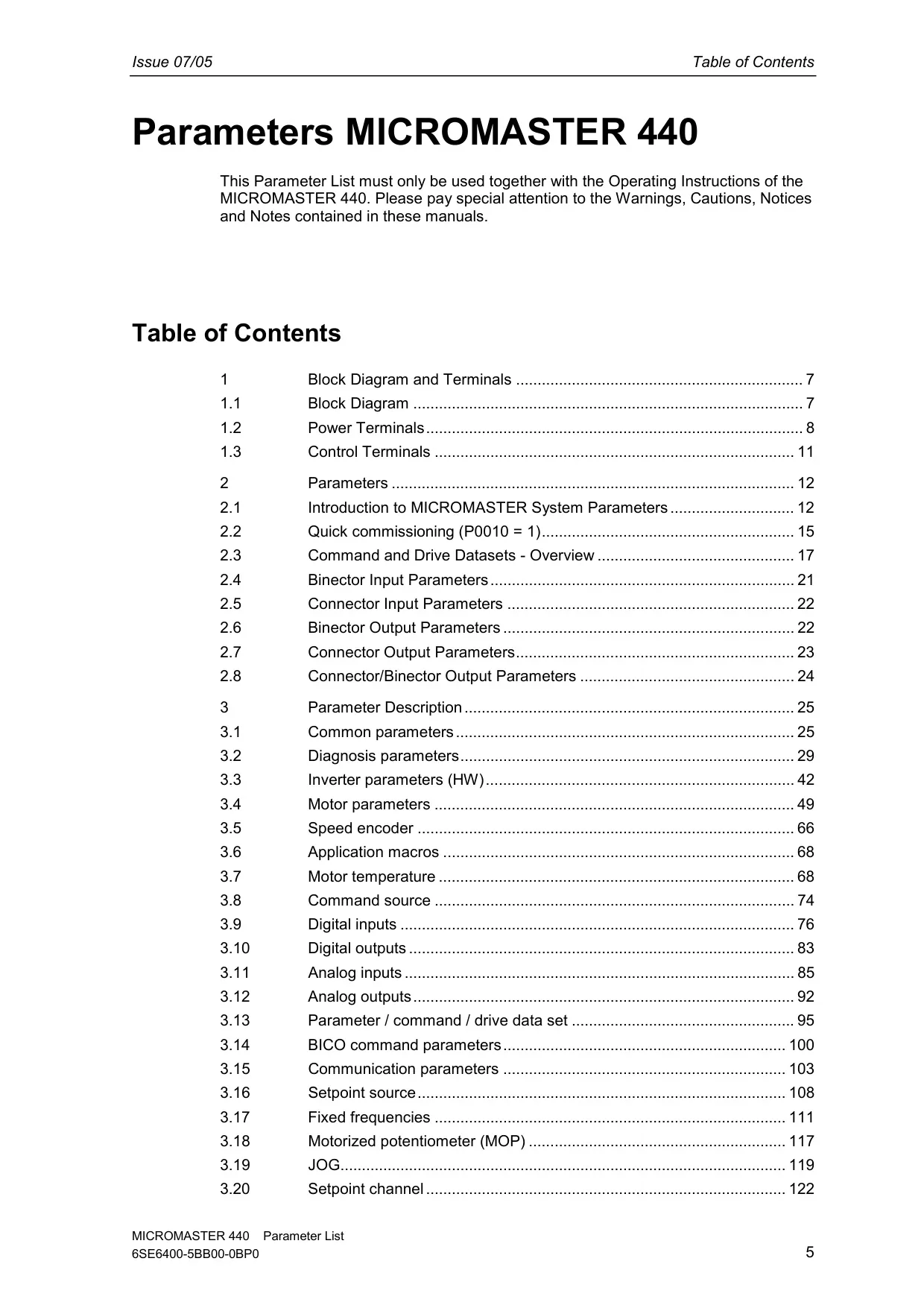


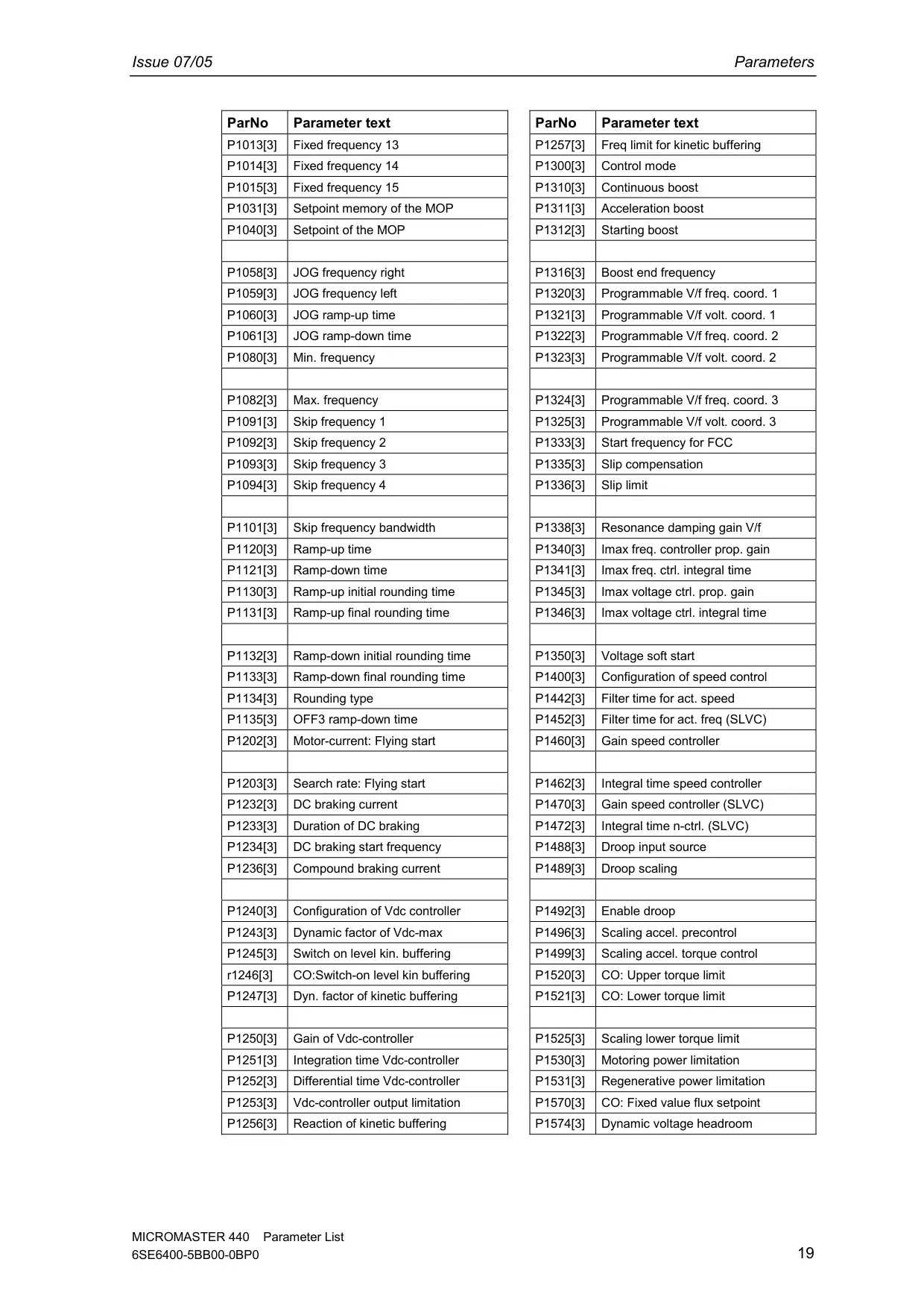


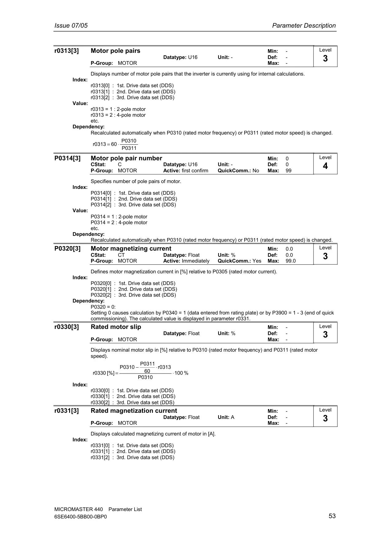


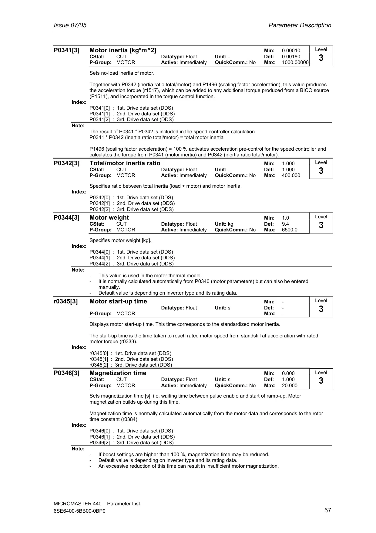


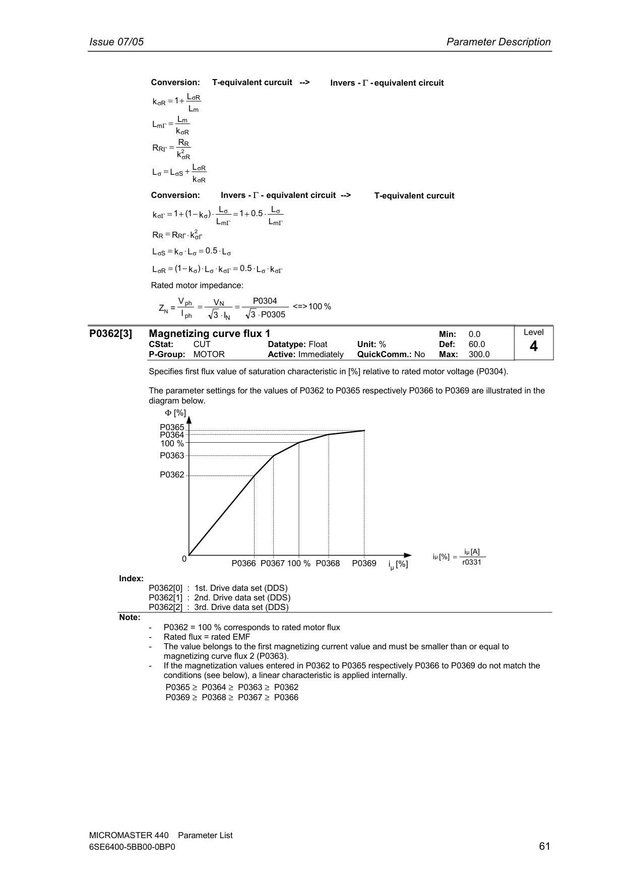


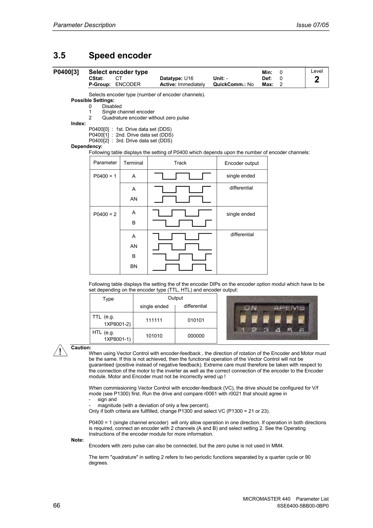


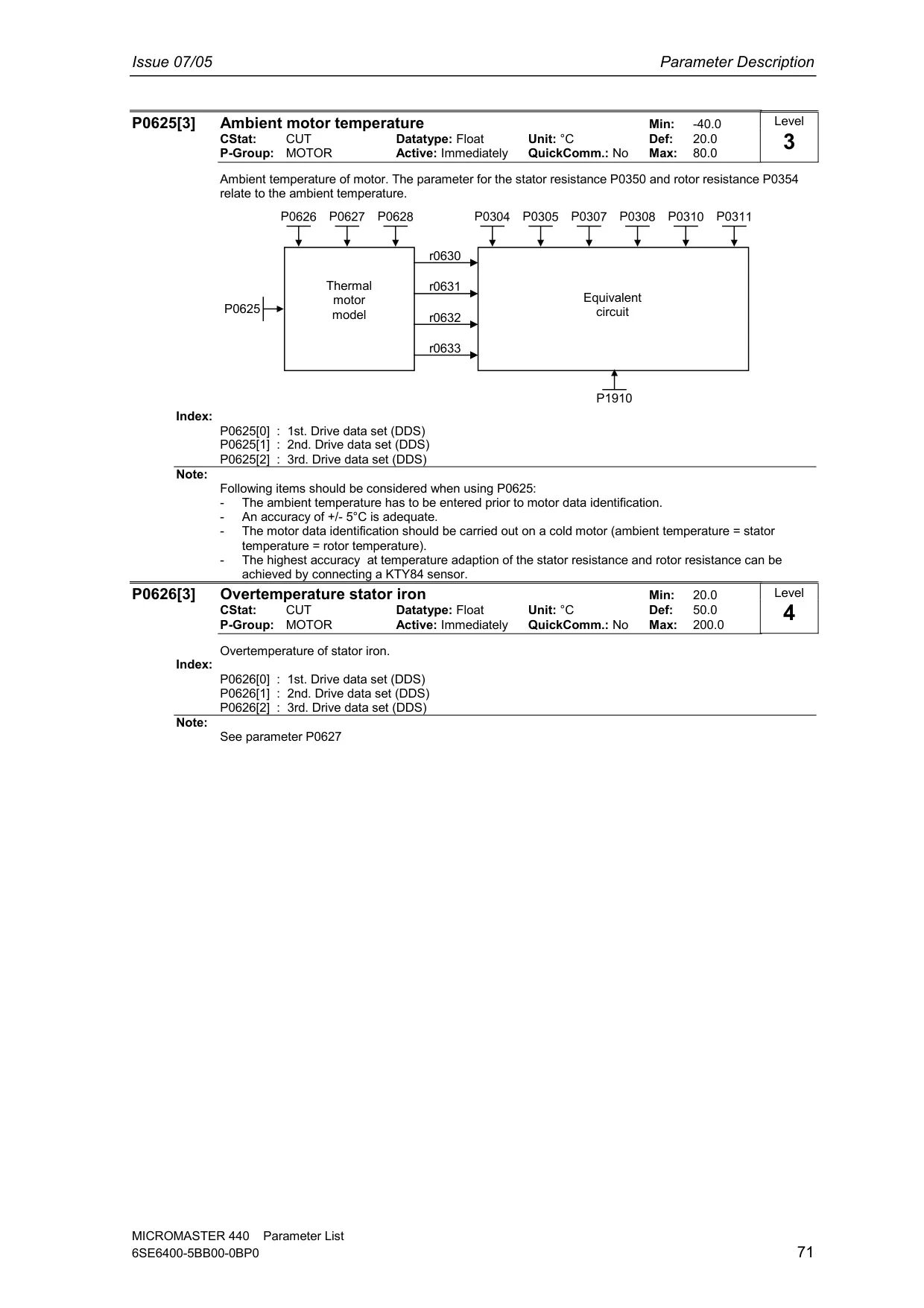



















































Siemens Micromaster 440 Variable Frequency Drive



















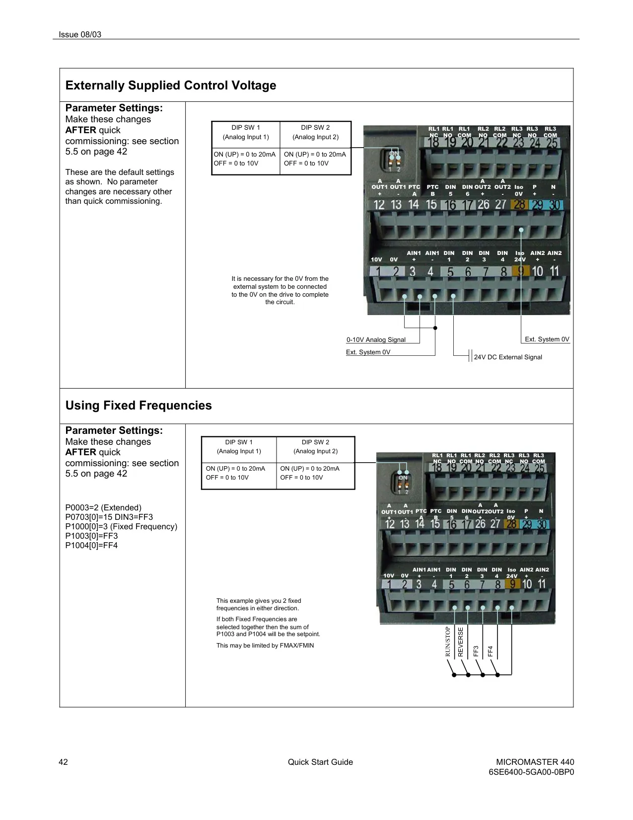
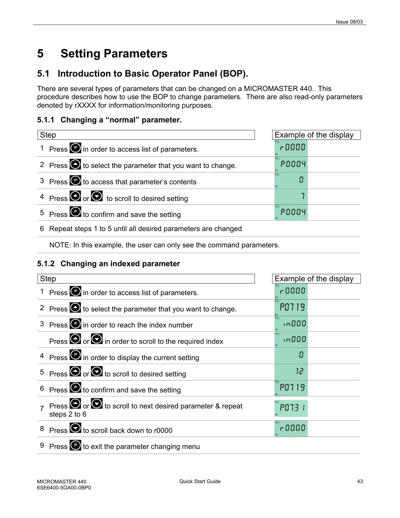
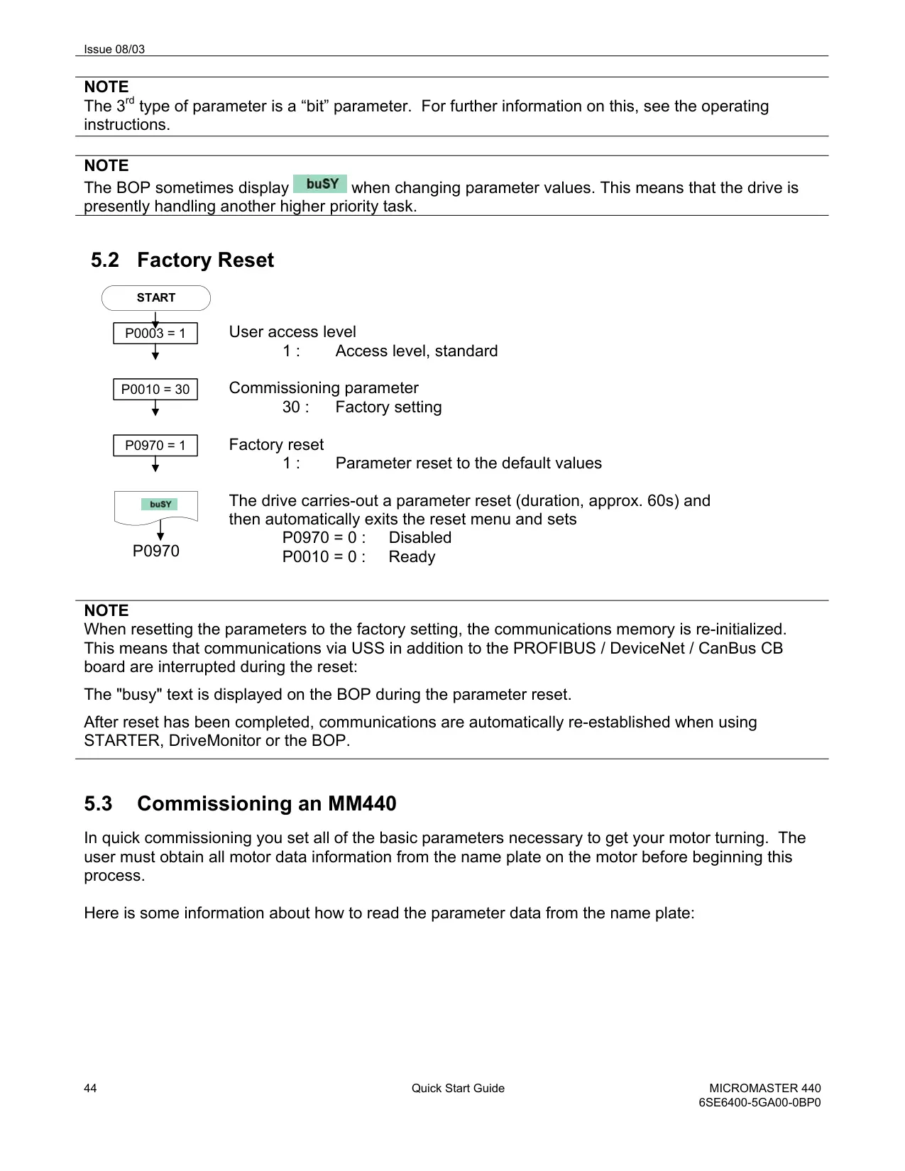
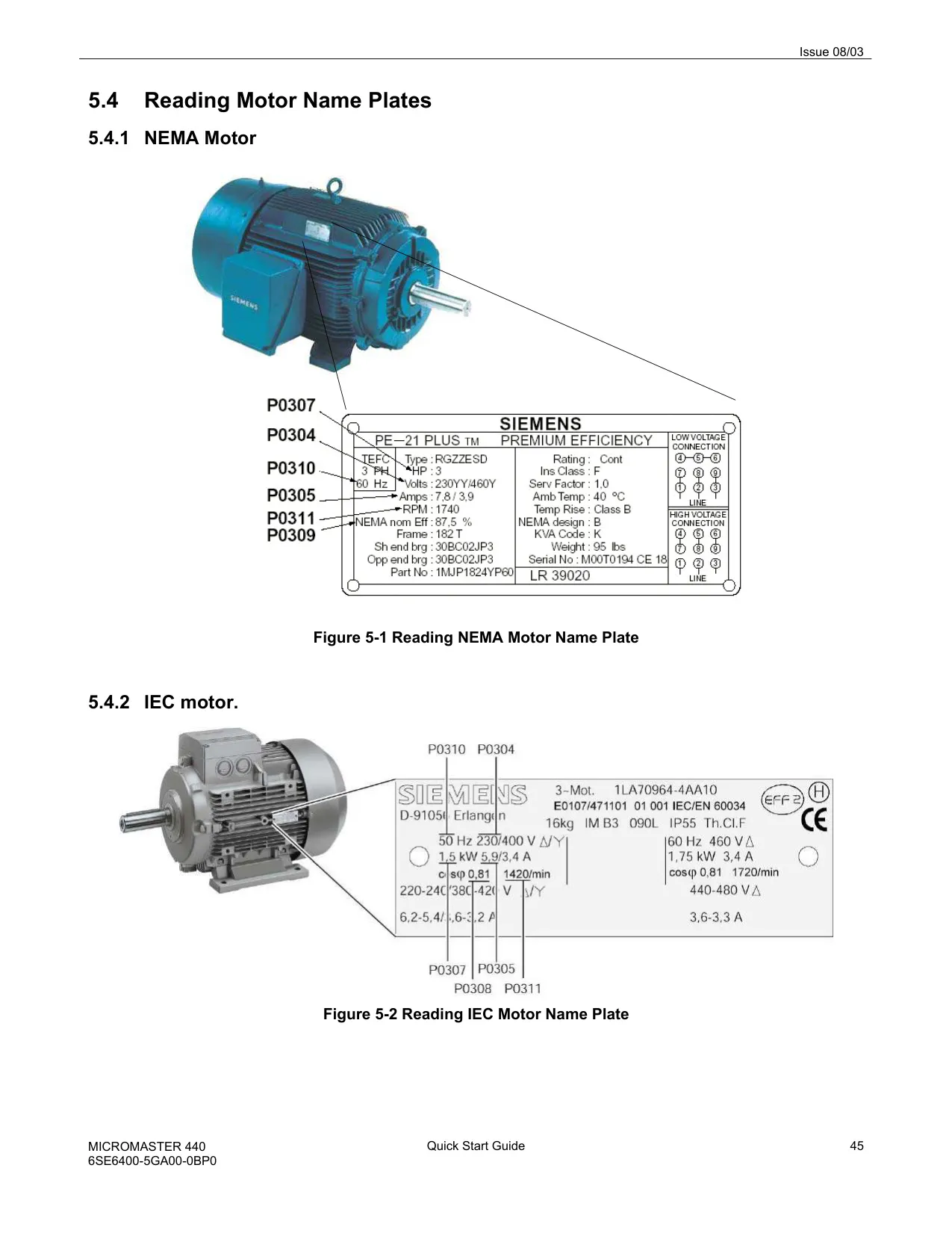

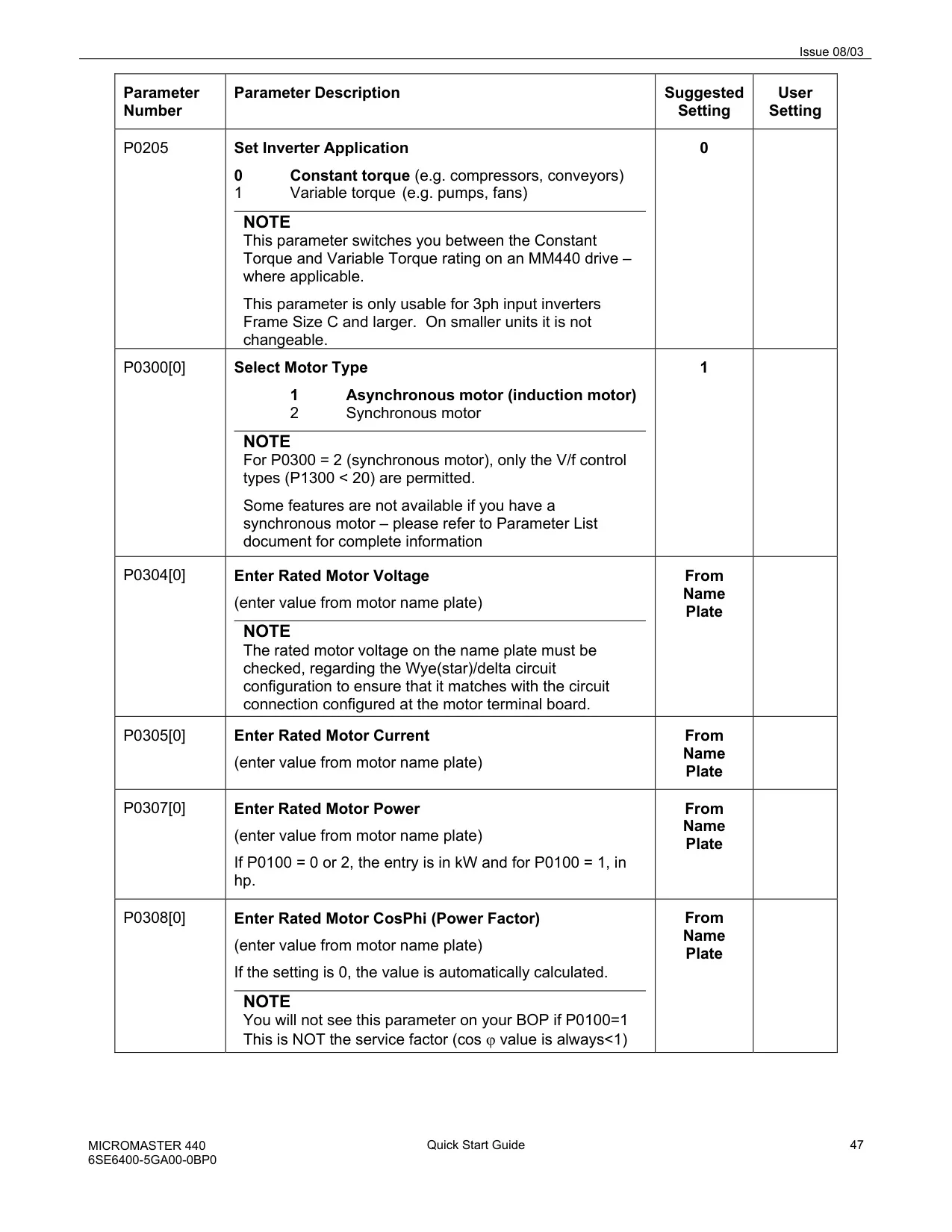

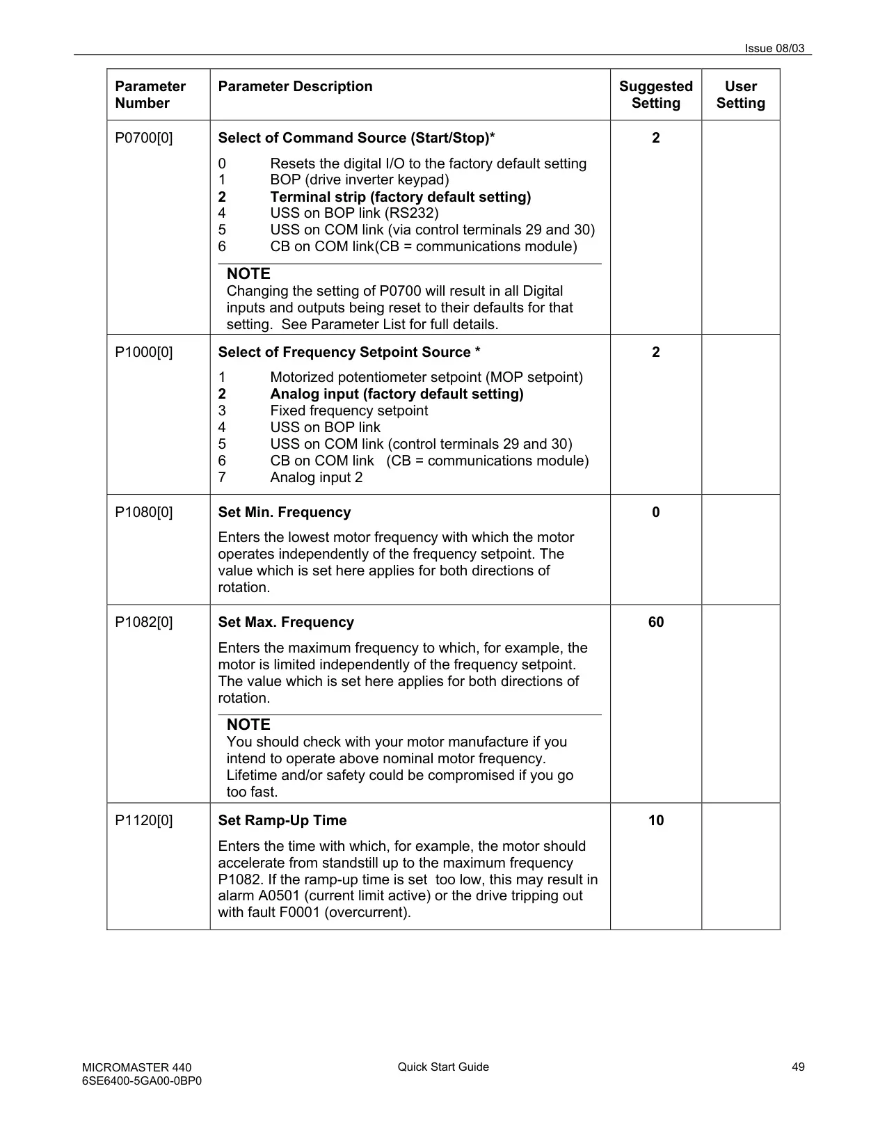

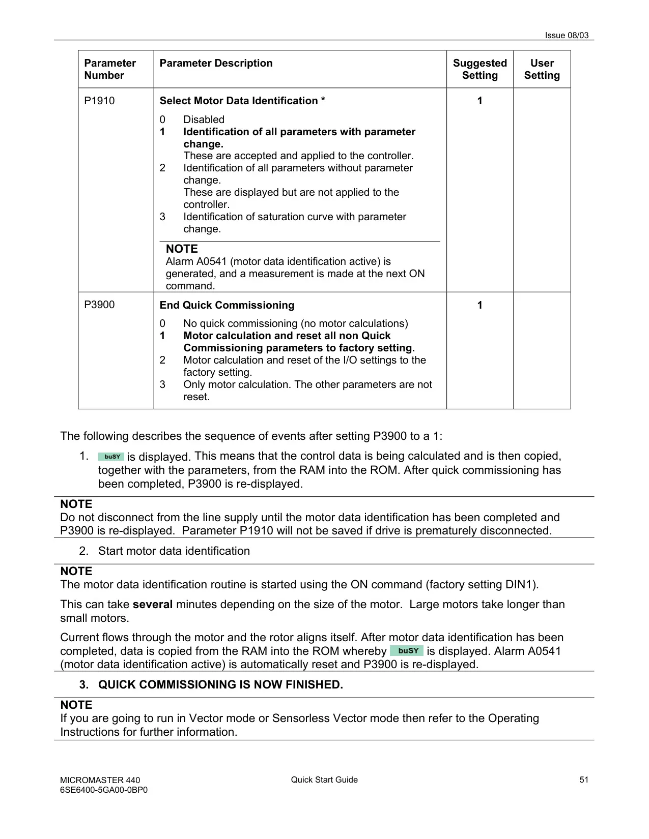

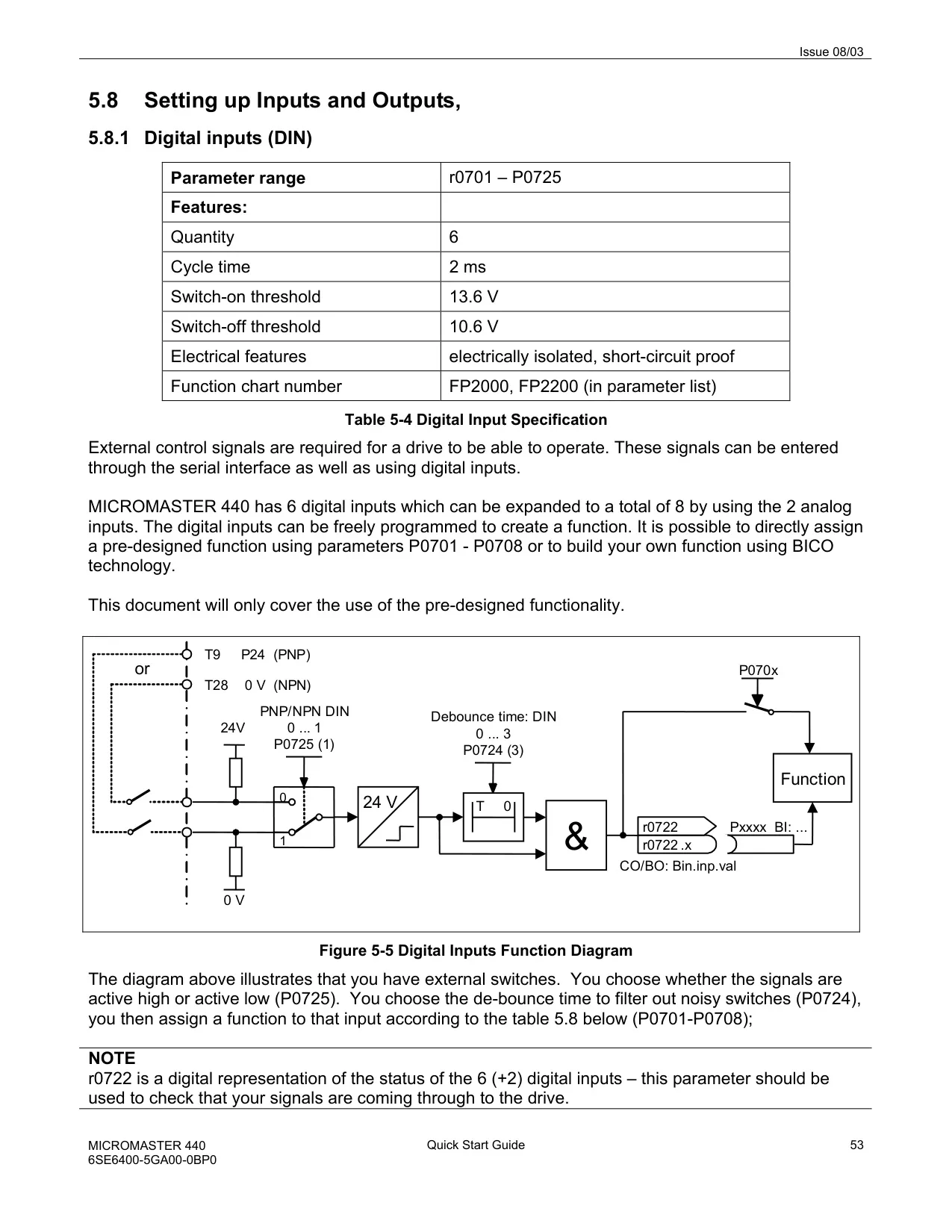

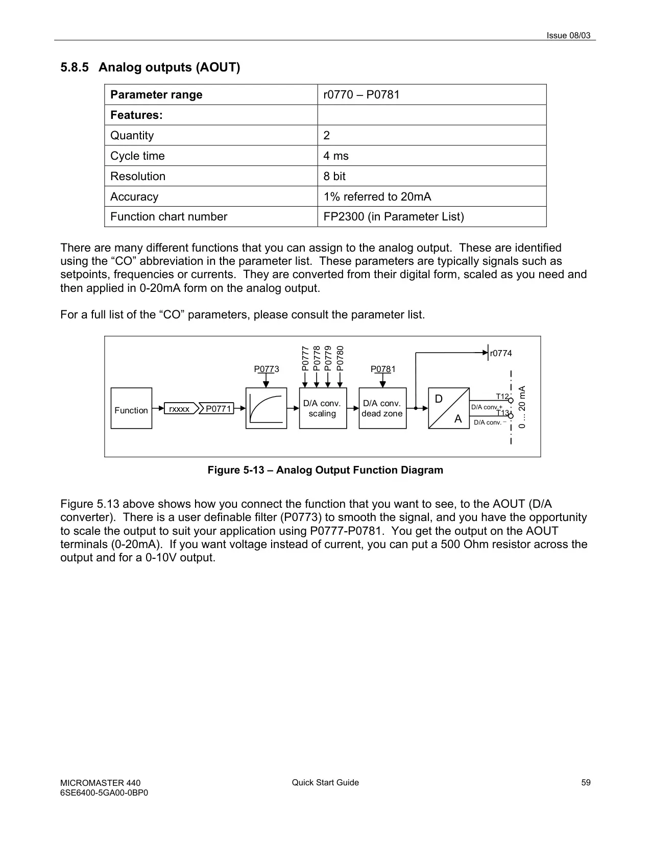
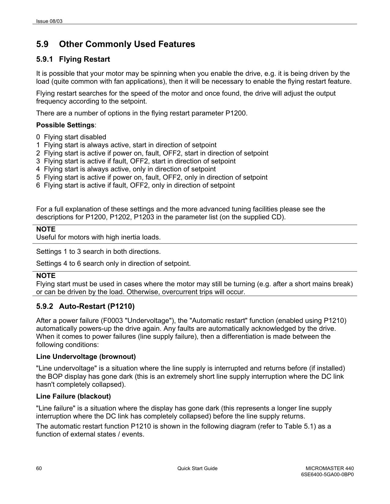



Siemens Micromaster 440 VFD Instructions
Here we offer the Siemens Micromaster 440 Variable Frequency Drive manual completely free and in English. We have cataloged this manual in the Variable Frequency Drives section on Manualverse, and it has been rated by 1 users with an average rating of 5. If you have any specific questions about Siemens Micromaster 440 Variable Frequency Drive, we suggest checking the Frequently Asked Questions (FAQs) section of this manual.
Product Images


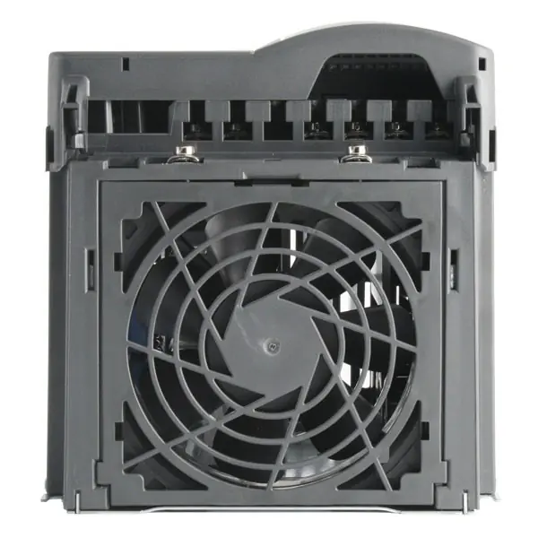


Siemens Micromaster 440 Variable Frequency Drive Specifications
| Feature | Specification |
|---|---|
| Mains Operating Voltage | 1 AC 200 to 240 V ±10% 3 AC 200 to 240 V ±10% 3 AC 380 to 480 V ±10% 3 AC 500 to 600 V ±10% |
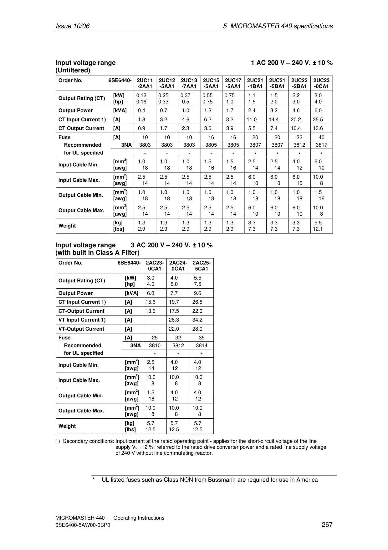
| Power Range (Constant Torque - CT) | 0.12 kW – 200 kW (0.16 hp – 268 hp) |
| Power Range (Variable Torque - VT) | 5.50 kW – 250 kW (7.50 hp – 335 hp) |
| Input Frequency | 47 to 63 Hz |
| Output Frequency | 0 Hz to 650 Hz |
| Power Factor | 0.95 |
| Inverter Efficiency | Frame Sizes A to F: 96% to 97% Frame Sizes FX and GX: 97% to 98% |
| Overload Capability (CT) | 150% for 60s (Frame A-F); 136% for 57s (Frame FX-GX) |
| Overload Capability (VT) | 110% for 60s (Frame A-F); 110% for 59s (Frame FX-GX) |
| Power-ON-OFF Cycle Time | Frame Sizes A to E: every 30 s Frame Size F: every 150 s Frame Sizes FX and GX: every 300 s |
| Control Methods | V/f control (Linear, FCC, Parabolic, Multi-point, independent voltage setpoint) Vector control (Sensorless Vector Control (SLVC), SLVC Torque Control, Speed control with Encoder Feedback, Torque control with Encoder Feedback) |
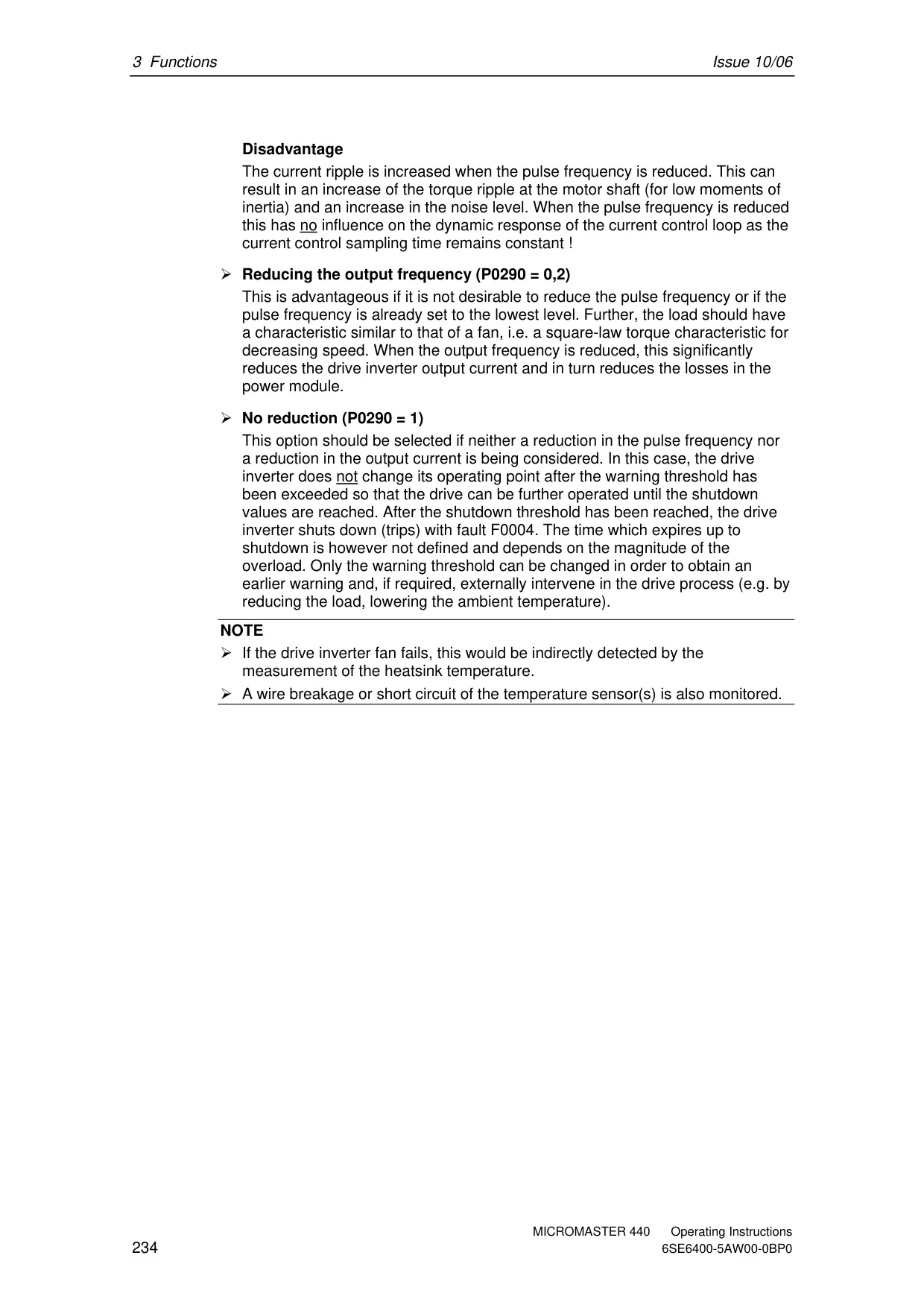
| Pulse Frequency | 2 kHz to 16 kHz (Frame A-F, standard 4 kHz) 2 kHz to 4 kHz (Frame FX-GX, standard 2 kHz (VT), 4 kHz (CT)) |
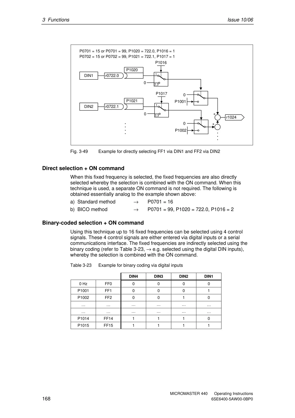
| Fixed Frequencies | 15, programmable |
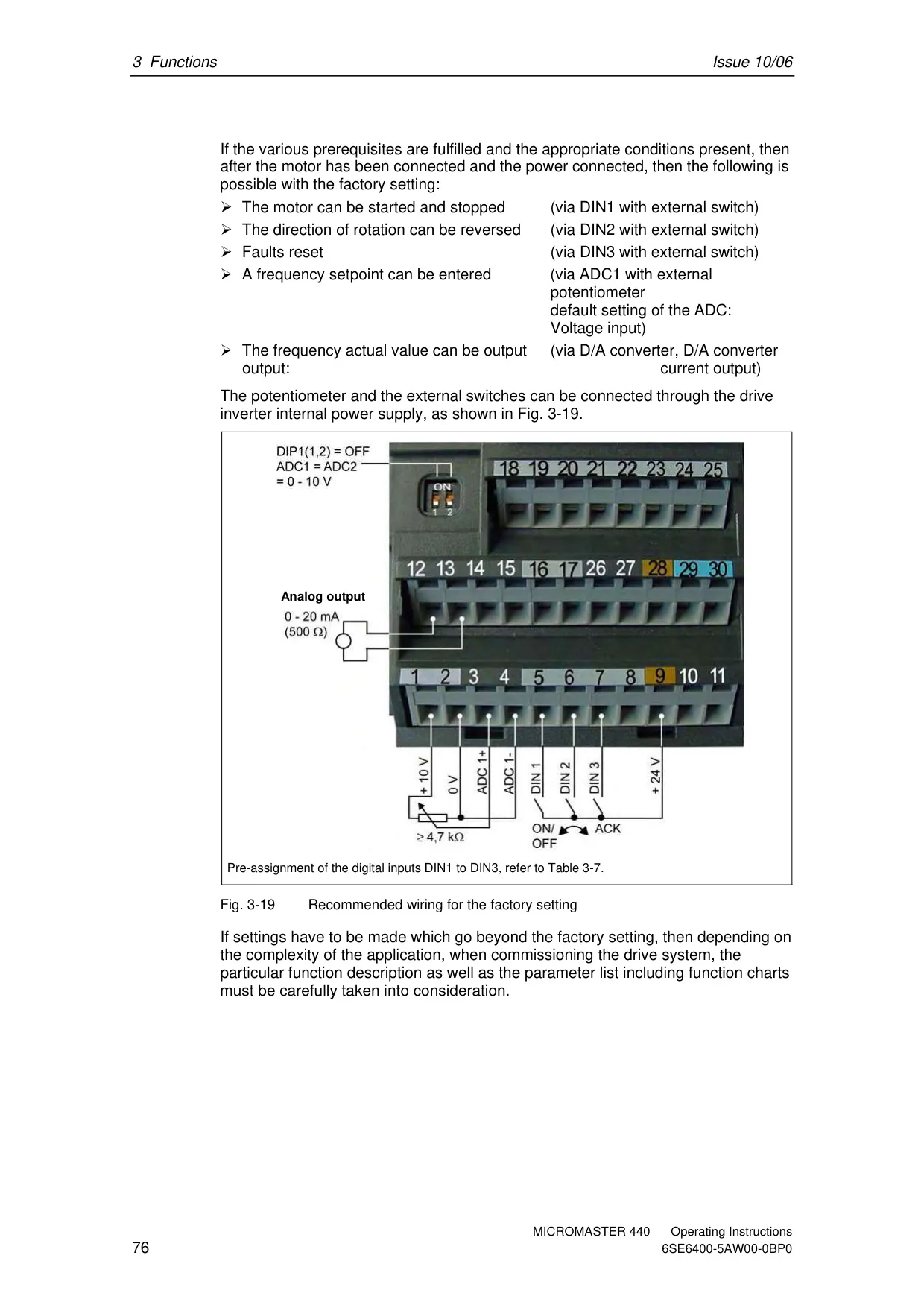
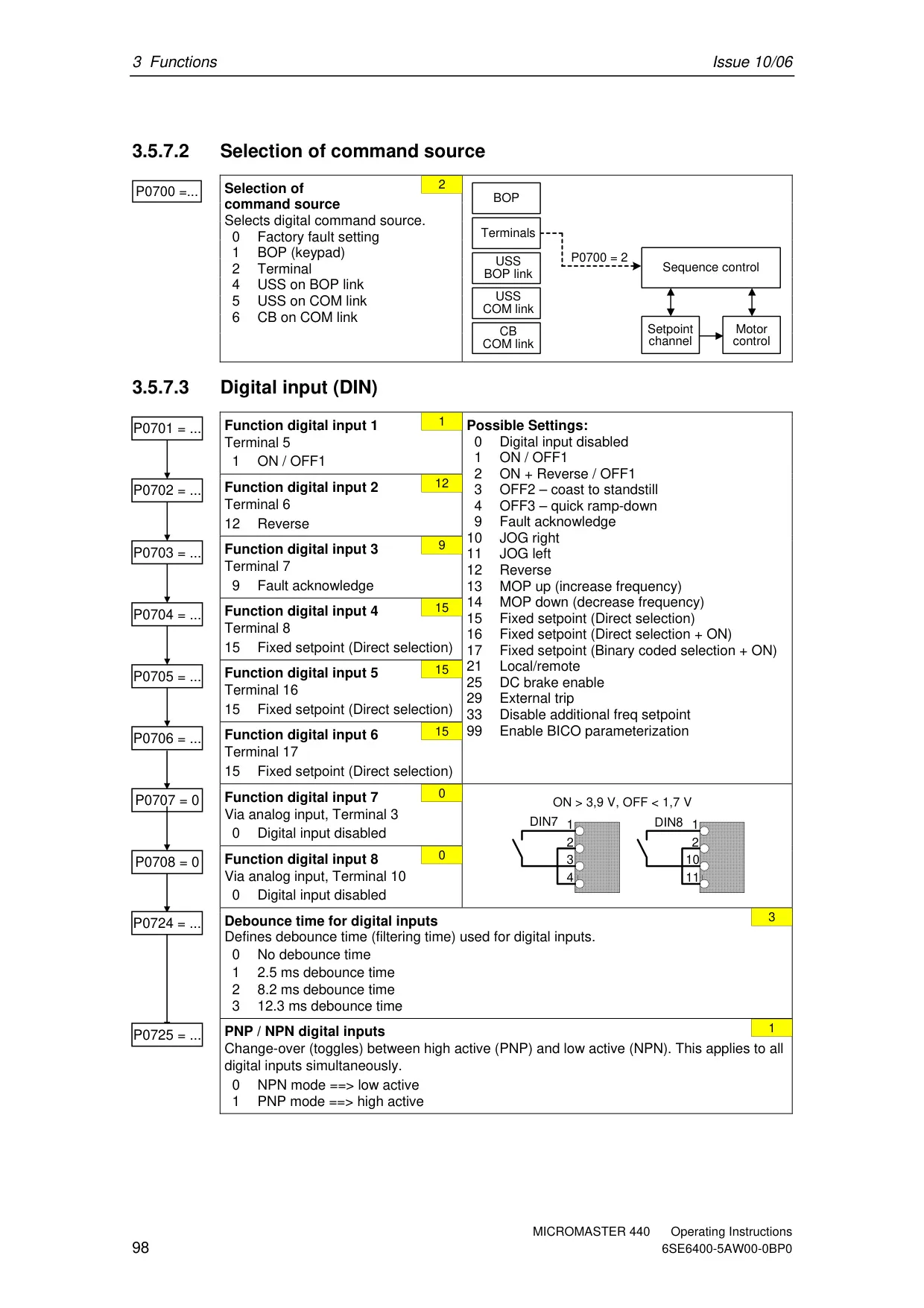
| Digital Inputs | 6 (expandable to 8), programmable, isolated, switchable PNP/NPN |
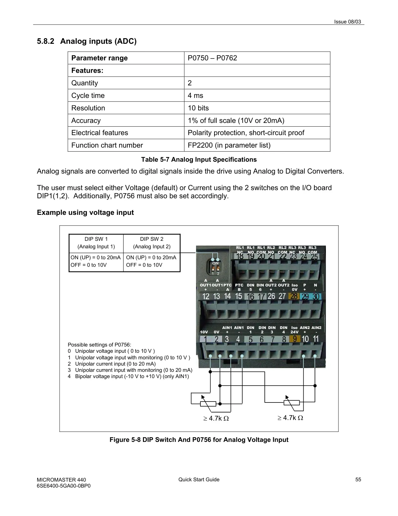
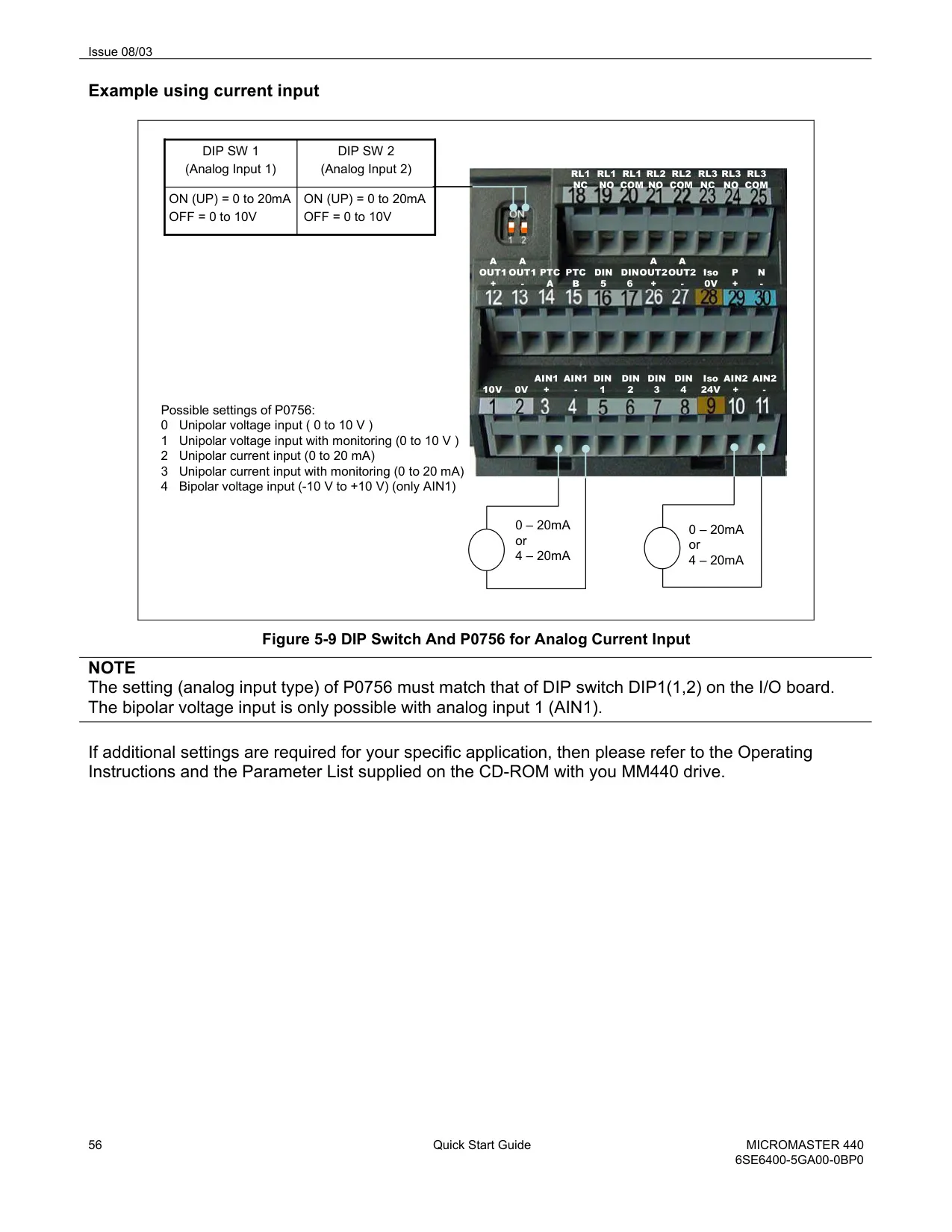
| Analog Inputs | 2 (ADC1: 0-10V, 0-20mA, -10 to +10V; ADC2: 0-10V, 0-20mA) |
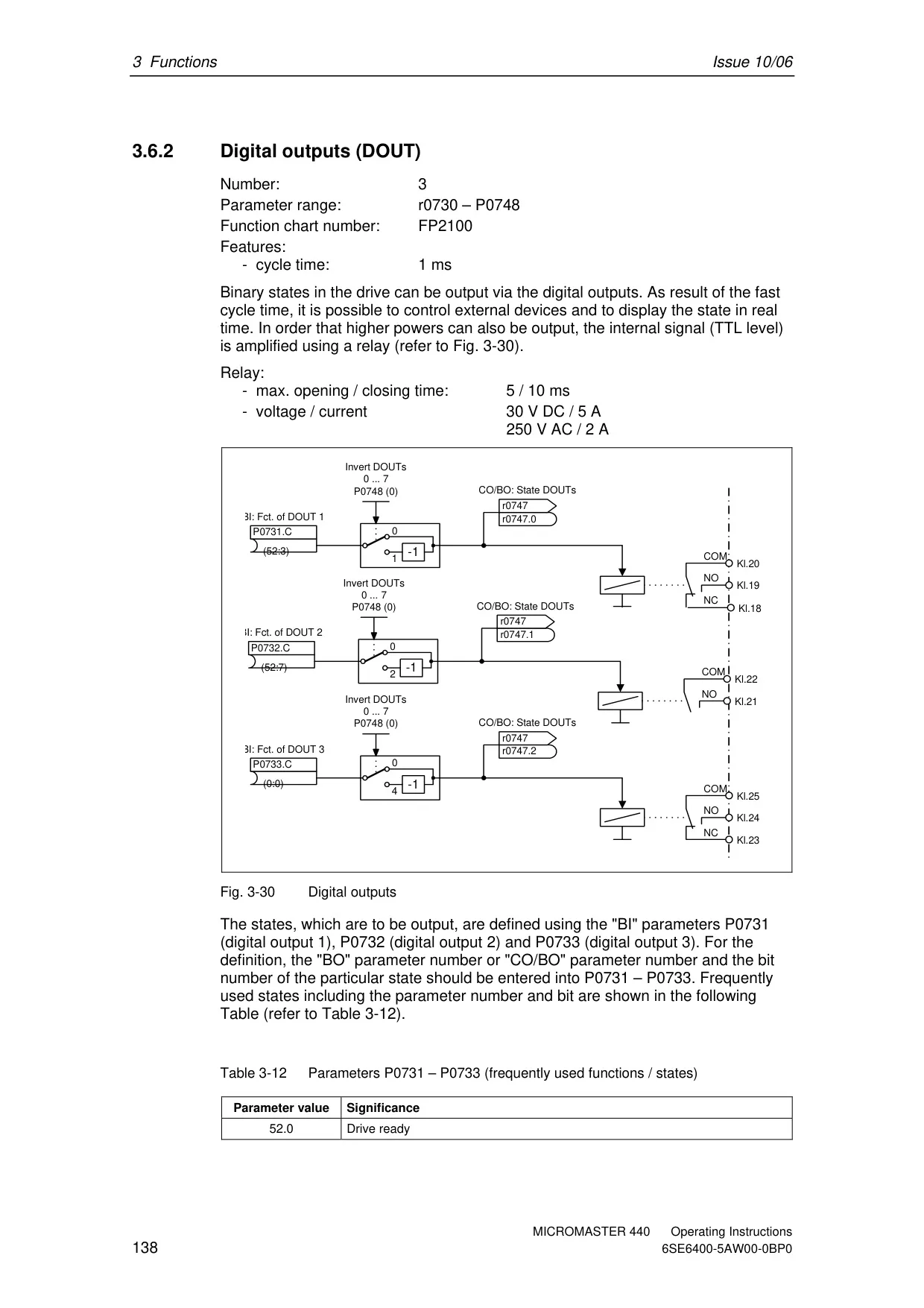
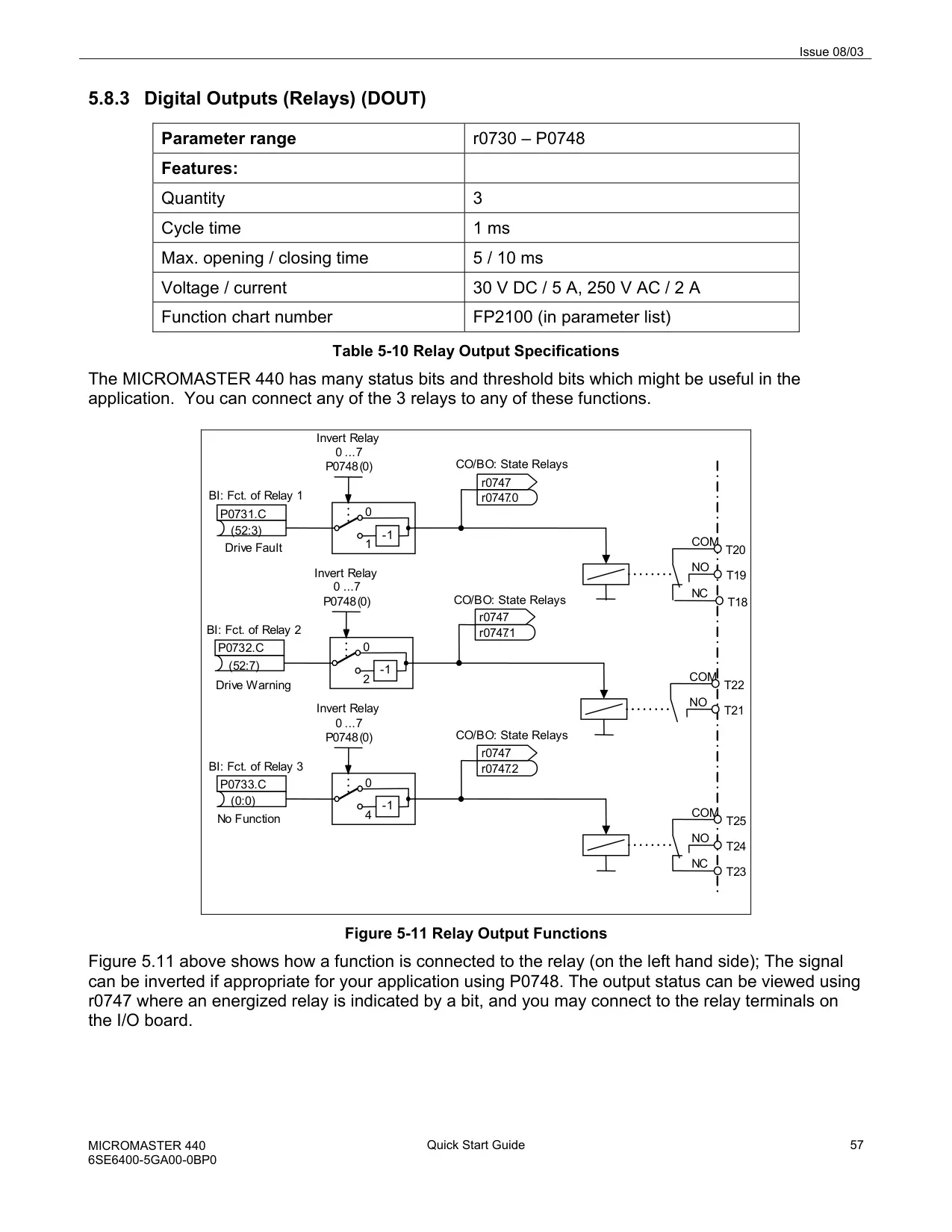
| Relay Outputs | 3, programmable (30V DC / 5A resistive, 250V AC / 2A inductive) |
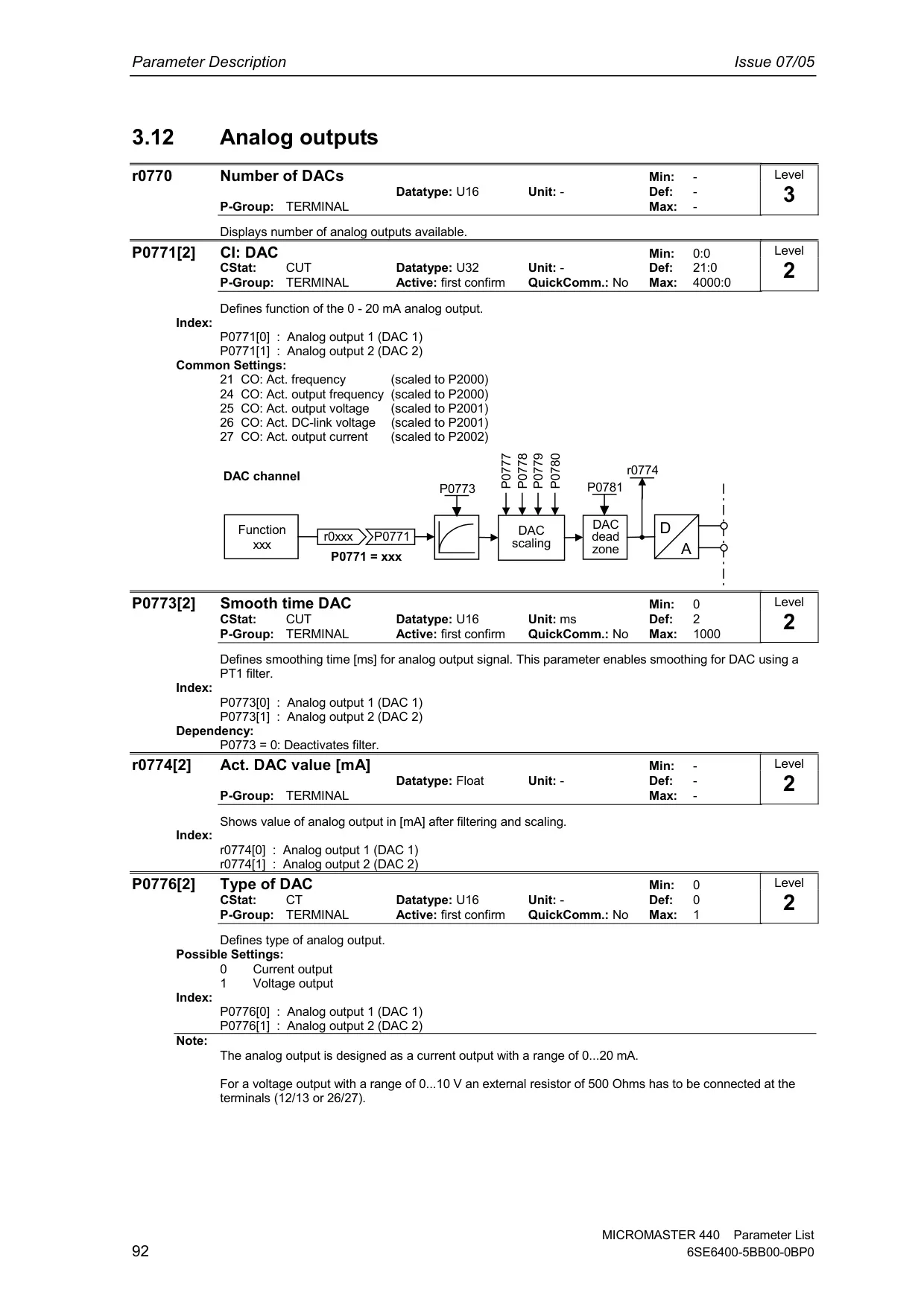
| Analog Outputs | 2, programmable (0 to 20mA) |
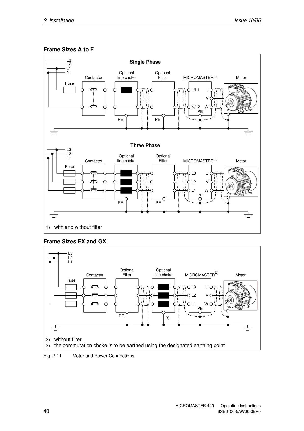
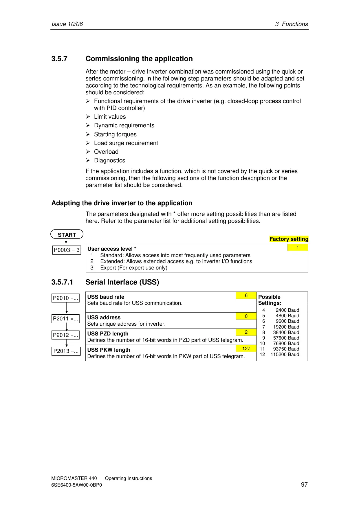
| Serial Interface | Internal RS485 interface (port), optional RS232 |
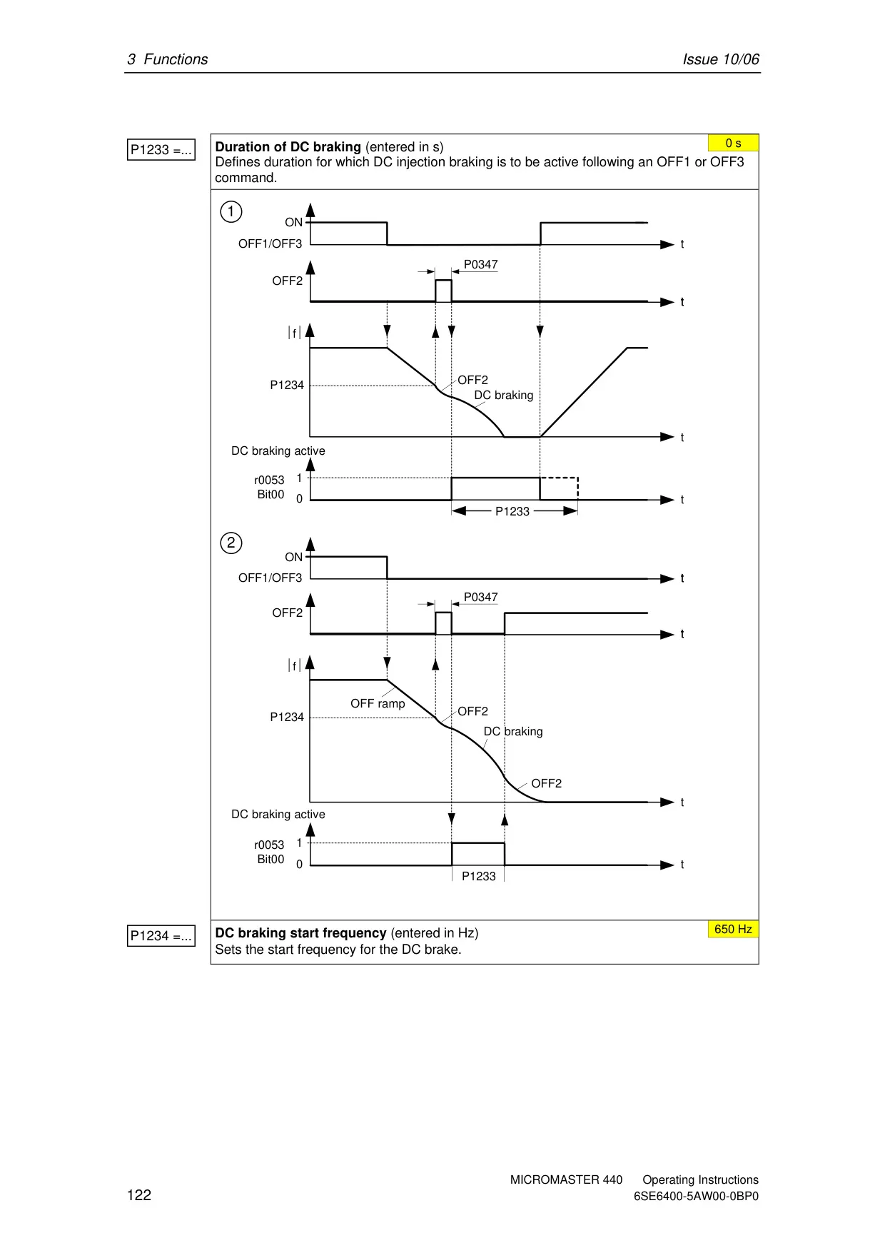
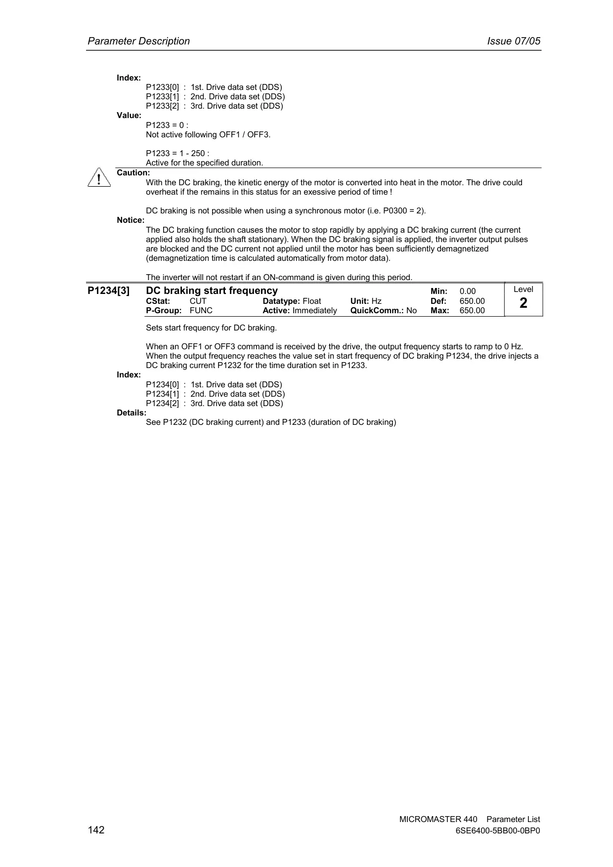
| Braking | DC braking, Compound braking, Dynamic braking (integrated chopper for Frame A-F, external for FX-GX) |
| Protection Level | IP20 |
| Operating Temperature | -10°C to +50°C (CT, Frame A-F); -10°C to +40°C (VT, Frame A-F) 0°C to +40°C (Frame FX-GX, up to 55°C with derating) |
| Storage Temperature | -40°C to +70°C |
| Humidity | < 95% RH – non-condensing |
| Altitude | Up to 1000 m without derating (A-F); Up to 2000 m without derating (FX-GX) |
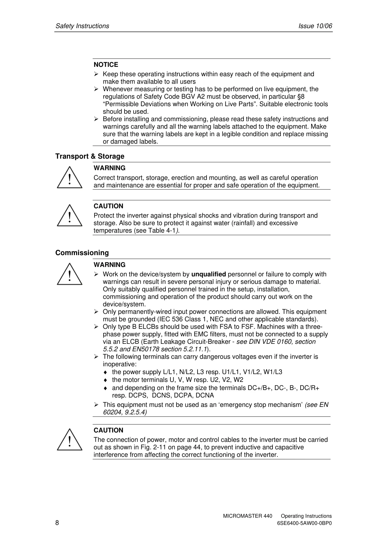
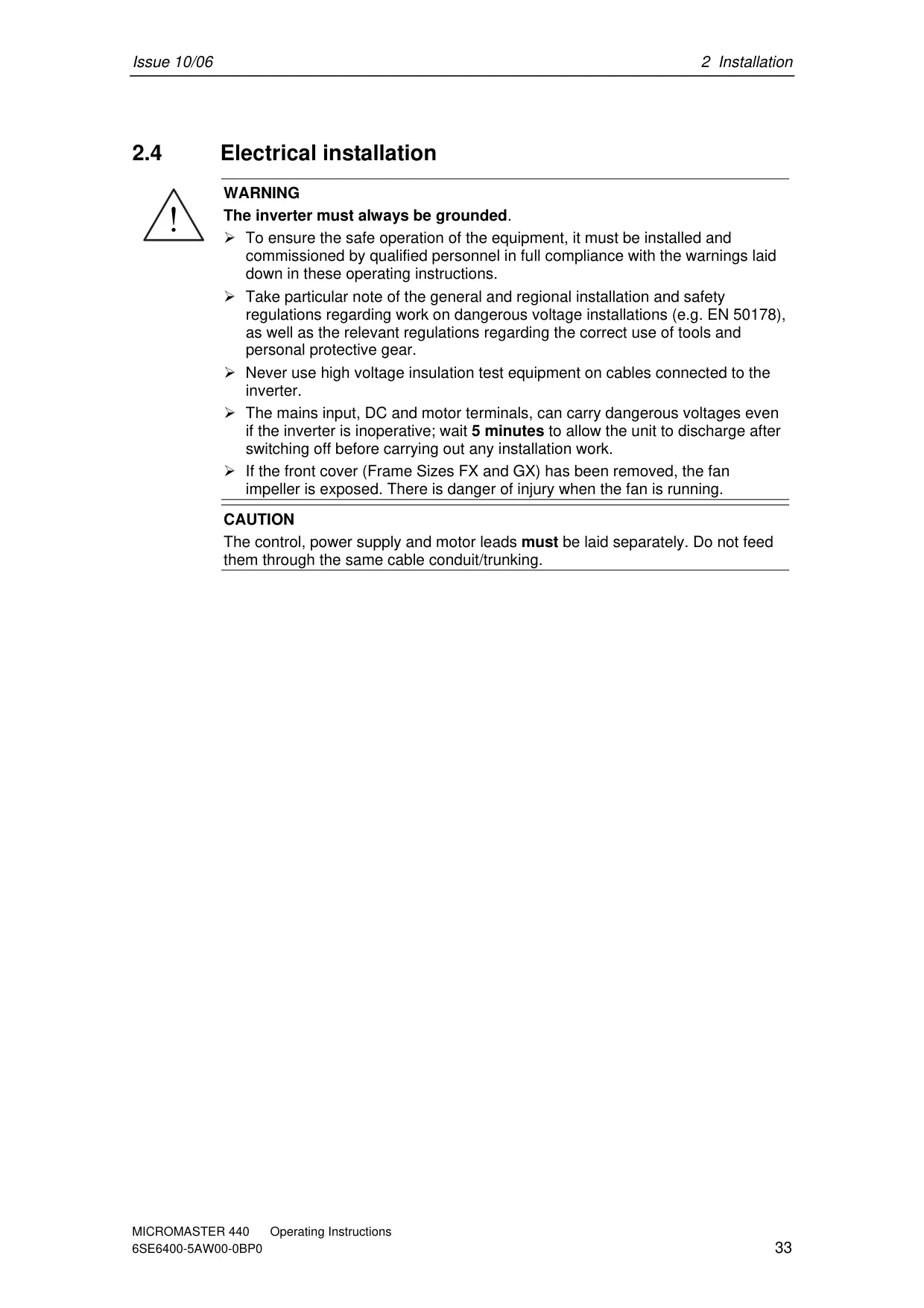
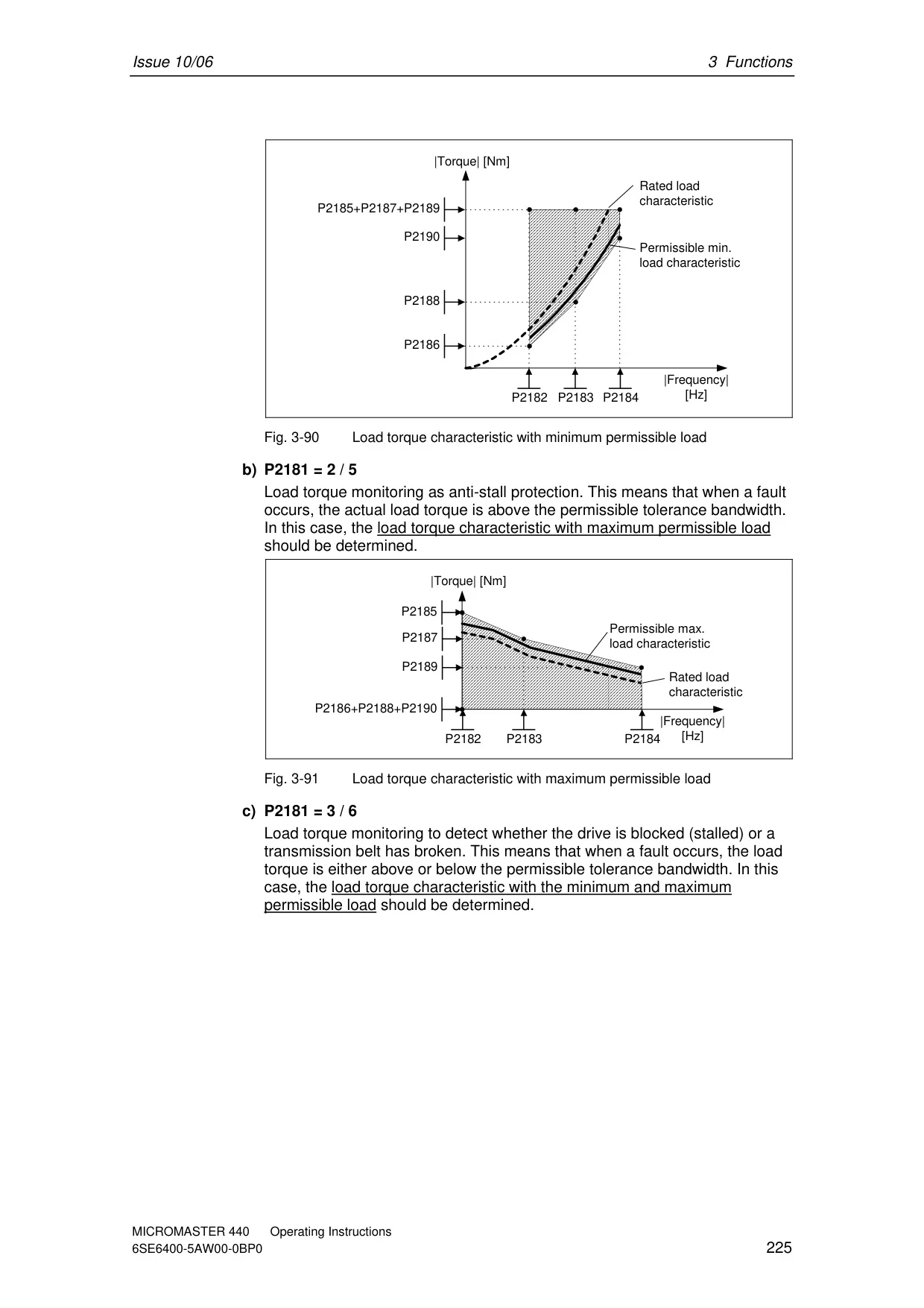
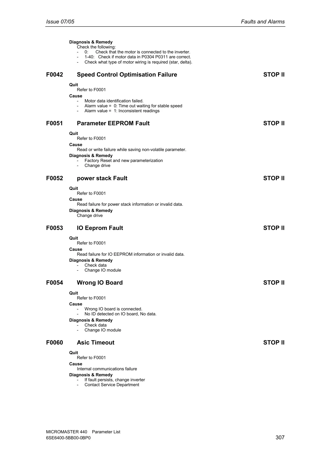
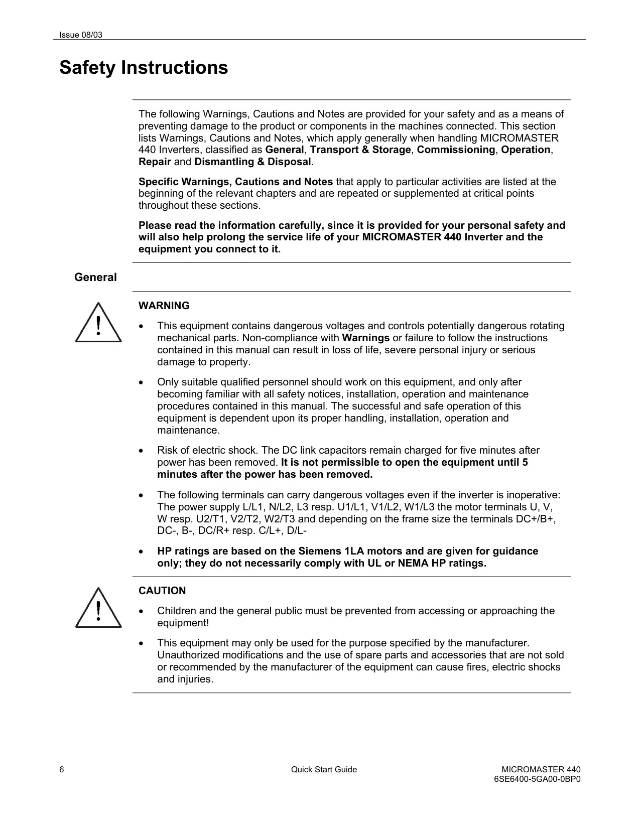
| Protection Features | Undervoltage, Overvoltage, Overload, Ground Faults, Short circuit, Stall Prevention, Motor Blocking Protection, Motor Overtemperature, Inverter Overtemperature, Parameter Interlock |
| Standards | UL, cUL, CE, C-tick |
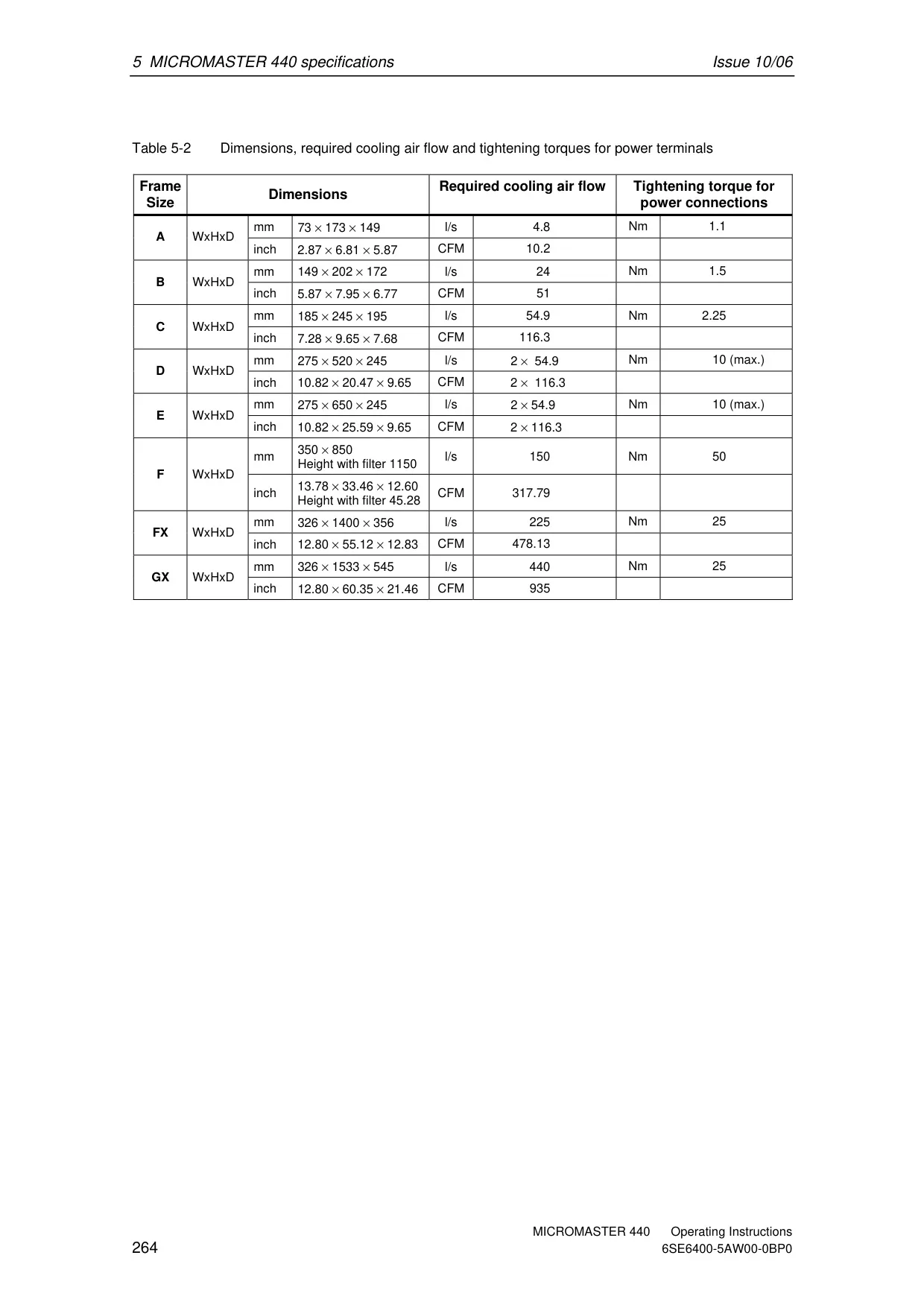
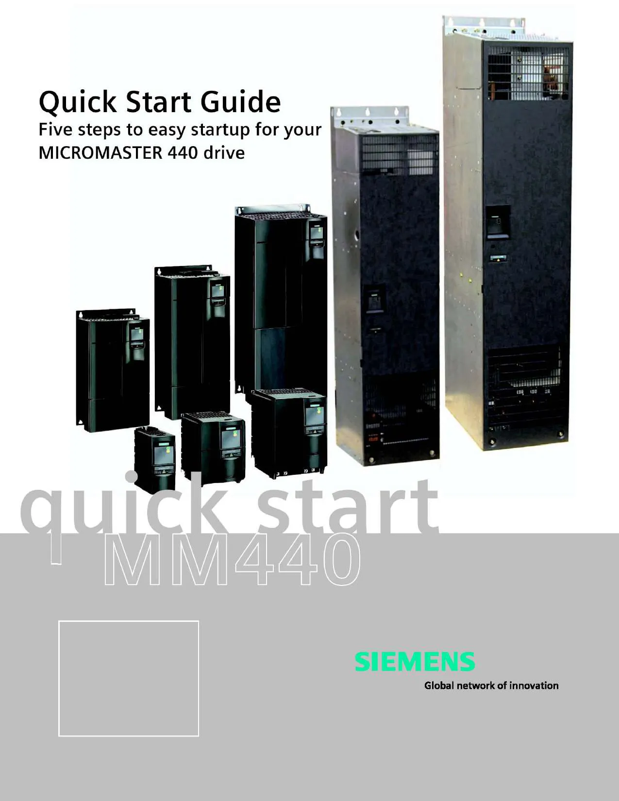
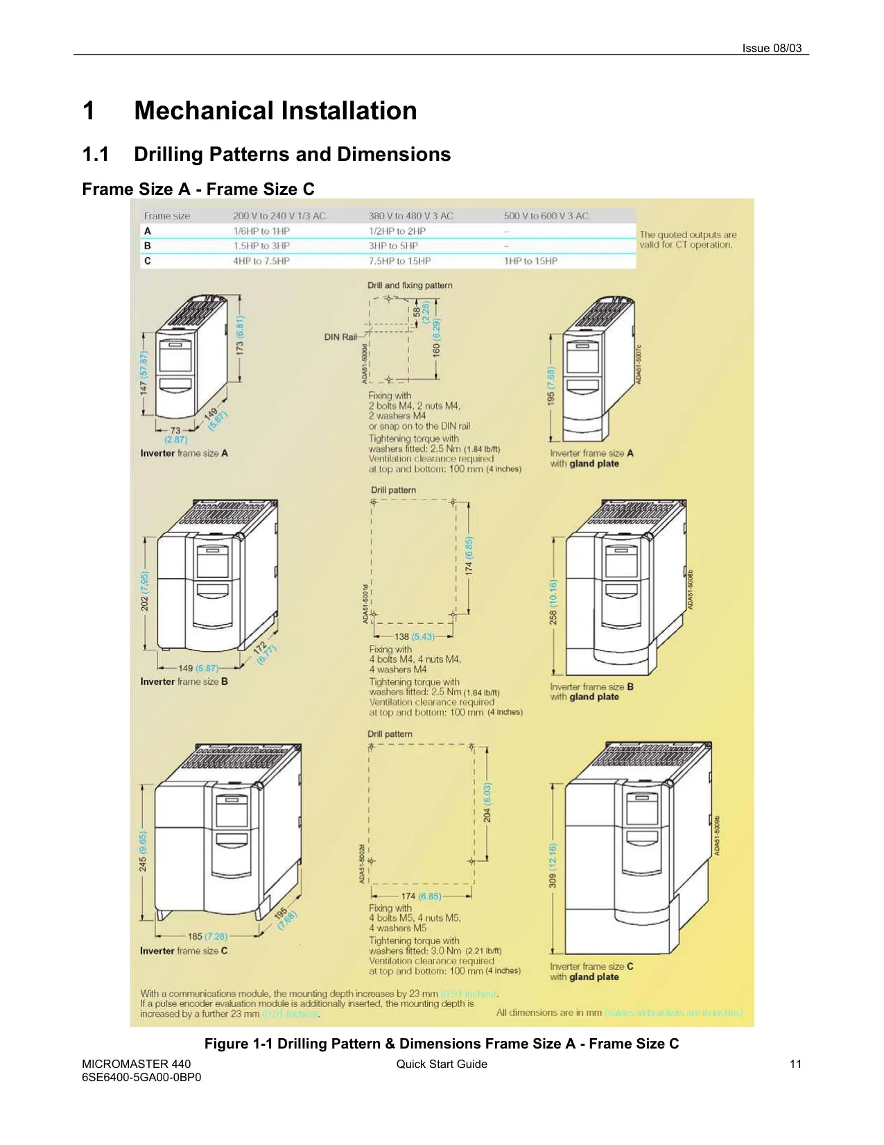
| Dimensions (W x H x D) | Frame A: 73x173x149 mm Frame B: 149x202x172 mm Frame C: 185x245x195 mm Frame D: 275x520x245 mm Frame E: 275x650x245 mm Frame F: 350x850x320 mm (Height with filter 1150 mm) Frame FX: 326x1400x356 mm Frame GX: 326x1533x545 mm |
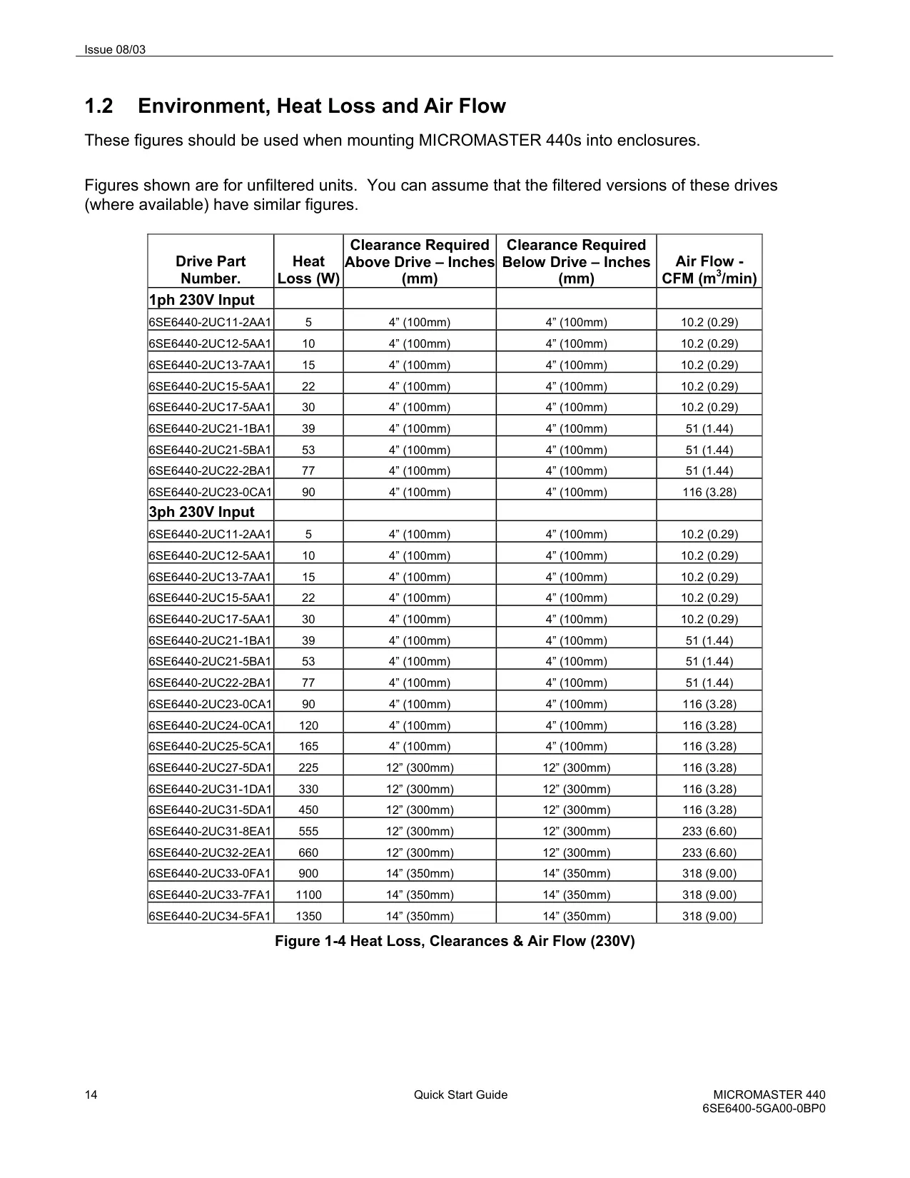
| Required Cooling Air Flow | Frame A: 4.8 l/s Frame B: 24 l/s Frame C: 54.9 l/s Frame D/E: 2 x 54.9 l/s Frame F: 150 l/s Frame FX: 225 l/s Frame GX: 440 l/s |
| Tightening Torque (Power Terminals) | Frame A: 1.1 Nm Frame B: 1.5 Nm Frame C: 2.25 Nm Frame D/E: 10 Nm (max.) Frame F: 50 Nm Frame FX/GX: 25 Nm |
Siemens Micromaster 440 VFD Details
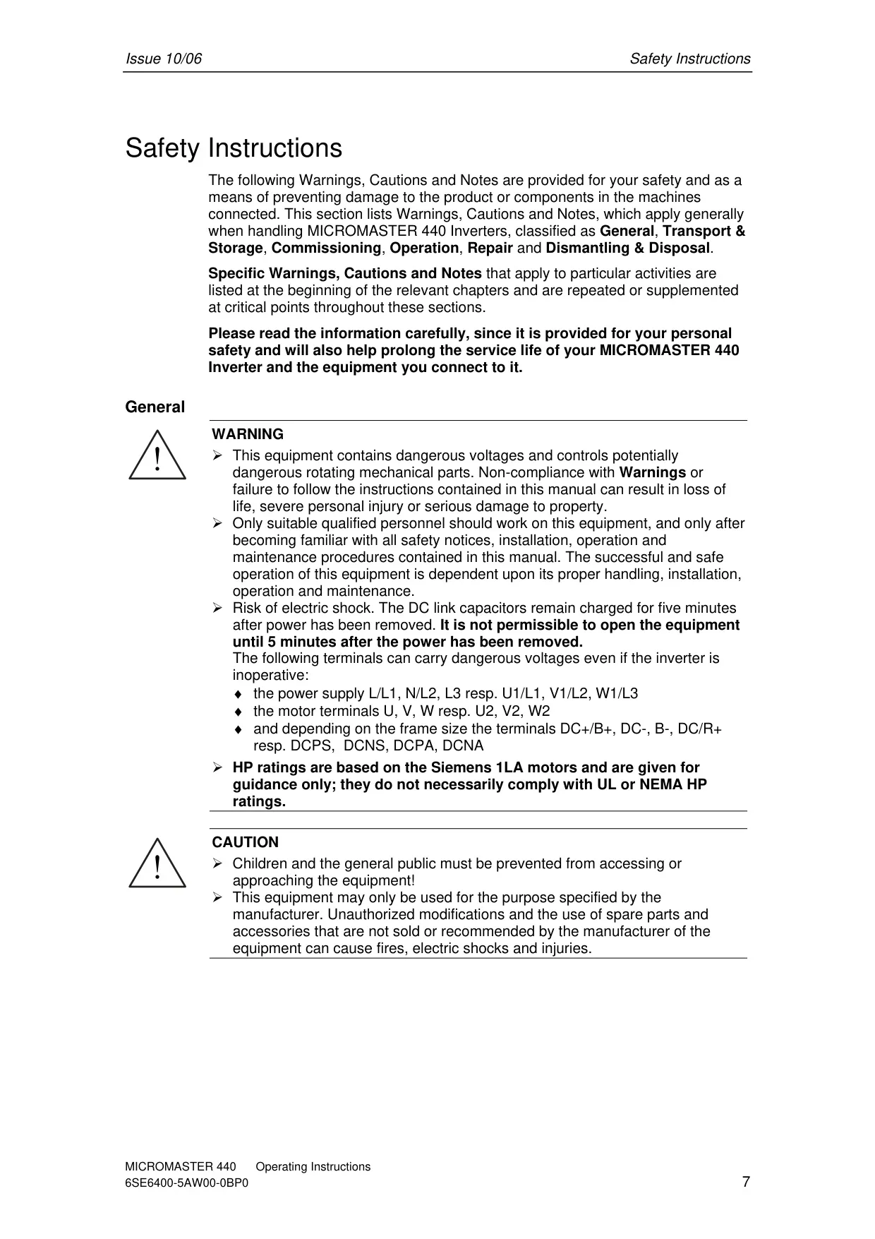
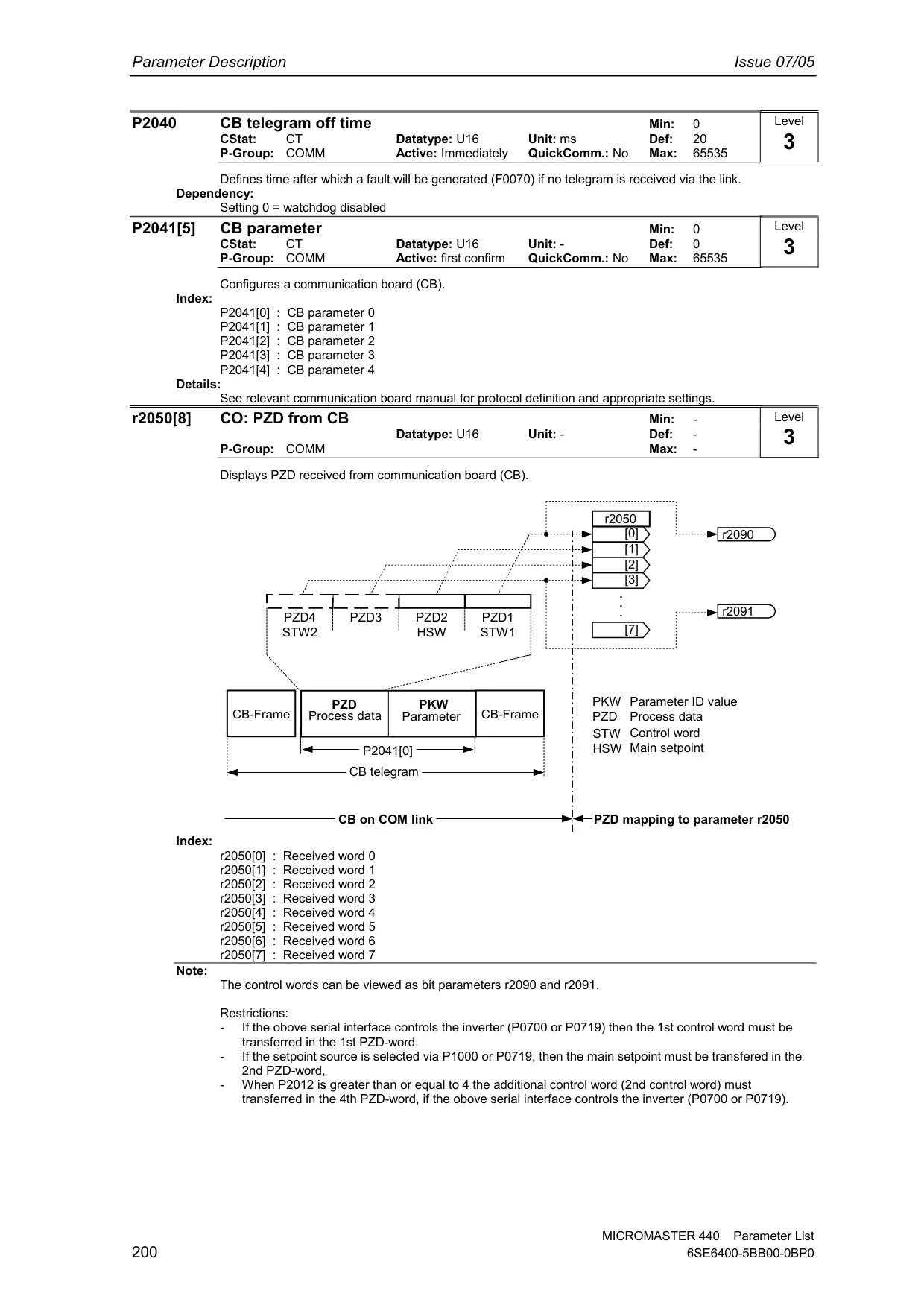
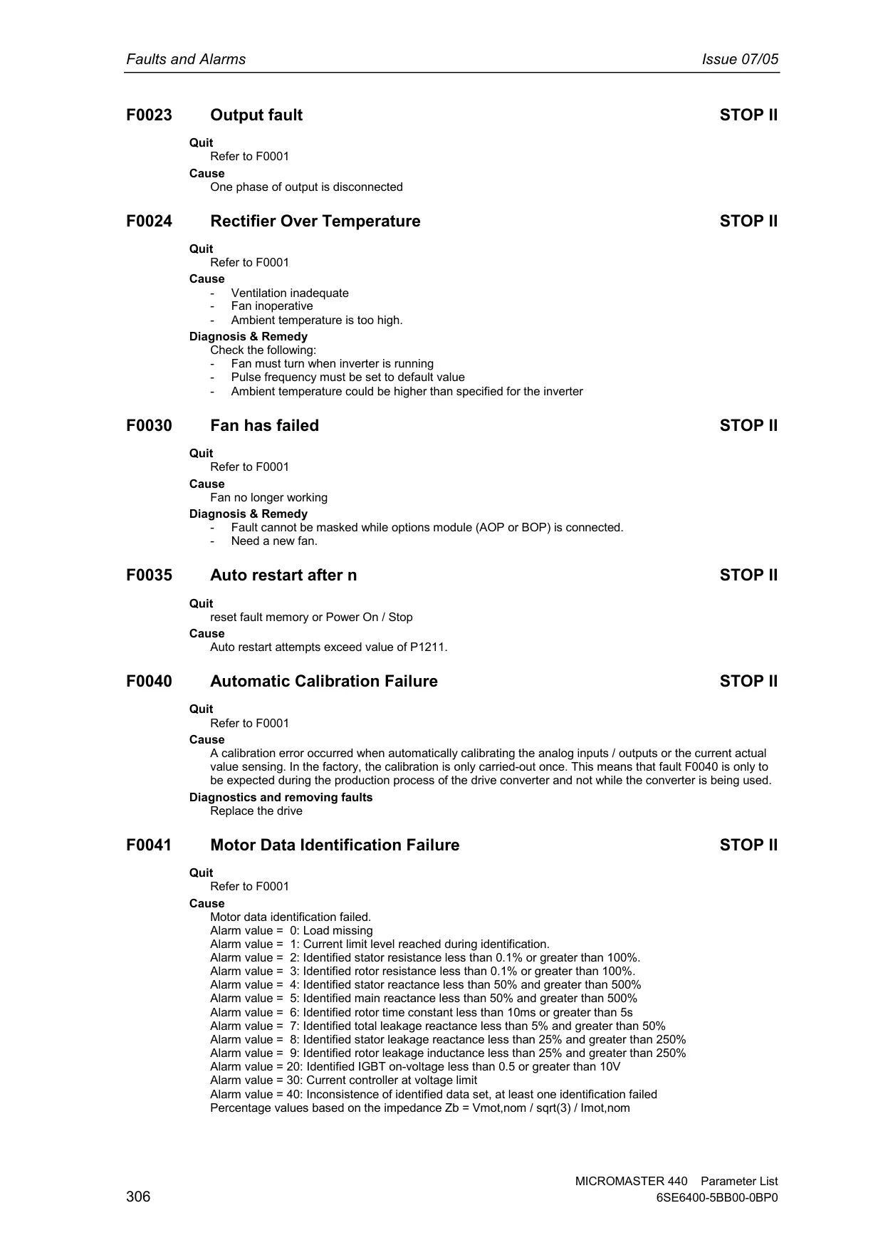
The Siemens Micromaster 440 Variable Frequency Drive (VFD) is a highly versatile and robust solution for controlling three-phase motors, leveraging advanced microprocessor control and Insulated Gate Bipolar Transistor (IGBT) technology for reliable and efficient operation. Its modular design ensures extremely flexible configuration, allowing it to be adapted to a wide array of applications, from standalone systems to complex automation architectures. The VFD's ability to operate with selectable pulse frequencies up to 16 kHz ensures exceptionally quiet motor operation, a significant advantage in noise-sensitive environments.
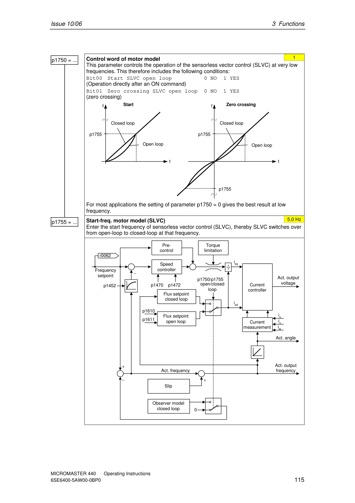
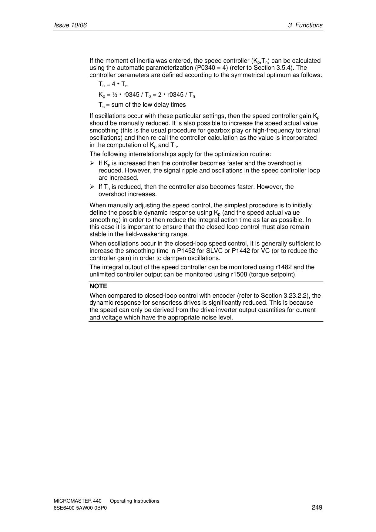
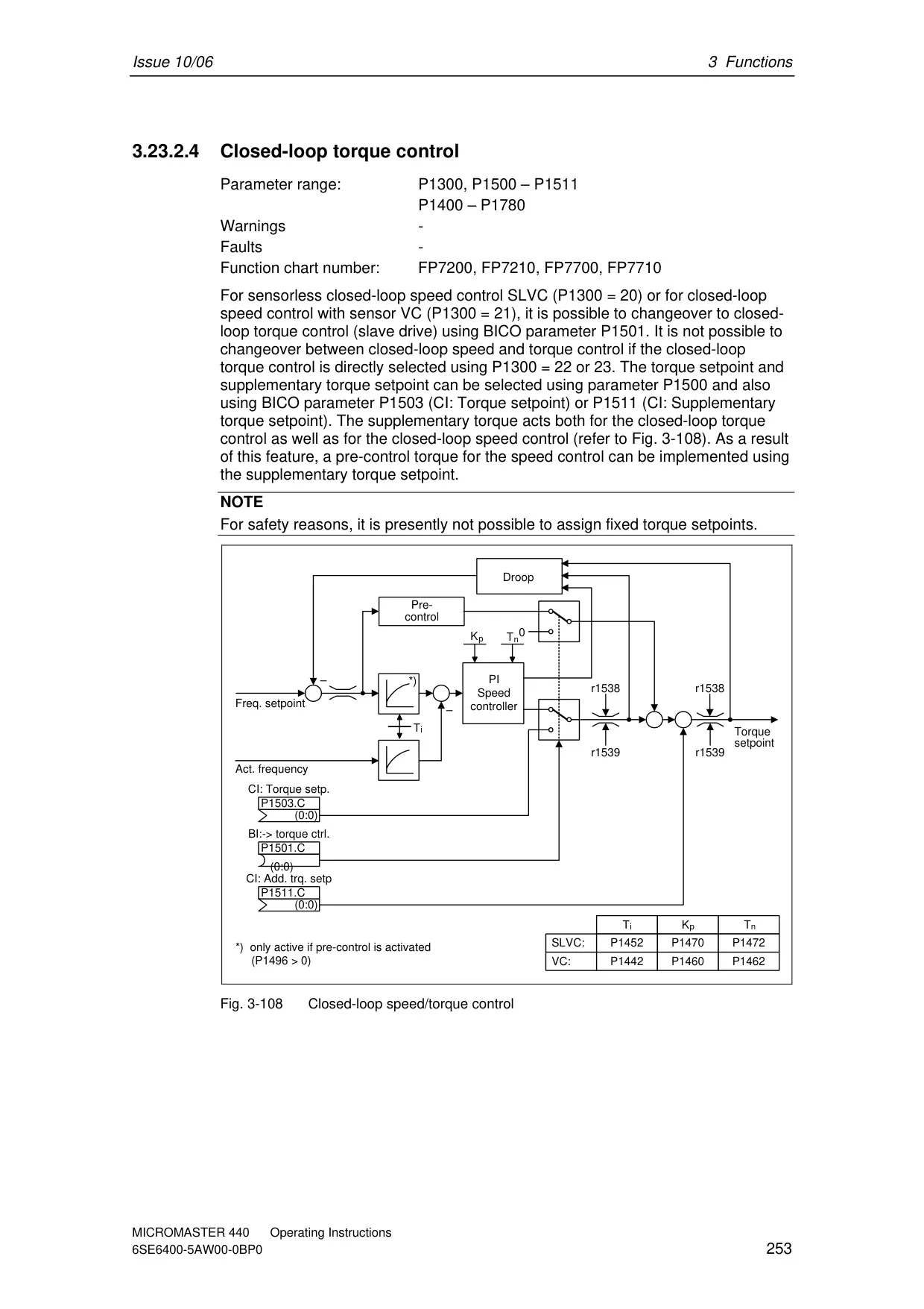
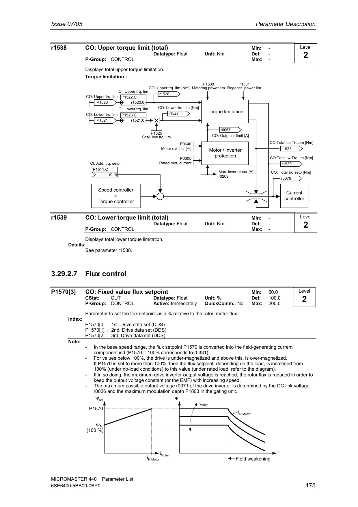
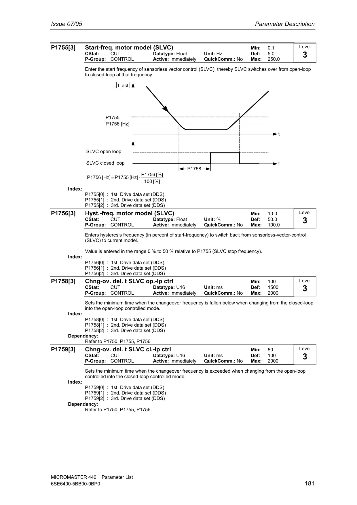
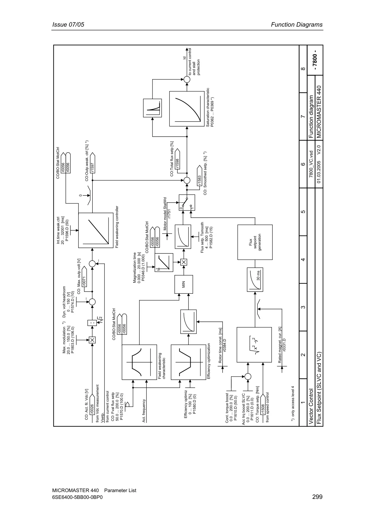
Beyond its core specifications, the Micromaster 440 offers a rich set of features designed to enhance control, protection, and diagnostic capabilities. For precise motor control, it supports Sensorless Vector Control (SLVC), ideal for applications requiring high torque performance and fast response to shock loading, even allowing torque holding at 0 Hz. For even higher accuracy, Vector Control with encoder (VC) provides stable and precise speed and torque regulation across the entire speed range.
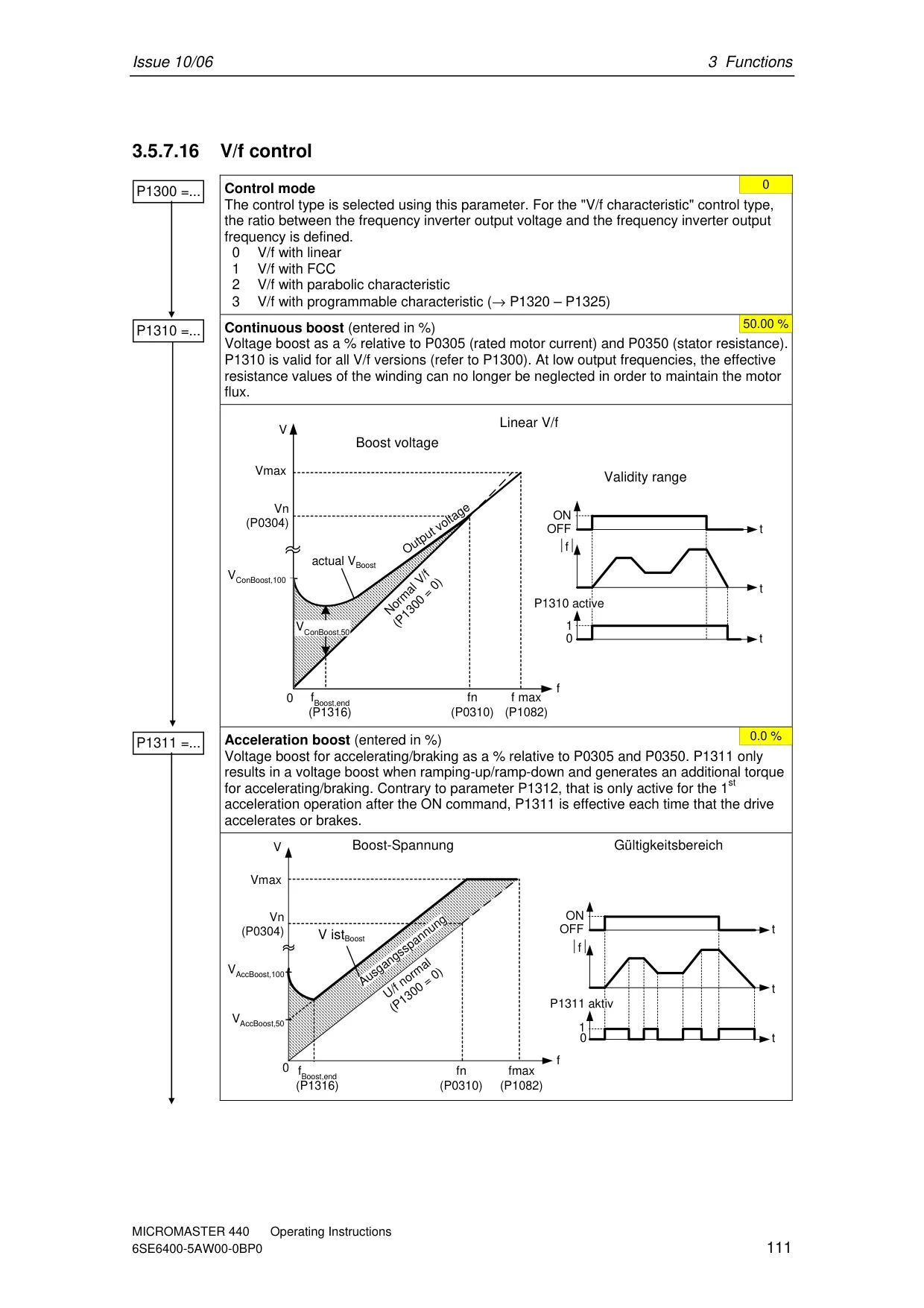
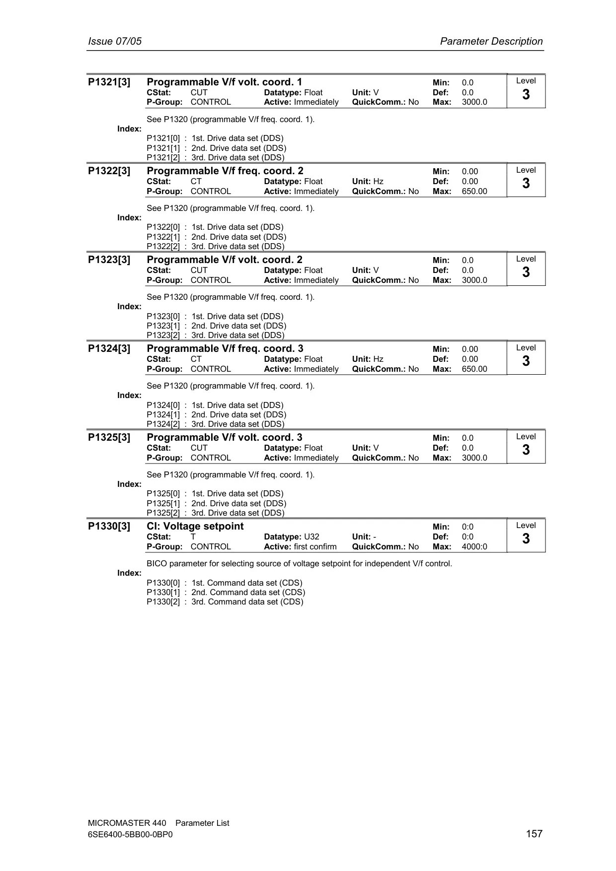
The drive incorporates sophisticated V/f Control methods, including Flux Current Control (FCC) for improved dynamic response and motor control, and multi-point V/f characteristics for tailored application needs. Key operational enhancements include Automatic Restart functionality, which enables the drive to automatically power up after a power failure, and Flying Restart, allowing seamless connection to a motor that is already spinning, preventing costly downtime.
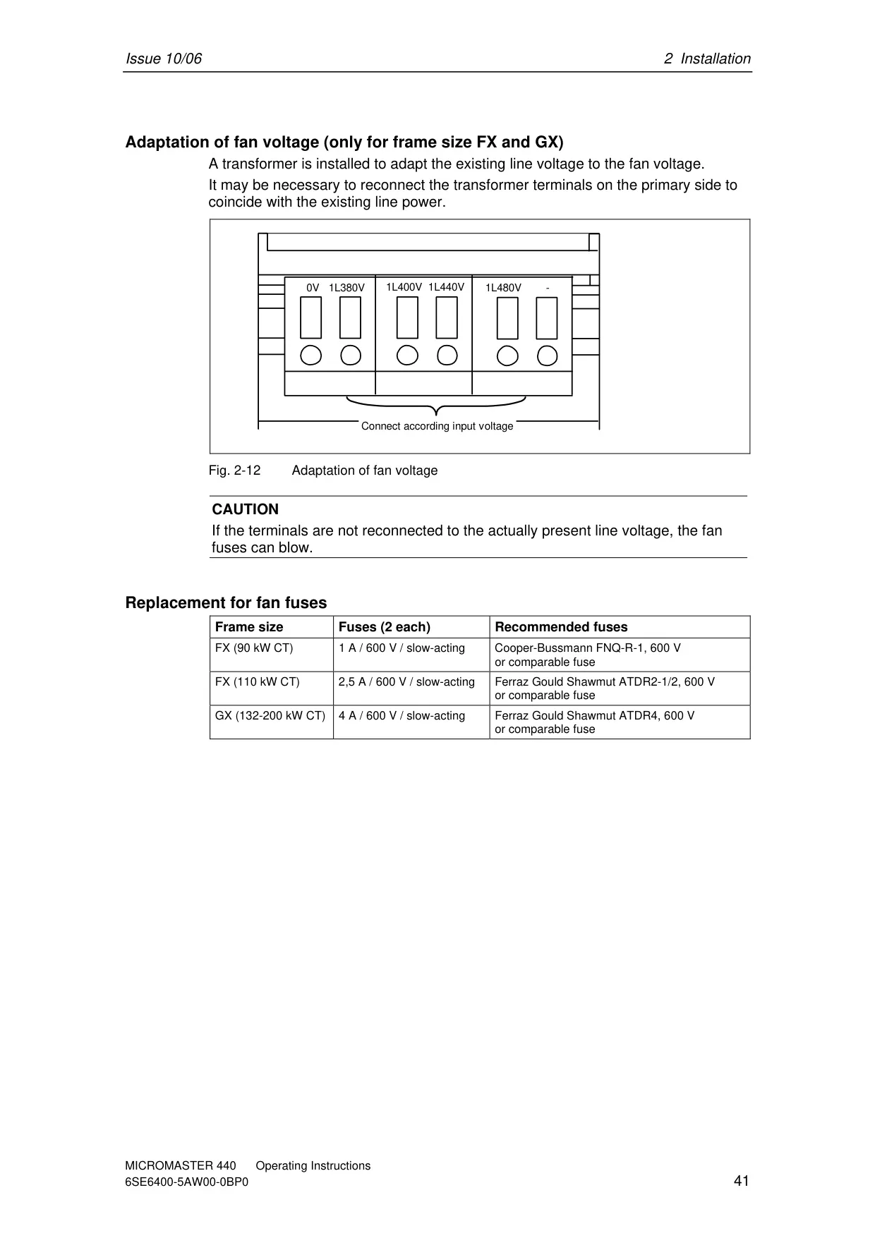
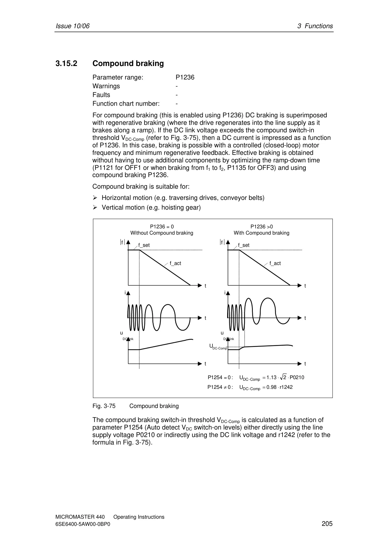
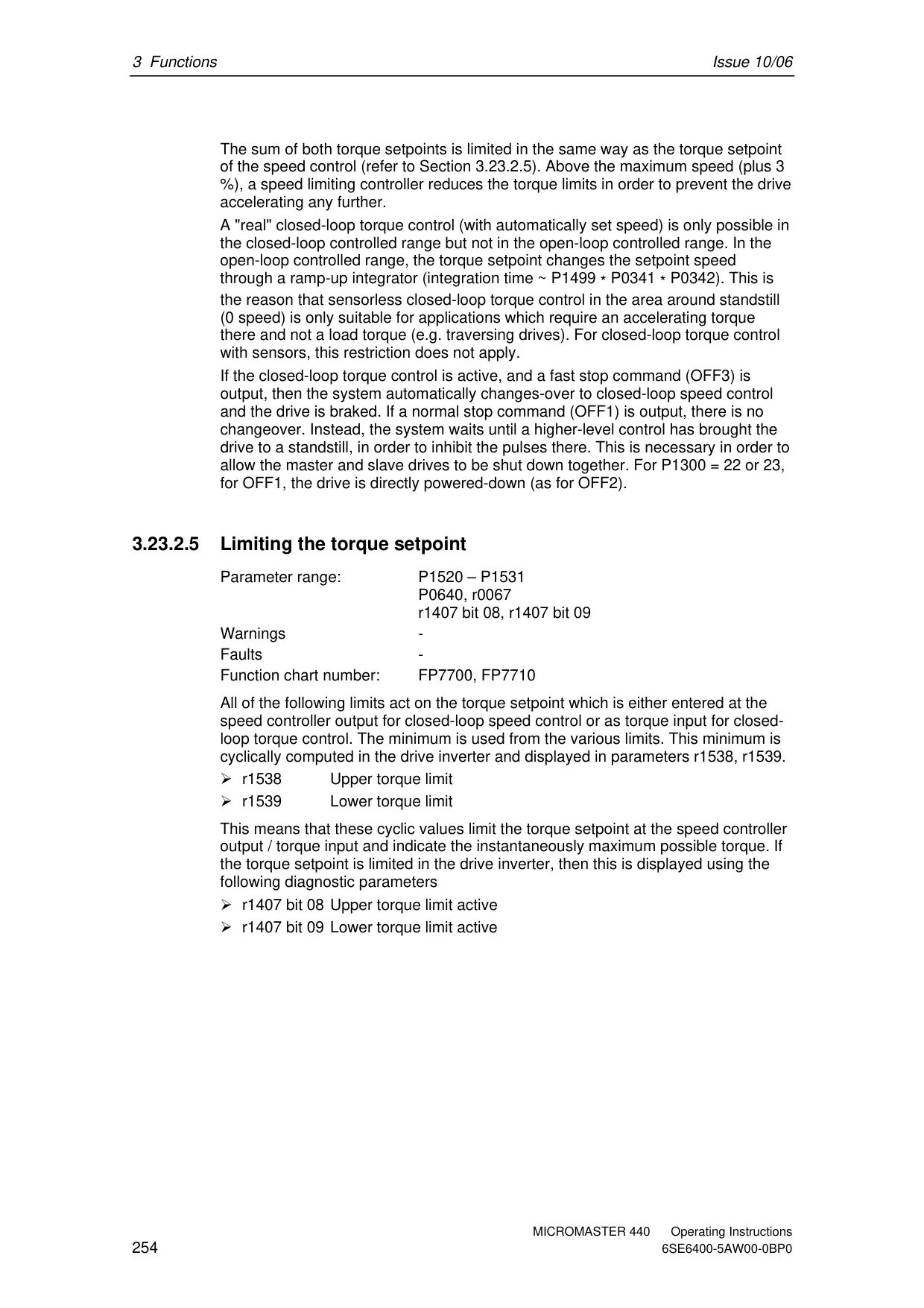
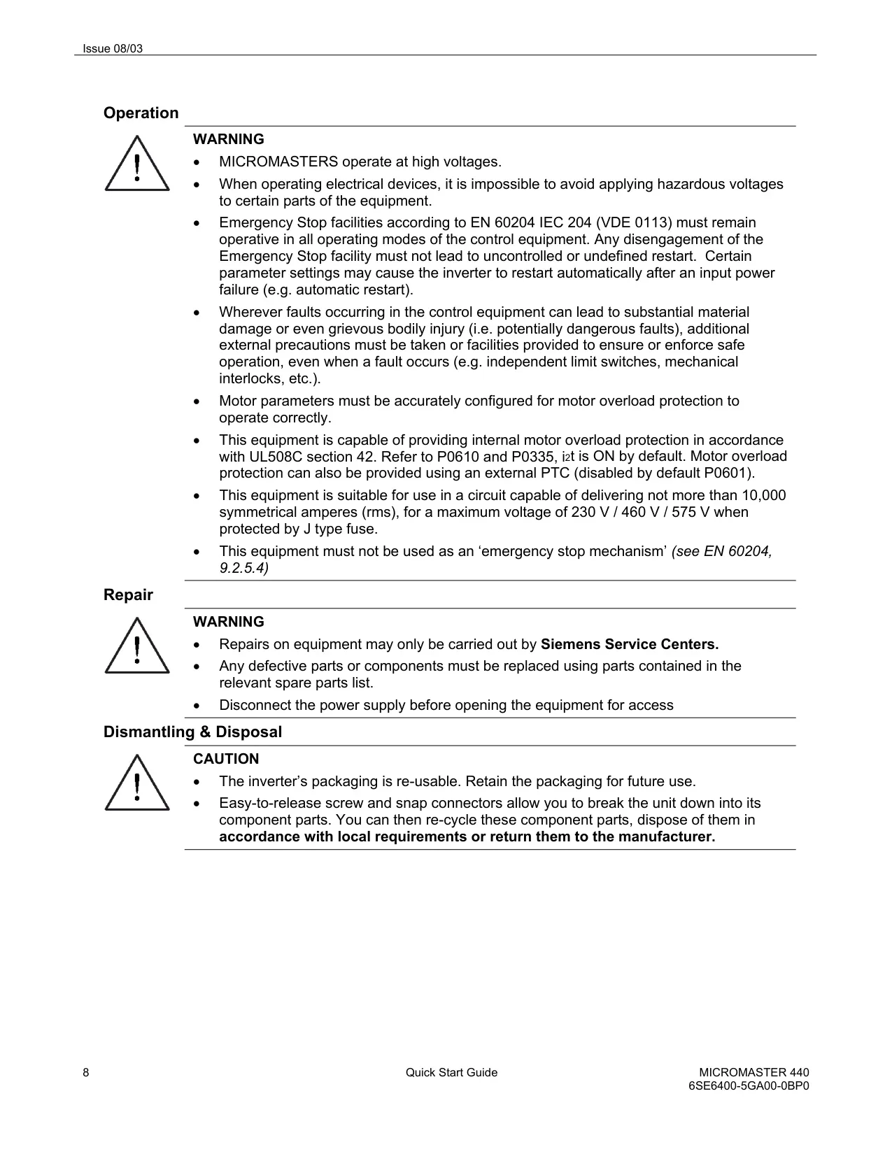
Slip compensation is a vital feature that dynamically adjusts the output frequency to maintain constant motor speed regardless of load variations. For protection, the drive features Fast Current Limitation (FCL), ensuring trip-free operation during sudden load changes, alongside built-in DC injection braking and Compound Braking to enhance stopping performance without external components for smaller frame sizes. Larger frames (FX and GX) utilize external braking choppers for dynamic resistor braking.
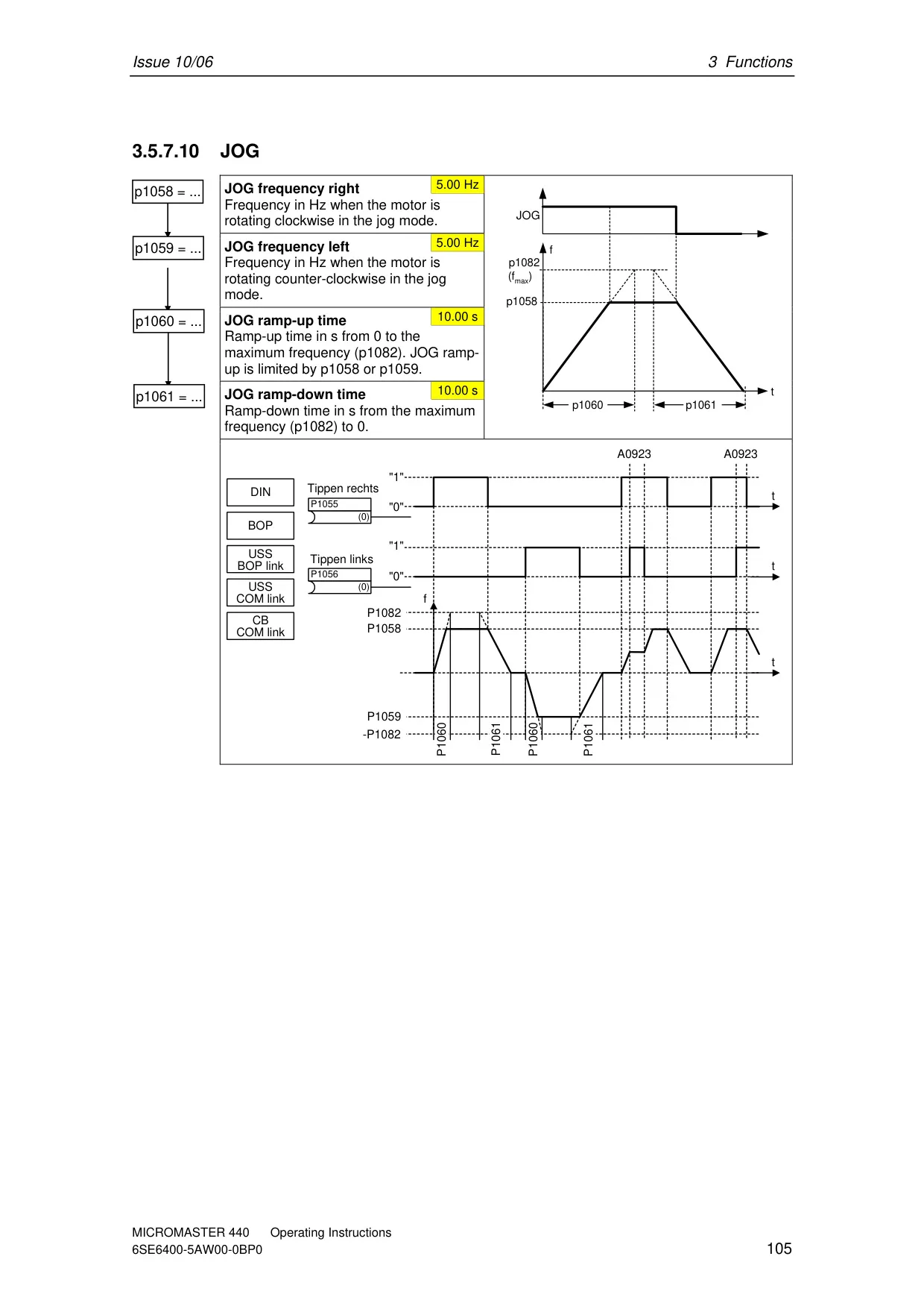
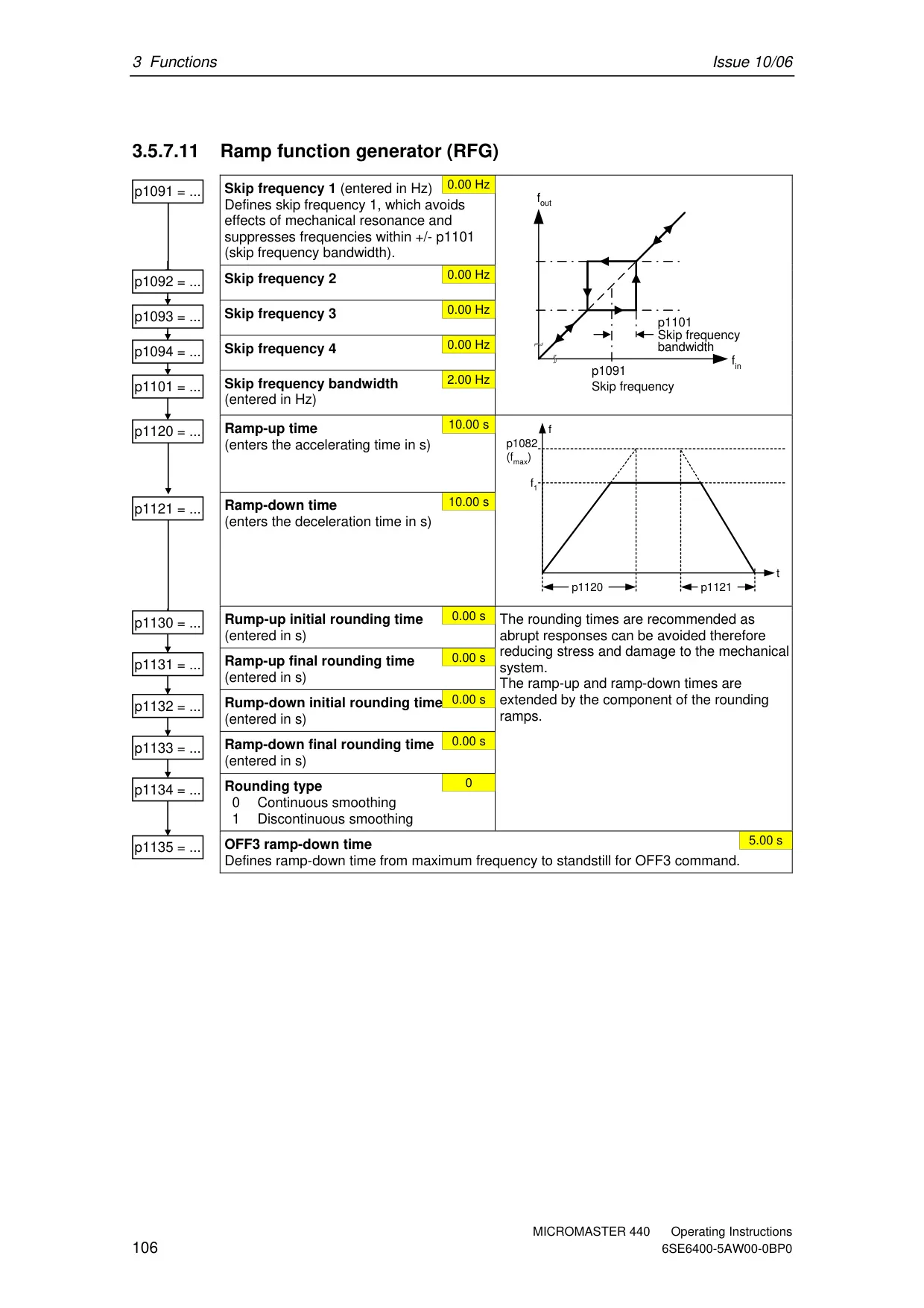
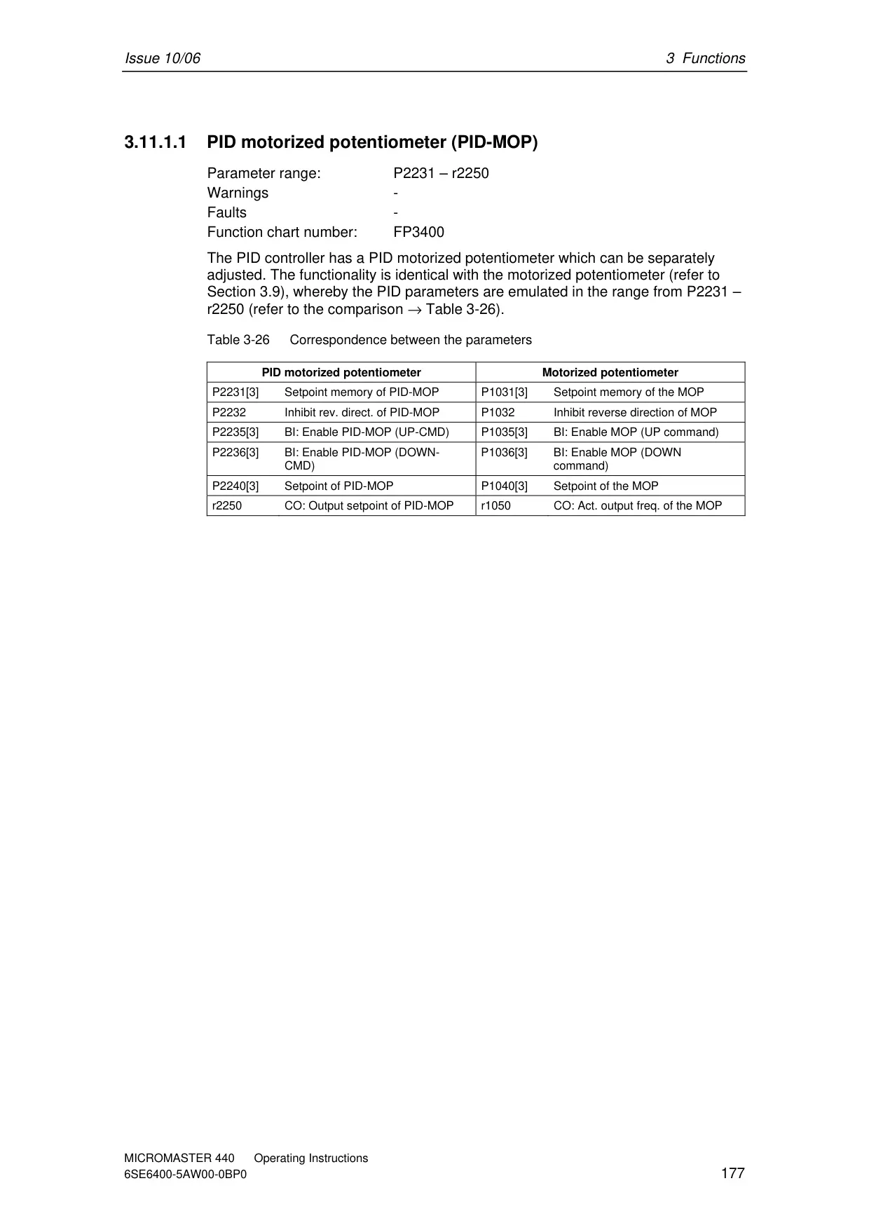
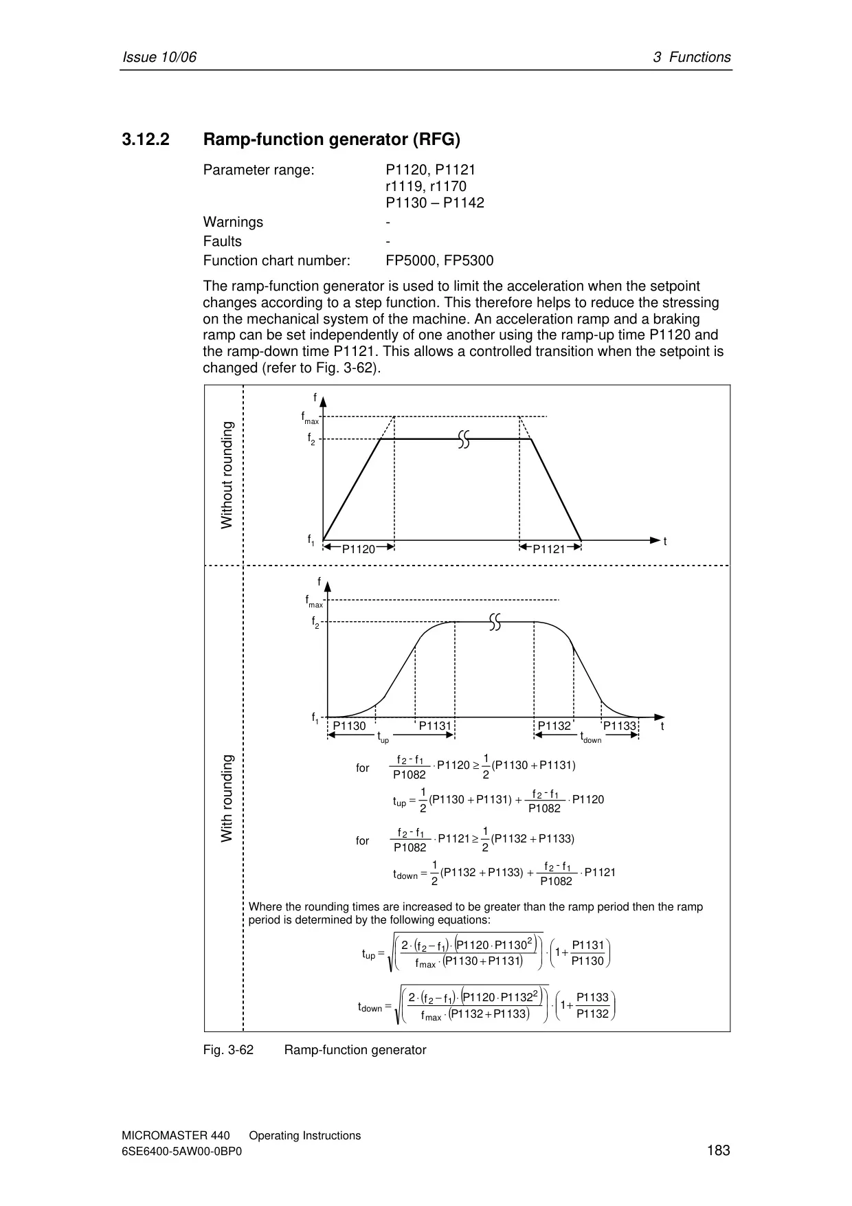
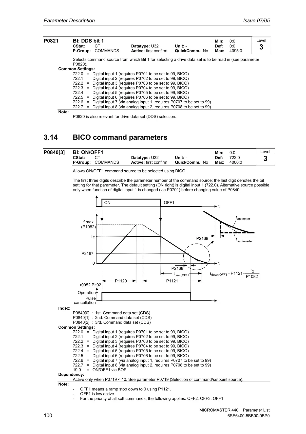
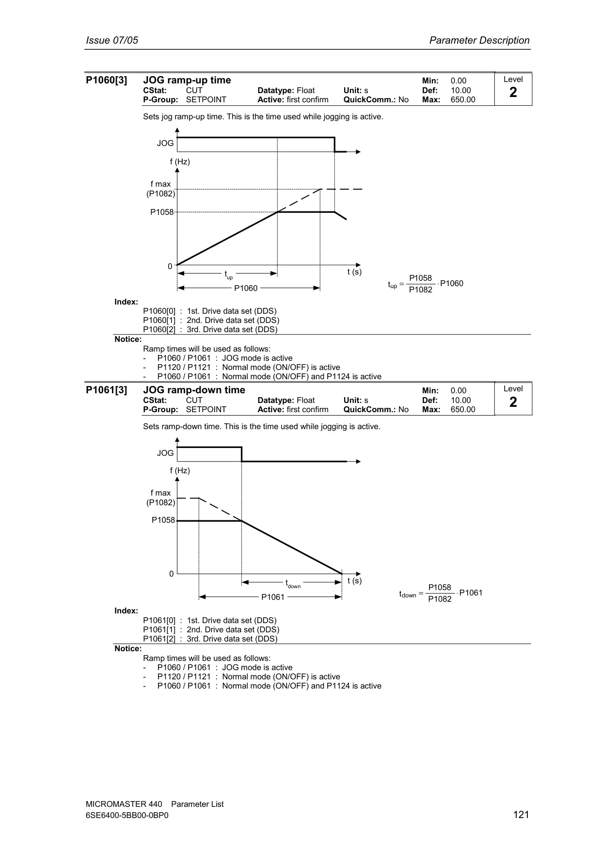
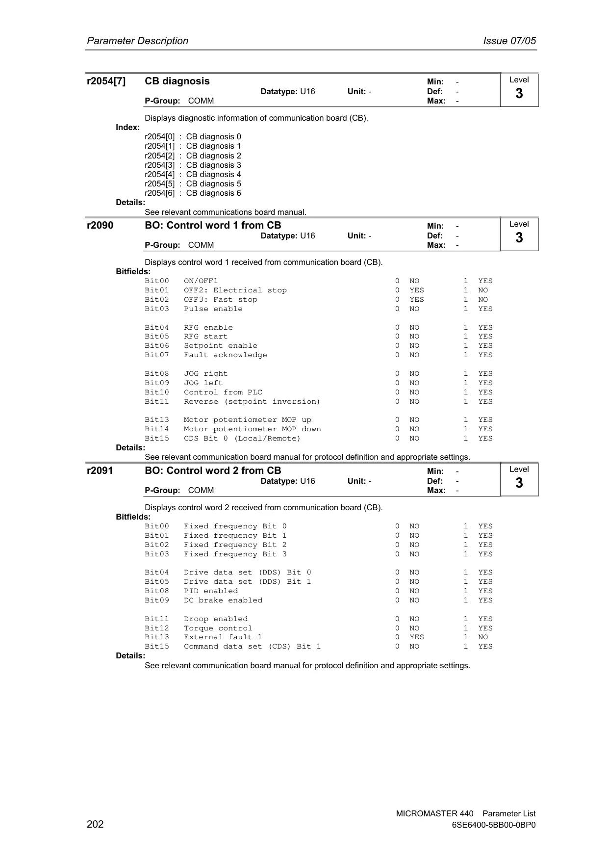
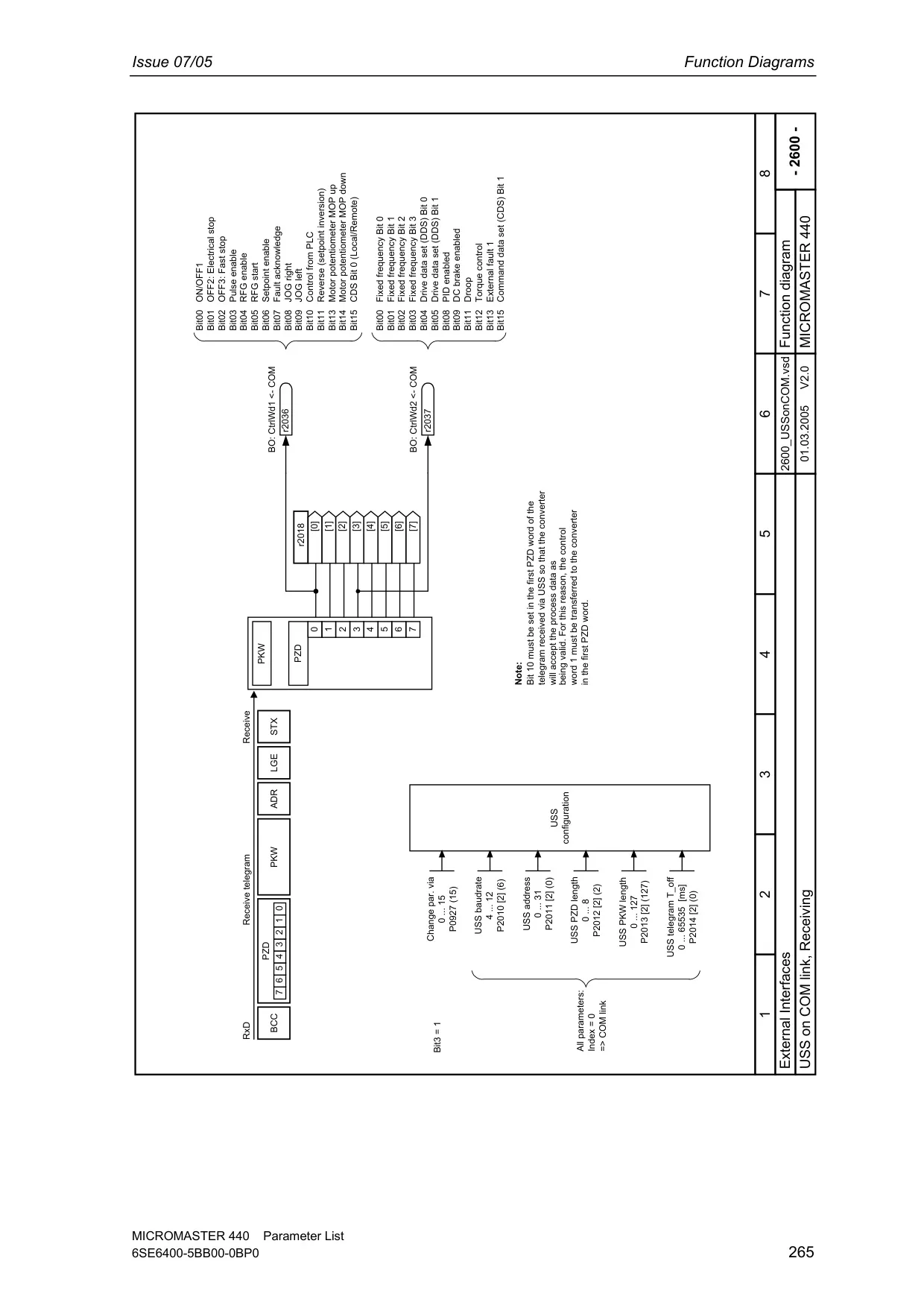
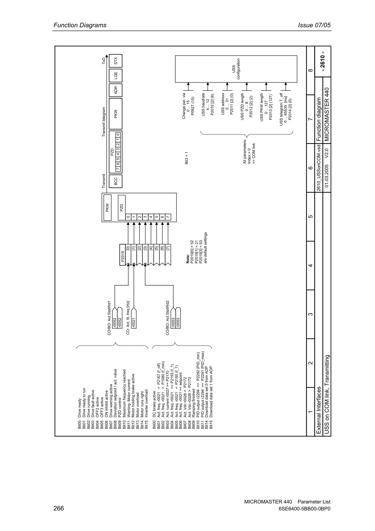
The Micromaster 440 offers extensive flexibility in setpoint input, accepting commands via analog inputs, a communication interface, JOG function for incremental movements, a Motorized Potentiometer (MOP) for gradual speed adjustments, or predefined Fixed Frequencies. Its Ramp Function Generator allows for configurable acceleration and deceleration times, with optional smoothing to reduce mechanical stress and vibrations, ensuring a "soft" start and stop.
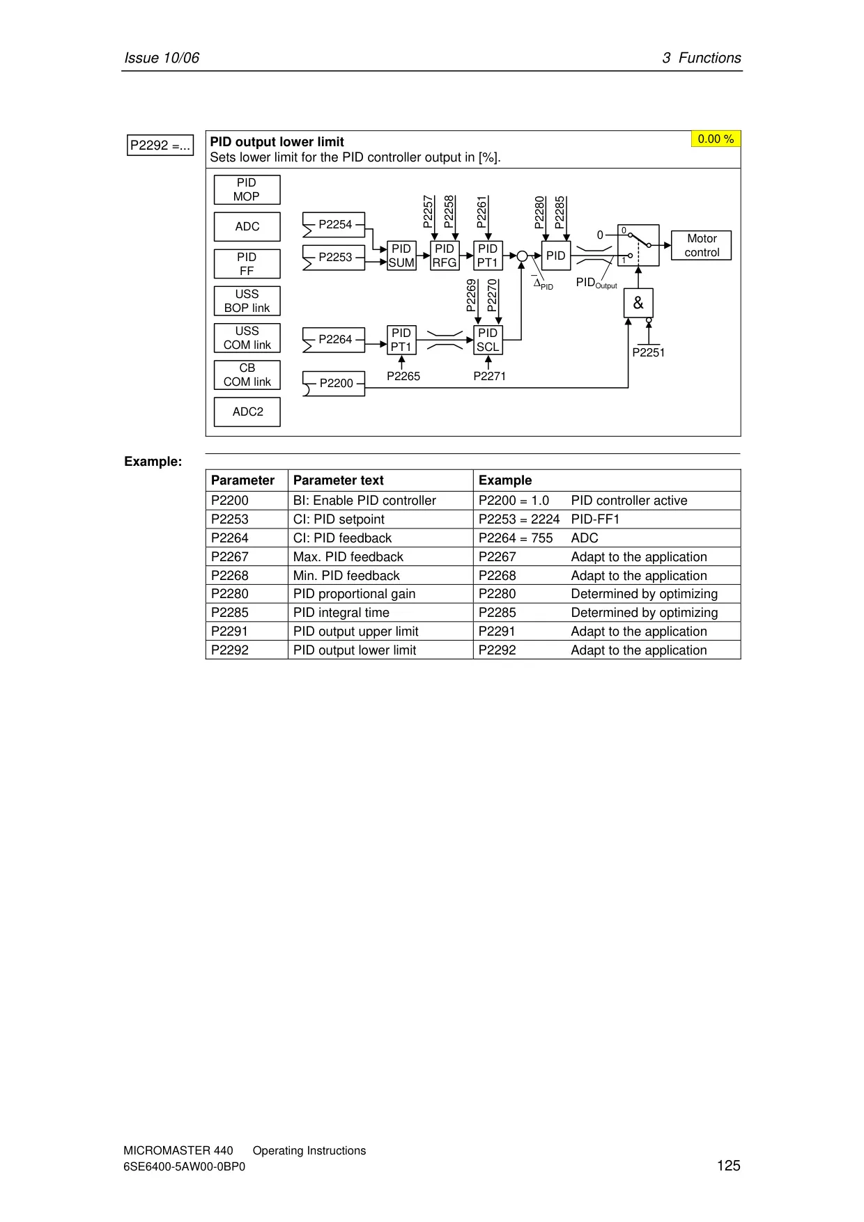
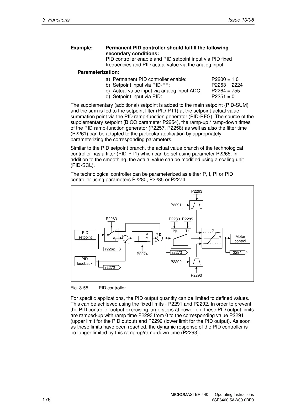
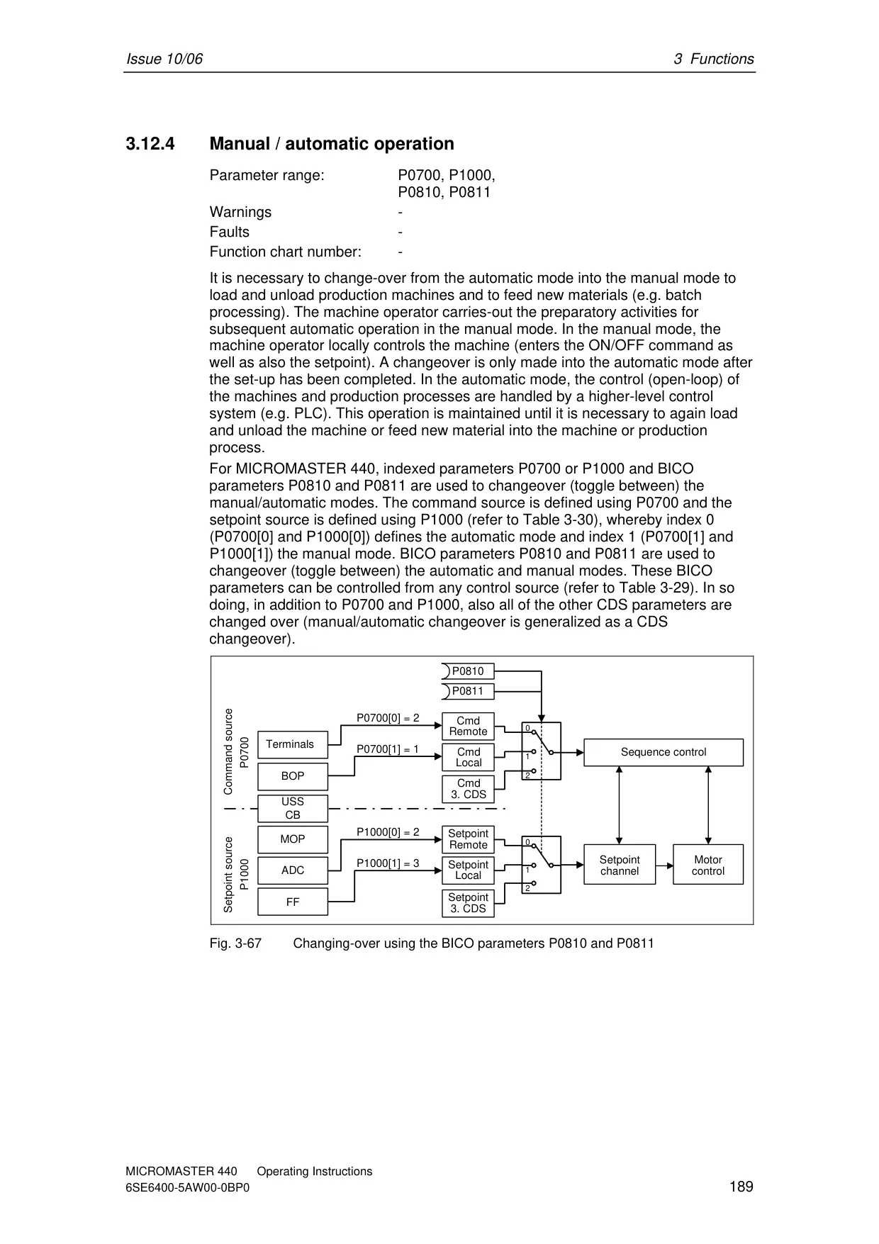
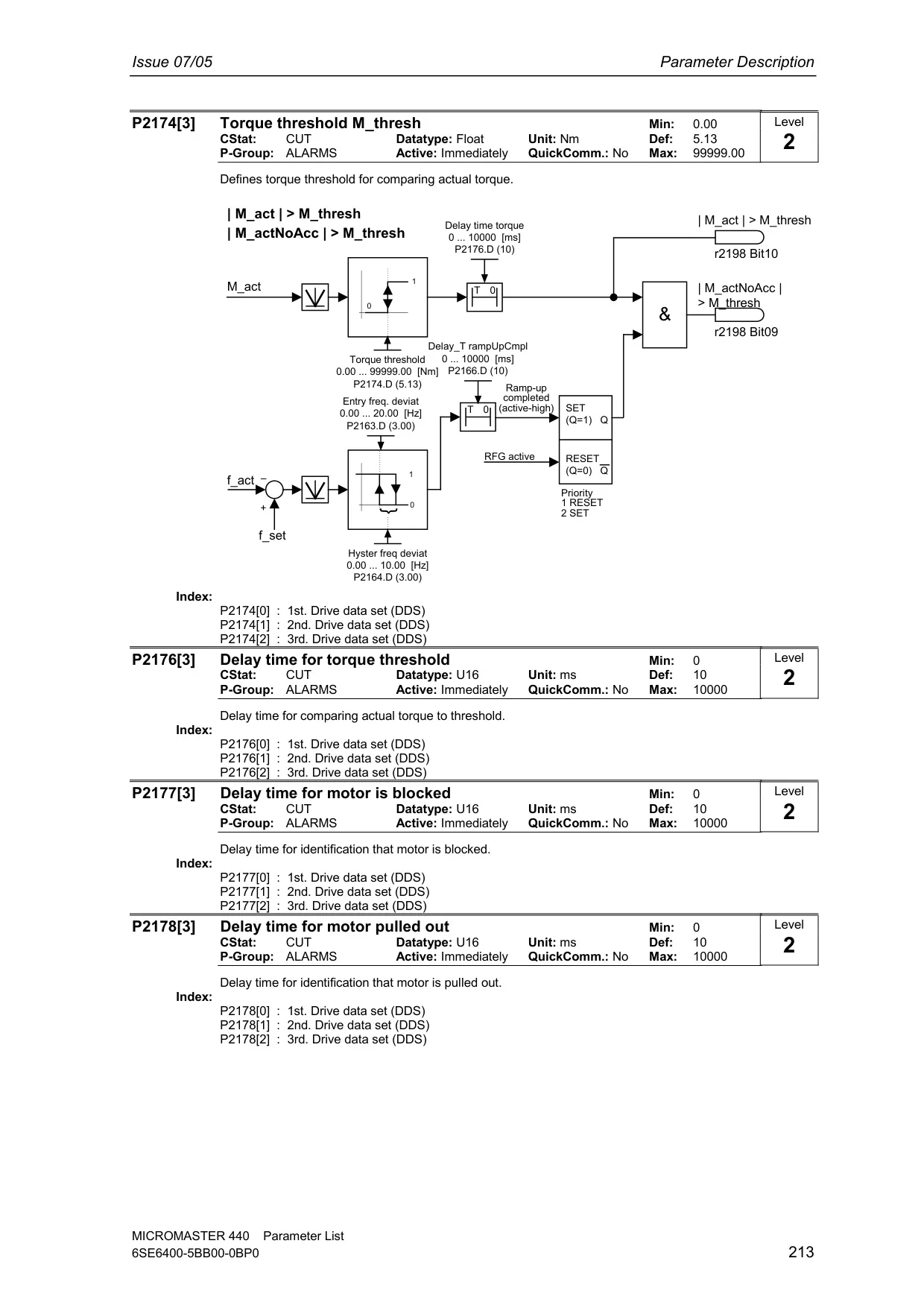
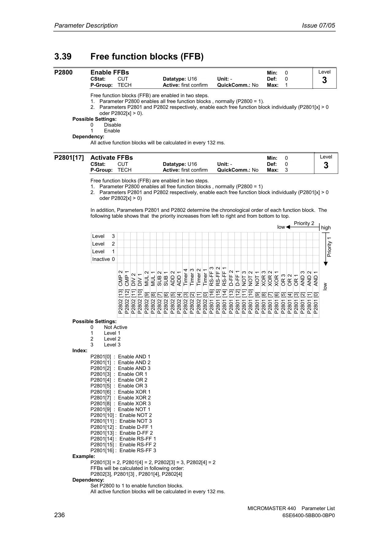
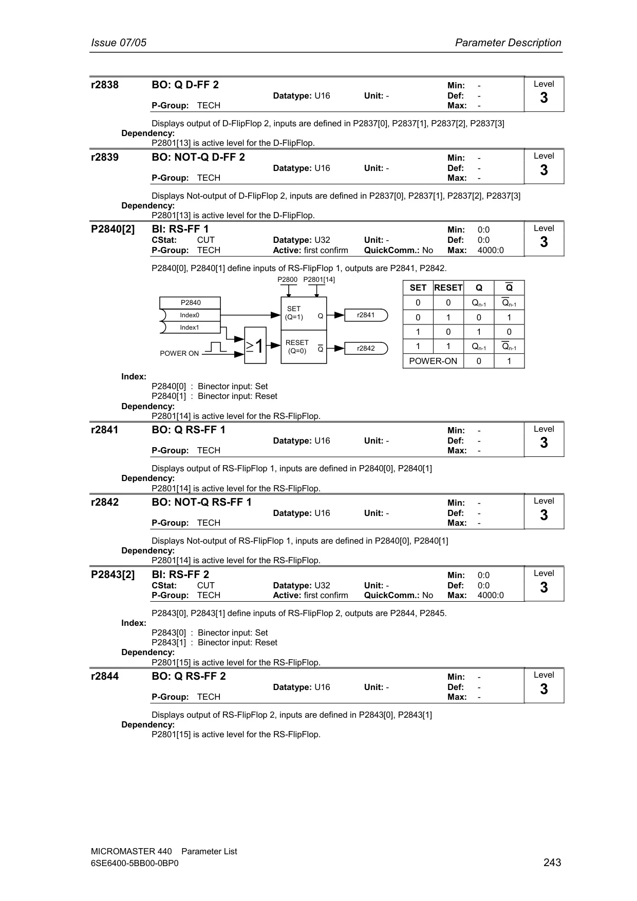
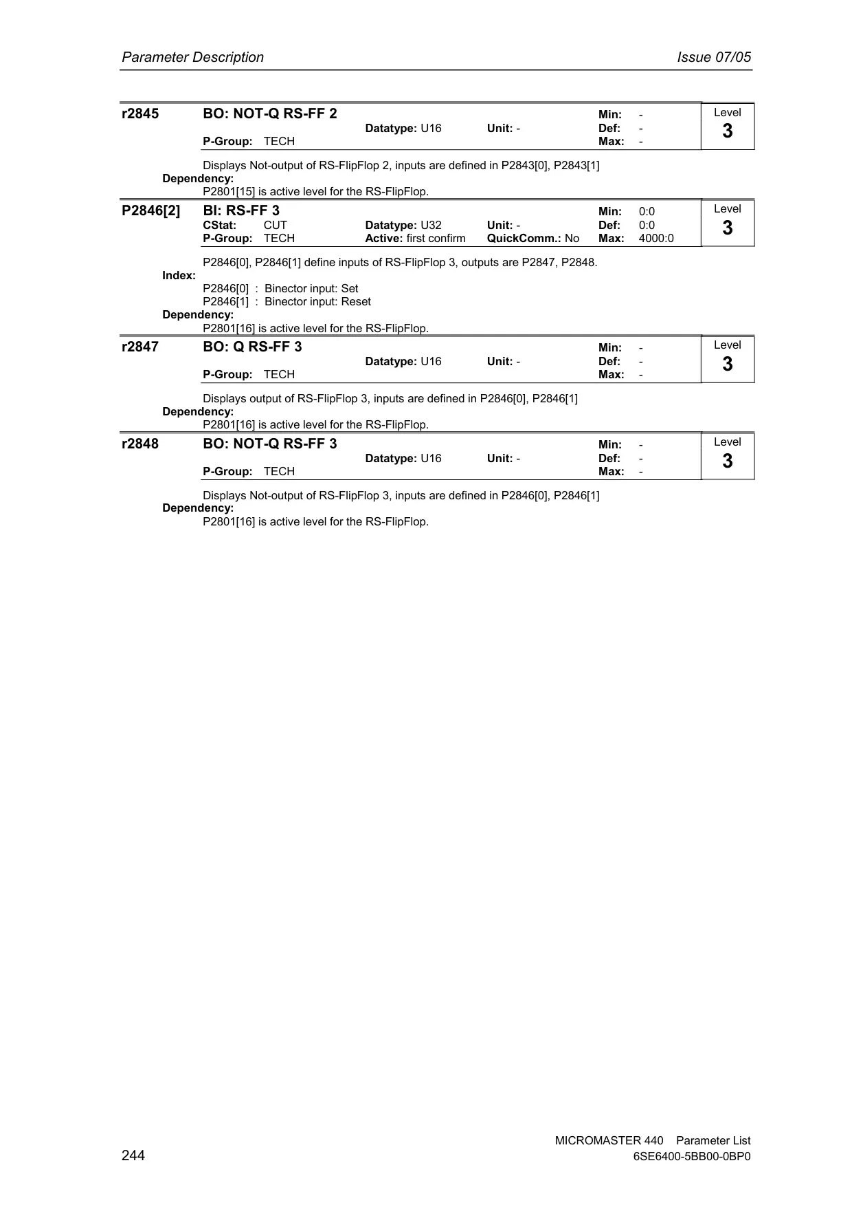
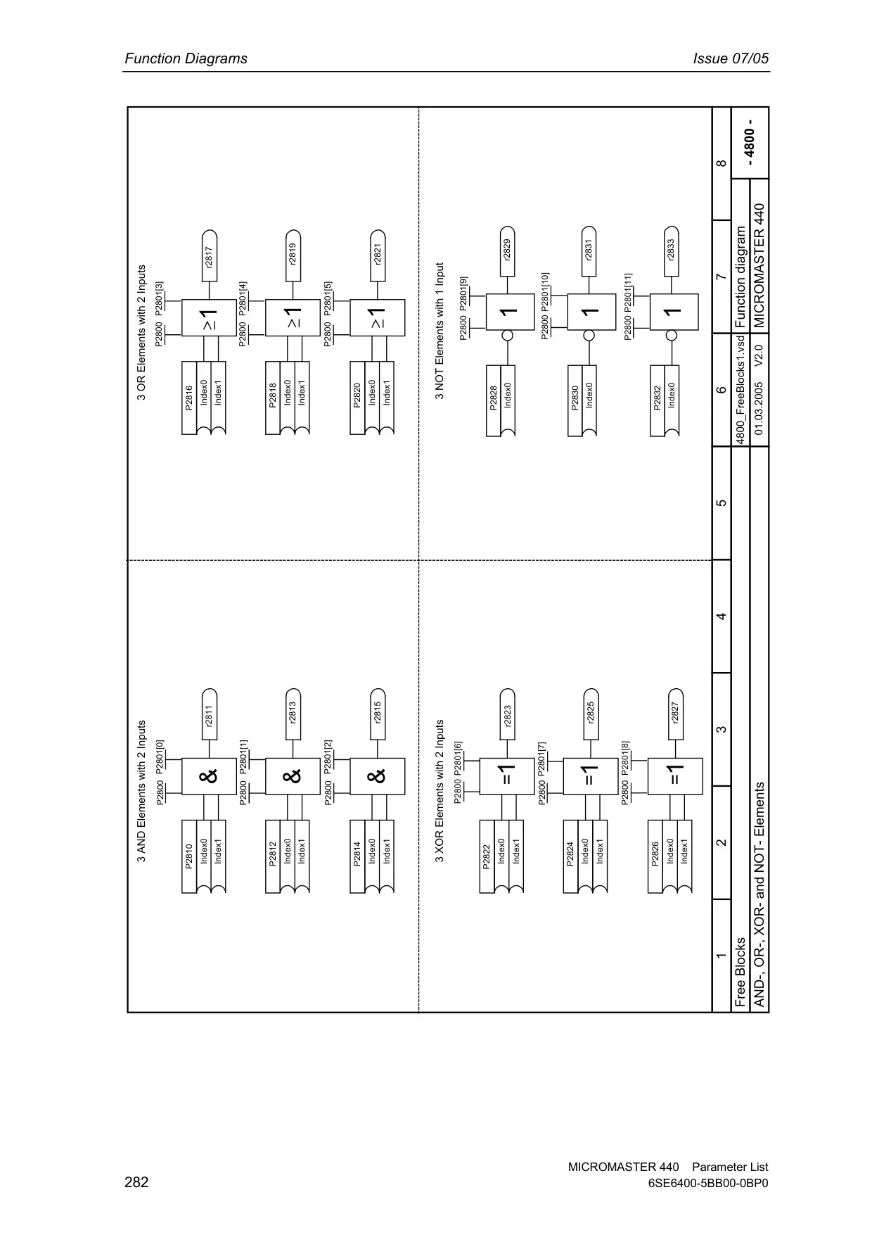
For advanced process control, an integrated Technology Controller (PID) is available, capable of controlling external process variables such as pressure, level, or temperature, thus expanding the VFD's utility beyond basic motor control. The drive also supports Parameter Set Switch-over (Command Data Sets (CDS) and Drive Data Sets (DDS)), enabling quick transitions between different motor or control configurations. Furthermore, Free Function Blocks (FFB) provide programmable logic and arithmetic operations, allowing users to implement custom interlocking or control strategies directly within the drive.
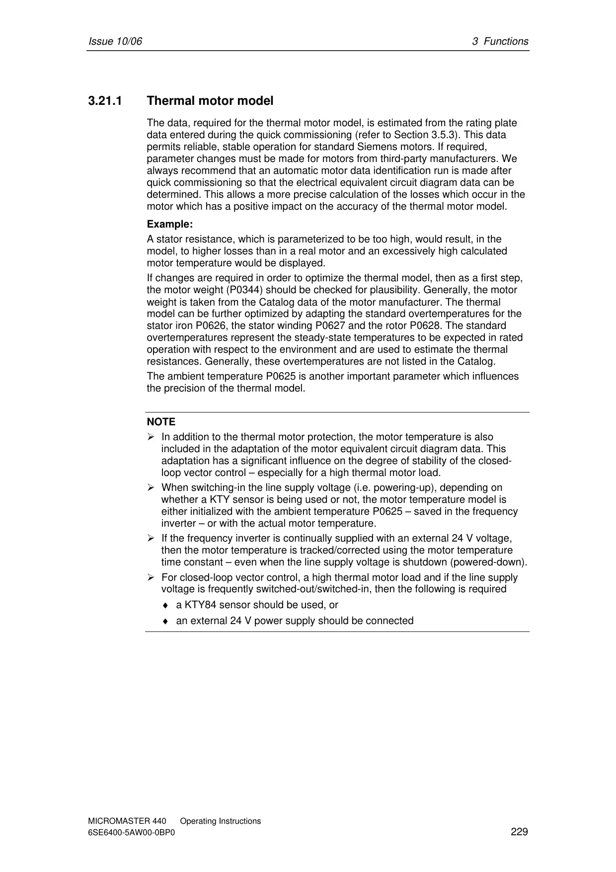
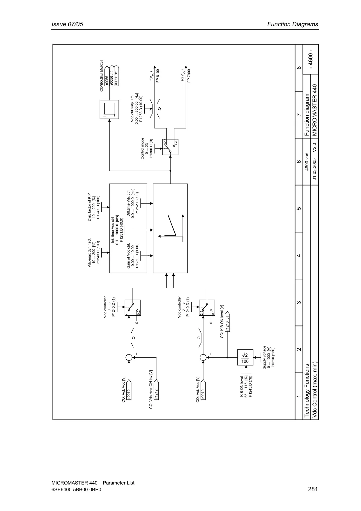
DC Link Voltage Control and Kinetic Buffering (Vdc_min controller) are crucial for maintaining stable operation, buffering brief line supply dips by leveraging the driven load's kinetic energy. Positioning Ramp Down facilitates precise stopping by generating a continuous braking ramp based on an external trigger. Comprehensive protection includes i²t thermal motor protection and inputs for external PTC/KTY84 sensors, guarding against overheating.
Frequently Asked Questions (FAQs)
Can't find the answer you need? Here are some frequently asked questions about the Siemens Micromaster 440 Variable Frequency Drive, and we answer them below.