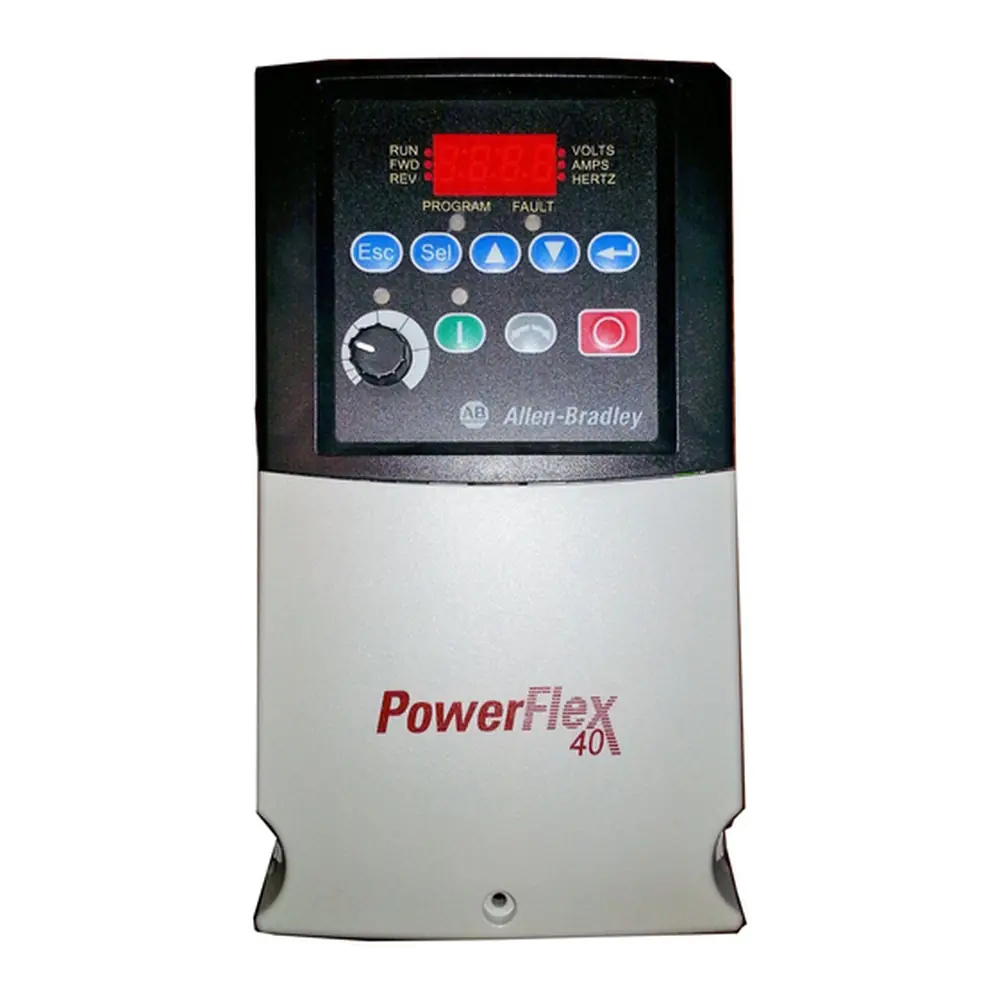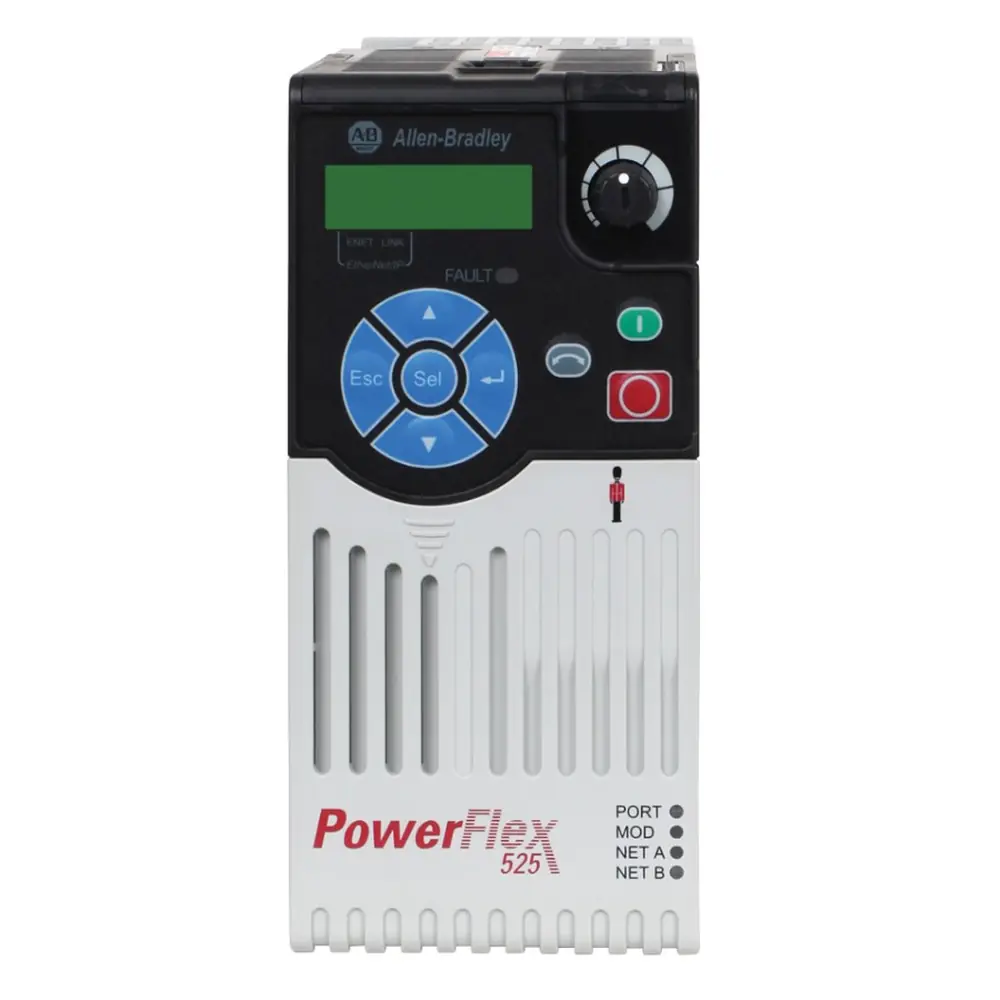
Allen-Bradley Powerflex 4M VFD Instruction Manual
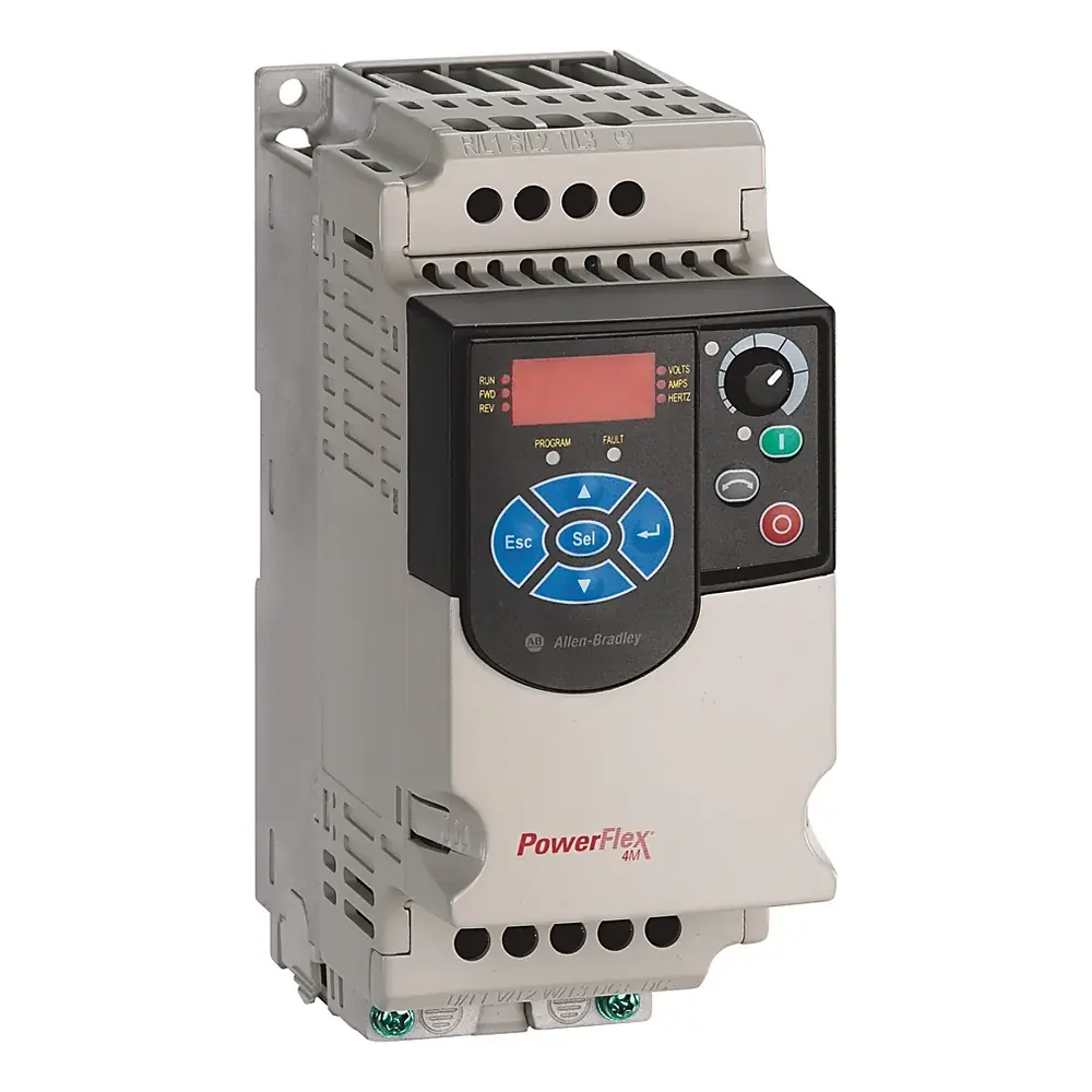
Allen-Bradley Powerflex 4M VFD

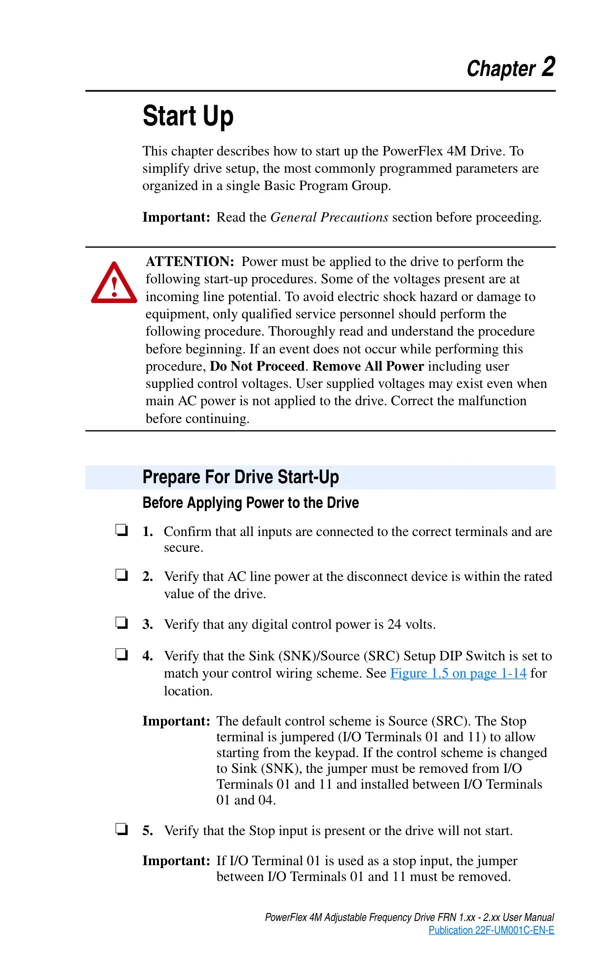
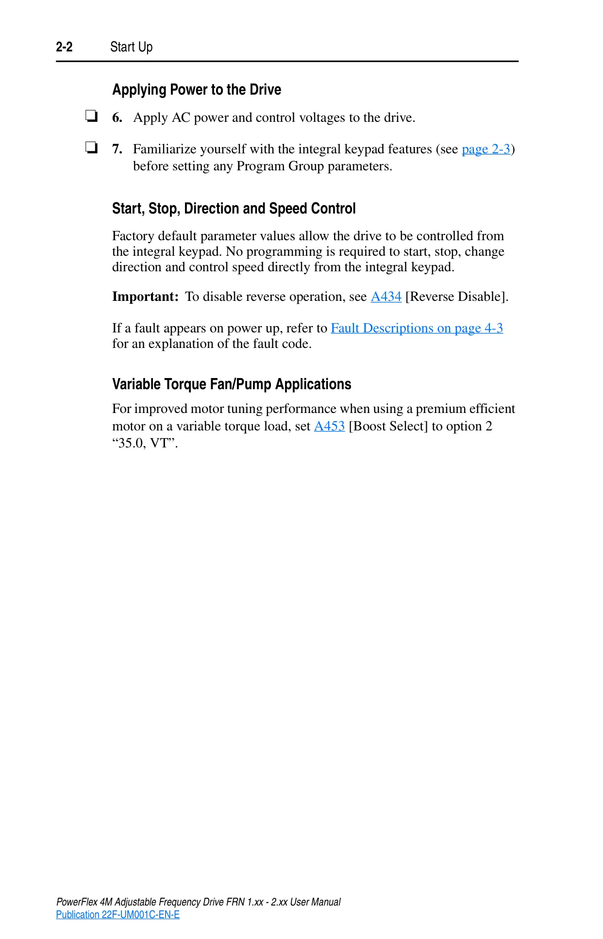



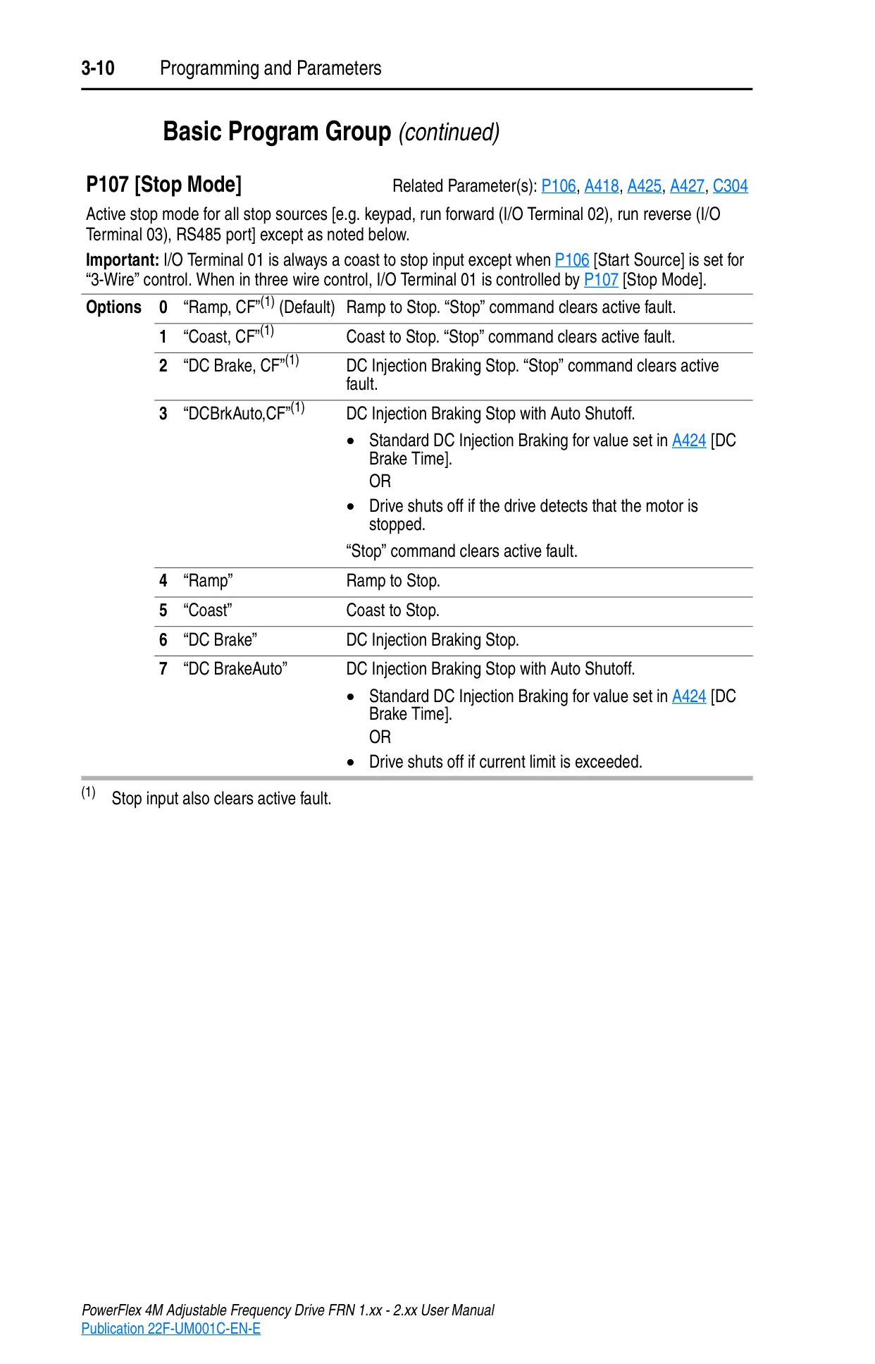
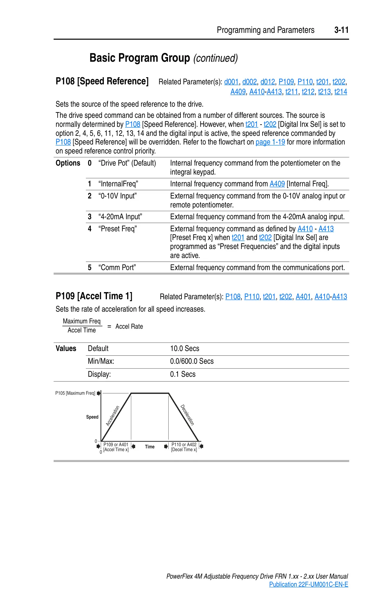
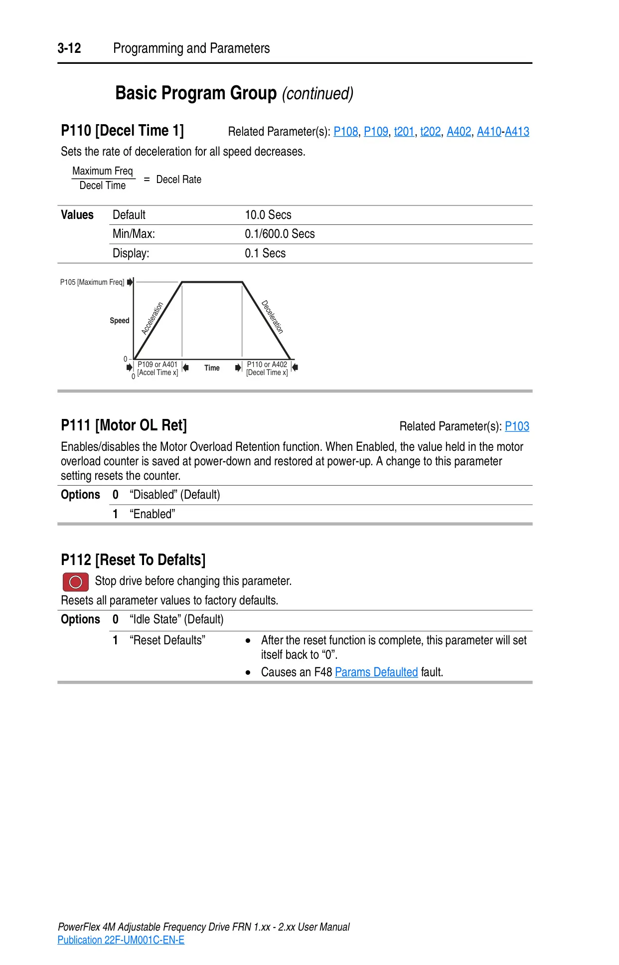
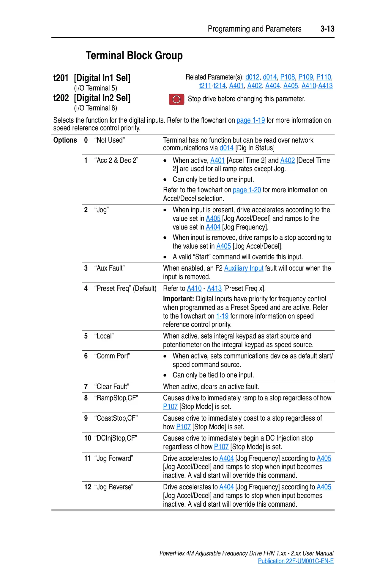
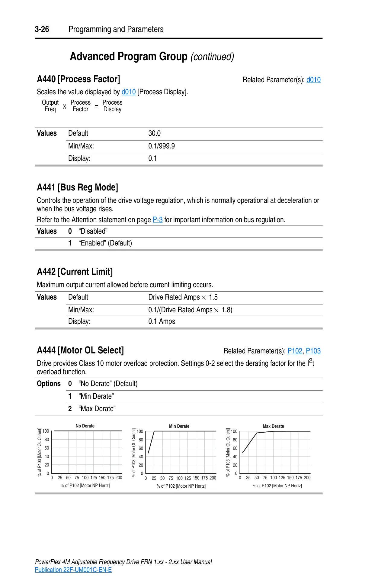
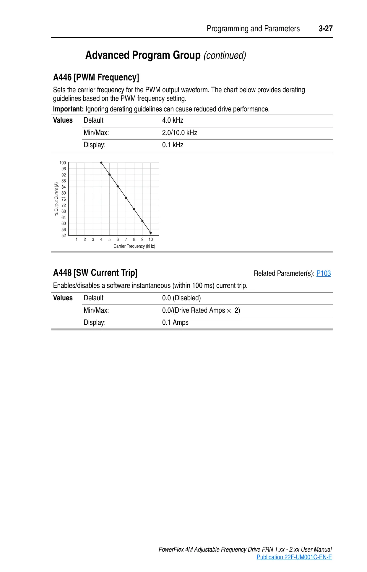
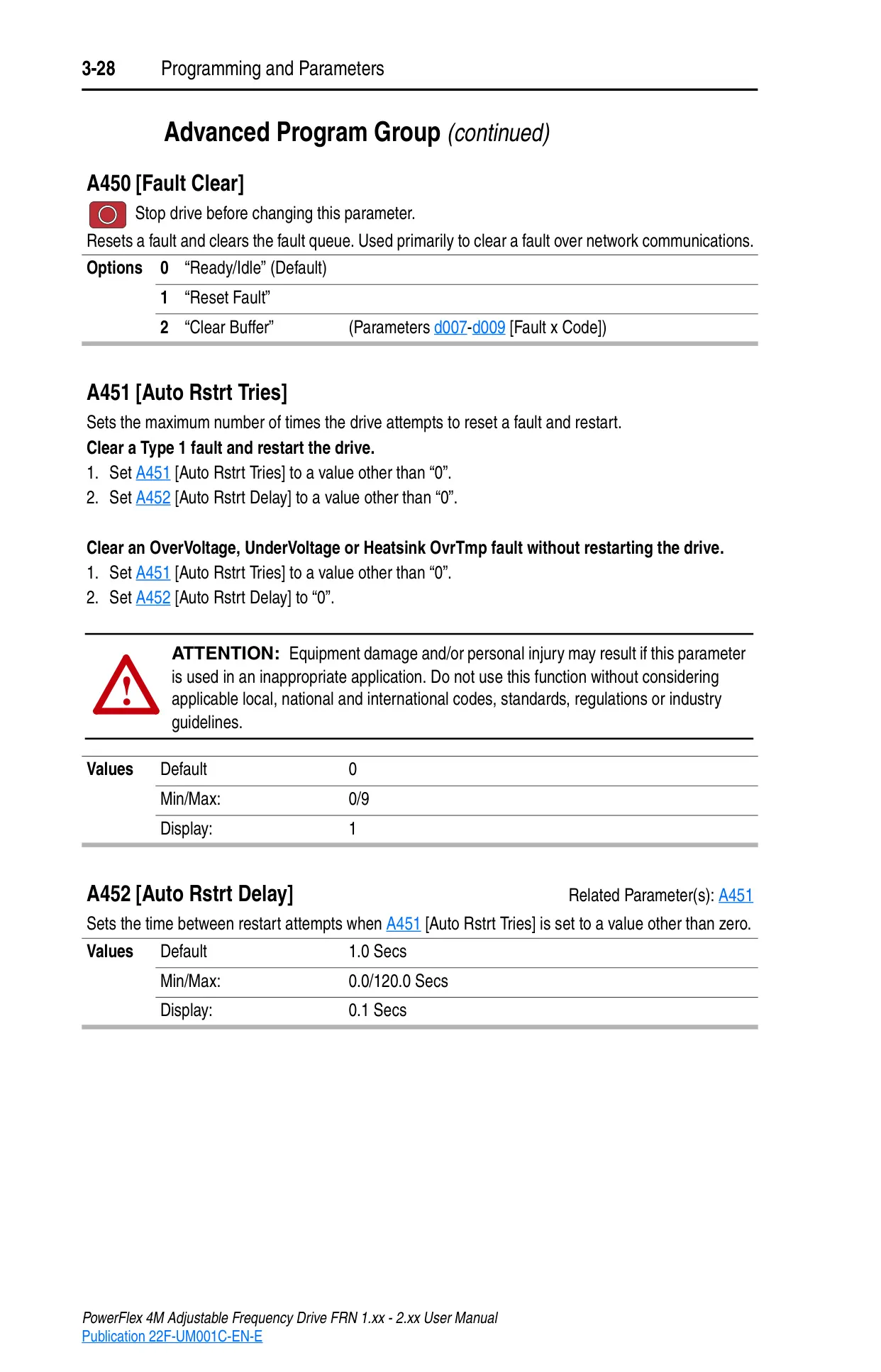
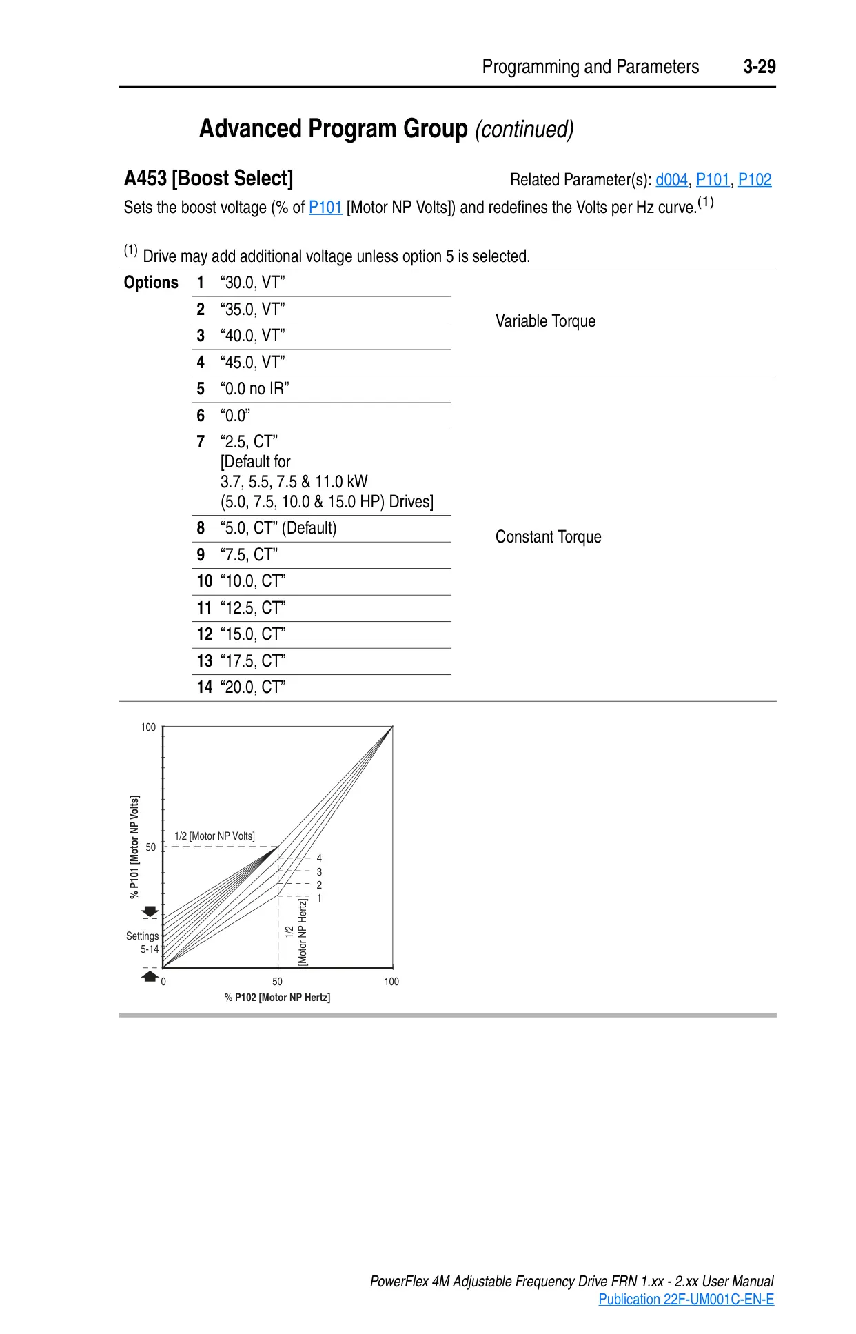

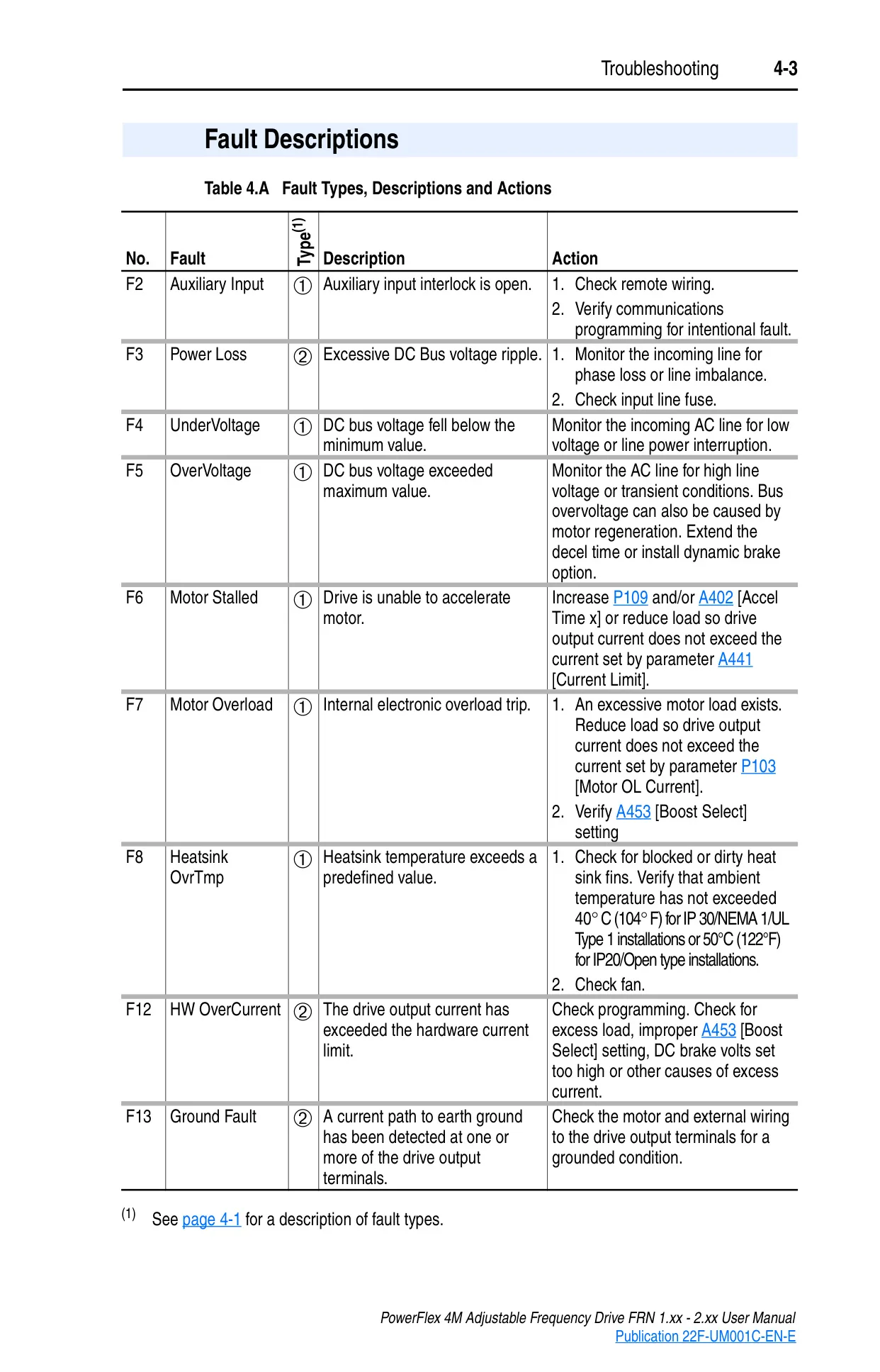
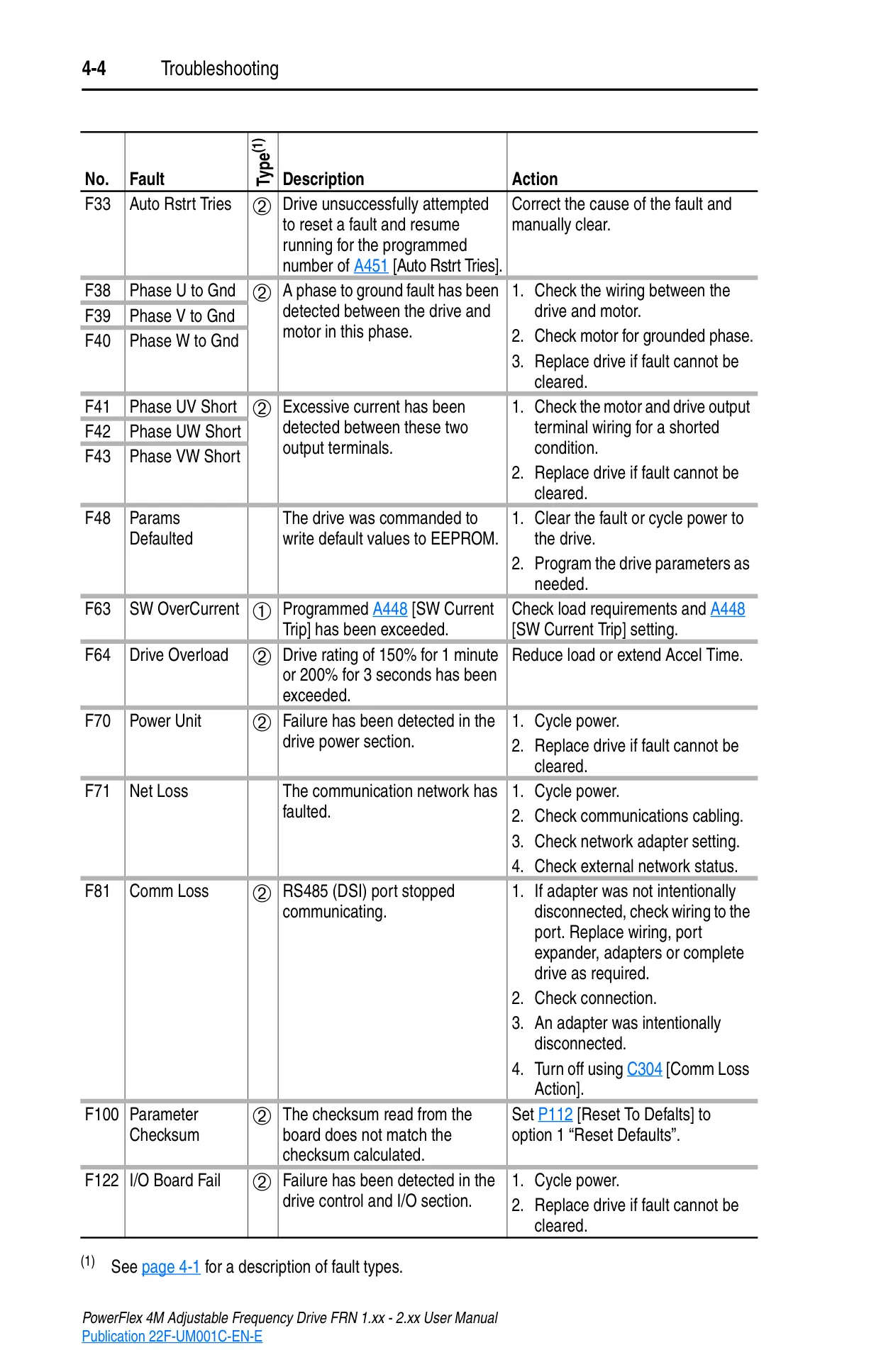
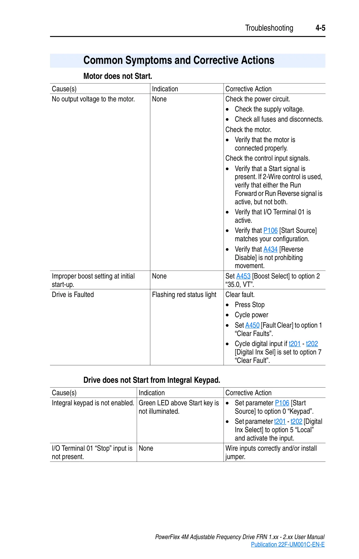
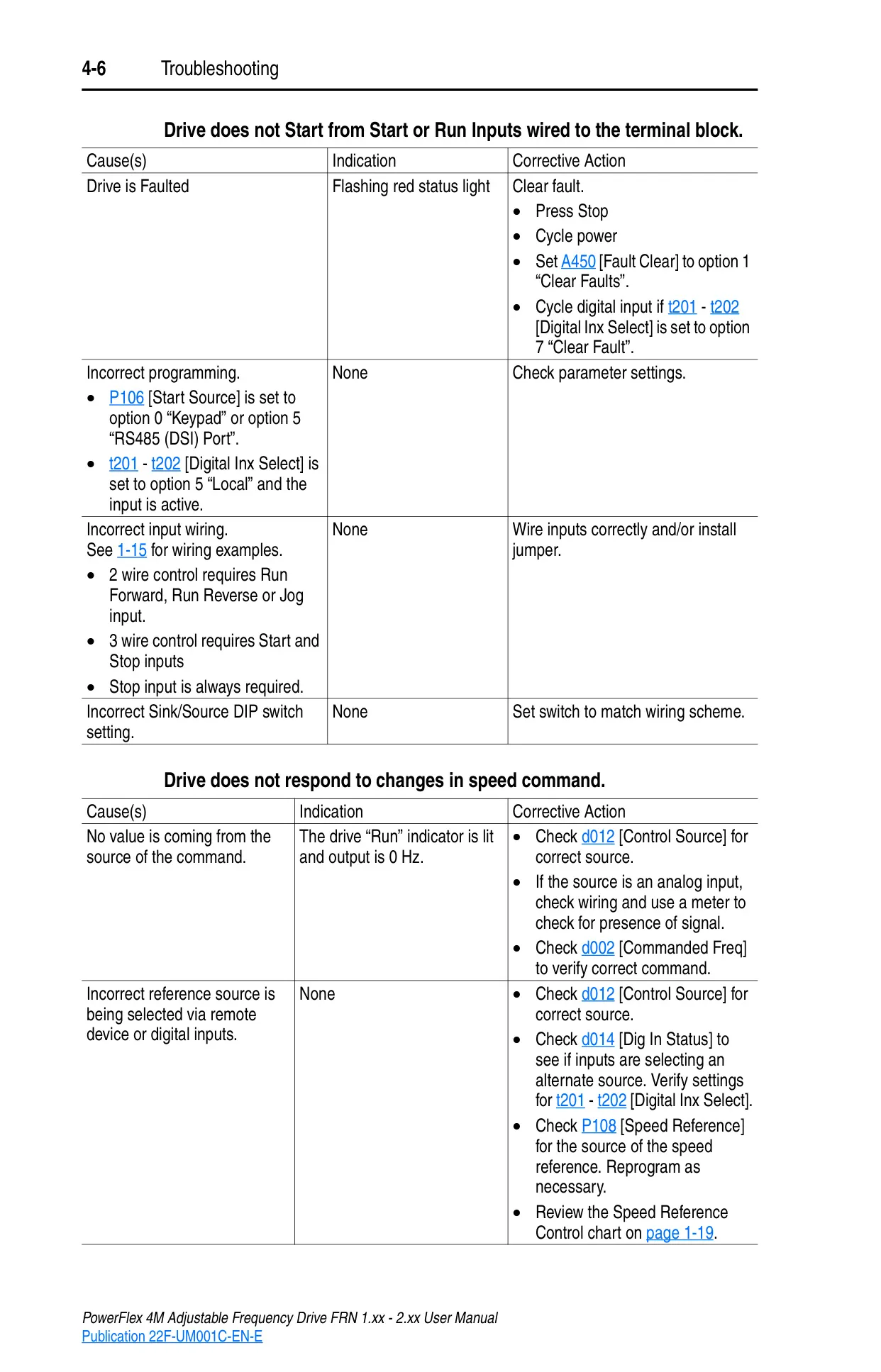
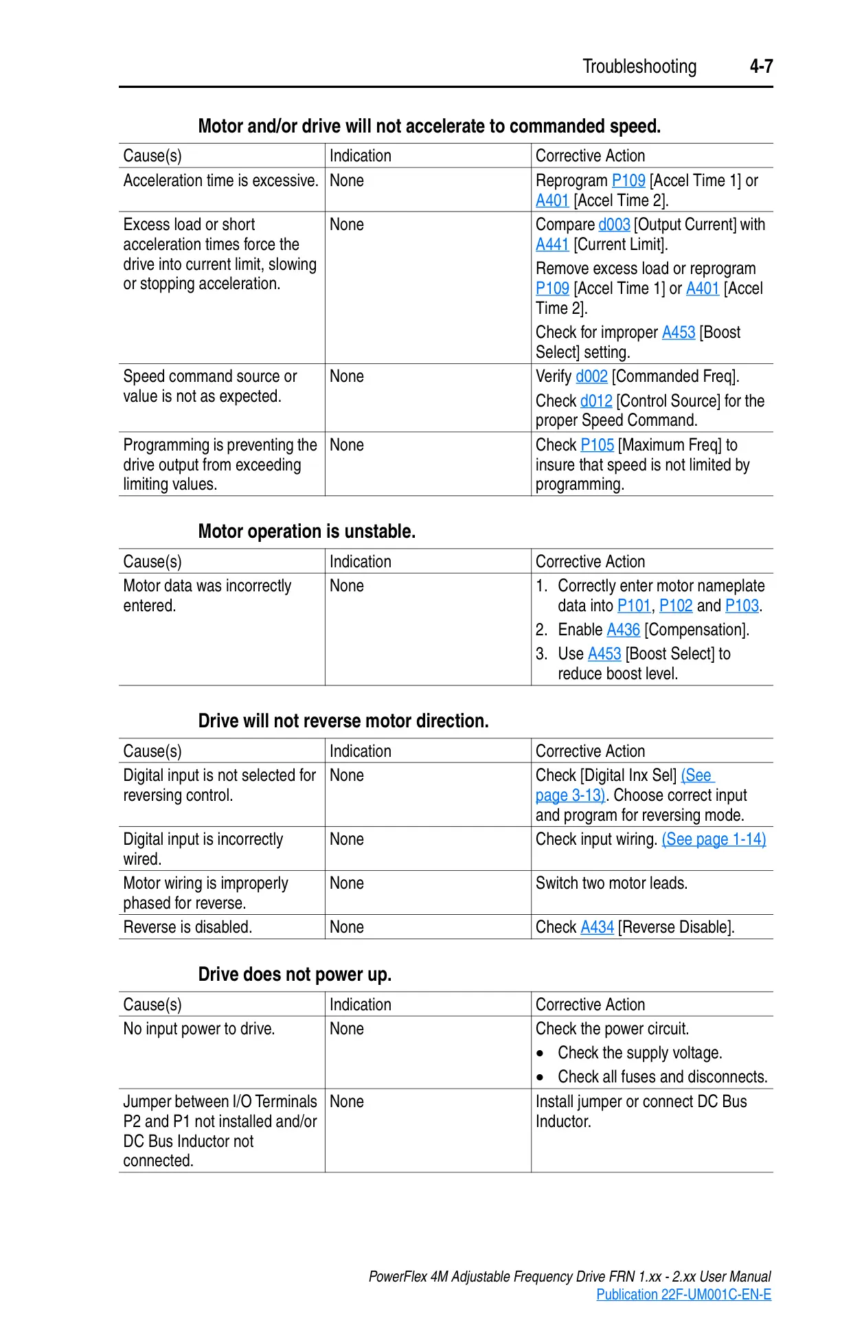

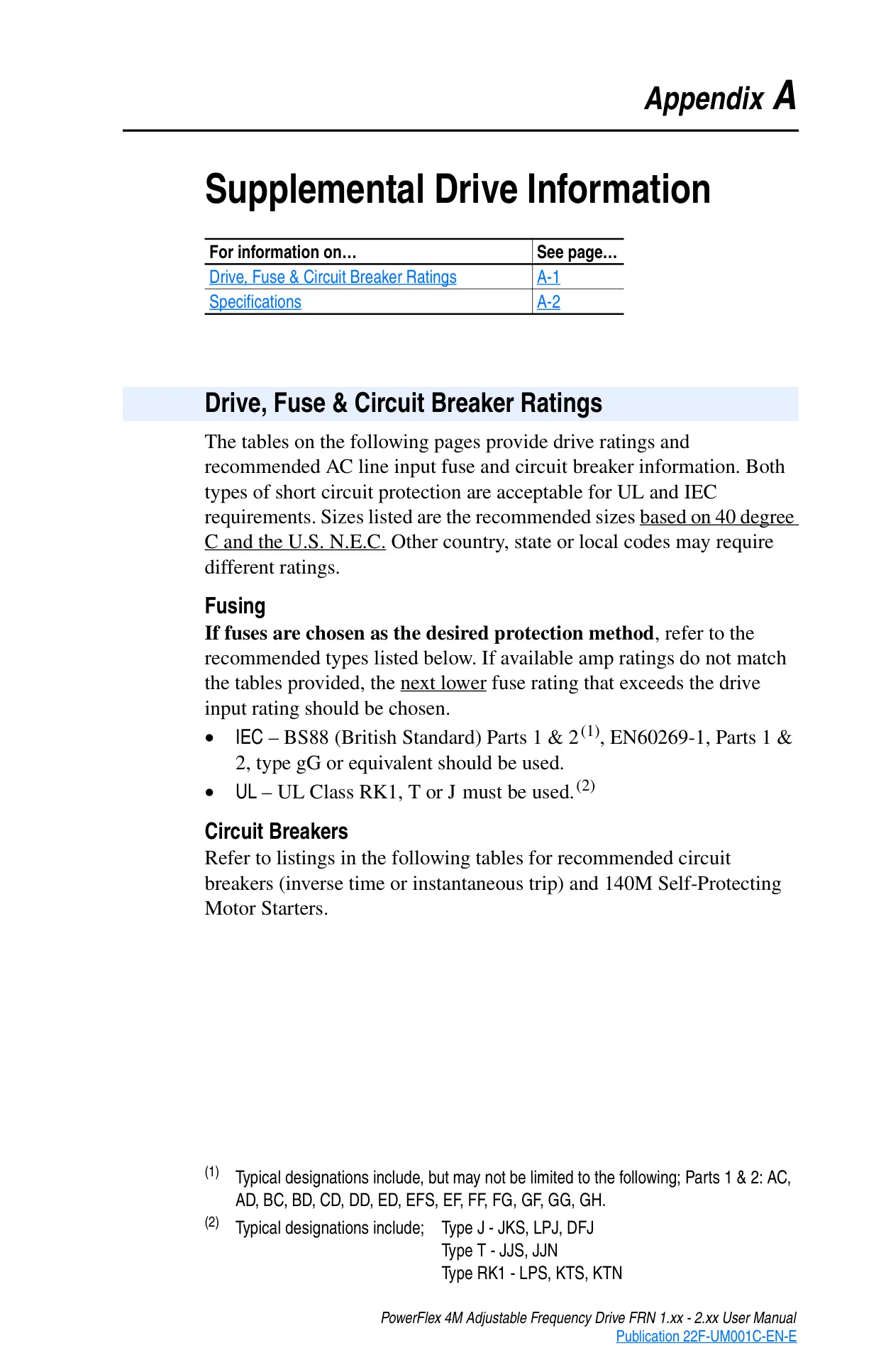








Allen-Bradley Powerflex 4M VFD





Allen-Bradley Powerflex 4M VFD
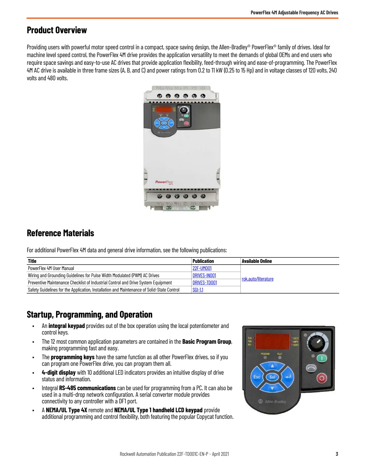
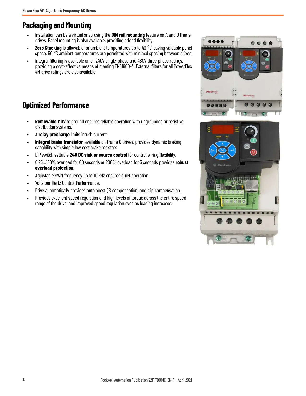
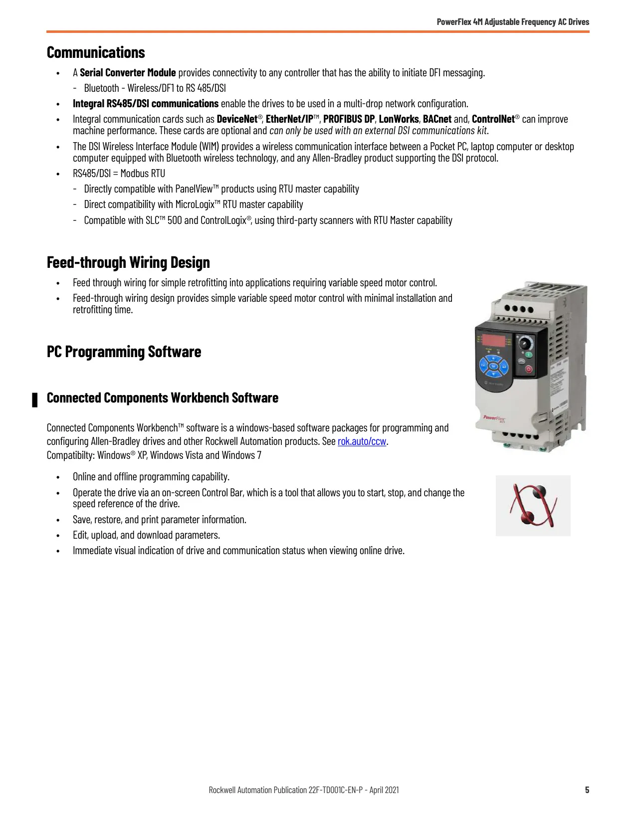

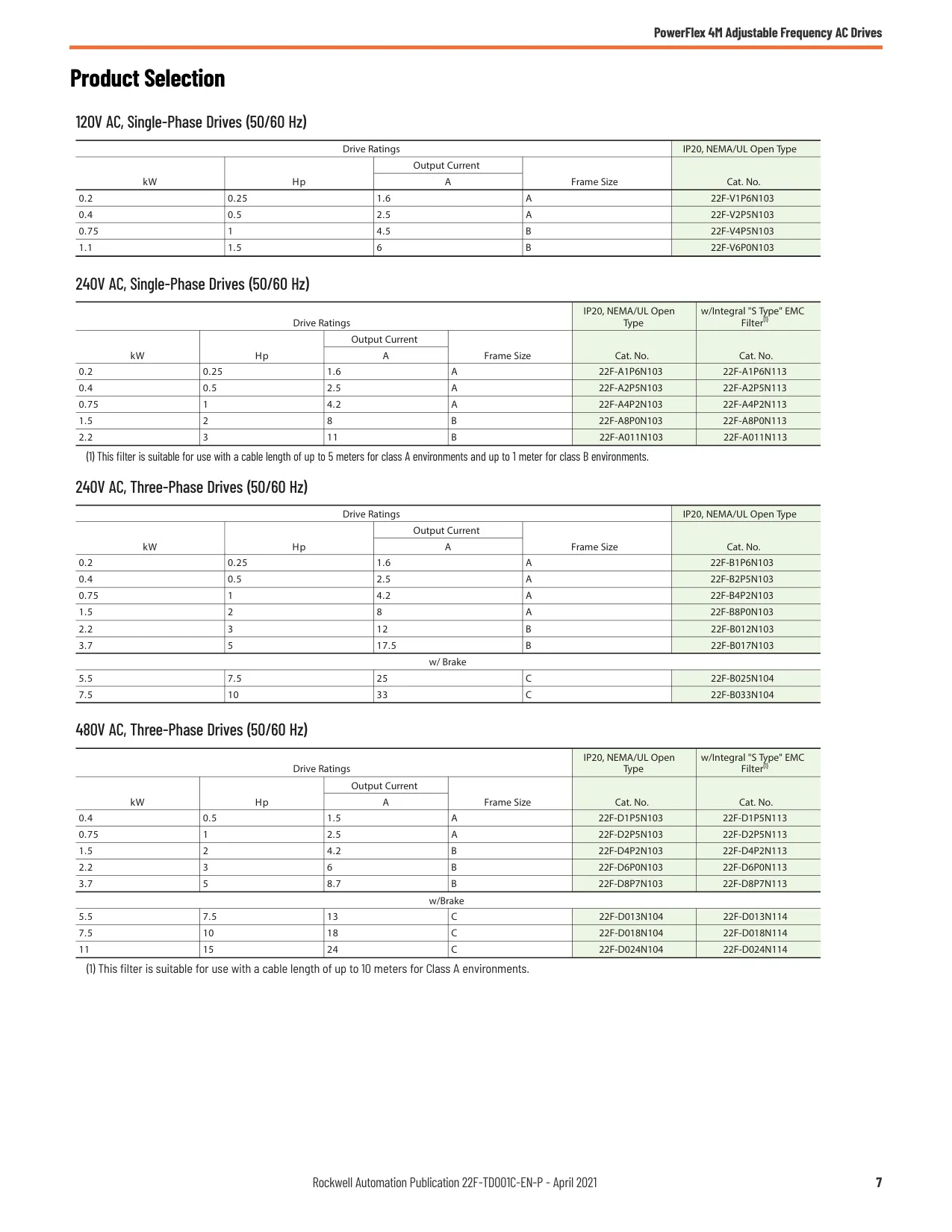
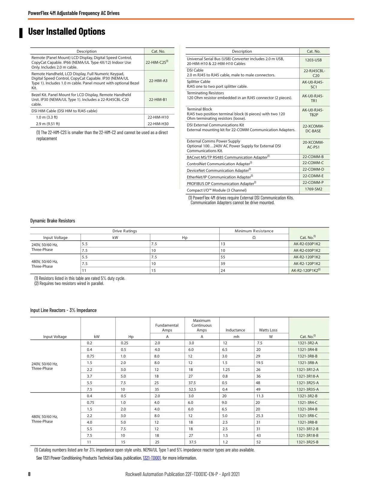
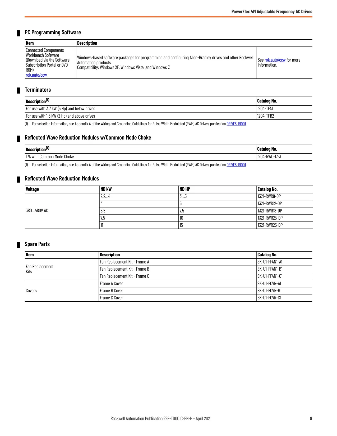


Allen-Bradley Powerflex 4M Instructions
Here we offer the Allen-Bradley Powerflex 4M VFD manual completely free and in English. We have cataloged this manual in the Variable Frequency Drives section on Manualverse, and it has been rated by 1 users with an average rating of 5. If you have any specific questions about Allen-Bradley Powerflex 4M VFD, we suggest checking the Frequently Asked Questions (FAQs) section of this manual.
Product Images


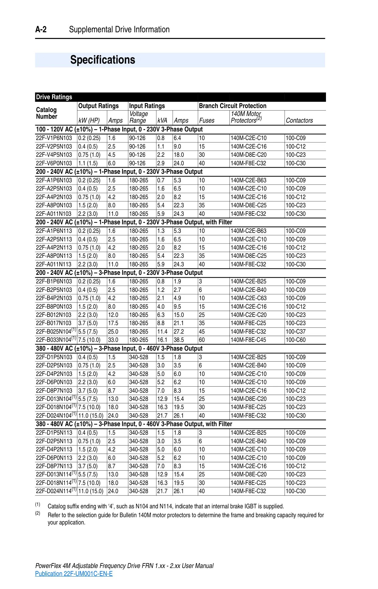
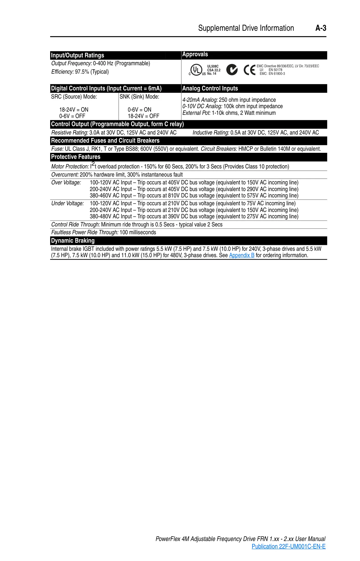
Allen-Bradley Powerflex 4M Specifications
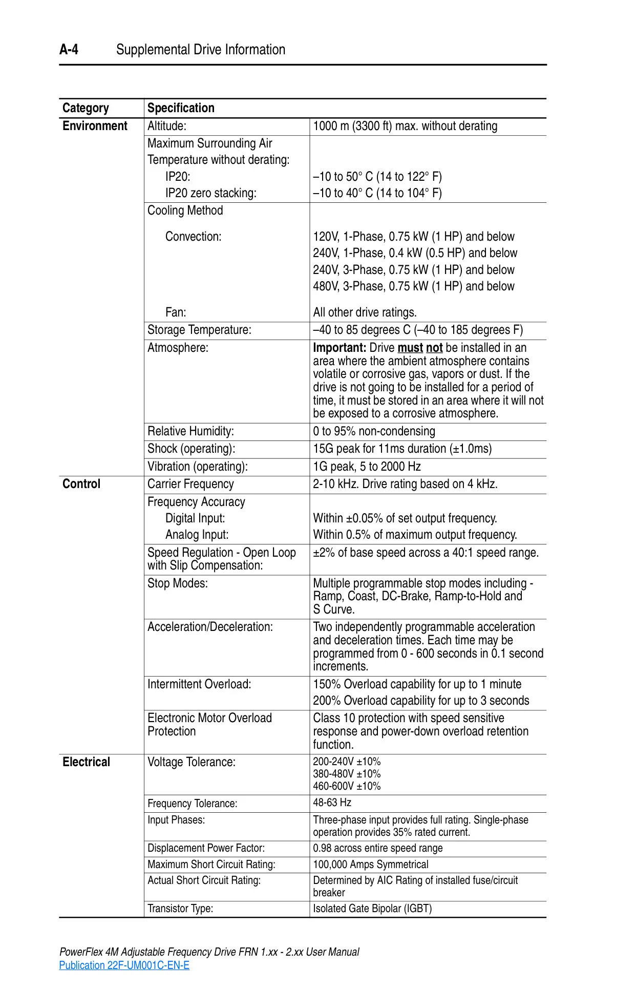
| Feature | Specification |
|---|---|
| Output Frequency Range | 0-400 Hz (Programmable) |
| Efficiency | 97.5% (Typical) |
| Input Voltage Tolerance | ±10% of rated voltage (e.g., 200-240V AC, 380-480V AC) |
| Input Frequency Tolerance | 48-63 Hz |
| Input Phases | Three-phase input provides full rating. Single-phase operation provides 35% rated current. |
| Displacement Power Factor | 0.98 across entire speed range |
| Maximum Short Circuit Rating | 100,000 Amps Symmetrical (Determined by AIC Rating of installed fuse/circuit breaker) |
| Transistor Type | Isolated Gate Bipolar (IGBT) |
| Motor Protection | I²t overload protection - 150% for 60 seconds, 200% for 3 seconds (Provides Class 10 protection) |
| Overcurrent Protection | 200% hardware limit, 300% instantaneous fault |
| Over Voltage Trip (200-240V AC Input) | 405V DC bus voltage (equivalent to 290V AC incoming line) |
| Under Voltage Trip (200-240V AC Input) | 210V DC bus voltage (equivalent to 150V AC incoming line) |
| Control Ride Through | Minimum 0.5 seconds (typical 2 seconds) |
| Faultless Power Ride Through | 100 milliseconds |
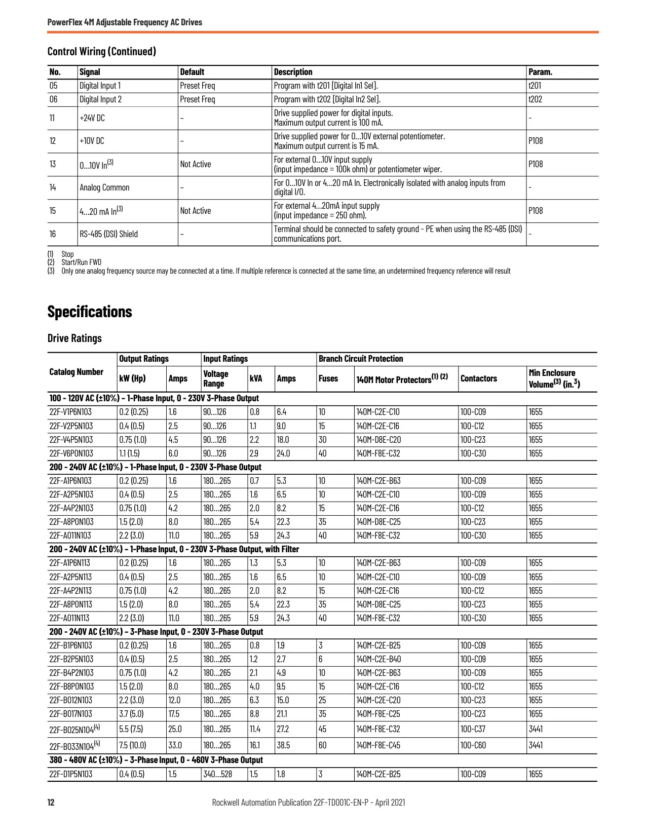
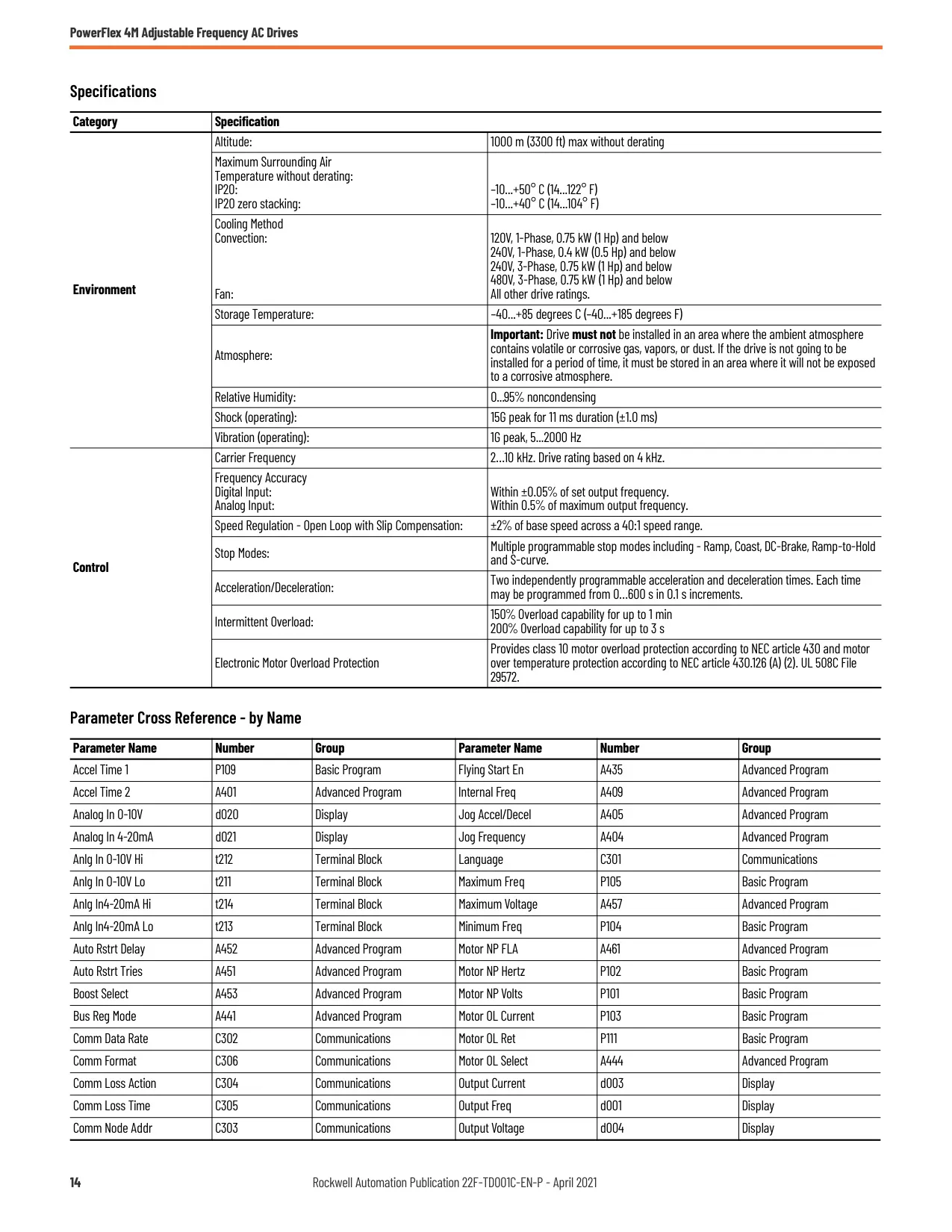
| Altitude | 1000m (3300 ft) max without derating |
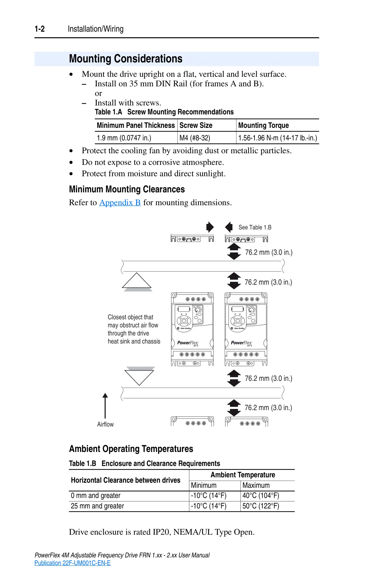
| Maximum Surrounding Air Temperature (IP20) | -10 to 50°C (14 to 122°F) |
| Storage Temperature | -40 to 85°C (-40 to 185°F) |
| Relative Humidity | 0 to 95% non-condensing |
| Shock (operating) | 15G peak for 11ms duration (±1.0ms) |
| Vibration (operating) | 1G peak, 5 to 2000 Hz |
| Carrier Frequency | 2-10 kHz (Drive rating based on 4 kHz) |
| Frequency Accuracy (Digital Input) | Within ±0.05% of set output frequency |
| Speed Regulation (Open Loop with Slip Comp) | ±2% of base speed across a 40:1 speed range |
| Stop Modes | Multiple programmable (Ramp, Coast, DC-Brake, Ramp-to-Hold, S Curve) |
| Acceleration/Deceleration Times | Two independently programmable (0-600 seconds in 0.1 second increments) |
| Intermittent Overload | 150% for up to 1 minute, 200% for up to 3 seconds |
Allen-Bradley Powerflex 4M Details
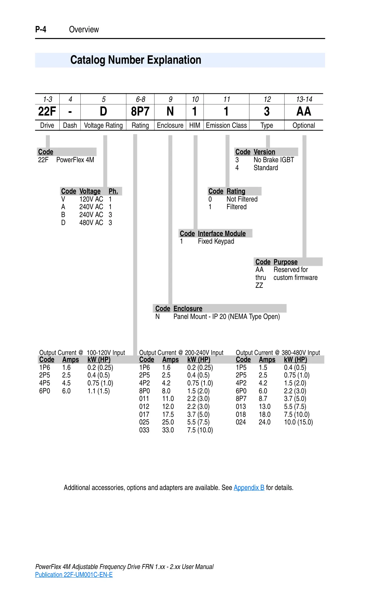
The Allen-Bradley PowerFlex 4M Adjustable Frequency AC Drive is engineered to provide essential functionality for installing, starting up, and troubleshooting industrial motor control applications. This compact drive family is designed for global availability, offering a flexible and cost-effective solution for stand-alone machine control.
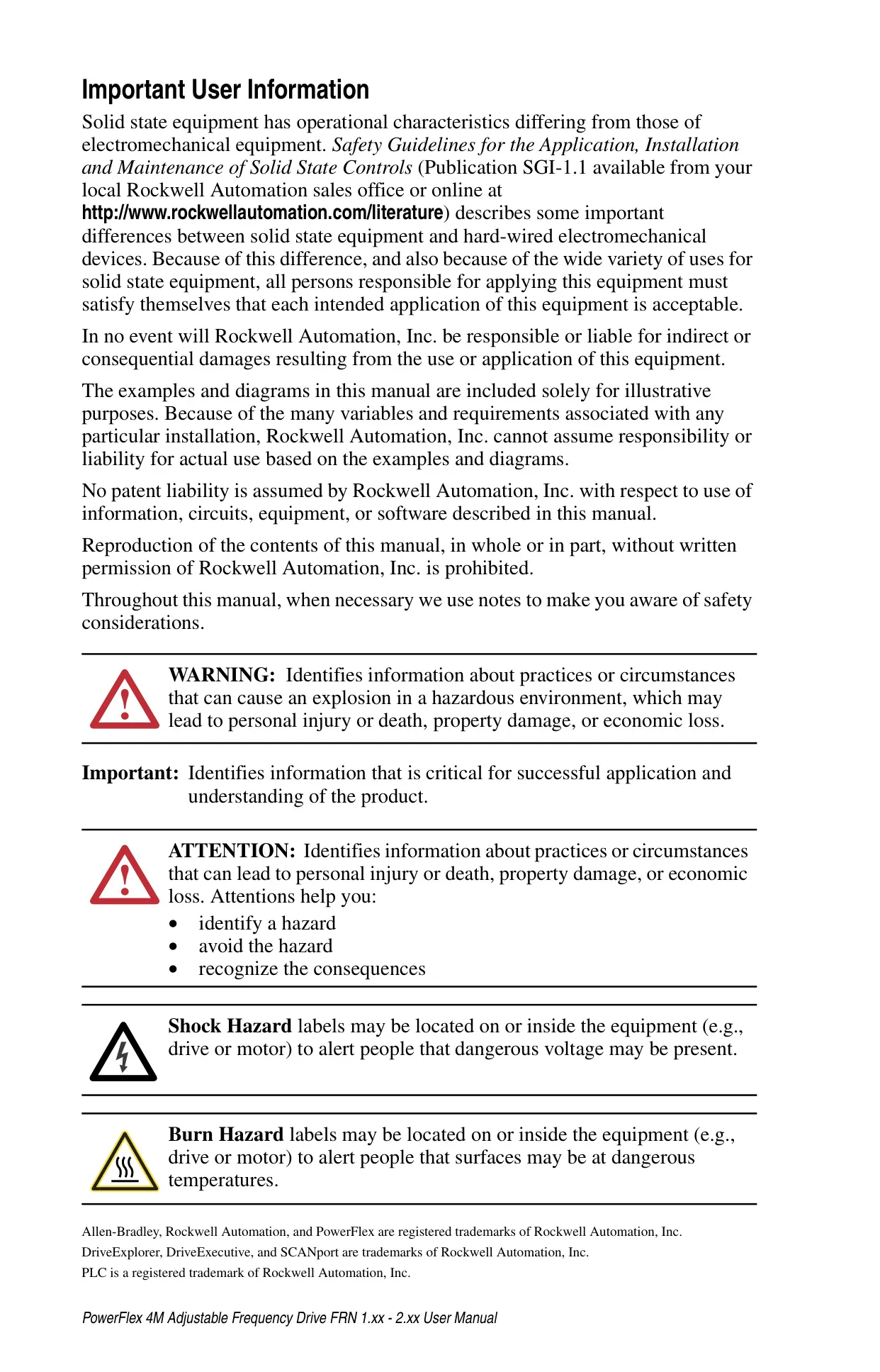
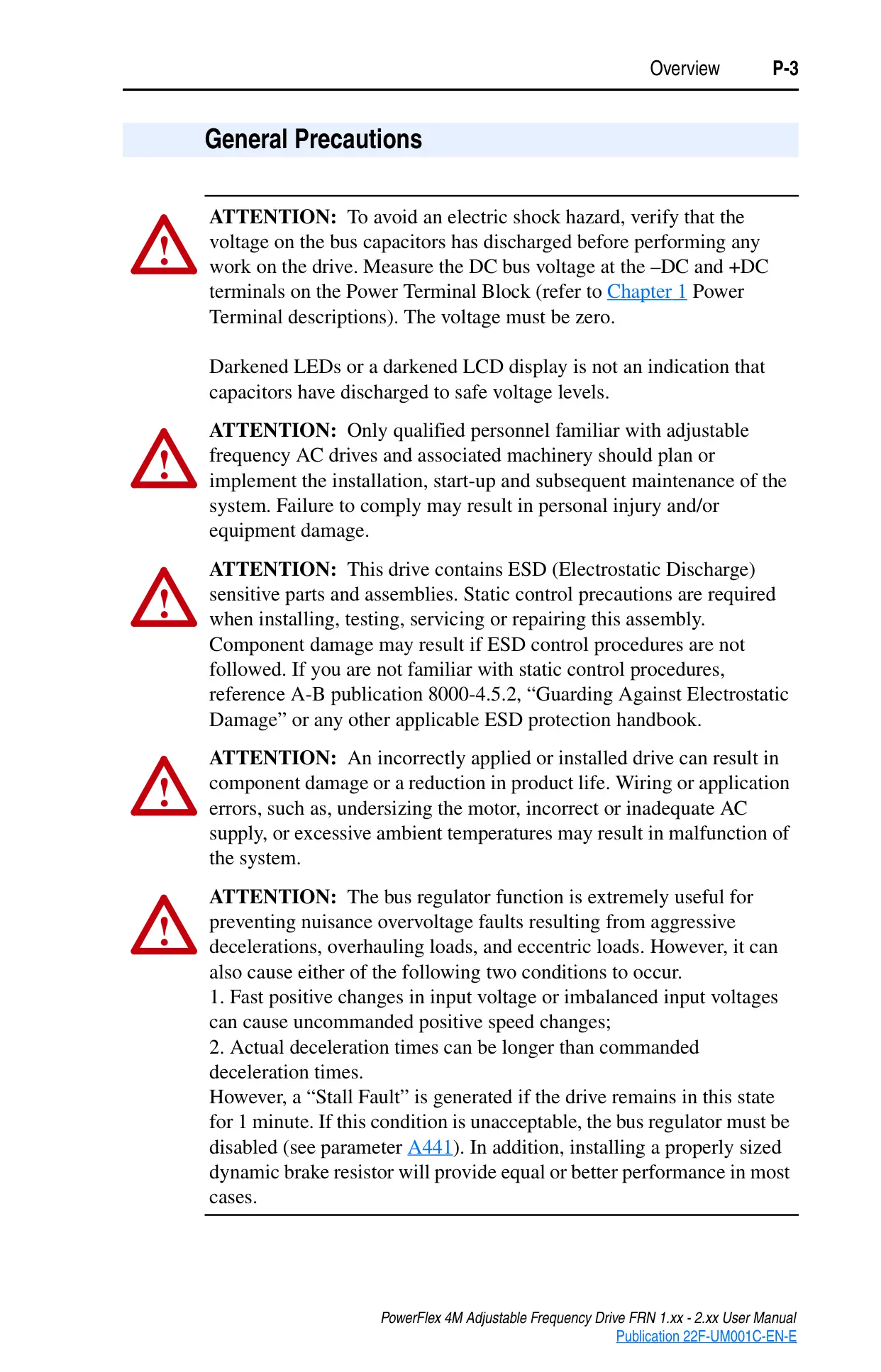
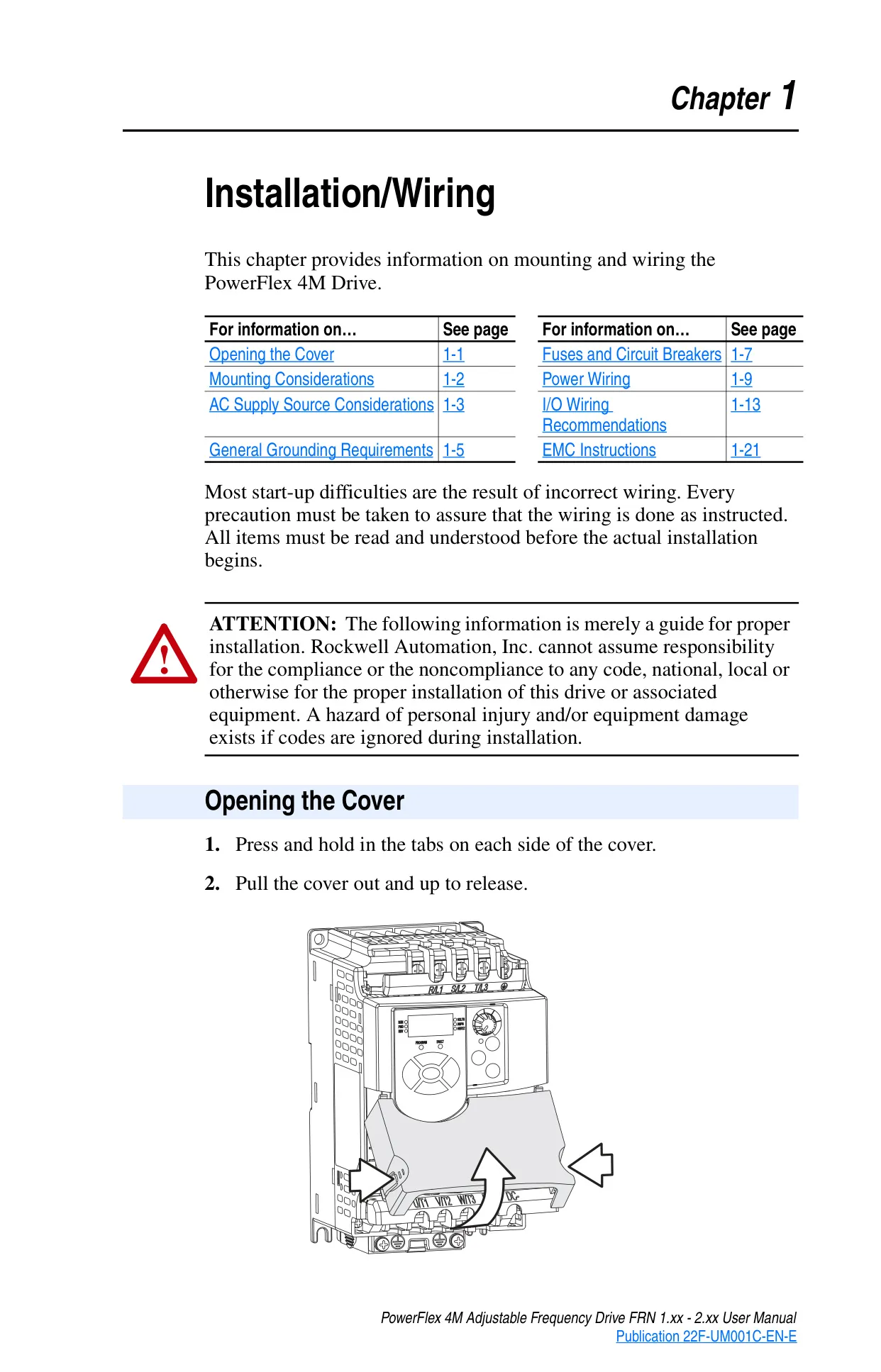
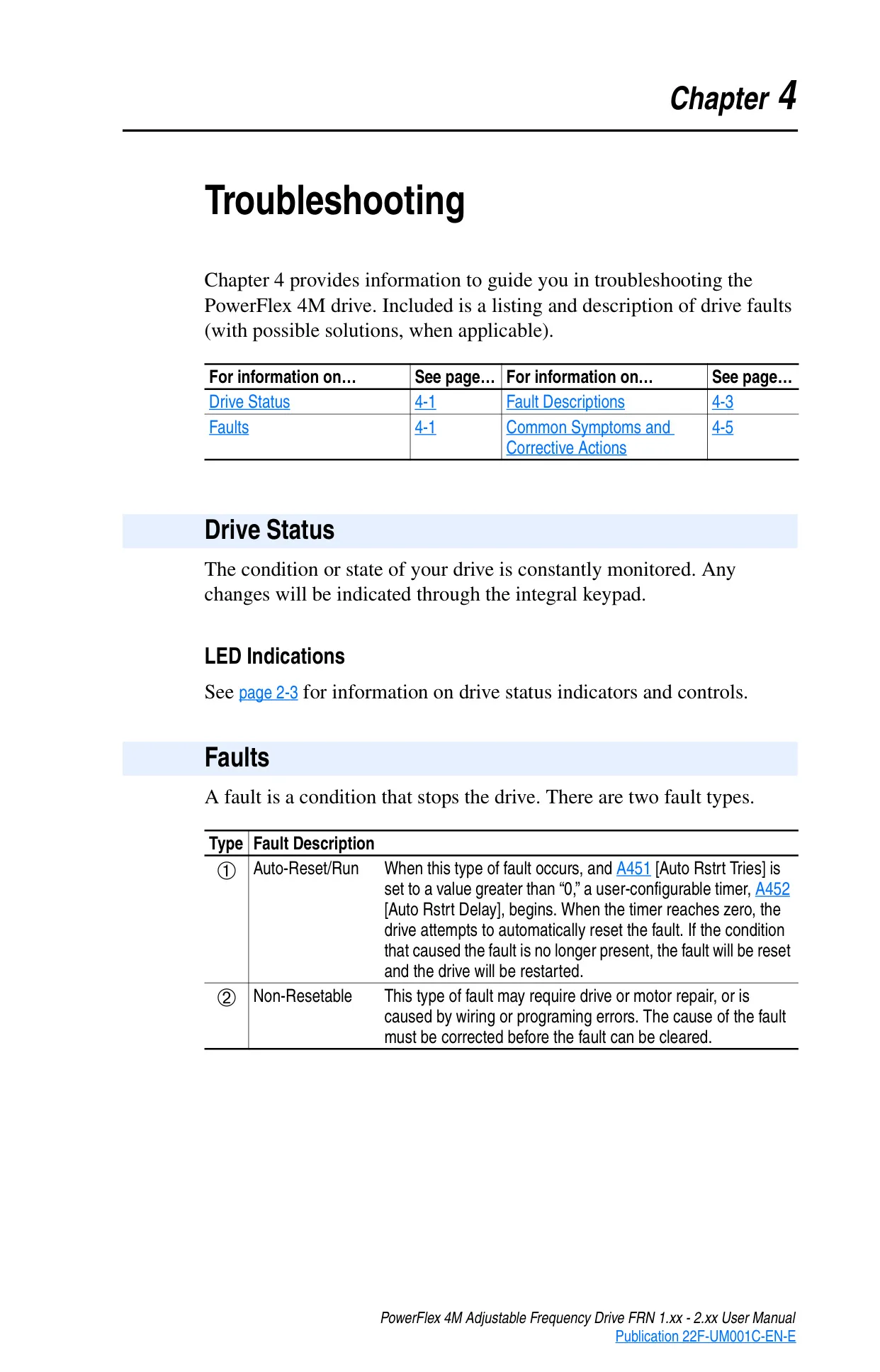
A core focus of the PowerFlex 4M is safety and reliability. The manual emphasizes the distinct operational characteristics of solid-state equipment compared to electromechanical devices, urging users to verify proper application. Critical precautions include confirming bus capacitor discharge before any work and adhering to Electrostatic Discharge (ESD) control procedures during handling.
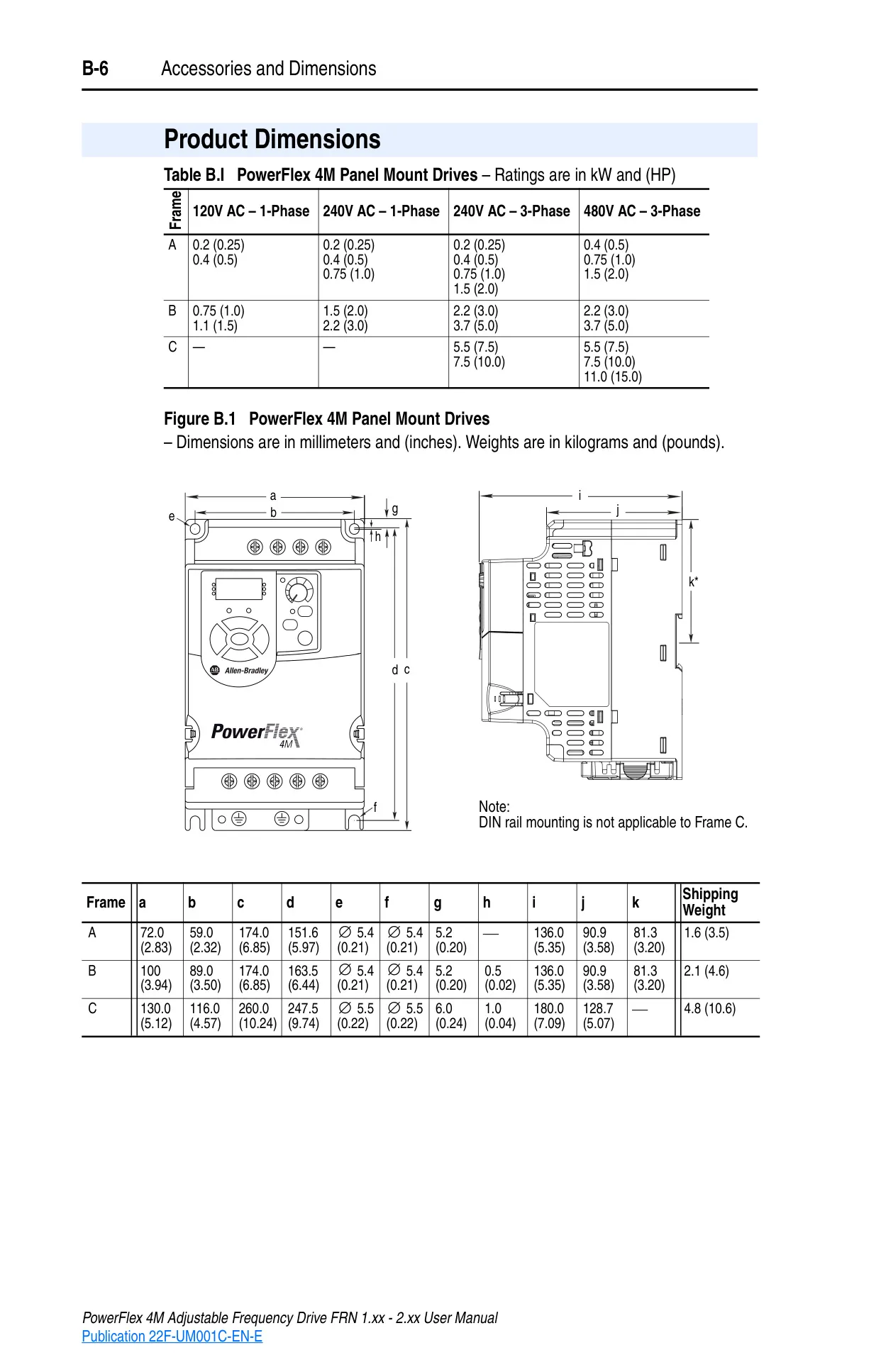
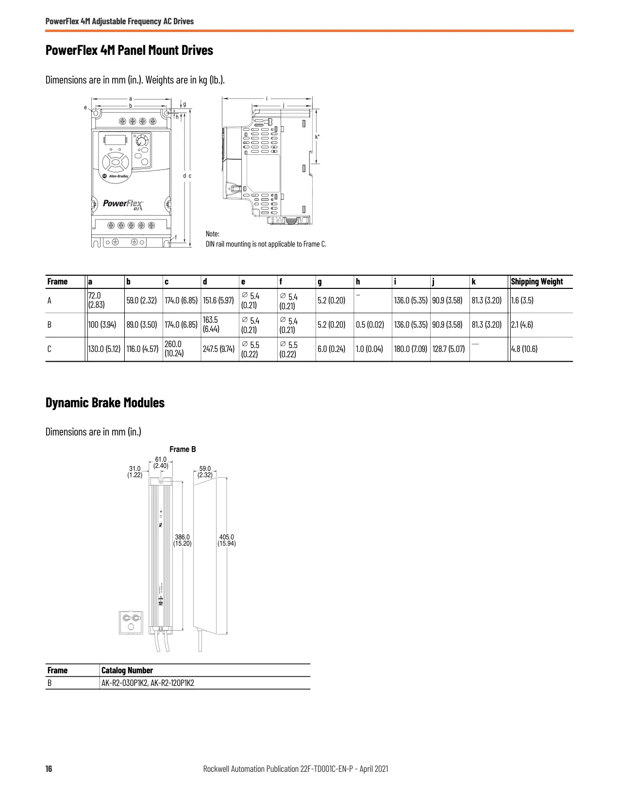
Installation is streamlined with options for mounting upright on a flat surface, either via 35mm DIN rail (for smaller frames) or screws. Adequate mounting clearances and protection from dust, metallic particles, moisture, and corrosive atmospheres are vital to ensure optimal cooling and extend product life. The drive also supports a wide ambient operating temperature range.
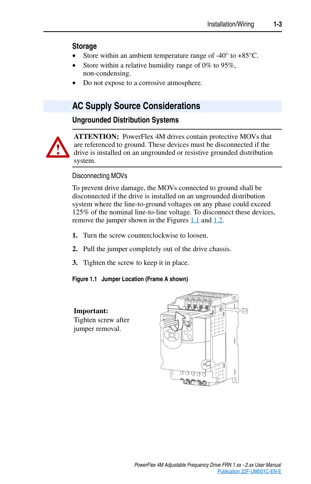
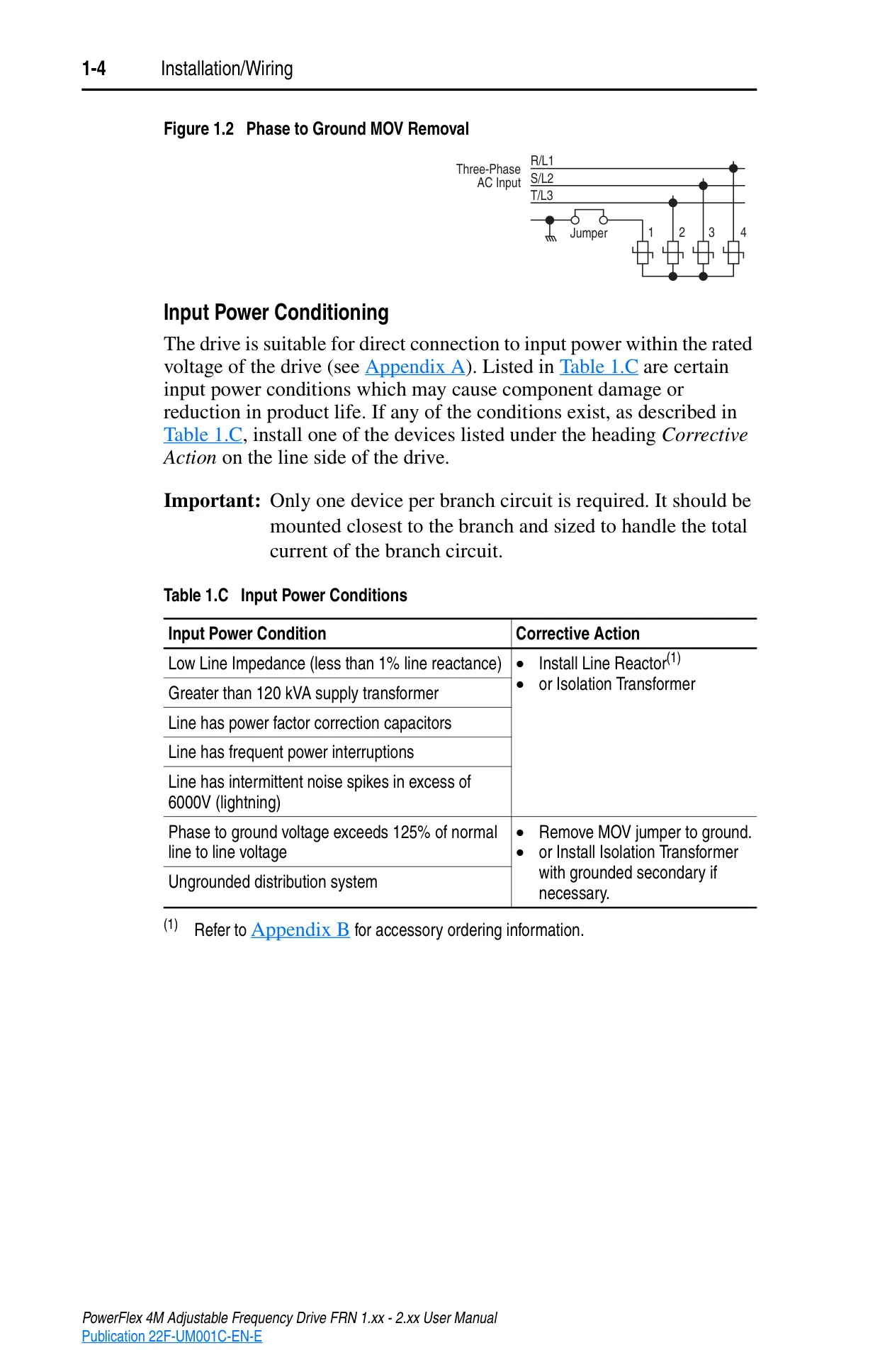
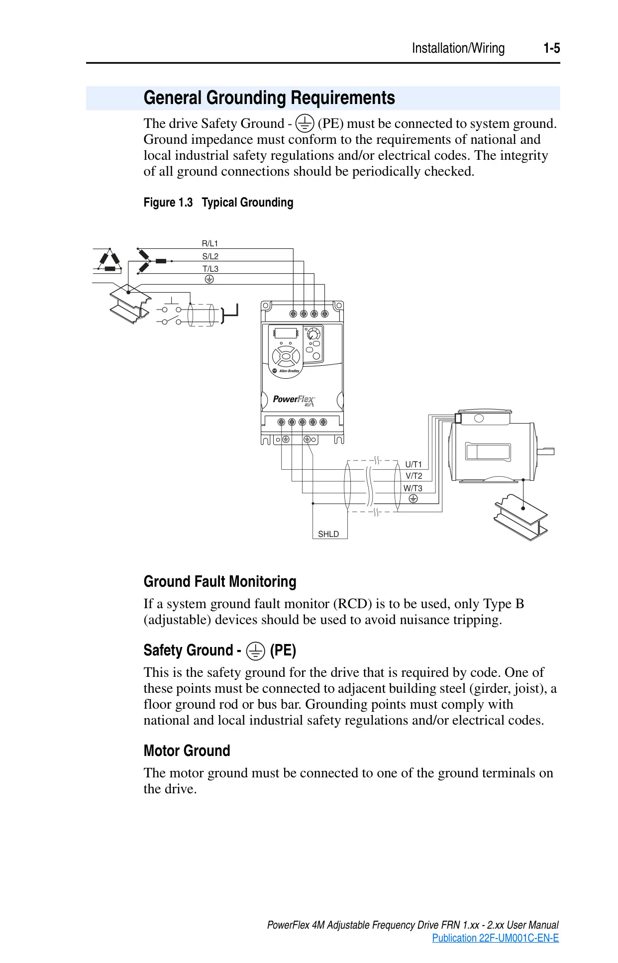
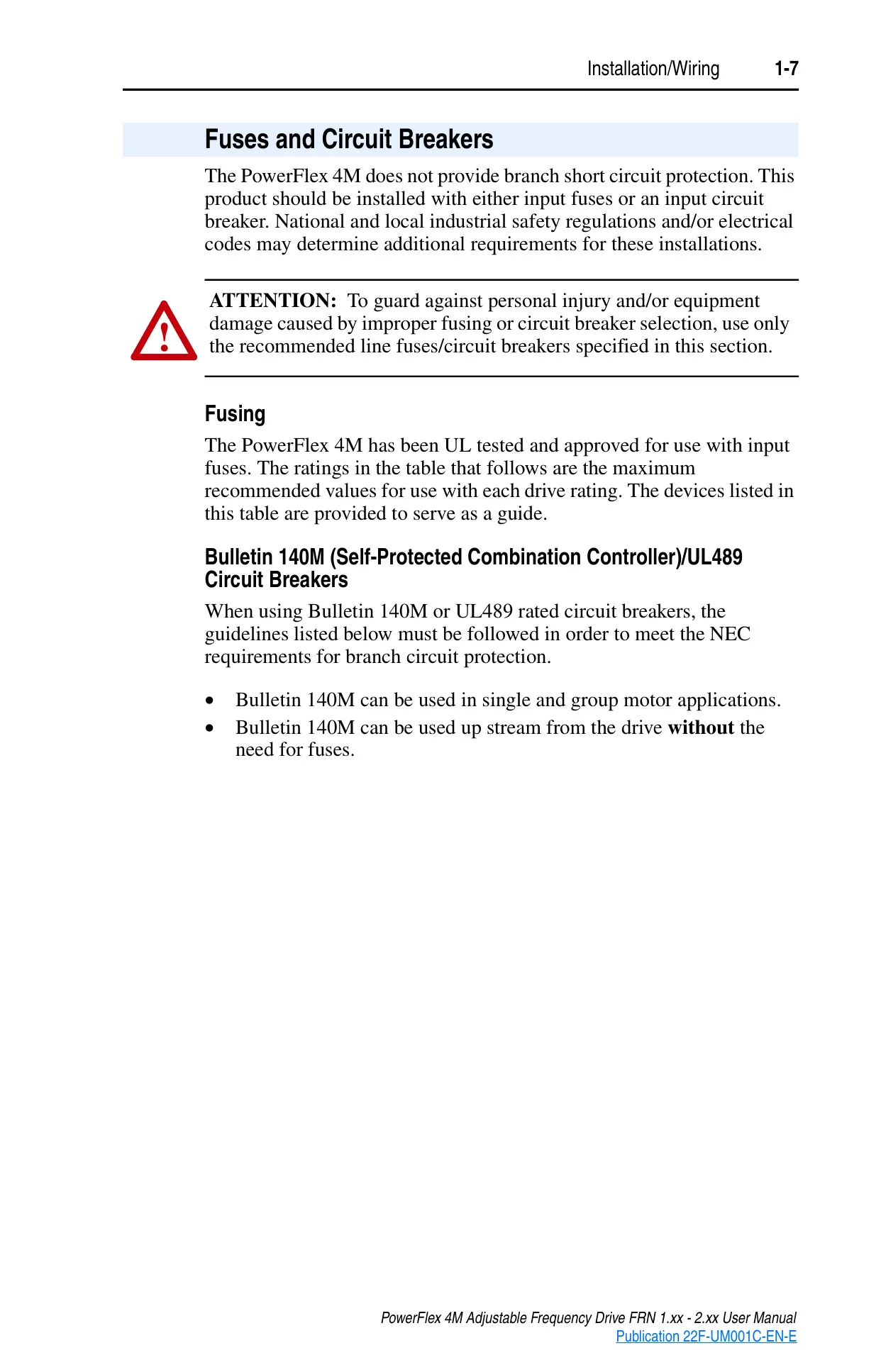
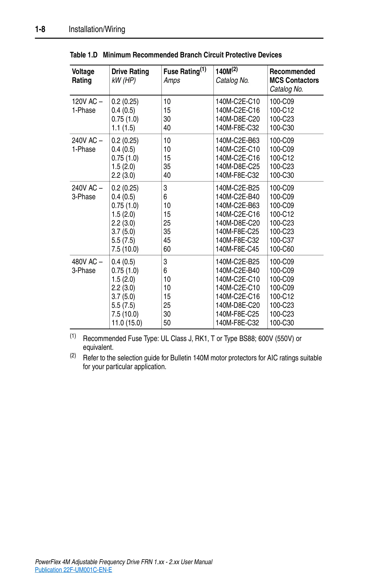
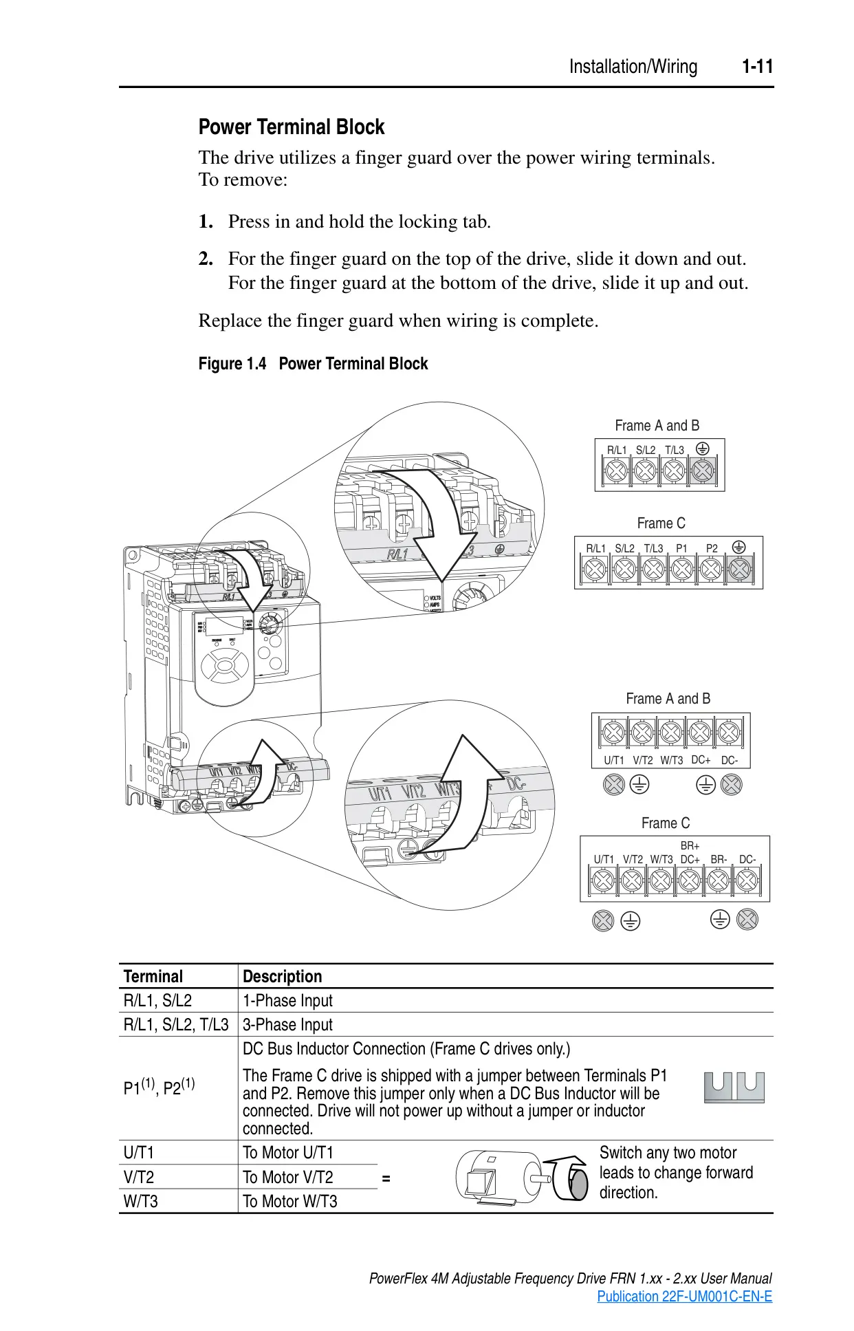
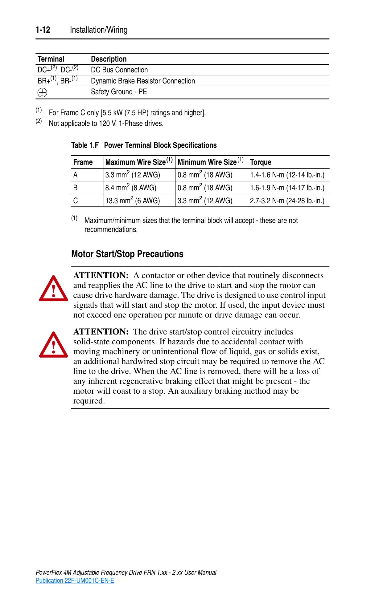
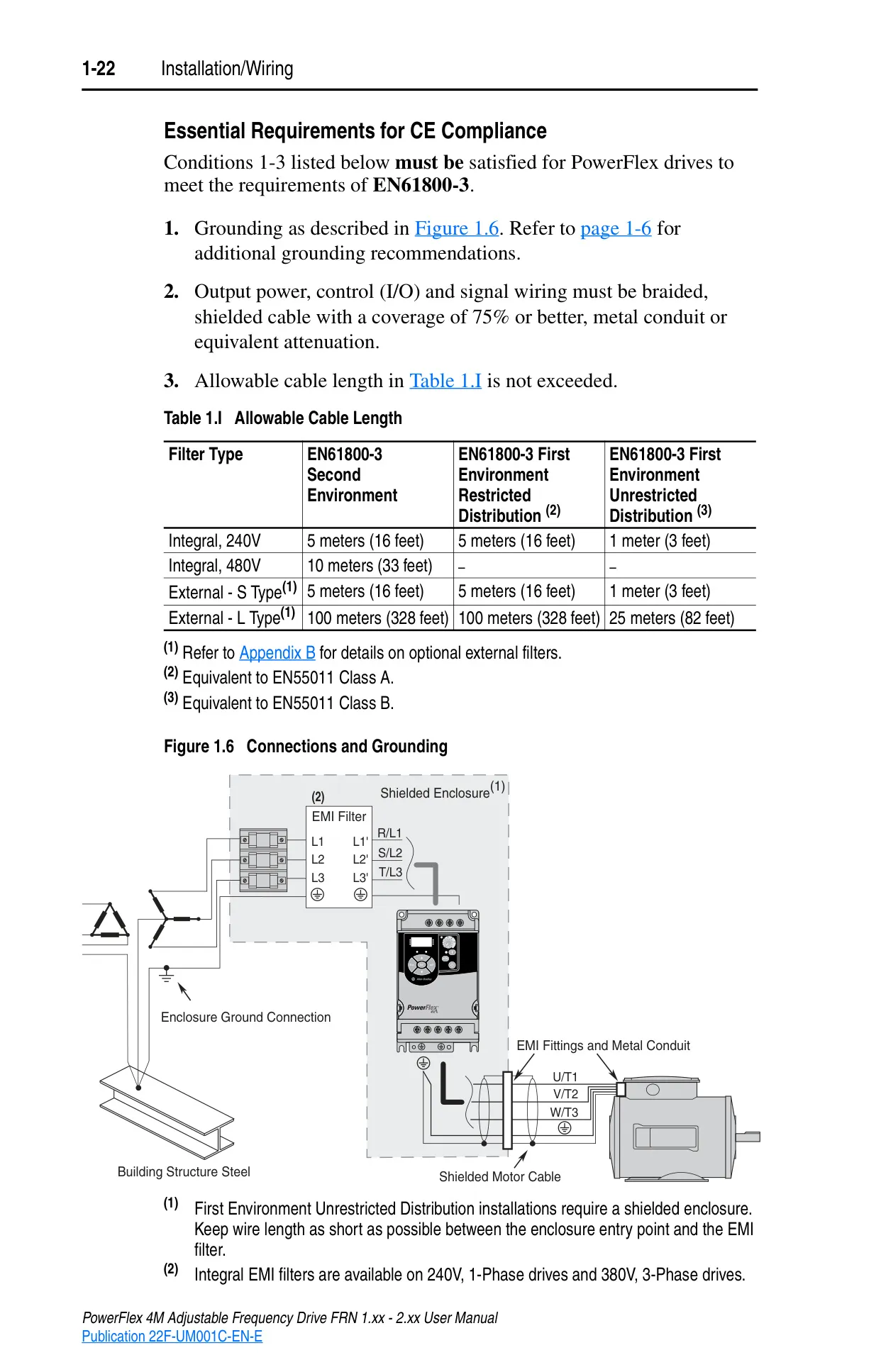
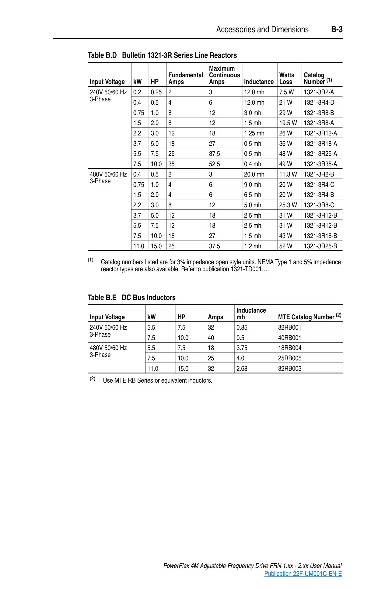
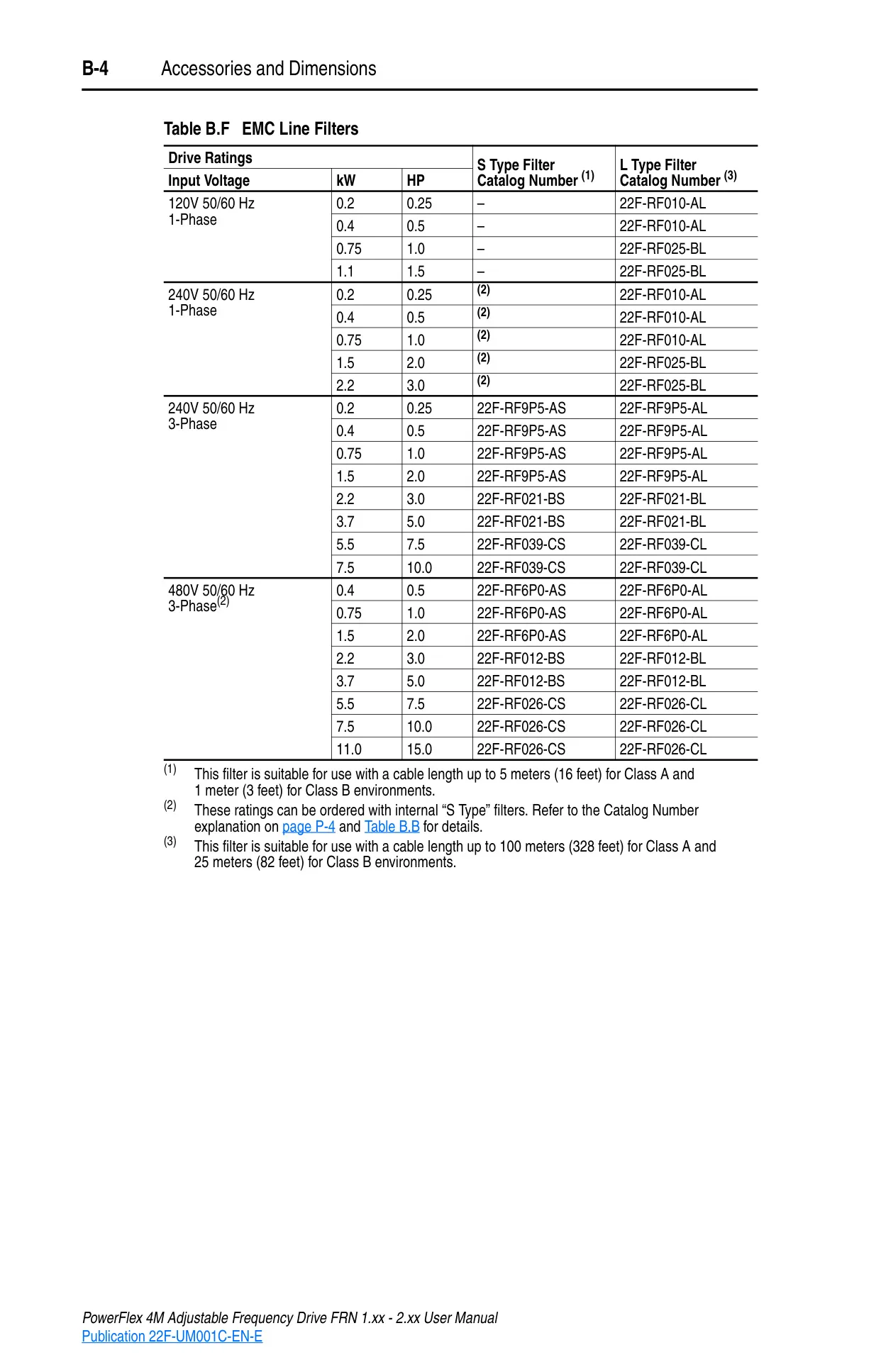
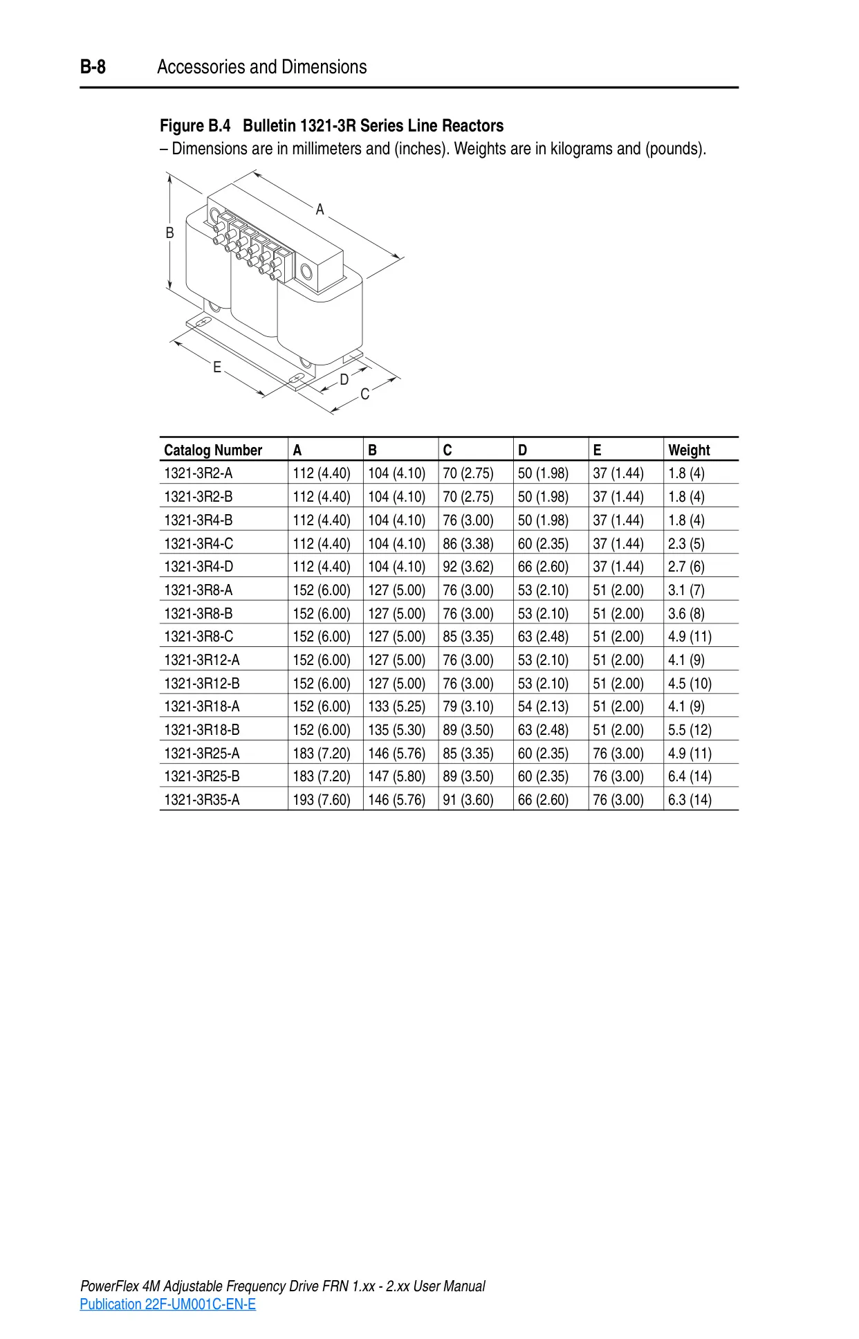
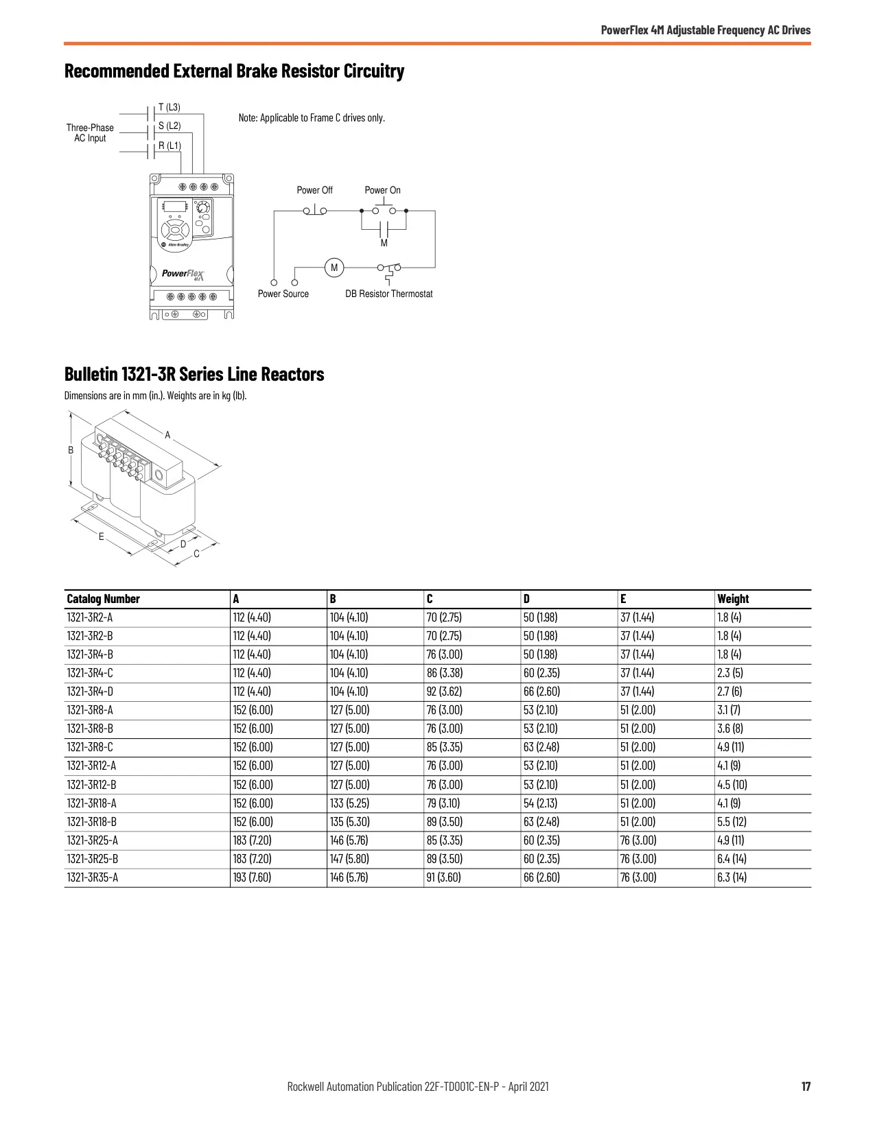
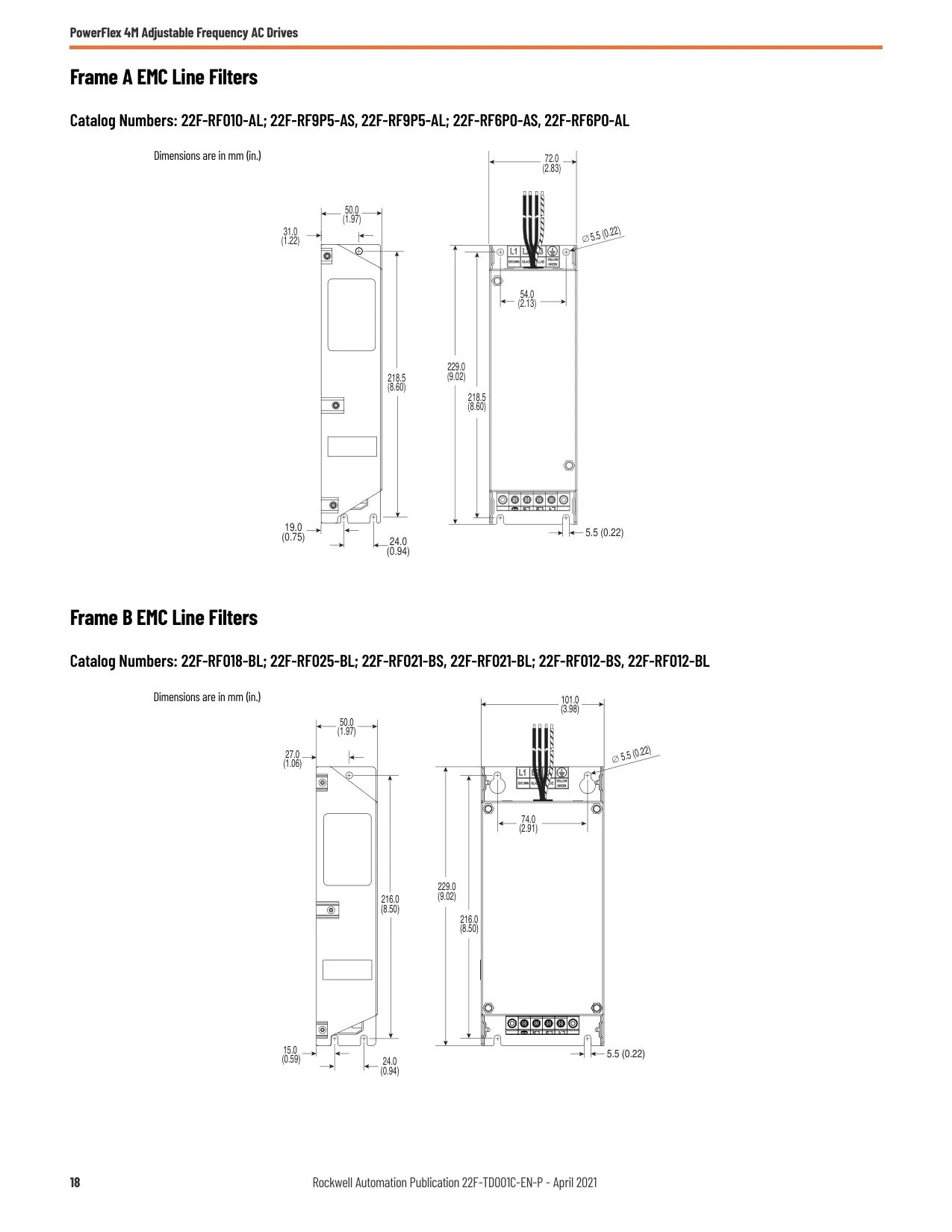
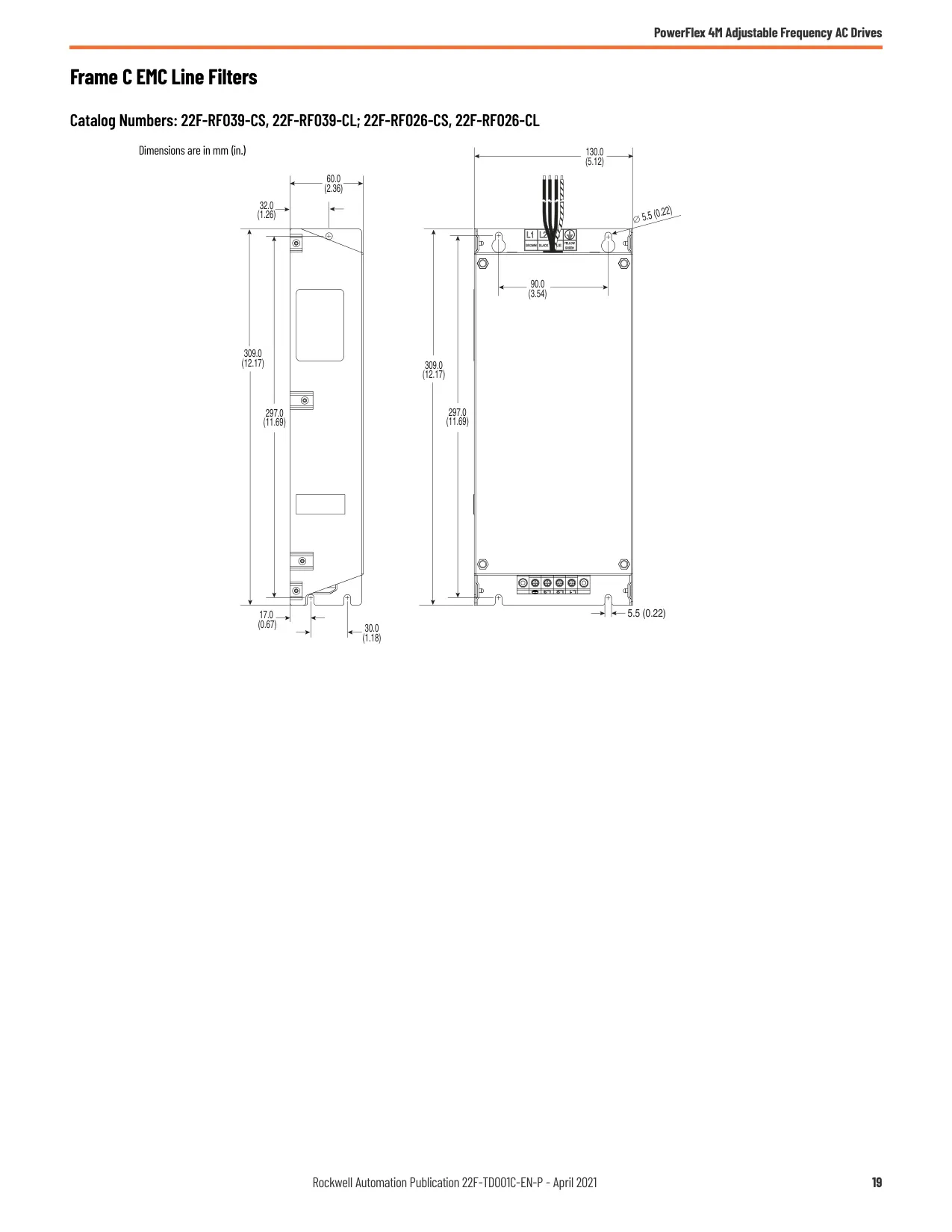
Power wiring considerations are comprehensive, covering AC supply sources, general grounding requirements, and the necessity for input fuses or circuit breakers for branch short-circuit protection. For ungrounded distribution systems, integral MOVs (Metal Oxide Varistors) must be disconnected to prevent drive damage. Input power conditioning may involve line reactors or isolation transformers.
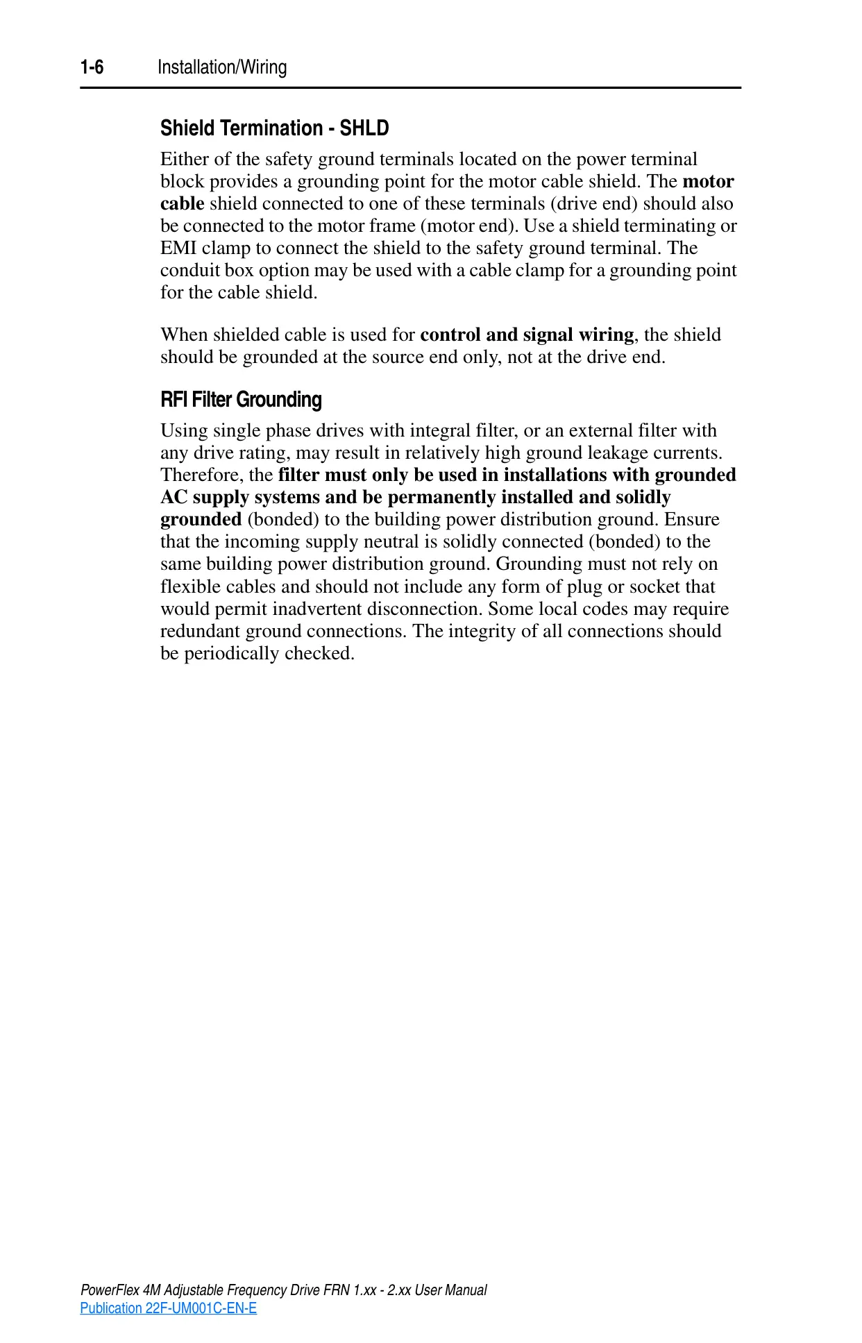
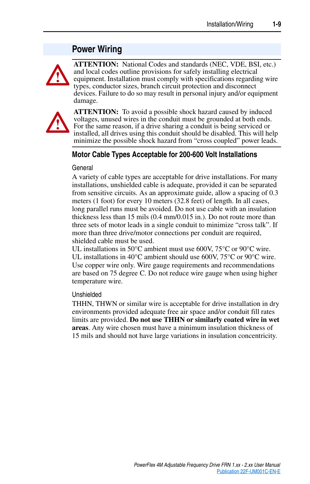
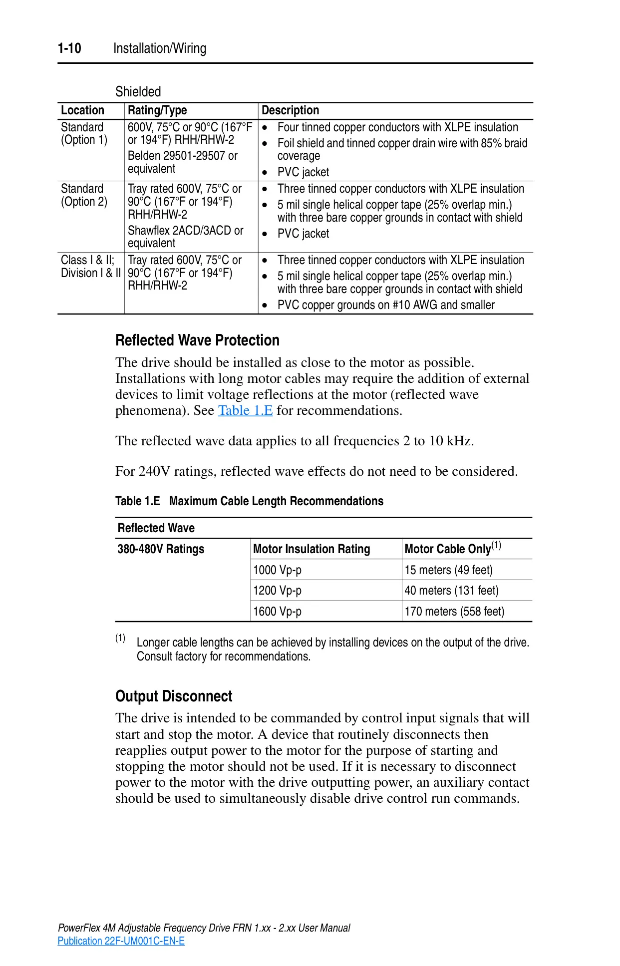
Motor connections require specific cable types; unshielded cable is acceptable for many installations with adequate separation from sensitive circuits, but shielded cable is recommended for longer runs or multiple motor leads in a single conduit. For 380-480V installations, reflected wave protection devices may be necessary for very long motor cables to prevent motor damage.
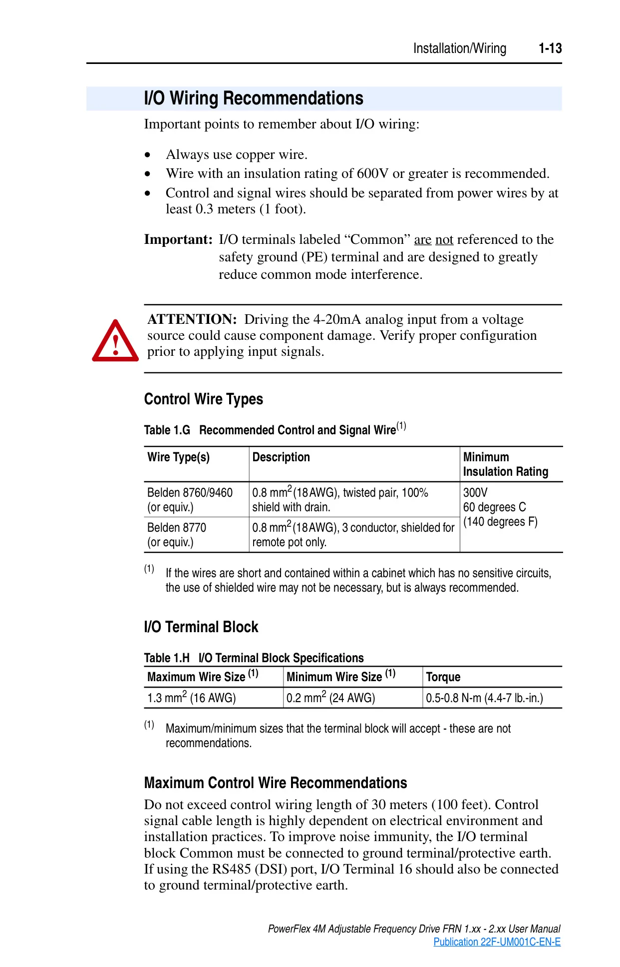
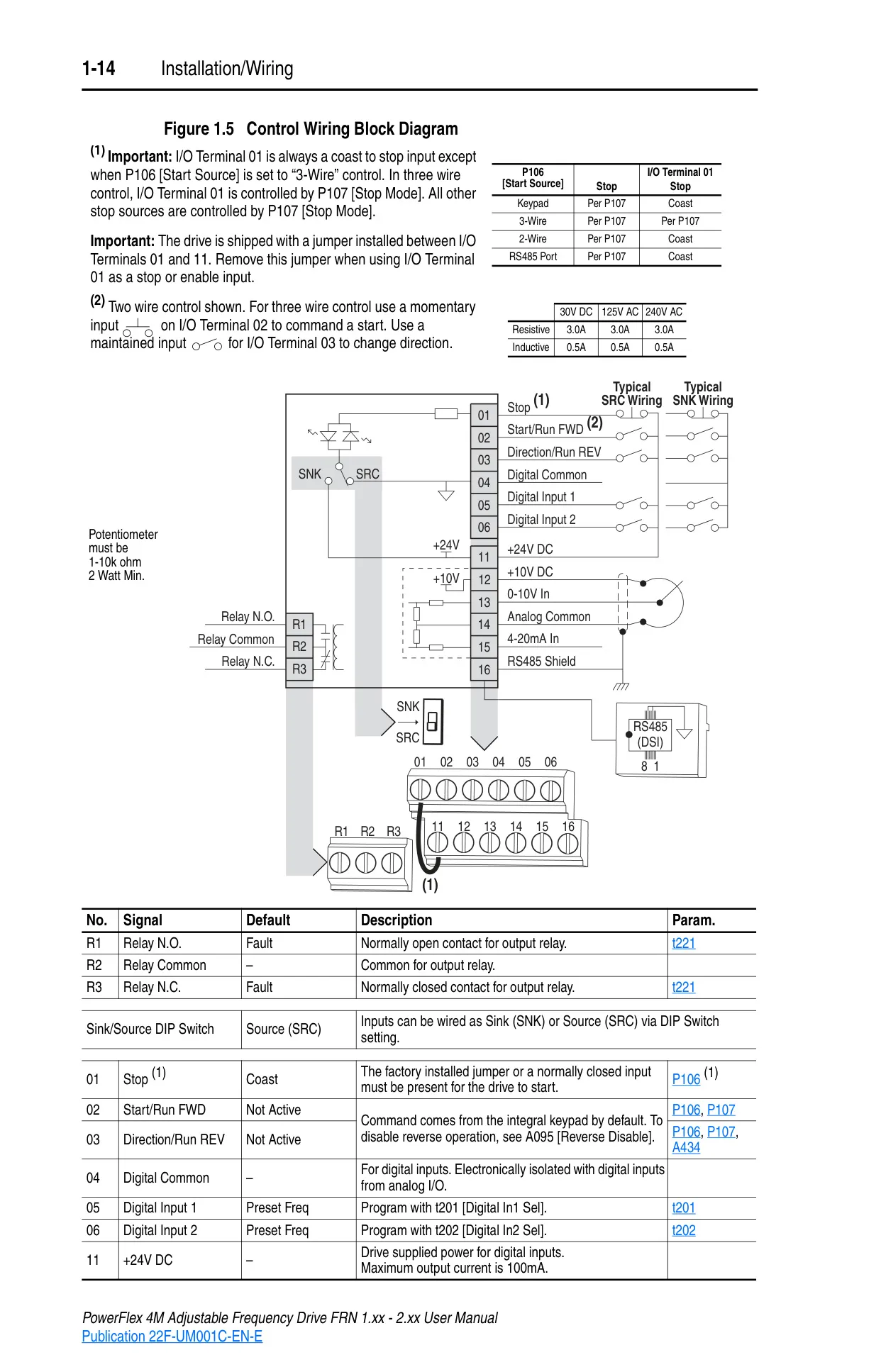
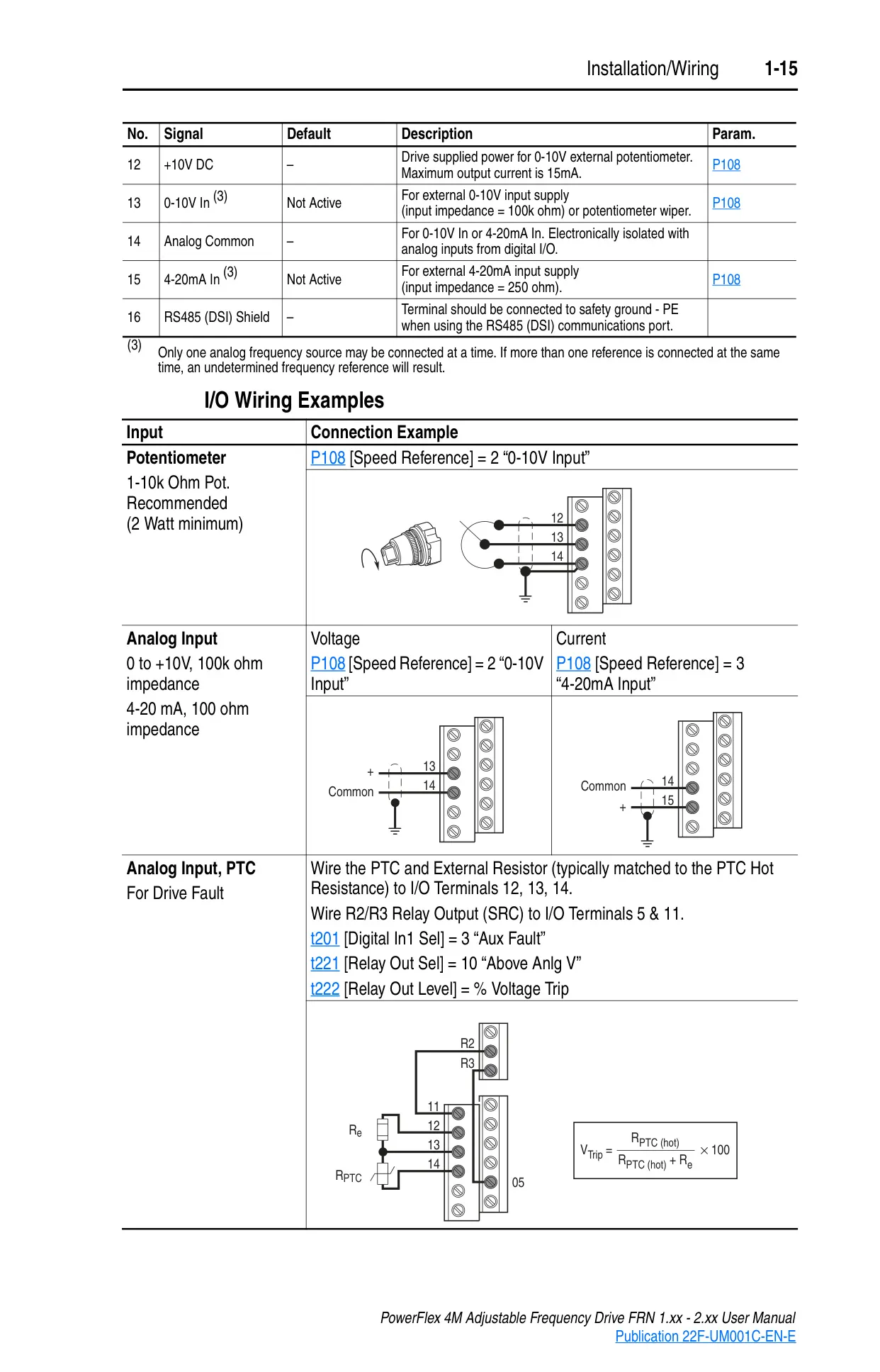
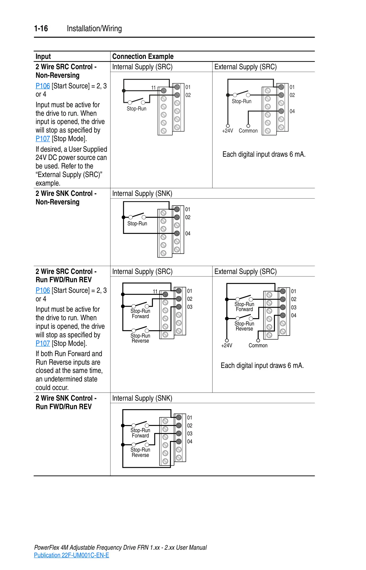
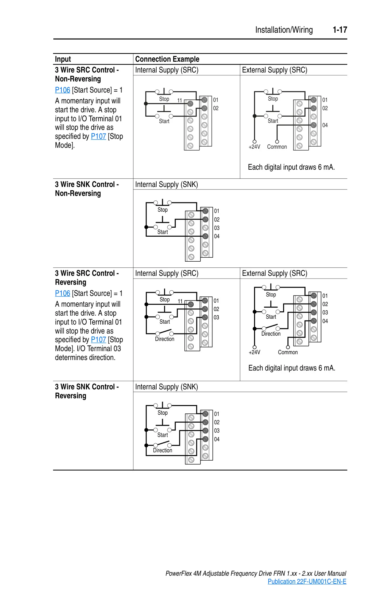
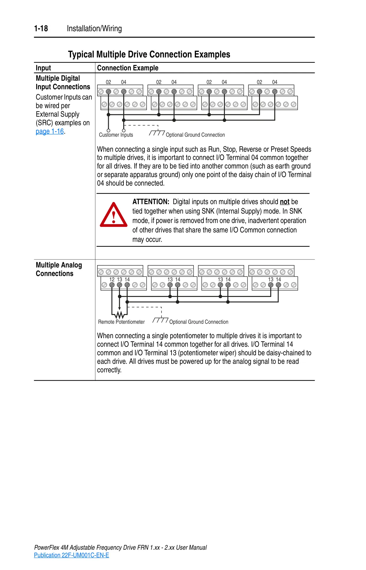
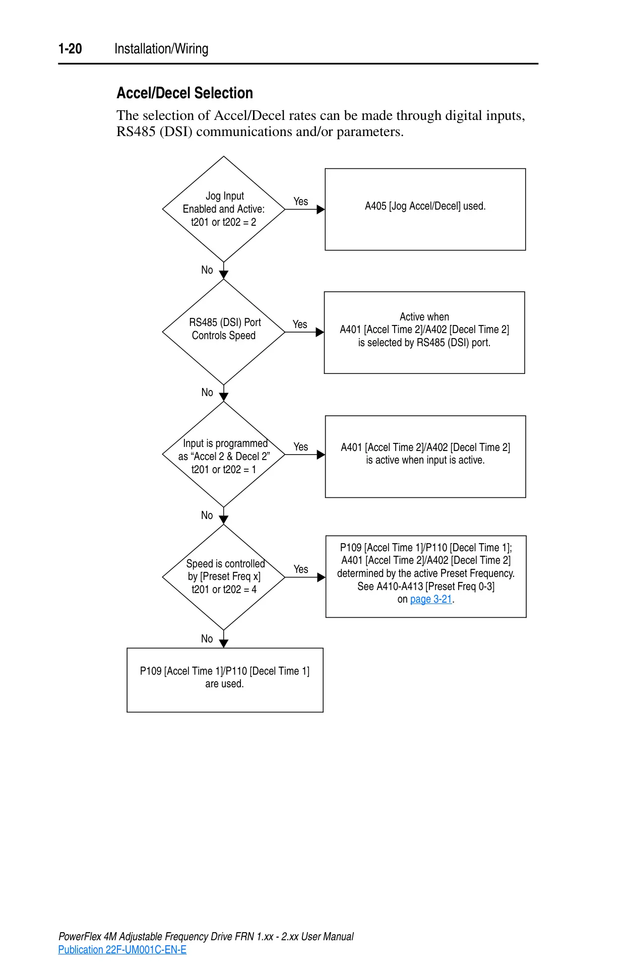
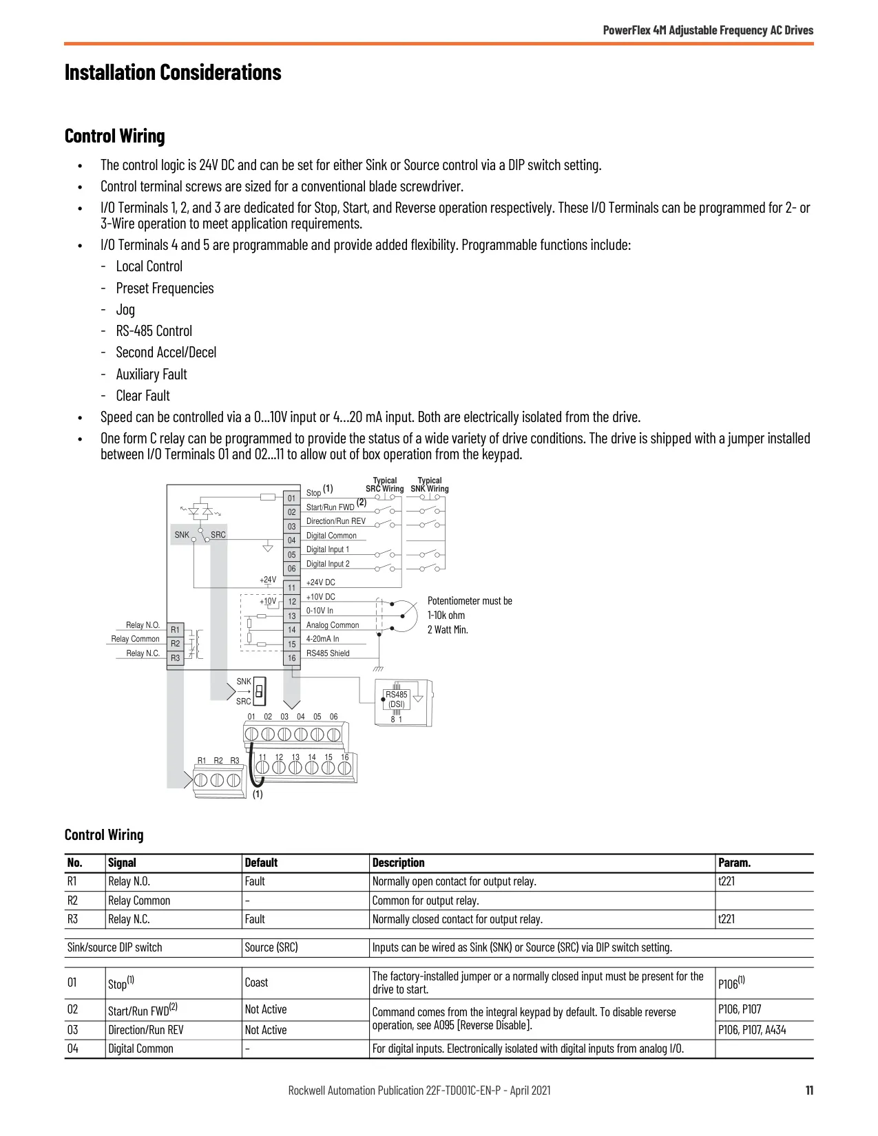
Control and I/O wiring is robust, recommending copper wire with 600V insulation. Control and signal wires should be separated from power wires to minimize interference. The drive supports various input schemes, including 2-wire and 3-wire control, and offers digital and analog input/output functionalities, with clear guidelines for maximum control wire lengths and common grounding.
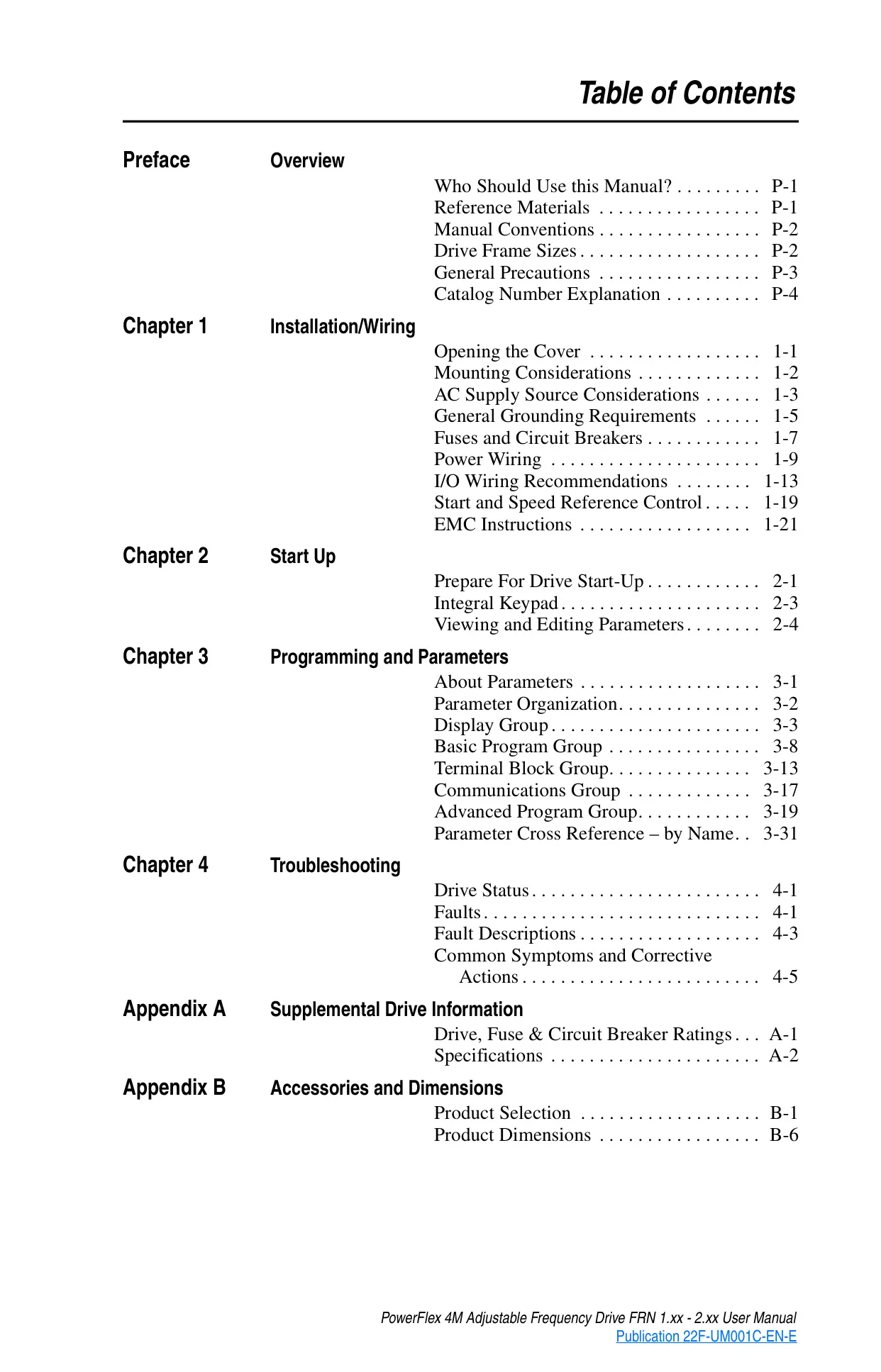
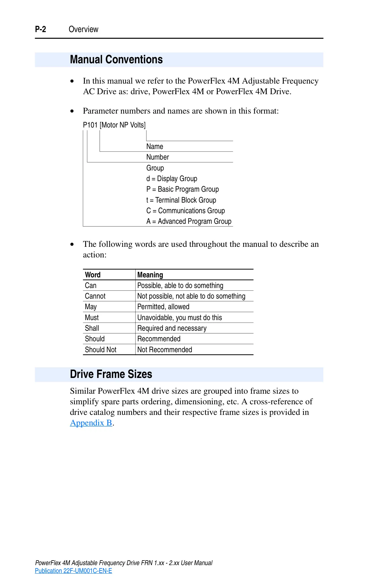
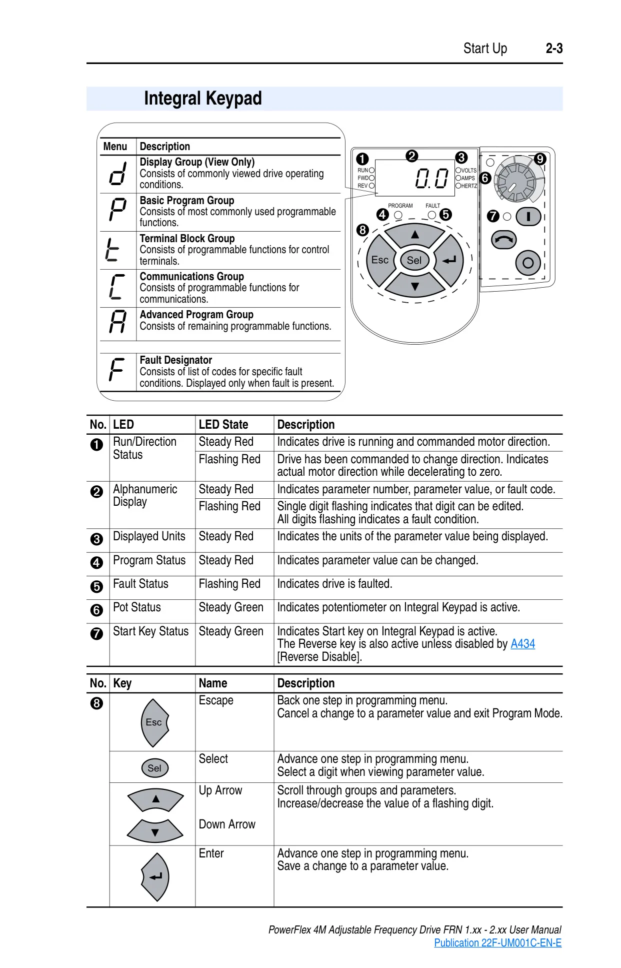
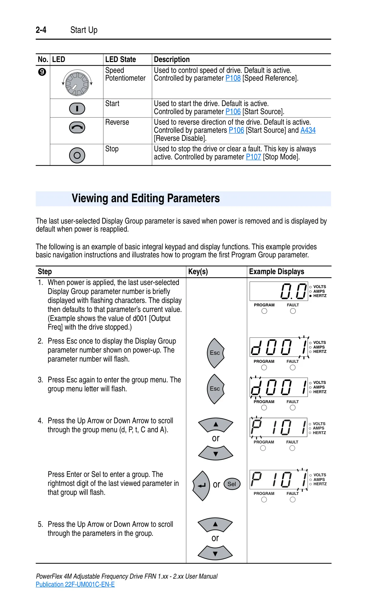
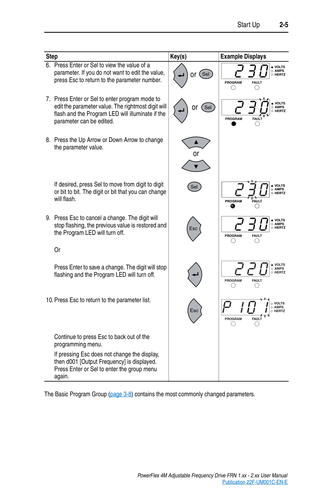
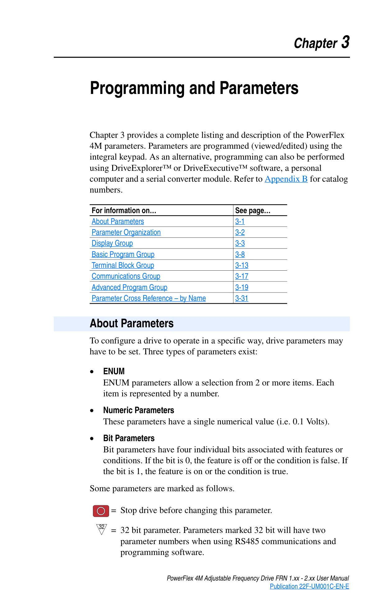
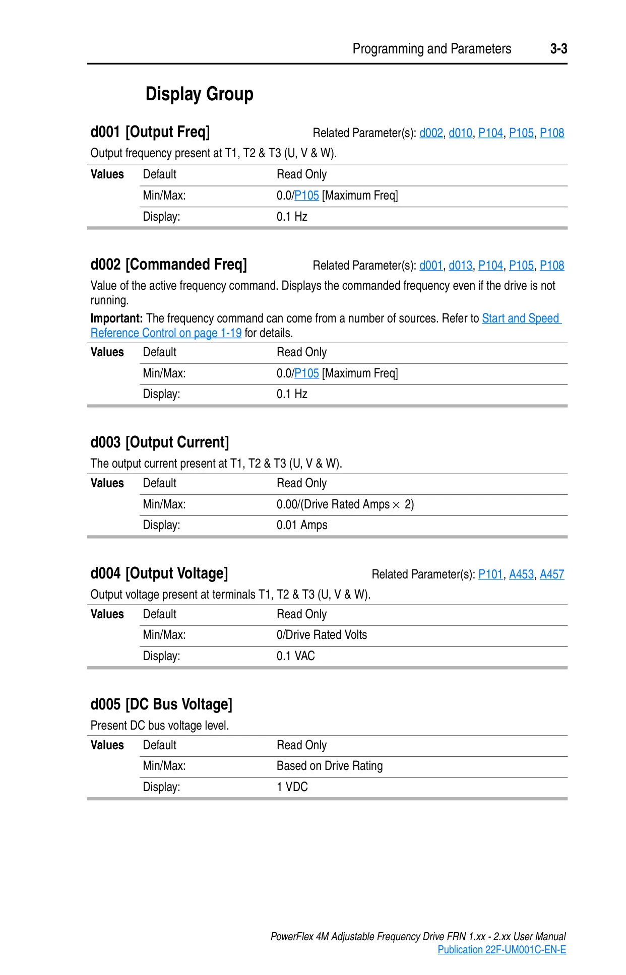
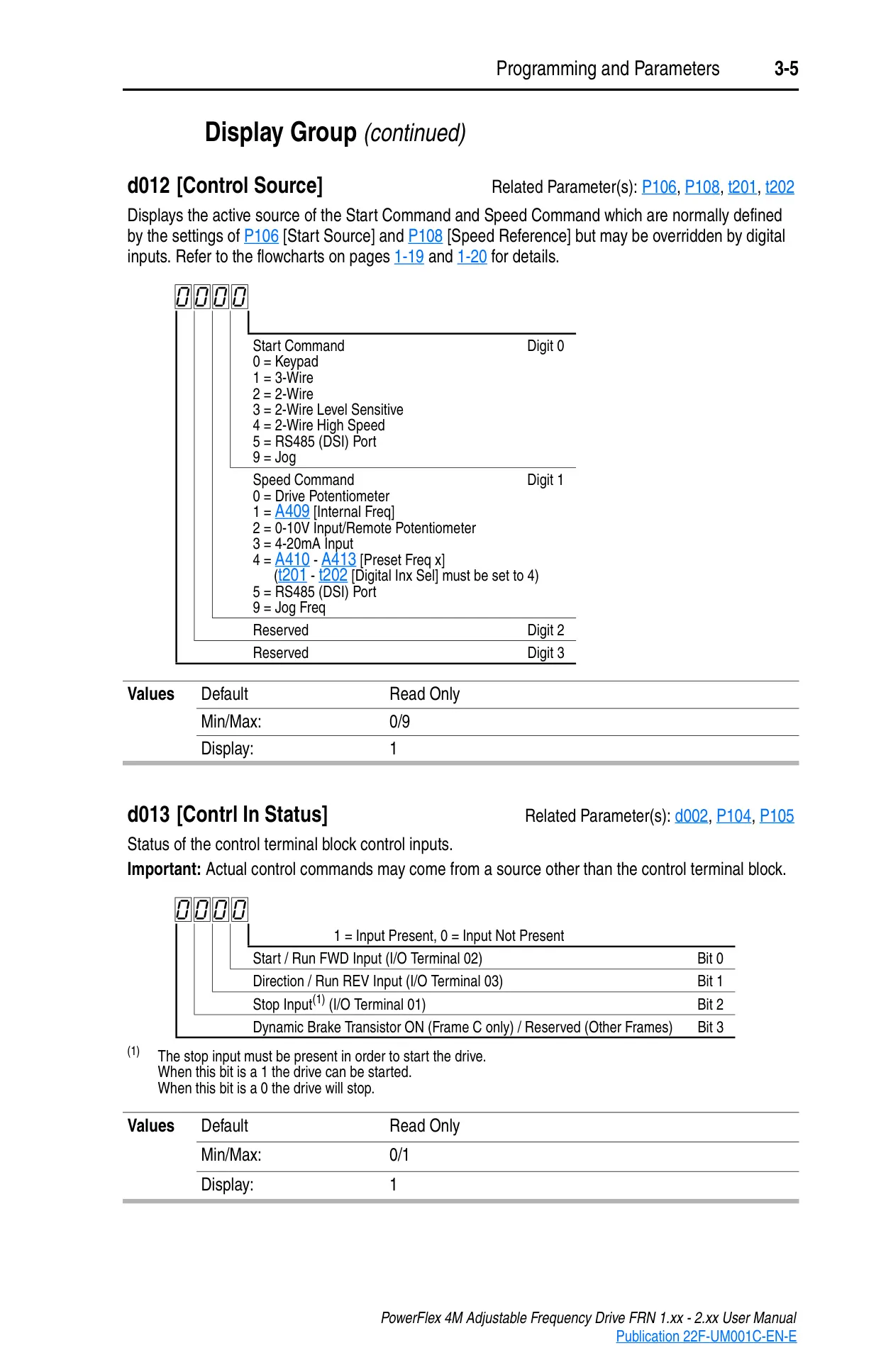
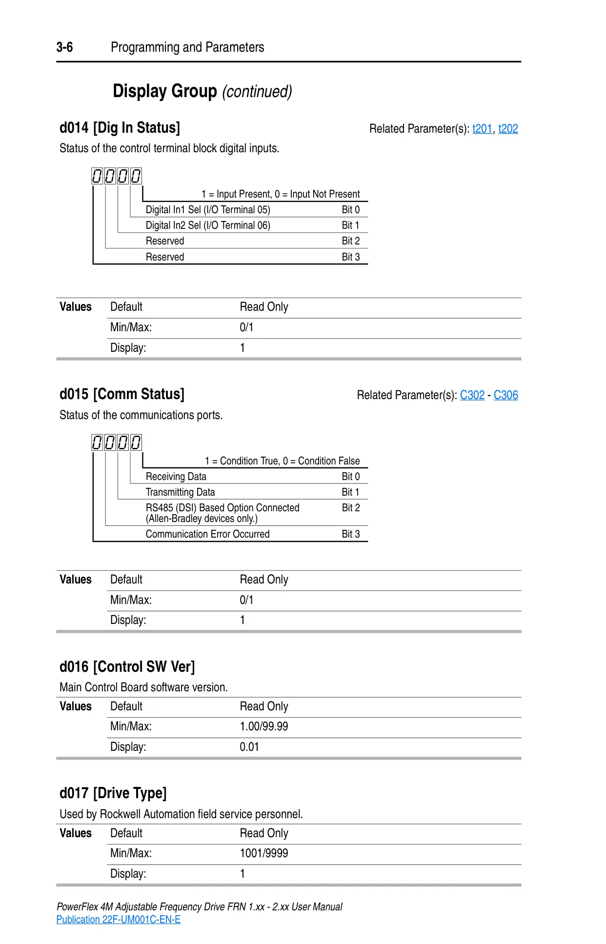
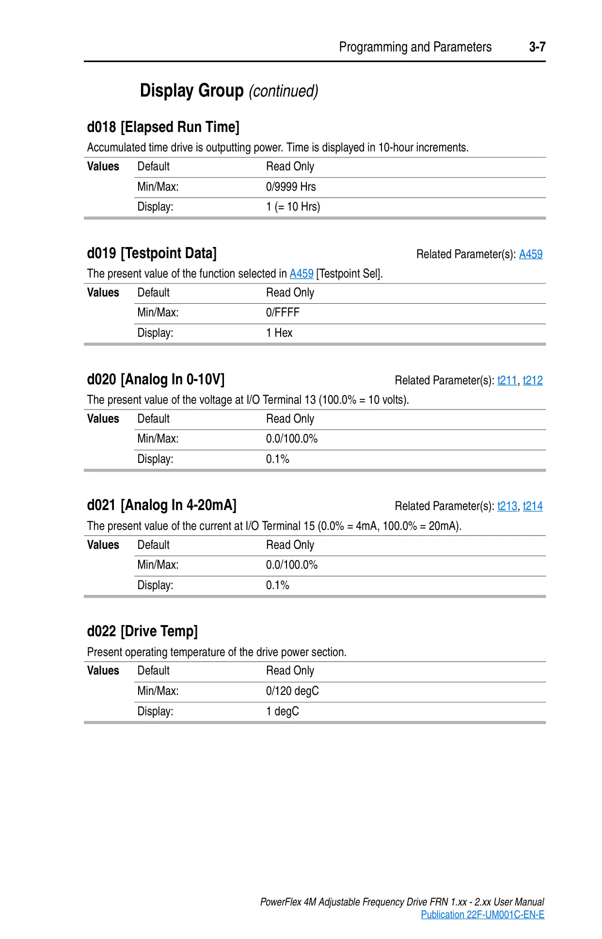
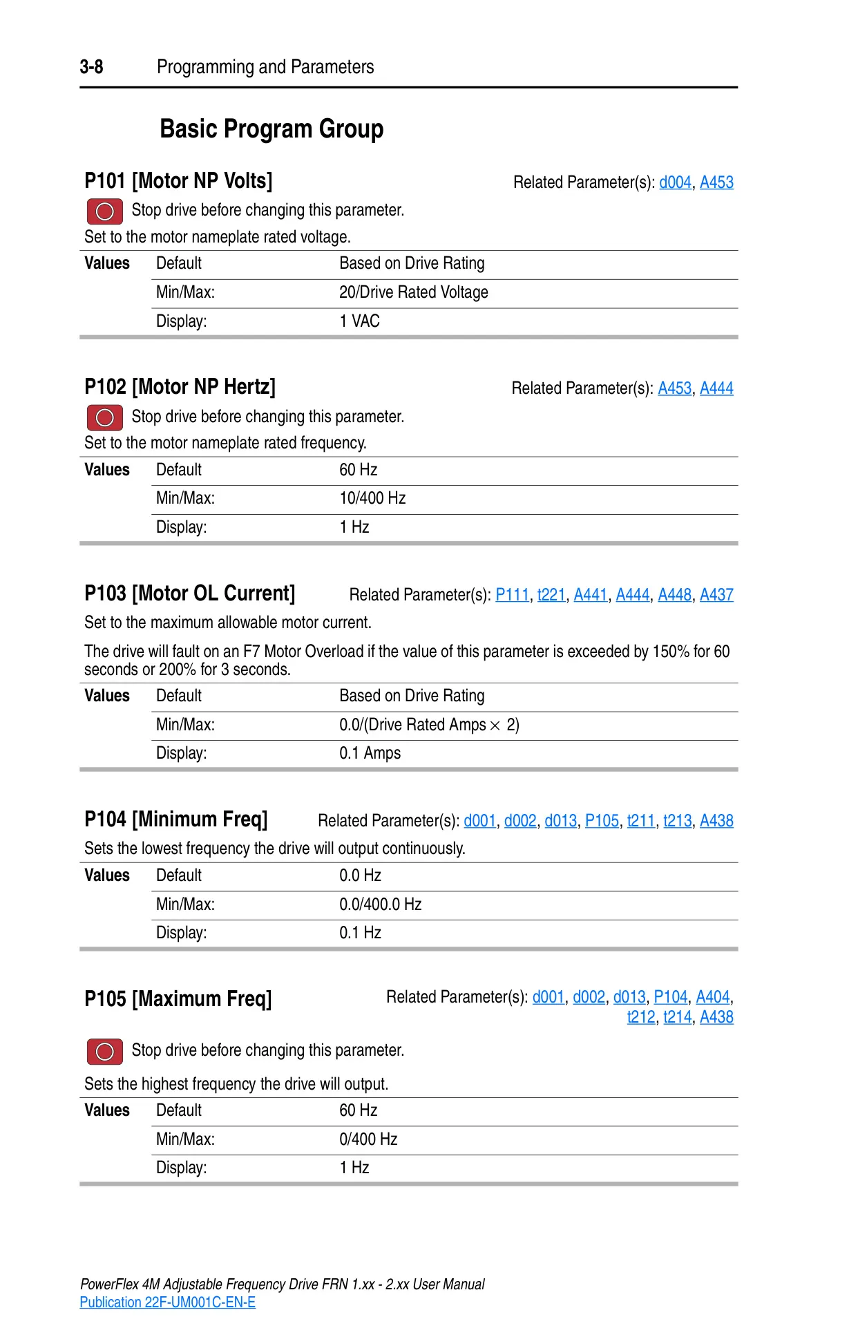
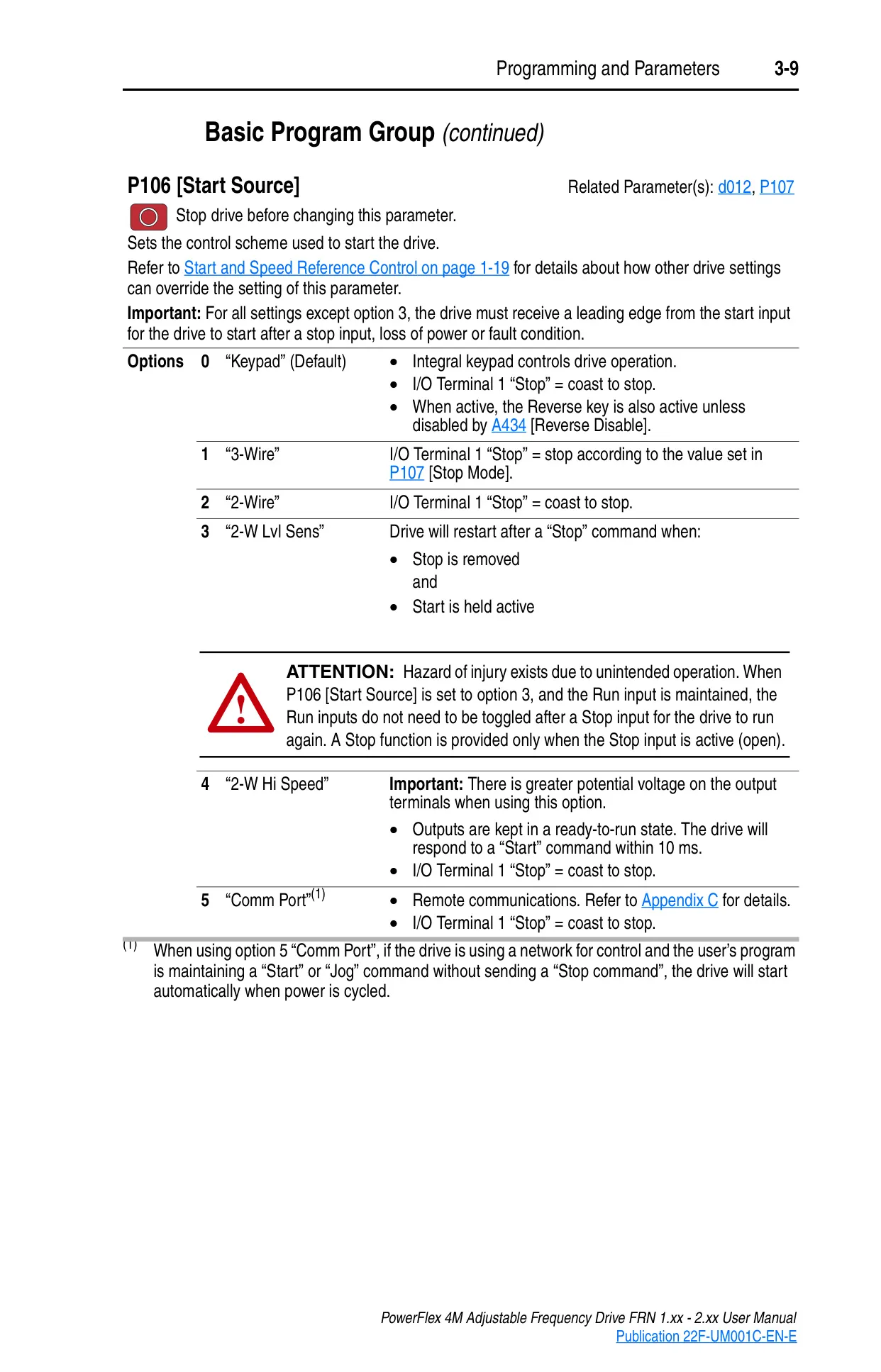
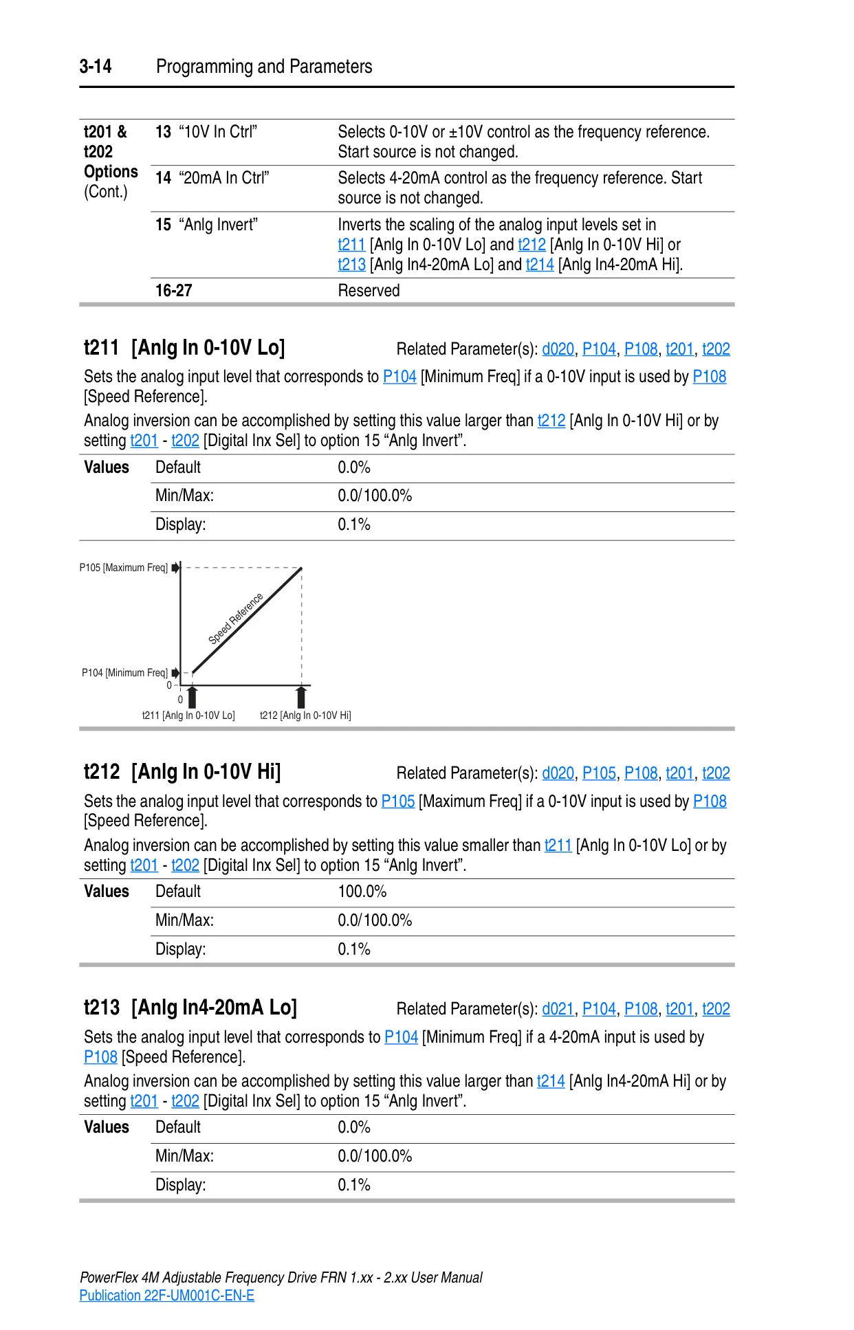
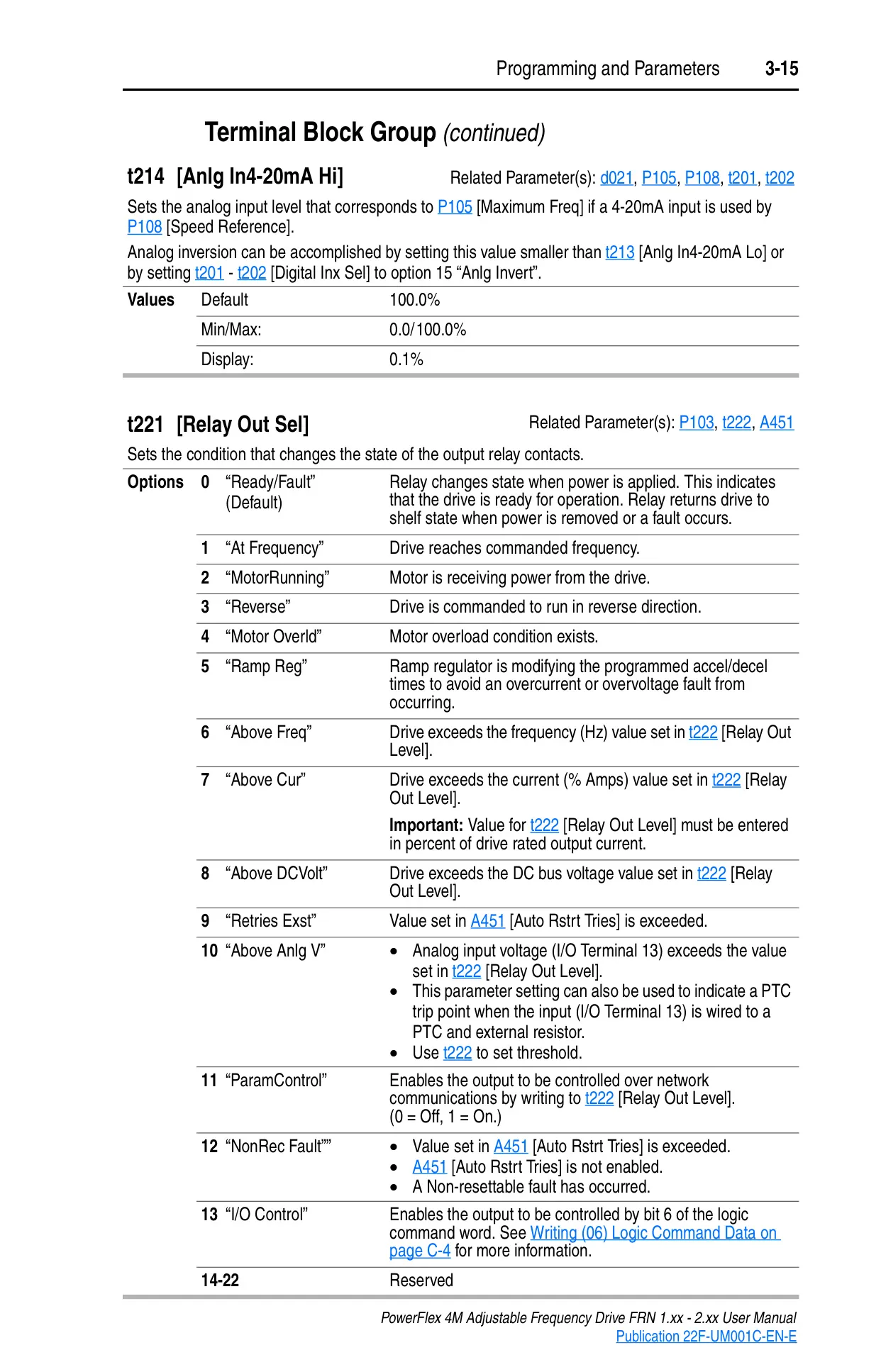
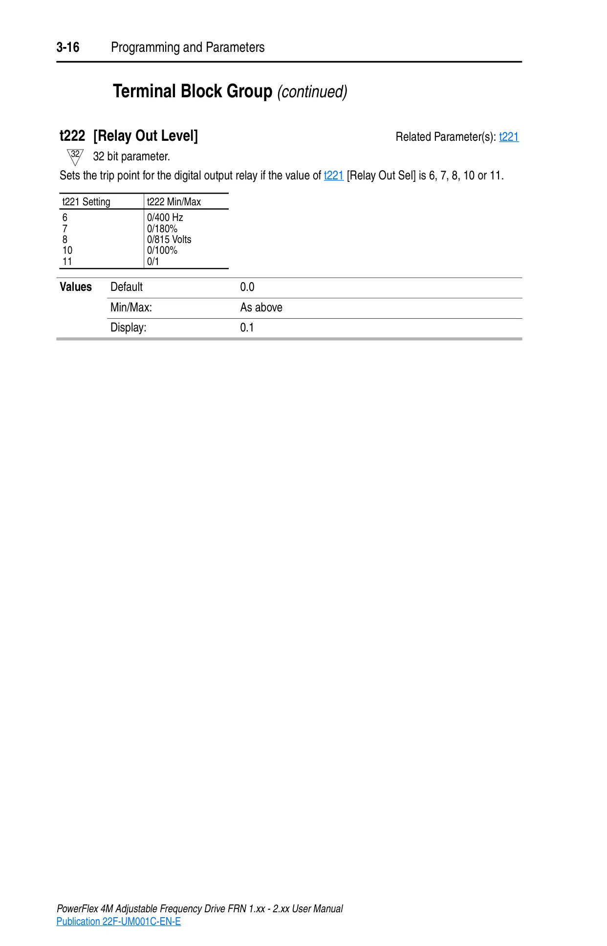
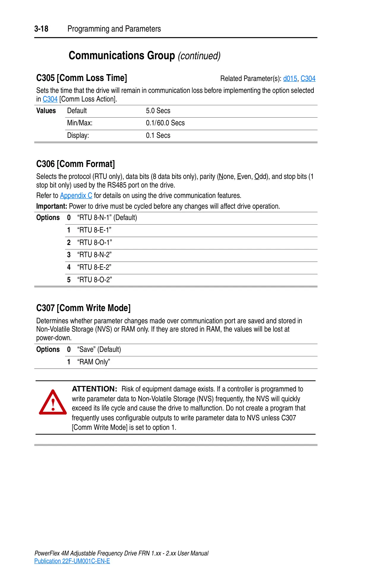
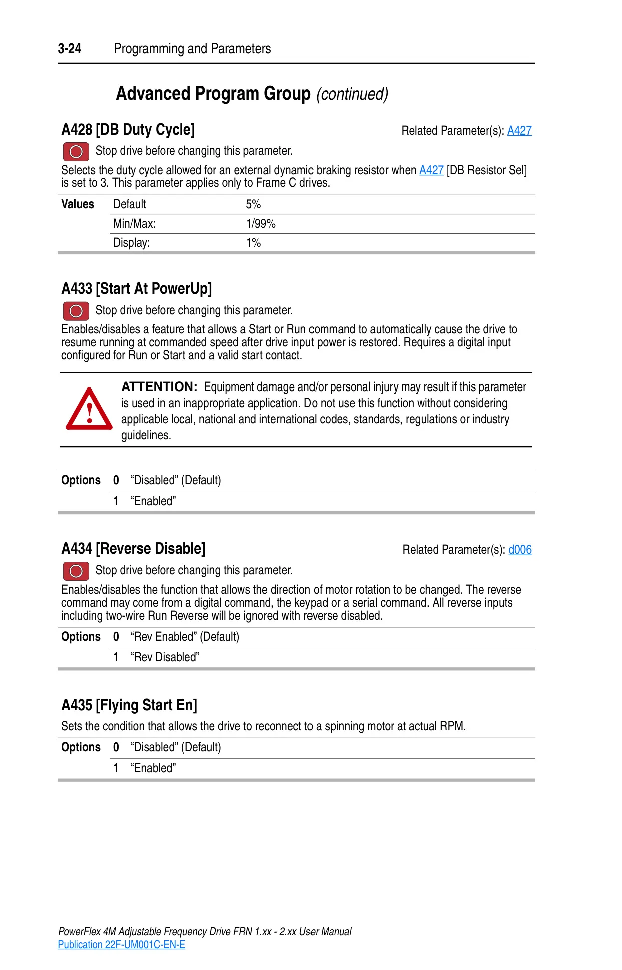
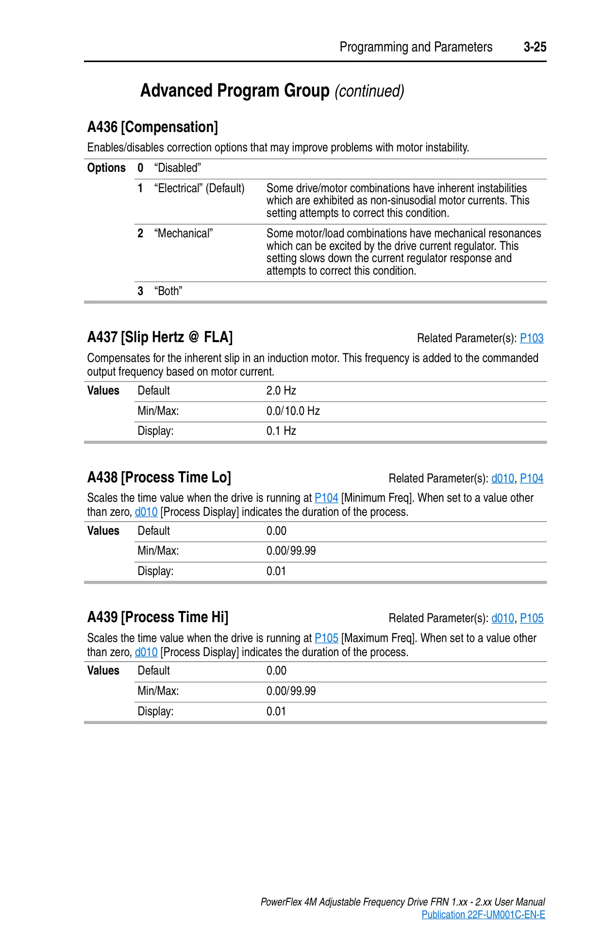
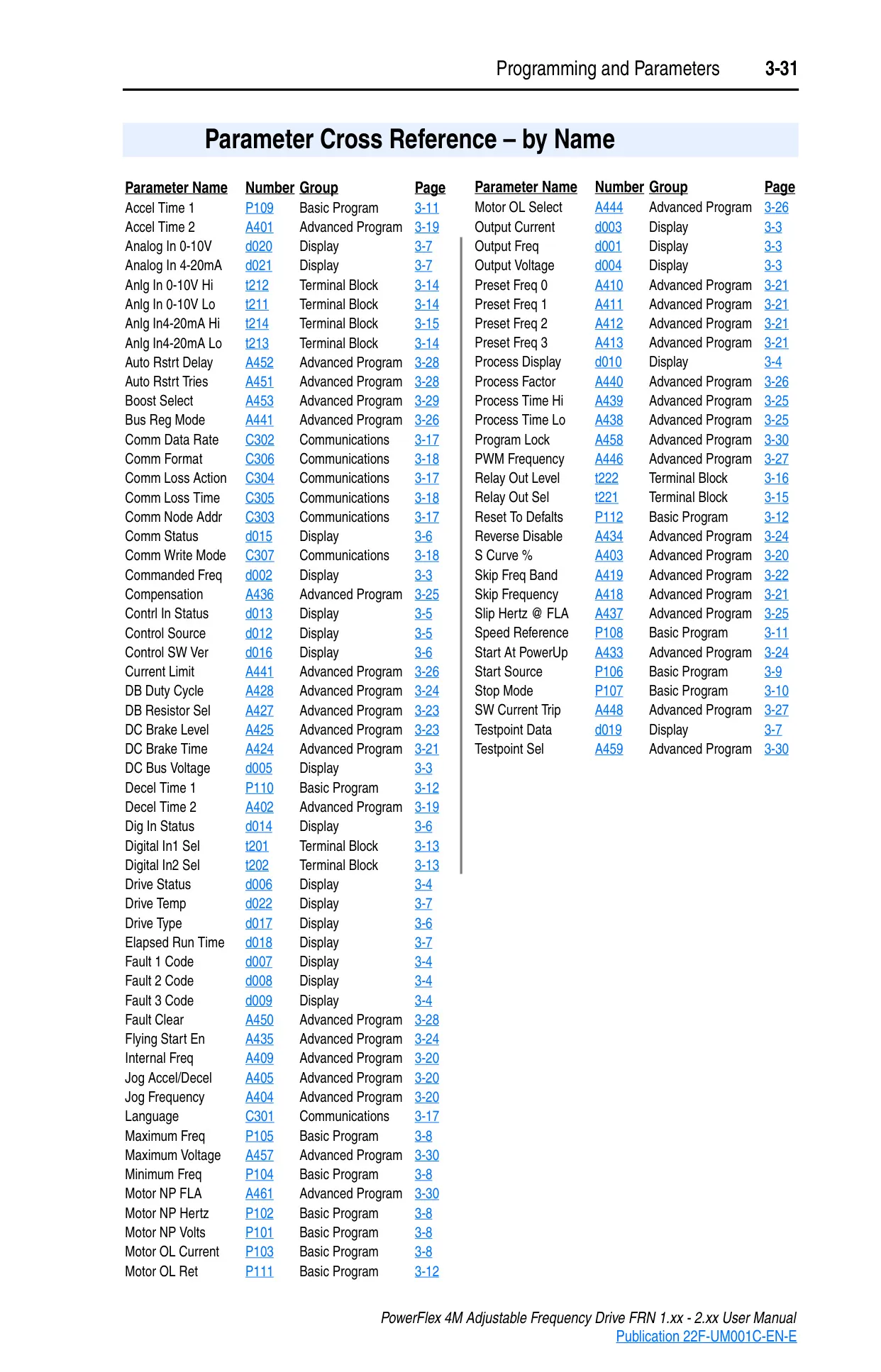
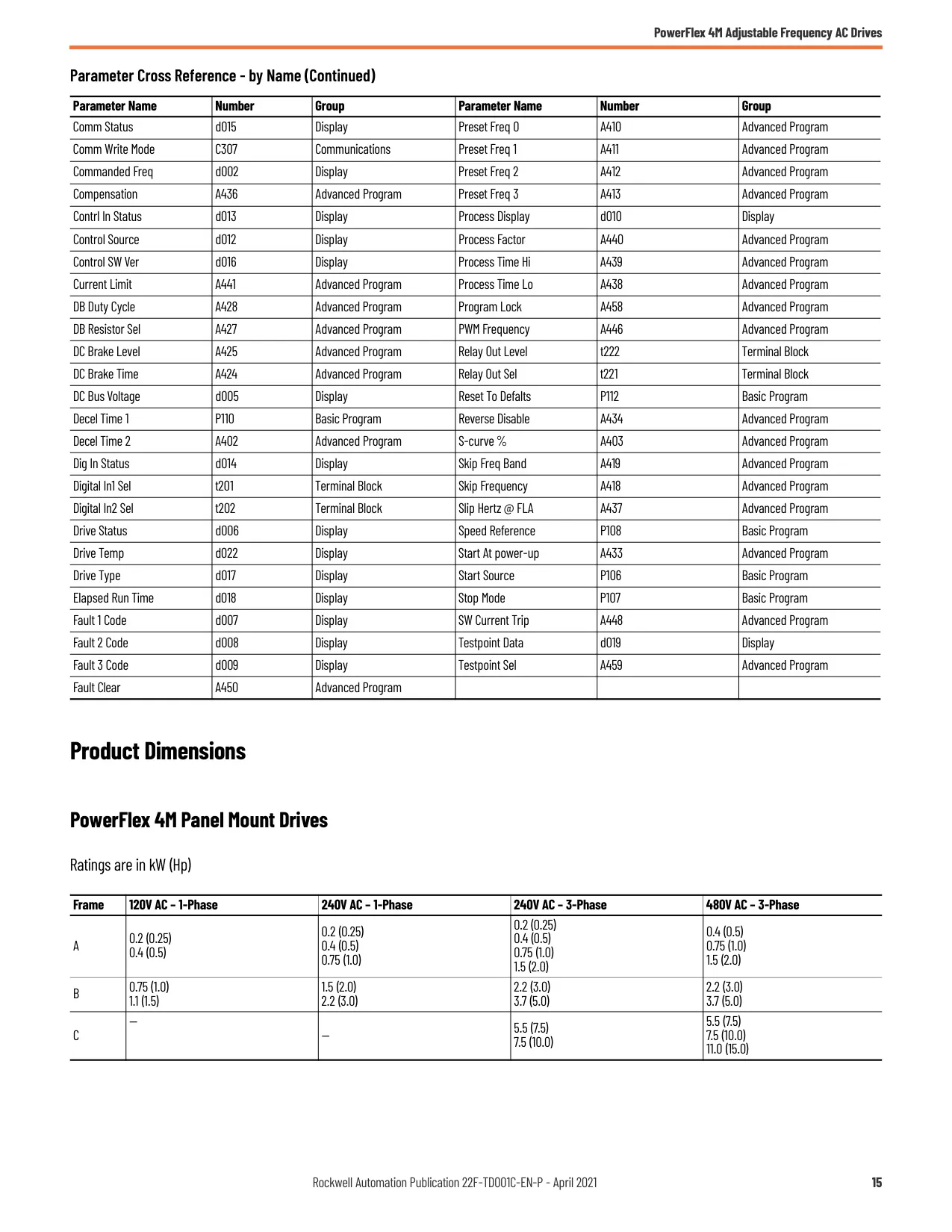
Operation and programming are facilitated by an intuitive integral keypad, enabling local control over start, stop, direction, and speed. Parameters are logically organized into Display, Basic Program, Terminal Block, Communications, and Advanced Program groups, allowing users to view operating conditions and customize drive behavior easily. The process for viewing and editing parameters is straightforward.
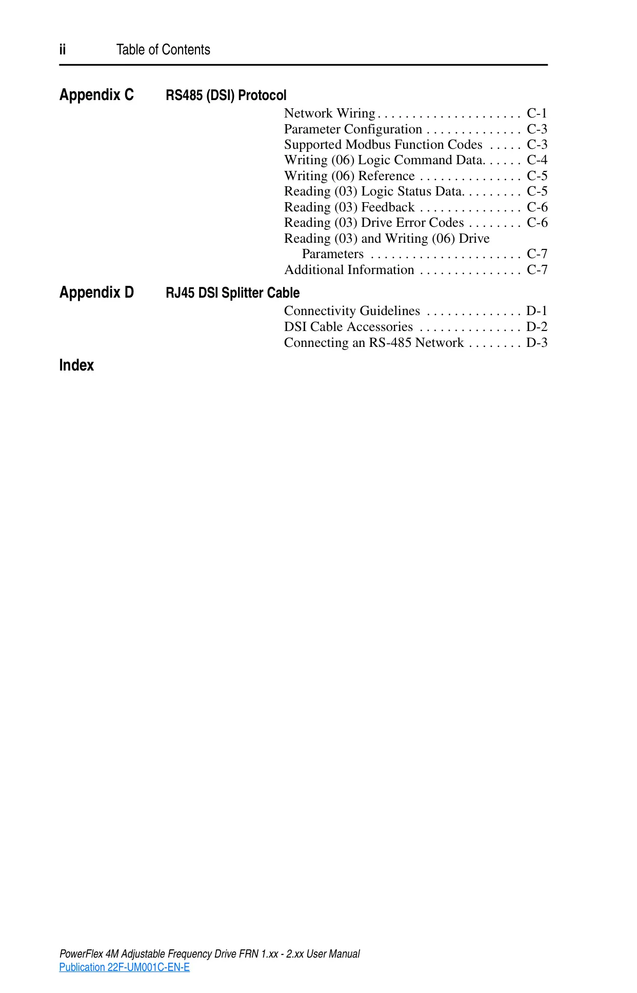
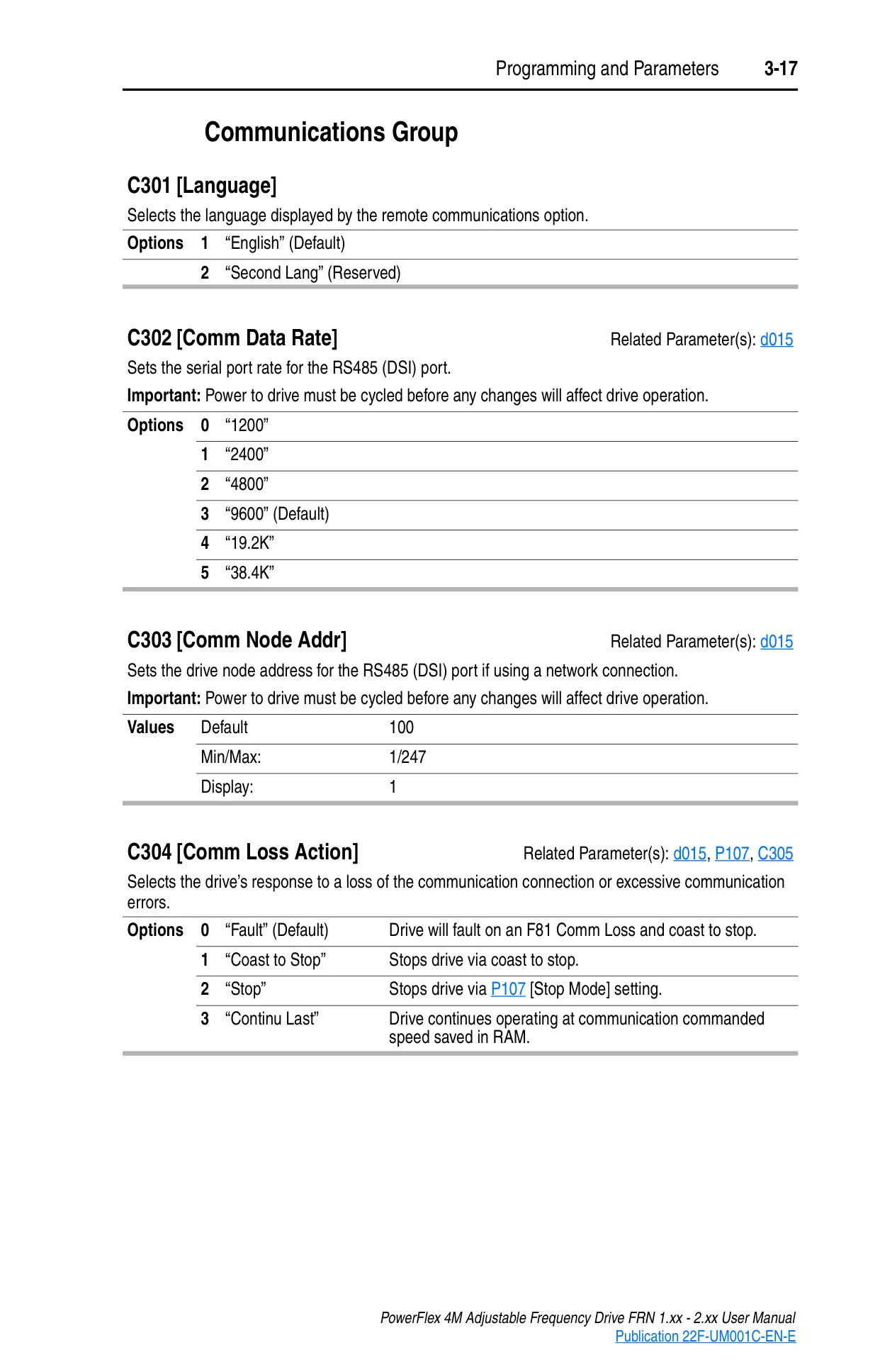
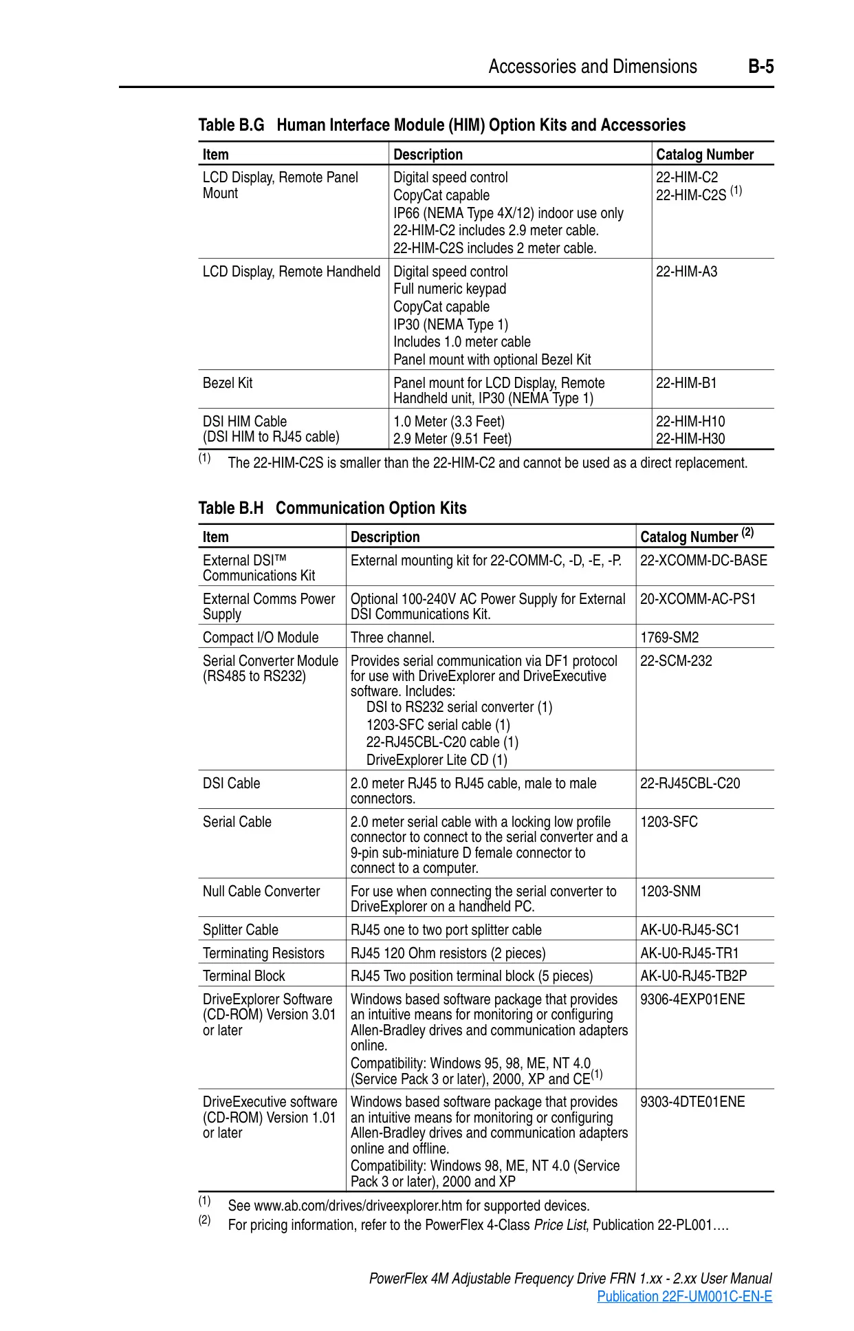
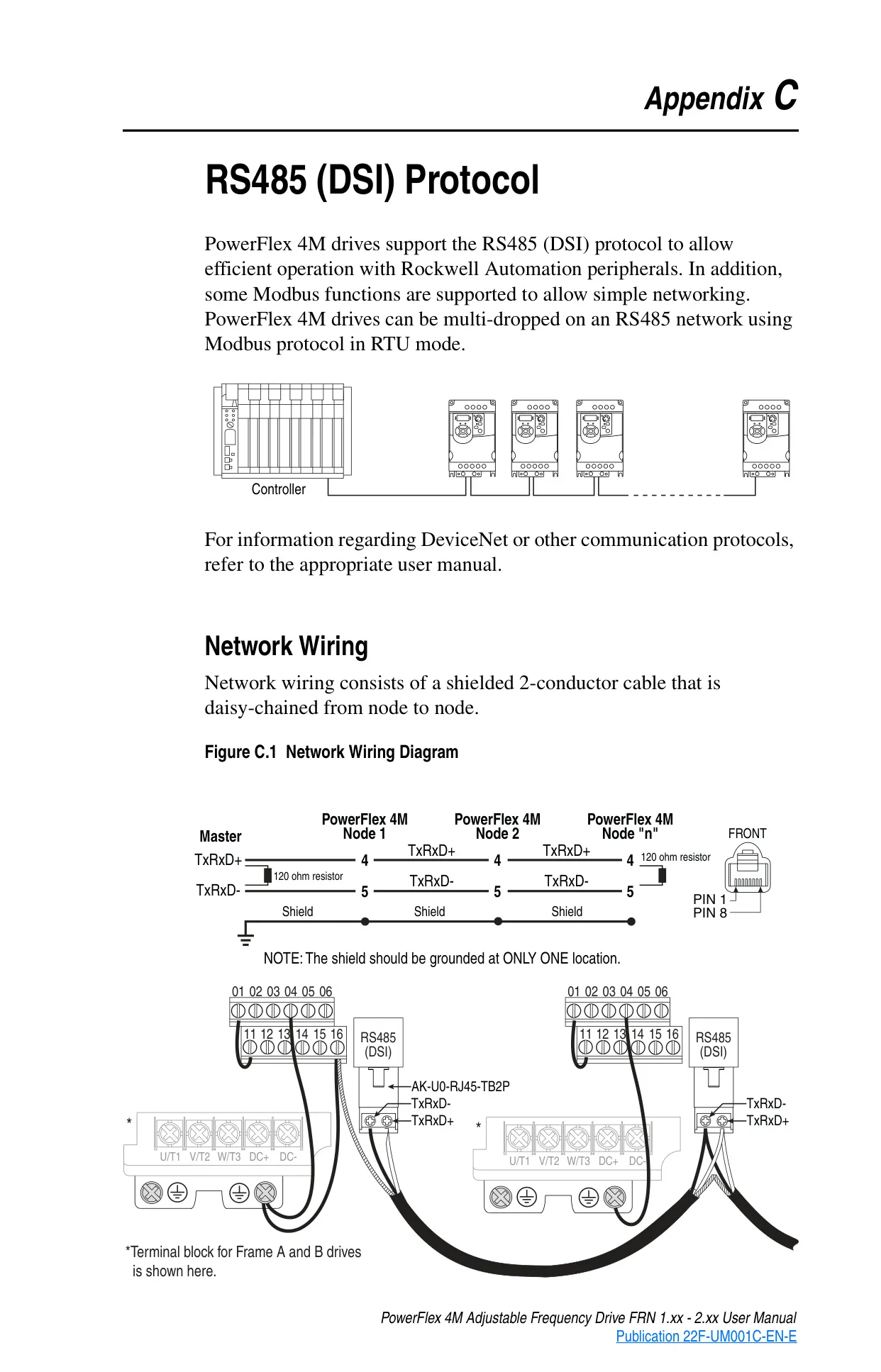
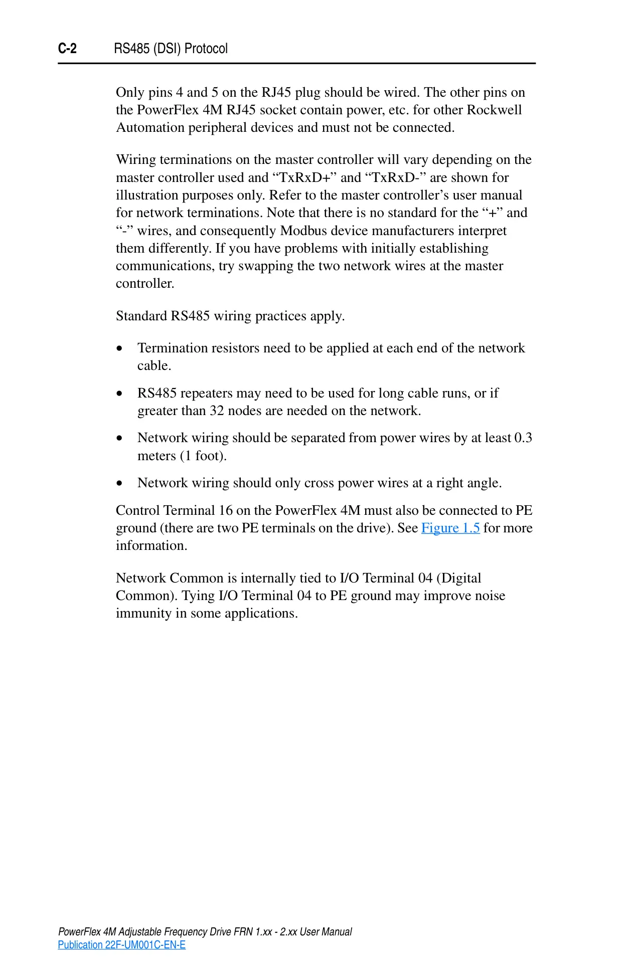
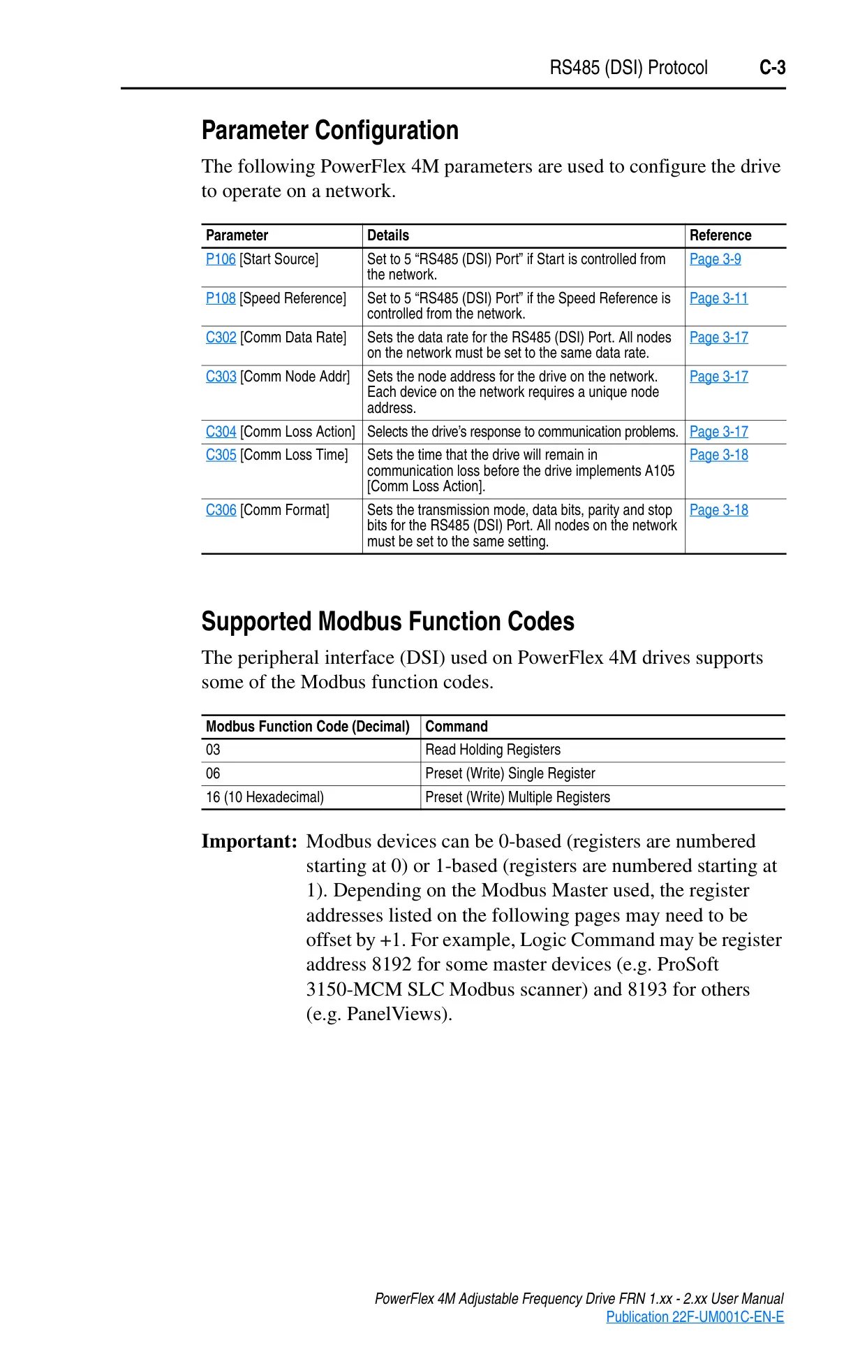
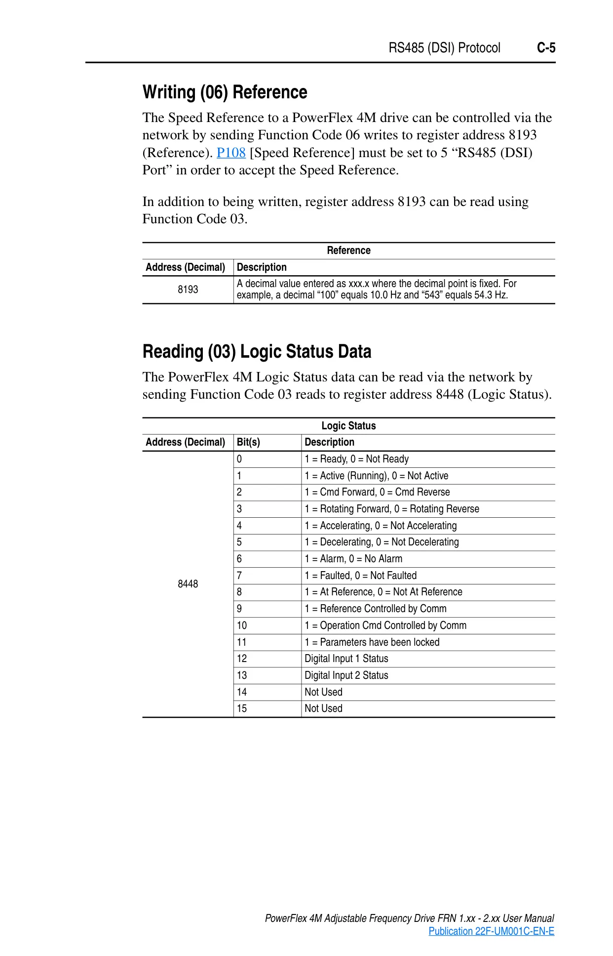
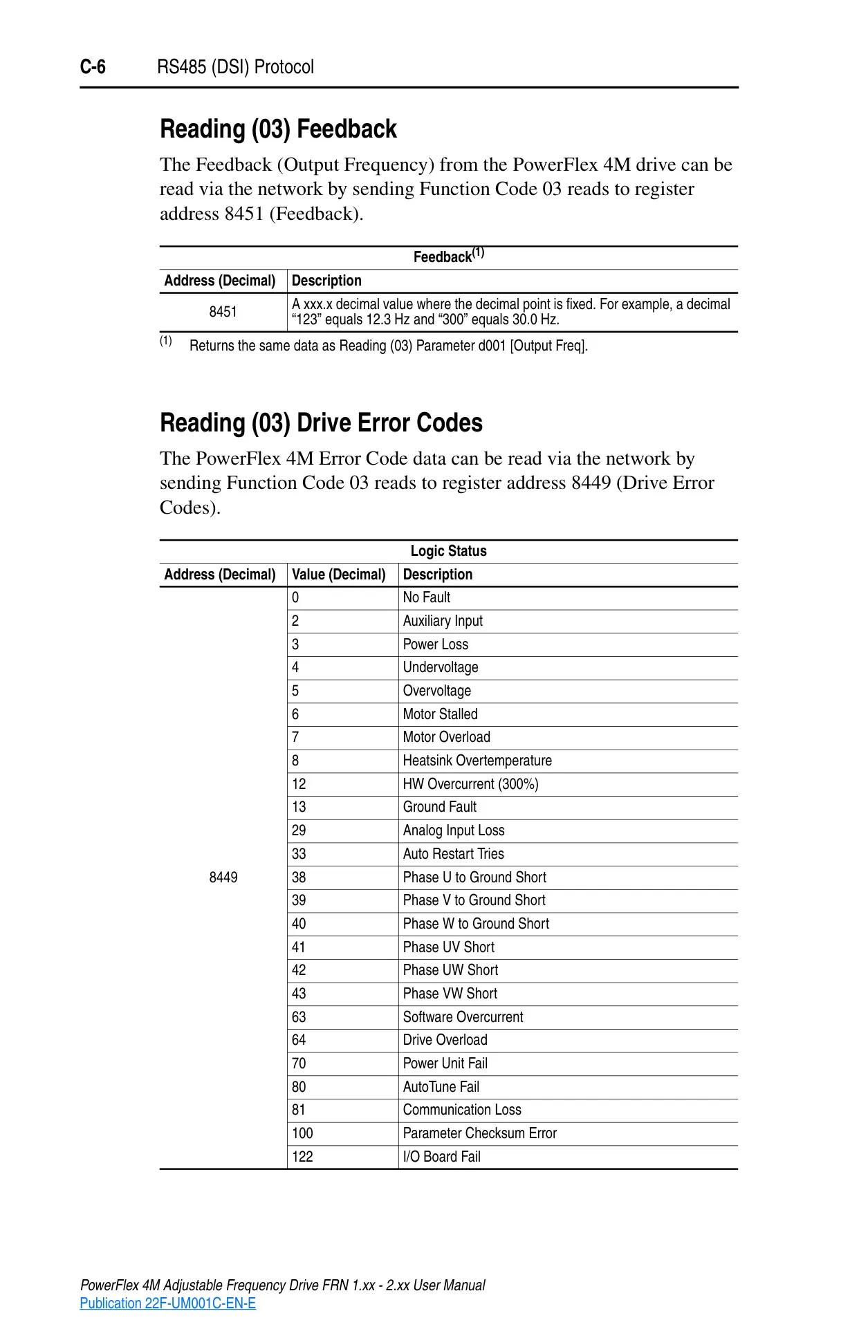
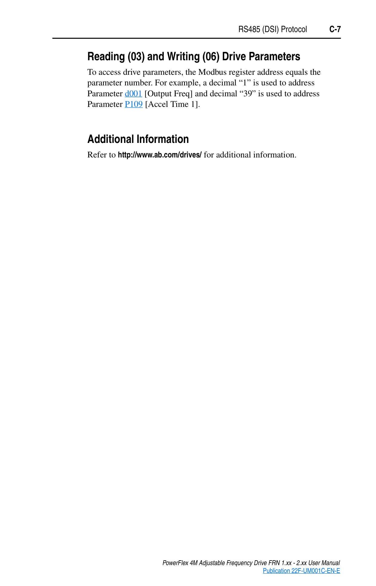
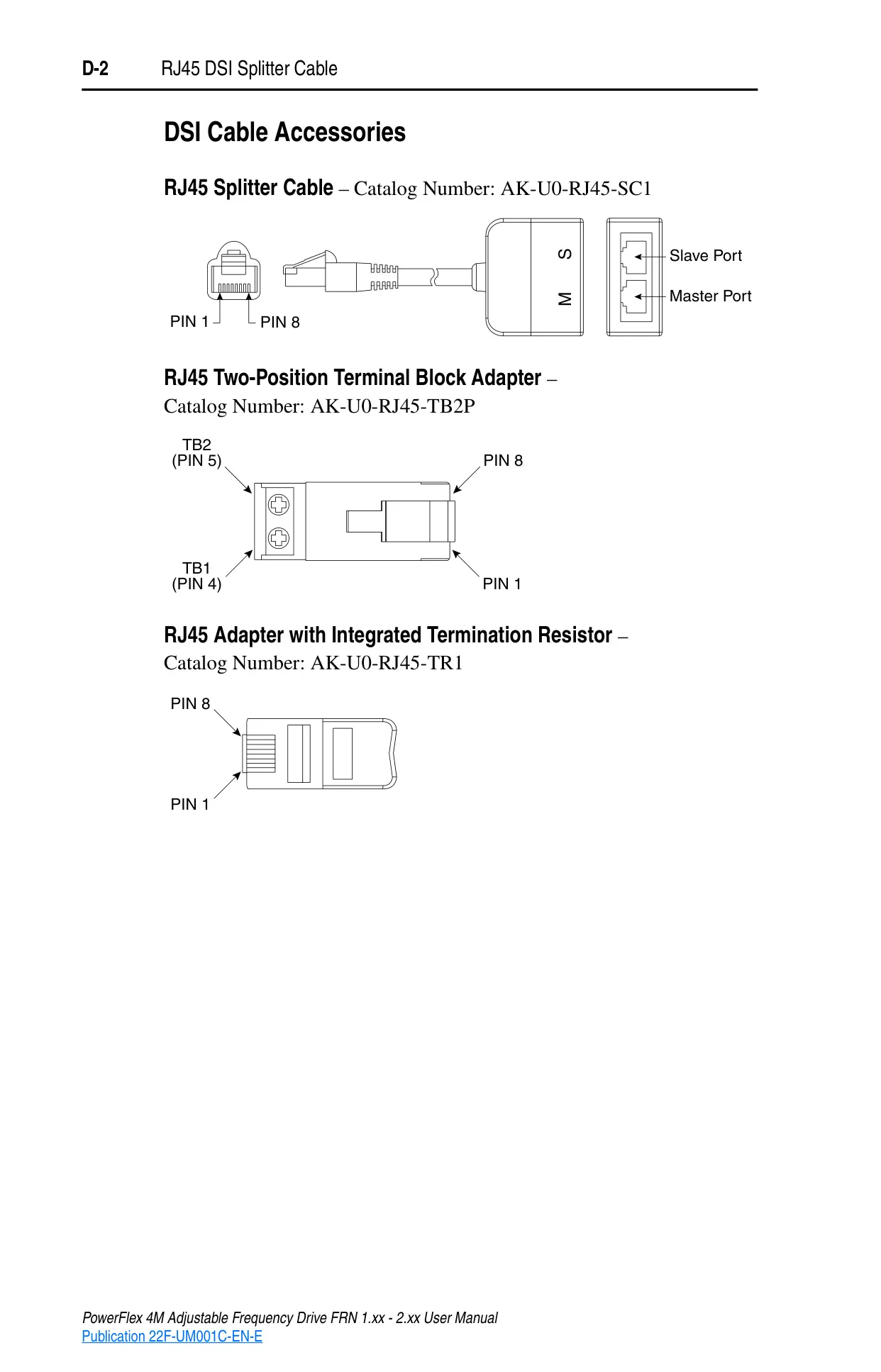
Connectivity extends to RS485 (DSI) protocol support, enabling efficient communication with Rockwell Automation peripherals and Modbus networks. The manual details network wiring, parameter configuration for communication, and supported Modbus function codes. Accessories like the RJ45 DSI Splitter Cable expand peripheral connection options, allowing up to two devices per drive.
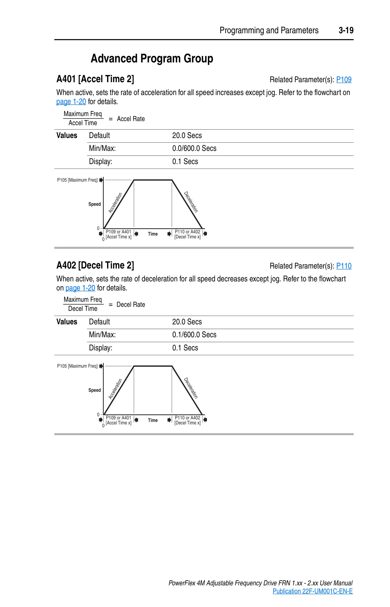
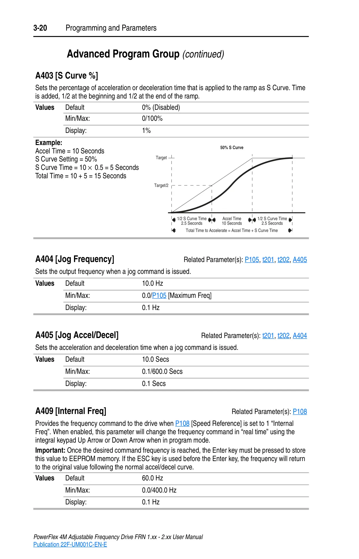
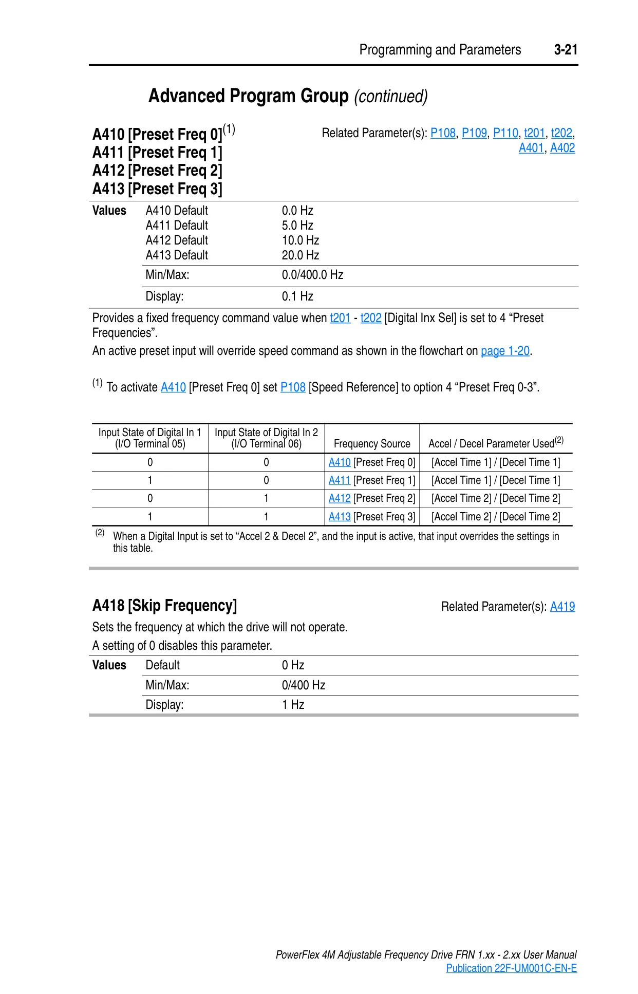
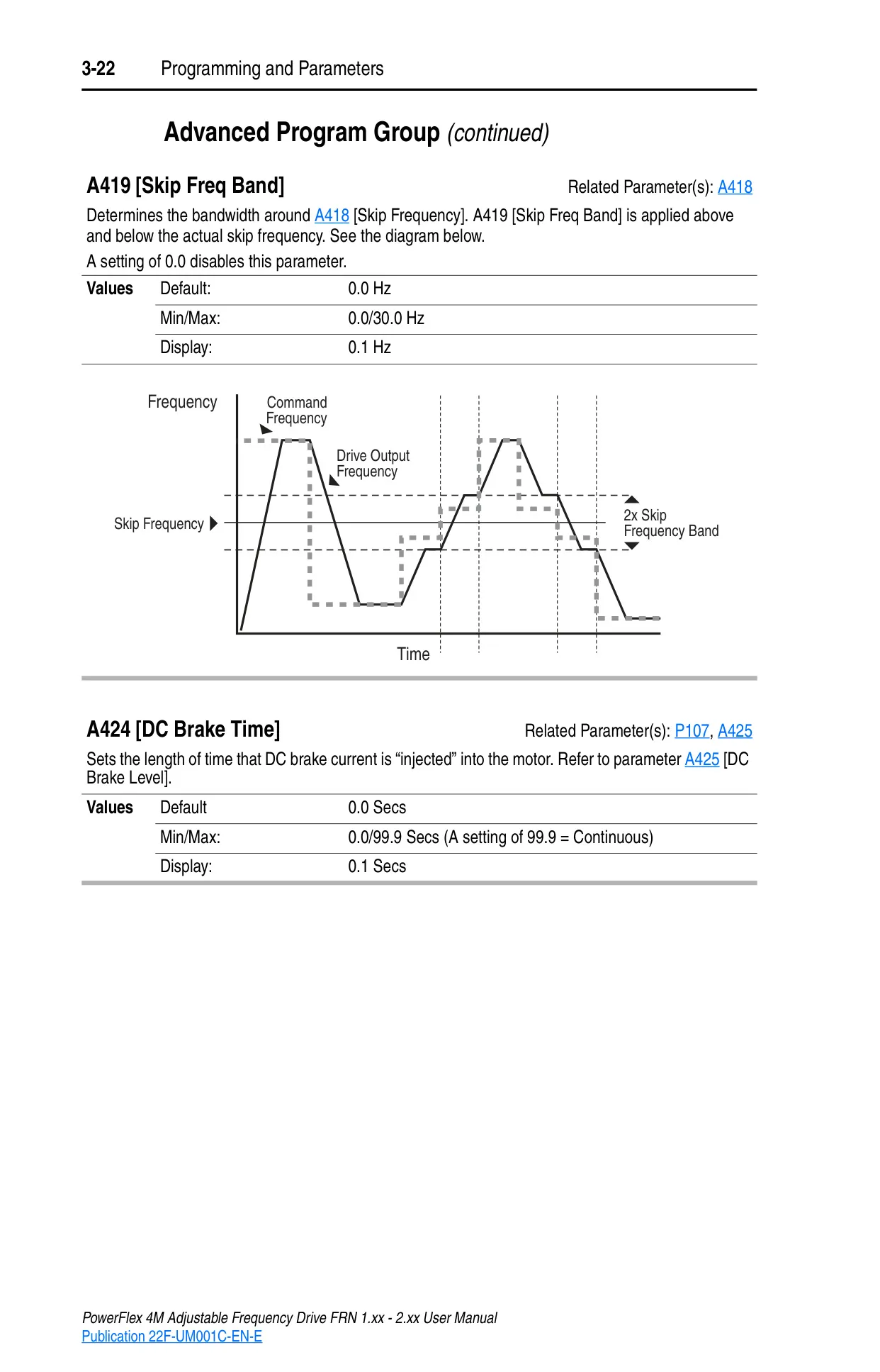
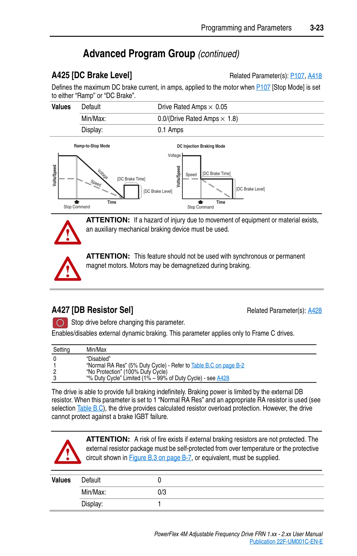
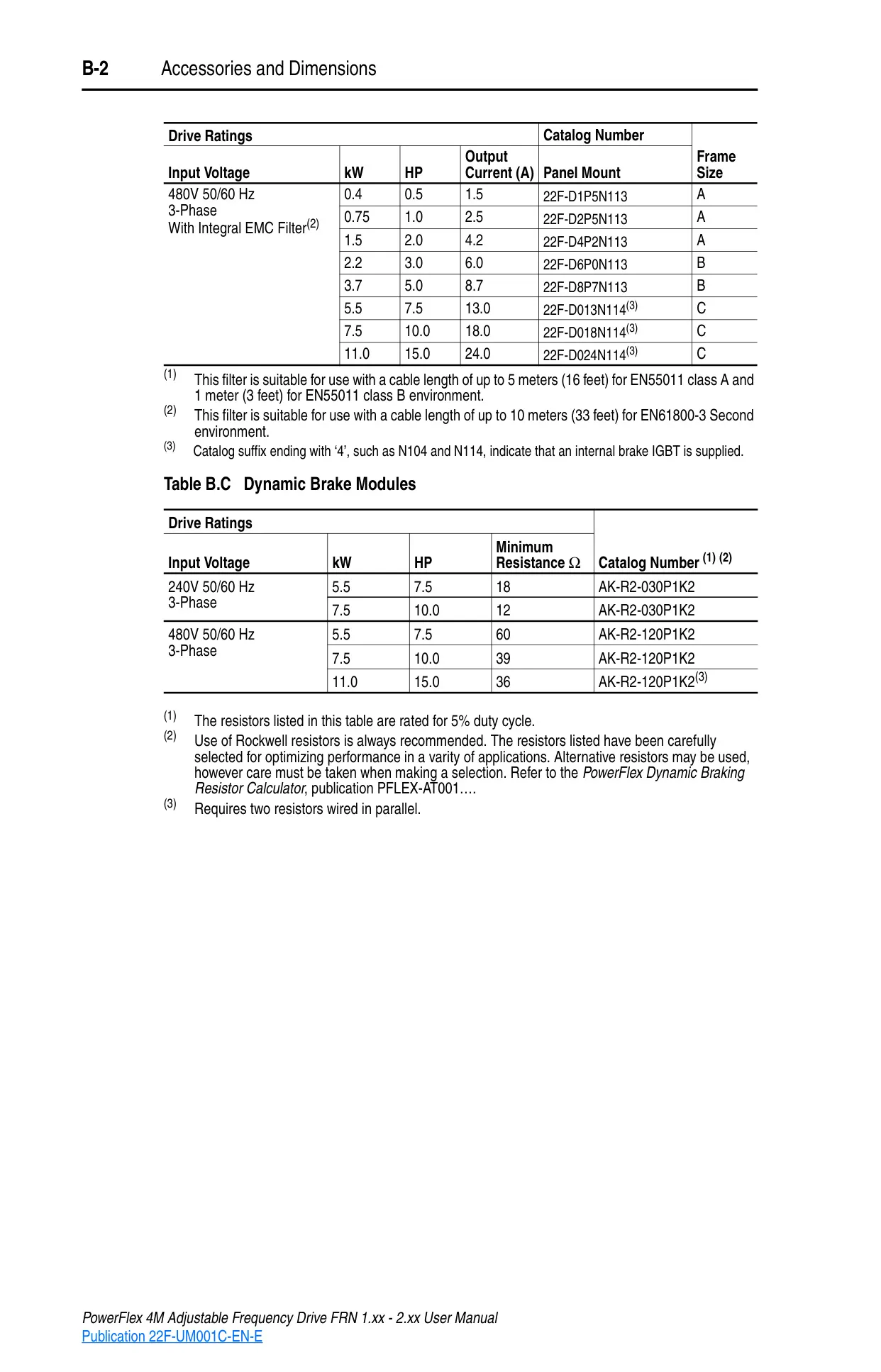
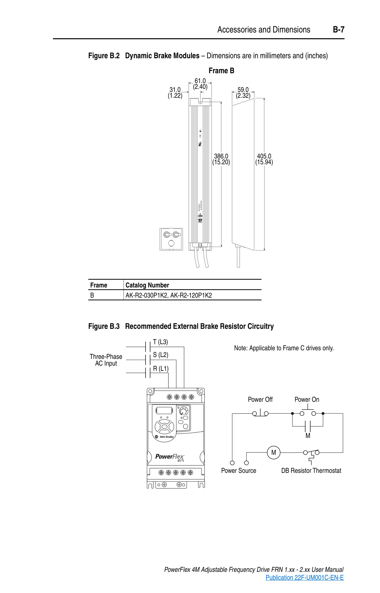
Advanced features include dynamic braking for controlled deceleration (with internal IGBTs on larger frames and options for external resistors), S-curve acceleration/deceleration to smooth ramps, jog functions for precise motor movement, and preset frequencies for quick speed selection. The drive also incorporates skip frequency bands to avoid mechanical resonances, and a bus regulator mode to prevent overvoltage faults during aggressive decelerations.
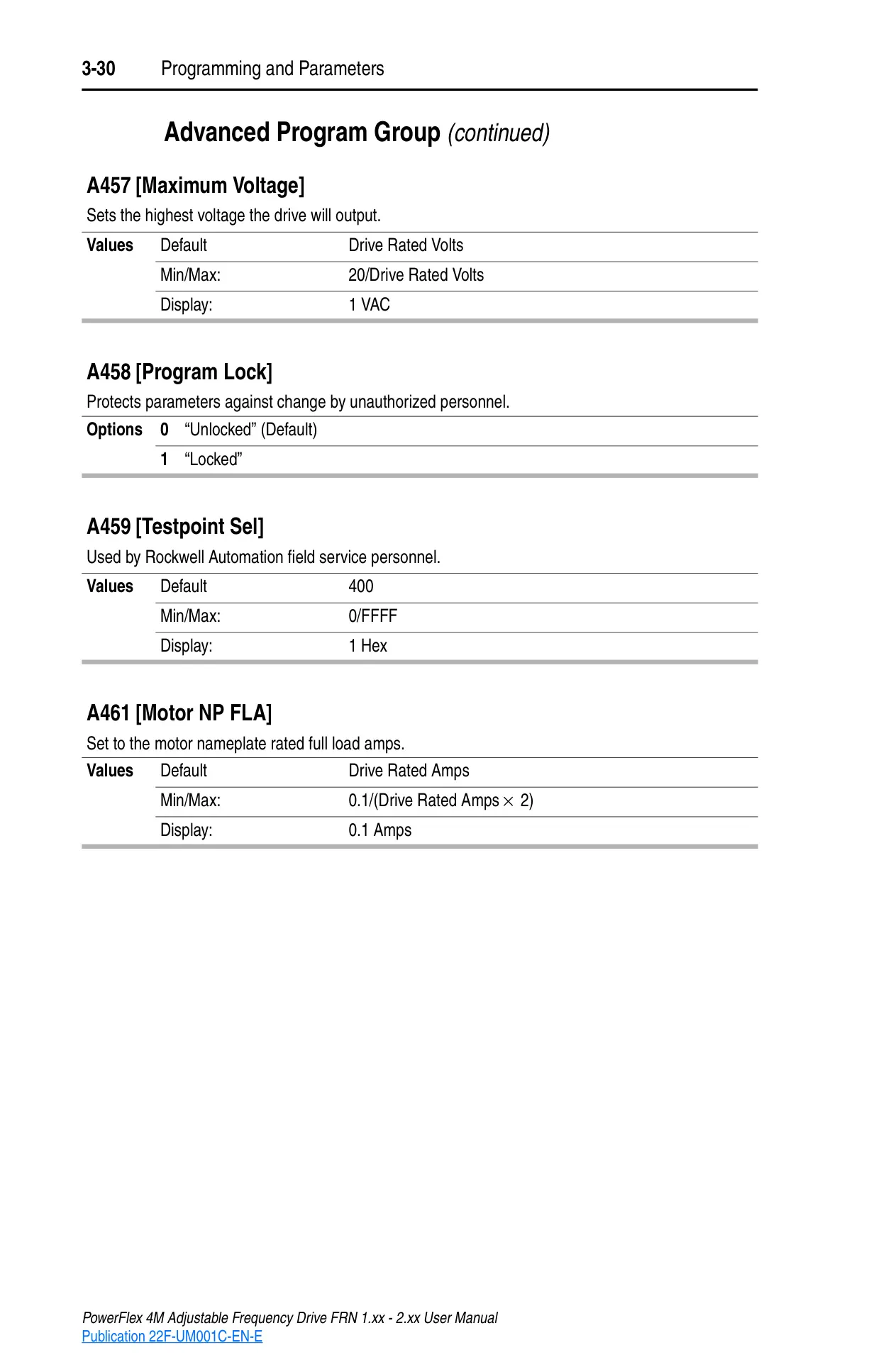
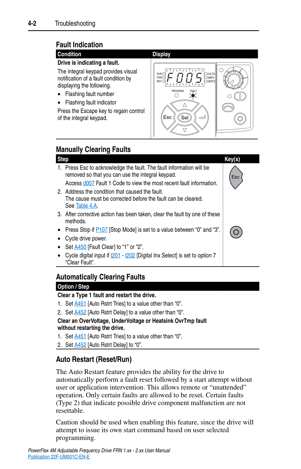
The PowerFlex 4M also boasts an "Auto Restart" feature, allowing the drive to automatically attempt to clear and restart after certain fault conditions, enhancing system uptime in remote or unattended operations. A parameter lock feature protects configurations from unauthorized changes, underscoring the drive's comprehensive design for industrial environments.
Frequently Asked Questions (FAQs)
Can't find the answer you need? Here are some frequently asked questions about the Allen-Bradley Powerflex 4M, and we answer them below.