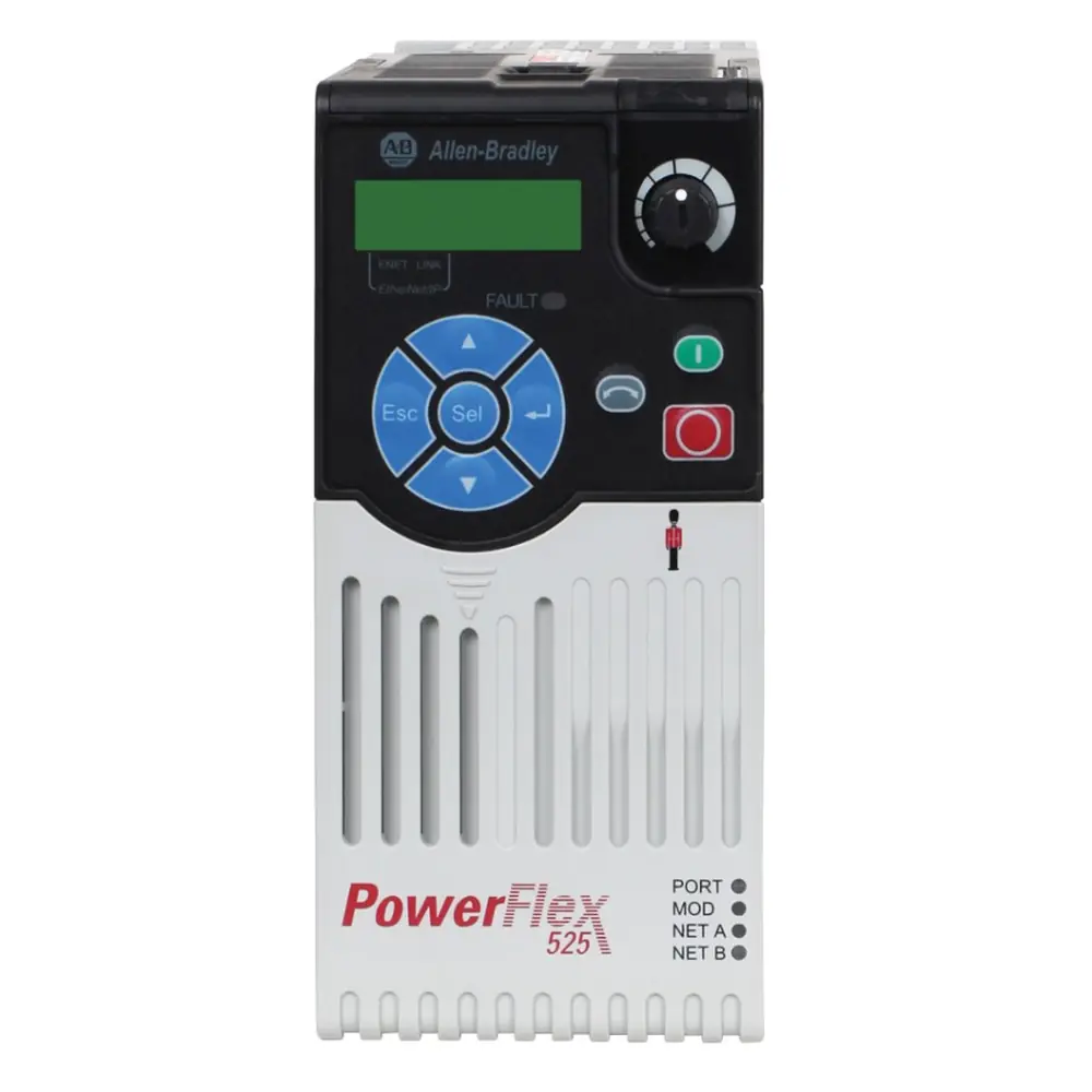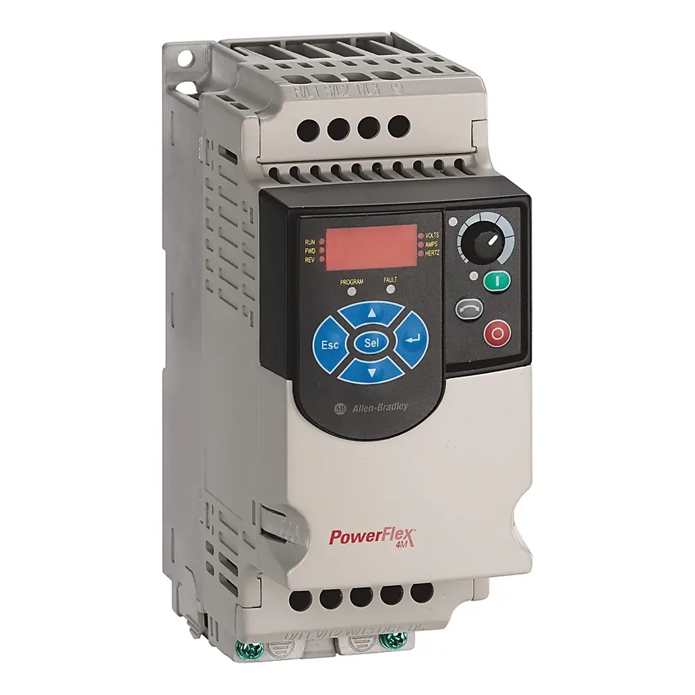
Allen-Bradley Powerflex 40 VFD Instruction Manual
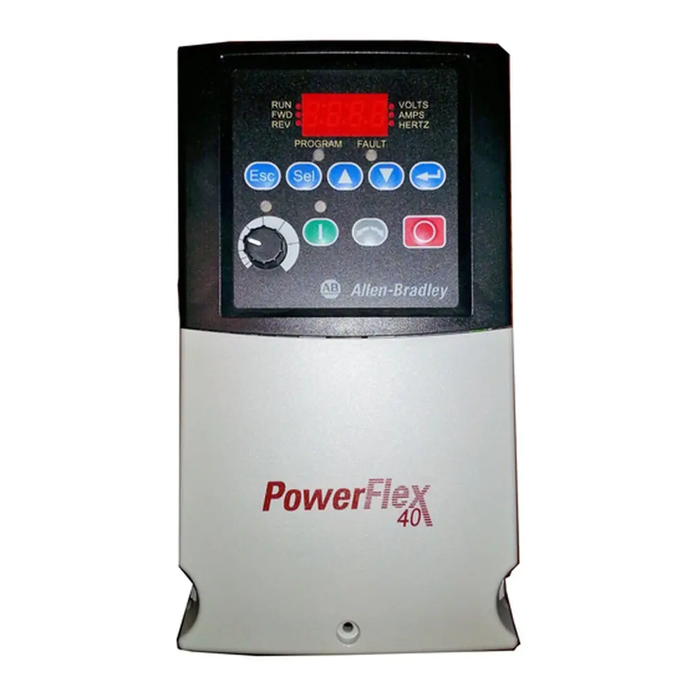
Allen-Bradley Powerflex 40 VFD










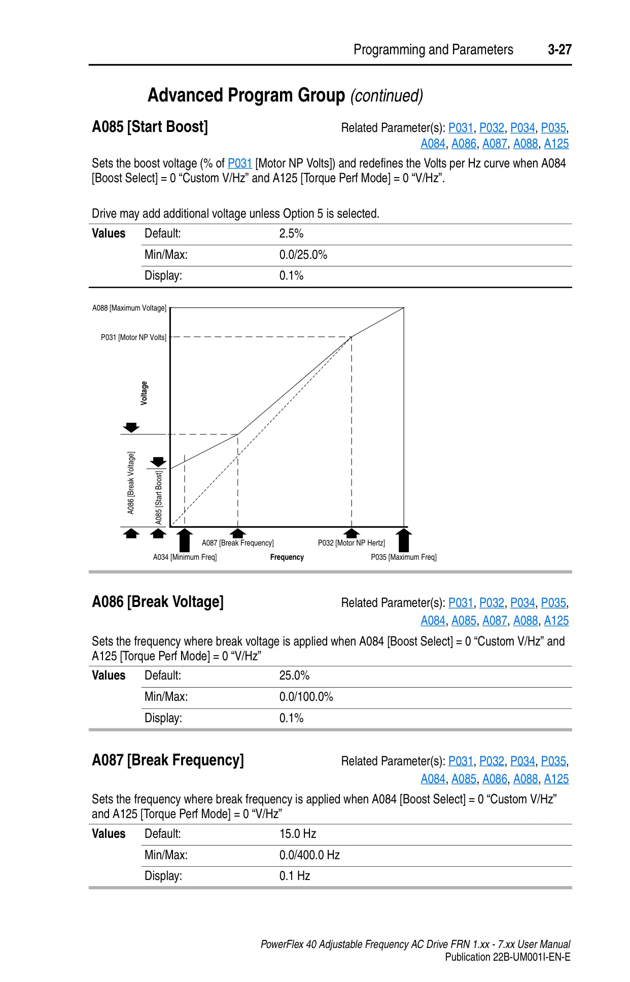
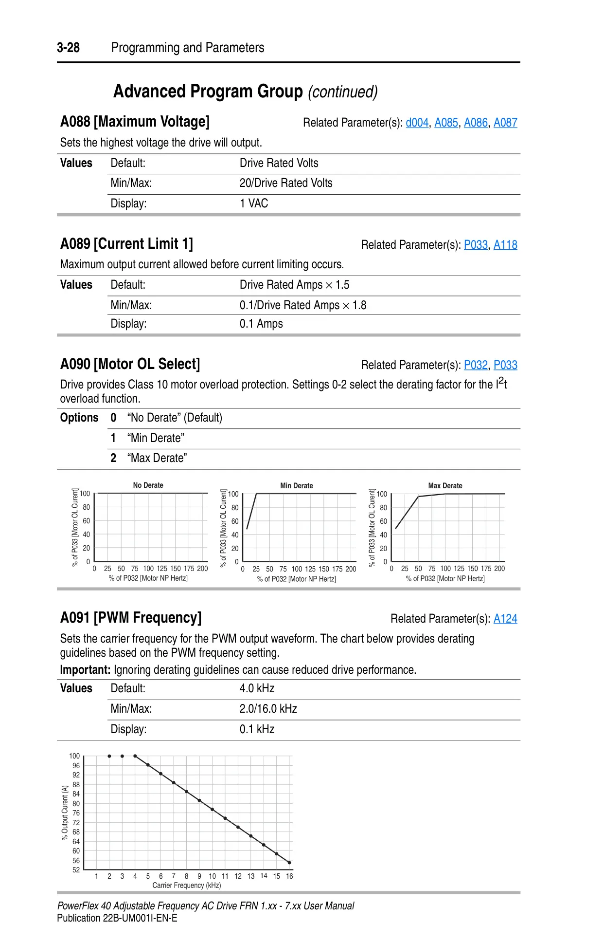

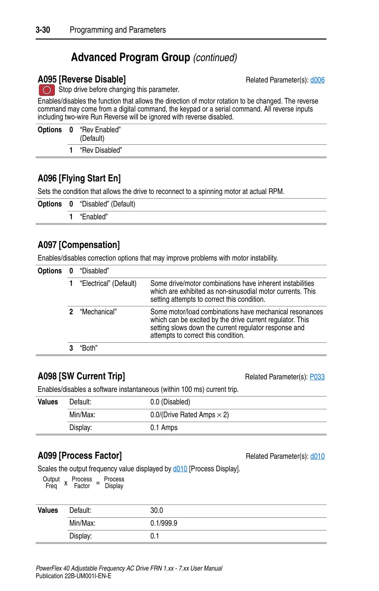
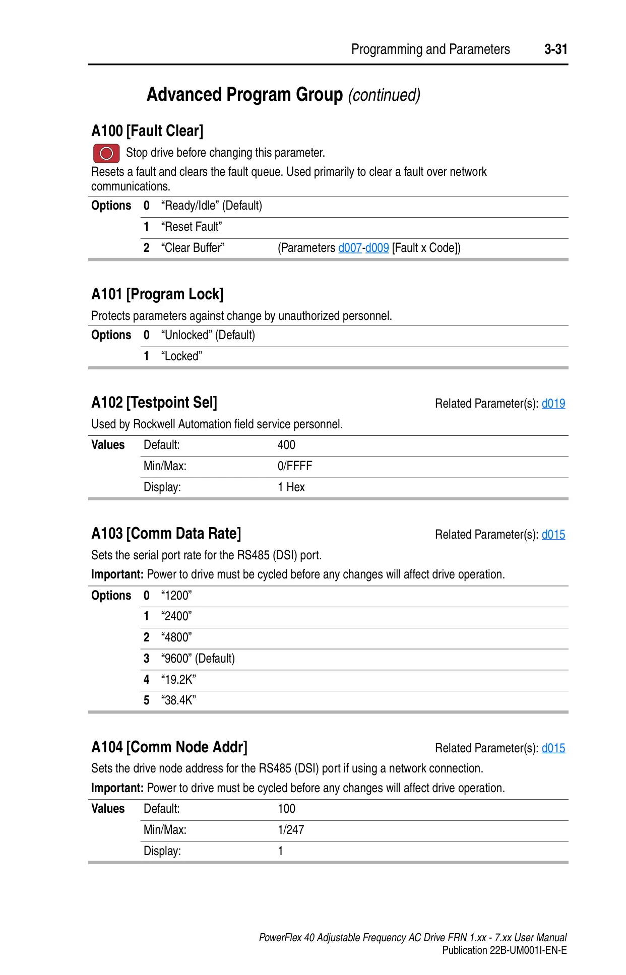







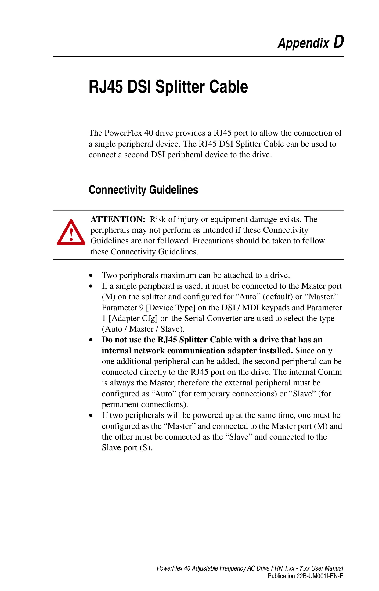
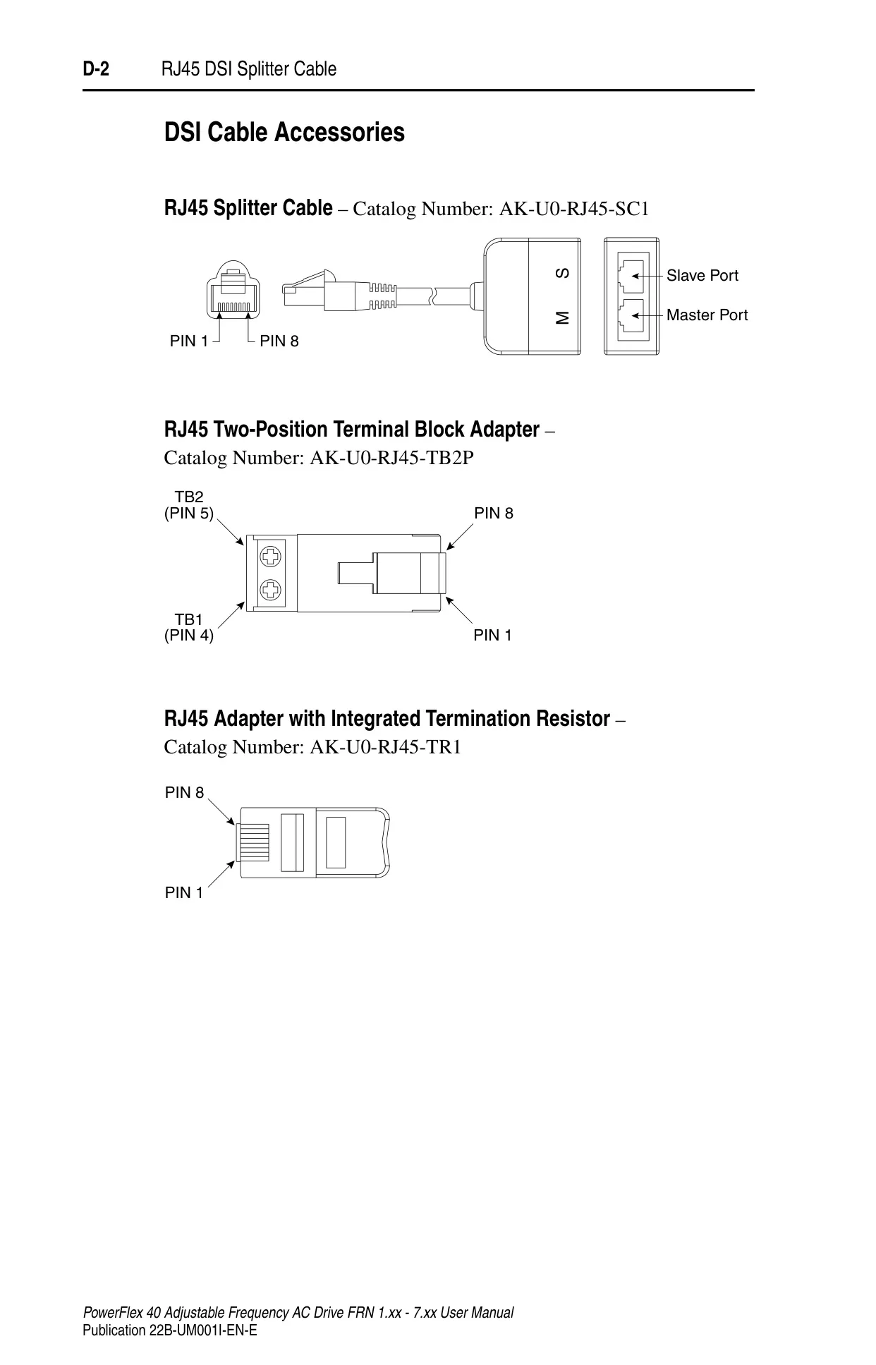

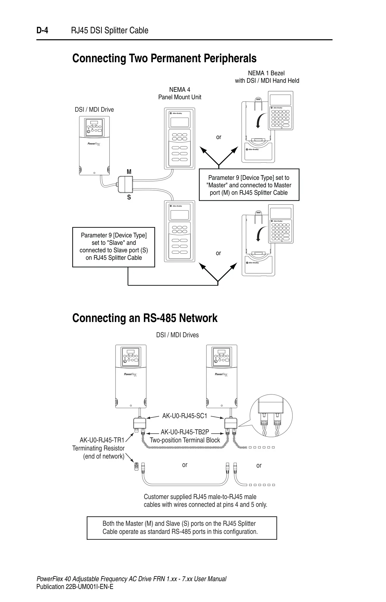
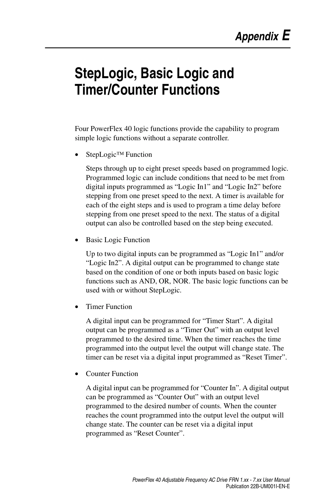






Allen-Bradley Powerflex 40 VFD

Allen-Bradley Powerflex 40 VFD


Allen-Bradley Powerflex 40 VFD Instructions
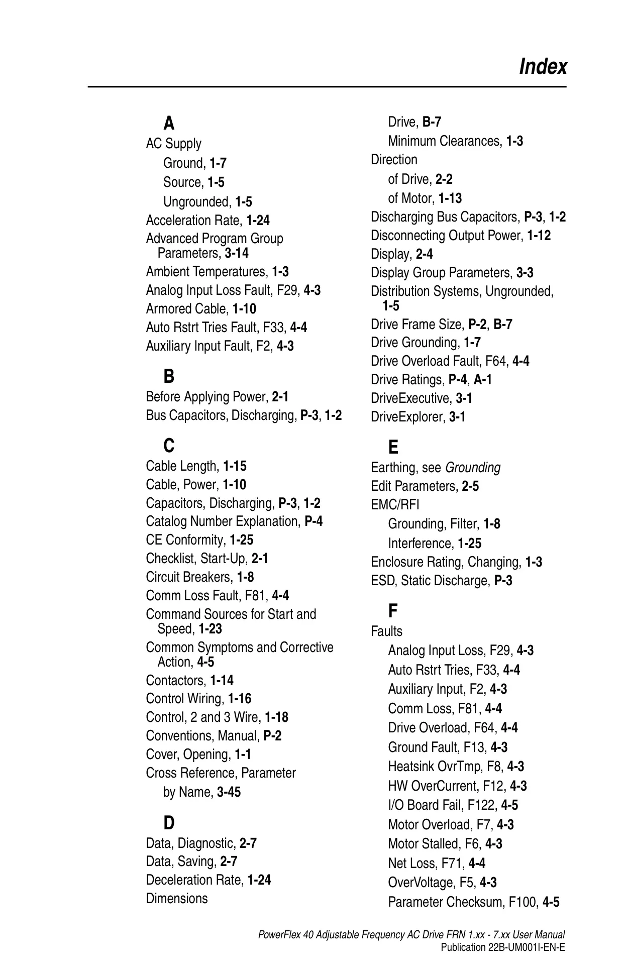
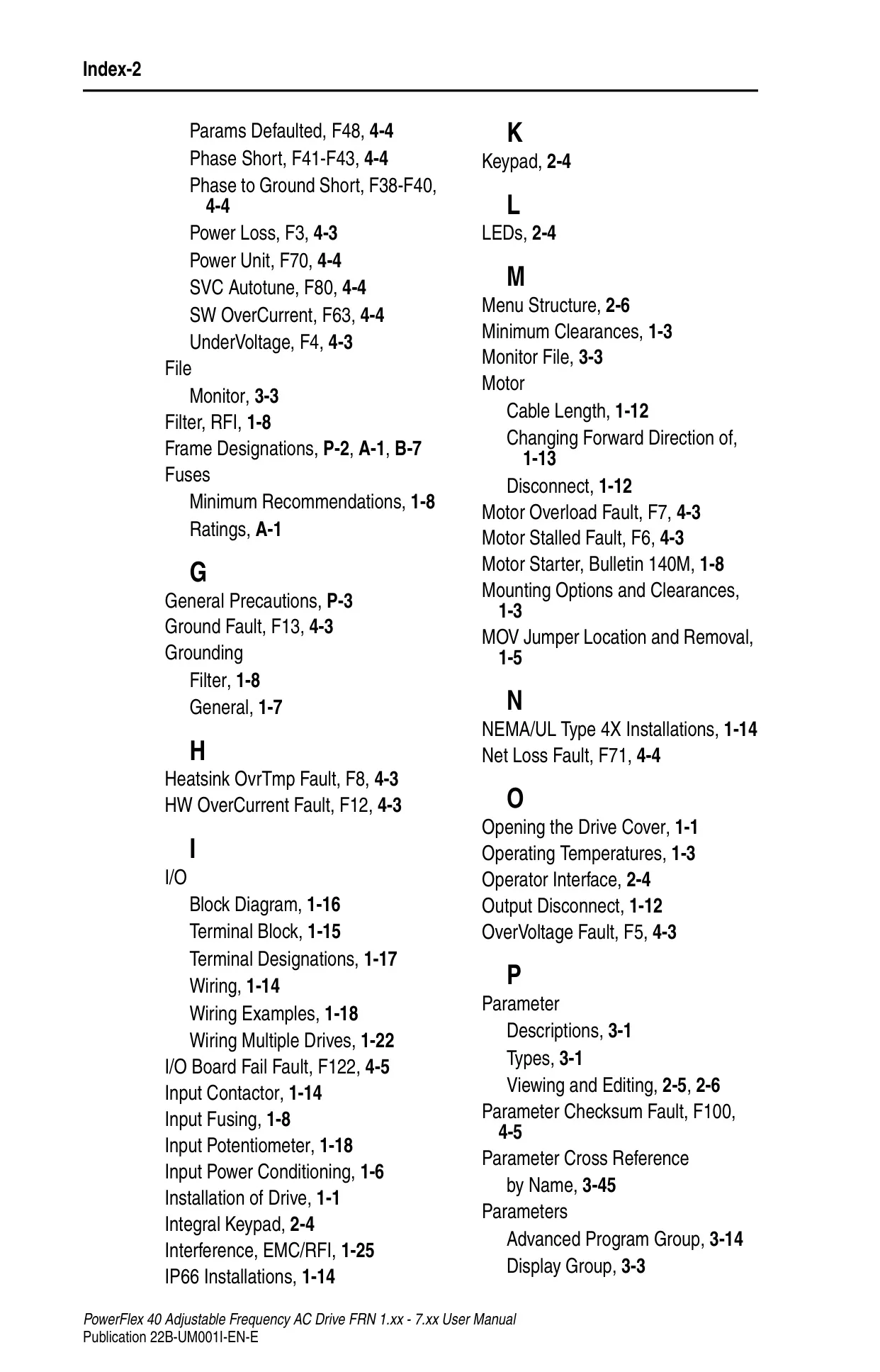
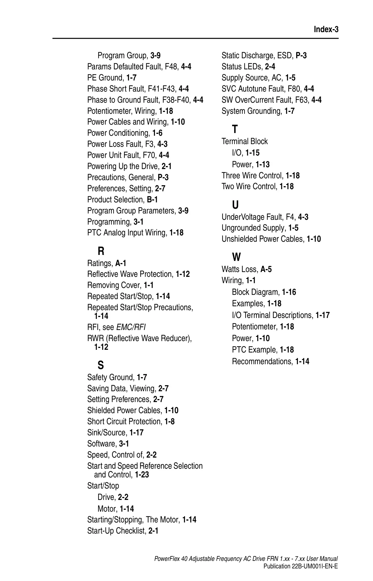
Here we offer the Allen-Bradley Powerflex 40 VFD manual completely free and in English. We have cataloged this manual in the Variable Frequency Drives section on Manualverse, and it has been rated by 1 users with an average rating of 5. If you have any specific questions about Allen-Bradley Powerflex 40 VFD, we suggest checking the Frequently Asked Questions (FAQs) section of this manual.
Product Images

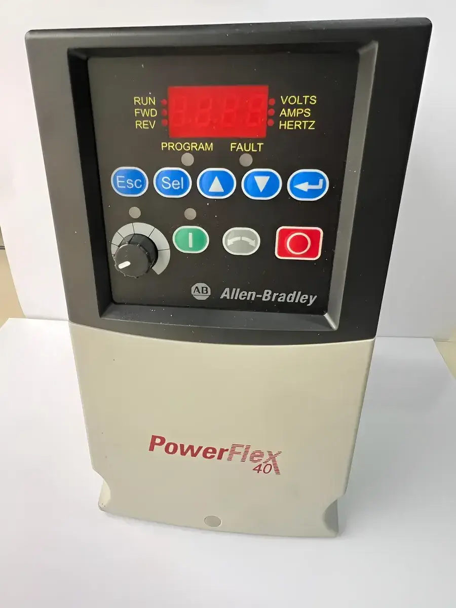

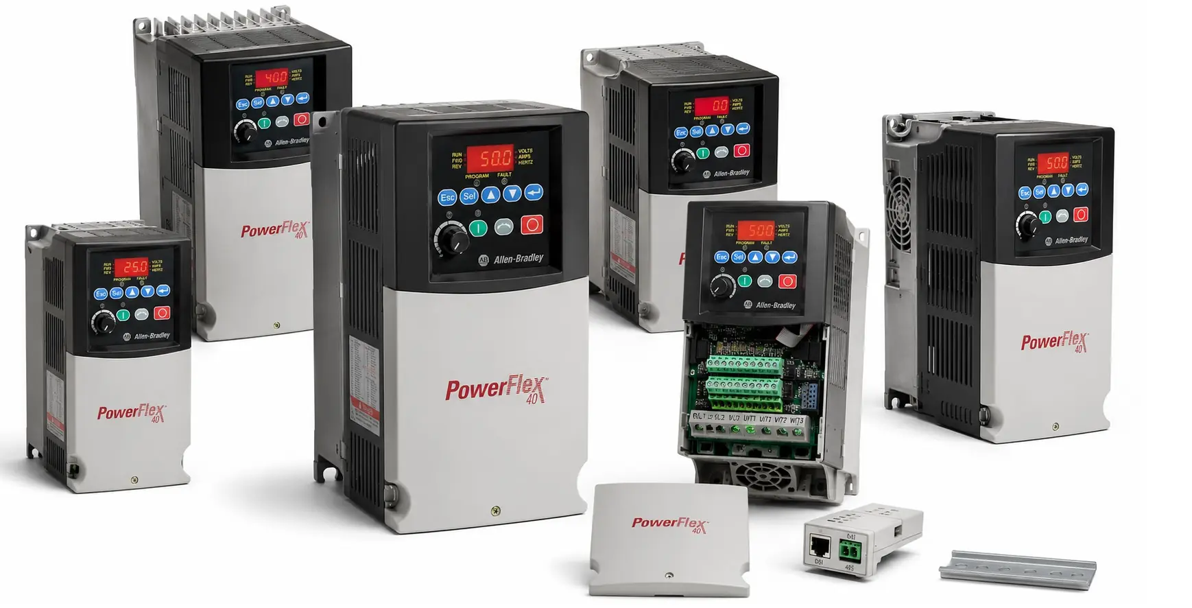
Allen-Bradley Powerflex 40 Specifications
| Category | Specification |
|---|---|
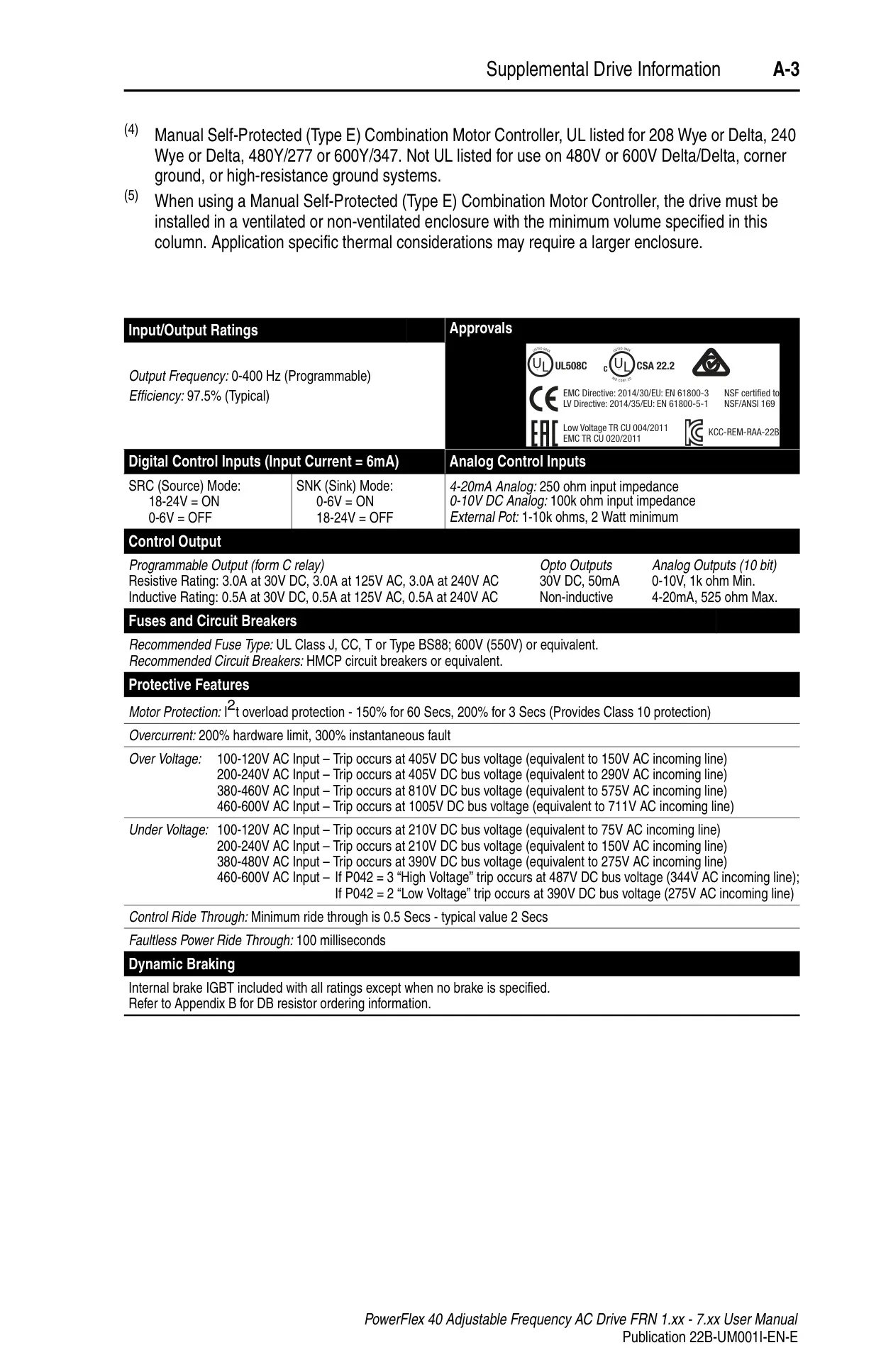
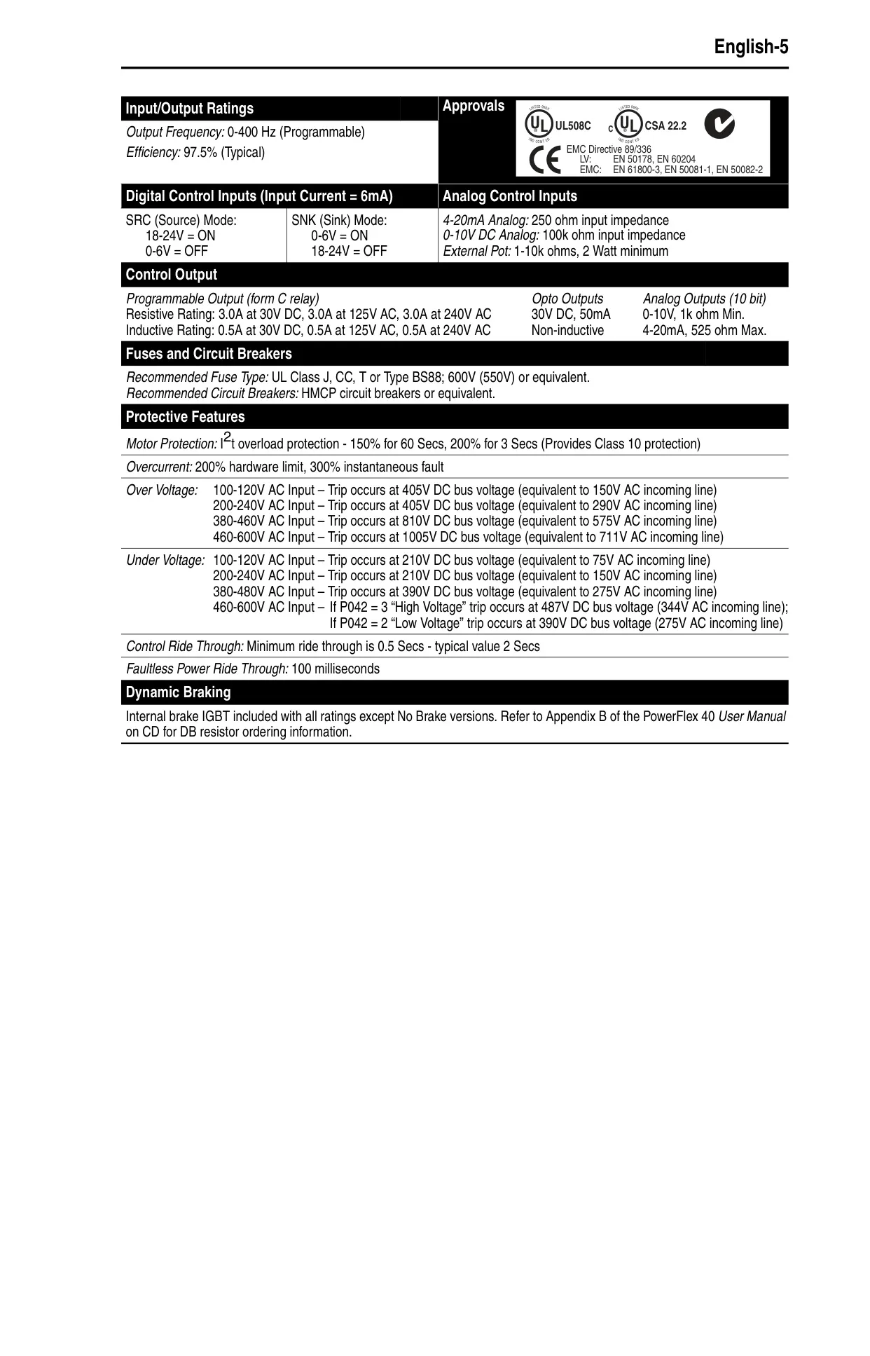
| Output Frequency Range | 0-400 Hz (Programmable) |
| Typical Efficiency | 97.5% |
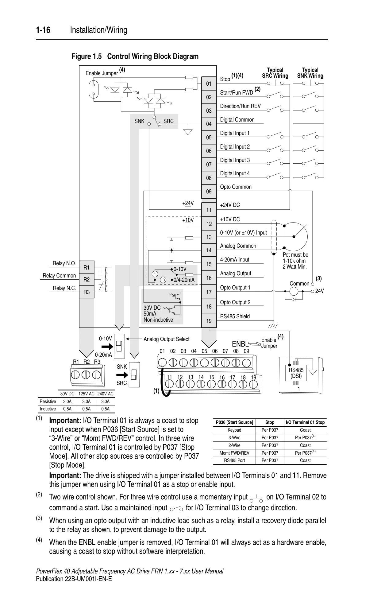
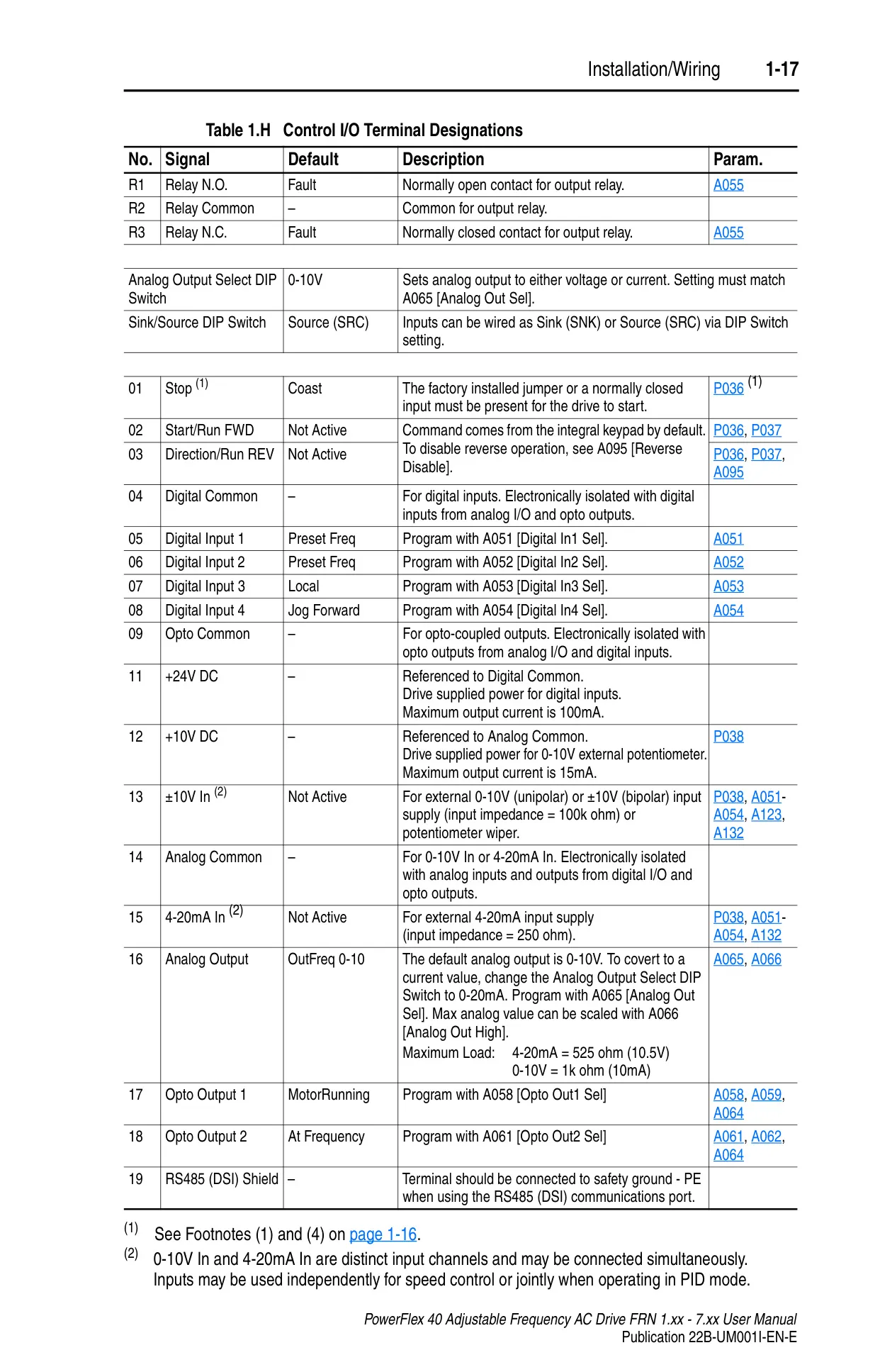
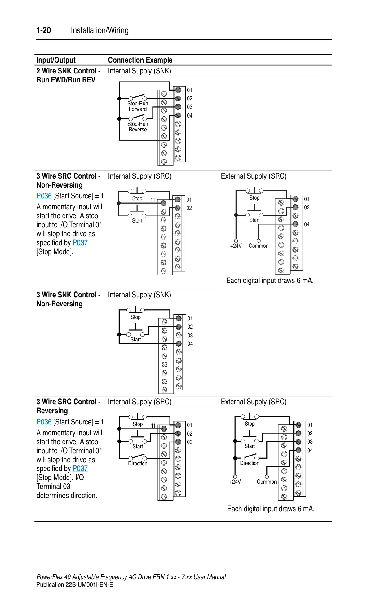
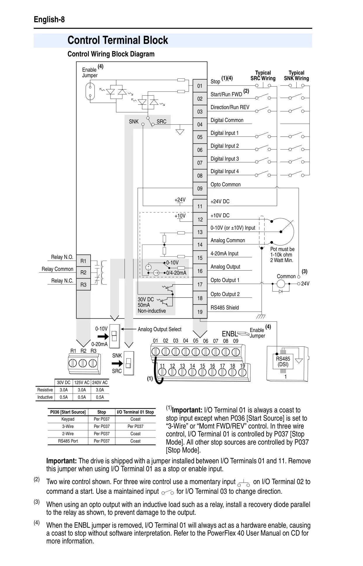
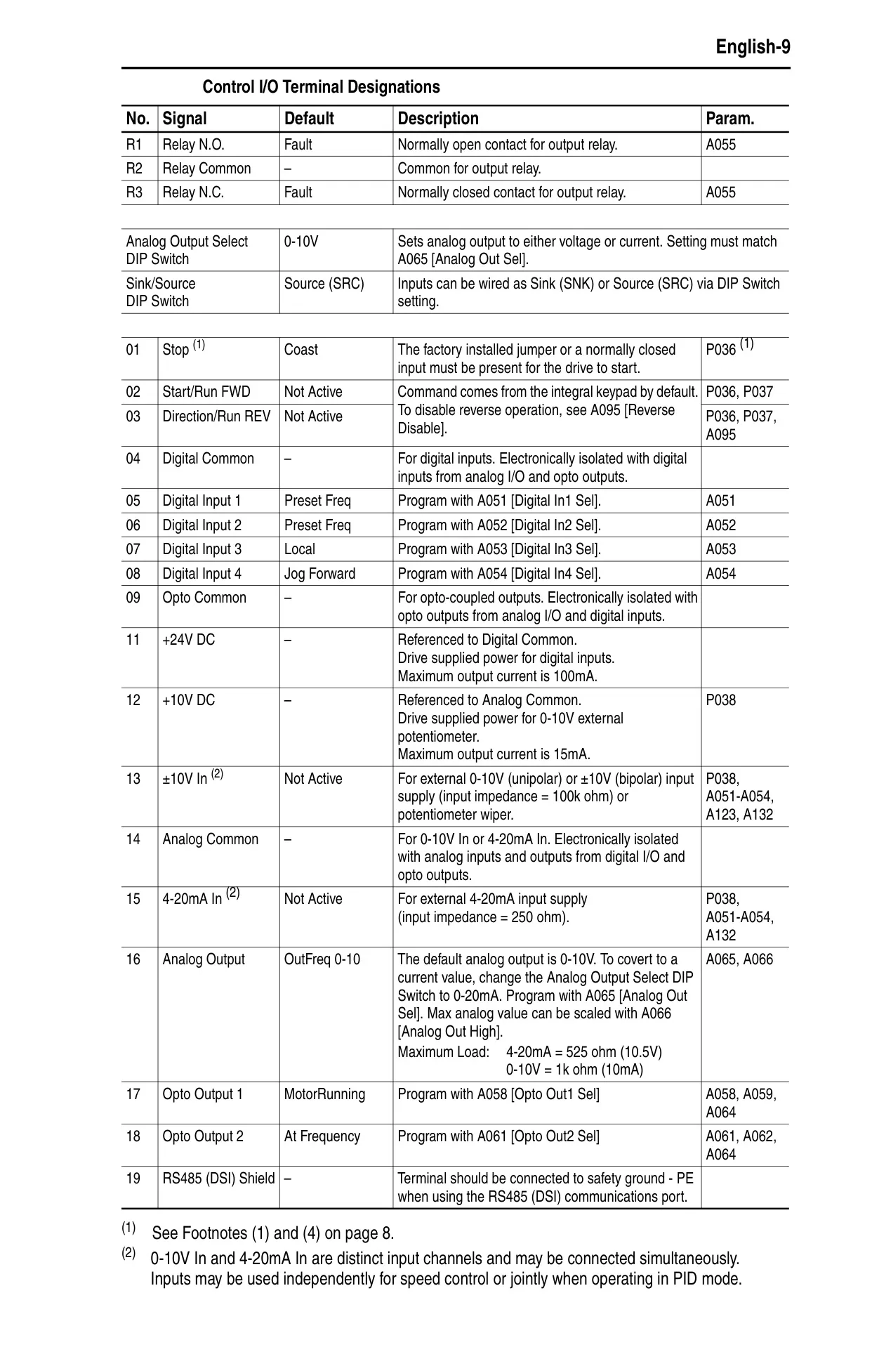
| Digital Control Inputs | 6mA input current; SRC (18-24V ON, 0-6V OFF), SNK (0-6V ON, 18-24V OFF) |
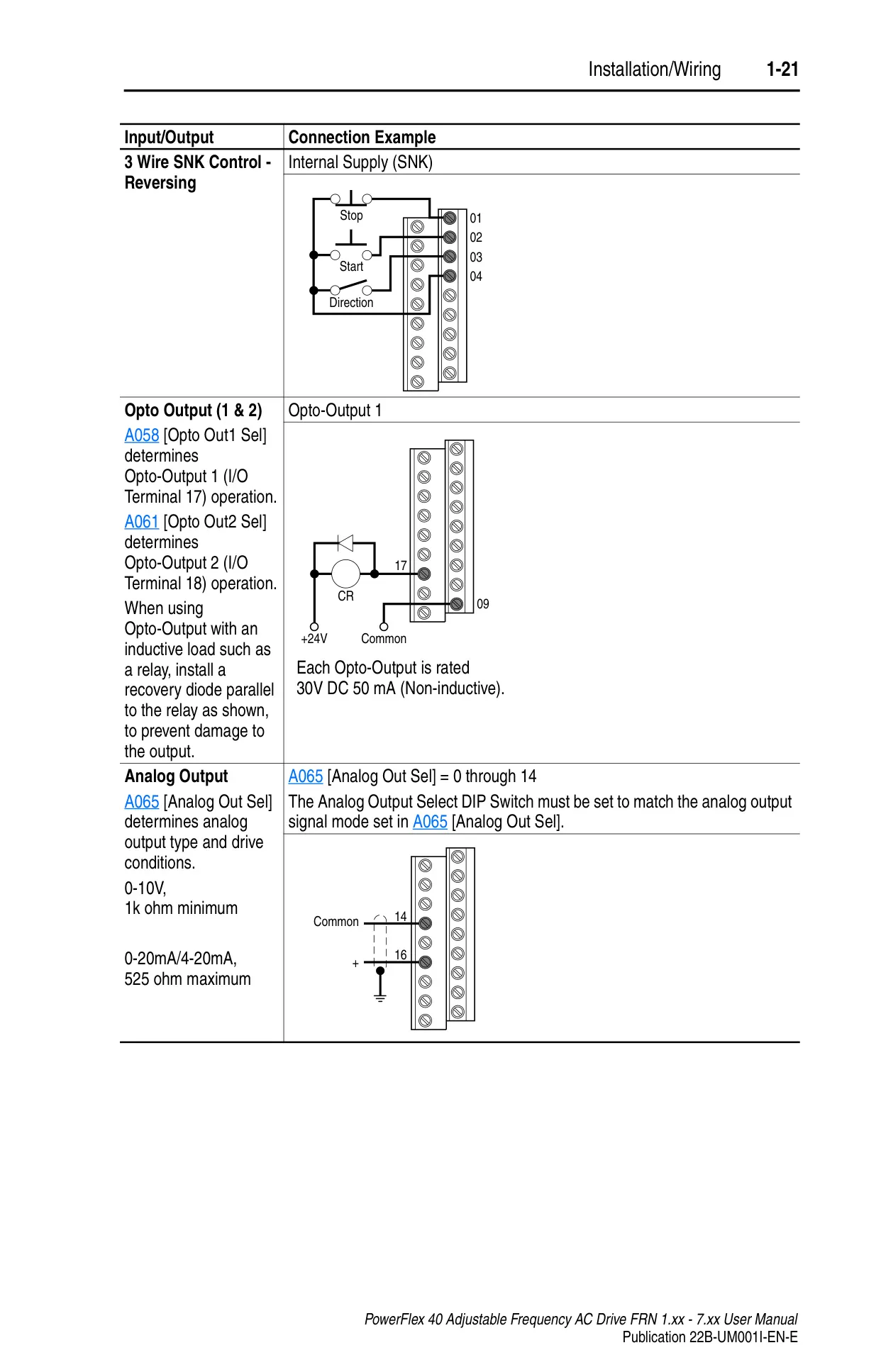
| Analog Control Inputs | 4-20mA (250 Ω), 0-10V DC (100k Ω), External Pot (1-10k Ω, 2W min) |
| Programmable Relay Output (Form C) | Resistive: 3.0A @ 30V DC / 125V AC / 240V AC; Inductive: 0.5A @ 30V DC / 125V AC / 240V AC |
| Opto Outputs | 30V DC, 50mA Non-inductive |
| Analog Outputs | 10-bit resolution; 0-10V (1k Ω Min.), 4-20mA (525 Ω Max.) |
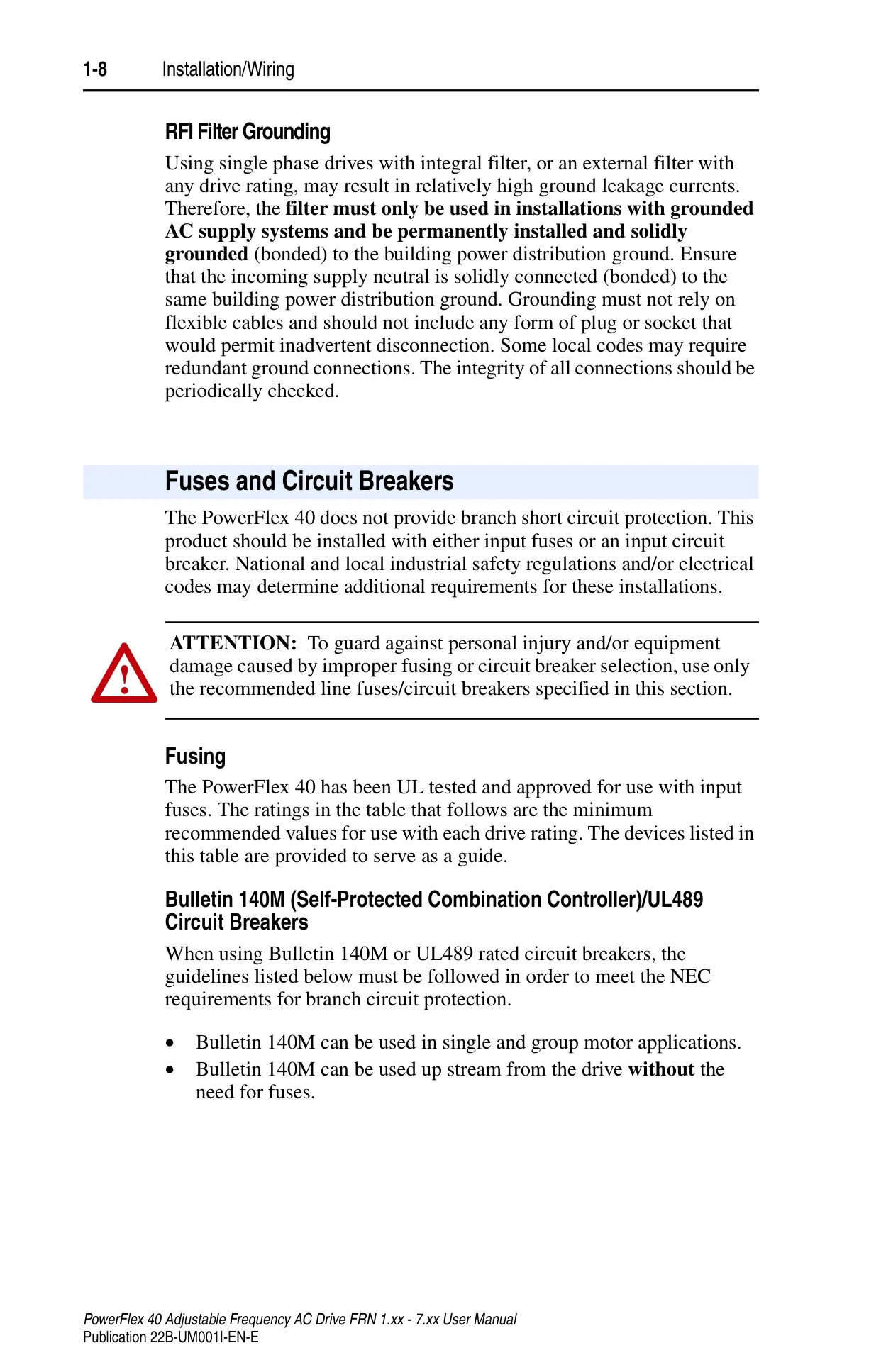
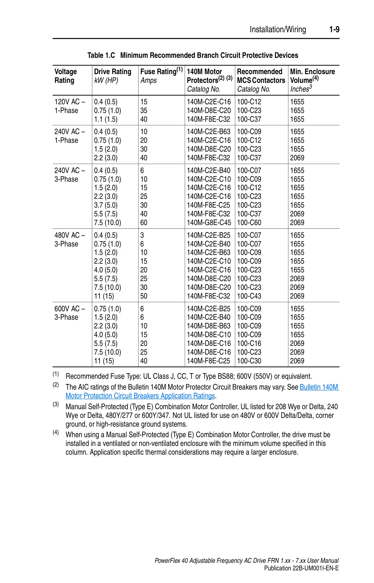
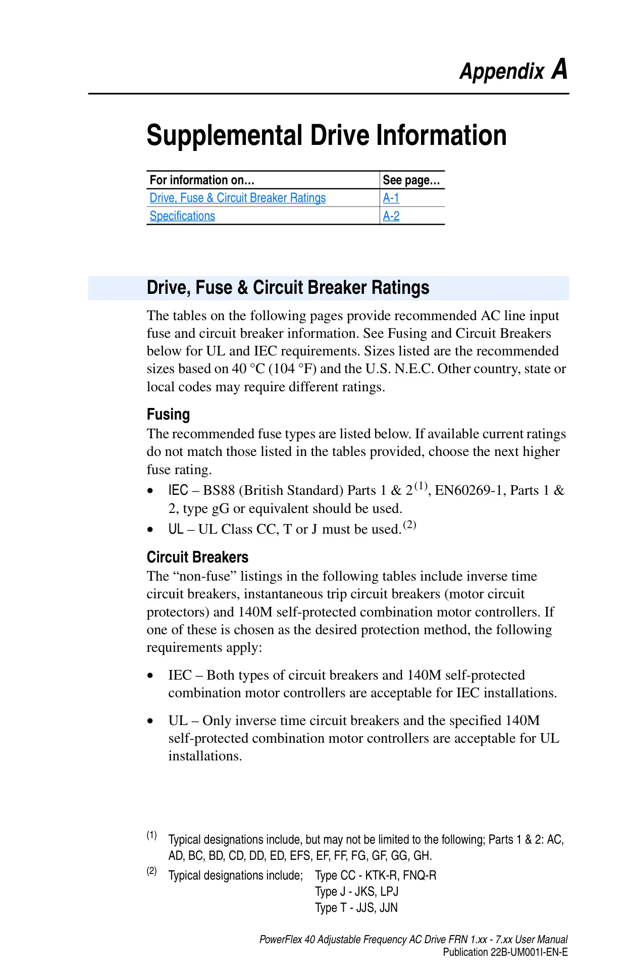
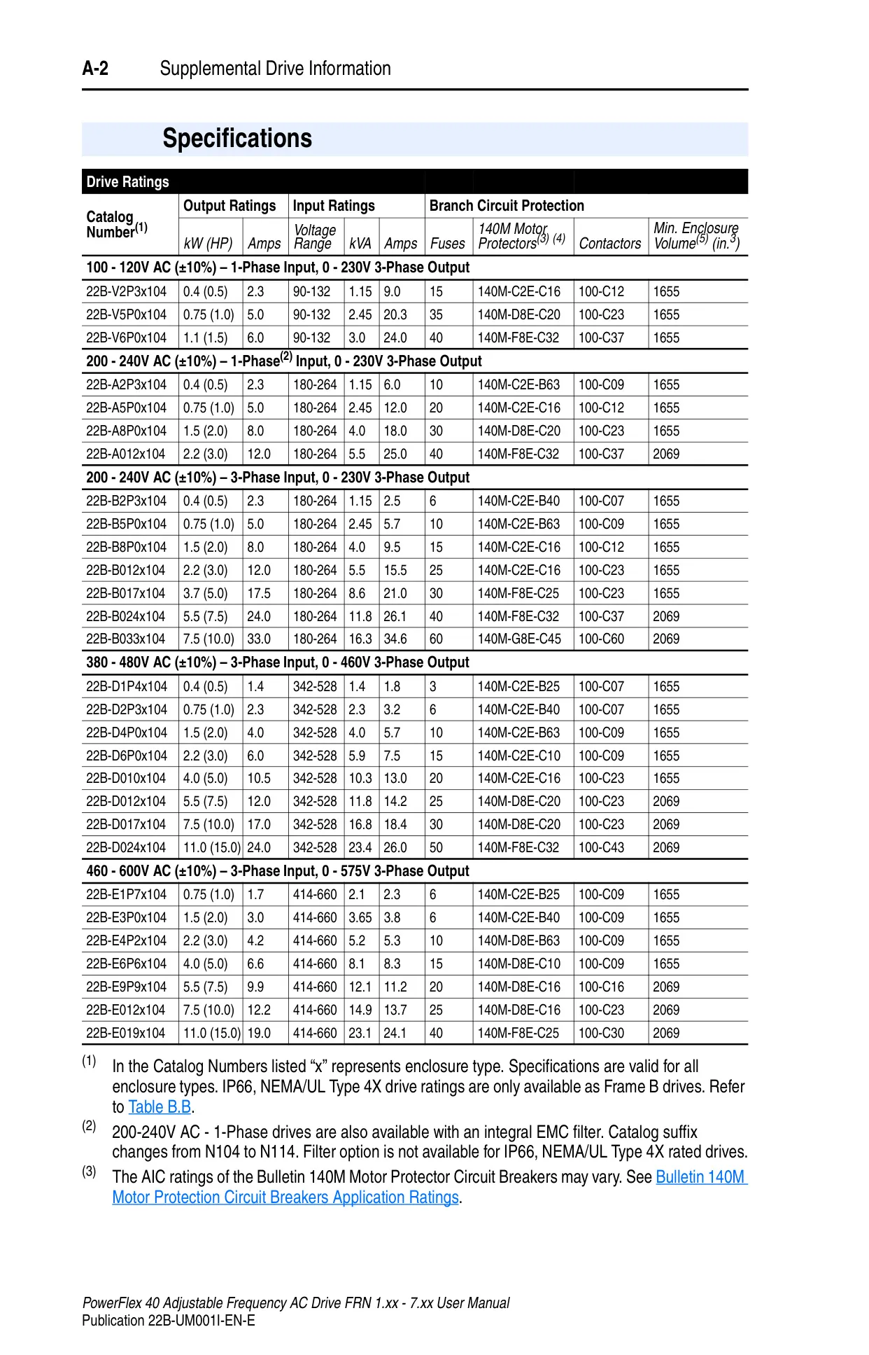
| Recommended Fuses | UL Class J, CC, T or BS88; 600V (550V) or equivalent |
| Recommended Circuit Breakers | HMCP circuit breakers or equivalent |
| Motor Overload Protection | I²t overload, 150% for 60s, 200% for 3s (Class 10) |
| Overcurrent Protection | 200% hardware limit, 300% instantaneous fault |
| Control Ride Through | Min. 0.5s, typical 2s |
| Faultless Power Ride Through | 100ms |
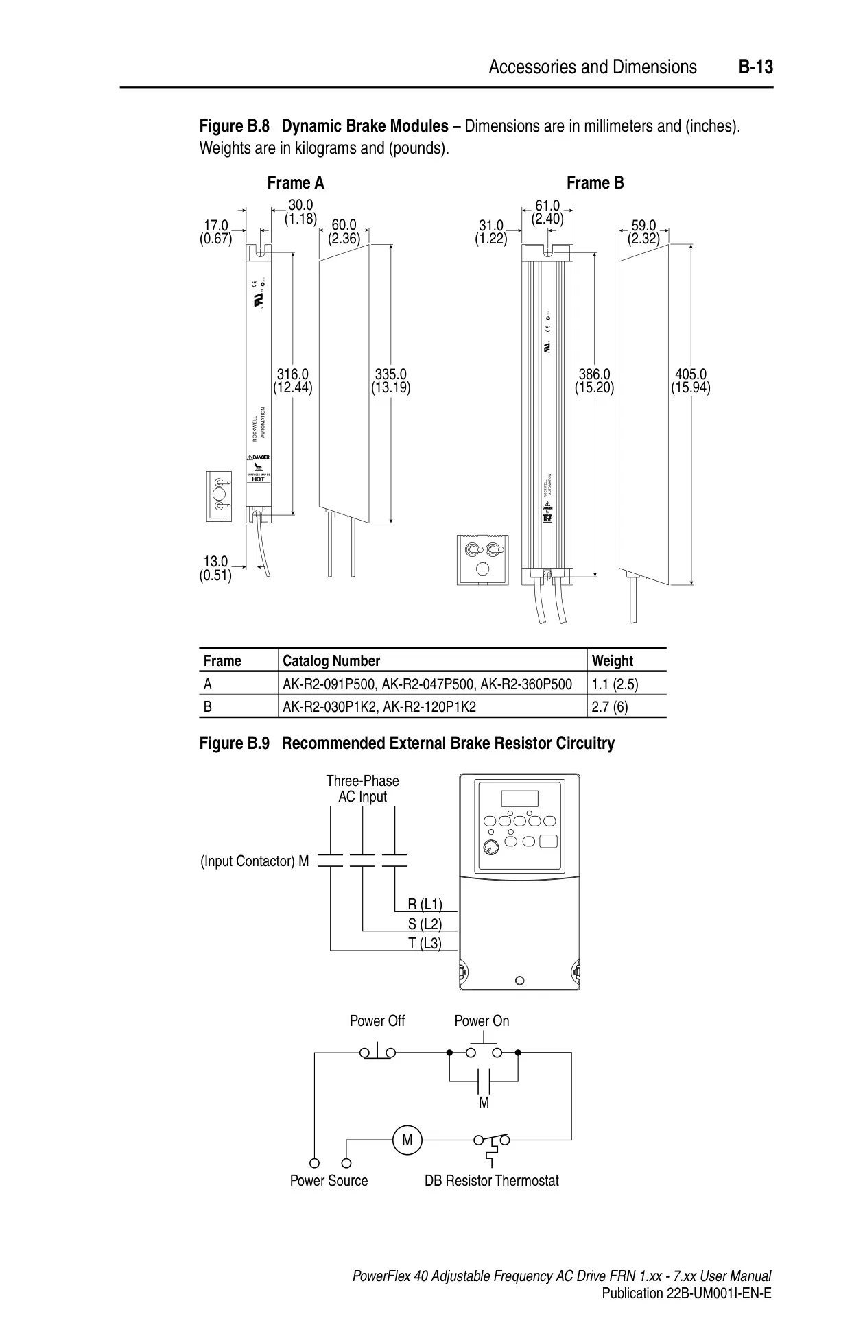
| Dynamic Braking | Internal brake IGBT included (unless specified otherwise) |
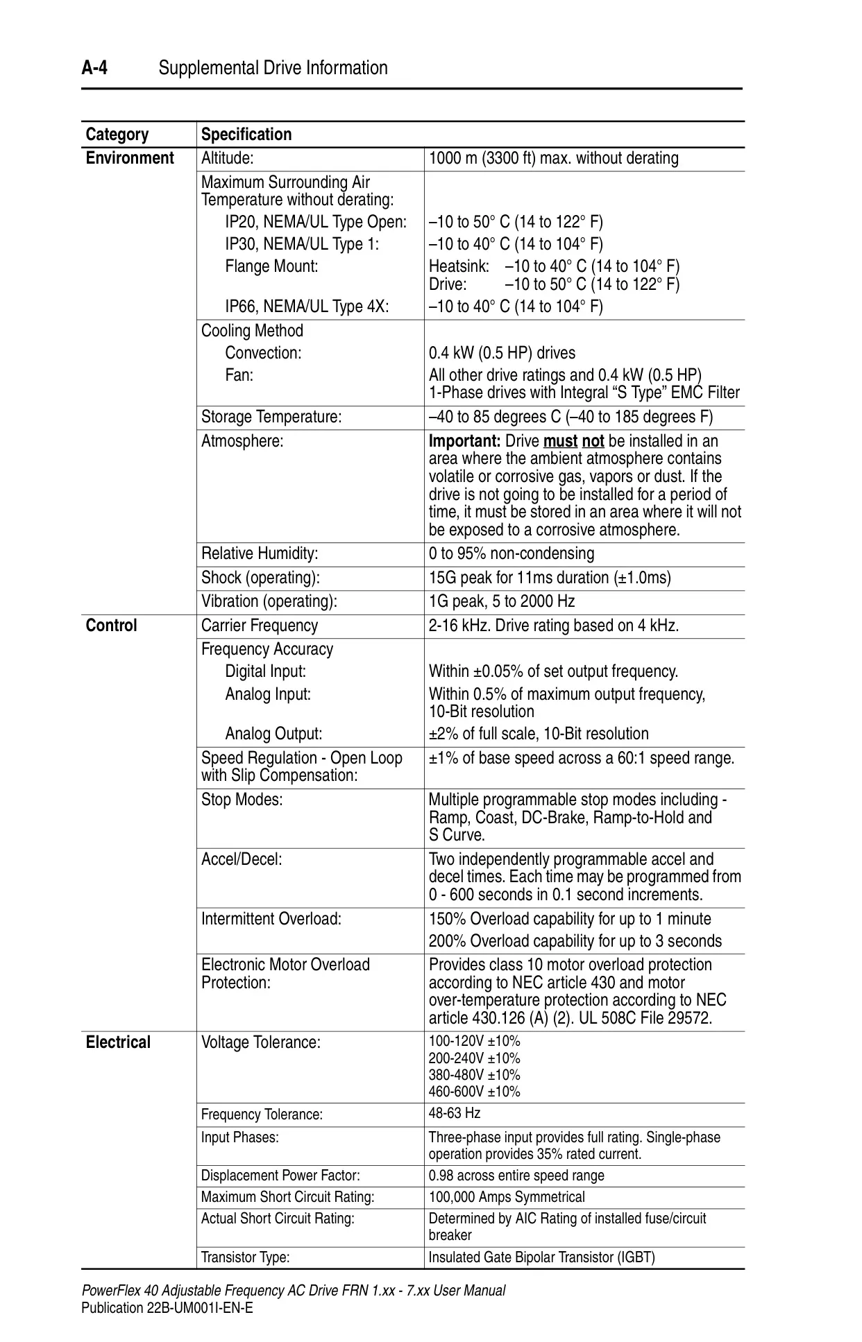
| Maximum Altitude (without derating) | 1000 m (3300 ft) |
| Operating Temperature (IP20 Open) | -10 to 50°C (14 to 122°F) |
| Storage Temperature | -40 to 85°C (-40 to 185°F) |
| Relative Humidity | 0 to 95% non-condensing |
| Operating Shock | 15G peak for 11ms |
| Operating Vibration | 1G peak, 5 to 2000 Hz |
| Carrier Frequency | 2-16 kHz (Drive rating based on 4 kHz) |
| Speed Regulation (Open Loop w/ Slip Comp) | ±1% of base speed (60:1 range) |
| Input Phases | Three-phase (full rating), Single-phase (35% rated current) |
| Displacement Power Factor | 0.98 across entire speed range |
| Maximum Short Circuit Rating | 100,000 Amps Symmetrical |
| Transistor Type | Insulated Gate Bipolar Transistor (IGBT) |
Allen-Bradley Powerflex 40 VFD Details
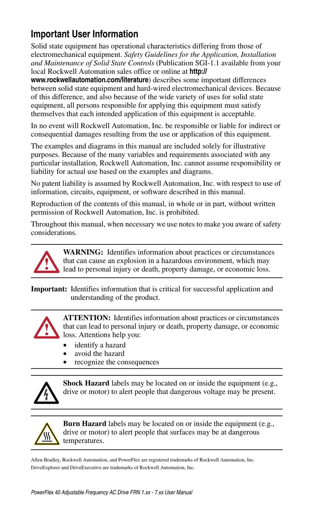
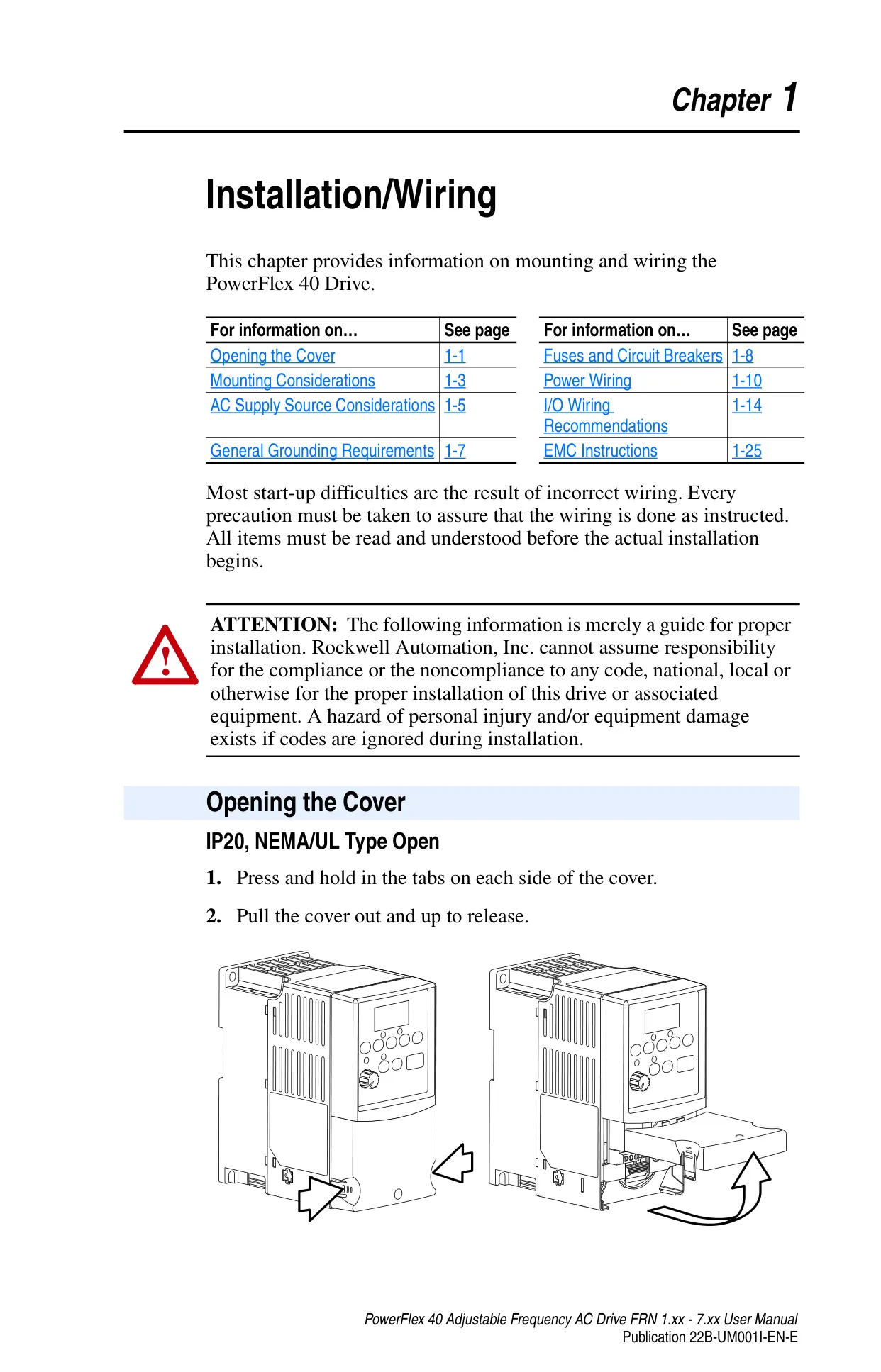
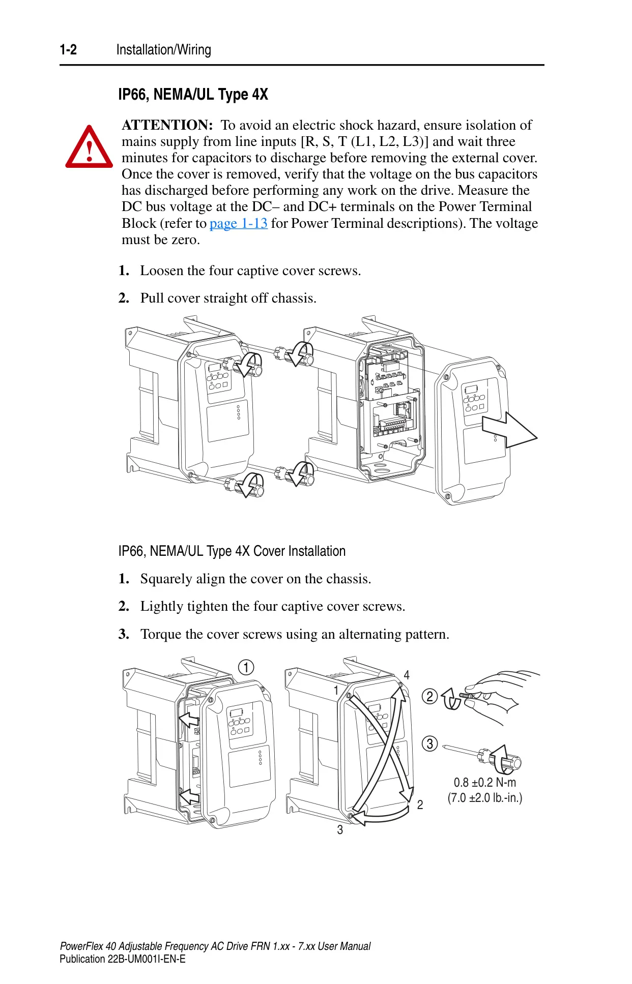
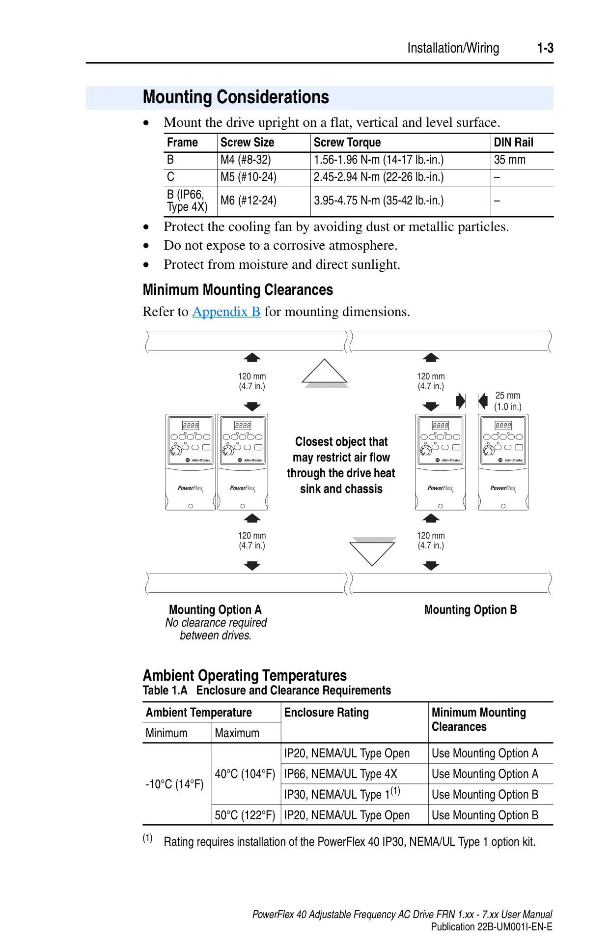
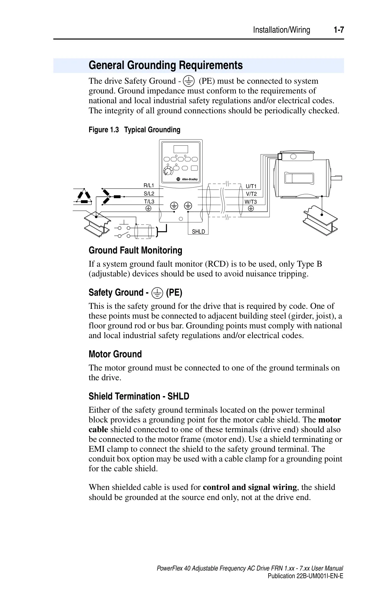
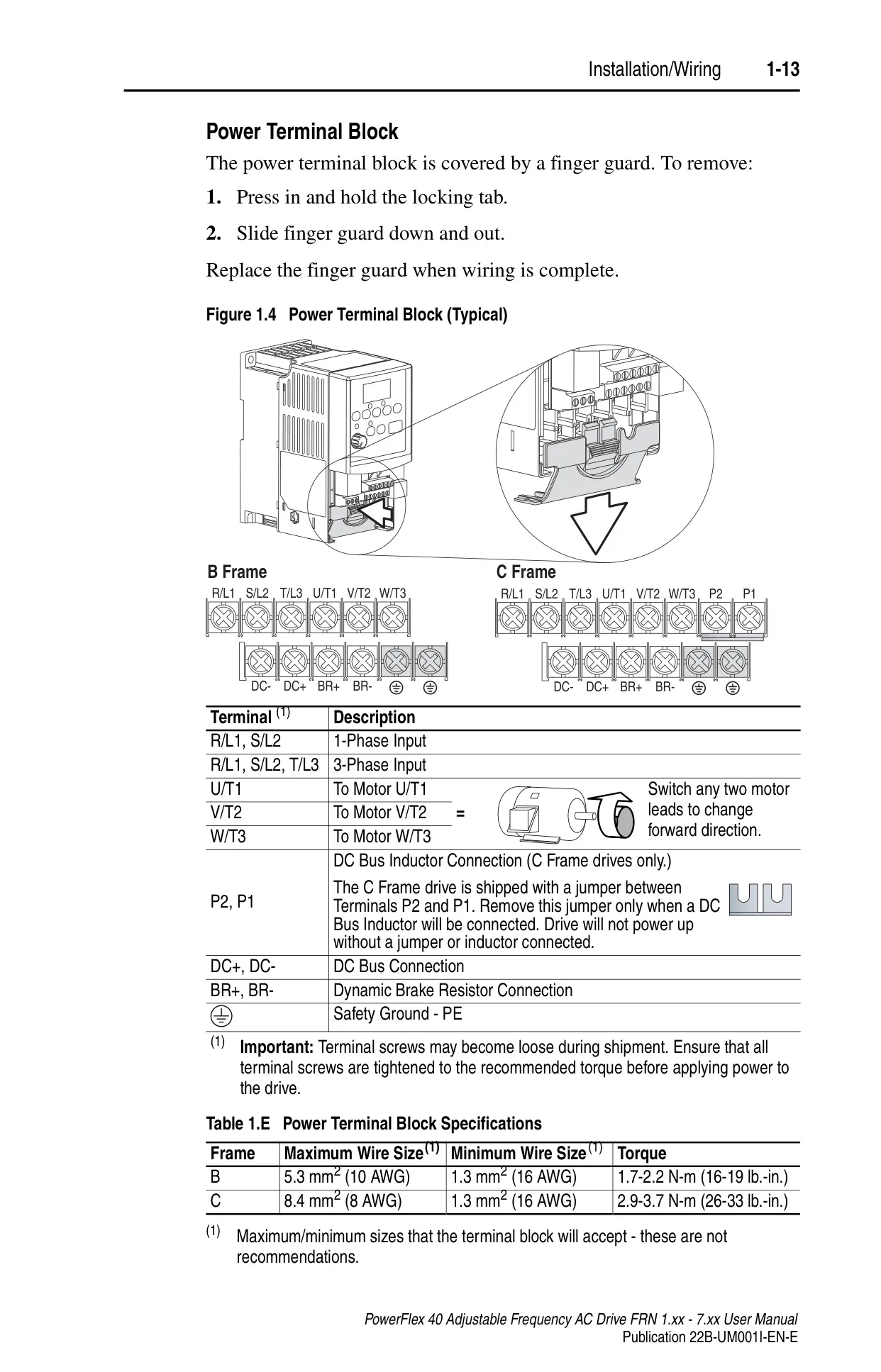
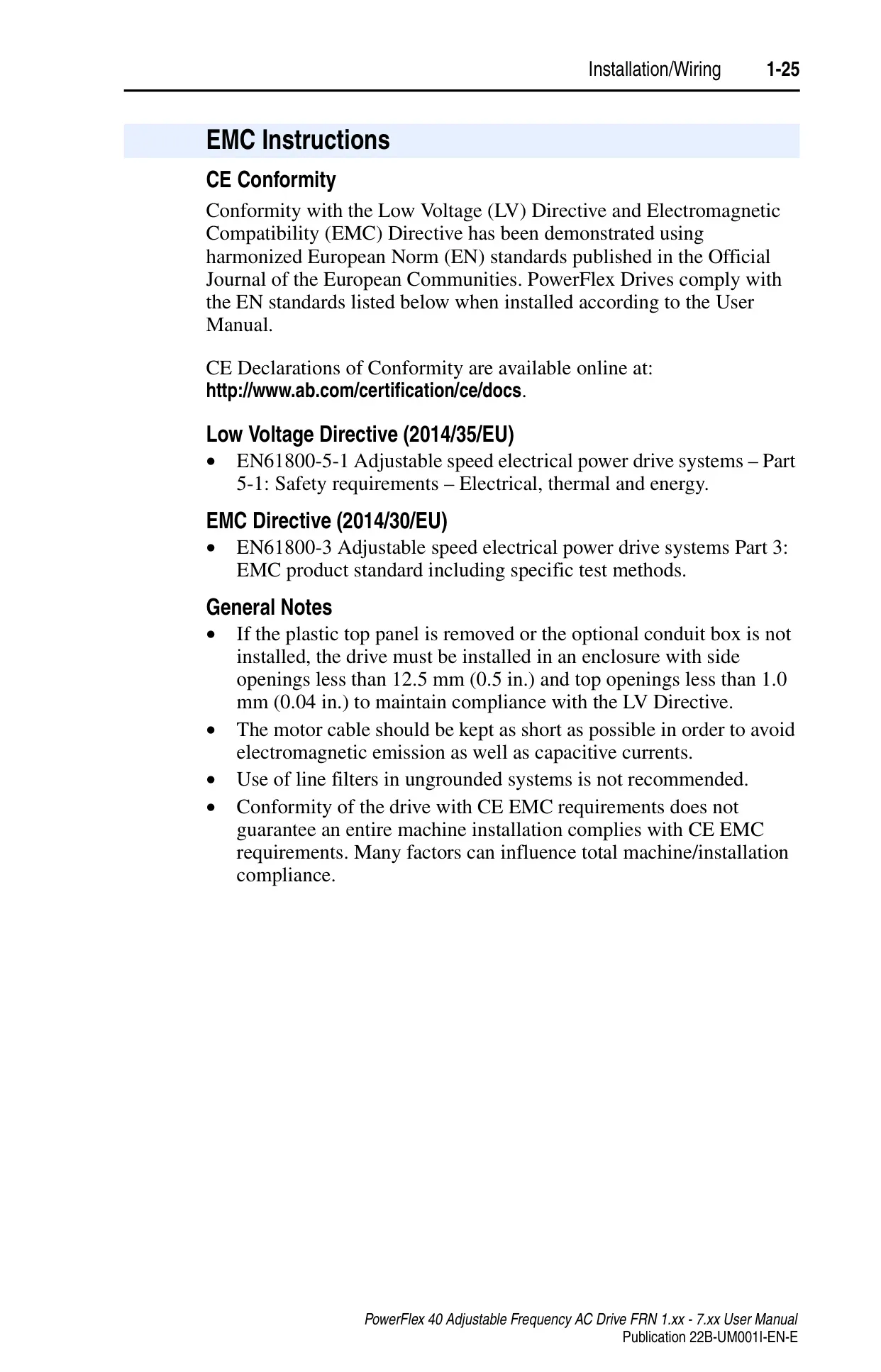
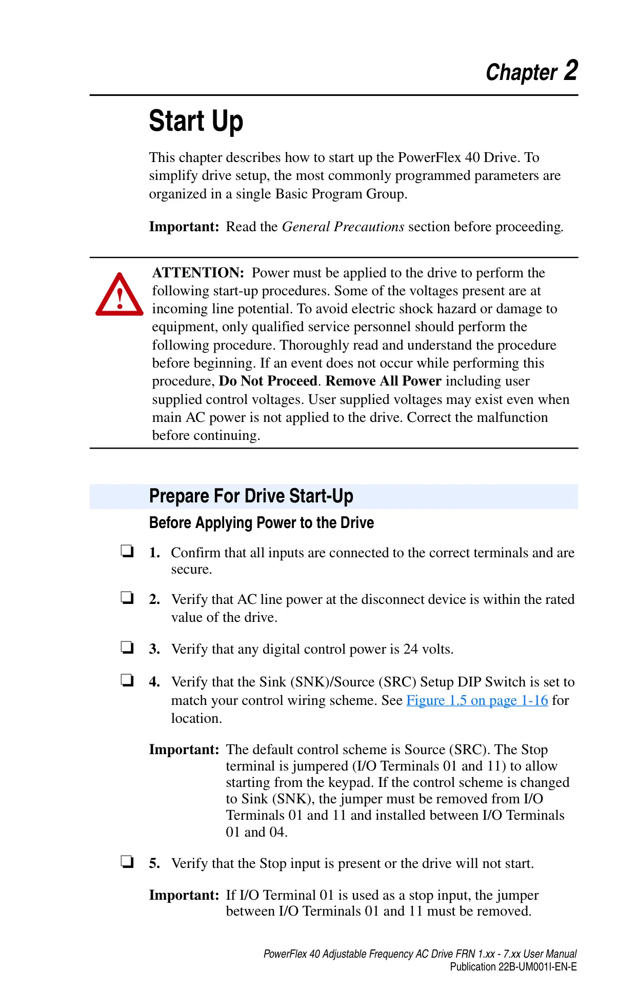
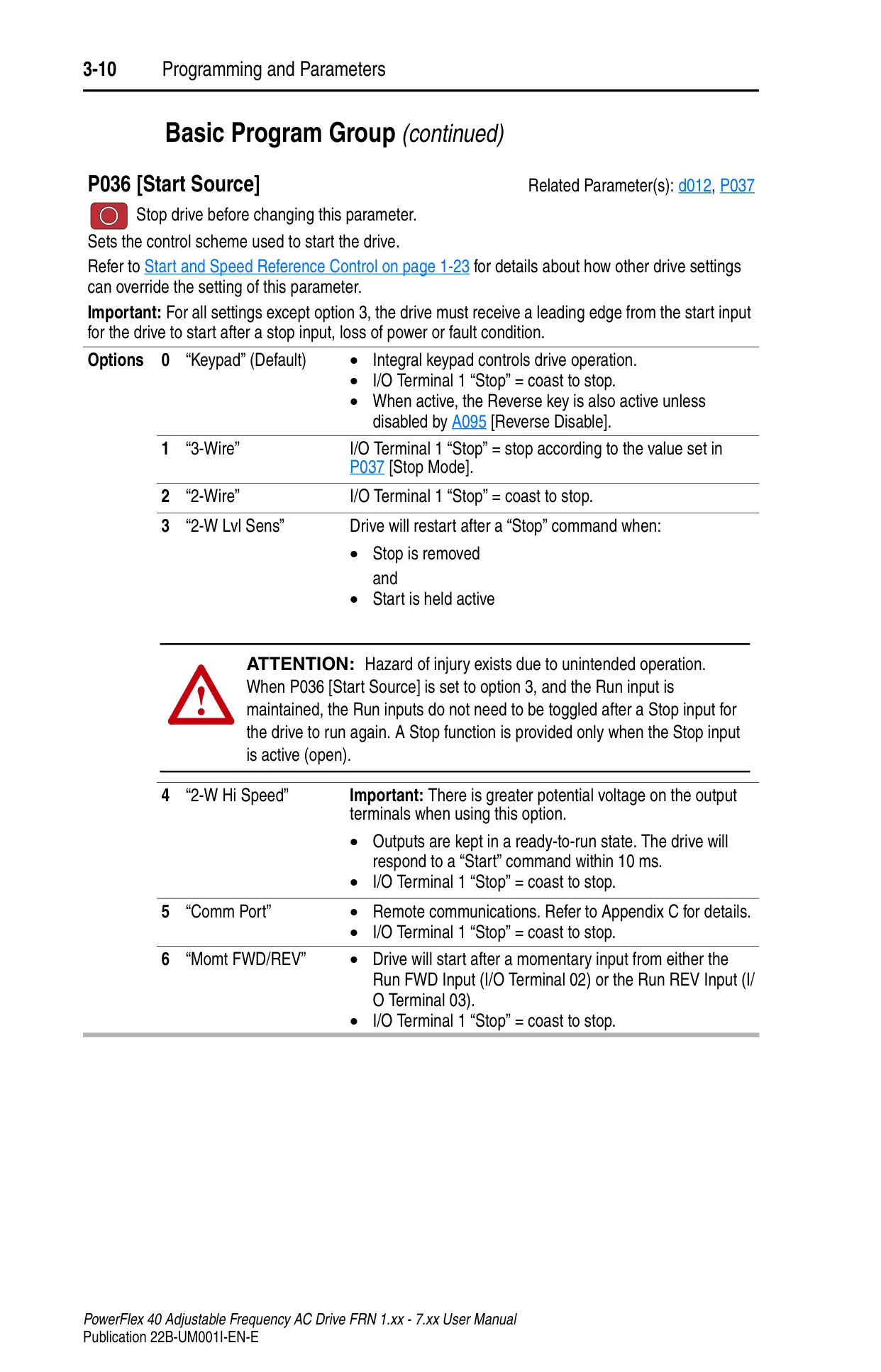
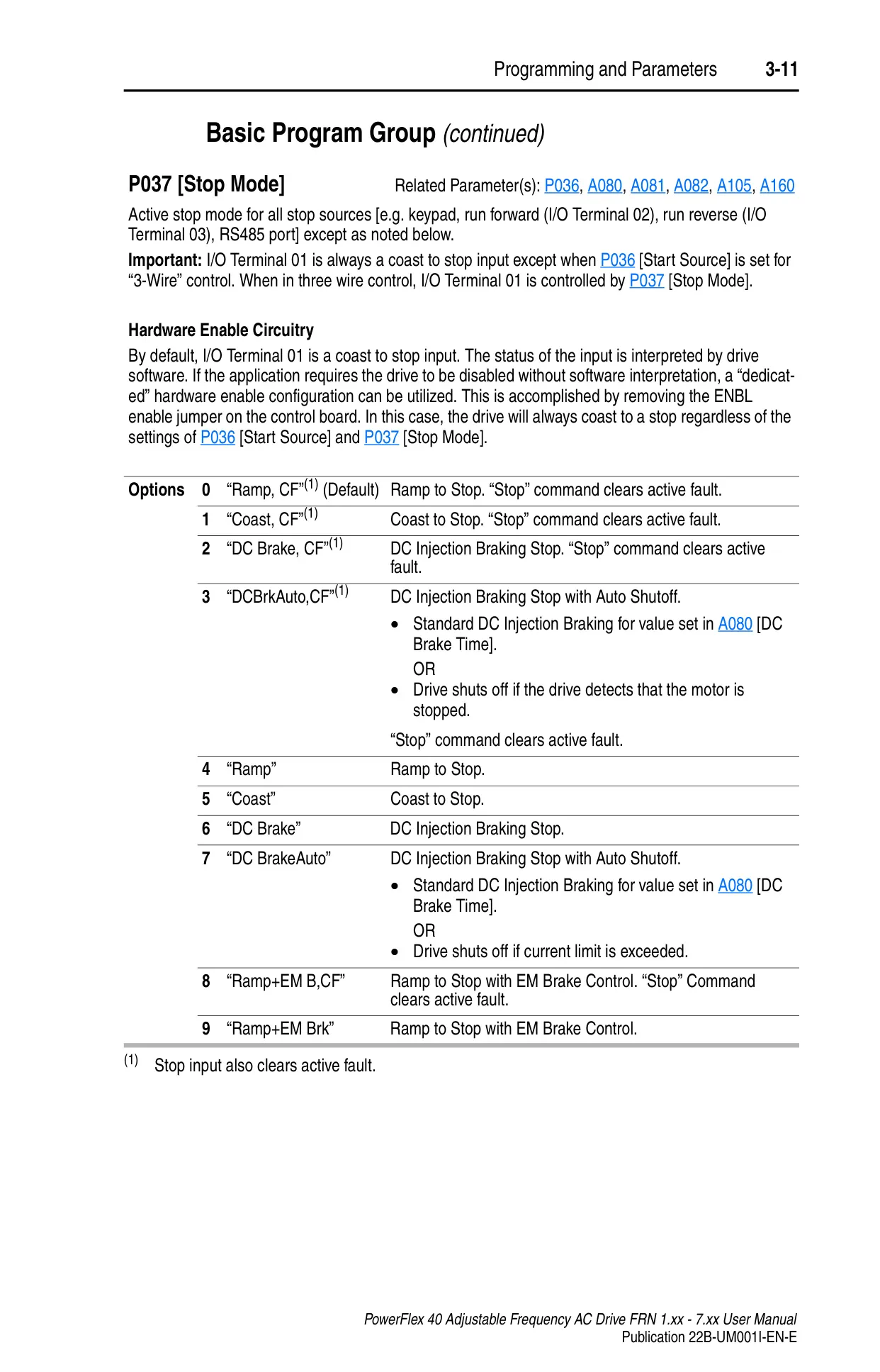
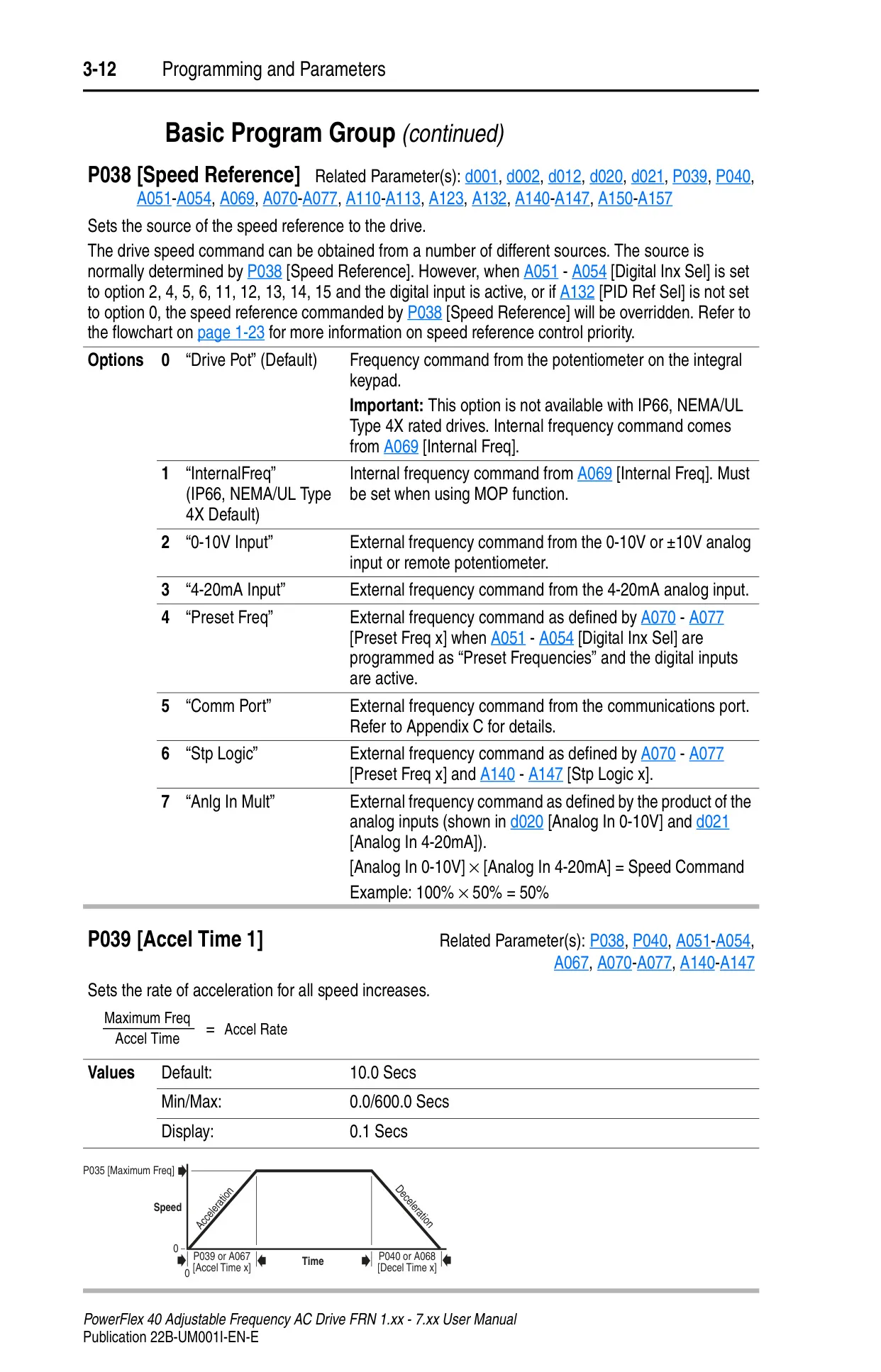
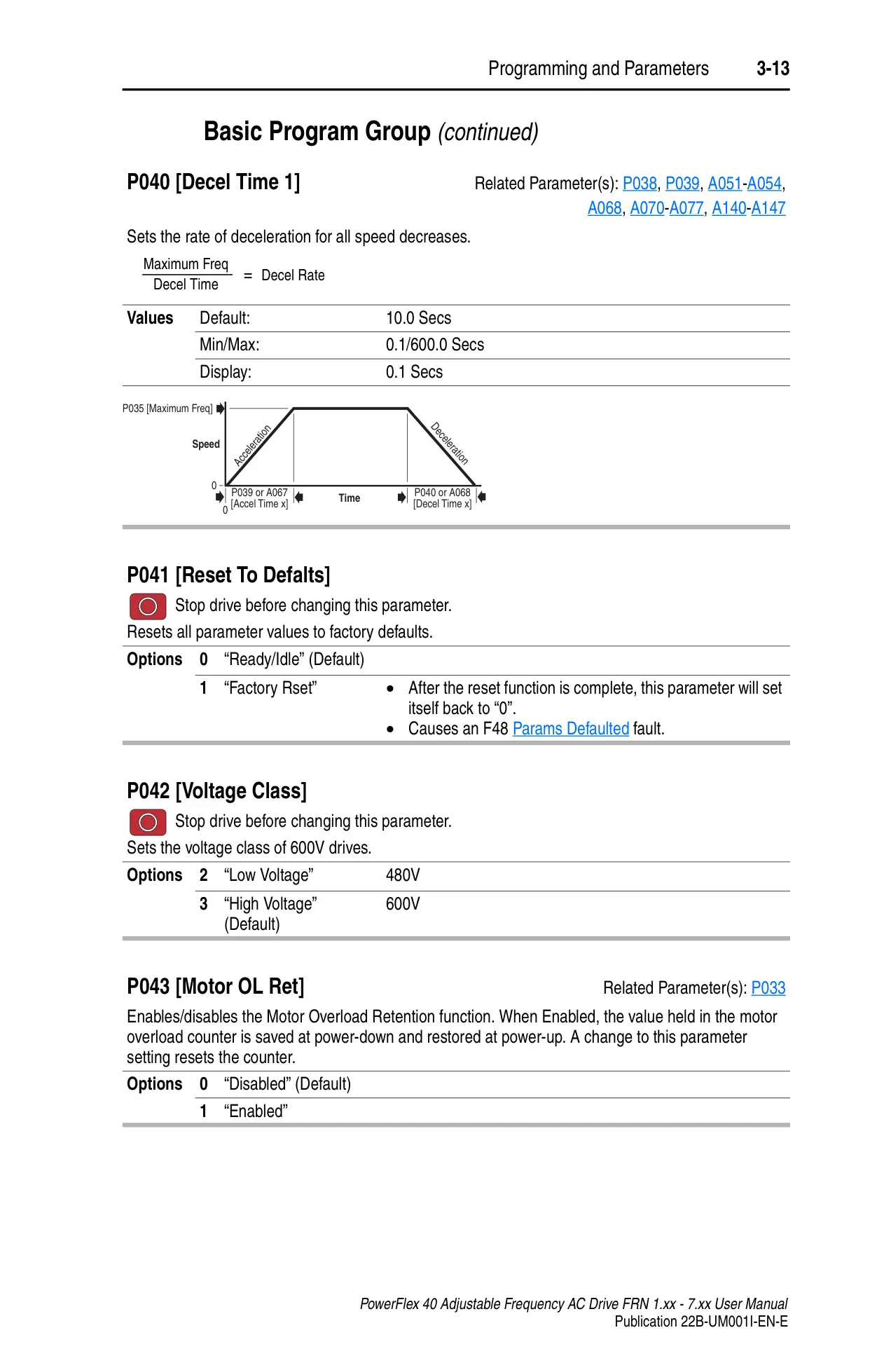
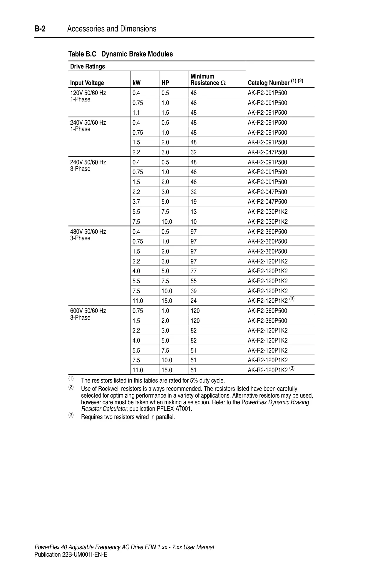
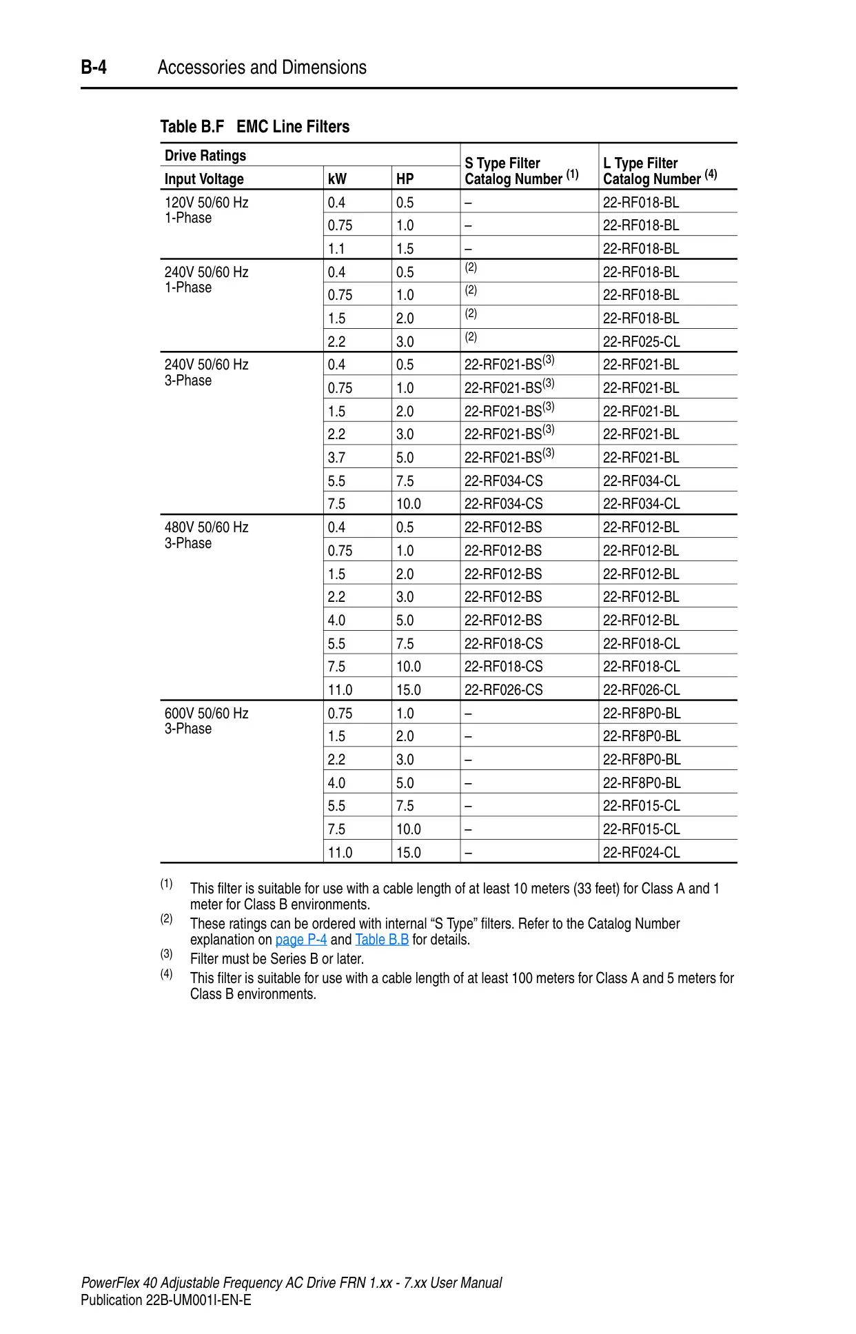
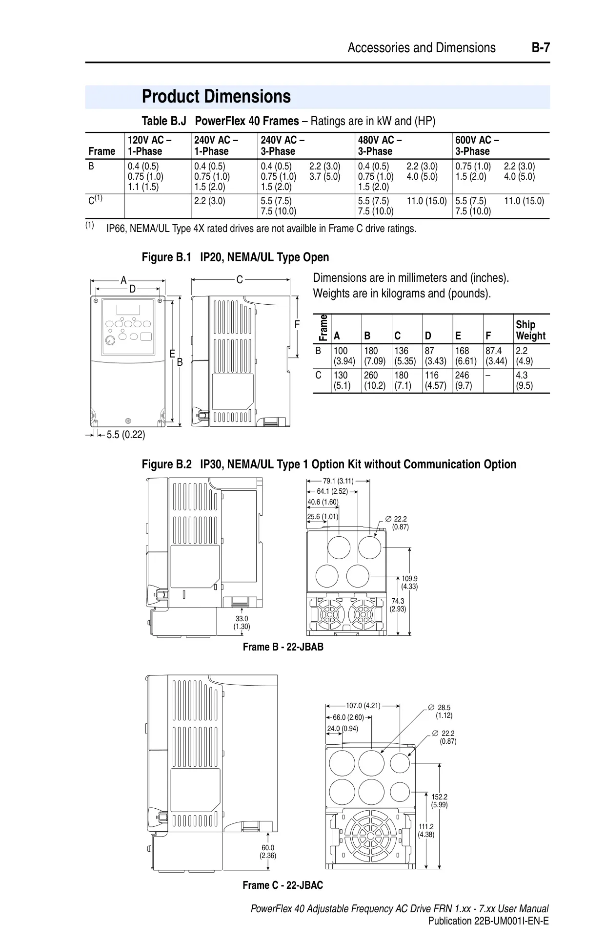
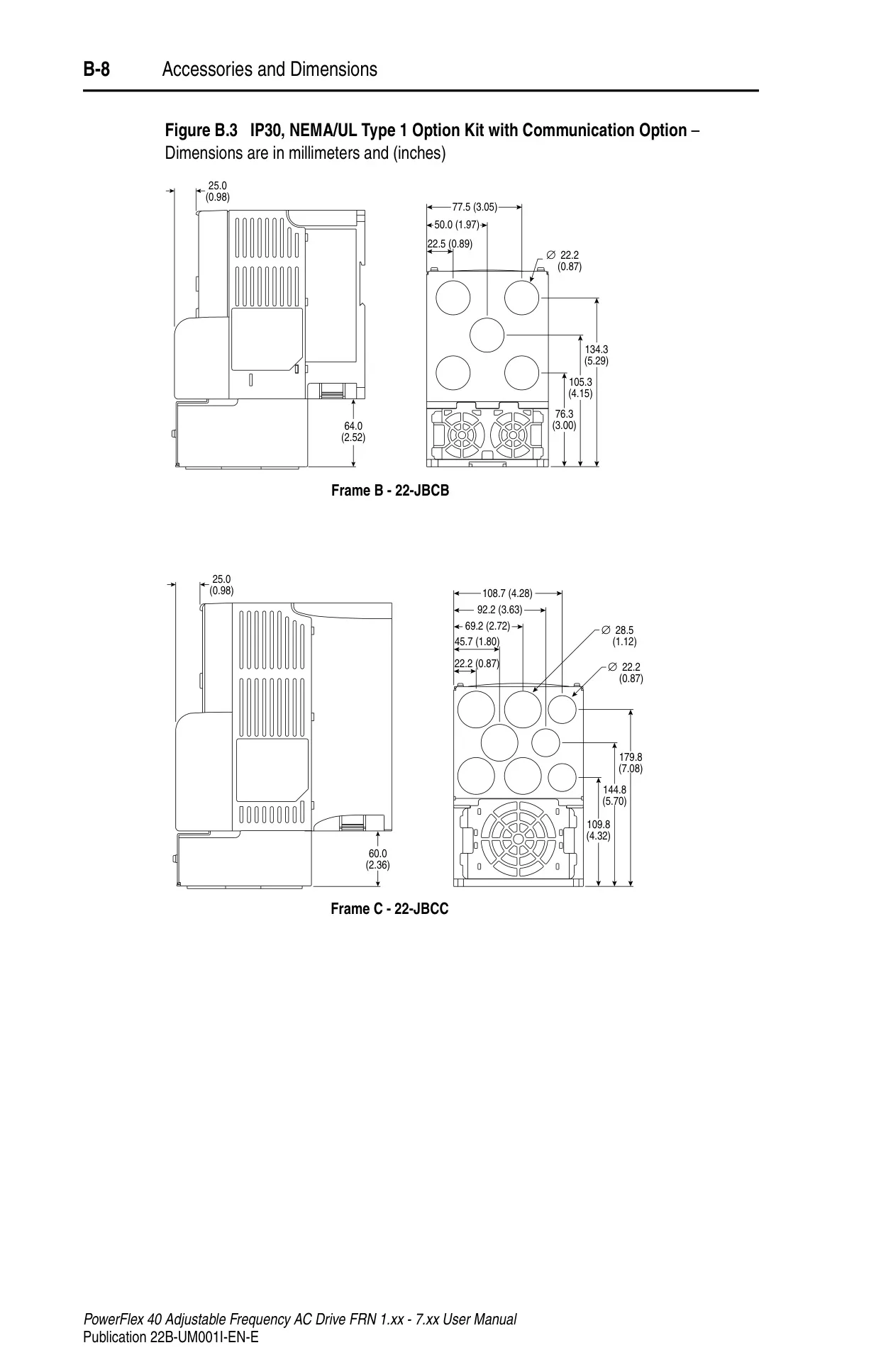
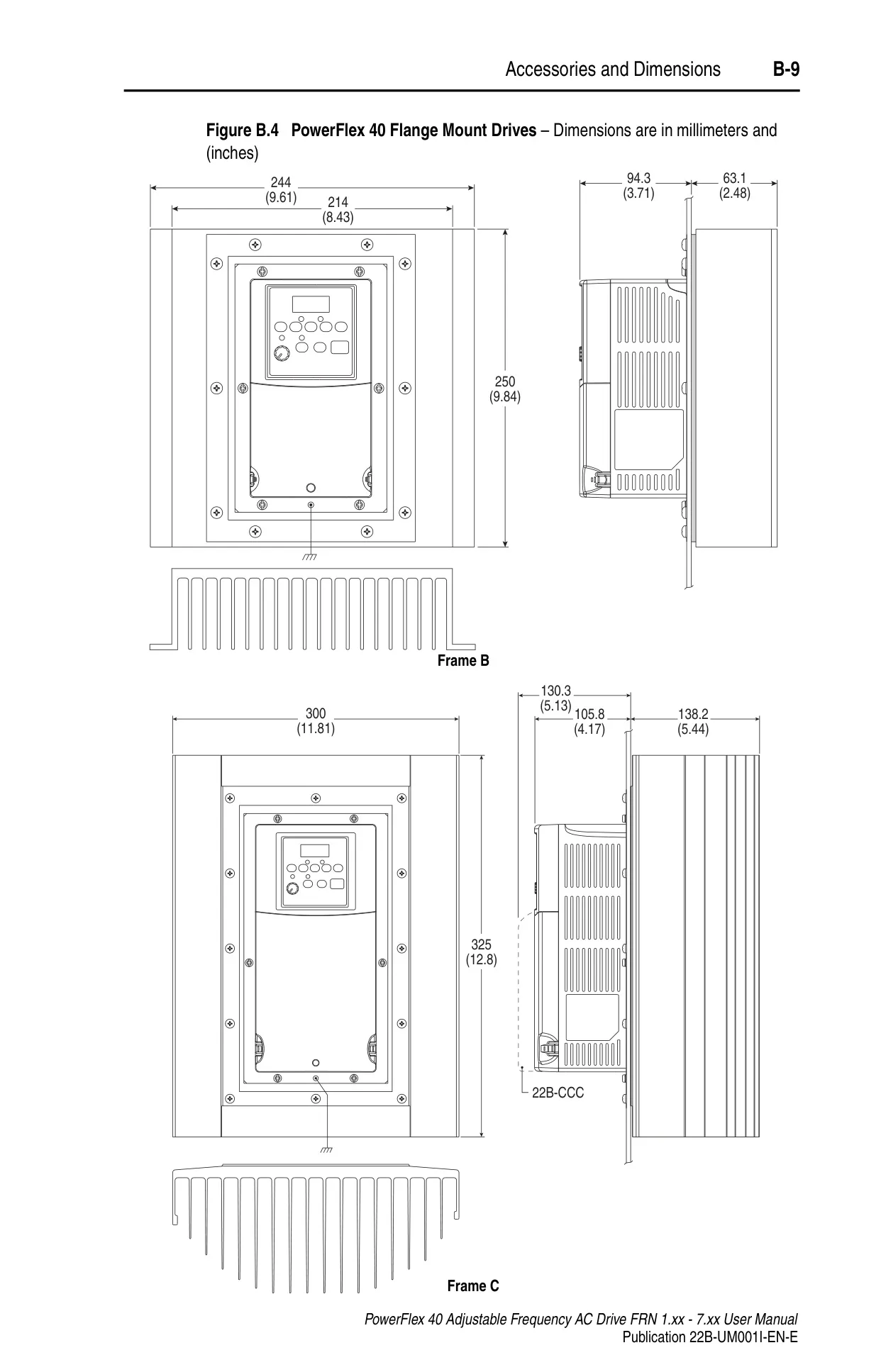
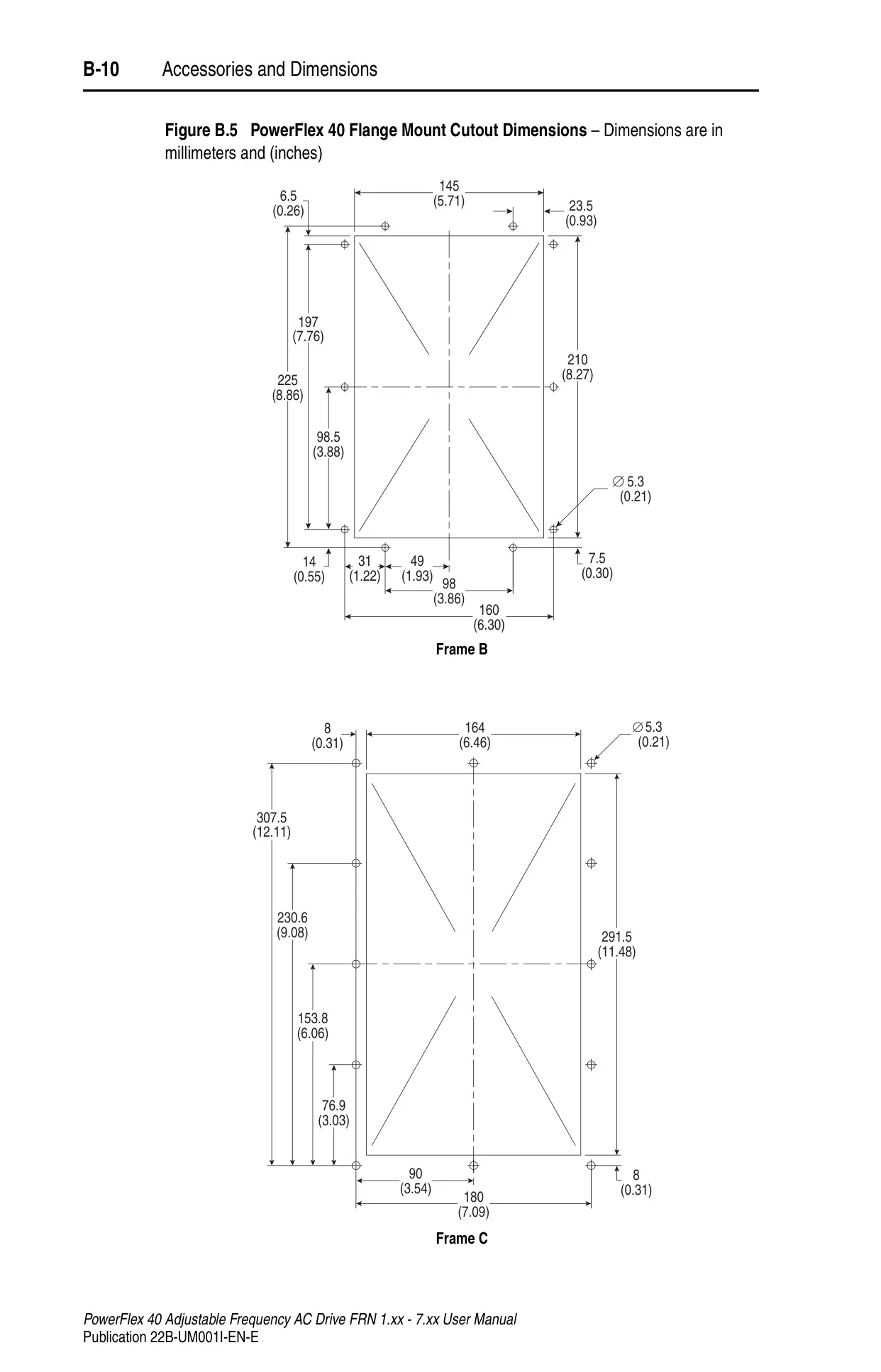
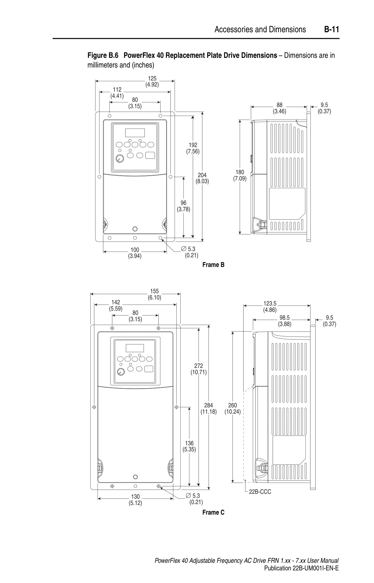
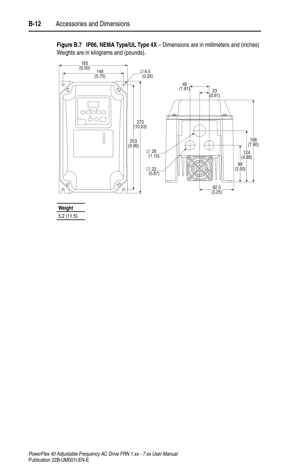
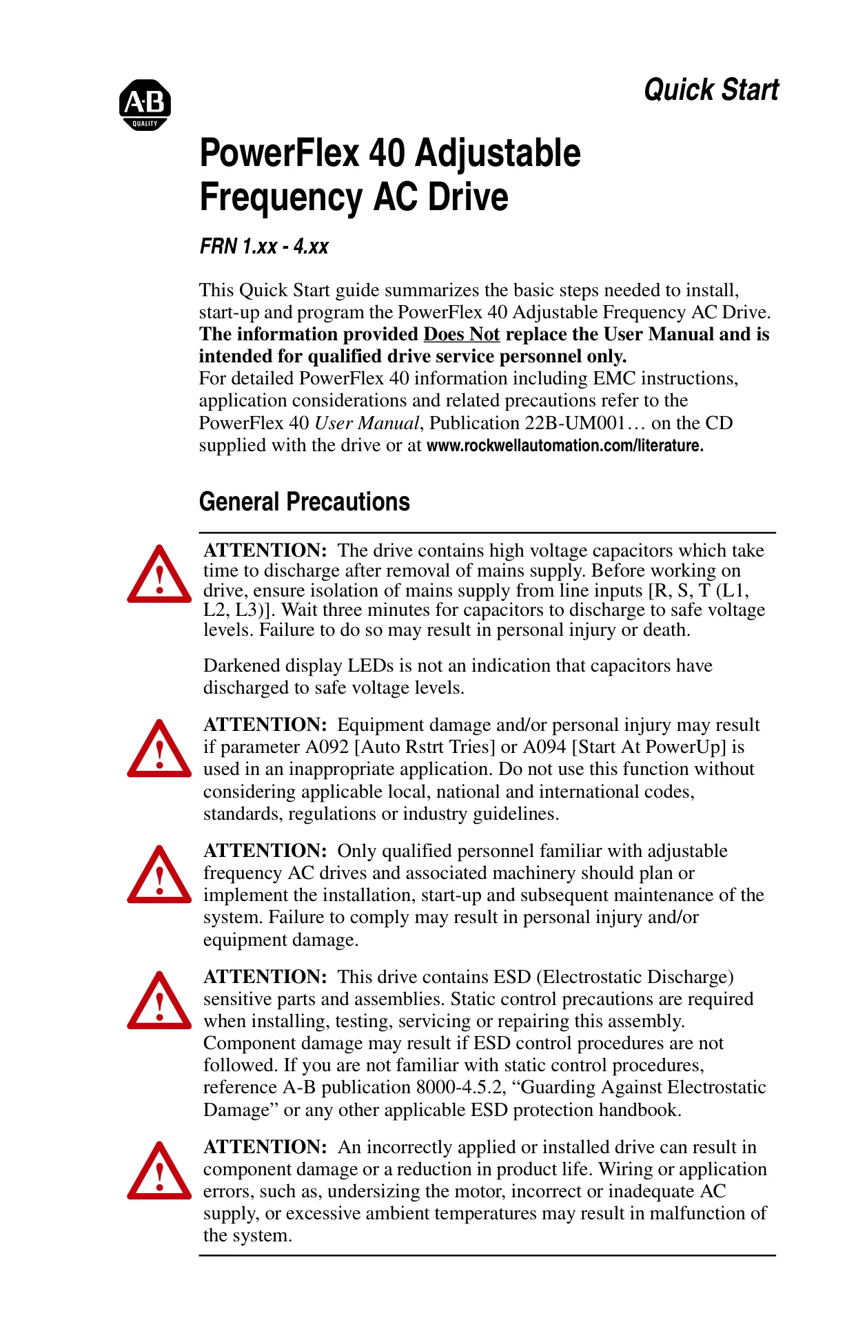
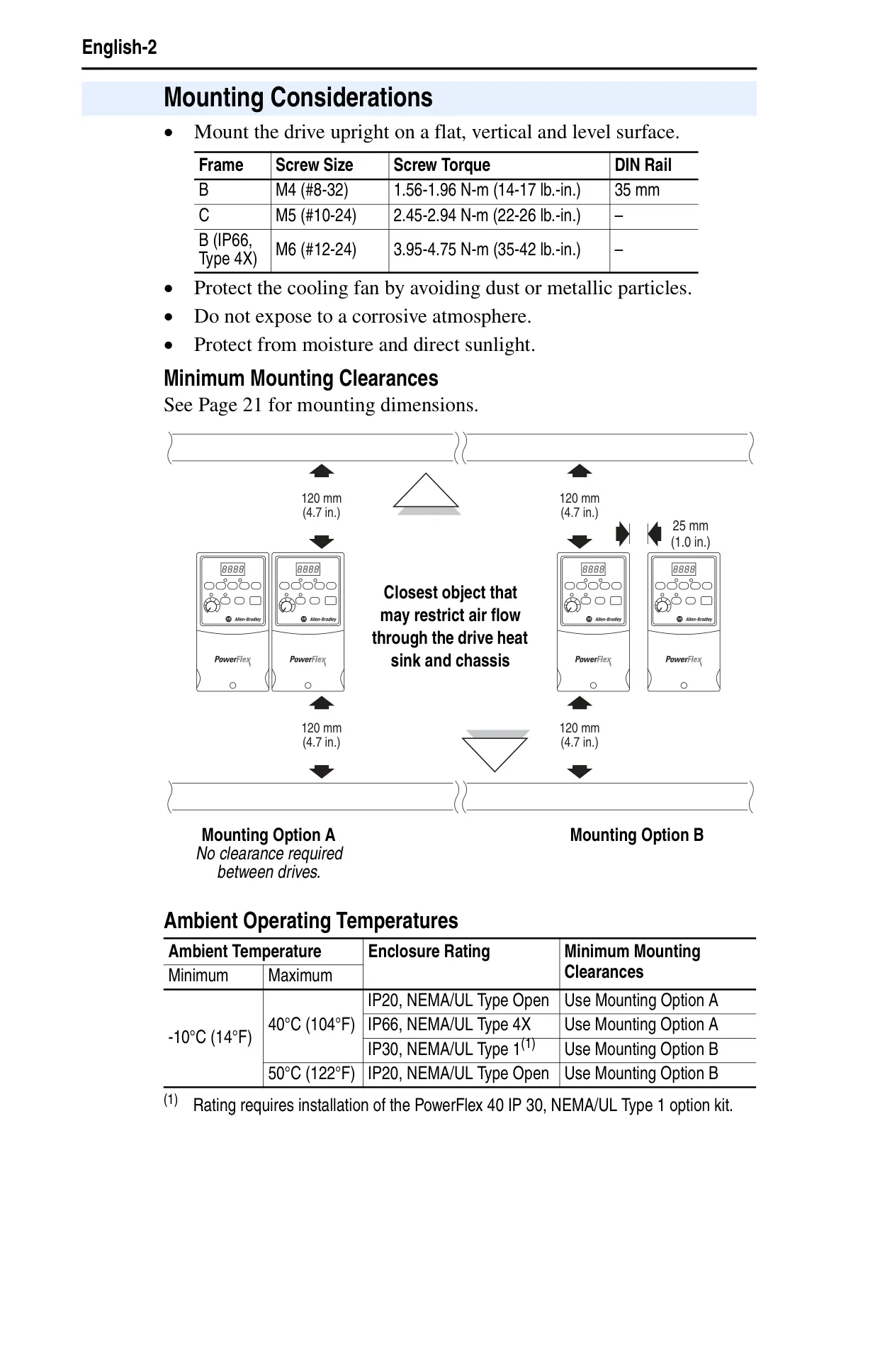
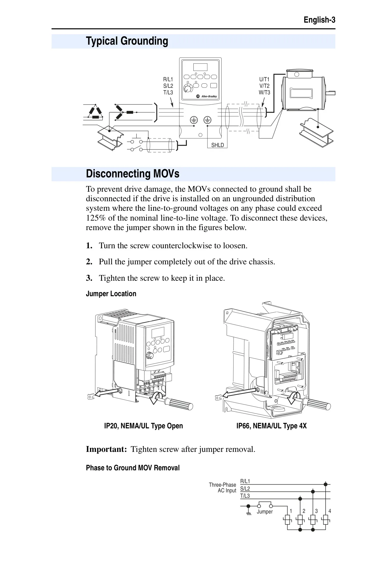
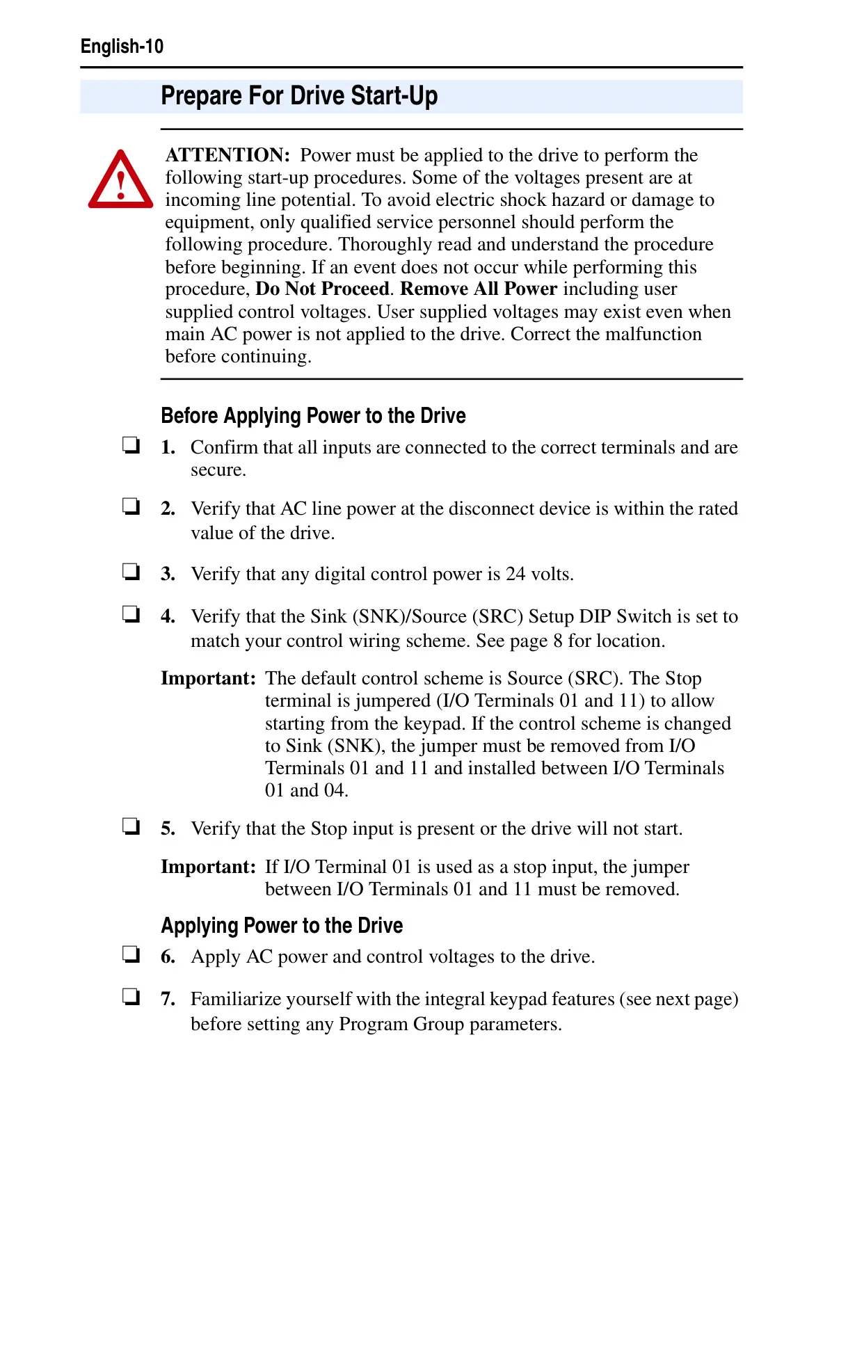
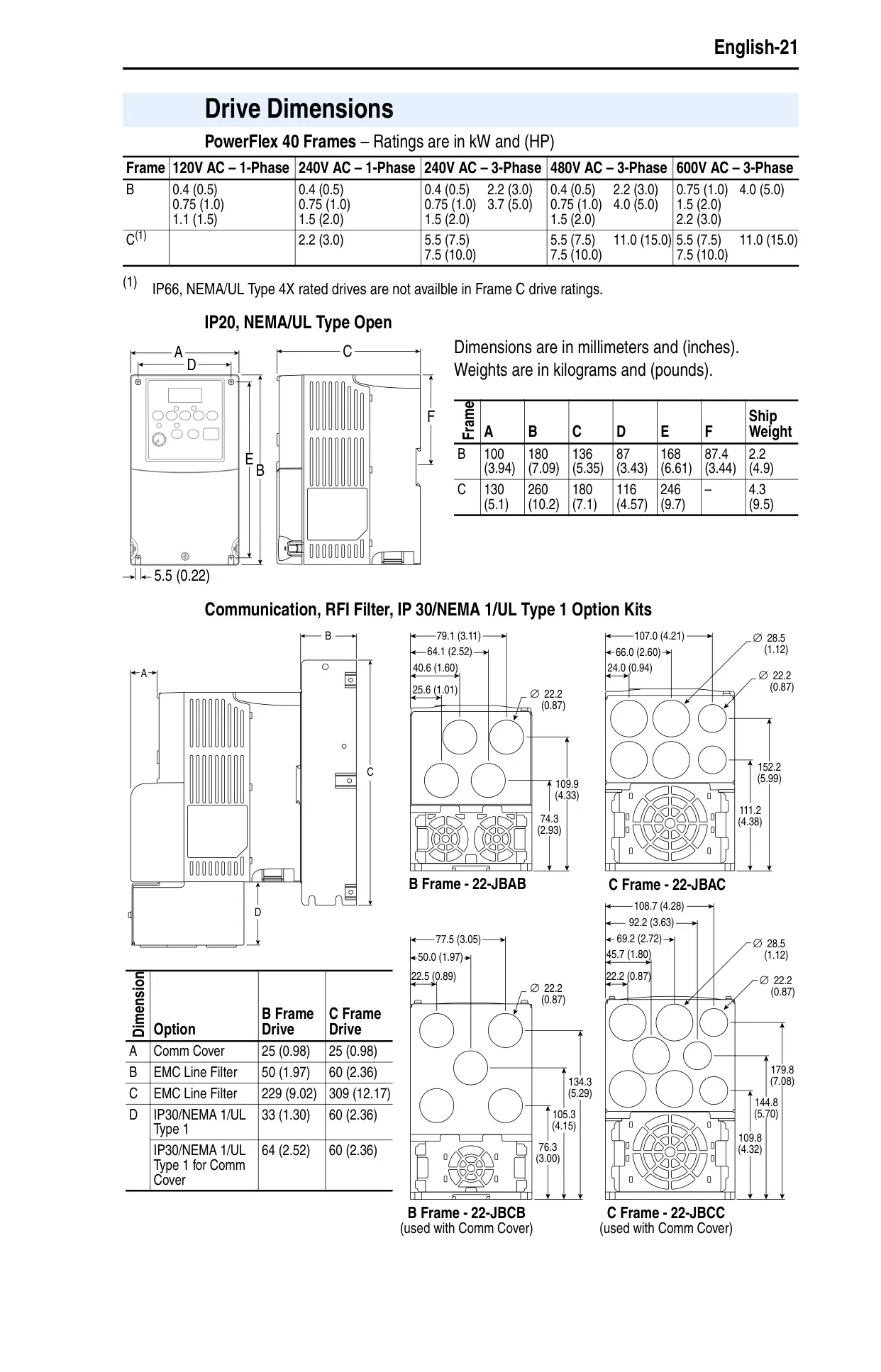
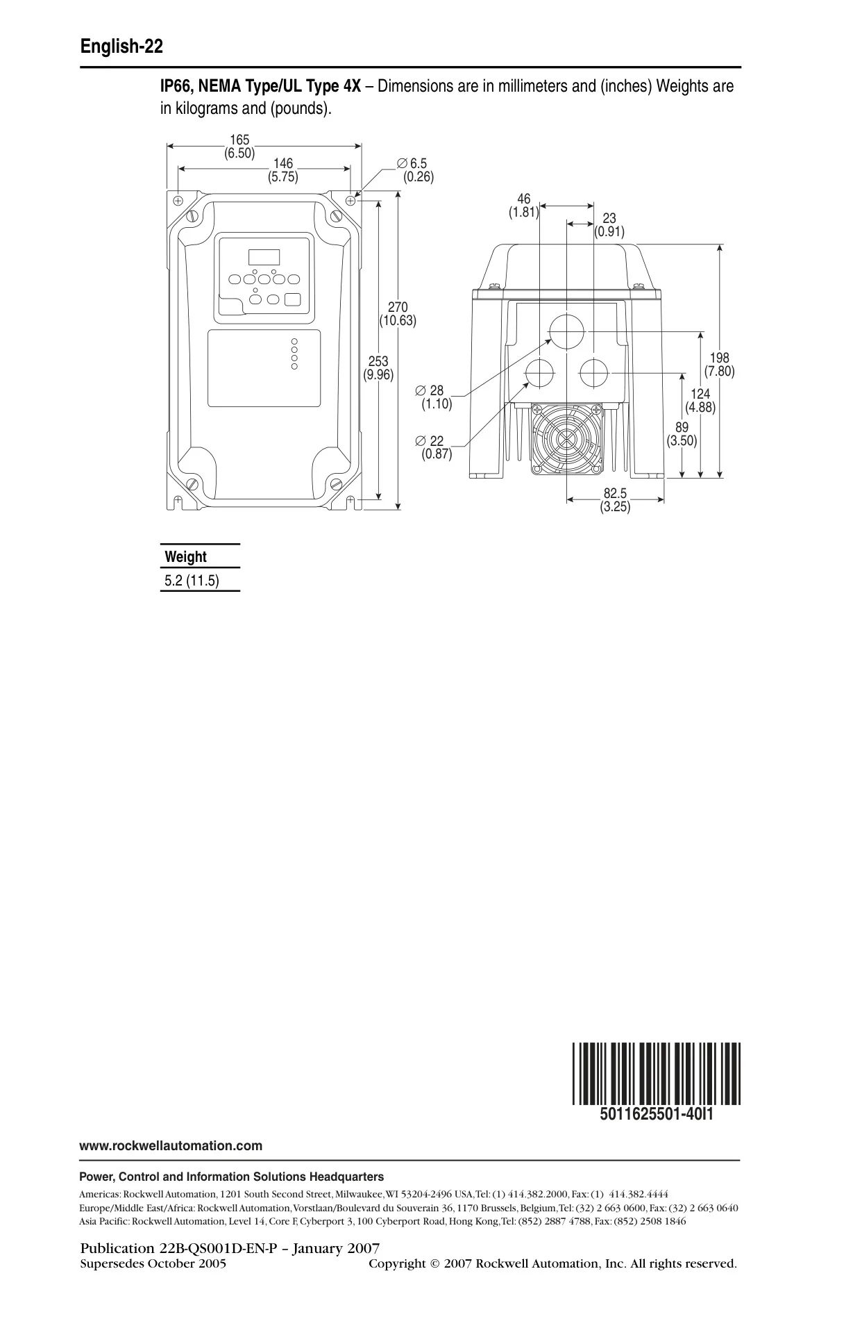
The Allen-Bradley PowerFlex 40 Adjustable Frequency AC Drive requires careful handling and installation. Users must be familiar with solid-state control characteristics, noting differences from electromechanical equipment. Critical safety guidelines emphasize waiting three minutes for capacitors to discharge after power removal to avoid electric shock. Installation should occur on a flat, vertical surface, protected from dust, corrosion, moisture, and direct sunlight, adhering to minimum mounting clearances. Proper grounding practices are paramount for safe and reliable operation.
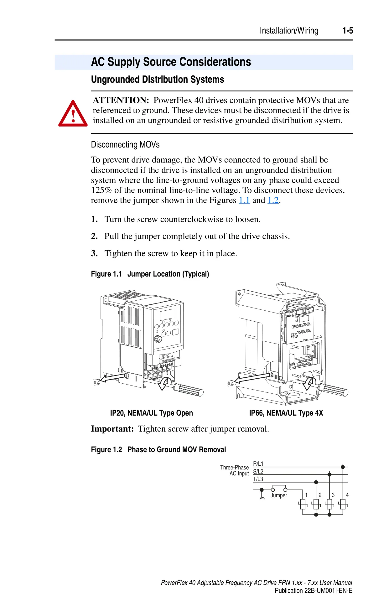
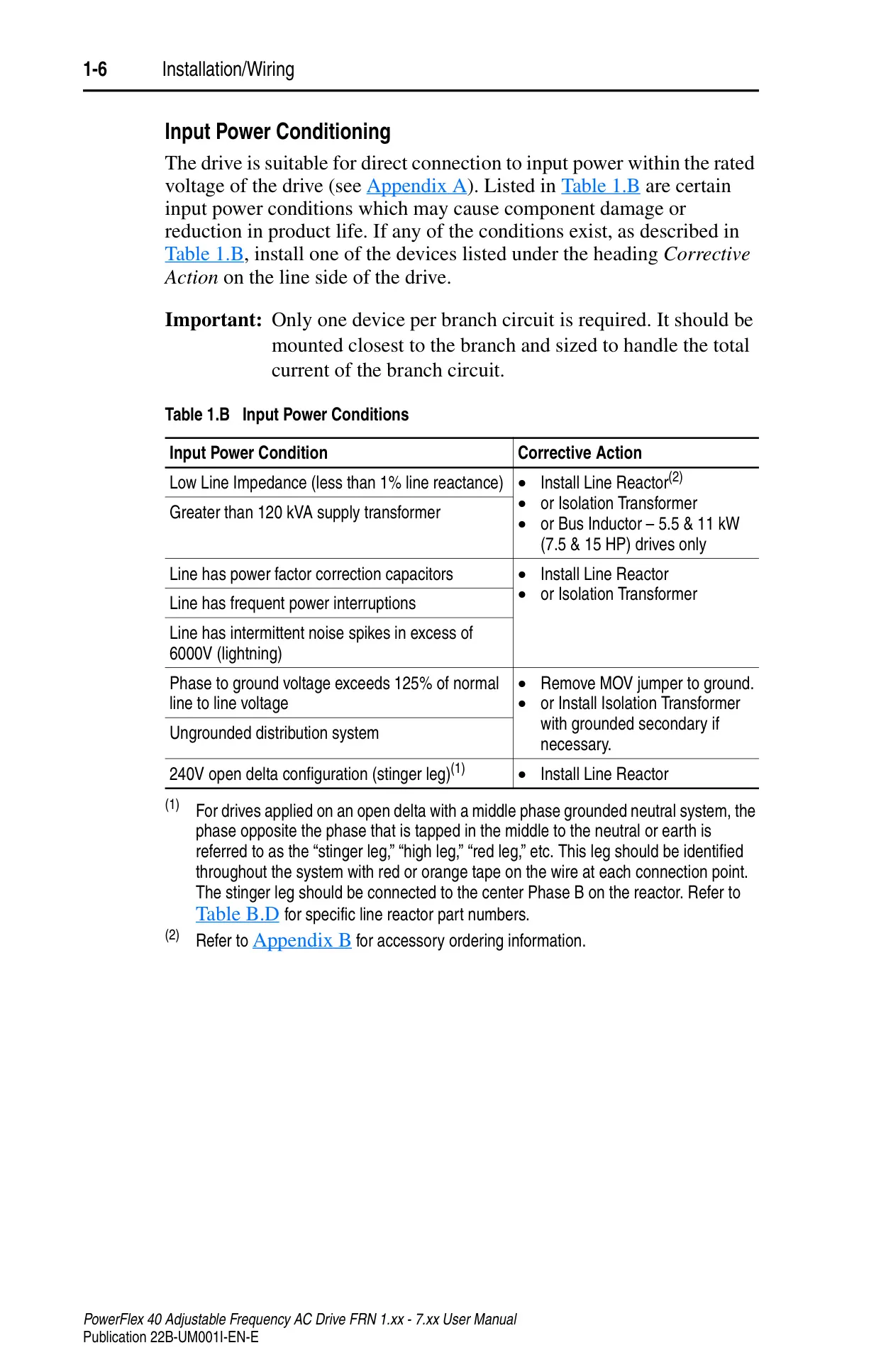
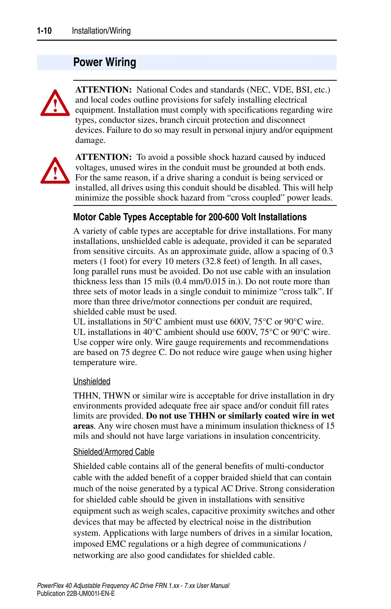
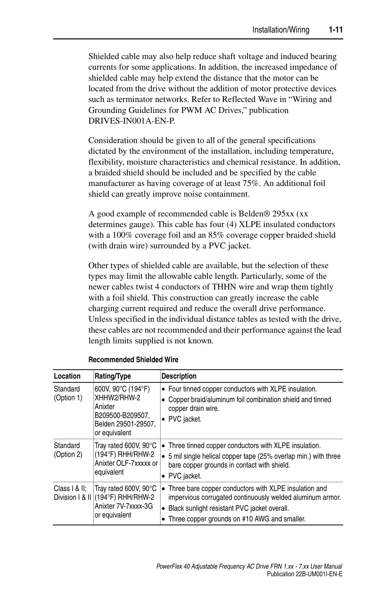
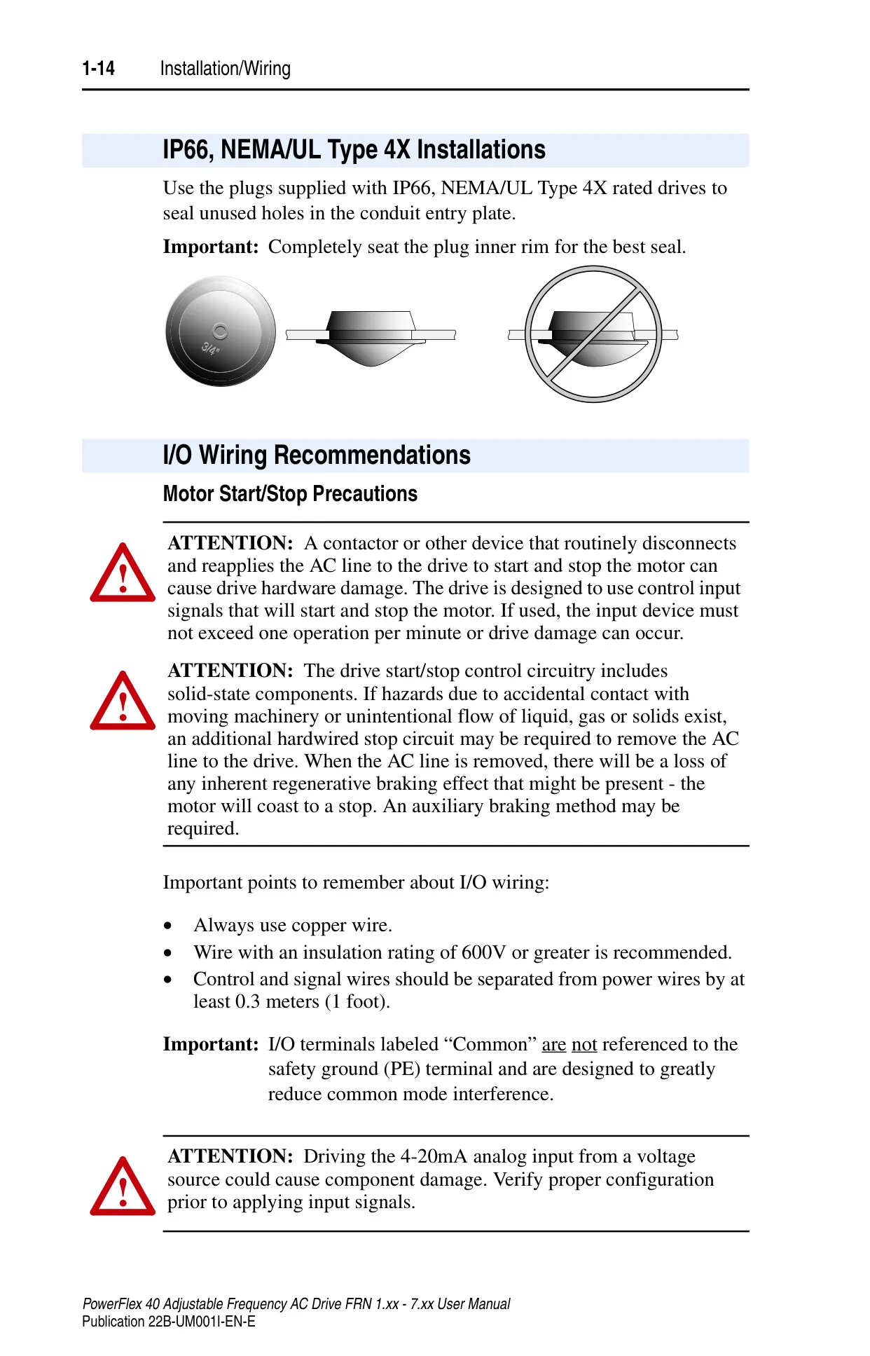
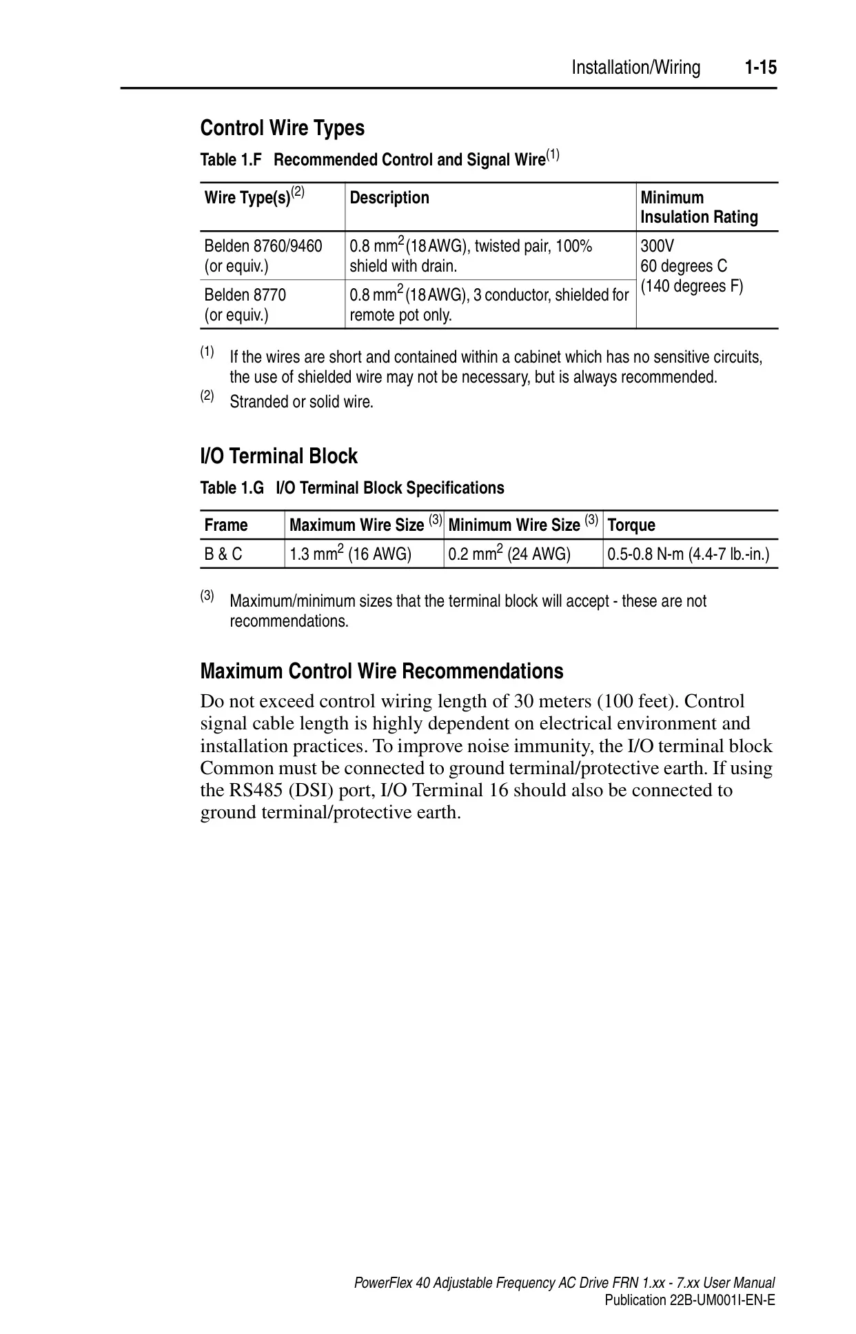
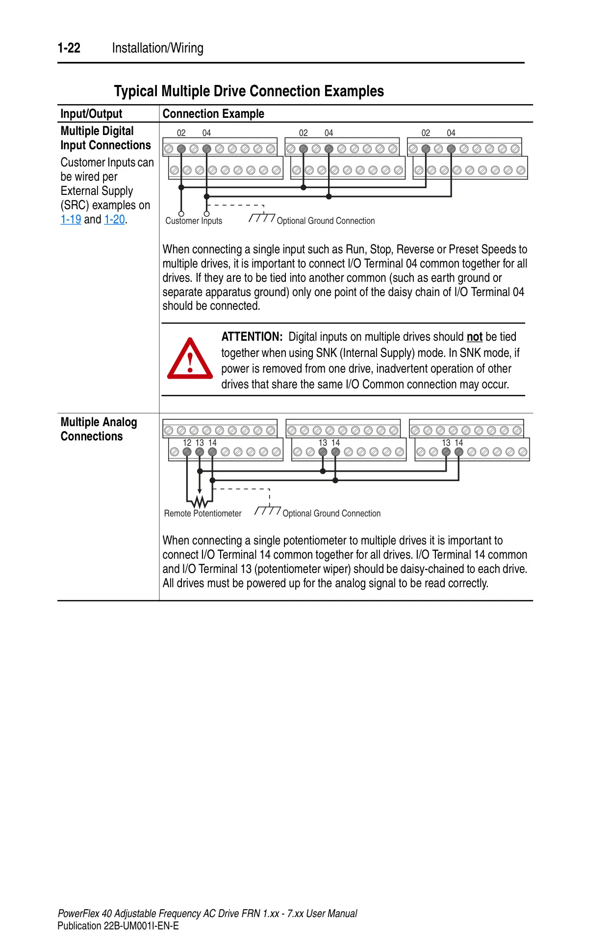
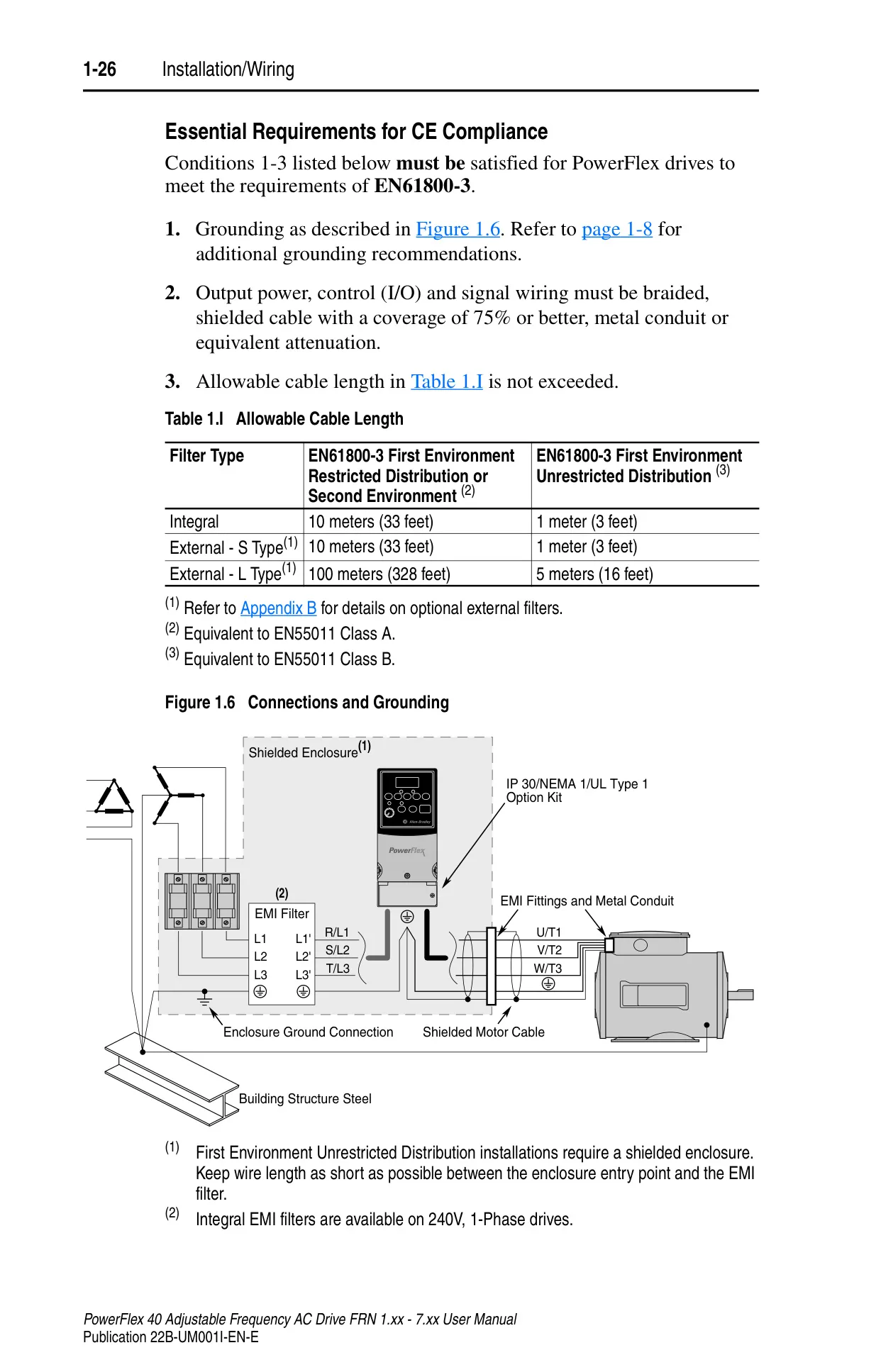
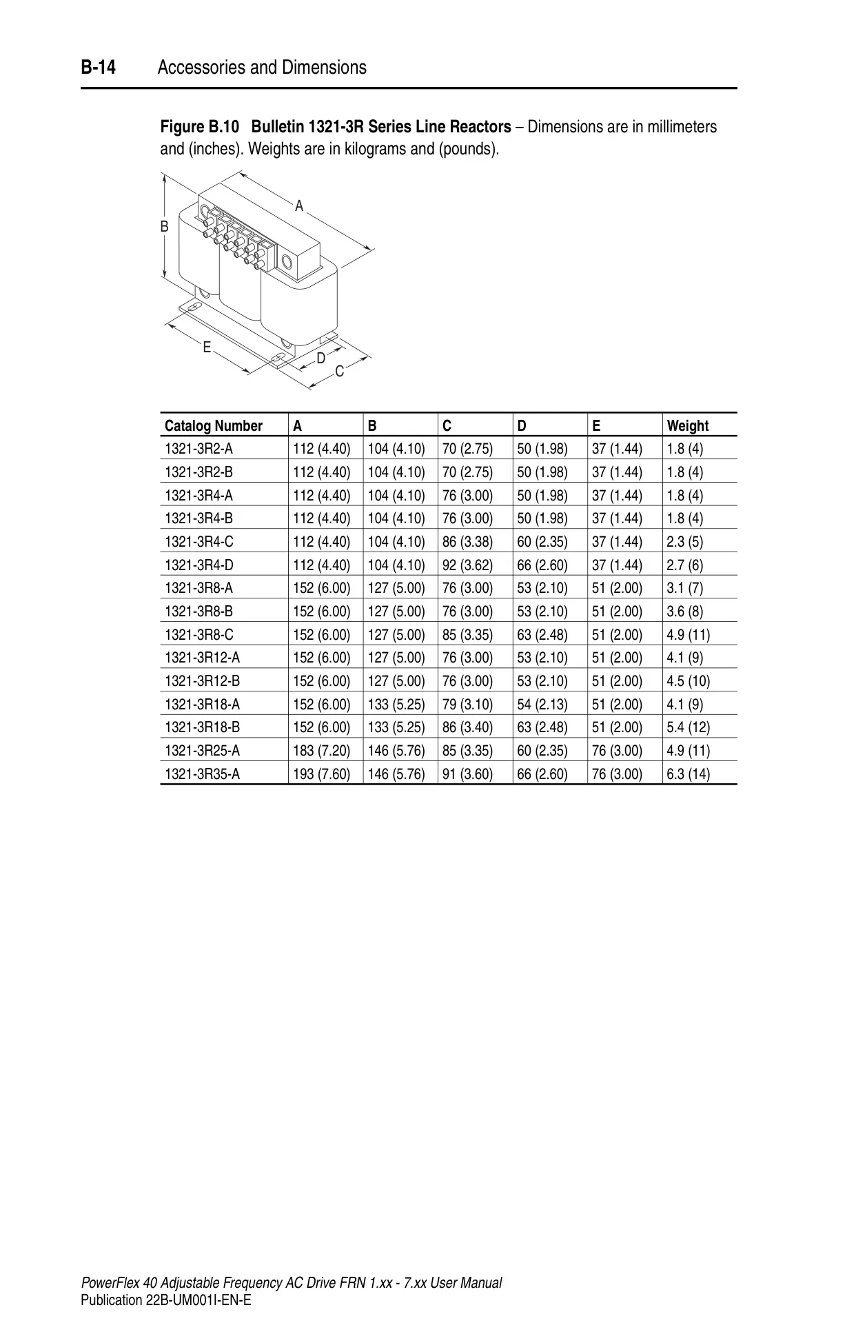
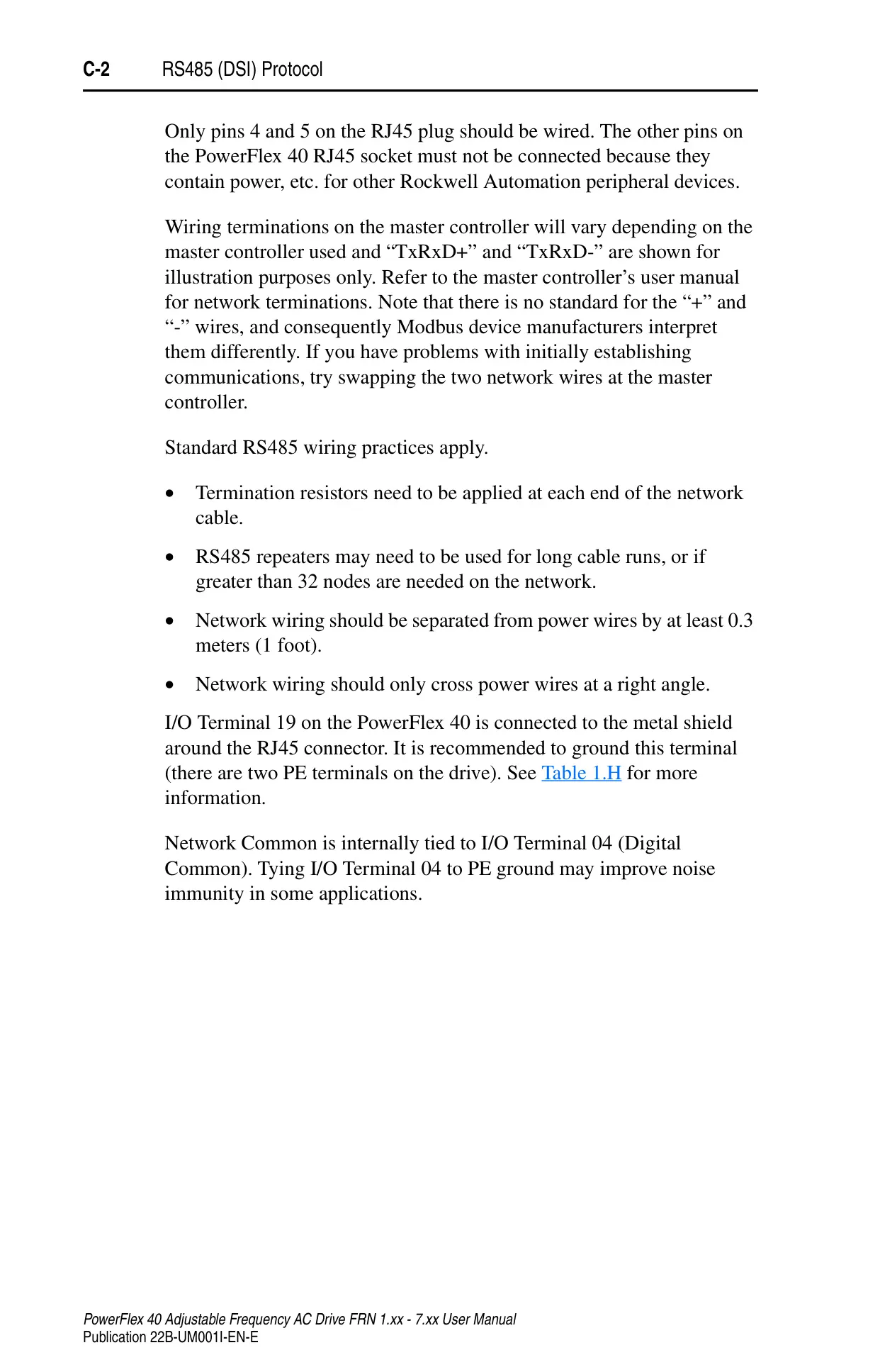
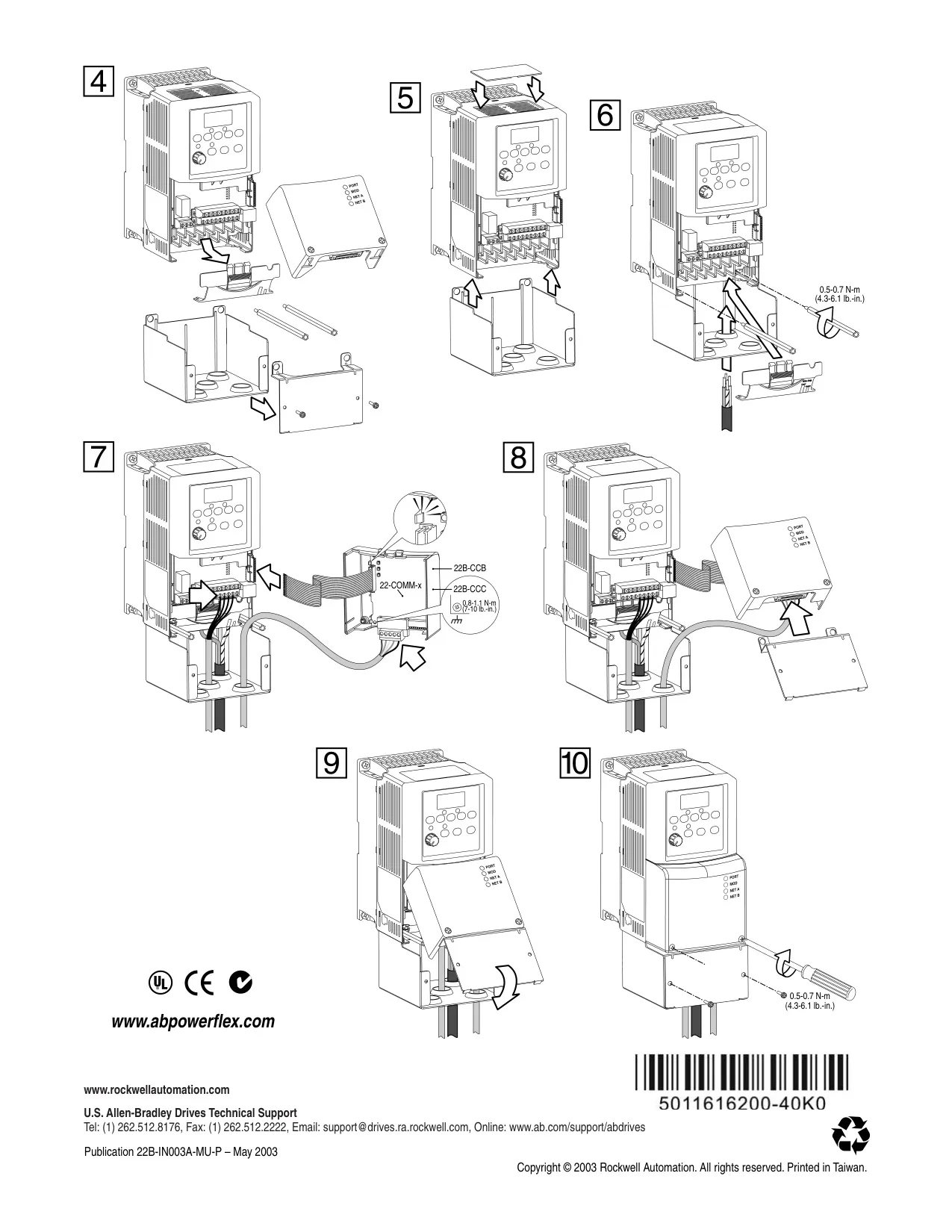
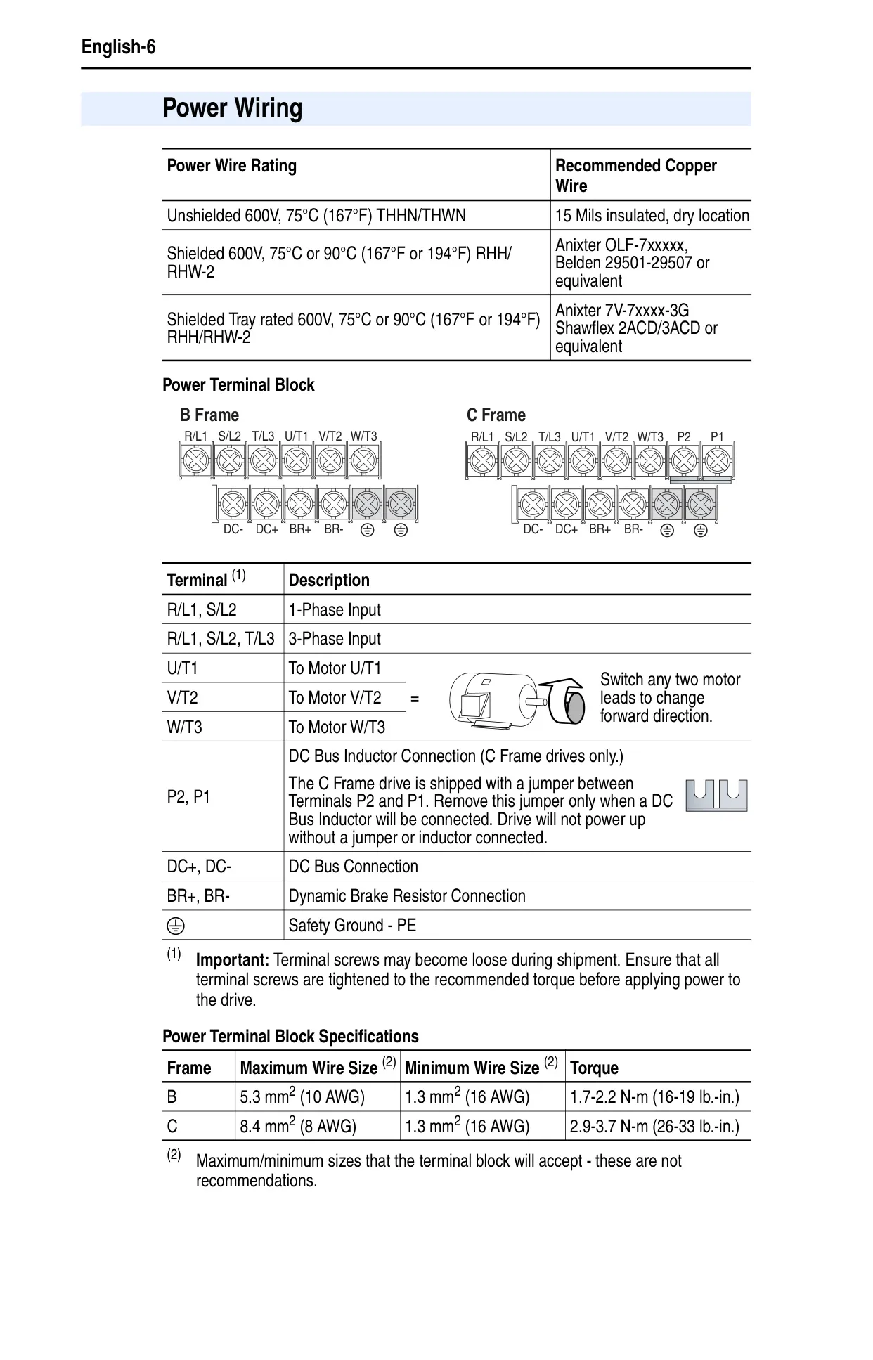
Wiring is crucial for optimal drive performance. The manual stresses the use of copper wire with 600V insulation, advising separation from power wires by at least 0.3 meters. Both unshielded and shielded/armored cables are discussed, with recommendations for reducing electrical noise, especially in installations with sensitive equipment or long cable runs. The drive supports various input power conditions, often requiring line reactors or isolation transformers for protection, particularly with low line impedance or power factor correction capacitors.
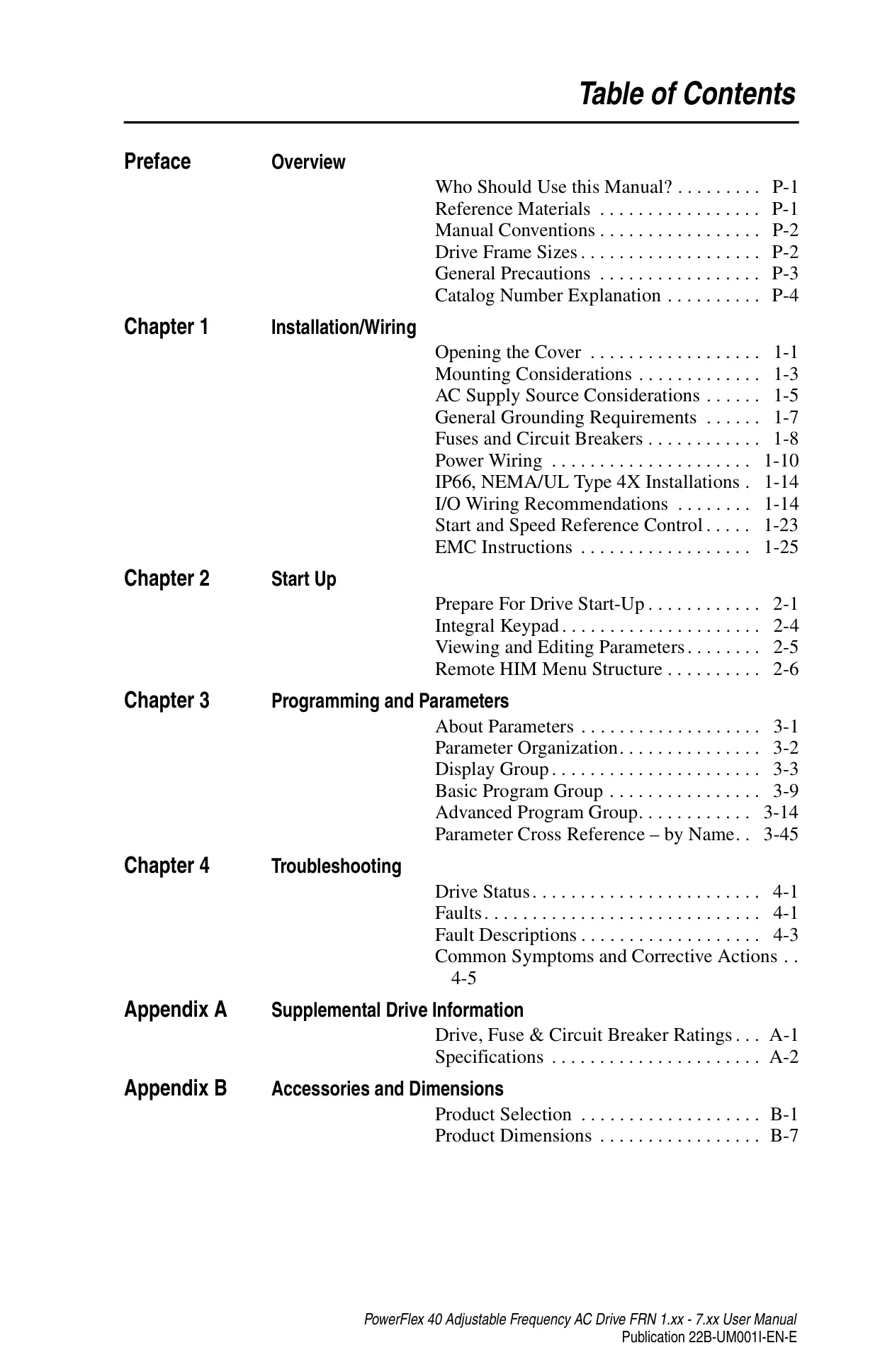
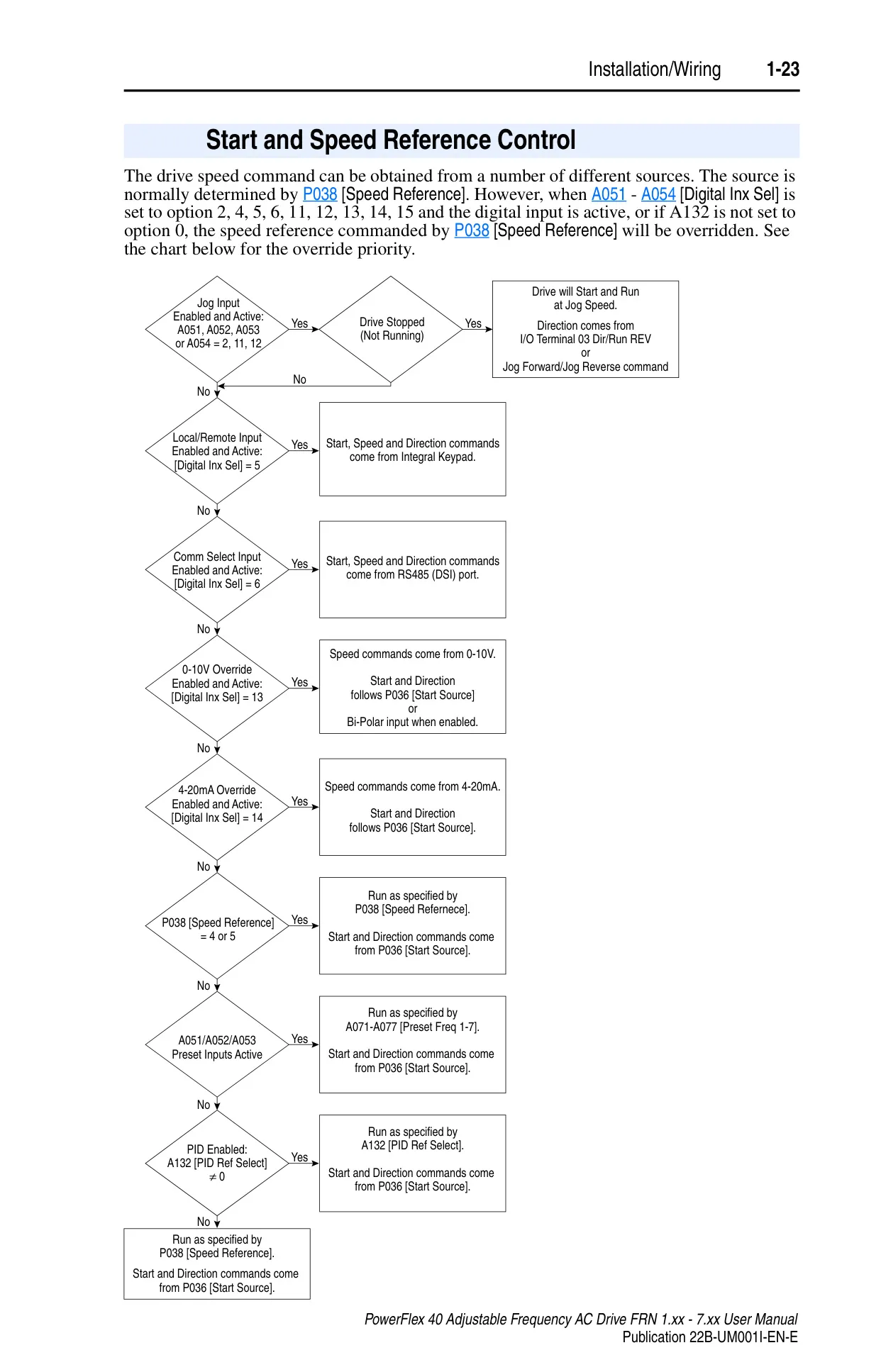
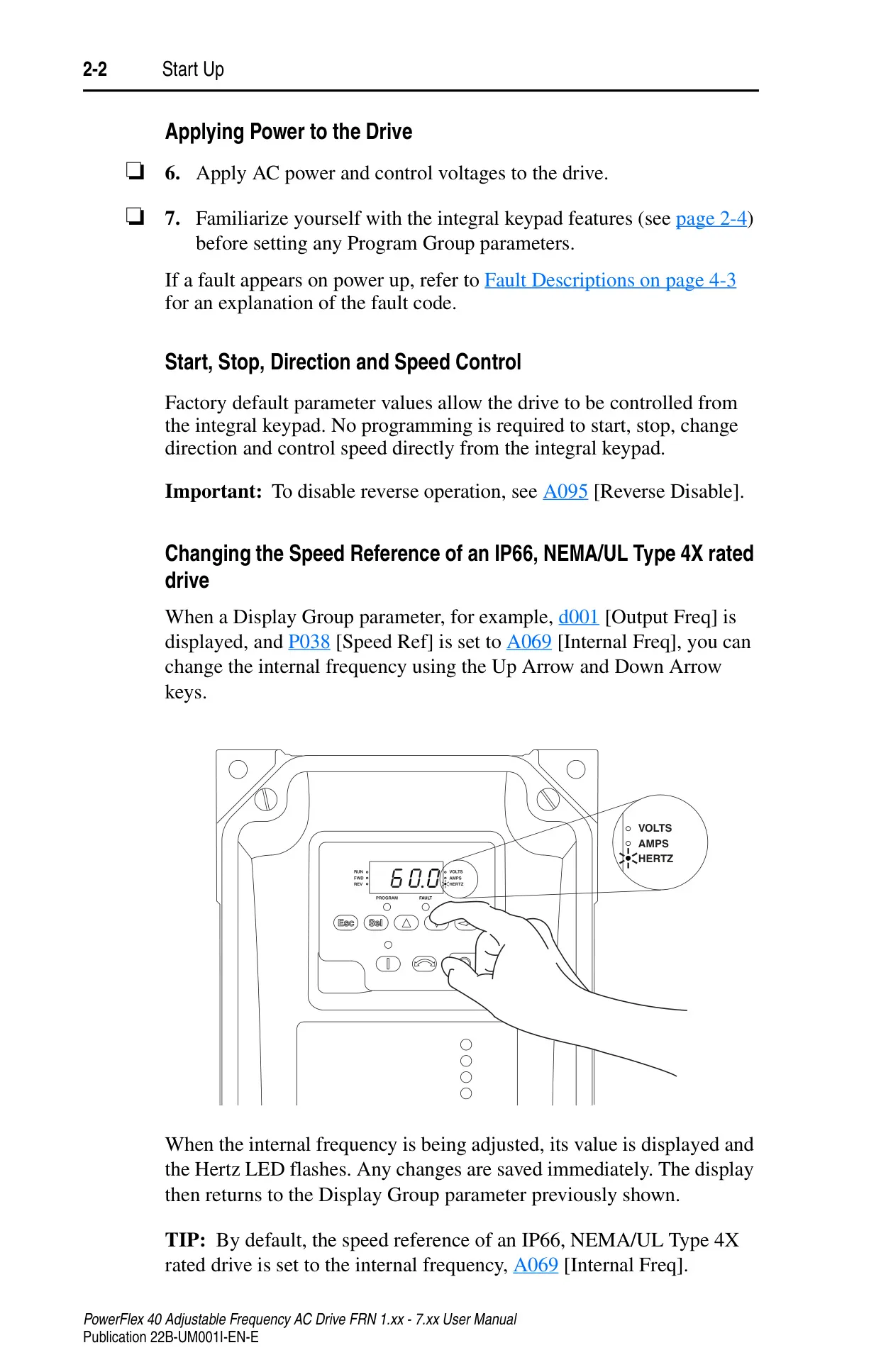
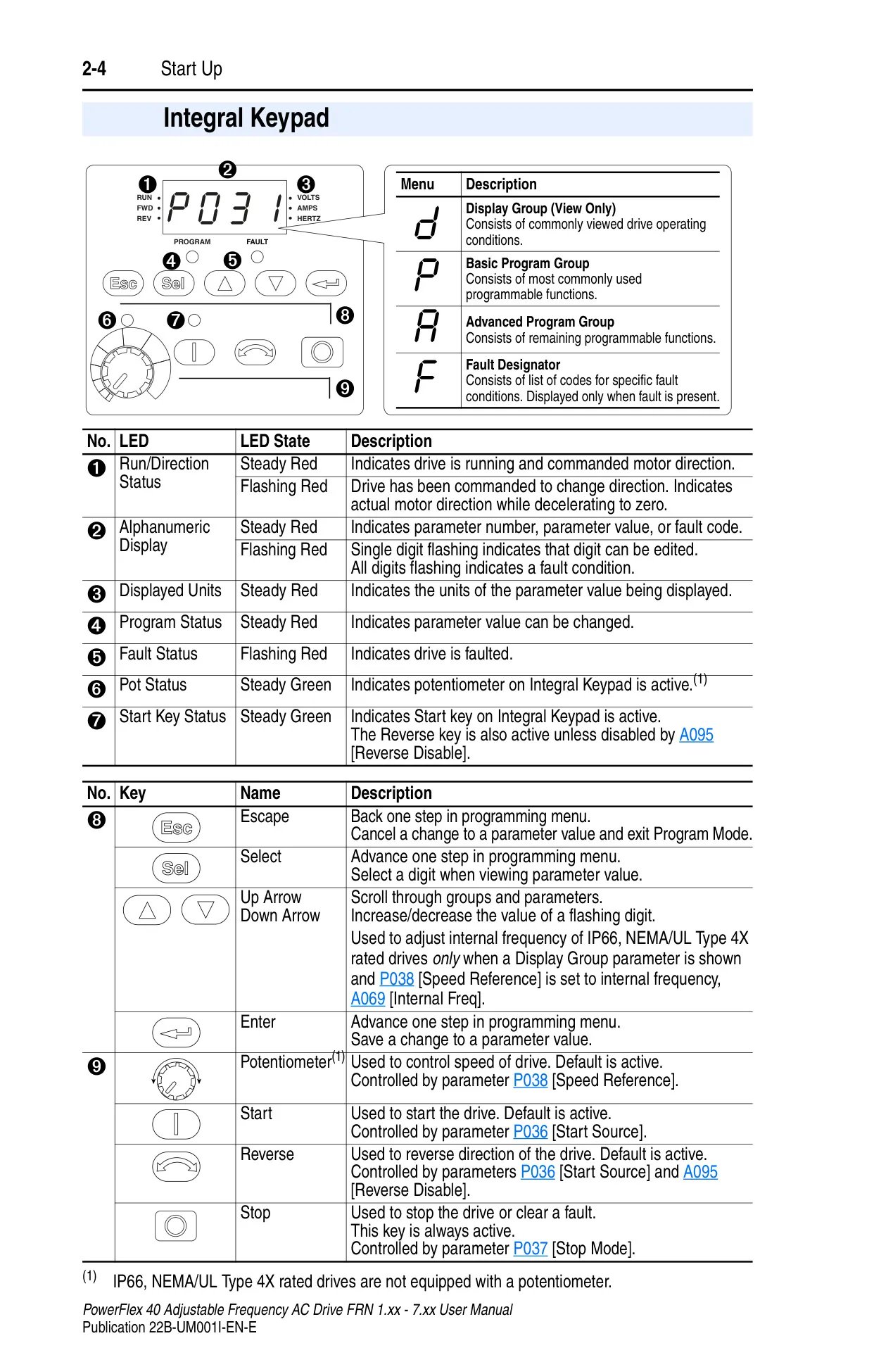
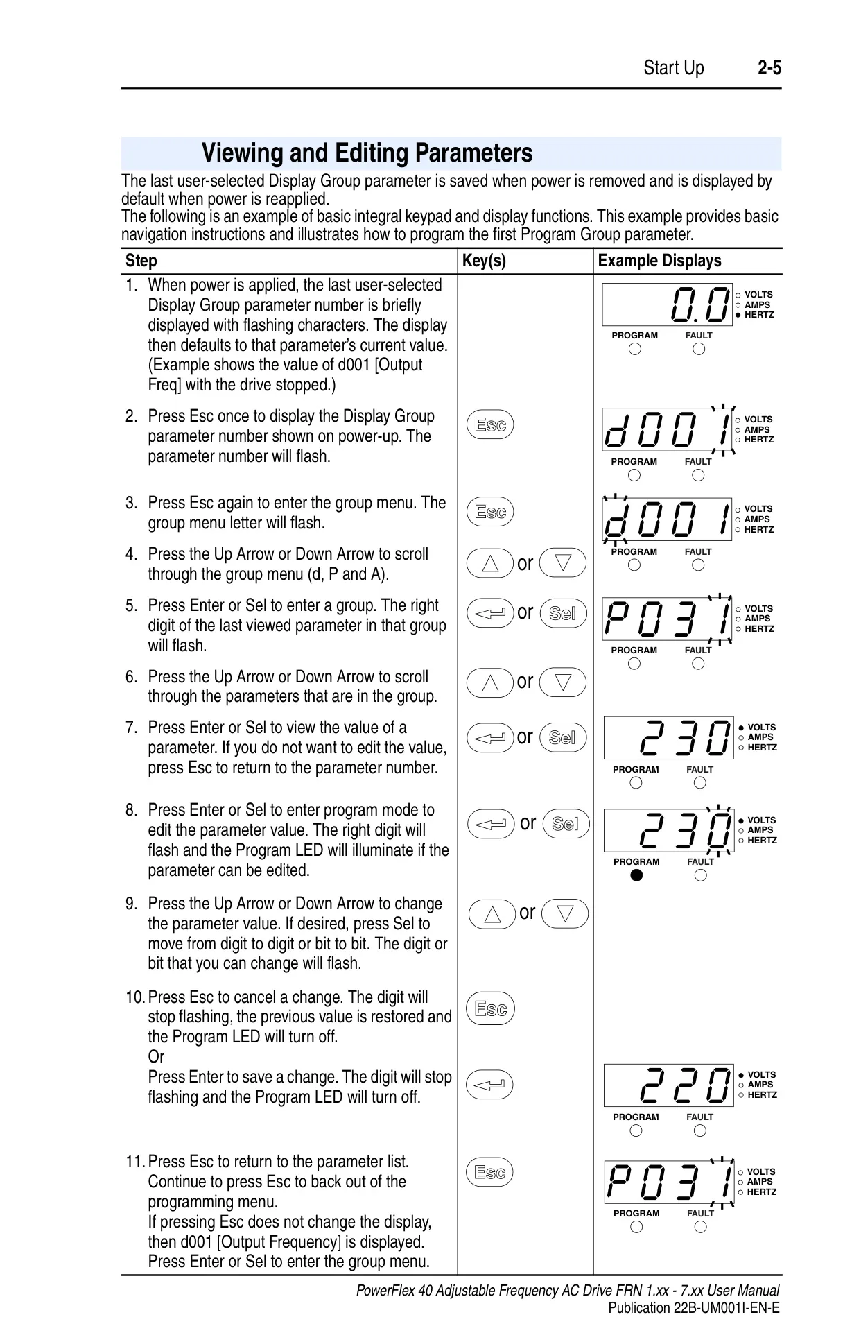
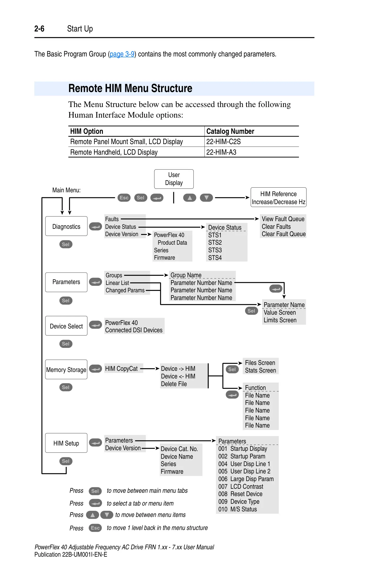
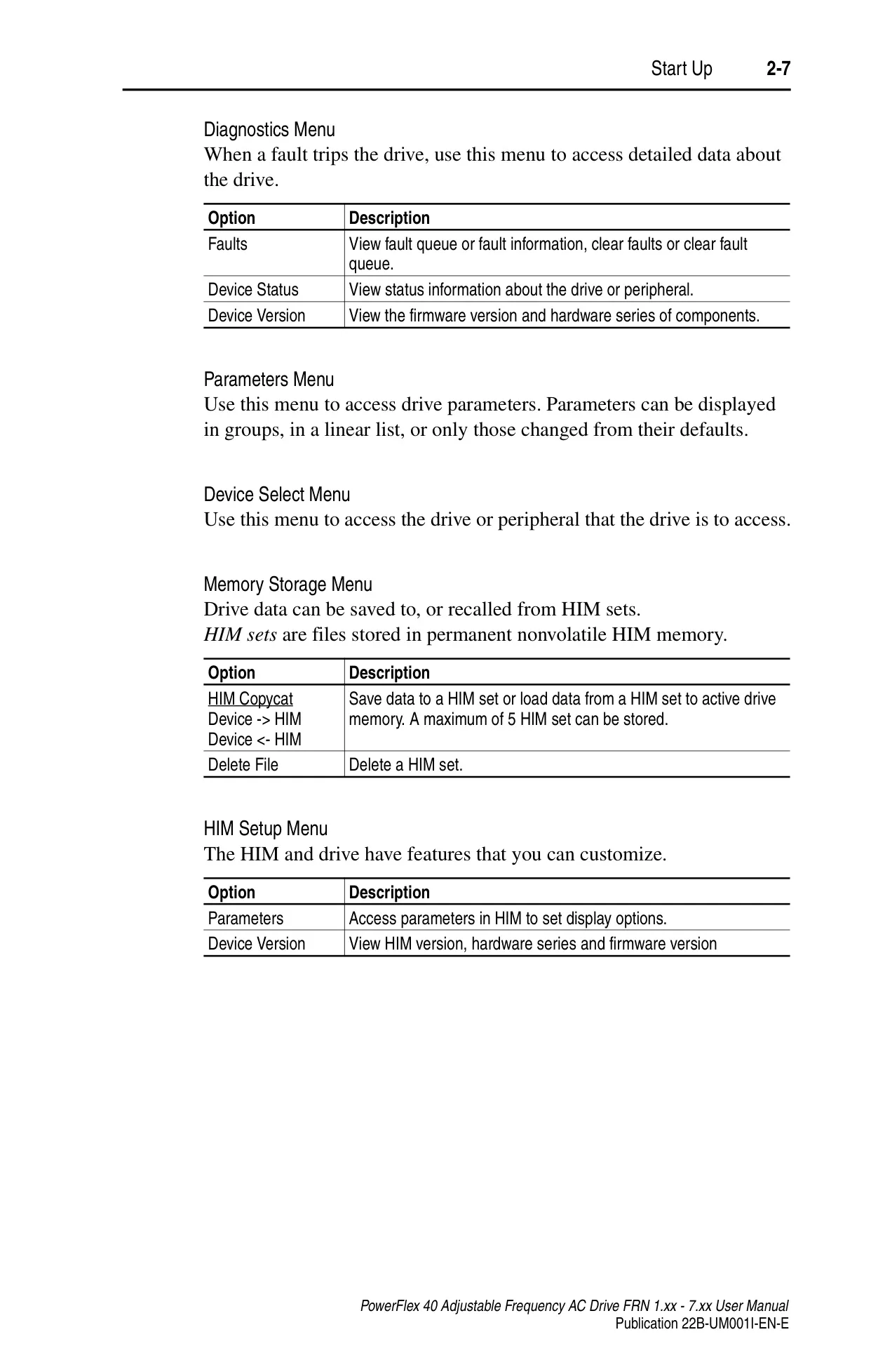
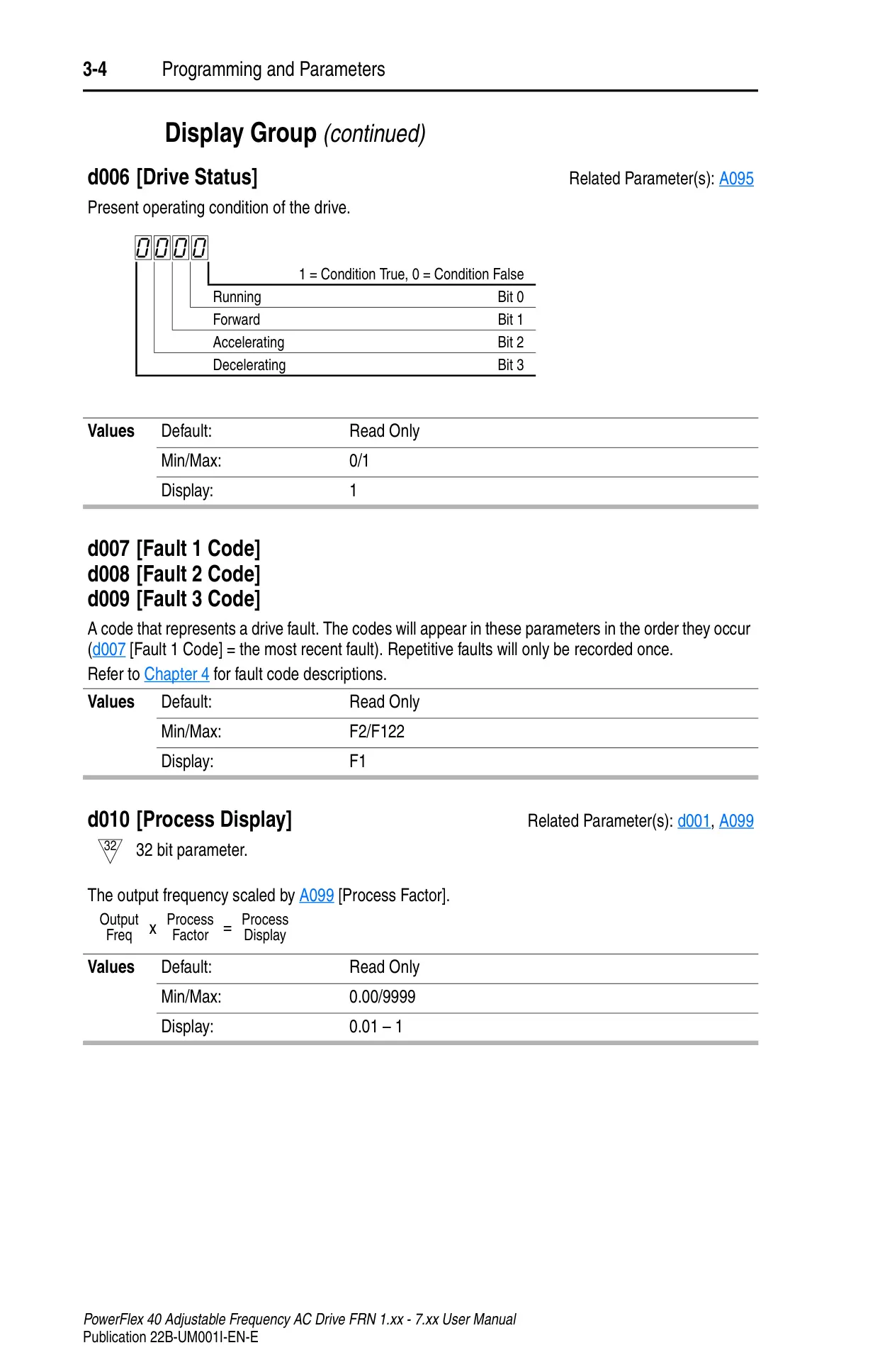
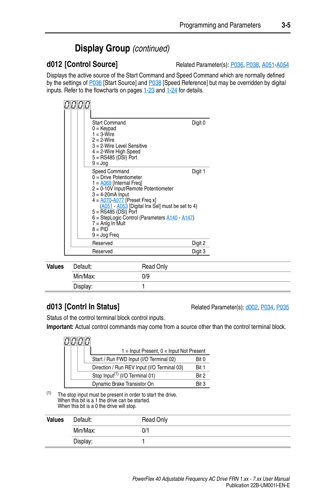
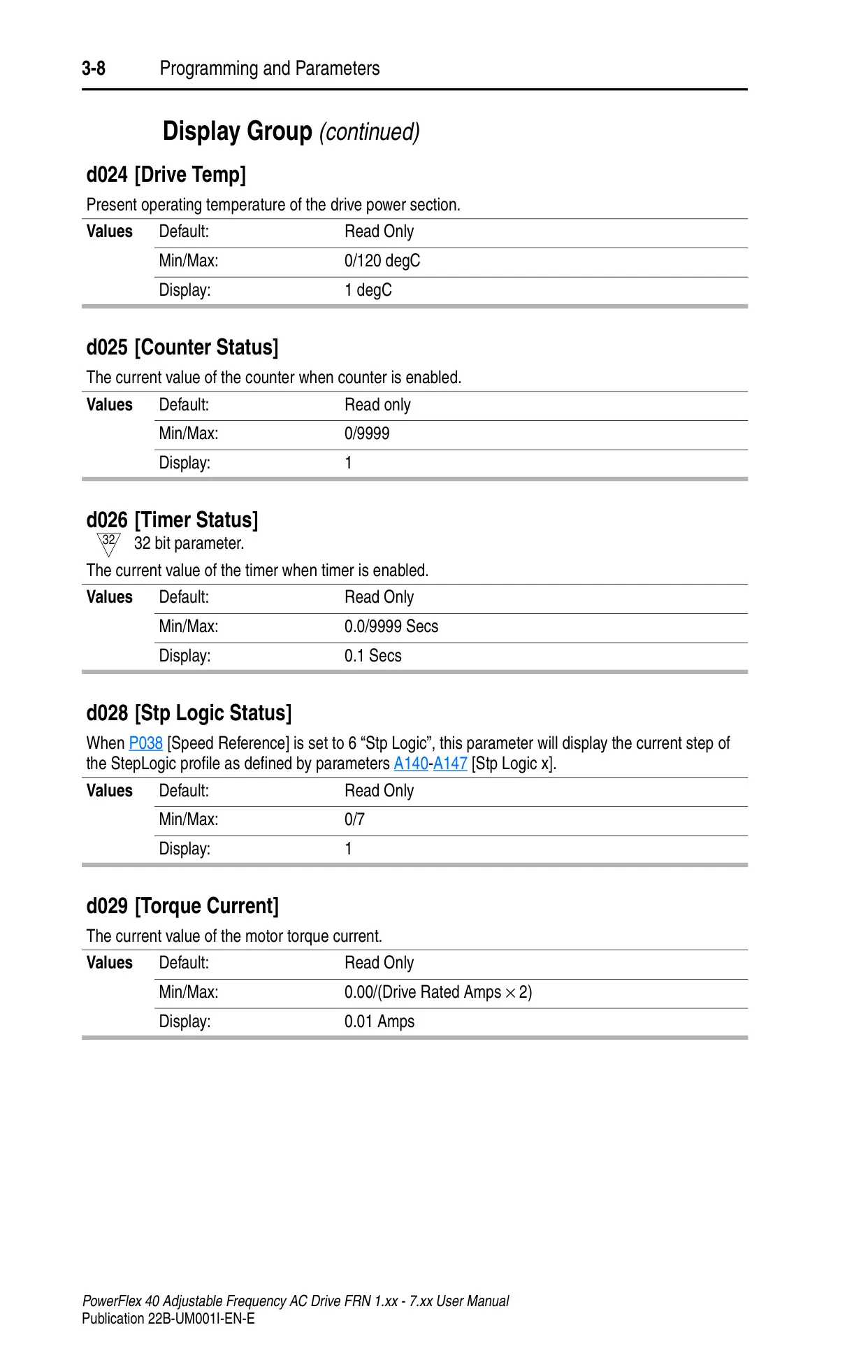
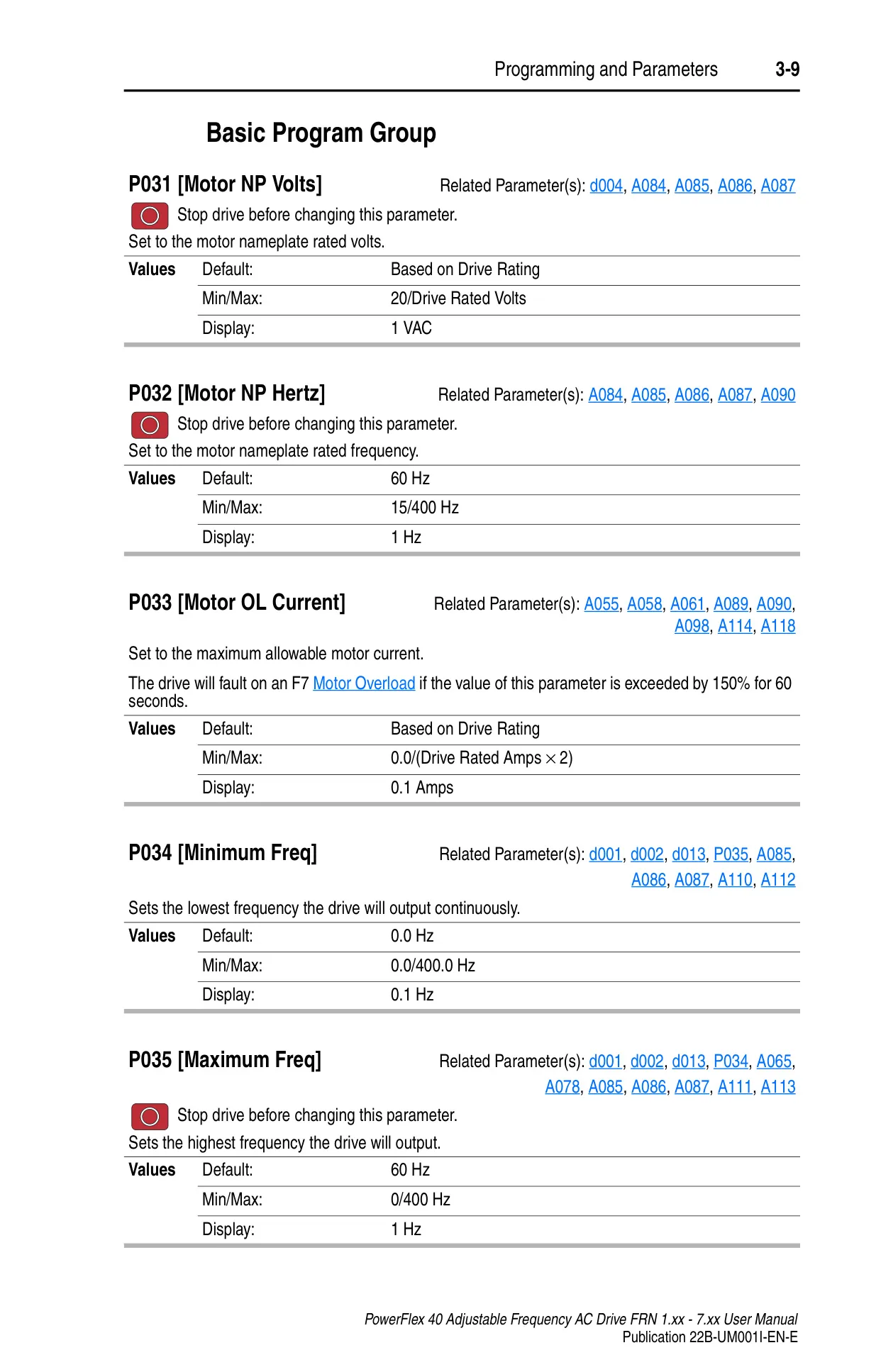
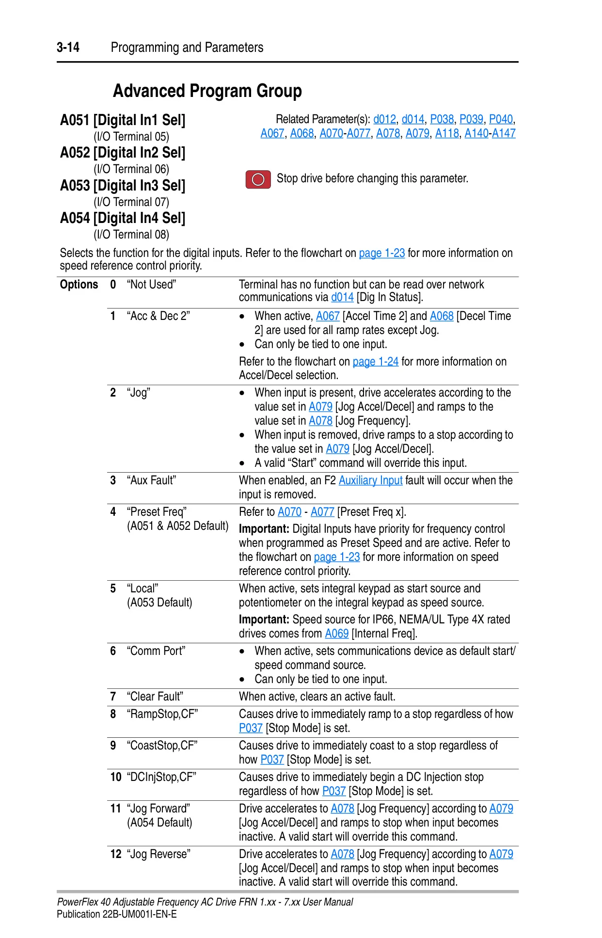
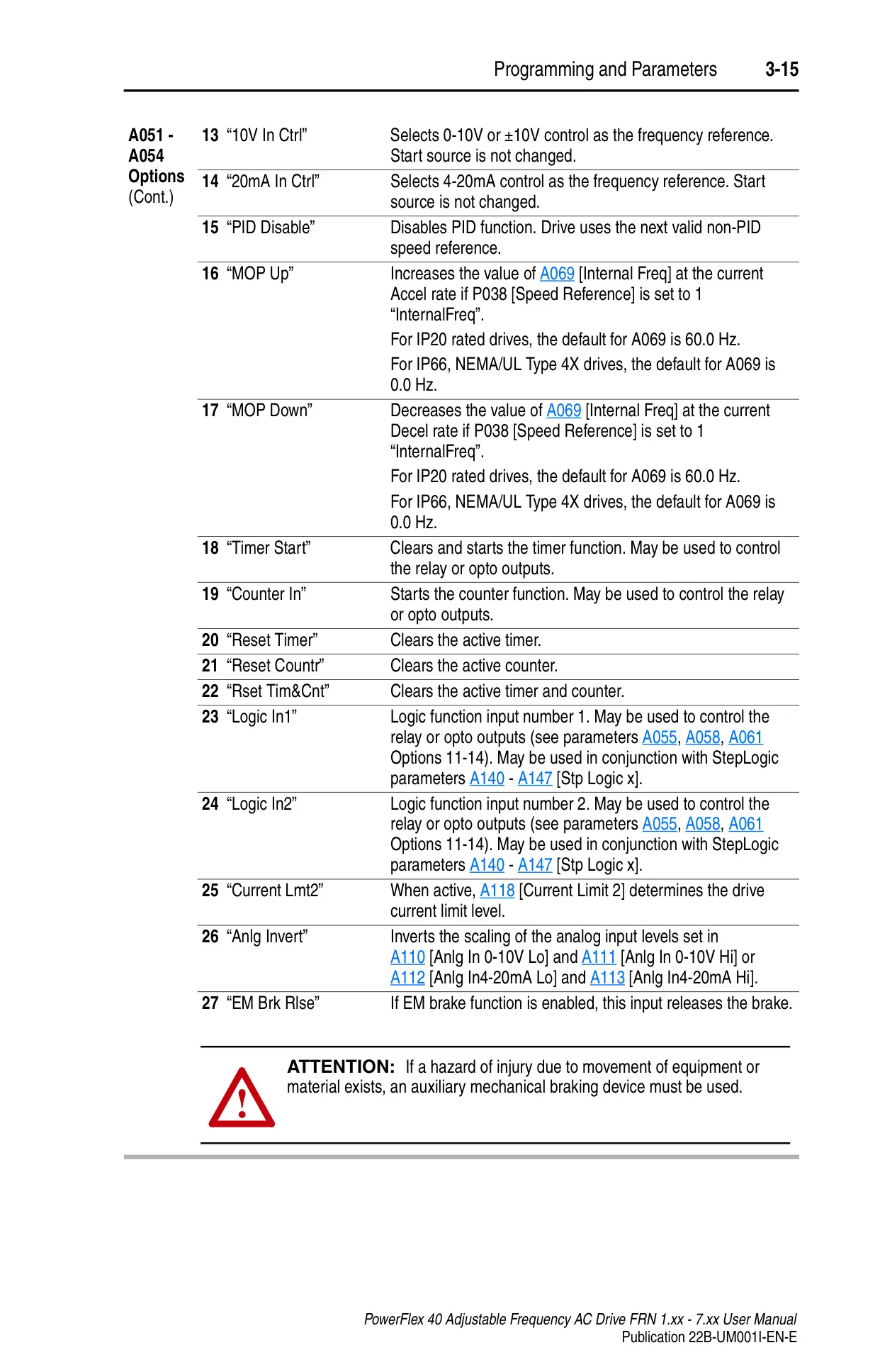
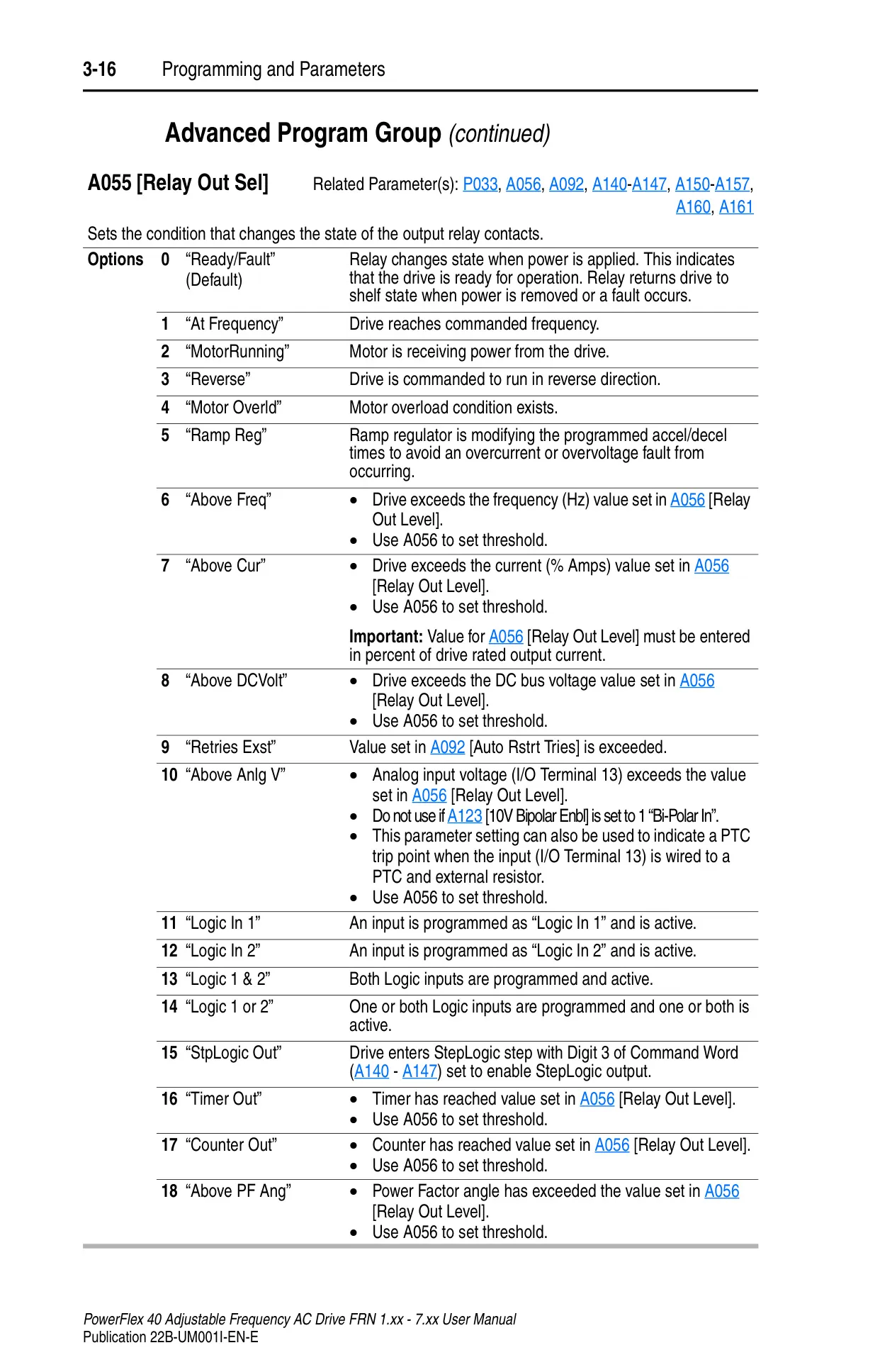
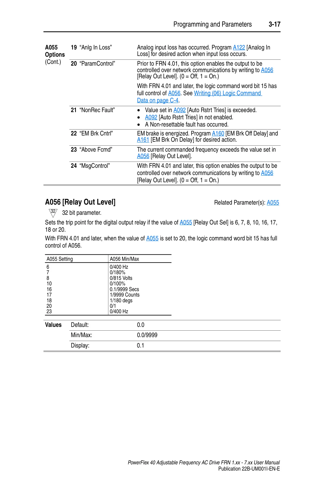
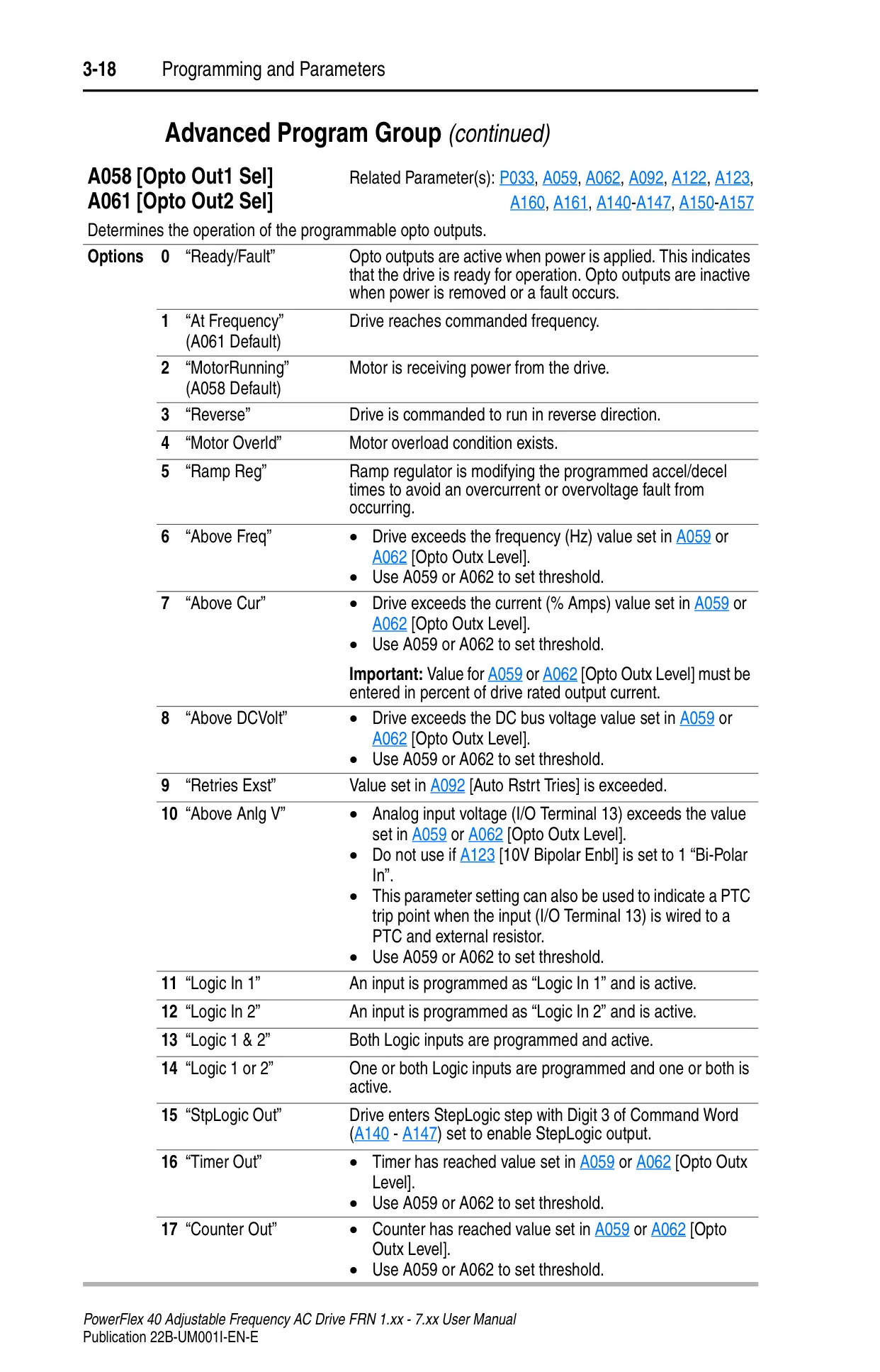
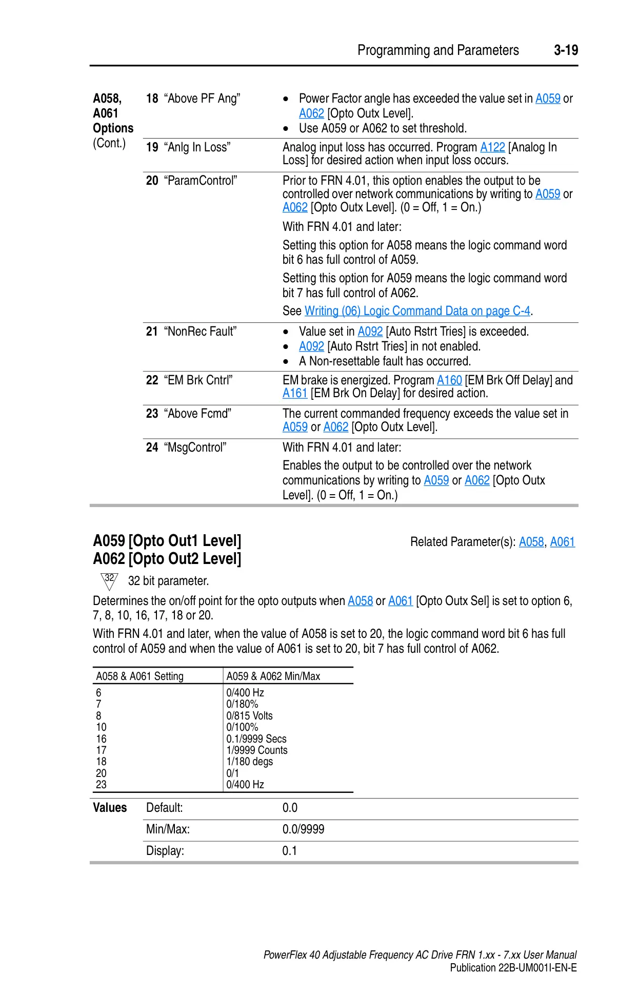
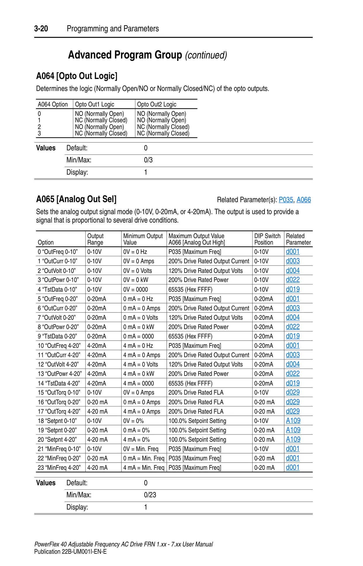
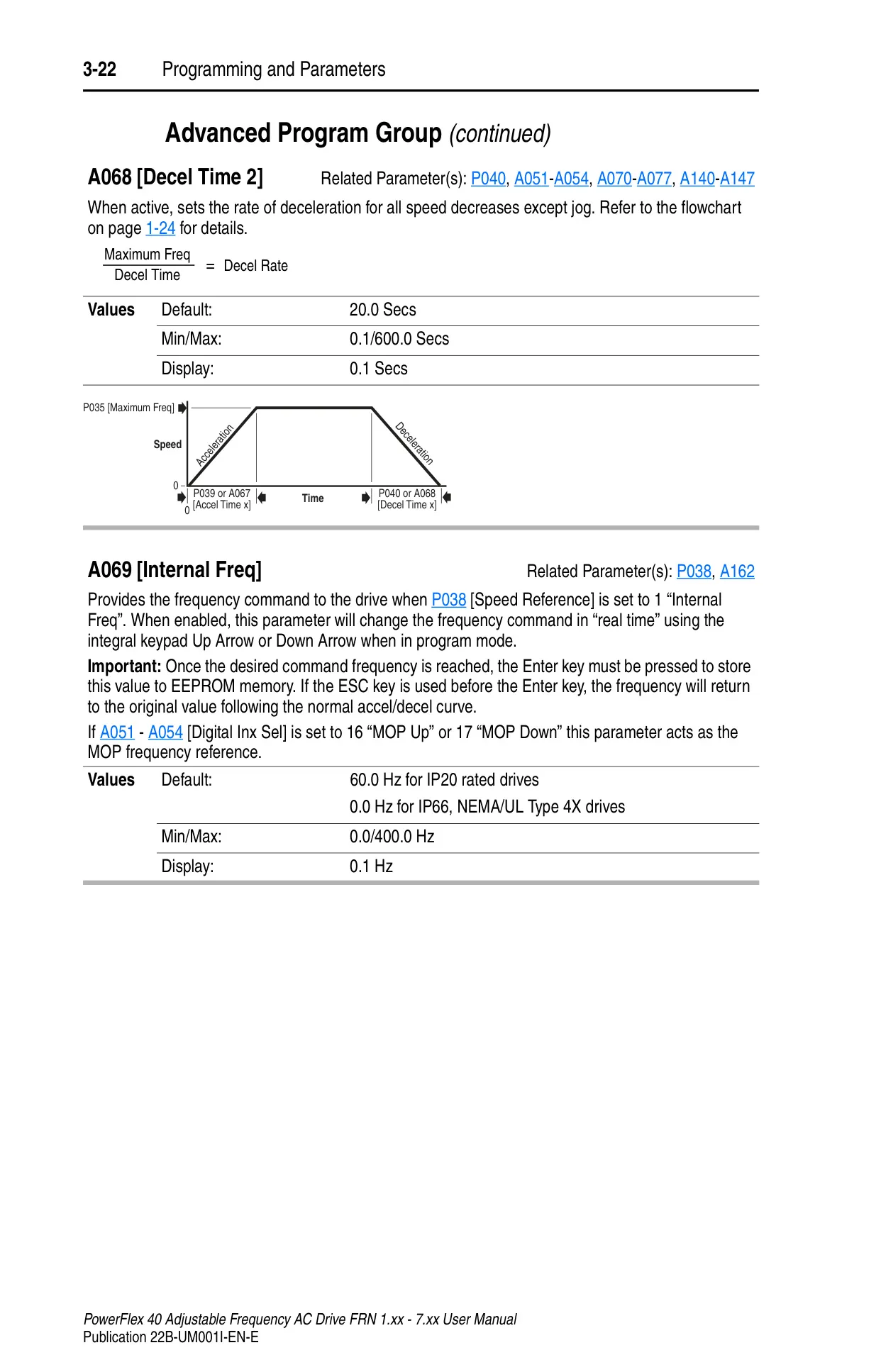
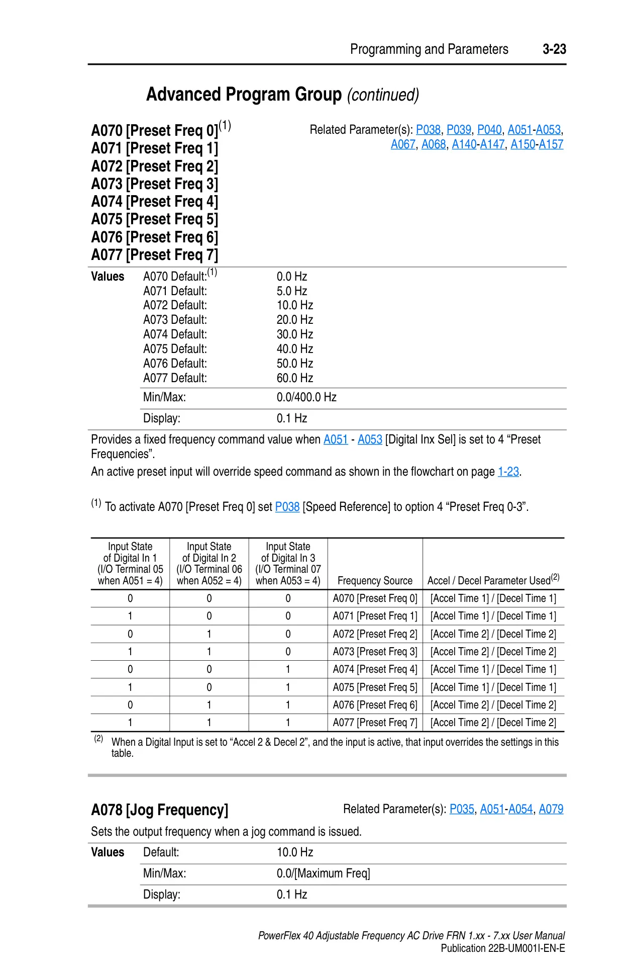
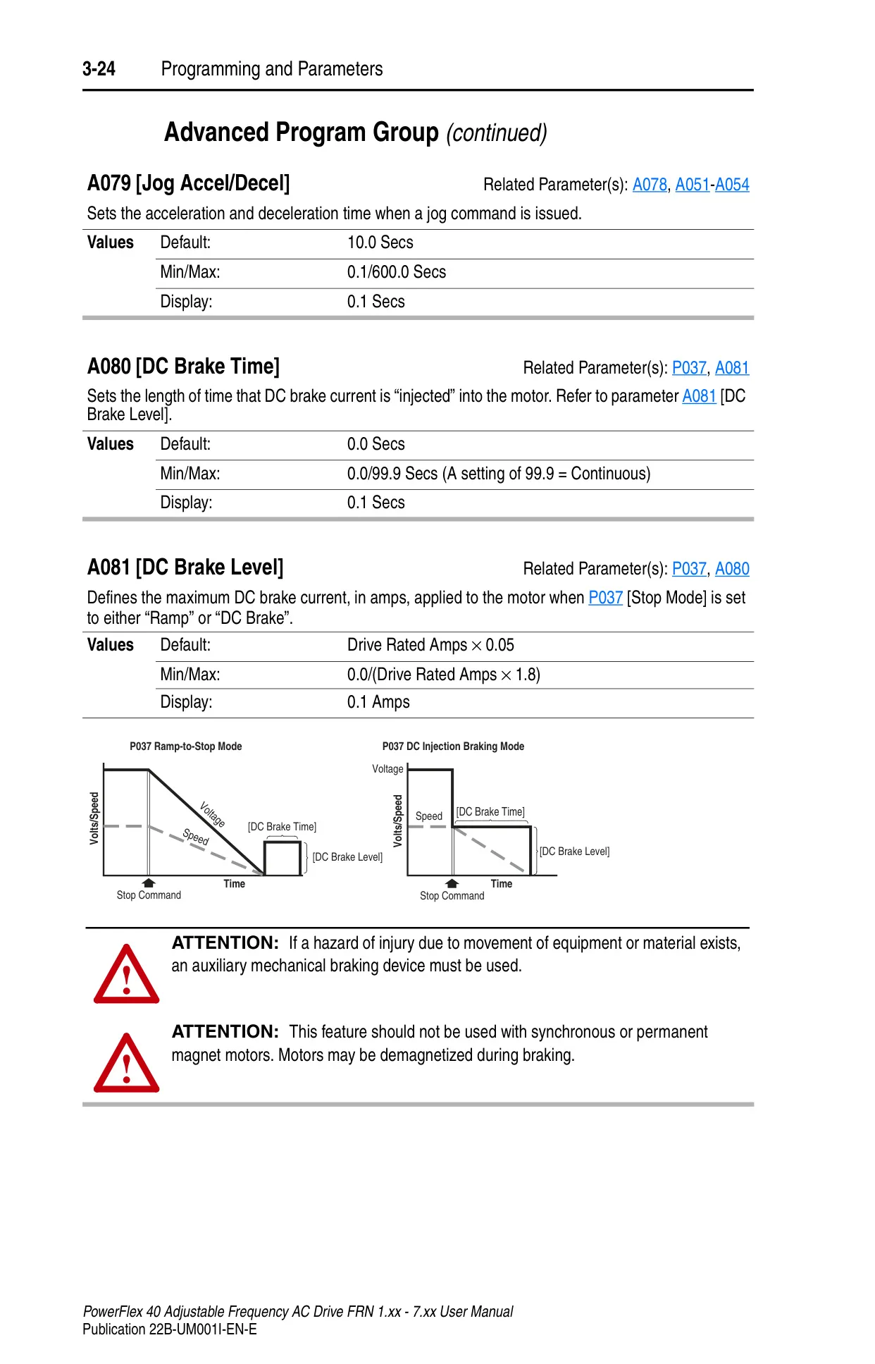
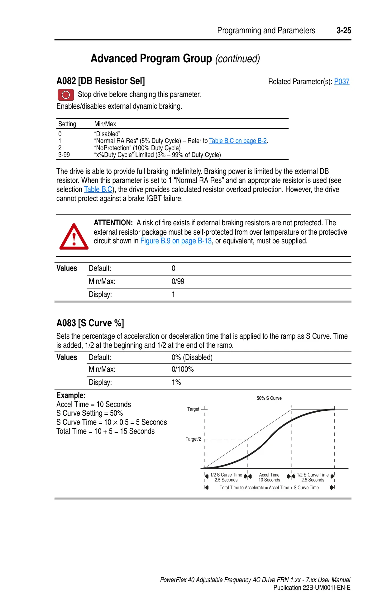
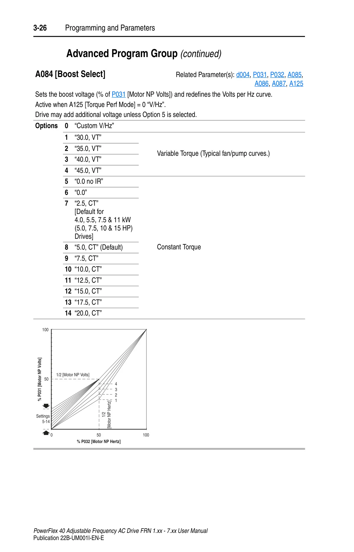
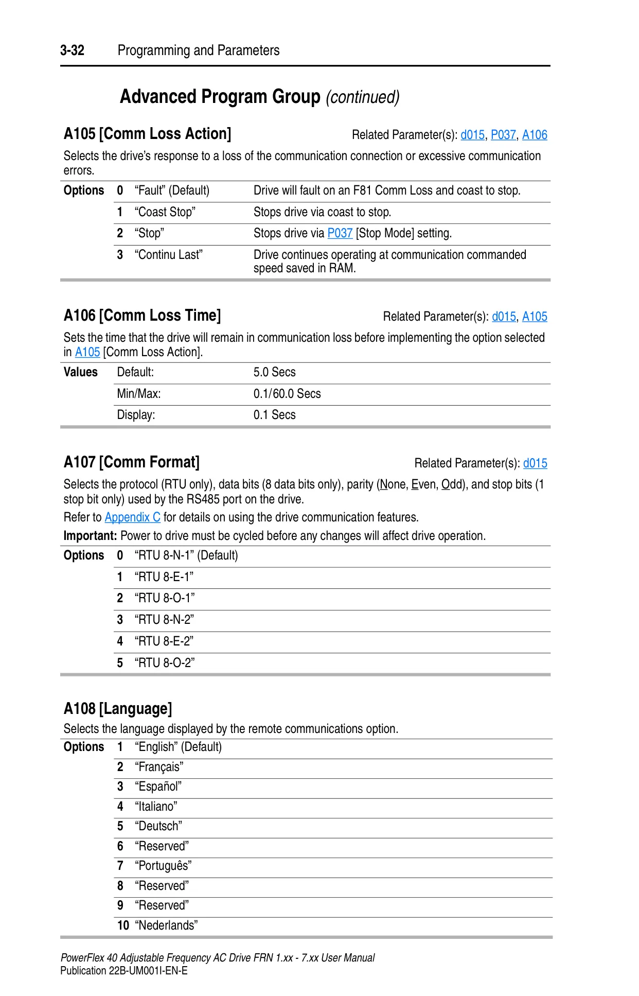
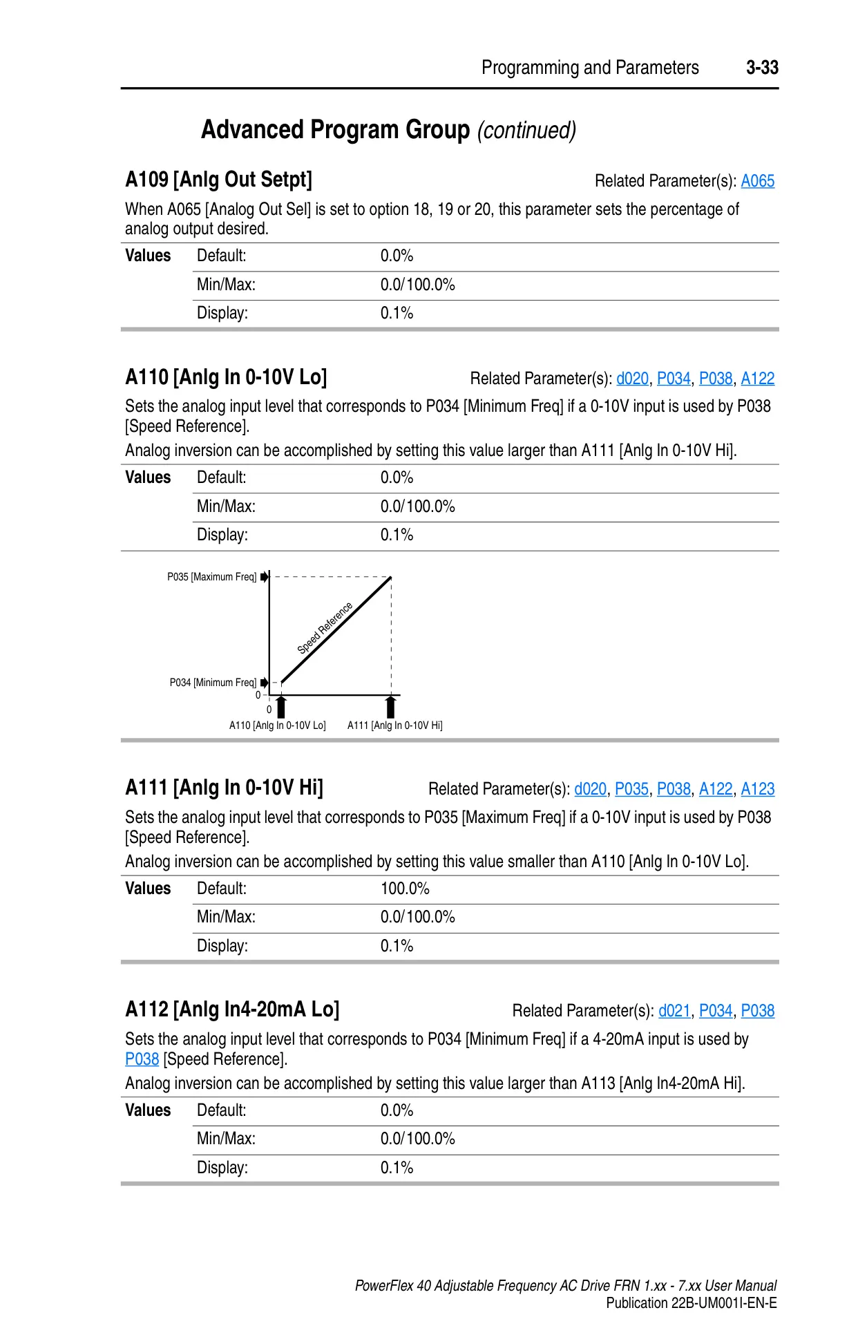
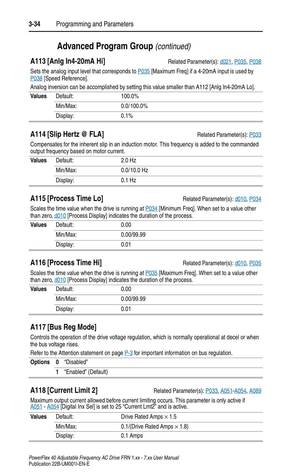
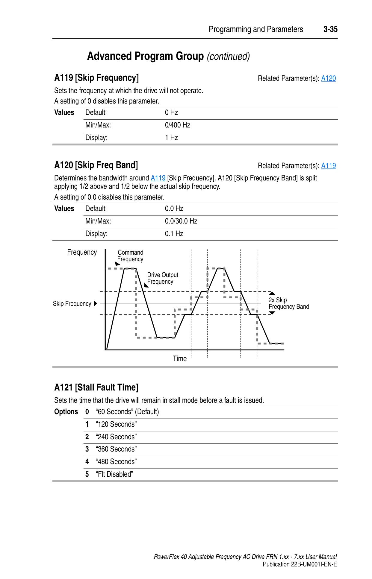
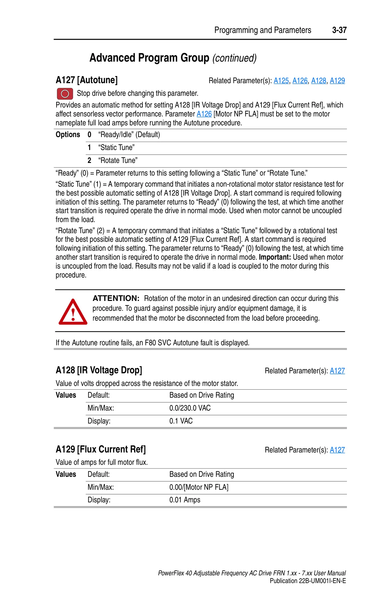
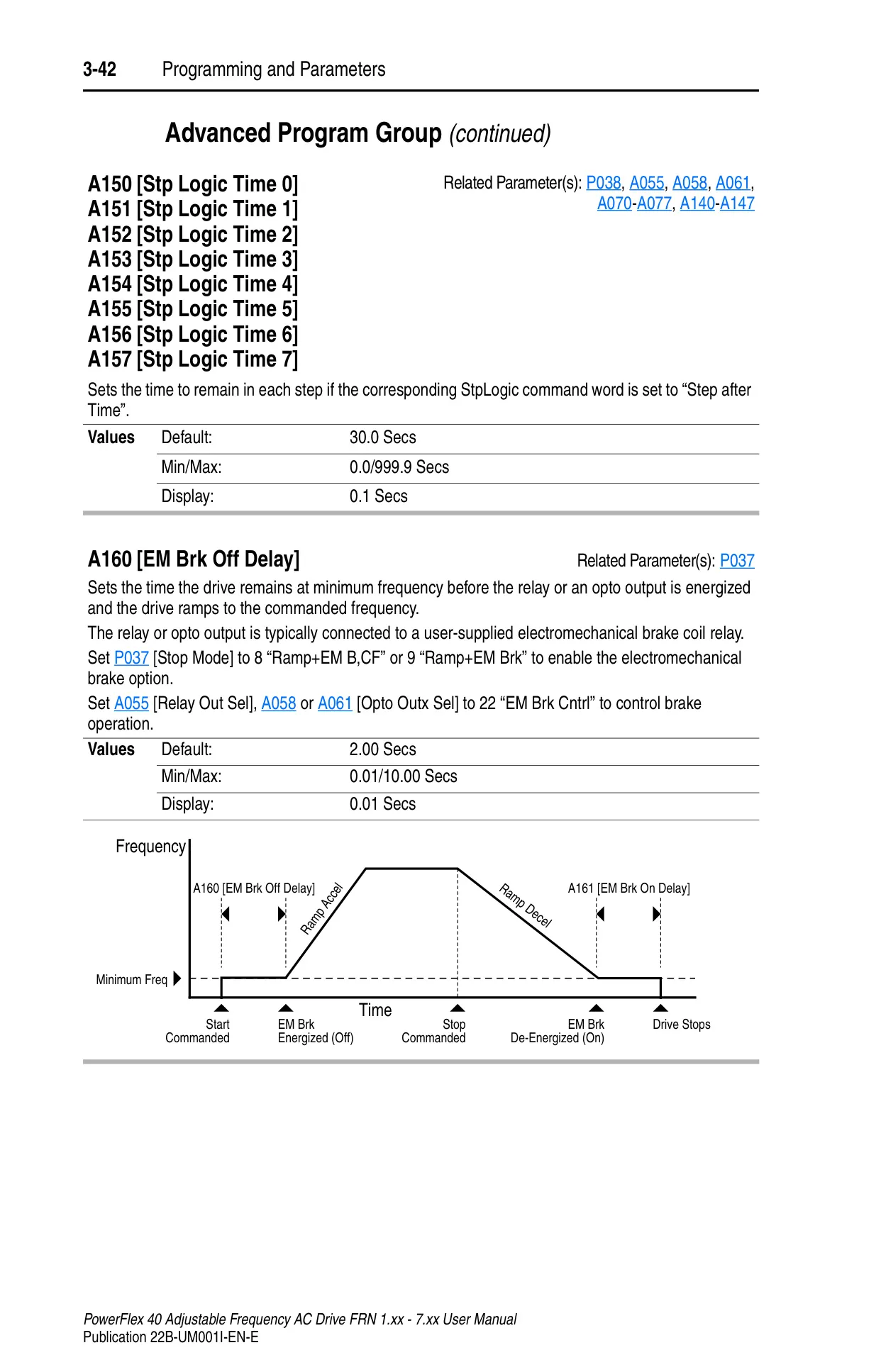
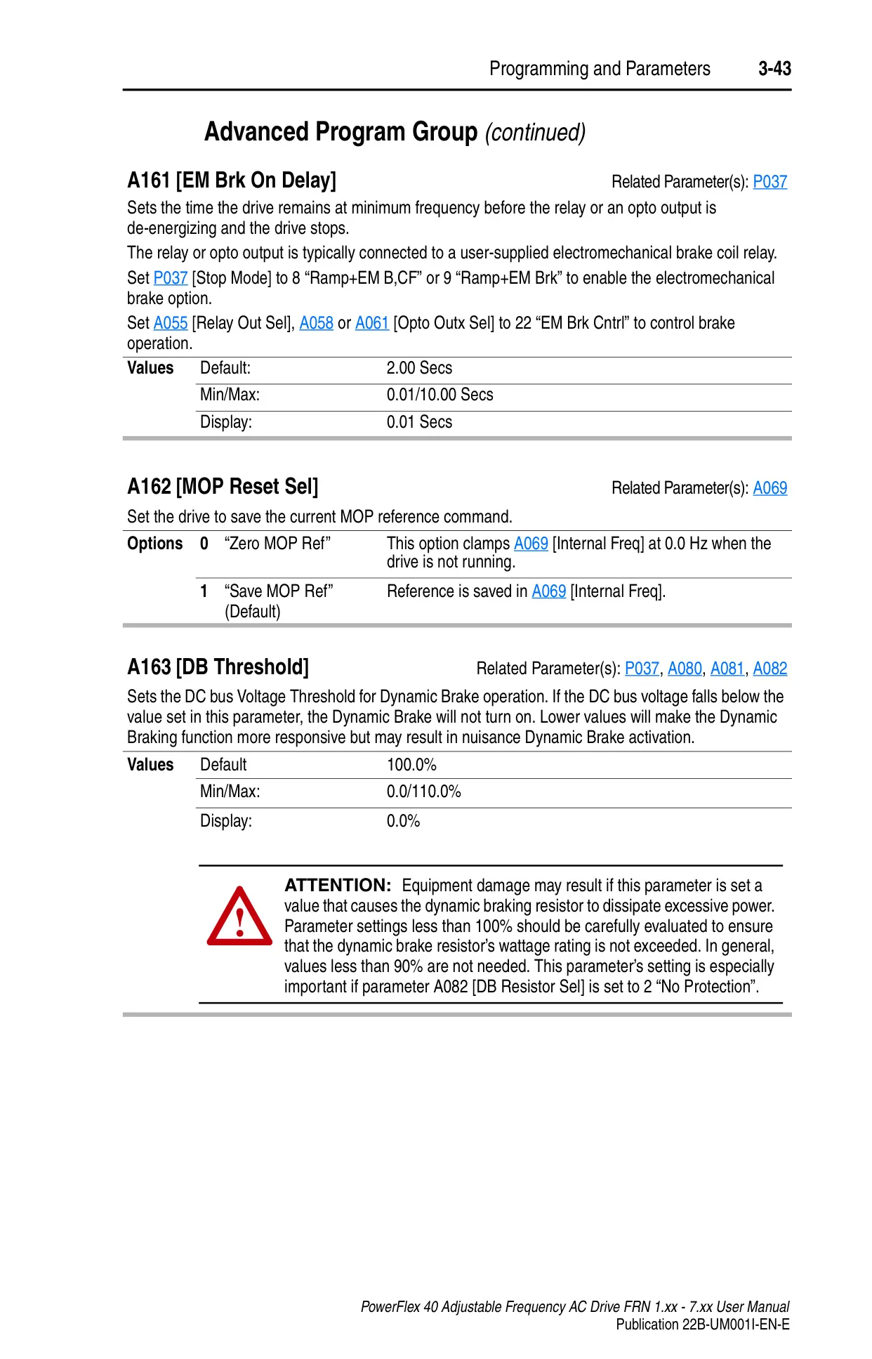
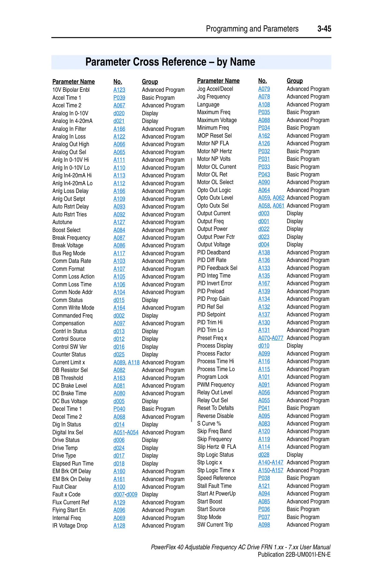
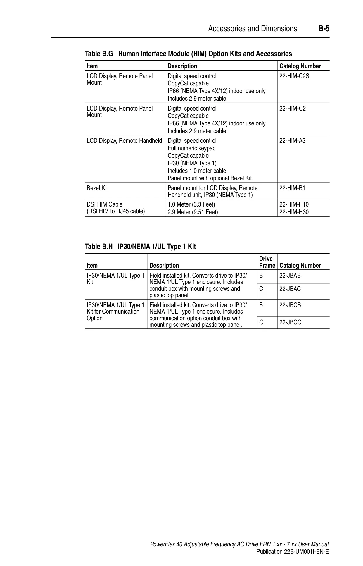
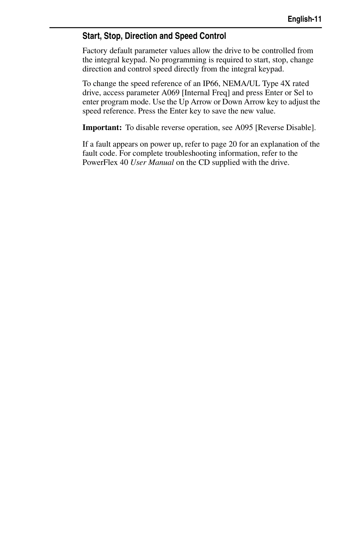
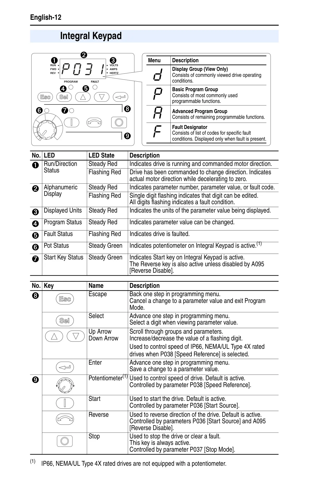
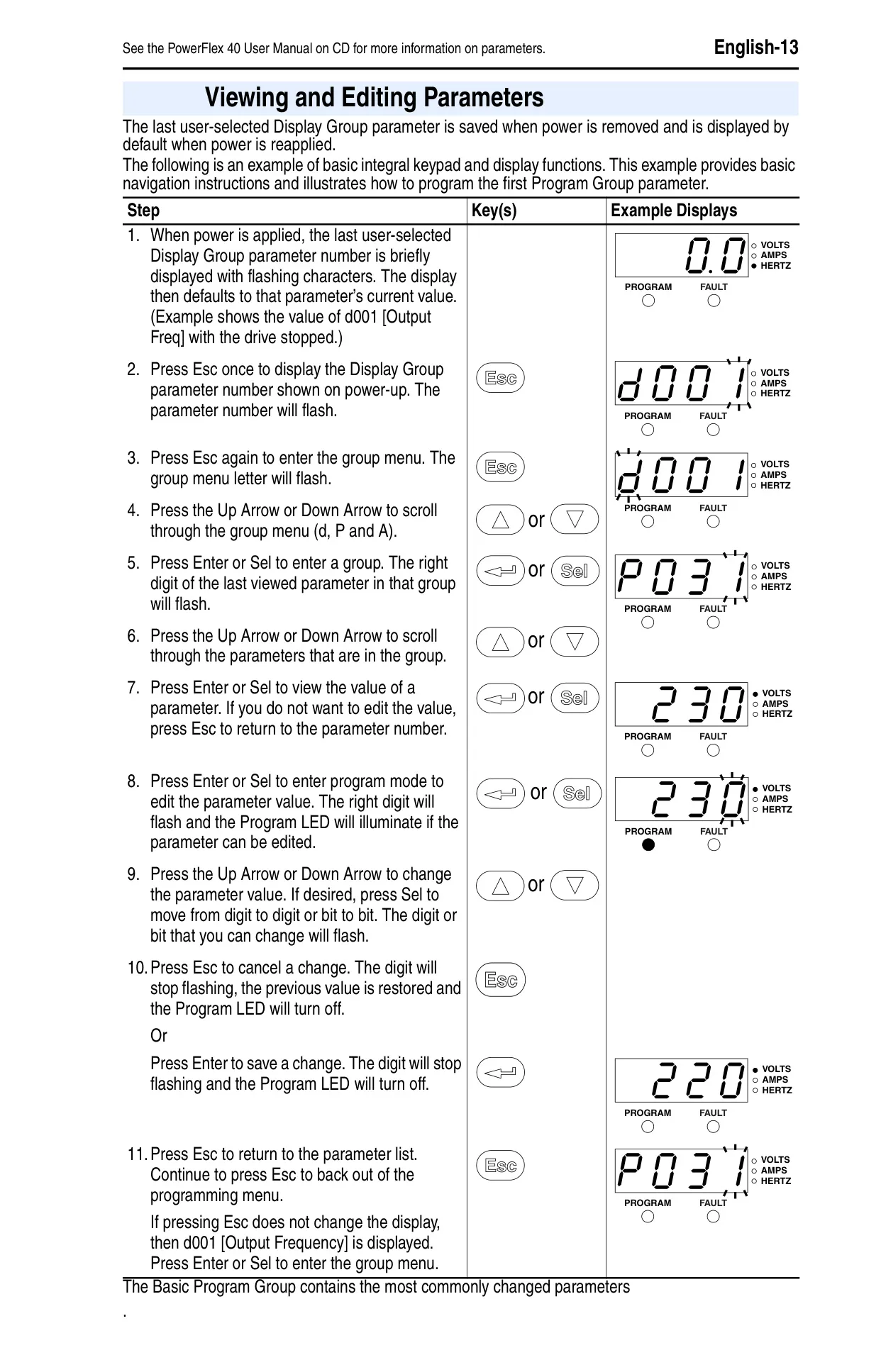
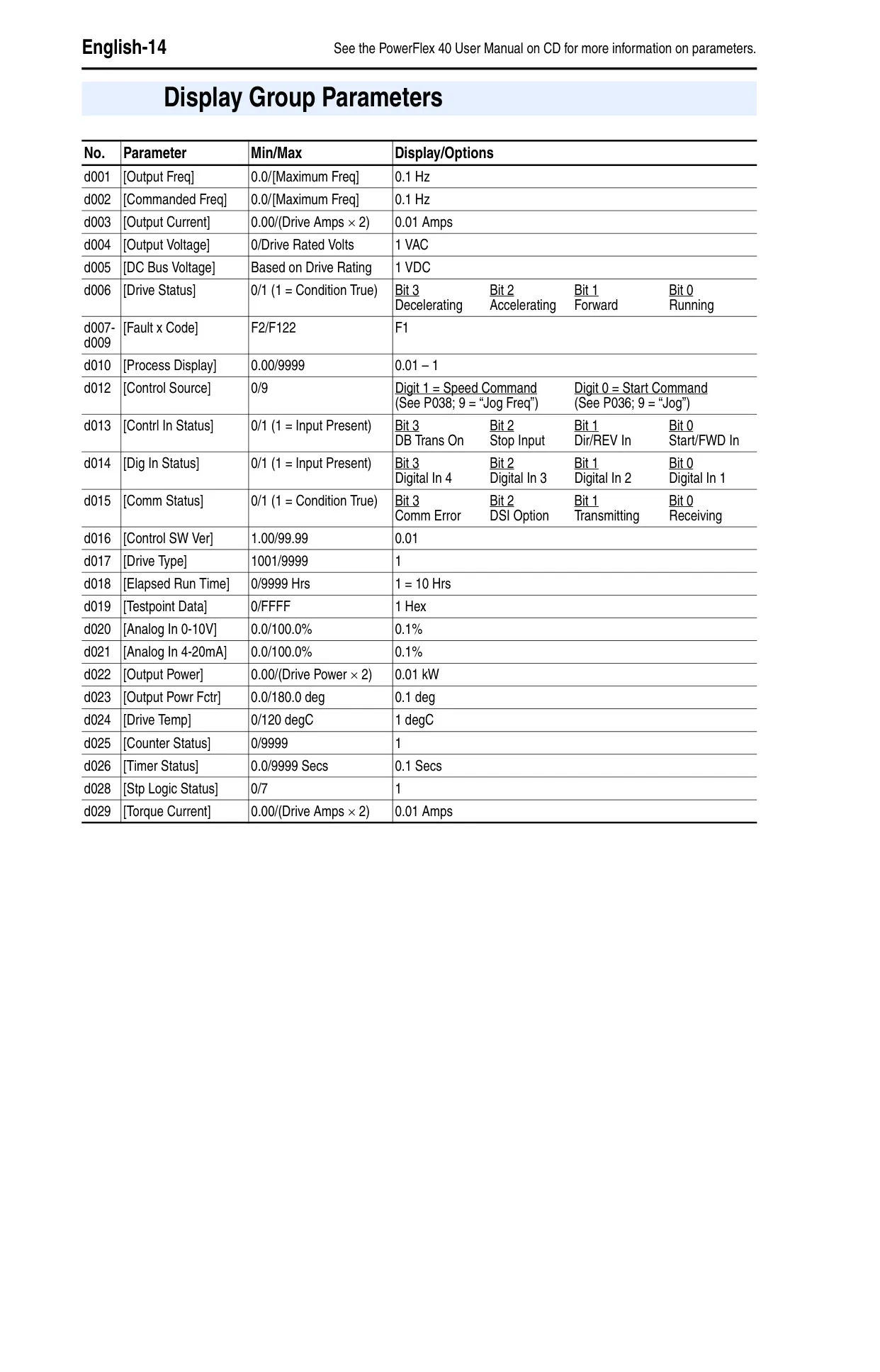
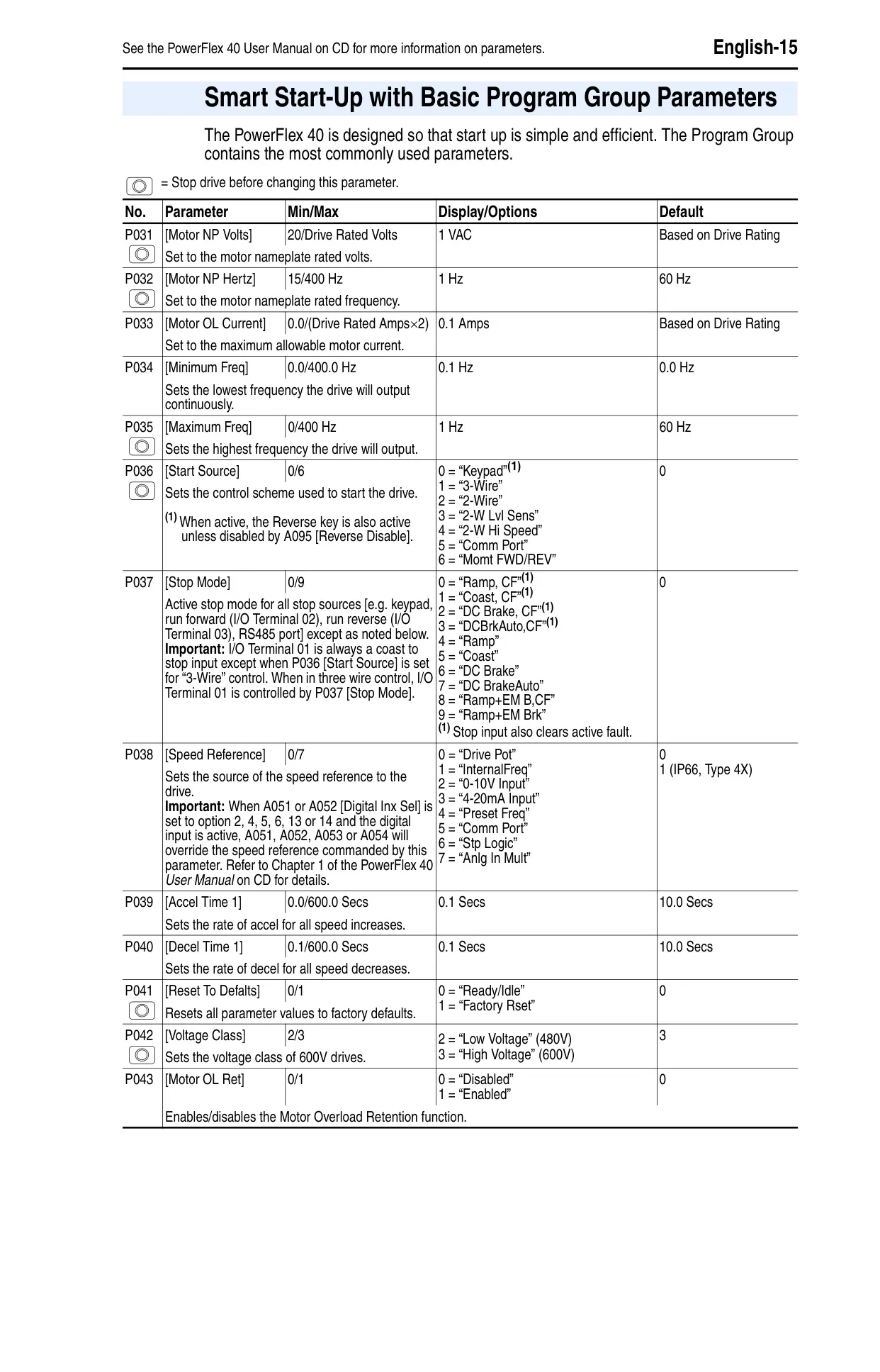
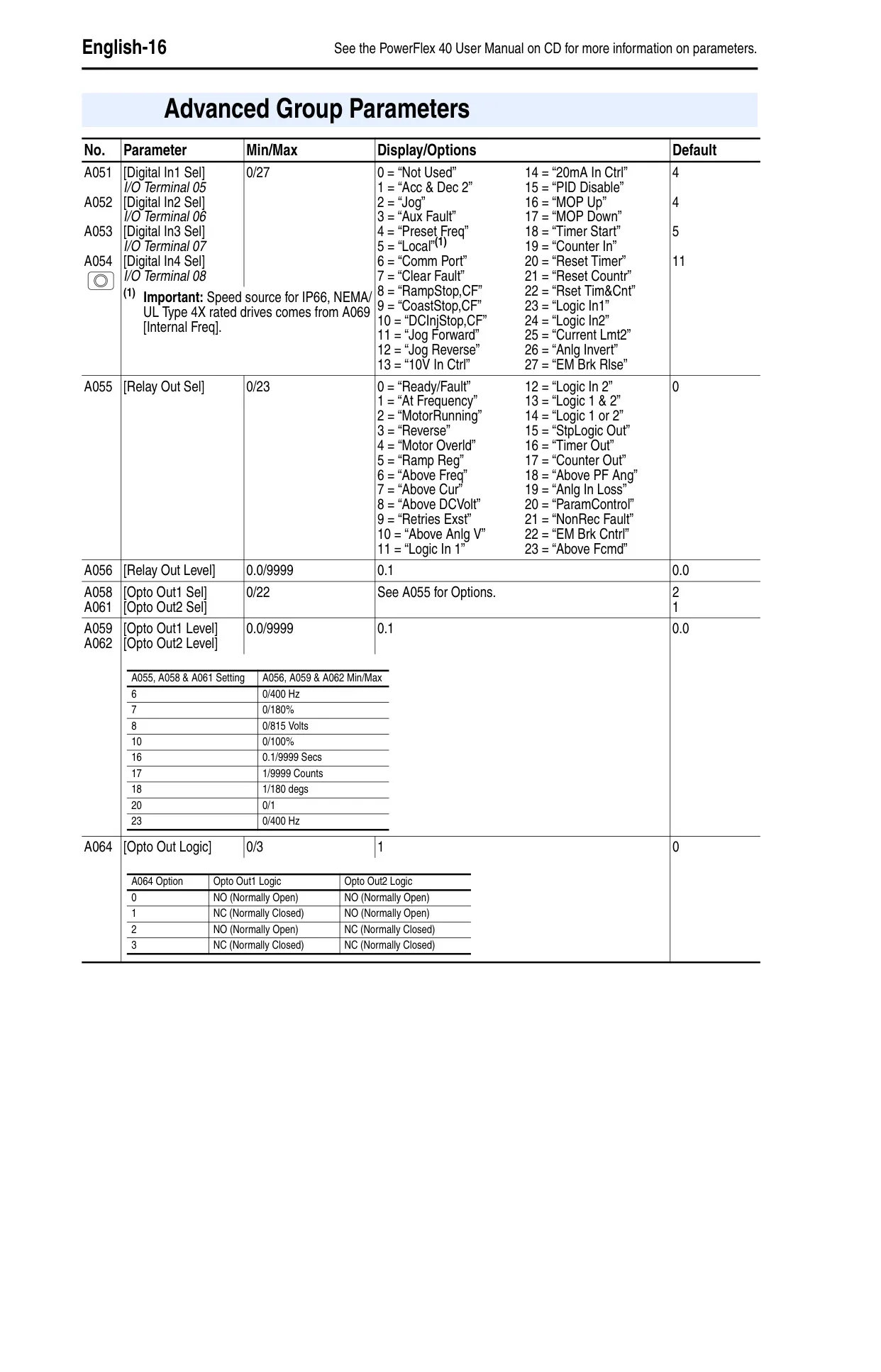
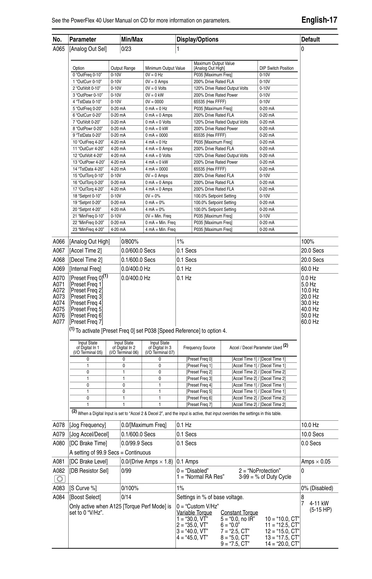
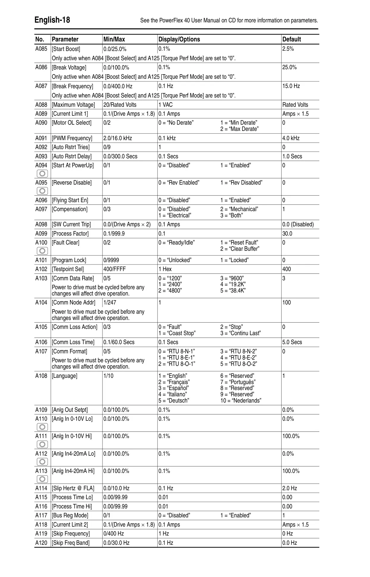
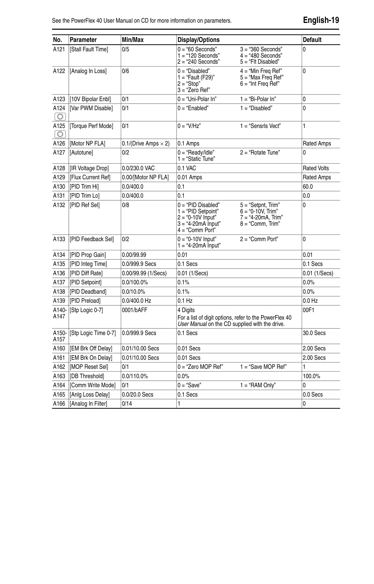
The PowerFlex 40 features an integral keypad for direct start-up, stopping, direction changes, and speed control, or these can be managed via remote Human Interface Modules (HIMs). Programming is organized into Display, Basic Program, and Advanced Program groups, allowing users to view operating conditions and customize parameters. Parameters are categorized as ENUM, Numeric, or Bit, offering flexible configuration options for a wide range of applications.
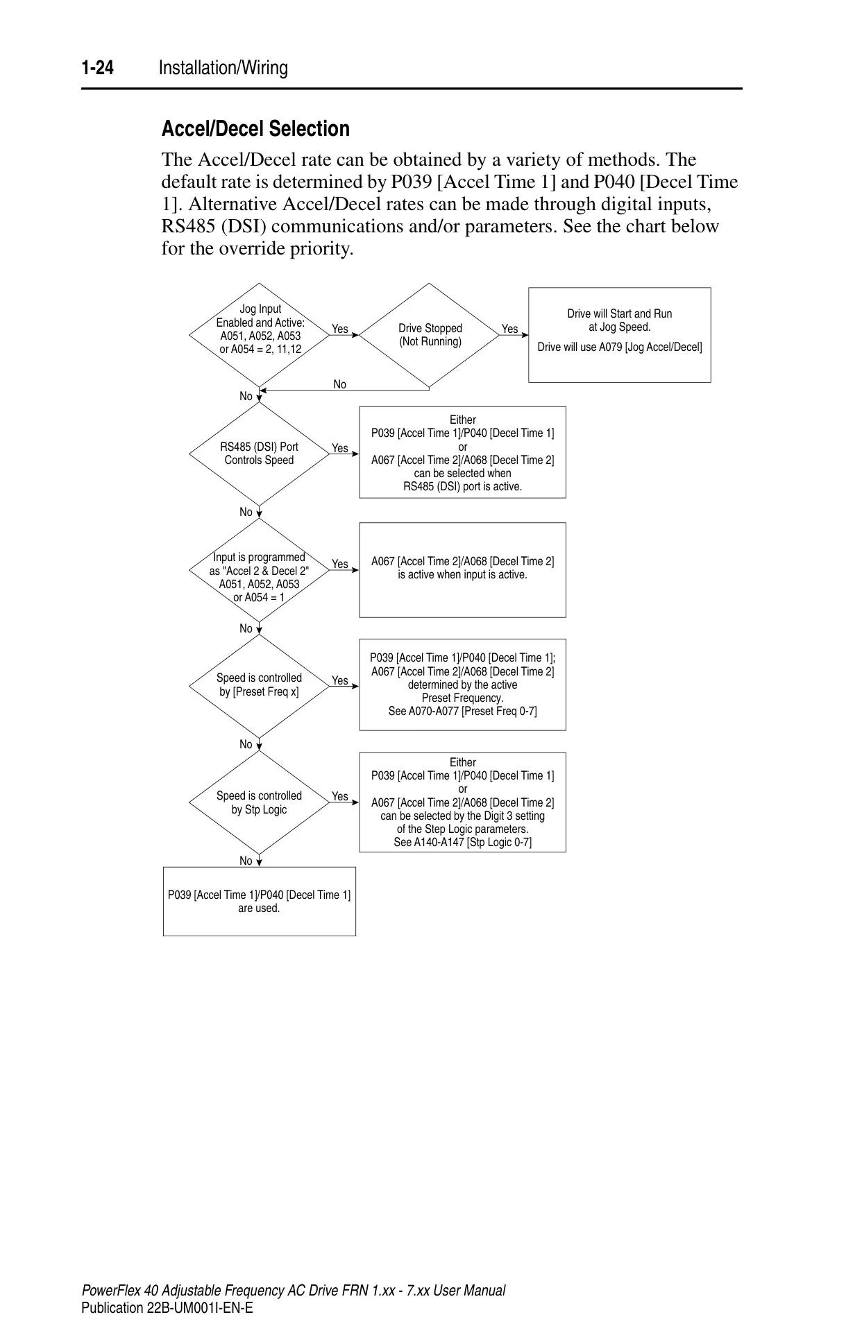
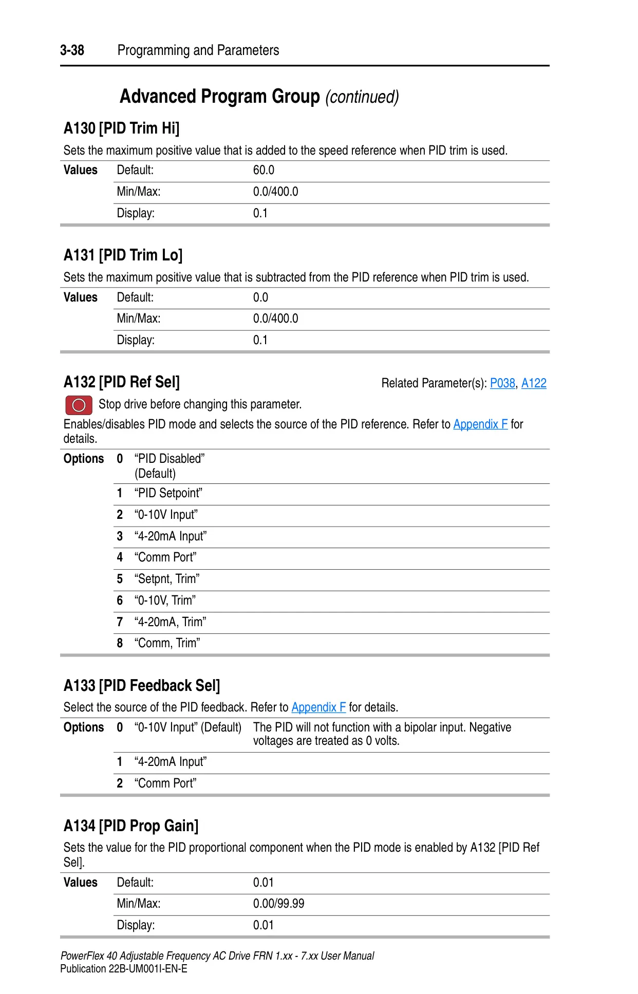
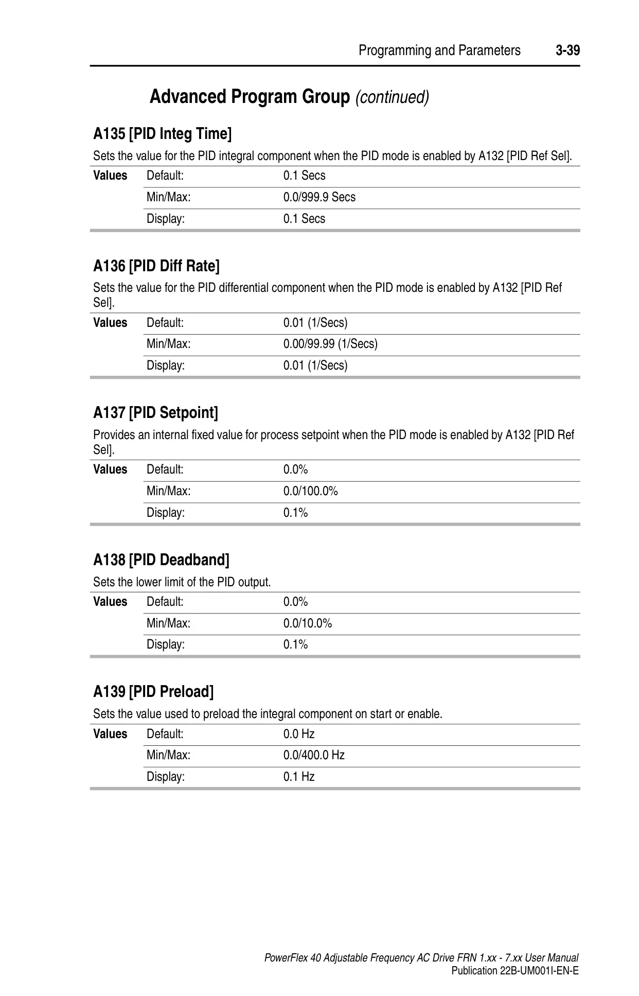
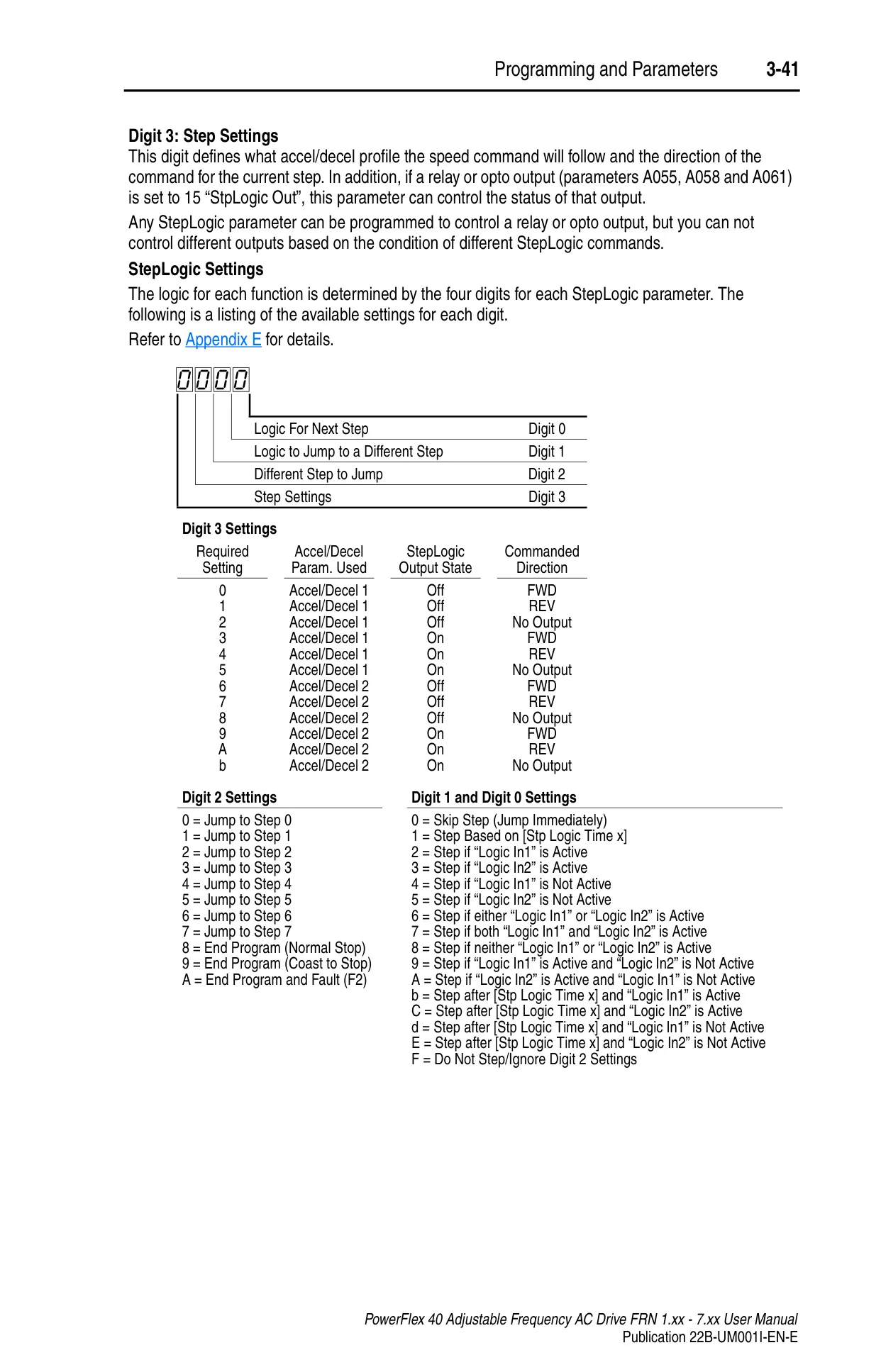
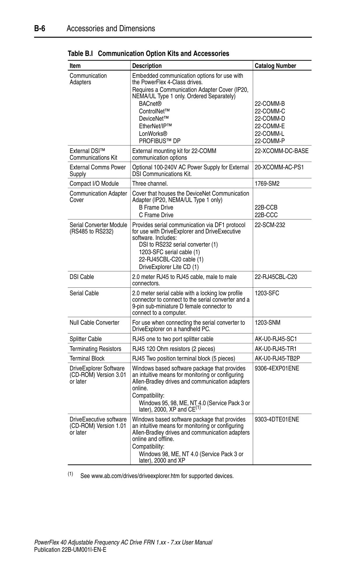
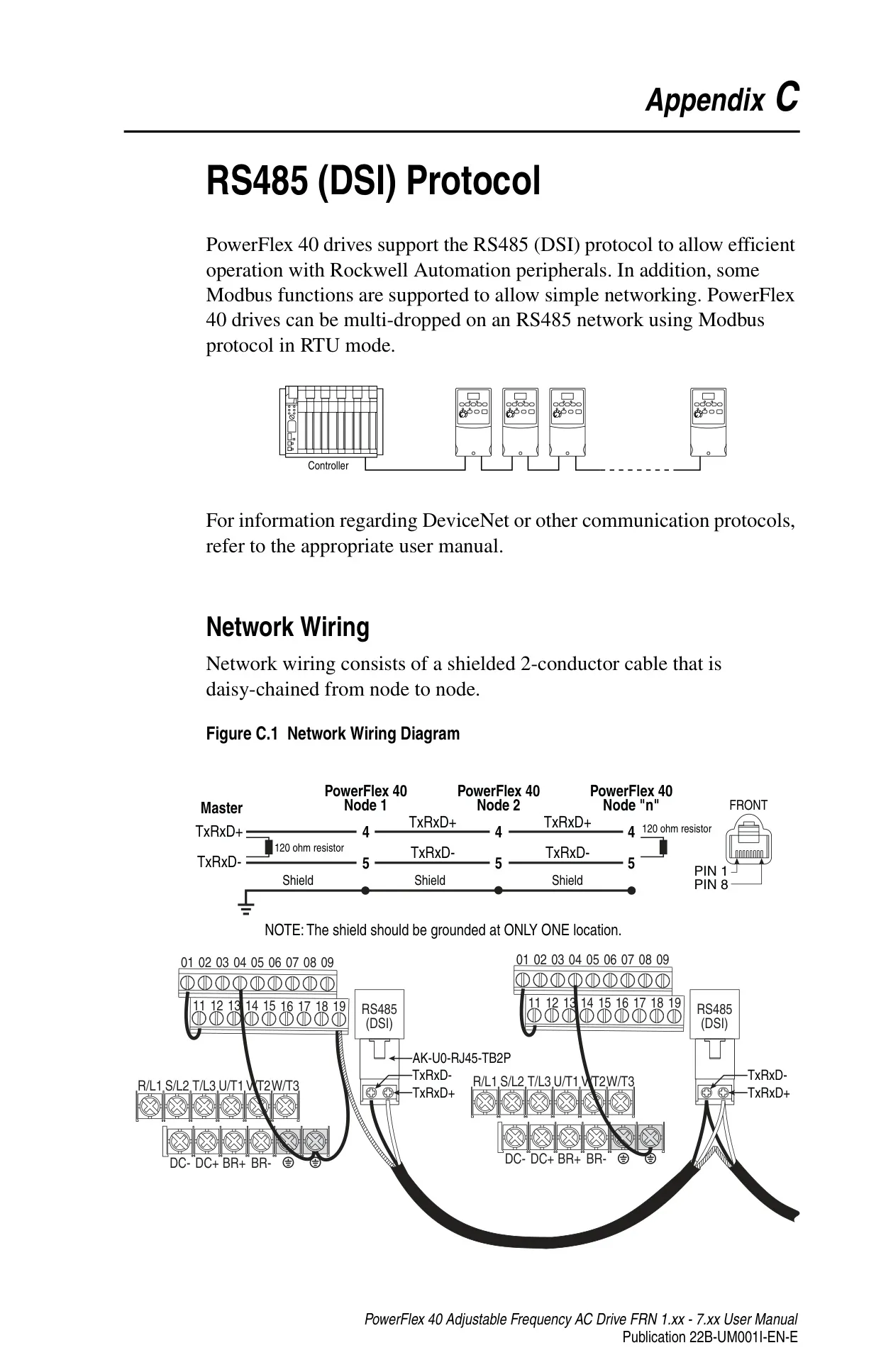
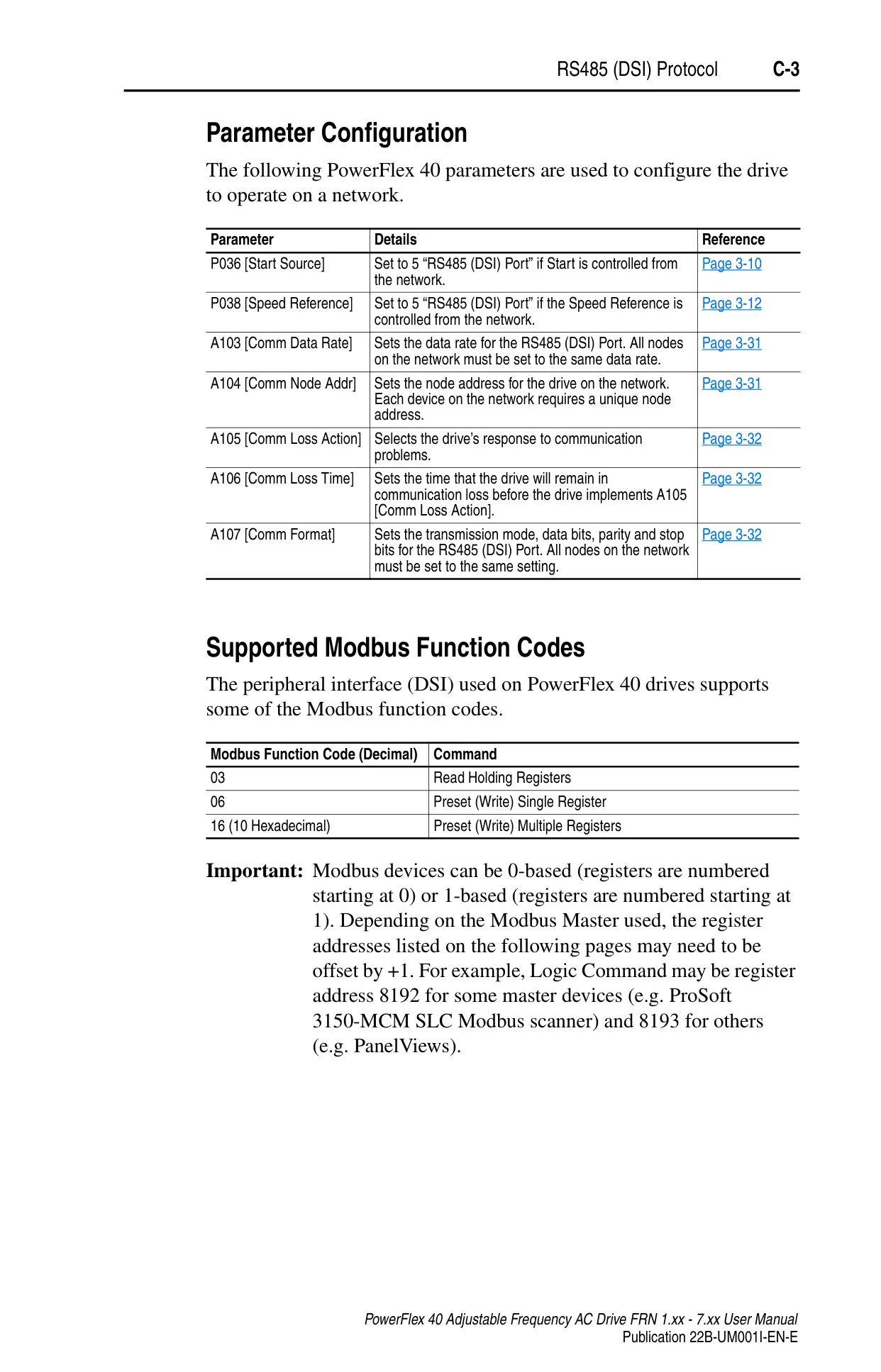
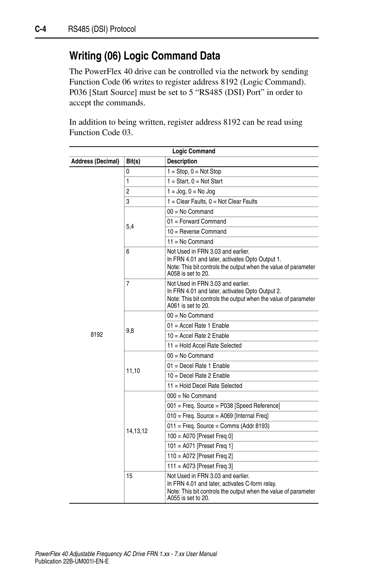
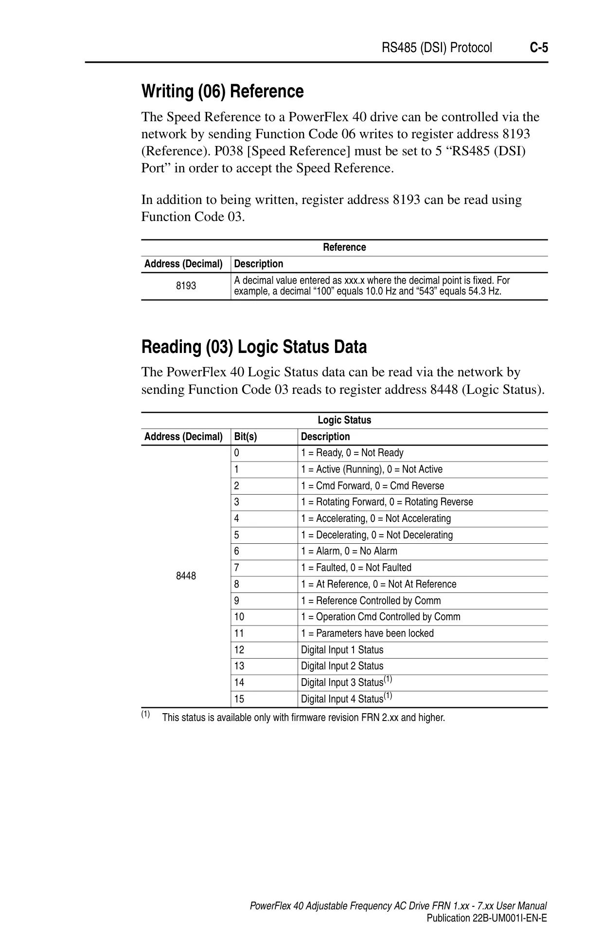
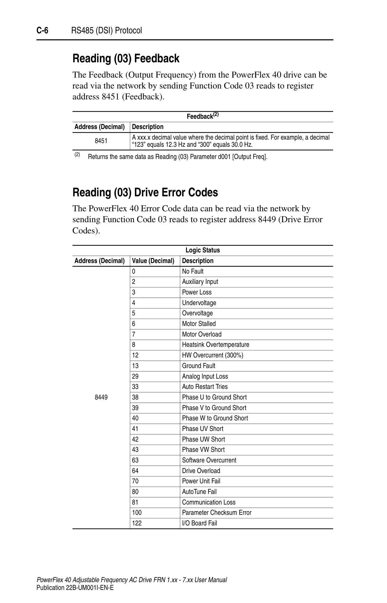
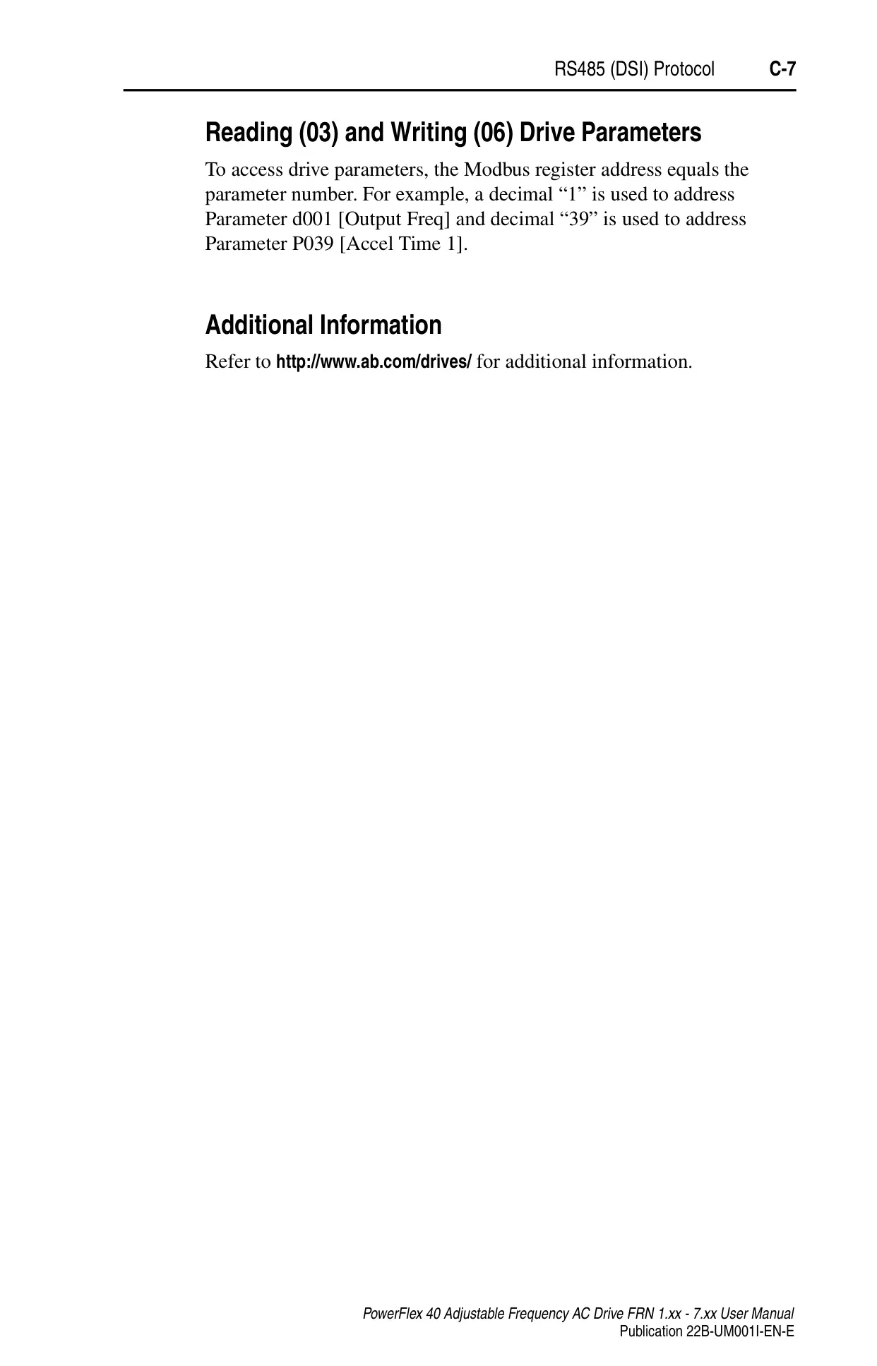
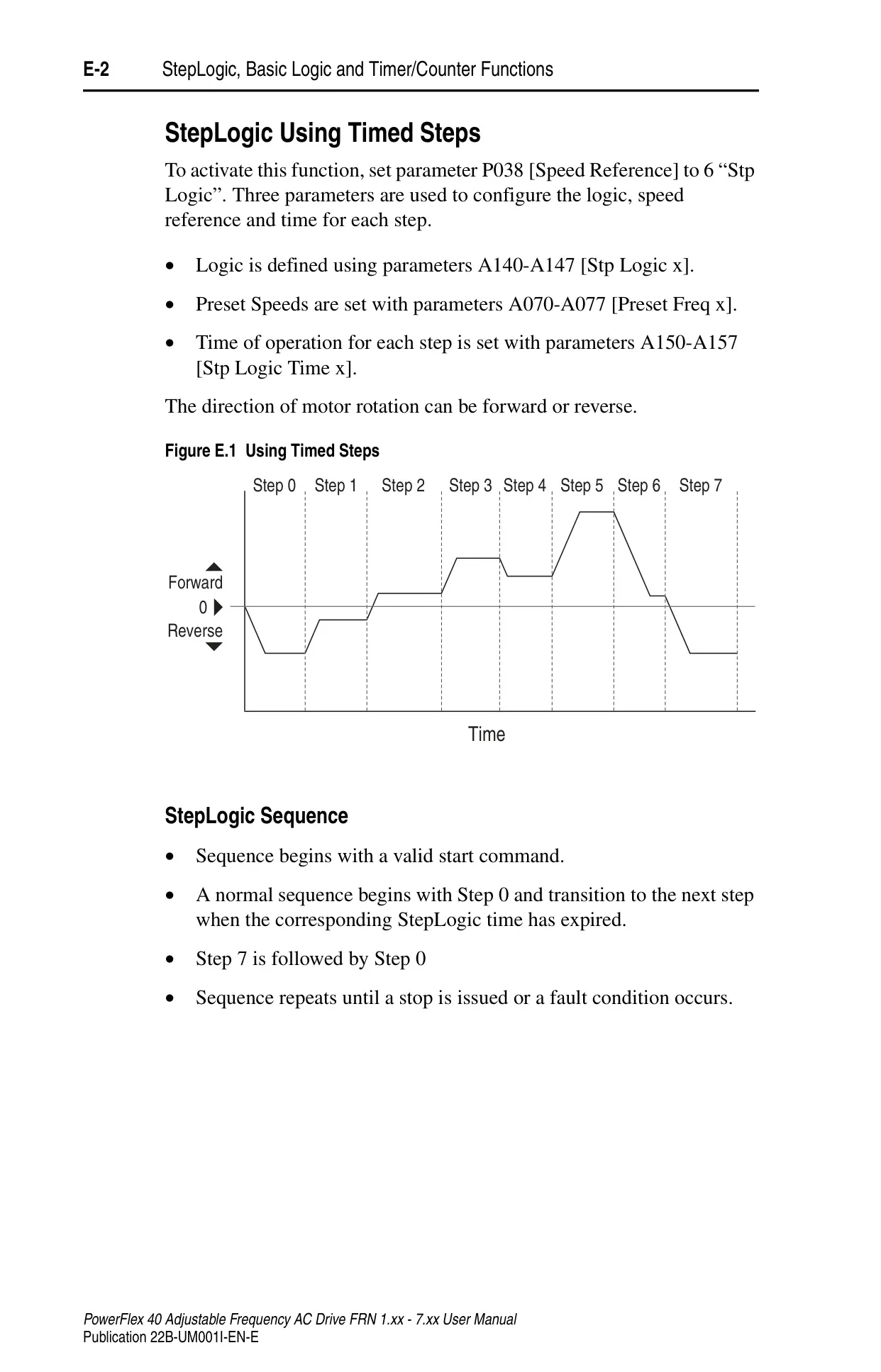
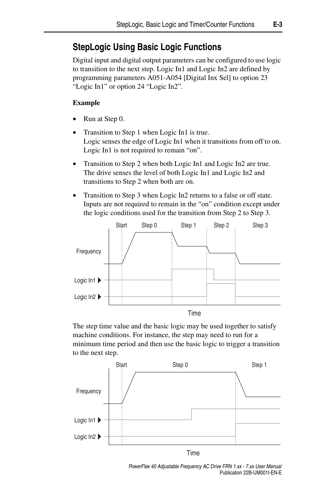
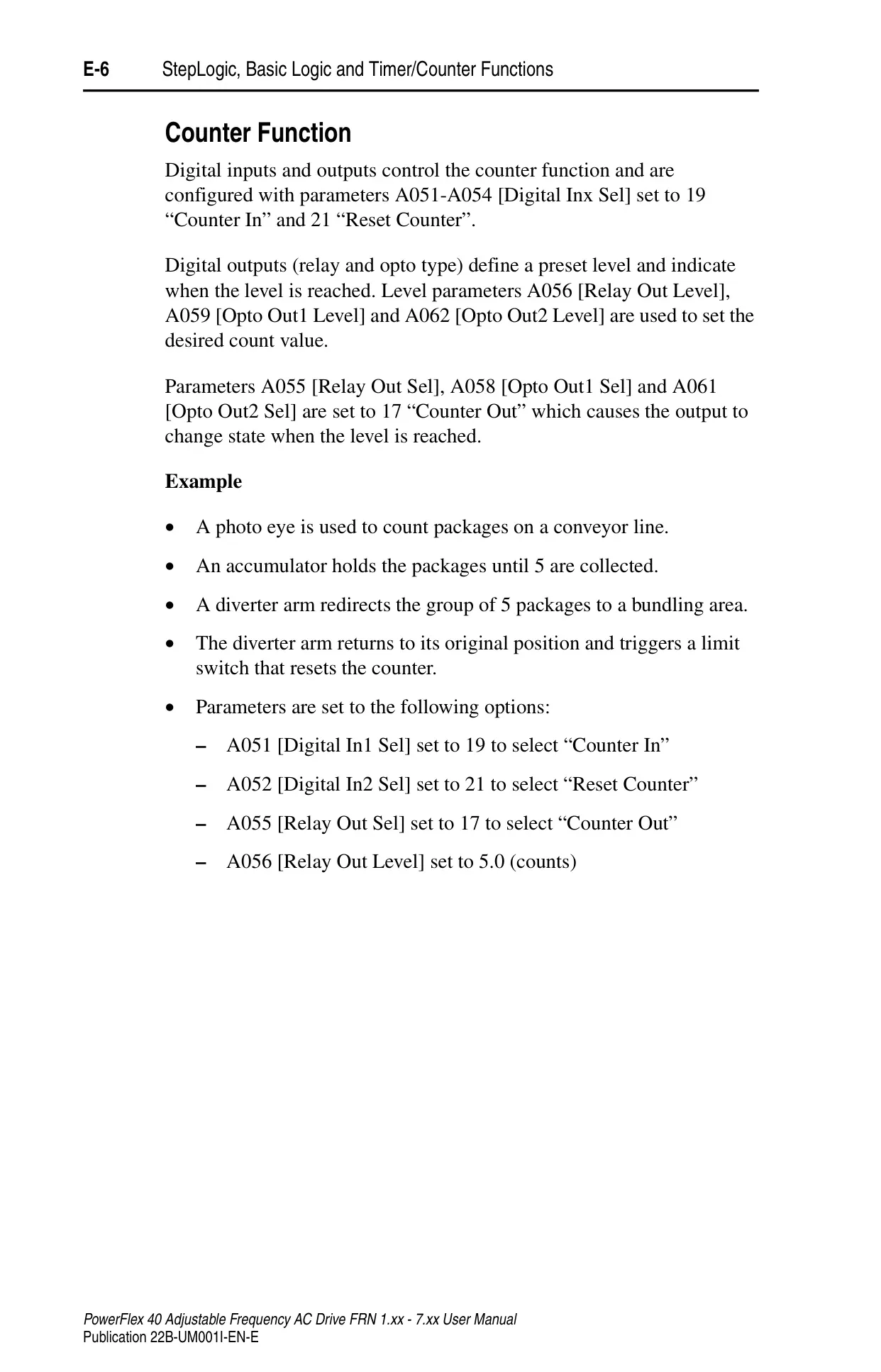
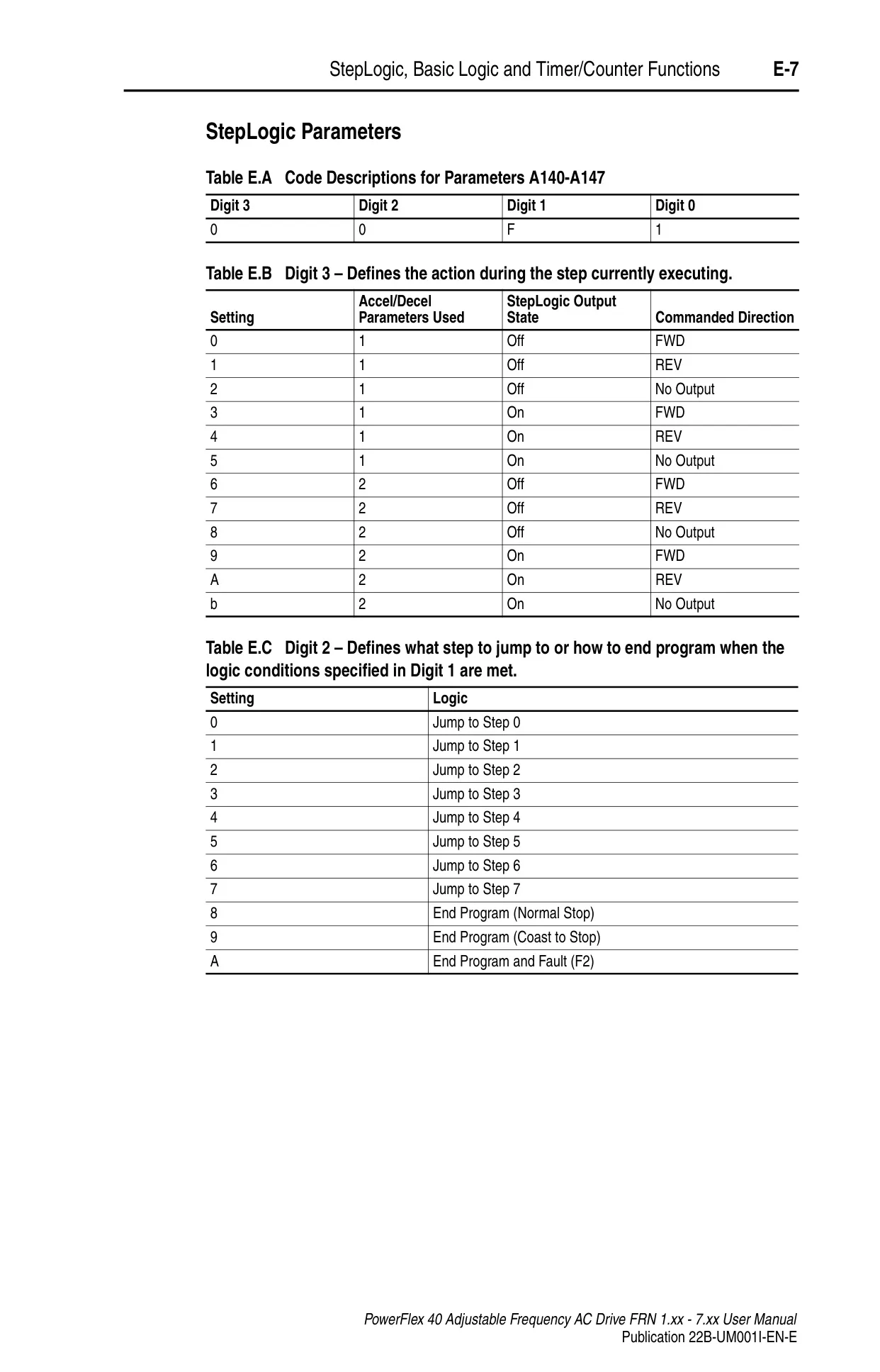
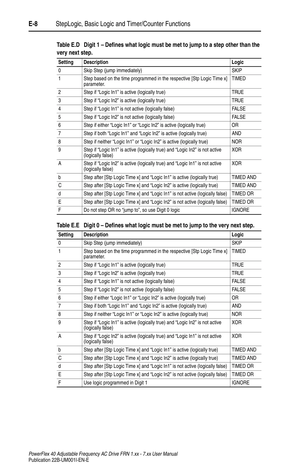
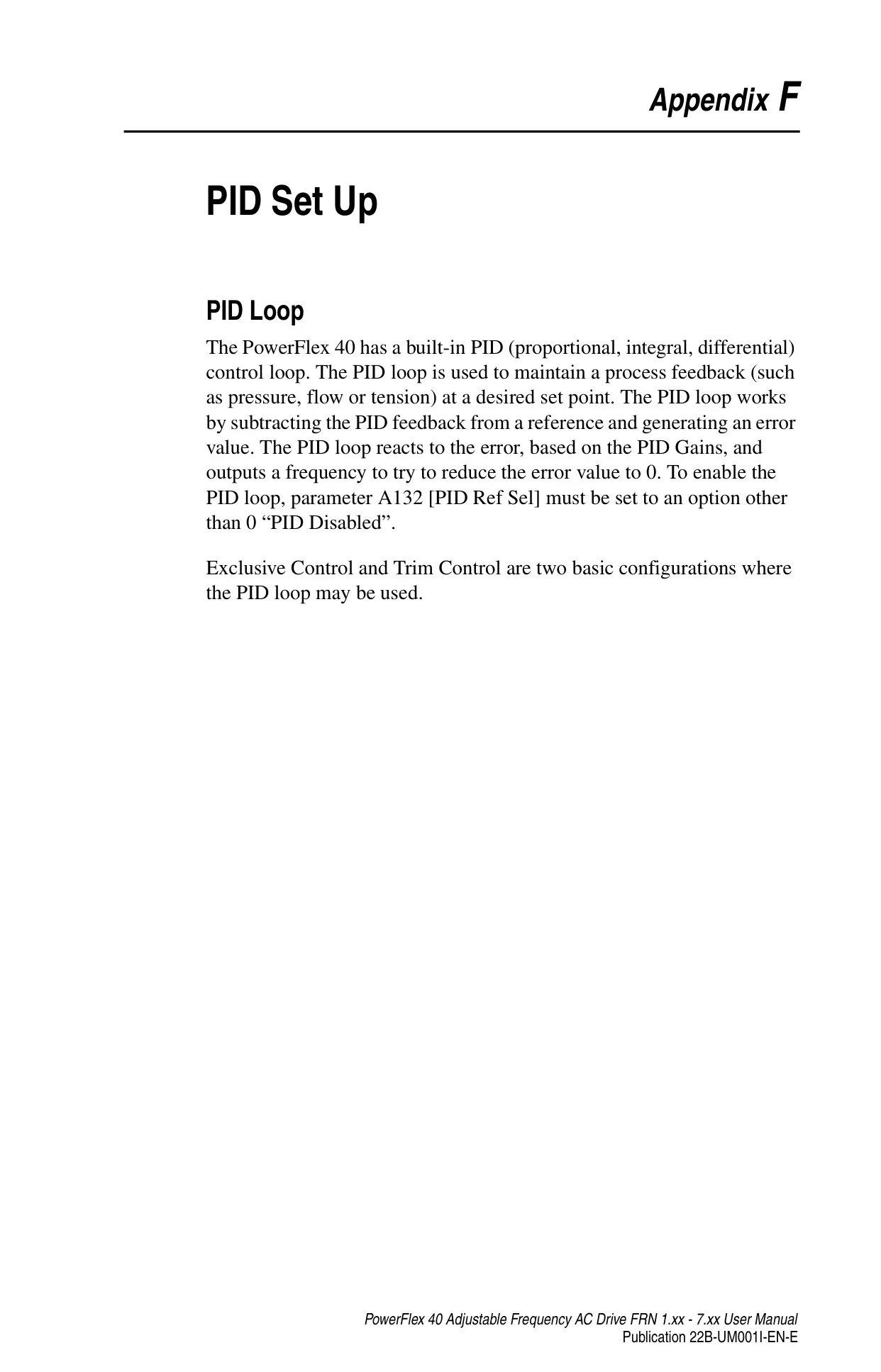
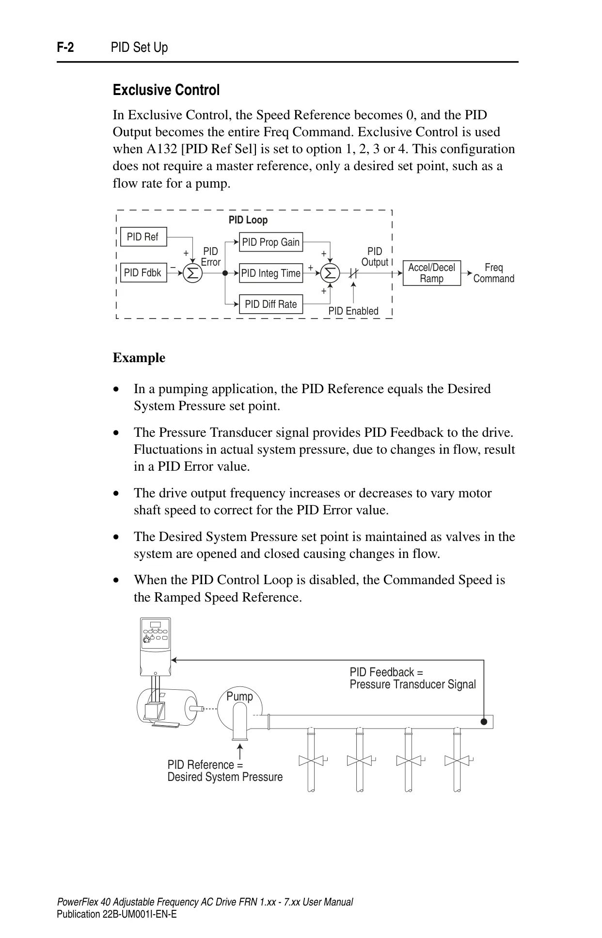
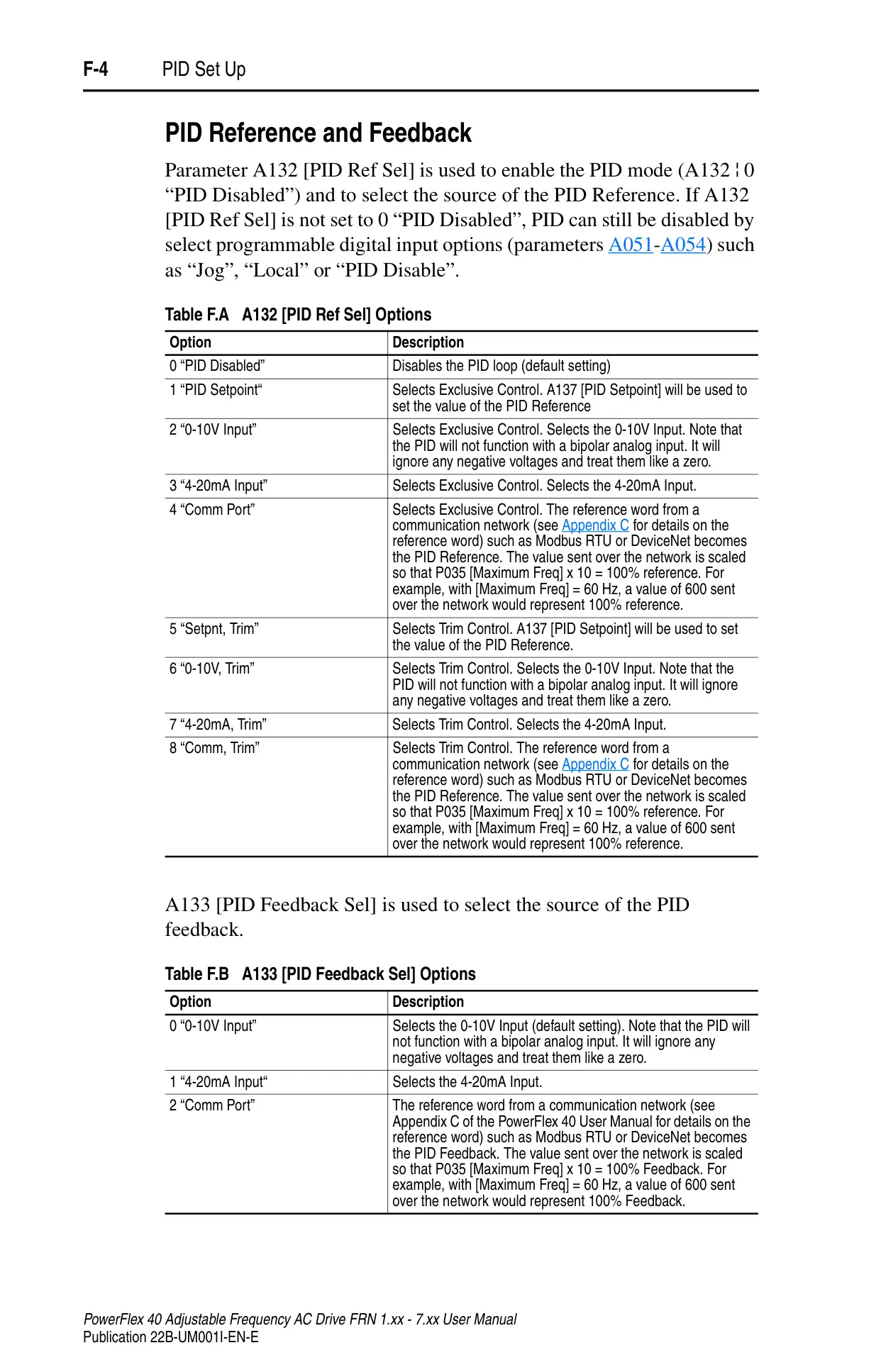
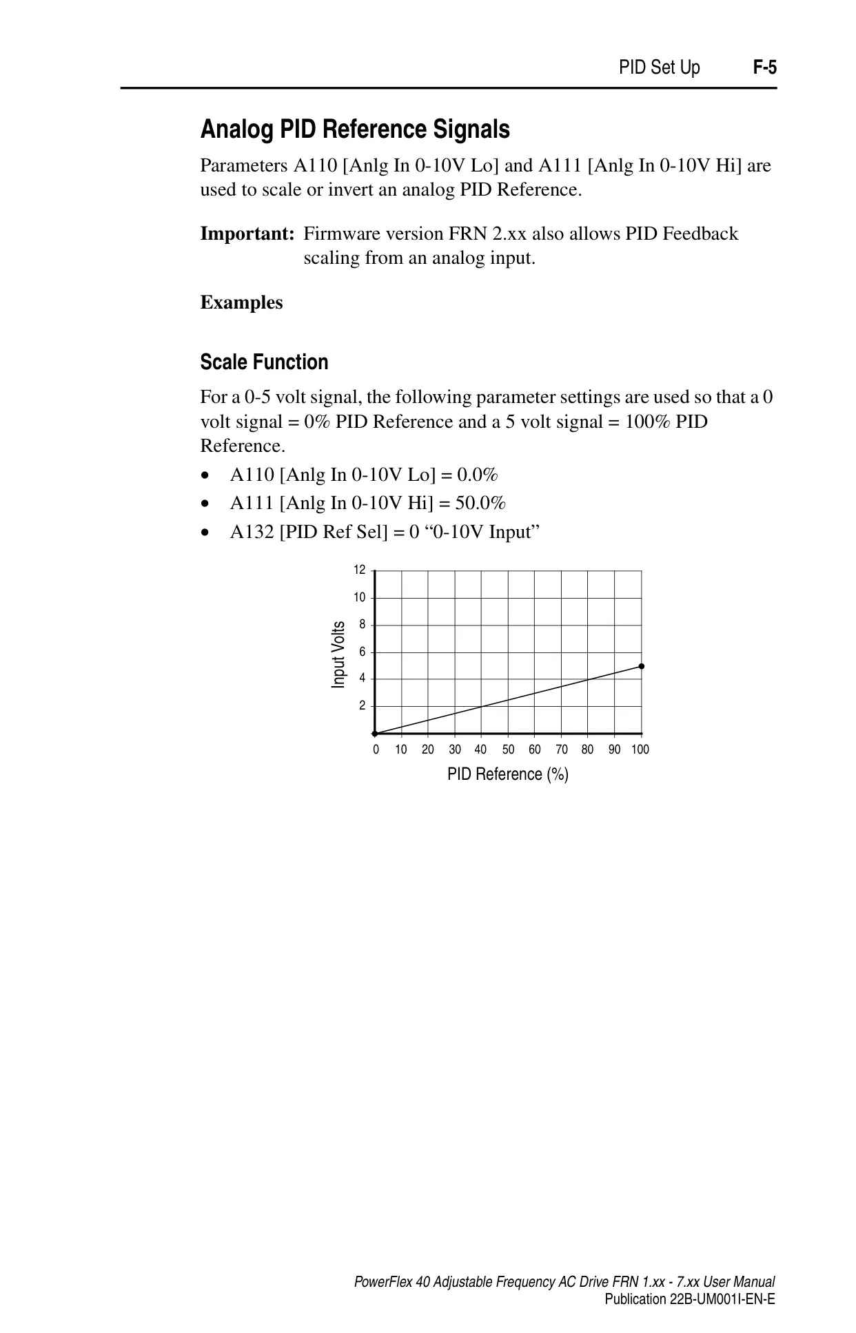
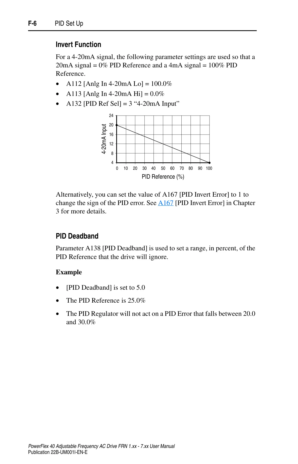
Beyond basic operation, the drive supports sophisticated control schemes like StepLogic™, enabling up to eight preset speeds with programmed logic based on digital inputs or timed intervals. A built-in PID control loop allows for maintaining process feedback at a desired setpoint in either exclusive or trim control modes. Communication capabilities are robust, utilizing the RS485 (DSI) protocol with Modbus function code support for efficient networking and control through external devices or software like DriveExplorer and DriveExecutive.
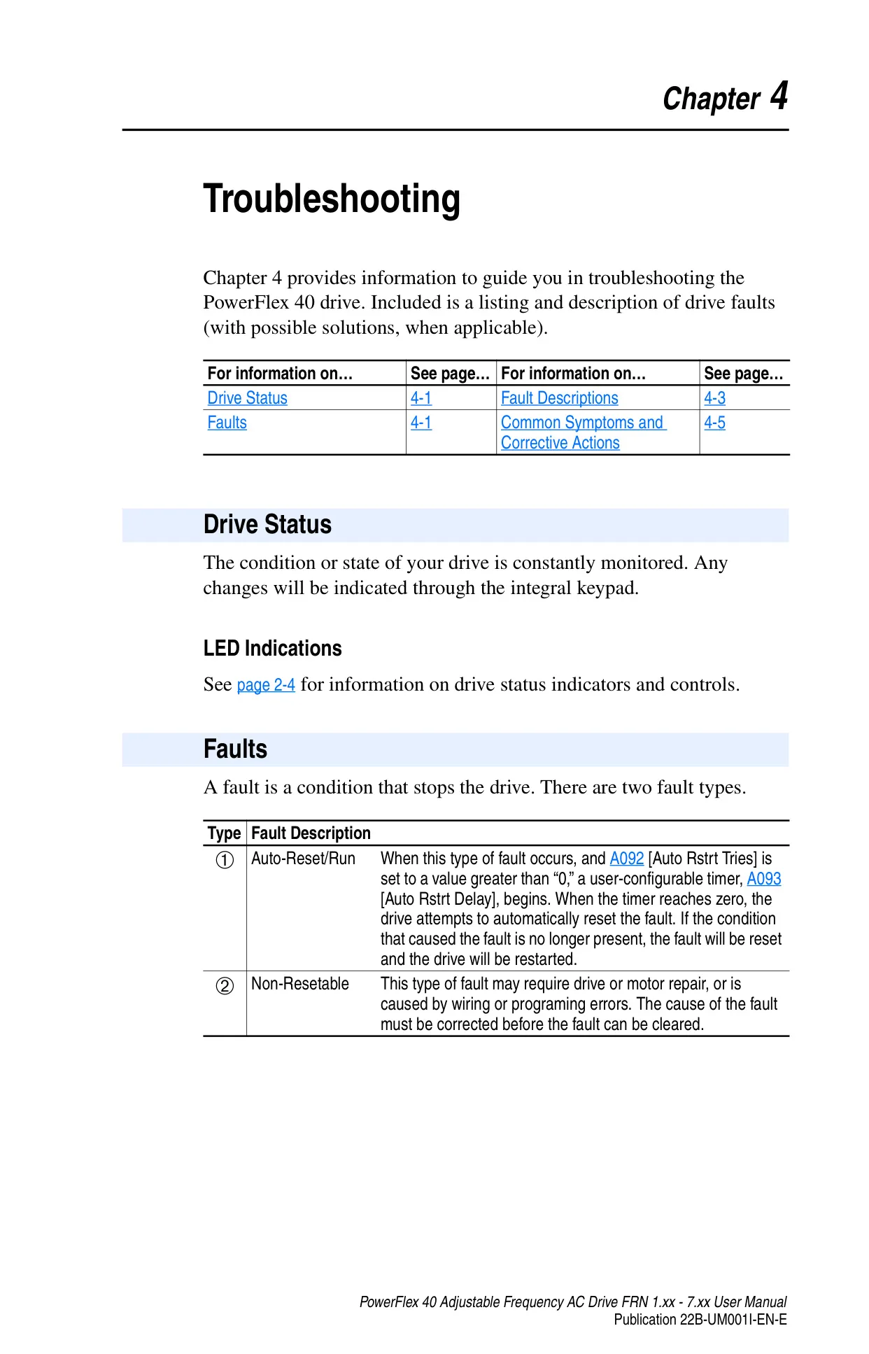
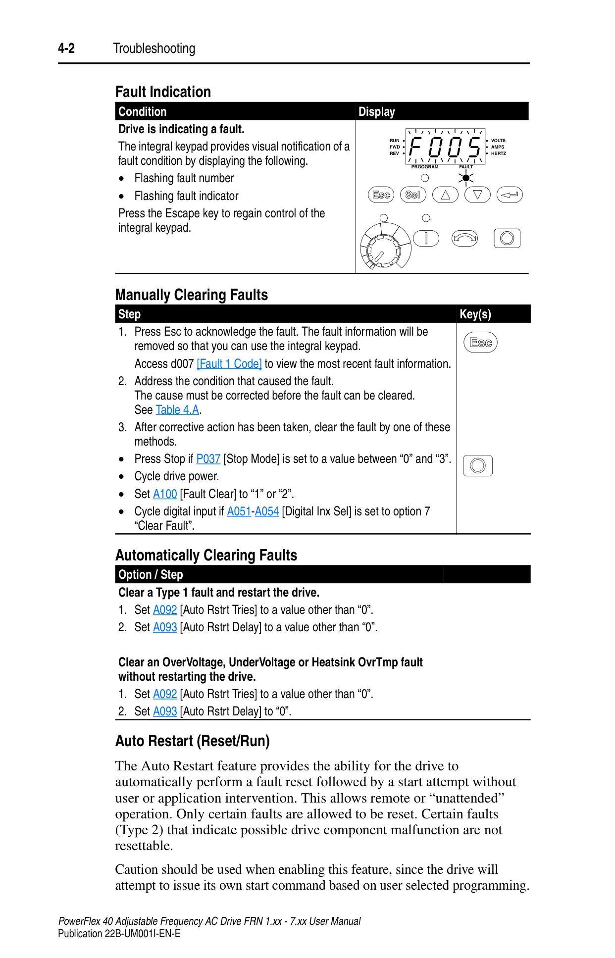
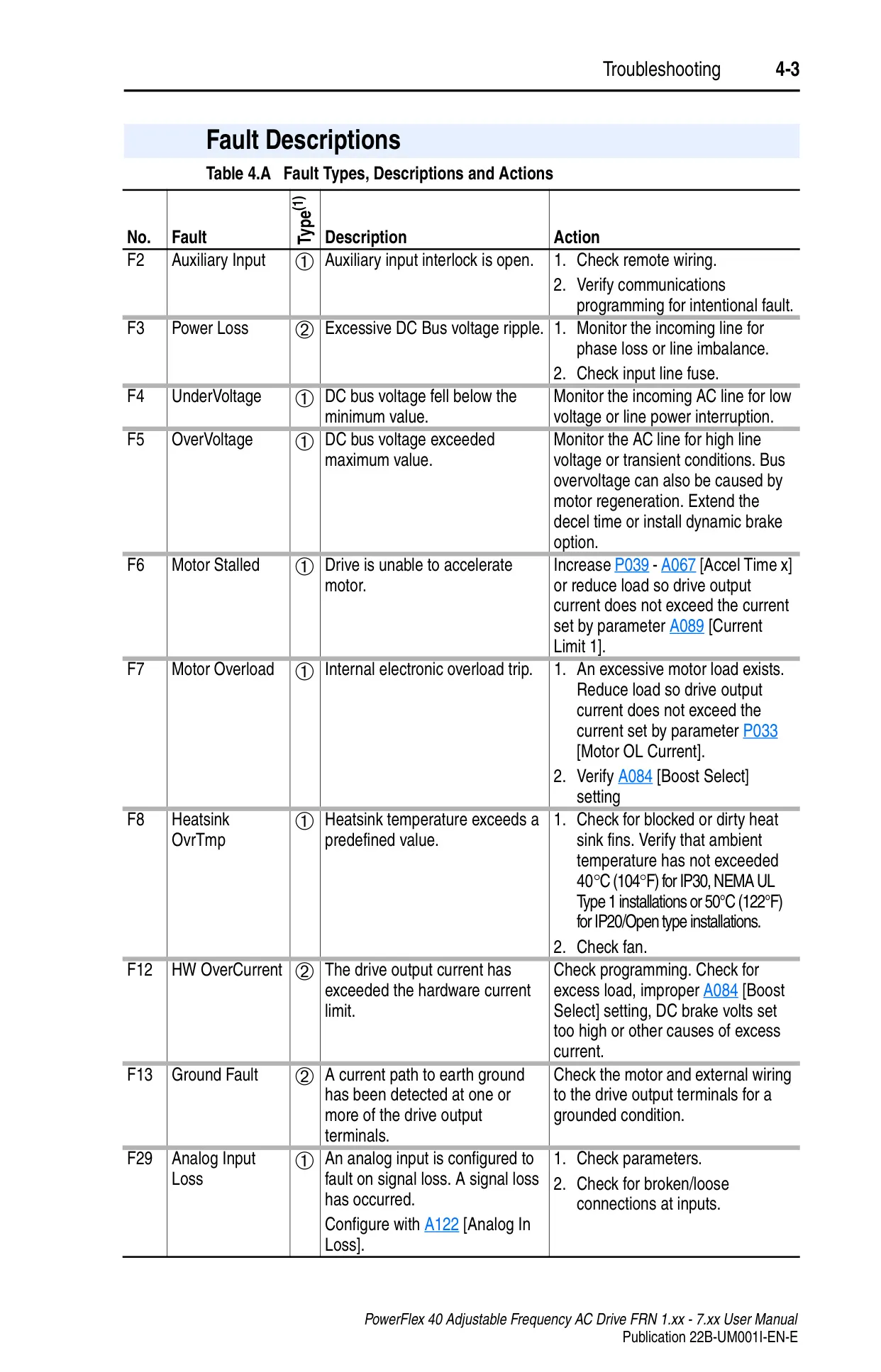
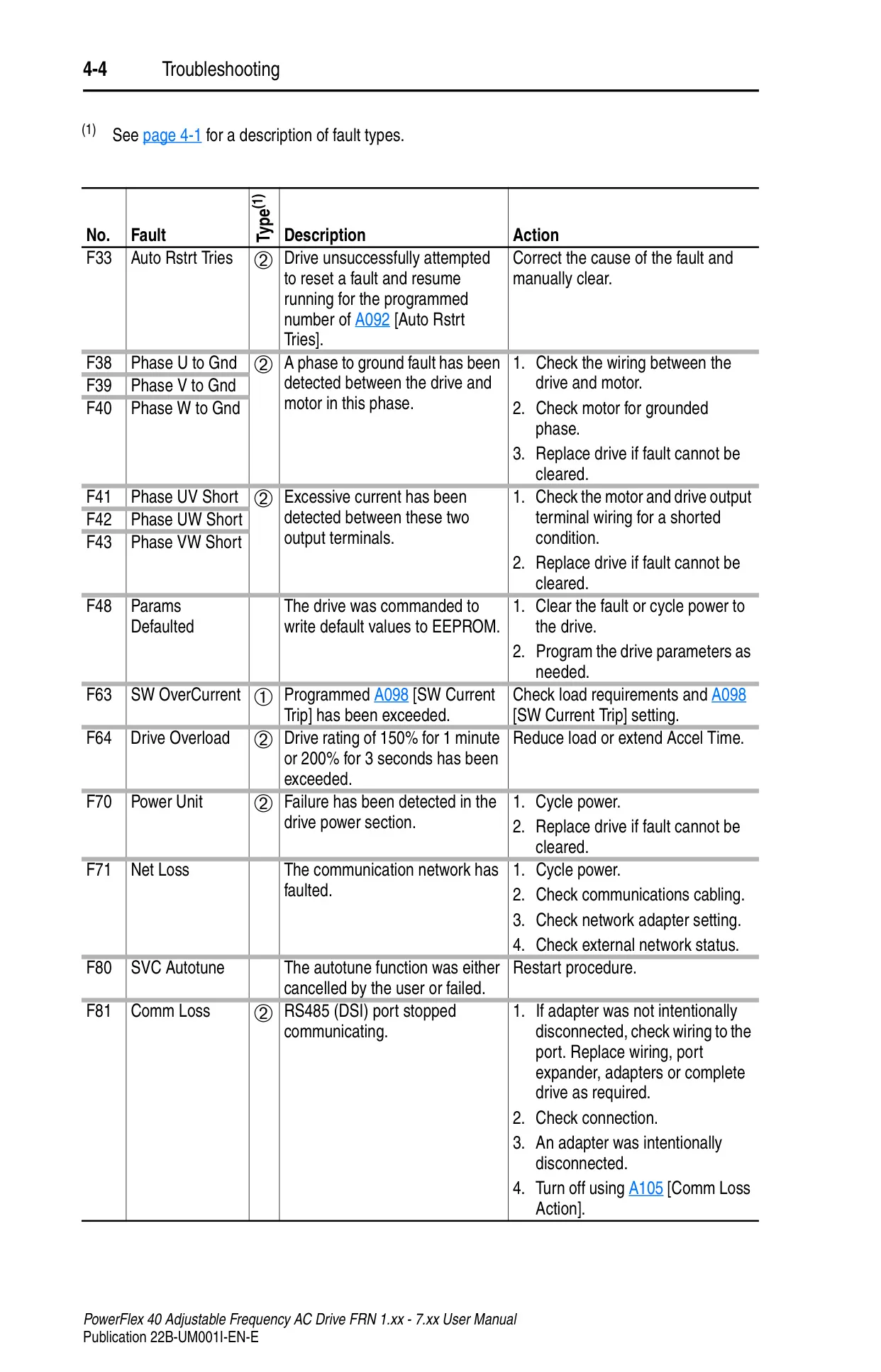
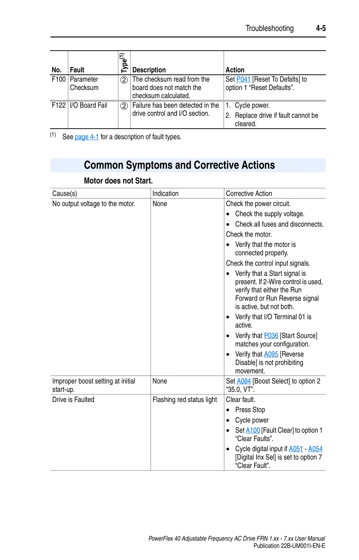
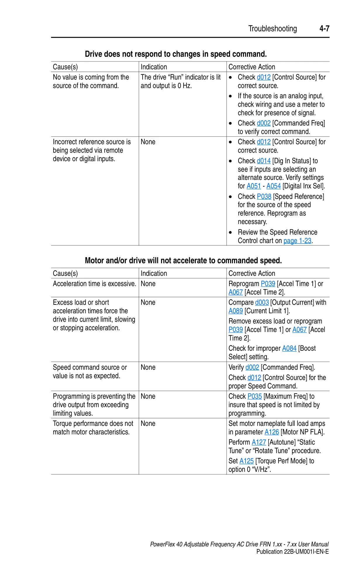
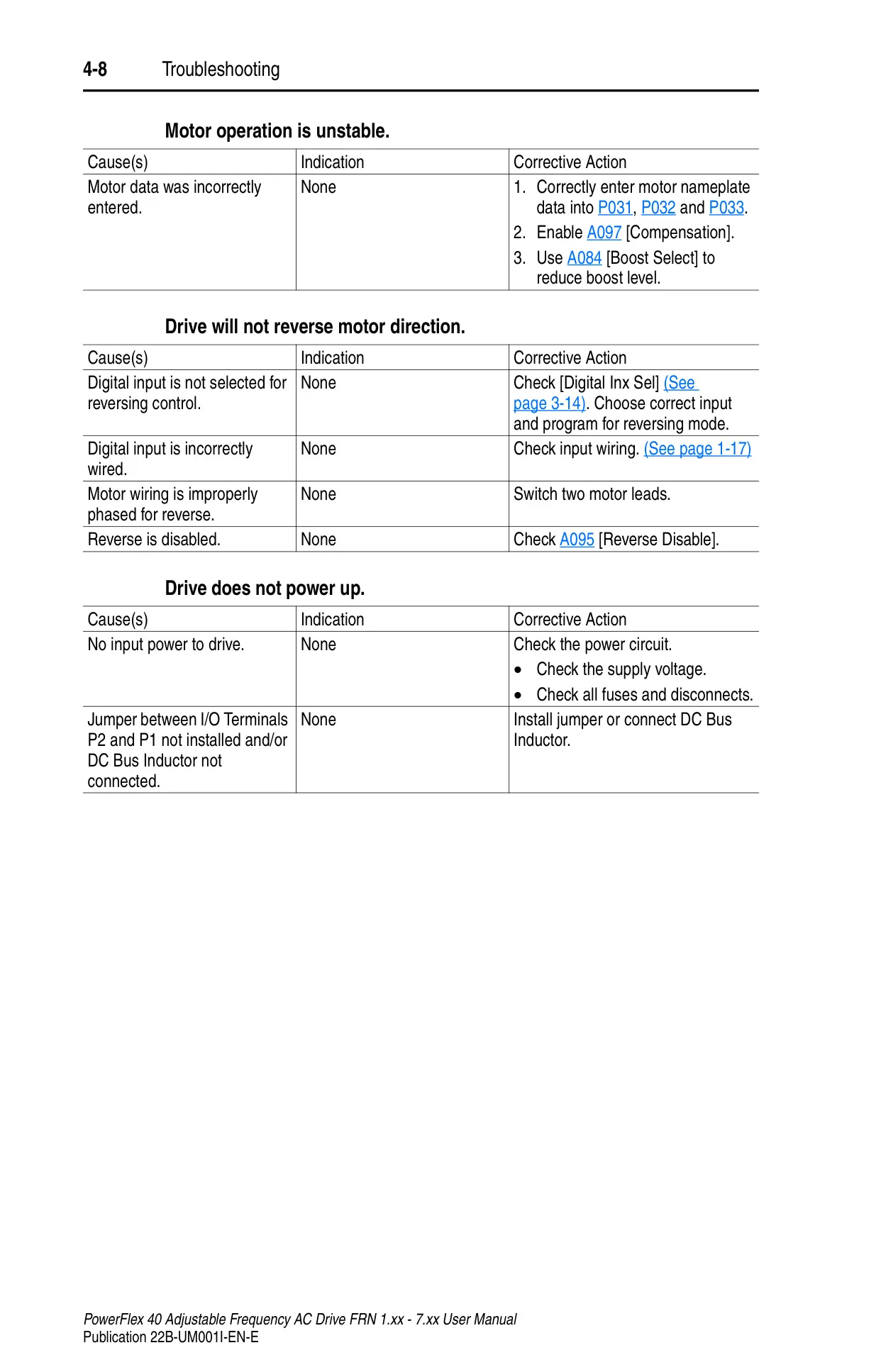
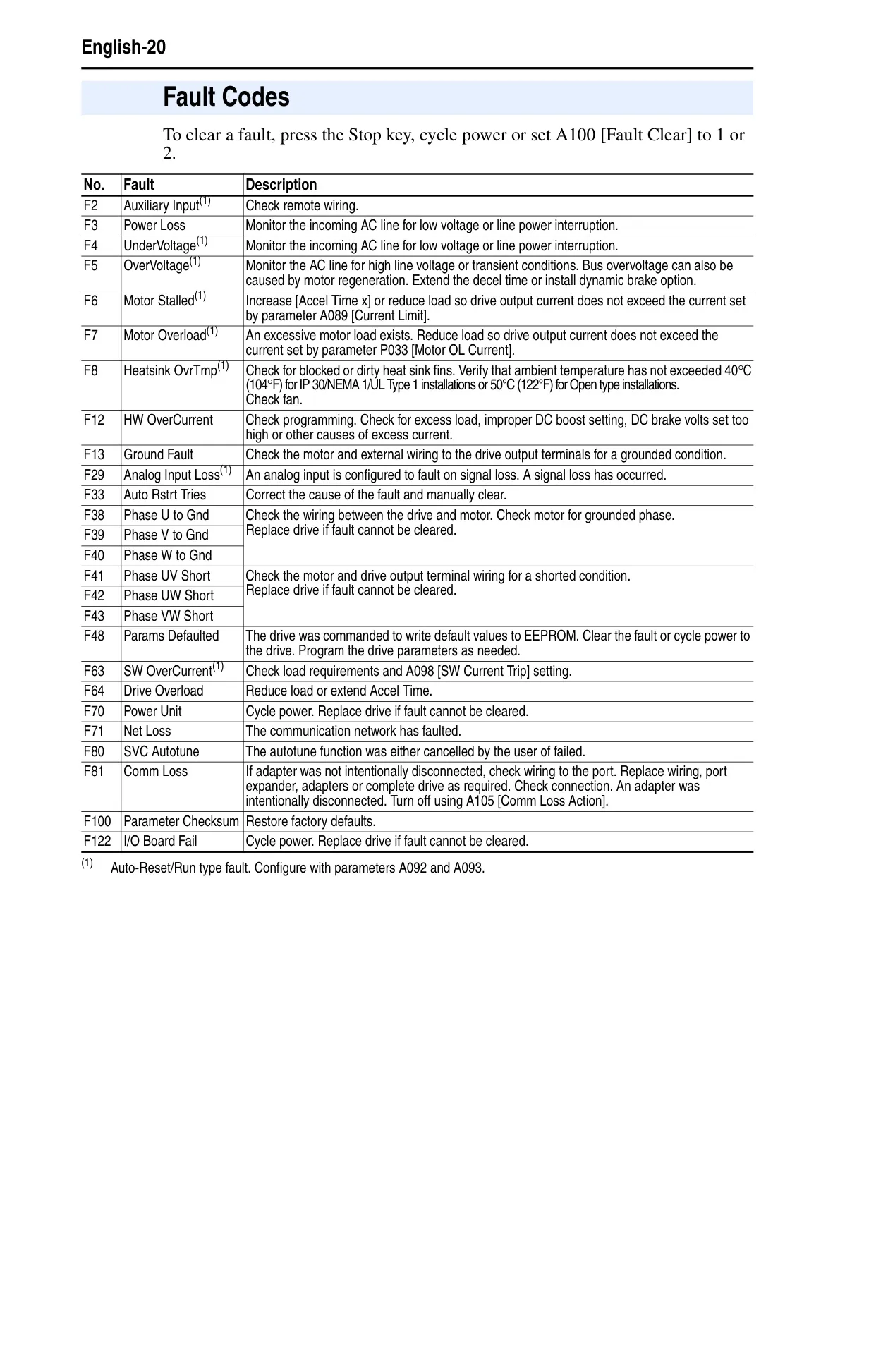
The PowerFlex 40 is equipped with comprehensive protective features, including I²t motor overload protection, overcurrent, overvoltage, and undervoltage trip limits. In the event of an issue, the drive indicates faults via LED displays and alphanumeric codes, categorized into auto-resettable and non-resettable types. The manual provides detailed fault descriptions and corrective actions, along with common symptoms like "motor does not start" or "motor operation is unstable," guiding users through effective troubleshooting procedures.
Frequently Asked Questions (FAQs)
Can't find the answer you need? Here are some frequently asked questions about the Allen-Bradley Powerflex 40, and we answer them below.