
Chamberlain 045ACT Receiver Logic Board Instruction Manual
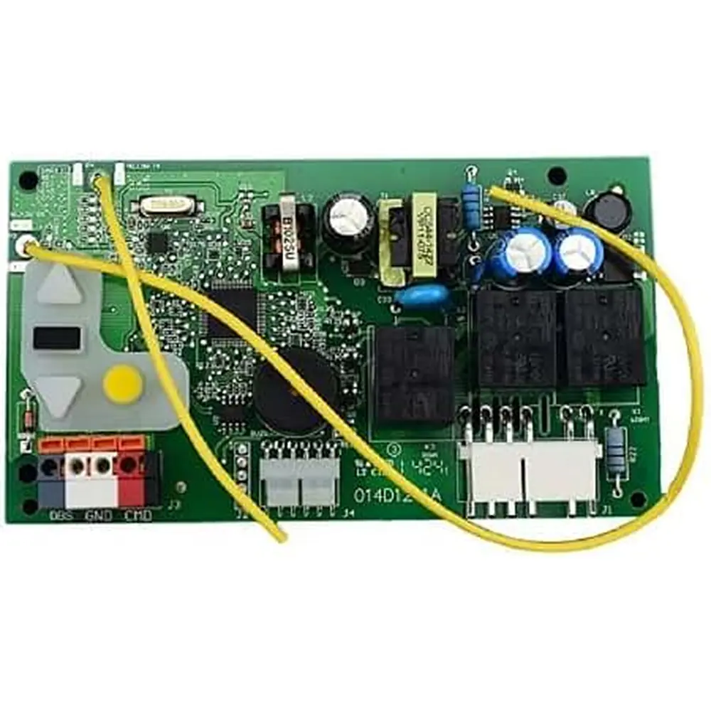
Chamberlain 045ACT Receiver Logic Board
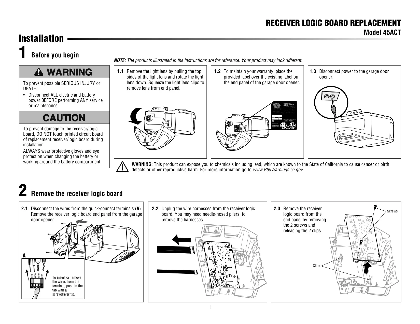
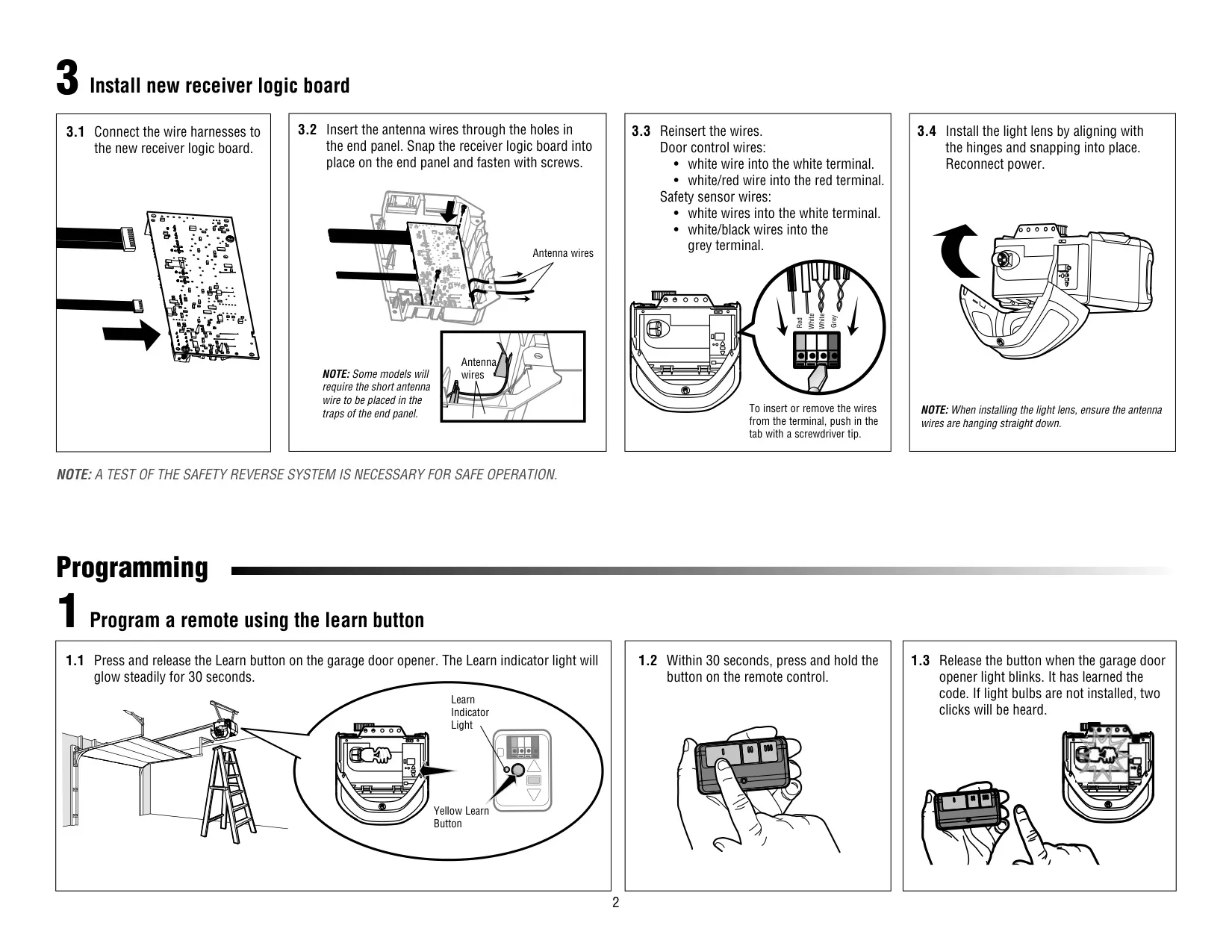
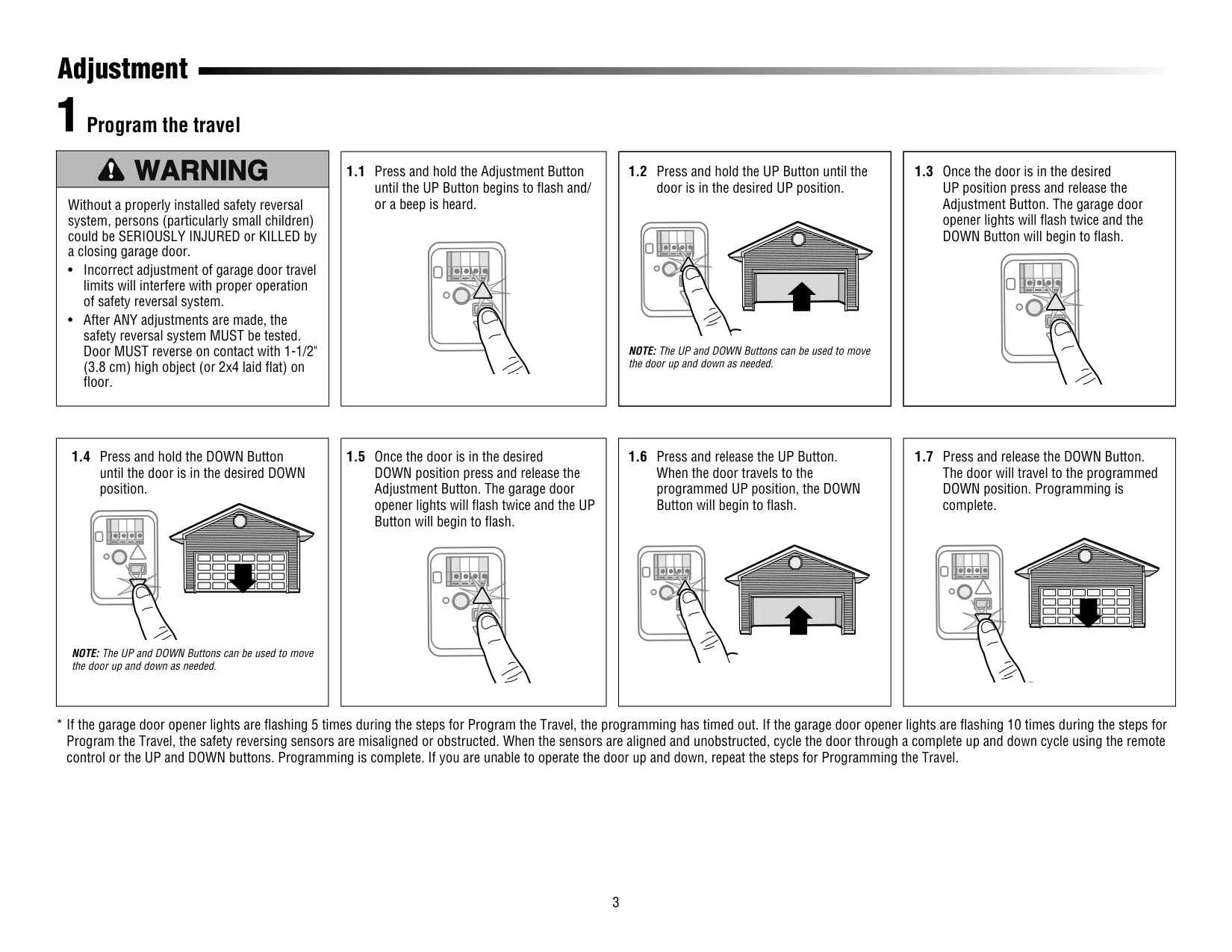


Chamberlain 045ACT Instructions
Here we offer the Chamberlain 045ACT Receiver Logic Board manual completely free and in English. We have cataloged this manual in the Receiver Logic Boards section on Manualverse, and it has been rated by 1 users with an average rating of 5. If you have any specific questions about Chamberlain 045ACT Receiver Logic Board, we suggest checking the Frequently Asked Questions (FAQs) section of this manual.
Product Images
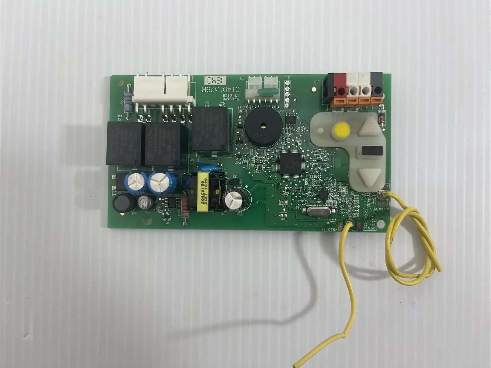
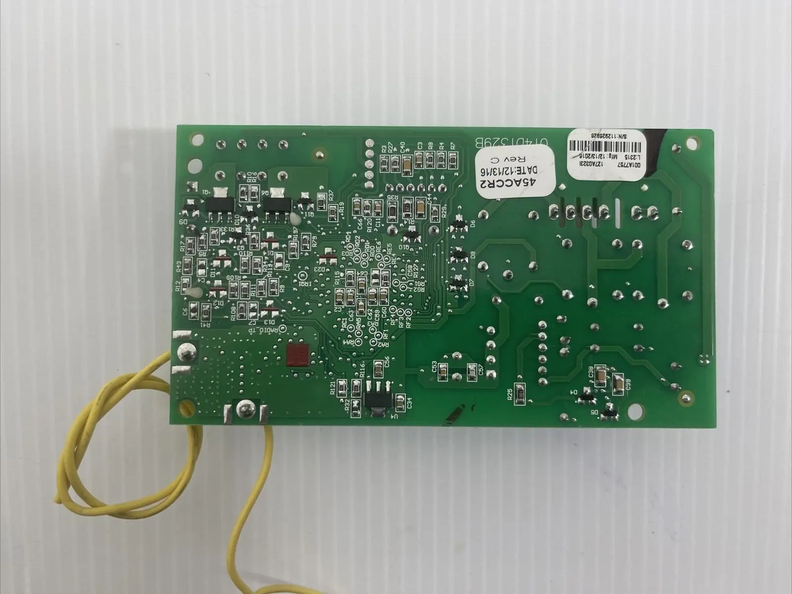
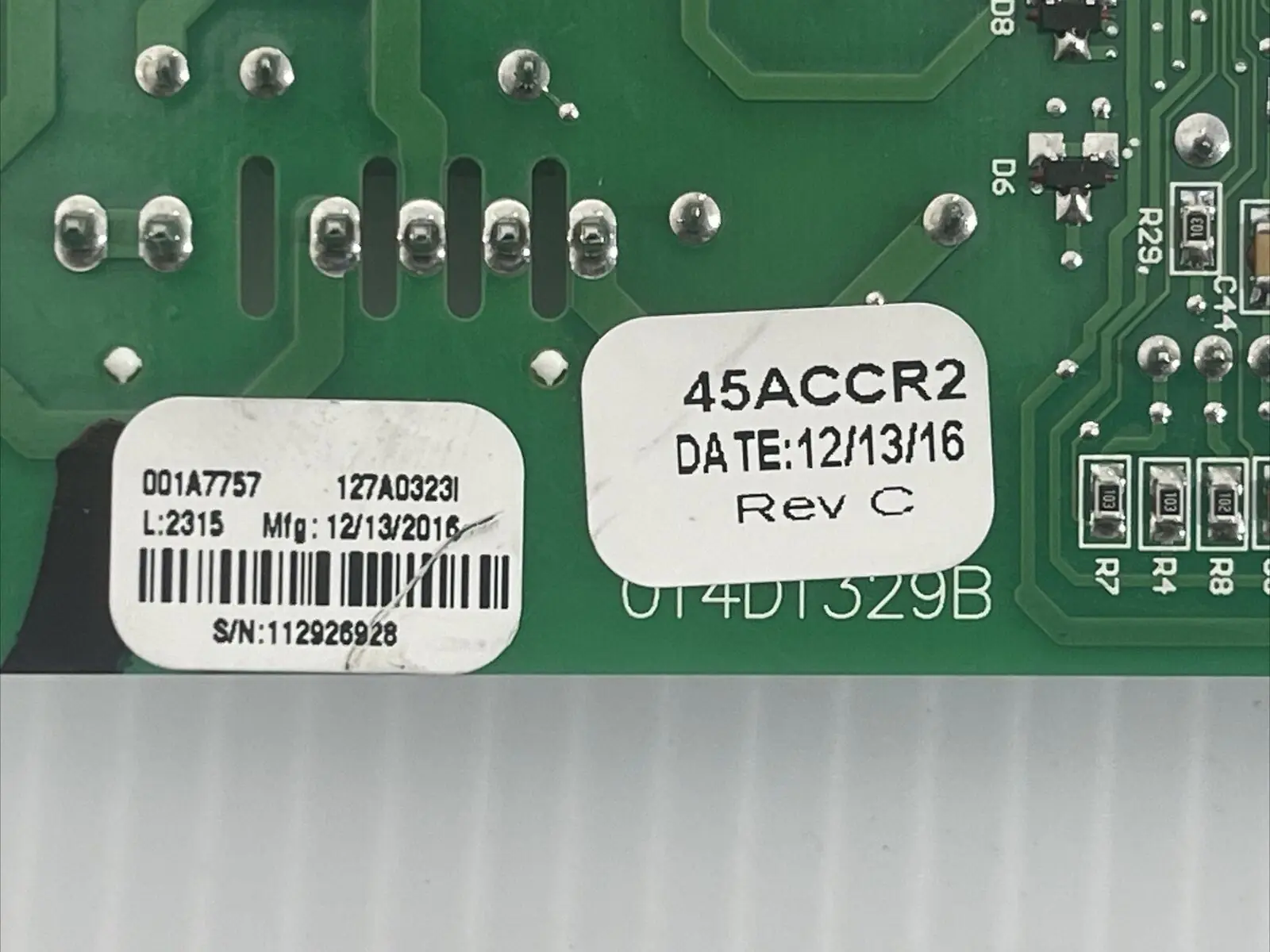
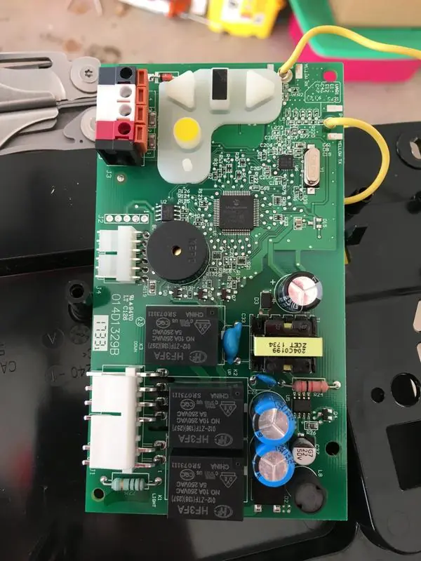
Chamberlain 045ACT Receiver Logic Board Specifications
| Feature | Specification |
|---|---|
| Manufacturer | The Chamberlain Group, Inc., USA |
| Model | 45ACT (045ACT) |
| Product Type | Replacement receiver logic board for garage door openers |
| Mounting Location | End panel of the garage door opener, behind the light lens |
| Mounting Hardware | 2 screws and 2 retaining clips |
| Wiring Terminals | Quick-connect push-in terminals: Red, White, White, Grey |
| Door Control Wiring | White wire to white terminal; white/red wire to red terminal |
| Safety Sensor Wiring | White wires to white terminal; white/black wires to grey terminal |
| Wire Release Method | Push in the terminal tab with a screwdriver tip |
| Learn Button | Yellow, with Learn indicator light |
| Learn Mode Duration | 30 seconds (indicator glows steadily) |
| Remote Programming Confirmation | Opener light blinks, or two clicks if no bulbs are installed |
| Erase All Receiver Codes | Press and hold the orange ERASE button for 6 seconds, then release when the indicator turns off |
| Travel Limit Controls | Adjustment Button plus UP and DOWN Buttons |
| Programming Timeout Indication | Opener lights flash 5 times |
| Sensor Fault Indication | Opener lights flash 10 times (sensors misaligned or obstructed) |
| Safety Reversal Test Object | 1-1/2 in (3.8 cm) high board, or a 2x4 laid flat |
| Safety Reversal Test Frequency | Every month and after any adjustment |
| Protector System Maximum Travel When Obstructed | No more than 1 in (2.5 cm) |
| Safety Sensor Mounting Height | No more than 6 in (15 cm) above the floor |
| Label Part Number | 132C2280-3D |
| Assembly Origin | Assembled in Mexico |
Chamberlain 045ACT Receiver Board Details
The Chamberlain 45ACT Receiver Logic Board is a service replacement part that restores the radio receiver and control logic of a compatible Chamberlain garage door opener. The kit includes a new label, which goes over the existing label on the opener's end panel. Applying this label is required to keep the warranty valid, so it should be part of every installation. The manual notes that the illustrations are for reference only and that your opener may look different from the drawings.
Safety comes first. Before any service, all electric and battery power must be disconnected to avoid serious injury or death. Wear protective gloves and eye protection when working near the battery compartment. The manual also warns not to touch the printed circuit board of the new receiver logic board during installation, because handling it can damage the electronics. A California Proposition 65 notice states that the product can expose users to chemicals including lead.
To reach the board, you remove the light lens by pulling on its top sides, rotating it down, and squeezing its clips to free it from the end panel. After the wires are released from the quick-connect terminals, the end panel comes off the opener. The internal wire harnesses can be tight, so the manual suggests needle-nosed pliers to unplug them. The old board then comes out once the screws are removed and the clips are released.
When installing the new board, you connect the harnesses first. Then you feed the antenna wires through the holes in the end panel and snap the board into place before securing it. On some models, the short antenna wire must sit in the traps molded into the end panel. When you put the light lens back by aligning it with its hinges, make sure the antenna wires hang straight down for best radio reception. Power is reconnected only after this step.
The travel programming routine guides you with lights and button cues. Holding the Adjustment Button makes the UP Button flash and/or produces a beep. You then set the up and down limits in turn. After each limit is confirmed, the opener lights flash twice. A final up-and-down run finishes the setup. If programming times out or the sensors detect a problem, you fix the cause, run a full cycle, and repeat the procedure if the door still won't move correctly.
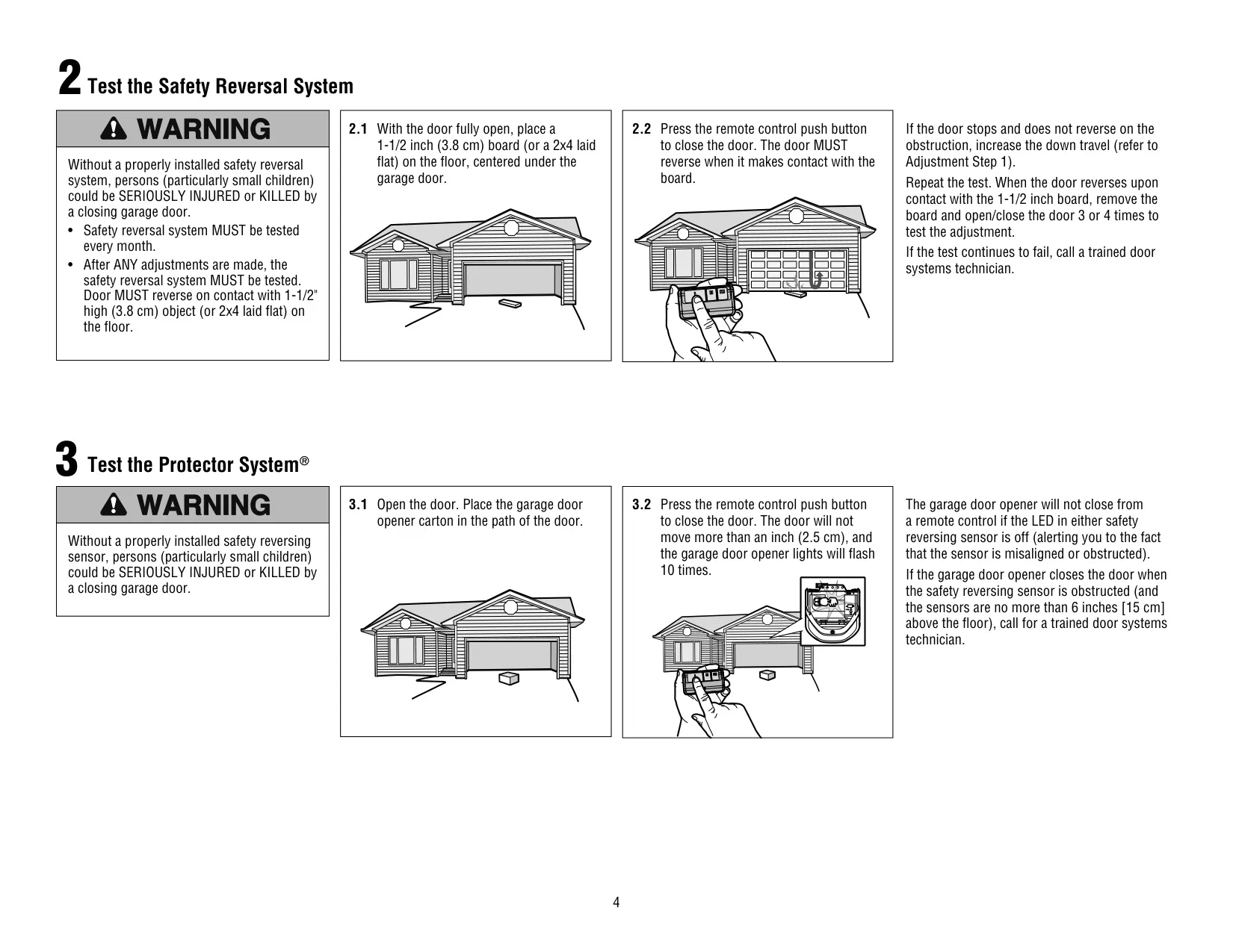
After installation, the manual requires a safety reversal test. If the door stops on the test board without reversing, increase the down travel and test again. Once the door reverses, remove the board and run the door 3 or 4 times to confirm the adjustment. The Protector System® test uses the opener carton as an obstruction. The opener will not close from a remote while either sensor LED is off. If any test keeps failing, call a trained door systems technician.
Frequently Asked Questions (FAQs)
Can't find the answer you need? Here are some frequently asked questions about the Chamberlain 045ACT Receiver Logic Board, and we answer them below.