
Generac 200 AMP Automatic Transfer Switch Instruction Manual
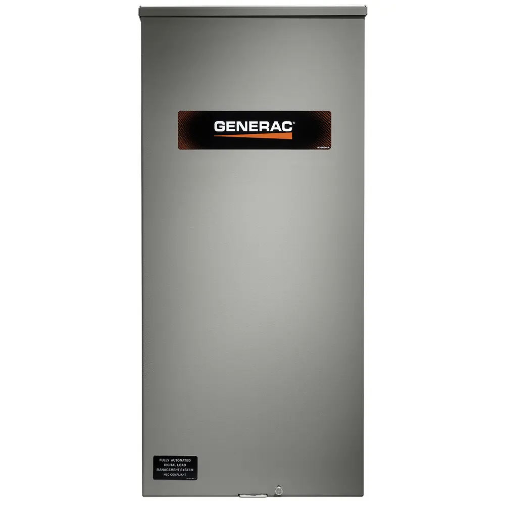
Generac 200 AMP Automatic Transfer Switch







Generac 200 AMP Instructions
Here we offer the Generac 200 AMP Automatic Transfer Switch manual completely free and in English. We have cataloged this manual in the Automatic Transfer Switches section on Manualverse, and it has been rated by 1 users with an average rating of 5. If you have any specific questions about Generac 200 AMP Automatic Transfer Switch, we suggest checking the Frequently Asked Questions (FAQs) section of this manual.
Product Images


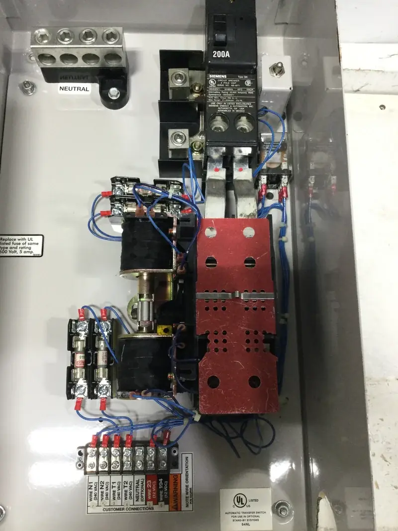
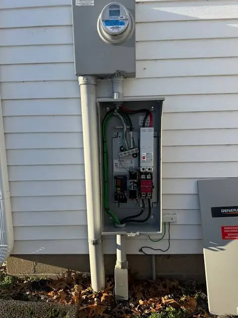
Generac 200 AMP Specifications
| Feature | Specification |
|---|---|
| Product Series | RTS "HS" Type Automatic Transfer Switch |
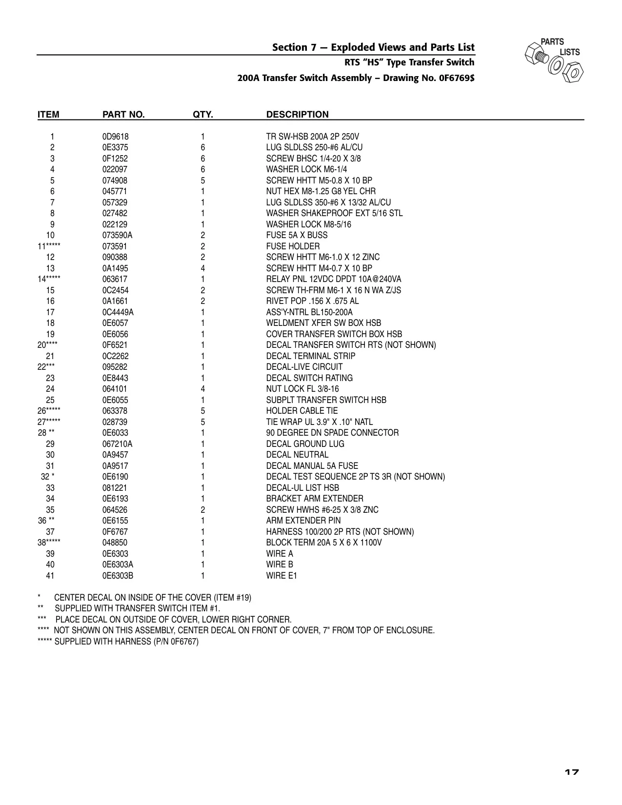
| Switch Mechanism Part Number | 0D9618 (TR SW-HSB 200A 2P 250V) |
| Assembly Drawing Number | 0F6769 |
| Ampere Rating | 200 A |
| Number of Poles | 2-pole (neutral not switched) |
| System Type | Single-phase |
| Mechanism Voltage Rating | 250 V |
| Short-Circuit Withstand Rating | 10,000 RMS symmetrical amperes at 240 VAC |
| Required Upstream Protection | Circuit breaker without adjustable short time response, or fuses |
| Tungsten Load Limit | Not to exceed 30% of switch rating |
| Suitable Load Types | Motors, electric discharge lamps, tungsten filament and electric heating equipment |
| Application | Optional standby systems only |
| Enclosure Type | NEMA 3R (outdoor, rain and sleet protection) |
| Enclosure Dimensions (Drawing 0E7081) | 508.5 mm (20.02") x 294 mm (11.57") x 179.5 mm (7.07") |
| Mounting Hole Diameter | 6.3 mm (0.25") |
| Conduit Knockouts | 3 places, suitable for 1", 1-1/2" and 2" conduit |
| Mounting | Wall-mounted, vertical |
| Power Terminal Wire Range | #6 AWG to 250 MCM |
| Power Lug Tightening Torque | 275 in-lbs |
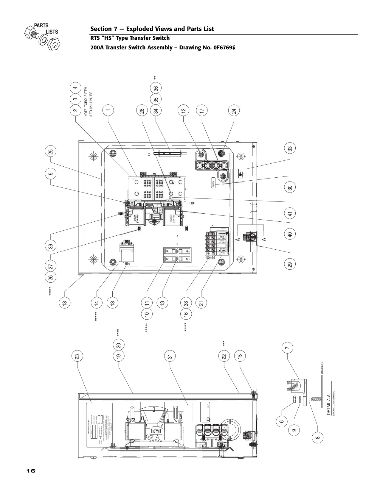
| Power Terminal Lugs | 6 x solderless lugs 250-#6 AL/CU (P/N 0E3375) |
| Ground Lug | Solderless lug 350-#6 AL/CU (P/N 057329) |
| Conductor Type | Copper or aluminum, minimum 75°C rating |
| Neutral Block | 150-200 A neutral block assembly (P/N 0C4449A) |
| Transfer Relay | 12 VDC DPDT, 10 A at 240 VA (P/N 063617) |
| Control Fuses (F1, F2) | 2 x 5 A (P/N 073590A) |
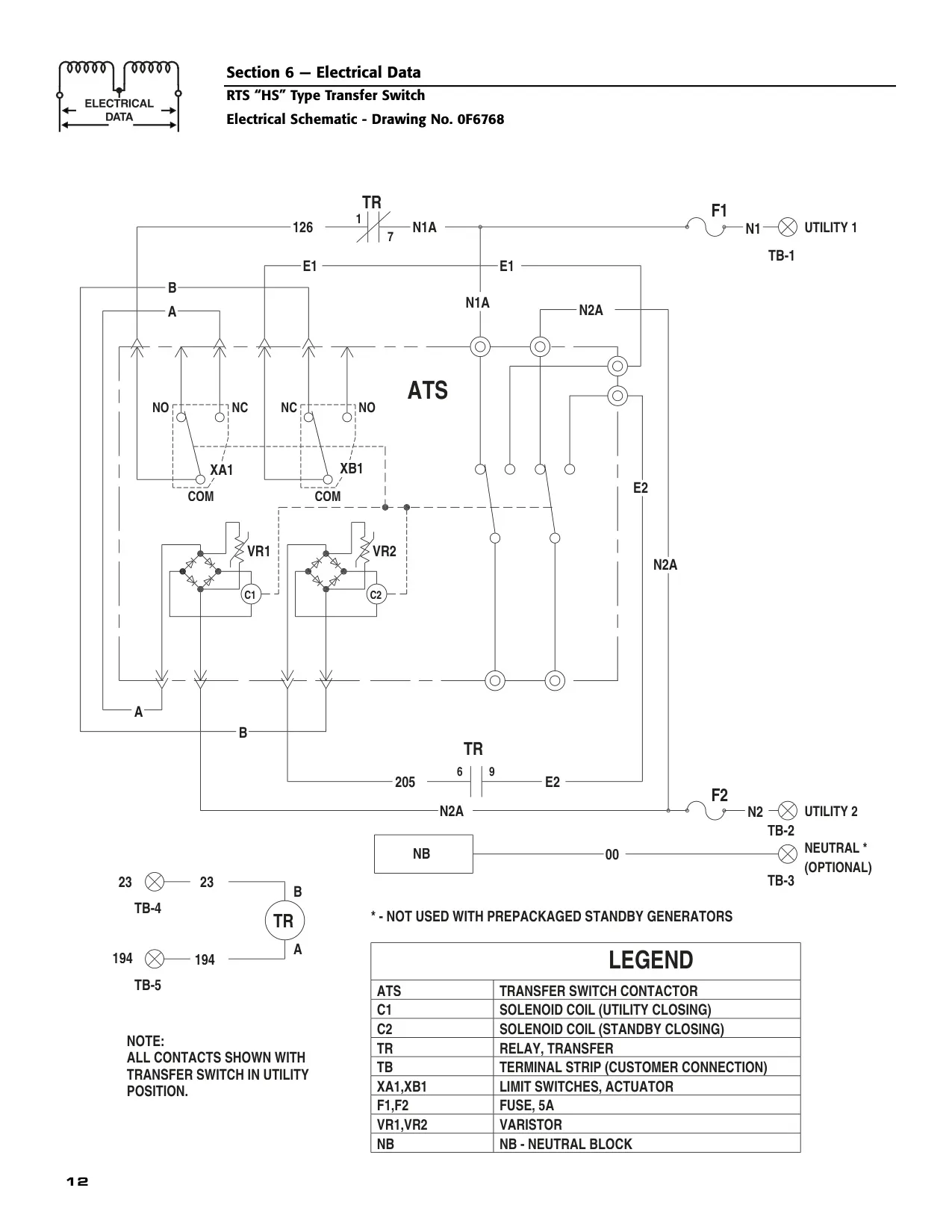
| Surge Suppression | Varistors VR1 and VR2 |
| Closing Coils | C1 (utility closing) and C2 (standby closing) solenoid coils |
| Customer Terminal Block | 5-position, 20 A, 1100 V (P/N 048850) |
| Customer Control Connections | Utility 1 (N1), Utility 2 (N2), Neutral (optional), 23, 194 |
| Control Wire up to 460 ft (140 m) | No. 18 AWG |
| Control Wire 461 to 730 ft (223 m) | No. 16 AWG |
| Control Wire 731 to 1,160 ft (354 m) | No. 14 AWG |
| Control Wire 1,161 to 1,850 ft (565 m) | No. 12 AWG |
| Minimum Electrical Clearance | 1/2 inch between live metal and grounded metal (100-400 A circuits) |
| Applicable Standards | UL 1008, NFPA 70 (NEC), CSA C22.1 |
| Manual Part Number | 0F6770, Revision 0 (05/19/05) |
Generac 200 AMP Details
The Generac 200 AMP Automatic Transfer Switch moves electrical loads from the UTILITY (NORMAL) source to the EMERGENCY (STANDBY) generator. This happens automatically when utility power fails or drops a lot, and only after generator voltage and frequency reach acceptable levels. The switch also keeps electricity from feeding back between the two sources. That protects the generator and keeps utility line workers safe, which is why electrical codes require transfer equipment in every standby installation.
The unit has three main parts: a transfer mechanism, a relay control and a terminal strip for the sensing wires. It is wired and tested at the factory. Installation covers mounting the enclosure, connecting the power source and load leads, wiring the generator start and sensing circuit, adding any auxiliary contacts and running the functional tests. When you unpack the switch, check it closely for shipping damage. Any claims must be filed with the carrier. Remove all packing material before installing.
Handle the switch with care. Don't drop it, and keep construction grit and metal chips out of it. Mount it as close as possible to the loads it will serve, upright on a rigid structure. Level all mounting points so the switch doesn't distort, using washers behind the mounting holes if needed. Never install a switch that has been damaged. The manual recommends posting a copy of the safety rules near the switch.
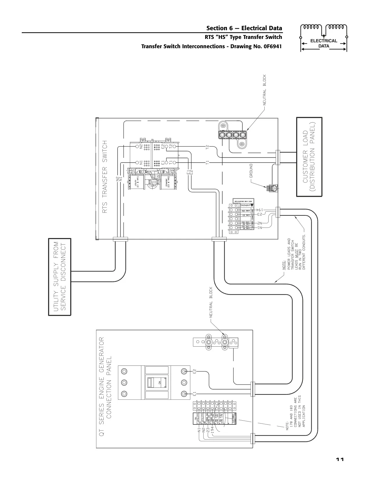
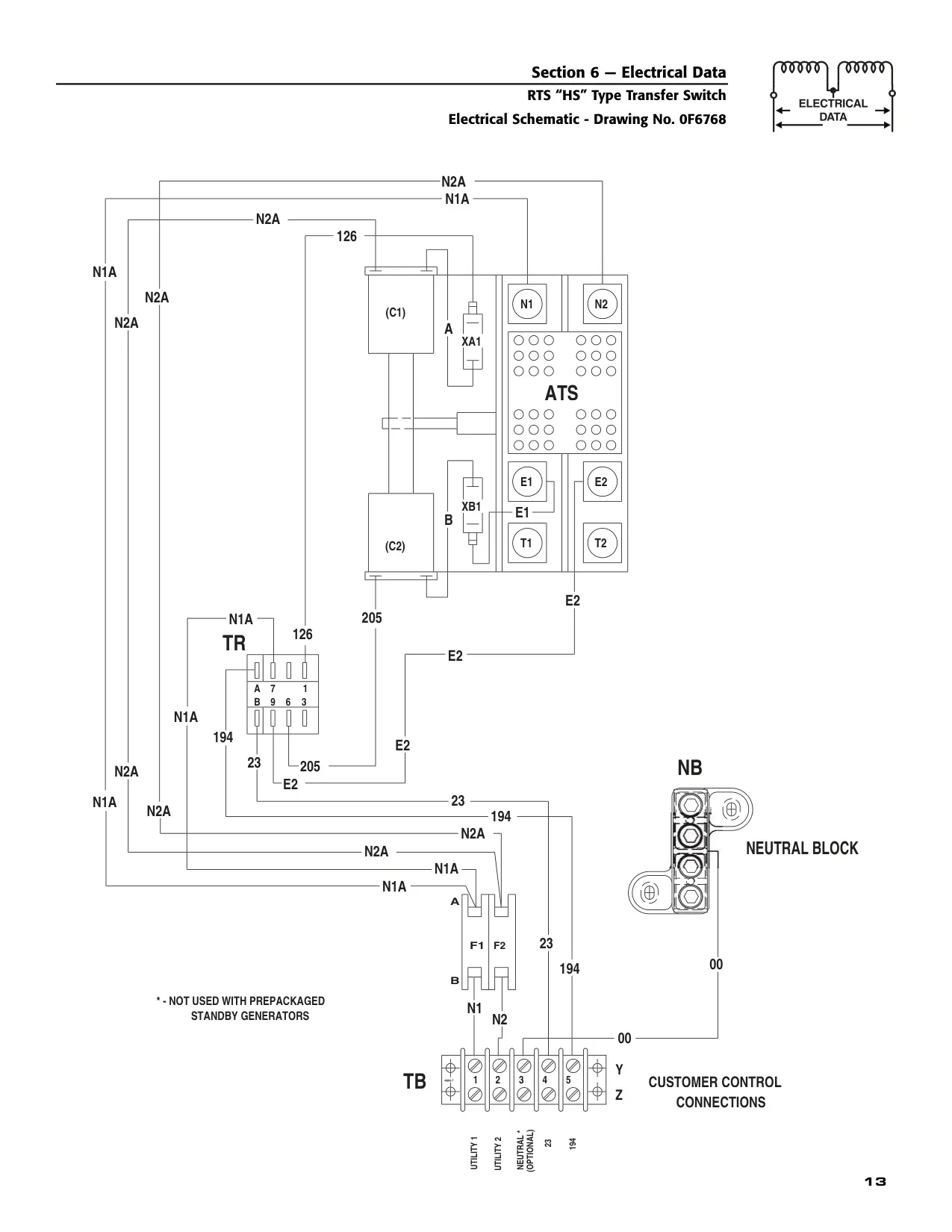
Connect the utility cables to terminals N1 and N2, the generator cables to E1 and E2 and the load leads to T1 and T2. Clean surface oxides off the cable ends with a wire brush before you connect them. If you use aluminum conductors, apply corrosion inhibitor and wipe off the excess after tightening. Use a torque wrench to tighten the lugs. Overtightening can damage the switch base, and a loose connection causes heat that can damage it too.
The switch ships with a manual operating handle. Check manual operation before you operate the switch electrically, and never transfer by hand while the switch is under load. Handle UP connects the load to the utility source. Handle DOWN connects it to the generator. Hold the handle firmly, because it snaps quickly once it passes the center of travel. Don't use too much force. When you're done, put the handle back in its storage spot inside the enclosure.
Voltage checks start with the utility supply, measured across N1 and N2 and from each line to neutral. Next, run the generator with no load for at least five minutes. Its readings should be 60-62 Hz, 240-246 VAC across E1 and E2, and 120-123 VAC from each leg to neutral. If voltage is right but frequency is wrong, the governed engine speed probably needs adjusting. If frequency is right but voltage is wrong, the voltage regulator may need adjusting.
For the load test, transfer the switch to standby by hand, start the generator and apply loads up to its full rated capacity. At maximum load, you should read more than 230 volts and more than 59 Hz across E1 and E2. Let it run for at least 30 minutes and listen for unusual noise, vibration or overheating. Then cool the generator down with no load, move the switch back to utility, turn utility power back on and set the generator to AUTO.
The warranty for this transfer switch follows the terms in the owner's manual of the Generac generator it is used with. Warranty claims must be inspected by an authorized Generac service dealer. You can find one at www.generac.com or by calling 1-800-333-1322. Generac's liability is limited to repairing or replacing defective parts.
Frequently Asked Questions (FAQs)
Can't find the answer you need? Here are some frequently asked questions about the Generac 200 AMP Automatic Transfer Switch, and we answer them below.